US5035446A - Adjustable steering wheel - Google Patents
Adjustable steering wheel Download PDFInfo
- Publication number
- US5035446A US5035446A US07/435,470 US43547089A US5035446A US 5035446 A US5035446 A US 5035446A US 43547089 A US43547089 A US 43547089A US 5035446 A US5035446 A US 5035446A
- Authority
- US
- United States
- Prior art keywords
- steering wheel
- steering
- steering column
- setting motor
- shaft
- Prior art date
- Legal status (The legal status is an assumption and is not a legal conclusion. Google has not performed a legal analysis and makes no representation as to the accuracy of the status listed.)
- Expired - Fee Related
Links
Images
Classifications
-
- B—PERFORMING OPERATIONS; TRANSPORTING
- B62—LAND VEHICLES FOR TRAVELLING OTHERWISE THAN ON RAILS
- B62D—MOTOR VEHICLES; TRAILERS
- B62D1/00—Steering controls, i.e. means for initiating a change of direction of the vehicle
- B62D1/02—Steering controls, i.e. means for initiating a change of direction of the vehicle vehicle-mounted
- B62D1/16—Steering columns
- B62D1/18—Steering columns yieldable or adjustable, e.g. tiltable
- B62D1/181—Steering columns yieldable or adjustable, e.g. tiltable with power actuated adjustment, e.g. with position memory
Definitions
- the present invention relates to a steering wheel arrangement intended for automotive vehicles and including a steering wheel, a steering column which carries the steering wheel, and means for adjusting the position of the steering wheel in the direction of the steering column and/or with respect to the angle at which the steering wheel is inclined to said column.
- Hitherto known steering wheel arrangements with adjustable steering wheels include manually operable catch devices and are so configured that the actual adjustment to the steering wheel position is effected totally through the force applied to the steering wheel by the driver of the vehicle.
- the adjustment is thus effected through a completely manual procedure, in which the driver first releases the catch, e.g. with the aid of a knob or an operating lever of the same kind as the lever used for operating the direction blinkers or indicators of the vehicle. While holding the catch released, the driver then moves or tilts the steering wheel to the position desired, whereafter he releases the catch operating lever, so as to lock the steering wheel in its new position.
- the object of the present invention is to provide a steering wheel arrangement of the kind disclosed in the introduction which is easier to adjust than the known arrangements and which will enable the steering wheel to be adjusted quickly to precisely the position desired by the driver in a traffic safe fashion.
- the steering wheel adjustment means include at least one setting motor for effecting adjustment movements and means for detecting the force acting on the steering wheel in the adjustment direction, said means being effective in starting the setting motor upon detection of a predetermined force in the adjustment direction and holding the motor active until the force acting in said adjustment direction falls beneath said predetermined force.
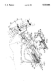
- FIG. 1 is a partially sectioned side view of one embodiment of the inventive steering wheel arrangement; and FIG. 2 is a longitudinal sectional view of a setting motor.
- the reference numeral 1 identifies the instrument panel of an automobile indicated in broken lines.
- the tube, or jacket, 3 has a main part 4 which is mounted for axial displacement in the bracket structure 2.
- the bracket structure 2 includes a bottom sleeve 5 which has an insert 6 made of suitable low-friction material.
- Located at the upper end of the bracket structure is a pair of flanges 7 which project downwardly on respective sides of the part 4 of the steering column tube and which have provided therein grooves 8 into which axially extending ribs 9 on the tube part 4 project.
- the steering column tube 3 also comprises an upper, shorter part 10 which is pivotally mounted at 11 to the tube part 4, so as to be able to swing in the longitudinal vertical plane of the vehicle.
- a part 12 of a steering shaft is mounted for rotation in the tube part 10 while being held against axial movement in said tube part.
- the outer end of said part carries a steering wheel 13.
- the aforesaid part 12 of the steering shaft extends into the tube part 4 via a suitable, known universal coupling whose pivot axis coincides with the rotational axis of the tube part 10.
- This latter arrangement is intended to allow adjustments to be made intentionally to the position of the steering wheel and also to ensure that the whole of the steering arrangement can "collapse" in the event of a collision.
- the aforedescribed embodiment enables positional adjustments to be made to the steering wheel 13, both in the direction of the longitudinal axis of the tube part 4 and also with regard to the angle of the steering wheel to said axis.
- the actual adjustments are carried out with the aid of two setting motors 20, 21, which in the case of the illustrated embodiment comprise two electric servomotors.
- the servomotor 20 is operative in effecting the axial adjustment and is housed in a housing 22 pivotally mounted in the lower sleeve 5 of the bracket structure 2.
- the operating rod 23 of the motor 20 is connected to a shaft pin 24 rigidly mounted between a pair of lugs 25 on the tube part 4 of the steering column. Consequently, when the rod 23 is displaced axially in relation to the housing 22, the steering column tube 3 will be moved axially in relation to the bracket structure 2 and therewith change the axial distance between the steering wheel 13 and the instrument panel 1.
- the maximum distance between the respective terminal positions of the steering wheel, indicated in chain lines, is referenced "A" in FIG. 1.
- the servomotor 21 is operative in effecting angular adjustments to the steering wheel position, and is housed in a housing 26 which is pivotally mounted on the shaft pin 24.
- the operating rod 27 of the motor 21 is joined to a shaft pin 28 which is rigidly mounted between a pair of lugs 29 on the tubular part 10 of the steering column.
- the tubular part 10 can be angled between the angular positions indicated in chain lines in FIG. 1, by displacement of the rod 27 relative to the housing 26.
- FIG. 2 illustrates the construction of the servomotor 20, 21 in more detail, and also illustrates schematically the means used for starting and stopping the motors.
- Respective motor housings 22, 26 include an electric motor 30.
- the output shaft of the respective motors carries a gear wheel 31 which meshes with a gear ring 32 on a nut which engages a screwthreaded part of respective operating rods 23, 27.
- the outer ends of the respective operating rods are provided with a sleeve 33 which has on its outer periphery a shoulder 34 which projects between a pair of metal contacts on a make-and-break switch 35 incorporated in the electric circuit in which the motor is connected.
- the sleeve 33 on respective operating rods, or arms, 23, 27 engages around its respective shaft pin 24, 28 through the intermediary of a resilient element 36, which may be a bush made of an elastic material.
- Each of the switches 35 is intended to accompany the part whose position is changed by its respective servomotor, i.e. the steering column parts 4 and 10, wherein the modus operandi of the arrangement is as follows:
- servomotors other than electrical, self-locking nut and screw type servomotors may be used.
- the servomotors used are not self-locking, it will be necessary to provide separate locking devices which co-act with the servomotors in a manner such that the locking devices will be deactivated and activated respectively when the motors are started and stopped.
Landscapes
- Engineering & Computer Science (AREA)
- Chemical & Material Sciences (AREA)
- Combustion & Propulsion (AREA)
- Transportation (AREA)
- Mechanical Engineering (AREA)
- Steering Controls (AREA)
- Electric Propulsion And Braking For Vehicles (AREA)
Applications Claiming Priority (2)
| Application Number | Priority Date | Filing Date | Title |
|---|---|---|---|
| SE870248 | 1987-06-15 | ||
| SE8702484A SE457871B (sv) | 1987-06-15 | 1987-06-15 | Rattanordning foer motorfordon |
Publications (1)
| Publication Number | Publication Date |
|---|---|
| US5035446A true US5035446A (en) | 1991-07-30 |
Family
ID=20368862
Family Applications (1)
| Application Number | Title | Priority Date | Filing Date |
|---|---|---|---|
| US07/435,470 Expired - Fee Related US5035446A (en) | 1987-06-15 | 1988-06-13 | Adjustable steering wheel |
Country Status (5)
| Country | Link |
|---|---|
| US (1) | US5035446A (sv) |
| JP (1) | JP2647476B2 (sv) |
| DE (1) | DE3890516C2 (sv) |
| SE (1) | SE457871B (sv) |
| WO (1) | WO1988010205A1 (sv) |
Cited By (33)
| Publication number | Priority date | Publication date | Assignee | Title |
|---|---|---|---|---|
| US5275066A (en) * | 1991-11-07 | 1994-01-04 | The Torrington Company | Motored adjustable steering column |
| US5439252A (en) * | 1993-04-22 | 1995-08-08 | Trw Inc. | Dual pivot steering column |
| US5520416A (en) * | 1994-10-03 | 1996-05-28 | Ford Motor Company | Power tilt, telescoping and internally collapsible steering column |
| US5590565A (en) * | 1995-02-08 | 1997-01-07 | General Motors Corporation | Motor vehicle steering column |
| US5613404A (en) * | 1994-03-07 | 1997-03-25 | Case Corporation | Tiltable steering mechanism for an off-highway implement |
| US5722300A (en) * | 1996-08-16 | 1998-03-03 | General Motors Corporation | Motor vehicle steering column |
| EP0841236A2 (en) | 1996-11-12 | 1998-05-13 | New Holland Belgium N.V. | Four-way adjustable pedestal floor mounted steering column for a combine harvester |
| US5813699A (en) * | 1994-10-10 | 1998-09-29 | Leopold Kostal Gmbh & Co. Kg | Steering device for motor vehicles |
| US5871233A (en) * | 1995-11-24 | 1999-02-16 | Kabushiki Kaisha Tokai-Rika-Denki-Seisakusho | Steering device equipped with air bag |
| US5890397A (en) * | 1997-02-24 | 1999-04-06 | New Holland North America, Inc. | Four-way adjustable pedestal floor mounted steering column for a combine harvester |
| US6077597A (en) * | 1997-11-14 | 2000-06-20 | Outlast Technologies, Inc. | Interactive thermal insulating system having a layer treated with a coating of energy absorbing phase change material adjacent a layer of fibers containing energy absorbing phase change material |
| US6138525A (en) * | 1999-05-06 | 2000-10-31 | Delphi Technologies, Inc. | Motor vehicle steering column and method |
| US6390505B1 (en) * | 2000-04-19 | 2002-05-21 | International Truck Intellectual Property Company, L.L.C. | Steering column adjustment system using force feedback system |
| US20030094802A1 (en) * | 2001-11-19 | 2003-05-22 | Martin Budaker | Adjustable steering column |
| US20030122358A1 (en) * | 2001-12-28 | 2003-07-03 | Bannon Sean A. | Steering column with rotary tilt mechanism and method of installation |
| US20040000779A1 (en) * | 2002-06-27 | 2004-01-01 | Armstrong Ray G. | Electrically actuated steering column mechanism |
| US20040012184A1 (en) * | 2000-06-02 | 2004-01-22 | Hege Reitan | Device for allowing adjustment of the position of a steering member in a vehicle |
| US6711965B2 (en) | 1998-12-25 | 2004-03-30 | Nsk Ltd. | Electric steering column apparatus |
| US20040083844A1 (en) * | 2001-11-09 | 2004-05-06 | Krizan Joseph A. | Composite steering column housing |
| US20040251673A1 (en) * | 2003-06-16 | 2004-12-16 | Hyundai Mobis, Co., Ltd. | Tilt steering apparatus for vehicle |
| US7331608B2 (en) | 2002-06-27 | 2008-02-19 | Delphi Technologies, Inc. | Electrically actuated steering column mechanism |
| US20100059977A1 (en) * | 2007-01-24 | 2010-03-11 | Teruhisa Motojima | Structure of steering support portion |
| US20110121552A1 (en) * | 2009-11-25 | 2011-05-26 | Zf Systemes De Direction Nacam Sas | Device for adjusting a steering column |
| US8985628B2 (en) | 2011-08-16 | 2015-03-24 | GM Global Technology Operations LLC | Adjusting device |
| DE102017000354A1 (de) | 2017-01-17 | 2018-07-19 | Thyssenkrupp Ag | Elektro-mechanische Fixiervorrichtung für eine Lenksäule eines Kraftfahrzeugs |
| US10228047B2 (en) * | 2016-06-17 | 2019-03-12 | Robert Bosch Llc | Actuator for providing relative motion between two points |
| US20190084609A1 (en) * | 2017-09-21 | 2019-03-21 | Ford Global Technologies, Llc | Steering assembly |
| US20190152509A1 (en) * | 2016-04-08 | 2019-05-23 | Mmx - Meccanoplast S.R.L. | Steering column |
| US10368950B2 (en) * | 2013-12-06 | 2019-08-06 | Richard Wolf Gmbh | Drive arrangement for an endoscopic shaft-type instrument |
| US20200039562A1 (en) * | 2018-07-31 | 2020-02-06 | Steering Solutions Ip Holding Corporation | System and method of automatically stowing and unstowing a steering column assembly |
| US20200298900A1 (en) * | 2019-03-20 | 2020-09-24 | Volvo Car Corporation | Vehicle having multiple driving positions |
| US11203373B2 (en) * | 2017-10-23 | 2021-12-21 | Thyssenkrupp Presta Ag | Steering column for a motor vehicle |
| US20220017137A1 (en) * | 2019-10-21 | 2022-01-20 | Fnss Savunma Sístemlerí A.S. | A new generation dual-handle steering console for tracked military vehicles |
Families Citing this family (8)
| Publication number | Priority date | Publication date | Assignee | Title |
|---|---|---|---|---|
| FR2658776B1 (fr) * | 1990-02-28 | 1993-06-18 | Ecia Equip Composants Ind Auto | Colonne de direction reglable. |
| JP2949765B2 (ja) * | 1990-04-12 | 1999-09-20 | 日産自動車株式会社 | 車載装備品の姿勢制御装置 |
| FR2696145B1 (fr) * | 1992-09-28 | 1994-12-30 | Ecia Equip Composants Ind Auto | Ensemble de colonne de direction réglable en position pour véhicule automobile. |
| DE4238732C1 (de) * | 1992-11-17 | 1994-02-17 | Lemfoerder Metallwaren Ag | Verstellbare Lenksäule für Kraftfahrzeuge |
| DE19933678C2 (de) * | 1999-07-17 | 2001-05-23 | Daimler Chrysler Ag | Verstellvorrichtung für ein Mantelrohr einer Lenkungsanlage eines Kraftfahrzeugs |
| DE102011001765B4 (de) * | 2011-04-04 | 2013-10-17 | Zf Lenksysteme Gmbh | Lenksäulenhersteller unabhängige Adaption für Schnittstelle Lenksäule/Aktuator |
| FR3105149B1 (fr) * | 2019-12-18 | 2022-06-24 | Robert Bosch Automotive Steering Vendome | Dispositif de positionnement d’un volant et procede de reglage associe |
| BE1030167B1 (de) * | 2022-07-22 | 2023-08-01 | Thyssenkrupp Ag | Verstellantrieb für eine motorisch verstellbare Lenksäule und Lenksäule für ein Kraftfahrzeug |
Citations (11)
| Publication number | Priority date | Publication date | Assignee | Title |
|---|---|---|---|---|
| JPS59220454A (ja) * | 1983-05-26 | 1984-12-11 | Fujitsu Ten Ltd | ステアリングチルトコントロ−ル装置 |
| JPS6012375A (ja) * | 1983-07-01 | 1985-01-22 | Mazda Motor Corp | 電子キ−を備えた自動車の電動チルトステアリング装置 |
| JPS60157963A (ja) * | 1984-01-30 | 1985-08-19 | Nippon Denso Co Ltd | ステアリングホイ−ル位置自動調整装置 |
| JPS60157962A (ja) * | 1983-08-23 | 1985-08-19 | Aisin Seiki Co Ltd | ステアリングチルティング装置 |
| US4598604A (en) * | 1983-05-25 | 1986-07-08 | Daimler-Benz Aktiengesellschaft | Steering device for motor vehicles, adjustable along its longitudinal axis |
| US4602520A (en) * | 1983-06-23 | 1986-07-29 | Aisin Seiki Kabushiki Kaisha | Telescopic steering column assembly |
| JPS61218476A (ja) * | 1984-09-10 | 1986-09-27 | Aisin Seiki Co Ltd | ステアリングホイ−ルの姿勢設定装置 |
| JPS6239363A (ja) * | 1985-08-13 | 1987-02-20 | Aisin Seiki Co Ltd | 車上装備の姿勢設定装置 |
| JPS6274766A (ja) * | 1985-09-28 | 1987-04-06 | Aisin Seiki Co Ltd | パワ−式ステアリング位置設定装置 |
| DE3634977A1 (de) * | 1985-10-14 | 1987-04-16 | Fuji Kiko Kk | Anordnung zur neigung eines lenkrades mittels einer hilfsantriebskraft |
| US4893518A (en) * | 1987-04-17 | 1990-01-16 | Nippon Seiko Kabushiki Kaisha | Electric steering apparatus |
Family Cites Families (1)
| Publication number | Priority date | Publication date | Assignee | Title |
|---|---|---|---|---|
| JPS60138850U (ja) * | 1984-02-27 | 1985-09-13 | 三菱自動車工業株式会社 | ドライビングポジシヨン調整装置 |
-
1987
- 1987-06-15 SE SE8702484A patent/SE457871B/sv not_active IP Right Cessation
-
1988
- 1988-06-13 US US07/435,470 patent/US5035446A/en not_active Expired - Fee Related
- 1988-06-13 DE DE3890516A patent/DE3890516C2/de not_active Expired - Fee Related
- 1988-06-13 JP JP63505262A patent/JP2647476B2/ja not_active Expired - Lifetime
- 1988-06-13 WO PCT/SE1988/000317 patent/WO1988010205A1/en active Application Filing
Patent Citations (11)
| Publication number | Priority date | Publication date | Assignee | Title |
|---|---|---|---|---|
| US4598604A (en) * | 1983-05-25 | 1986-07-08 | Daimler-Benz Aktiengesellschaft | Steering device for motor vehicles, adjustable along its longitudinal axis |
| JPS59220454A (ja) * | 1983-05-26 | 1984-12-11 | Fujitsu Ten Ltd | ステアリングチルトコントロ−ル装置 |
| US4602520A (en) * | 1983-06-23 | 1986-07-29 | Aisin Seiki Kabushiki Kaisha | Telescopic steering column assembly |
| JPS6012375A (ja) * | 1983-07-01 | 1985-01-22 | Mazda Motor Corp | 電子キ−を備えた自動車の電動チルトステアリング装置 |
| JPS60157962A (ja) * | 1983-08-23 | 1985-08-19 | Aisin Seiki Co Ltd | ステアリングチルティング装置 |
| JPS60157963A (ja) * | 1984-01-30 | 1985-08-19 | Nippon Denso Co Ltd | ステアリングホイ−ル位置自動調整装置 |
| JPS61218476A (ja) * | 1984-09-10 | 1986-09-27 | Aisin Seiki Co Ltd | ステアリングホイ−ルの姿勢設定装置 |
| JPS6239363A (ja) * | 1985-08-13 | 1987-02-20 | Aisin Seiki Co Ltd | 車上装備の姿勢設定装置 |
| JPS6274766A (ja) * | 1985-09-28 | 1987-04-06 | Aisin Seiki Co Ltd | パワ−式ステアリング位置設定装置 |
| DE3634977A1 (de) * | 1985-10-14 | 1987-04-16 | Fuji Kiko Kk | Anordnung zur neigung eines lenkrades mittels einer hilfsantriebskraft |
| US4893518A (en) * | 1987-04-17 | 1990-01-16 | Nippon Seiko Kabushiki Kaisha | Electric steering apparatus |
Cited By (49)
| Publication number | Priority date | Publication date | Assignee | Title |
|---|---|---|---|---|
| US5275066A (en) * | 1991-11-07 | 1994-01-04 | The Torrington Company | Motored adjustable steering column |
| US5439252A (en) * | 1993-04-22 | 1995-08-08 | Trw Inc. | Dual pivot steering column |
| US5613404A (en) * | 1994-03-07 | 1997-03-25 | Case Corporation | Tiltable steering mechanism for an off-highway implement |
| US5520416A (en) * | 1994-10-03 | 1996-05-28 | Ford Motor Company | Power tilt, telescoping and internally collapsible steering column |
| US5813699A (en) * | 1994-10-10 | 1998-09-29 | Leopold Kostal Gmbh & Co. Kg | Steering device for motor vehicles |
| US5590565A (en) * | 1995-02-08 | 1997-01-07 | General Motors Corporation | Motor vehicle steering column |
| US5871233A (en) * | 1995-11-24 | 1999-02-16 | Kabushiki Kaisha Tokai-Rika-Denki-Seisakusho | Steering device equipped with air bag |
| US5722300A (en) * | 1996-08-16 | 1998-03-03 | General Motors Corporation | Motor vehicle steering column |
| EP0841236A2 (en) | 1996-11-12 | 1998-05-13 | New Holland Belgium N.V. | Four-way adjustable pedestal floor mounted steering column for a combine harvester |
| US5890397A (en) * | 1997-02-24 | 1999-04-06 | New Holland North America, Inc. | Four-way adjustable pedestal floor mounted steering column for a combine harvester |
| US6077597A (en) * | 1997-11-14 | 2000-06-20 | Outlast Technologies, Inc. | Interactive thermal insulating system having a layer treated with a coating of energy absorbing phase change material adjacent a layer of fibers containing energy absorbing phase change material |
| US7191679B2 (en) | 1998-12-25 | 2007-03-20 | Nsk Ltd. | Electric steering column apparatus |
| US20040144192A1 (en) * | 1998-12-25 | 2004-07-29 | Nsk Ltd. | Electric steering column apparatus |
| US6711965B2 (en) | 1998-12-25 | 2004-03-30 | Nsk Ltd. | Electric steering column apparatus |
| US6138525A (en) * | 1999-05-06 | 2000-10-31 | Delphi Technologies, Inc. | Motor vehicle steering column and method |
| US6390505B1 (en) * | 2000-04-19 | 2002-05-21 | International Truck Intellectual Property Company, L.L.C. | Steering column adjustment system using force feedback system |
| US20040012184A1 (en) * | 2000-06-02 | 2004-01-22 | Hege Reitan | Device for allowing adjustment of the position of a steering member in a vehicle |
| US6966580B2 (en) | 2000-06-02 | 2005-11-22 | Scania Cv Ab (Publ) | Device for allowing adjustment of the position of a steering member in a vehicle |
| US20040083844A1 (en) * | 2001-11-09 | 2004-05-06 | Krizan Joseph A. | Composite steering column housing |
| US7077027B2 (en) * | 2001-11-09 | 2006-07-18 | Douglas Autotech Corp. | Composite steering column housing |
| US20030094802A1 (en) * | 2001-11-19 | 2003-05-22 | Martin Budaker | Adjustable steering column |
| US6830267B2 (en) * | 2001-11-19 | 2004-12-14 | Zf Lenksysteme Gmbh | Adjustable steering column |
| US20030122358A1 (en) * | 2001-12-28 | 2003-07-03 | Bannon Sean A. | Steering column with rotary tilt mechanism and method of installation |
| US6758494B2 (en) * | 2001-12-28 | 2004-07-06 | Daimlerchrysler Corporation | Steering column with rotary tilt mechanism and method of installation |
| US7055860B2 (en) * | 2002-06-27 | 2006-06-06 | Delphi Technologies, Inc. | Electrically actuated steering column mechanism |
| US20040000779A1 (en) * | 2002-06-27 | 2004-01-01 | Armstrong Ray G. | Electrically actuated steering column mechanism |
| US7331608B2 (en) | 2002-06-27 | 2008-02-19 | Delphi Technologies, Inc. | Electrically actuated steering column mechanism |
| US20040251673A1 (en) * | 2003-06-16 | 2004-12-16 | Hyundai Mobis, Co., Ltd. | Tilt steering apparatus for vehicle |
| US7083198B2 (en) * | 2003-06-16 | 2006-08-01 | Hyundai Mobis, Co., Ltd. | Tilt steering apparatus for vehicle |
| US8118327B2 (en) * | 2007-01-24 | 2012-02-21 | Calsonic Kansei Corporation | Structure of steering support portion |
| US20100059977A1 (en) * | 2007-01-24 | 2010-03-11 | Teruhisa Motojima | Structure of steering support portion |
| US20110121552A1 (en) * | 2009-11-25 | 2011-05-26 | Zf Systemes De Direction Nacam Sas | Device for adjusting a steering column |
| US8448986B2 (en) * | 2009-11-25 | 2013-05-28 | Zf Systemes De Direction Nacam Sas | Device for adjusting a steering column |
| US8985628B2 (en) | 2011-08-16 | 2015-03-24 | GM Global Technology Operations LLC | Adjusting device |
| US10368950B2 (en) * | 2013-12-06 | 2019-08-06 | Richard Wolf Gmbh | Drive arrangement for an endoscopic shaft-type instrument |
| US10766520B2 (en) * | 2016-04-08 | 2020-09-08 | Mmx—Meccanoplast S.R.L. | Steering column |
| US20190152509A1 (en) * | 2016-04-08 | 2019-05-23 | Mmx - Meccanoplast S.R.L. | Steering column |
| US10228047B2 (en) * | 2016-06-17 | 2019-03-12 | Robert Bosch Llc | Actuator for providing relative motion between two points |
| DE102017000354A1 (de) | 2017-01-17 | 2018-07-19 | Thyssenkrupp Ag | Elektro-mechanische Fixiervorrichtung für eine Lenksäule eines Kraftfahrzeugs |
| DE102017000354B4 (de) | 2017-01-17 | 2018-12-13 | Thyssenkrupp Ag | Elektro-mechanische Fixiervorrichtung für eine Lenksäule eines Kraftfahrzeugs |
| US20190084609A1 (en) * | 2017-09-21 | 2019-03-21 | Ford Global Technologies, Llc | Steering assembly |
| US11203373B2 (en) * | 2017-10-23 | 2021-12-21 | Thyssenkrupp Presta Ag | Steering column for a motor vehicle |
| US20200039562A1 (en) * | 2018-07-31 | 2020-02-06 | Steering Solutions Ip Holding Corporation | System and method of automatically stowing and unstowing a steering column assembly |
| US11034377B2 (en) * | 2018-07-31 | 2021-06-15 | Steering Solutions Ip Holding Corporation | System and method of automatically stowing and unstowing a steering column assembly |
| US20200298900A1 (en) * | 2019-03-20 | 2020-09-24 | Volvo Car Corporation | Vehicle having multiple driving positions |
| US11292504B2 (en) * | 2019-03-20 | 2022-04-05 | Volvo Car Corporation | Vehicle having multiple driving positions |
| US20220185361A1 (en) * | 2019-03-20 | 2022-06-16 | Volvo Car Corporation | Vehicle having multiple driving positions |
| US11801884B2 (en) * | 2019-03-20 | 2023-10-31 | Volvo Car Corporation | Vehicle having multiple driving positions |
| US20220017137A1 (en) * | 2019-10-21 | 2022-01-20 | Fnss Savunma Sístemlerí A.S. | A new generation dual-handle steering console for tracked military vehicles |
Also Published As
| Publication number | Publication date |
|---|---|
| JPH02503896A (ja) | 1990-11-15 |
| SE8702484L (sv) | 1988-12-16 |
| JP2647476B2 (ja) | 1997-08-27 |
| WO1988010205A1 (en) | 1988-12-29 |
| DE3890516C2 (de) | 1998-02-26 |
| SE8702484D0 (sv) | 1987-06-15 |
| SE457871B (sv) | 1989-02-06 |
Similar Documents
| Publication | Publication Date | Title |
|---|---|---|
| US5035446A (en) | Adjustable steering wheel | |
| US7159904B2 (en) | Steering column for a motor vehicle | |
| US4352401A (en) | Motor-car control group | |
| JPH01114570A (ja) | 電動チルトステアリング装置 | |
| KR20200103789A (ko) | 자동차의 스티어링 휠 | |
| JPH0448665B2 (sv) | ||
| US5188392A (en) | Steering system | |
| US2584636A (en) | Detachable auxiliary steering wheel for dual control assemblies | |
| US5111341A (en) | Drive device for truck mirror | |
| JPS6167661A (ja) | 車上装備の姿勢設定装置 | |
| GB2293152A (en) | Control device for an electrically powered hinged rearview mirror for a vehicle | |
| US2931244A (en) | Control system for automotive vehicles | |
| JPH0585391B2 (sv) | ||
| KR0145212B1 (ko) | 자동차 조향축의 틸트장치 | |
| KR100221190B1 (ko) | 차량용 스티어링 칼럼 틸트업 방지장치 | |
| KR0139987B1 (ko) | 스티어링 휠 연동식 자동 방향 지시장치 | |
| KR100203495B1 (ko) | 차량용 조향핸들 높이 조절장치 | |
| KR0126025Y1 (ko) | 기어위치 검출을 위한 시동 통제장치 | |
| JPS61180049A (ja) | 手動変速操作装置 | |
| KR100456777B1 (ko) | 자동차용 틸트식 조향장치 | |
| KR20010014542A (ko) | 전기 자동차용 가속기 모듈 | |
| JPH0445983Y2 (sv) | ||
| JPH0325074A (ja) | 車両用電装品制御装置 | |
| JP2000108782A (ja) | ターンシグナルライトの自動動作機構 | |
| CN117651673A (zh) | 用于线控转向转向系统的可缩回方向盘机构 |
Legal Events
| Date | Code | Title | Description |
|---|---|---|---|
| AS | Assignment |
Owner name: AB VOLVO, A SWEDISH BODY CORP., SWEDEN Free format text: ASSIGNMENT OF ASSIGNORS INTEREST.;ASSIGNOR:ARVIDSSON, HANS-OLOF;REEL/FRAME:005198/0604 Effective date: 19891117 |
|
| FEPP | Fee payment procedure |
Free format text: PAYER NUMBER DE-ASSIGNED (ORIGINAL EVENT CODE: RMPN); ENTITY STATUS OF PATENT OWNER: LARGE ENTITY |
|
| FEPP | Fee payment procedure |
Free format text: PAYOR NUMBER ASSIGNED (ORIGINAL EVENT CODE: ASPN); ENTITY STATUS OF PATENT OWNER: LARGE ENTITY |
|
| FPAY | Fee payment |
Year of fee payment: 4 |
|
| FPAY | Fee payment |
Year of fee payment: 8 |
|
| REMI | Maintenance fee reminder mailed | ||
| LAPS | Lapse for failure to pay maintenance fees | ||
| STCH | Information on status: patent discontinuation |
Free format text: PATENT EXPIRED DUE TO NONPAYMENT OF MAINTENANCE FEES UNDER 37 CFR 1.362 |
|
| FP | Lapsed due to failure to pay maintenance fee |
Effective date: 20030730 |