US4527922A - Feed roller device of typewriter - Google Patents
Feed roller device of typewriter Download PDFInfo
- Publication number
- US4527922A US4527922A US06/637,526 US63752684A US4527922A US 4527922 A US4527922 A US 4527922A US 63752684 A US63752684 A US 63752684A US 4527922 A US4527922 A US 4527922A
- Authority
- US
- United States
- Prior art keywords
- feed roller
- platen
- typewriter
- arms
- working rod
- Prior art date
- Legal status (The legal status is an assumption and is not a legal conclusion. Google has not performed a legal analysis and makes no representation as to the accuracy of the status listed.)
- Expired - Fee Related
Links
Images


Classifications
-
- B—PERFORMING OPERATIONS; TRANSPORTING
- B41—PRINTING; LINING MACHINES; TYPEWRITERS; STAMPS
- B41J—TYPEWRITERS; SELECTIVE PRINTING MECHANISMS, i.e. MECHANISMS PRINTING OTHERWISE THAN FROM A FORME; CORRECTION OF TYPOGRAPHICAL ERRORS
- B41J13/00—Devices or arrangements of selective printing mechanisms, e.g. ink-jet printers or thermal printers, specially adapted for supporting or handling copy material in short lengths, e.g. sheets
- B41J13/10—Sheet holders, retainers, movable guides, or stationary guides
- B41J13/14—Aprons or guides for the printing section
- B41J13/16—Aprons or guides for the printing section movable for insertion or release of sheets
-
- B—PERFORMING OPERATIONS; TRANSPORTING
- B41—PRINTING; LINING MACHINES; TYPEWRITERS; STAMPS
- B41J—TYPEWRITERS; SELECTIVE PRINTING MECHANISMS, i.e. MECHANISMS PRINTING OTHERWISE THAN FROM A FORME; CORRECTION OF TYPOGRAPHICAL ERRORS
- B41J13/00—Devices or arrangements of selective printing mechanisms, e.g. ink-jet printers or thermal printers, specially adapted for supporting or handling copy material in short lengths, e.g. sheets
- B41J13/02—Rollers
- B41J13/036—Rollers co-operating with a roller platen
- B41J13/048—Front and rear rollers both mounted on a common carrier
Definitions
- This invention relates to a feed roller device of a typewriter, and particularly to a feed roller device used for reliably urging a paper to be printed against a platen of a typewriter.
- the conventional feed roller device of a typewriter has been such an arrangement that there are arranged in parallel a pair of feed roller assemblies each comprising: a front feed roller row including a plurality of rollers arranged on one and the same axial line; a rear feed roller row including a plurality of rollers arranged on an axial line in parallel to that of the front feed rollers; and arms for pivotally supporting opposite ends of rotary shafts of the aforesaid feed roller rows; and resilient members are provided on the four arms pivotally supporting the rotary shafts of the feed roller rows so as to urge the aforesaid feed rollers against the platen, and the feed rollers are urged against the platen by the urging forces of the resilient members.
- the feed roller device of a typewriter in order to prevent a sheet of paper from being distorted during paper feed, it is necessary to make uniform the urging forces of the feed rollers against the platen. Since there has been provided the resilient members on the four arms, respectively, in the feed roller device of the conventional typewriter as described above, the adjustment of the feed rollers in urging force is referenced from one of the resilient members, and other three resilient members should be adjusted to have resiliencies equal in value to this resilient member, thus resulting in a troublesome work for adjustment In general, in the feed roller device of the typewriter, it is necessary that, during setting of a sheet of paper into the typewriter, the feed roller device should be set off the platen However in the feed roller device of the conventional typewriter, the mechanism for this setoff operation is one in which the respective arms are directly rocked by the working rods, thereby presenting a disadvantage of rendering to the device a complicated construction.
- the present invention has been developed to obviate the disadvantages in the feed roller device of the conventional typewriter and has as its object the provision of a feed roller device of a typewriter in which the adjustment of the feed rollers in urging force against the platen is easily made and a mechanism for setting the feed rollers off the platen is simplified in construction.
- the feed roller device comprises: a pair of feed roller assemblies parallelly arranged at positions where the feed roller assemblies can contact a platen pivotally supported on a typewriter frame, each of the feed roller assemblies including a first feed roller row consisting of a plurality of feed rollers arranged on one and the same axial line, a second feed roller row consisting of a plurality of feed rollers arranged on an axial line in parallel to that of the first feed rollers, arms for pivotally supporting opposite ends of rotary shafts of the aforesaid first and second feed roller rows, and connecting rods secured in parallel to the rotary shafts of the first and second feed roller rows across the arms; rocking levers rockingly supported on a typewriter frame, one end of each of which is pivotally supported on the aforesaid connecting rod at the central portion in the axial direction of the feed roller assembly and the other end of each of which is urged toward the platen by a resilient member; and a working rod formed with flat surfaces for abutting
- connecting rods are provided across the arms of the feed roller assemblies, rocking levers pivotally supported on the connecting rods at the central portions in the axial directions of the feed rollers of the feed roller assemblies, and two resilient members for urging ends of the rocking levers toward the platen are provided on the rocking levers, thereby facilitating the adjustment of the resilient members in urging force to a considerable extent.
- a working rod formed with flat surfaces for abutting against the aforesaid rocking levers in order to set the feed rollers off the platen is pivotally supported on the typewriter frame, and rotation of this working rod set the feed rollers off the platen against the urging forces of the resilient members, so that the setoff mechanism can be simplified in construction to a considerable extent.
- FIG. 1 is a plan view showing an embodiment of the present invention
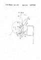
- FIG. 2 is an enlarged sectional view taken along the line II--II in FIG. 1, showing the state where the feed rollers are set in this embodiment;
- FIG. 3 is an enlarged sectional view showing the state where the feed rollers are set in this embodiment.
- FIG. 4 is an enlarged view in the direction indicated by the arrows from the line IV--IV in FIG. 1.
- FIG. 1 is a plan view showing the feed roller device of the typewriter according to the present invention.
- side frames 10 and 12 which are connected to each other by a pipe frame 14 being rectangular in cross section.
- a working rod 16 to be described hereinafter is rotatably supported across the side frames 10 and 12.
- FIG. 1 shows a pair of feed roller assemblies 18 and 20, which are arranged in parallel to the axial direction of a platen. Description will now be given of construction of the feed roller assemblies 18 and 20.
- a front feed roller row includes three small diameter feed rollers 22, 22 and 22, and a rotary shaft 24, on which are mounted these small diameter feed rollers 22, 22 and 22.
- a rear feed roller row includes three large diameter feed rollers 26, 26 and 26, and a rotary shaft 28, on which are mounted these large diameter feed rollers 26, 26 and 26.
- the rotary shaft 24 of the small diameter feed roller row and the rotary shaft 28 of the large diameter feed roller row are rotatably mounted at opposite ends thereof on arms 30 and 32. Consequently, it follows that the rollers 22 and 26 are rotatably mounted on the arms 30 and 32.
- a connecting rod 34 mounted at the center portions of the arms 30 and 32 is a connecting rod 34. Consequently, it follows that the arms 30 and 32 are connected to each other through the connecting rod 34.
- the rotary shaft 24 is mounted on the arms 30 and 32 in parallel to the rotary shaft 28, and further, the connecting rod 34 is mounted on the arms 30 and 32 in parallel to these rotary shafts 24 and 28.
- a pair of feed roller assemblies identical with each other are parallelly arranged as shown.
- FIG. 2 is an enlarged sectional view taken along the line II--II in FIG. 1.
- the arm 30 is formed with a slot 36, through which a working rod 16 is inserted. Consequently, it follows that the arm 30 is supported by the working rod 16.
- the other arm 32 is also formed with a slot 36, through which the working rod 16 is inserted to support the arm 32.
- a support bracket 38 is solidly secured to the bottom surface of the pipe frame 14.
- a projected member 40 is formed at the central portion of the support bracket 38 and the aforesaid working rod 16 extends through a hole 42 formed in this projected member 40.
- the support bracket 38 is provided at opposite ends thereof with projections 44 and 44.
- Rocking levers 46 and 46 are disposed at the central portions in the axial directions of the feed roller assemblies 18 and 20, respectively. As shown in FIG. 2, the rocking lever 46 is bent at one end 48 thereof into a U-shape to form a groove 50, through which is inserted a small diameter portion 52 formed at the central portion in the axial direction of the connecting rod 34.
- one end 48 of the rocking lever 46 is rotatably supported by the connecting rod 34. Further, an opening 54 is formed at the central portion of the rocking lever 46, and the projection 44 of the support bracket 38 is inserted through the opening 54, so that the rocking lever 46 can rock about a point P 1 of the projection 44.
- Formed at the other end of the rocking lever 46 is a recess 56, with which is engaged one end of a spring 58, the other end of which is solidly secured to the frame, not shown. The spring 58 urges the rocking lever 46 about the point P 1 in the clockwise direction.
- the working rod 16 is provided at the side thereof opposed to the upper edge portion 60 of the rocking lever 46 with a flat cut surface 62. Consequently, if the working rod 16 is turned as shown in FIG. 3, than a corner of the cut surface 62 of the working rod 16 abuts against the upper edge portion 60 of the rocking lever 46, whereby the rocking lever 46 is pressed down and rotate about the point P 1 against the urging force of the spring 58 as shown in FIG. 3, so that the feed rollers 22 and 26 leave the platen 59 to bring about the setoff state.
- a bent control lever 64 is mounted on the side frame in a manner to be rotatable about a pin 66.
- a grip portion 68 is formed at the upper end portion of the lever 64, and secured to the lower end portion thereof with a pin 70.
- Solidly secured to the end portion of the working rod 16 at the side of the side frame 12 as shown in FIG. 4 is the lower end portion of a link 72, in which a bent groove 74 is formed from the central portion to the upper portion thereof. Inserted through this groove 74 is the pin 70 secured to the lower end portion of the aforesaid lever 64.
- the cut surface 62 is inclined to press down the upper edge portion 60 of the rocking lever 46 against the urging force of the spring 58.
- the pin 70 secured to the lower end portion of the lever 64 slides in the groove 74 formed in the link 72 and moves to a position indicated by a two-dot chain line.
- the groove 74 of the link 72 is bent at this position of the pin 70 indicated by the two-dot chain line, whereby the pin 70 is engaged with the upper portion of the groove 74 as indicated by the two-dot chain line. Consequently, under this condition, the feed rollers are held in the setoff state.
- the feed rollers are in the setoff state, so that a sheet of paper can be set in the typewriter.
- the lever 64 shown in FIG. 4 is moved from the position indicated by the two-dot chain line to the position indicated by the solid line, then the working rod 16 turns to the position shown in FIG. 2, and the cut surface 62 leaves the upper edge portion 60 of the rocking lever 46, whereby the feed rollers 22 and 26 are urged by the urging force of the spring 58 toward the platen 59.
- the rocking levers 46 are disposed at the central portions of the feed roller assemblies 18 and 20 in the axial lines respectively, to urge the feed rollers 22 and 26 against the platen, so that the feed rollers can be urged against the platen 59 by the forces in uniform value. Since the springs for urging the feed rollers 22 and 26 against the platen 59 are provided on only two rocking levers 46, both springs can be easily adjusted in spring pressure.
- the mechanism for setting the feed rollers off the platen is of such an arrangement that flat cut surface 62 are formed on the working rod 16, and this cut surfaces 62 are adapted to press down the rocking levers 46 which urge the feed rollers 22 and 26 toward the platen 59, so that the mechanism for setting the feed rollers off the platen can be simplified in construction to a considerable extent.
- the two pairs of arms 30 and 32 are identical in configuration with one another, whereby all of these arms are manufactured in one die by press work, so that dimensional errors therebetween occurring during manufacture can be minimized, thereby enabling to make the urging forces of the feed rollers 22 and 26 against the platen 59 uniform.
- the abovedescribed case of the arms 30 and 32 is true of the case of the pair of rocking arms and the latter can also manufactured in one die, so that dimensional errors therebetween occurring during manufacture can be minimized.
Applications Claiming Priority (2)
| Application Number | Priority Date | Filing Date | Title |
|---|---|---|---|
| JP55-110951 | 1980-08-11 | ||
| JP11095180A JPS5738176A (en) | 1980-08-11 | 1980-08-11 | Feed roller for typewriter |
Related Parent Applications (1)
| Application Number | Title | Priority Date | Filing Date |
|---|---|---|---|
| US06523754 Continuation | 1983-08-16 |
Publications (1)
| Publication Number | Publication Date |
|---|---|
| US4527922A true US4527922A (en) | 1985-07-09 |
Family
ID=14548669
Family Applications (1)
| Application Number | Title | Priority Date | Filing Date |
|---|---|---|---|
| US06/637,526 Expired - Fee Related US4527922A (en) | 1980-08-11 | 1984-08-03 | Feed roller device of typewriter |
Country Status (3)
| Country | Link |
|---|---|
| US (1) | US4527922A (de) |
| JP (1) | JPS5738176A (de) |
| DE (1) | DE3131750C2 (de) |
Cited By (1)
| Publication number | Priority date | Publication date | Assignee | Title |
|---|---|---|---|---|
| EP0266139A1 (de) * | 1986-10-24 | 1988-05-04 | Oki Electric Industry Company, Limited | Andruckrollen-Betätigungsmechanismus für einen Drucker |
Families Citing this family (11)
| Publication number | Priority date | Publication date | Assignee | Title |
|---|---|---|---|---|
| JPS5993372A (ja) * | 1982-11-18 | 1984-05-29 | Brother Ind Ltd | プリンタの用紙送りリリ−ス機構 |
| FR2542254A1 (en) * | 1983-03-10 | 1984-09-14 | Sagem | Removable pressure roller system for printing machine |
| JPH0615250B2 (ja) * | 1983-04-12 | 1994-03-02 | キヤノン株式会社 | 紙送り機構 |
| JPS6026858U (ja) * | 1983-08-01 | 1985-02-23 | 松下電器産業株式会社 | 給紙装置 |
| JPS6032684A (ja) * | 1983-08-01 | 1985-02-19 | Matsushita Electric Ind Co Ltd | 給紙装置 |
| JPS60116487A (ja) * | 1983-11-30 | 1985-06-22 | Nec Home Electronics Ltd | プリンタの紙送り装置 |
| JPS60220774A (ja) * | 1984-04-17 | 1985-11-05 | Matsushita Electric Ind Co Ltd | 印字装置 |
| JPS63108746U (de) * | 1986-12-29 | 1988-07-13 | ||
| JP2630447B2 (ja) * | 1988-10-20 | 1997-07-16 | セイコープレシジョン株式会社 | プリンタの紙送り機構 |
| DE3939506A1 (de) * | 1989-05-22 | 1990-11-29 | Mannesmann Ag | Einrichtung fuer den papiertransport in druckern, insbesondere in matrixdruckern |
| IT1234288B (it) * | 1989-06-14 | 1992-05-14 | Olivetti & Co Spa | Dispositivo premicarta per macchine scriventi |
Citations (4)
| Publication number | Priority date | Publication date | Assignee | Title |
|---|---|---|---|---|
| US1062569A (en) * | 1910-02-18 | 1913-05-20 | Underwood Typewriter Co | Type-writing machine. |
| US1453577A (en) * | 1918-09-30 | 1923-05-01 | Corona Typewriter Co Inc | Typewriting machine |
| US2059214A (en) * | 1934-04-21 | 1936-11-03 | Remington Rand Inc | Paper feeding device |
| US2297490A (en) * | 1939-07-24 | 1942-09-29 | Martin Hans | Paper guide and feed for typewriters |
Family Cites Families (5)
| Publication number | Priority date | Publication date | Assignee | Title |
|---|---|---|---|---|
| US1315559A (en) * | 1919-09-09 | X x x ware | ||
| US1453581A (en) * | 1918-12-27 | 1923-05-01 | Corona Typewriter Co Inc | Typewriting machine |
| DE364059C (de) * | 1920-11-07 | 1922-11-16 | Triumph Werke Nuernberg Akt Ge | Papierfuehrungsvorrichtung |
| JPS422966Y1 (de) * | 1964-03-10 | 1967-02-22 | ||
| CH582070A5 (de) * | 1975-02-06 | 1976-11-30 | Hermes Precisa International |
-
1980
- 1980-08-11 JP JP11095180A patent/JPS5738176A/ja active Pending
-
1981
- 1981-08-11 DE DE3131750A patent/DE3131750C2/de not_active Expired
-
1984
- 1984-08-03 US US06/637,526 patent/US4527922A/en not_active Expired - Fee Related
Patent Citations (4)
| Publication number | Priority date | Publication date | Assignee | Title |
|---|---|---|---|---|
| US1062569A (en) * | 1910-02-18 | 1913-05-20 | Underwood Typewriter Co | Type-writing machine. |
| US1453577A (en) * | 1918-09-30 | 1923-05-01 | Corona Typewriter Co Inc | Typewriting machine |
| US2059214A (en) * | 1934-04-21 | 1936-11-03 | Remington Rand Inc | Paper feeding device |
| US2297490A (en) * | 1939-07-24 | 1942-09-29 | Martin Hans | Paper guide and feed for typewriters |
Non-Patent Citations (6)
| Title |
|---|
| "Frame for Paper Feed Rolls"; R. H. Marowski et al; IBM Technical Disclosure Bulletin, vol. 14, No. 3; 8/1971; p. 905. |
| "Paper Feed Mechanism"; E. R. Lloyd et al; IBM Technical Disclosure Bulletin; vol. 23, No. 2, pp. 678-679; Jul. 1980. |
| "Paper-Handling Apparatus for Typewriter & Printers"; R. J. Jenney et al; IBM Technical Disclosure Bulletin, vol. 20, No. 12; 5/1978; p. 5221. |
| Frame for Paper Feed Rolls ; R. H. Marowski et al; IBM Technical Disclosure Bulletin, vol. 14, No. 3; 8/1971; p. 905. * |
| Paper Feed Mechanism ; E. R. Lloyd et al; IBM Technical Disclosure Bulletin; vol. 23, No. 2, pp. 678 679; Jul. 1980. * |
| Paper Handling Apparatus for Typewriter & Printers ; R. J. Jenney et al; IBM Technical Disclosure Bulletin, vol. 20, No. 12; 5/1978; p. 5221. * |
Cited By (1)
| Publication number | Priority date | Publication date | Assignee | Title |
|---|---|---|---|---|
| EP0266139A1 (de) * | 1986-10-24 | 1988-05-04 | Oki Electric Industry Company, Limited | Andruckrollen-Betätigungsmechanismus für einen Drucker |
Also Published As
| Publication number | Publication date |
|---|---|
| DE3131750C2 (de) | 1986-04-03 |
| JPS5738176A (en) | 1982-03-02 |
| DE3131750A1 (de) | 1982-05-06 |
Similar Documents
| Publication | Publication Date | Title |
|---|---|---|
| US4527922A (en) | Feed roller device of typewriter | |
| US4611939A (en) | Sheet feeding device for an impact-type printer | |
| US4507666A (en) | Thermal head supporting mechanism | |
| US2750022A (en) | Type bar impact control | |
| GB2032347A (en) | Hand labellers and platens therefor | |
| US4176600A (en) | Type positioning mechanism for printing device | |
| US3585929A (en) | Platen assembly for check writers | |
| US3211271A (en) | Line find device | |
| JPS59223620A (ja) | リ−ドフレ−ム搬送機構 | |
| US3721186A (en) | Rockable impression device for a printing machine | |
| EP0266139B1 (de) | Andruckrollen-Betätigungsmechanismus für einen Drucker | |
| JPS6232863Y2 (de) | ||
| US5056944A (en) | Paper pressing arrangement for typewriters | |
| JPH0428776Y2 (de) | ||
| US3738267A (en) | Latching device | |
| JPH09123489A (ja) | サーマルプリンタの印字ヘッド機構 | |
| US3224547A (en) | Typewriter impression control | |
| JPS58126180A (ja) | 印字ヘツド位置決め機構 | |
| KR870000861Y1 (ko) | 타이프 라이터의 종이 압착 및 해제장치 | |
| JPS6222385Y2 (de) | ||
| JPH0518714B2 (de) | ||
| JPH0312535Y2 (de) | ||
| JPS58205783A (ja) | 印字機械における記録用紙の送り装置 | |
| JP2562303B2 (ja) | プリンタの紙送り機構 | |
| JPH0716208Y2 (ja) | タイムレコーダの印字装置 |
Legal Events
| Date | Code | Title | Description |
|---|---|---|---|
| REMI | Maintenance fee reminder mailed | ||
| LAPS | Lapse for failure to pay maintenance fees | ||
| STCH | Information on status: patent discontinuation |
Free format text: PATENT EXPIRED DUE TO NONPAYMENT OF MAINTENANCE FEES UNDER 37 CFR 1.362 |
|
| FP | Lapsed due to failure to pay maintenance fee |
Effective date: 19890709 |