US4409099A - Sieve deck for sifting machines - Google Patents
Sieve deck for sifting machines Download PDFInfo
- Publication number
- US4409099A US4409099A US06/243,964 US24396481A US4409099A US 4409099 A US4409099 A US 4409099A US 24396481 A US24396481 A US 24396481A US 4409099 A US4409099 A US 4409099A
- Authority
- US
- United States
- Prior art keywords
- sieve
- elements
- support structure
- corners
- sieve elements
- Prior art date
- Legal status (The legal status is an assumption and is not a legal conclusion. Google has not performed a legal analysis and makes no representation as to the accuracy of the status listed.)
- Expired - Fee Related
Links
Images


Classifications
-
- B—PERFORMING OPERATIONS; TRANSPORTING
- B07—SEPARATING SOLIDS FROM SOLIDS; SORTING
- B07B—SEPARATING SOLIDS FROM SOLIDS BY SIEVING, SCREENING, SIFTING OR BY USING GAS CURRENTS; SEPARATING BY OTHER DRY METHODS APPLICABLE TO BULK MATERIAL, e.g. LOOSE ARTICLES FIT TO BE HANDLED LIKE BULK MATERIAL
- B07B1/00—Sieving, screening, sifting, or sorting solid materials using networks, gratings, grids, or the like
- B07B1/46—Constructional details of screens in general; Cleaning or heating of screens
- B07B1/4609—Constructional details of screens in general; Cleaning or heating of screens constructional details of screening surfaces or meshes
- B07B1/4645—Screening surfaces built up of modular elements
Definitions
- the invention relates to a sieve deck for sifting machines, sifting boxes or the like.
- a sieve deck of this kind comprises a support structure and sieve elements releasably disposed thereupon and provided with a multiplicity of sieve openings. These sieve elements extend to form a continuous separation face and have the basic shape of a polygon, the sieve elements being secured on the support structure at least in the vicinity of some of their corners.
- the struts of the support structure must be adapted both in terms of the direction in which they extend and in their dimensions to the sides of the sieve elements which will rest upon them.
- the width of the support struts of the support structure must therefore not be below a certain given width, so that in the known embodiment the expense for materials used to make up the support structure cannot be reduced any further.
- the invention has the fundamental object of attaining a larger actually effective open surface area for sifting.
- the particular advantage of a sieve deck according to the invention is that the support of the sieve elements solely in the vicinity of their corners accordingly enables an enlargement of the actually effective open surface area for sifting, because the sieve openings are capable of extending as far as the rim of the individual sieve elements, or even beyond that. Because the support structure is shifted downward from the underside of the sieve elements and disposed at a distance therefrom, the passage through the sieve of the material to be sifted is not hindered even in the vicinity of those sieve openings which are located (viewed in the direction in which the material to be sifted will pass through the sieve) above the individual struts of the support structure. In order to prevent the effect of abrasion on the struts as a result of the sifted material, the struts of the support structure can be provided on their upper surface with a streamlined shape and/or a wear-prevention coating.
- the spacer elements may either be rigidly attached to the sieve elements or embodied as separate components which can be inserted between the sieve elements and the support structure. It is also possible to dispose the spacer elements rigidly on the support structure. In that case, the spacer elements may advantageously be embodied by sawhorse-type supports on the support structure.
- the streamlined shape of the upper surface of the support structure struts can be provided by embodying the upper surface of these struts as either oblique or convexly curved surfaces.
- the upper surfaces of the support structure struts may have the form of a peaked roof.
- a further advantageous embodiment of a sieve deck according to the invention is represented by the supporting of adjacent sieve elements each with their adjoining corners resting on a single spacer element.
- the spacer elements advantageously have a single reception opening on their upper surface for centrally securing all the adjacent corners of the respective sieve elements.
- the sieve elements are furthermore advantageously fixed in the reception openings of the spacer elements directly via stubs at the corners and/or via securing pins.
- the sieve elements are made of an elastic solid material having reinforcement embedded in it either entirely or in part. It is furthermore advantageous for the sieve elements to have sealing lips extending around the circumference of lateral abutting faces.
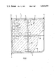
- FIG. 1 is a plan view of a sieve element having spacer elements and with the support structure shown in part for a sieve deck according to the invention
- FIG. 2 is a section taken through the sieve element along the line A--A of FIG. 1;
- FIG. 3 is a section taken through the corner fastening of adjacent sieve elements of a sieve deck according to the invention having spacer elements formed on the sieve elements;
- FIG. 4 is a section taken along the line A-B-C-D of FIG. 3;
- FIG. 5 is a section through a different corner fastening of adjacent sieve elements of a sieve deck according to the invention having separate spacer elements;
- FIG. 6 is a section taken through a further embodiment of a corner fastening of the sieve elements of a sieve deck according to the invention having spacer elements attached to the support structure;
- FIG. 7 shows cross-sectional shapes of the struts of the support structure of a sieve deck according to the invention
- FIG. 8 is a partial section taken through the rim of a sieve element for a sieve deck according to the invention.
- FIG. 9 is the plan view of a further sieve element for a sieve deck according to the invention having embedded reinforcement.
- FIG. 10 is the plan view of a different sieve element for a sieve deck according to the invention having embedded reinforcement.
- FIGS. 1 and 2 show the fundamental design of a sieve deck according to the invention. It is substantially made up of sieve elements 1, which extend to form a continuous separation face. To this end, the individual sieve elements 1 abut one another at the same level and without space between them, which is sufficiently well known and is therefore not shown in further detail in the drawing.
- Each individual sieve element has the fundamental shape of a regular polygon and in a preferred realization takes the form of a square, as is shown in the drawing. On this point, it is essential that the individual sieve elements be not only secured but also supported only in the vicinity of the corners of the respective polygon; that is, in the case where the basic shape is square, only in the vicinity of the four corners. If the sieve elements have a greater number of corners, then the support of the individual sieve elements can also be provided only at some of these corners. Thus it is possible to secure and support a hexagonal or octagonal sieve element only in the vicinity of every other corner.
- the sieve elements 1 substantially comprise rim ribs 2 and intersecting inner ribs 3, which enclose sieve openings 4.
- the sieve openings 4 have the same basic shape as the sieve element 1 itself. However, they may also have a shape different from that of the sieve element; in particular, they may take the shape of a slit or gap.
- the sieve elements 1 have stubs 6 at the underside, which protrude downward beyond the lower limiting face of the sieve elements 1.
- the sieve elements 1 are secured with these stubs 6 on their underside to a support structure 7 disposed therebelow, the connection of the sieve elements 1 with the support structure 7 being effected via spacer elements 8.
- These spacer elements 8 serve to provide a distance "A" between the underside of the sieve elements 1 and the upper side of the support structure 7.
- the sieve elements 1 may also be secured on the spacer elements 8 by some other means than by way of the stubs 6. In the exemplary embodiment shown in FIGS.
- the support structure is made up of tubular support struts onto which sawhorse-type supports 9 are placed, acting as spacer elements 8, in the vicinity of the adjacent corners 5 of the sieve elements 1.
- These sawhorse-type supports 9 have one or more reception openings 10 on their upper side, into which the stubs 6 on the underside of the sieve elements 1 are inserted and are fixed therein.
- all the stubs 6 in the vicinity of the adjoining corners of adjacent sieve elements 1 engage a single common reception opening 10 of the spacer elements 8.
- the stubs 6 of the sieve elements 1 have to this end the form of a quarter-cylinder or quarter-cylindrical tube, so that in the case where the basic shape of the sieve elements 1 is square, the four stubs 6 adjoining one another combine, at the adjoining corners 5 of the sieve elements 1, to form one complete cylinder or one complete cylindrical tube engaging the reception opening 10 of the associated sawhorse-type support 9.
- the fixation of the stubs 6 at the corners of the sieve element 1 in the reception openings 10 of the sawhorse-type supports 9 may be effected either by means of a pushbutton-type embodiment or by expansion pins which are to be inserted in addition.
- FIGS. 3 and 4 show sieve elements 1 for a sieve deck according to the invention having the spacer elements 8 on the underside molded directly on the sieve elements 1 in the form of protruding spacer feet 11.
- the height of the spacer feet 11 determines the distance "A" between the underside of the sieve elements 1 and the upper side of the support structure 7 of the sieve deck.
- the spacer feet 11 are embodied as quarters of tubular sheaths and have spreading tabs 12 on their lower end with which they are passed through securing openings 15 on the upper side of the associated struts of the support structure 7.
- a securing pin 13 is inserted into the passageway formed by the extended spacer feet 11.
- This securing pin 13 spreads apart the spreading tabs 12 and thus holds the sieve elements 1 securely on the support structure 7.
- the sieve elements 1 are also held securely on the support structure 7 in the vertical direction by means of a well-defined head 14 of the securing pin 13, which has been sunk into the upper side of the sieve elements 1.
- FIG. 5 shows a further realization of a sieve deck according to the invention, in which the sieve elements 1 are connected with the support structure 7 via spacer elements 8 embodied as separate components 16.
- the securing of the sieve elements 1, via the downwardly protruding stubs 6 at the corners, on the spacer components 16 may be effected in the same manner as the securing of the sieve elements 1 as shown in FIG. 3 with rigidly molded spacer elements 8 attached to the sieve element 1.
- the stubs themselves, with their free ends, constitute the spreading tabs 12 and receive the securing pin 13 in the passageway formed by extension.
- the separate spacer components 16 have a corresponding reception opening 17 at the top, through which the stubs 6 of the sieve elements 1 are passed.
- the securing of the spacer components 16 on the support structure 7 located below them may be effected via detent heads 18 molded onto the lower side which are inserted into corresponding fastening openings 19 of the support structure 7 in the manner of buttons in buttonholes.
- the spacer components 16 are efficiently made of an elastic material, such as plastic in particular, this being preferably the same material as that used to make the sieve elements 1.
- the securing pins 13 may be made of the same plastic material.
- the height of the spacer components 16 determines the essential distance "A" between the underside of the sieve elements 1 and the upper side of the support structure 7.
- FIG. 6 shows one realization of a sieve deck according to the invention, in which the spacer elements 8 are firmly attached to the framework of the support structure 7.
- the special feature of the support structure 7 used here is that its struts 20 are embodied by a vertically disposed square profile section. This makes it possible to make the upper sides 21 of the struts 20 of the support structure 7 oblique, taking the form of a peaked roof, so as to make it easier for the sifted material to slide away from the struts 20. As a result, first the abrasive stress exerted by the sifted material on the support structure is reduced to a minimum, and second the sifted material is prevented from leaving a residue on the upper side of the support structure 7.
- FIG. 7a shows once again the square cross-sectional profile for the struts 20 having upper sides 21 made oblique in the manner of a peaked roof.
- FIG. 7b likewise shows a strut 22 having upper sides 21 made oblique in the manner of a peaked roof. However, this is attained in this case by the placement of an L-bar at the top of a square profile section which is laid flat.
- FIG. 7c shows a strut 23 which has the cross-sectional profile of a cylindrical tube having a curved upper side 24. In like fashion, the strut 25 shown in FIG.
- the sieve elements 1 in a sieve deck according to the invention are supported on points, solely at their corners, there is the danger that open gaps can form between the lateral abutting faces 26 of the adjacently located sieve elements and toward the bottom, through which the sifted material can escape.
- the sieve elements 1 may have at least one sealing lip 27 extending all the way around their lateral abutting faces 26, as is shown in FIG. 8.
- FIG. 9 shows a sieve element such as that preferably used for a sieve deck of the type according to the invention. It is made of an elastic solid material which has been reinforced by an embedded reinforcement 28, 29.
- the reinforcement is made up first of an annular reinforcement 28 around the outside, which is located in the vicinity of the rim ribs 2 and extends substantially between the support corners 5 of the sieve elements 1.
- An embedded cruciform reinforcement 29 is disposed in the direction of the crosswise and lengthwise center of the sieve element 1. Both the outer reinforcement 28 and the inner, cruciform reinforcement 29 may be embedded either entirely or in part in the elastic solid material of which the sieve elements 1 are made.
- FIG. 10 shows a further realization of the sieve elements for a sieve deck according to the invention.
- the sieve elements 1 are made of elastic solid material having an outer, annular reinforcement 28 which extends between the support corners 5 of the sieve elements 1.
- the reinforcement 28 is shifted somewhat toward the inside, so that recesses are formed along the rims of the sieve elements 1 resulting in halves of outwardly-opening sieve openings 30.
- These halves of sieve openings 30 then, together with the half-openings 30 at the rims of adjoining sieve elements 1, combine to make one whole sieve opening, as shown in FIG. 10.
- a sieve surface is attained which has a uniform grid extending over all the sieve elements 1.
- the rim ribs 2 of the sieve elements 1 are embodied as being half the width of the inner ribs 3.
Landscapes
- Combined Means For Separation Of Solids (AREA)
Applications Claiming Priority (2)
| Application Number | Priority Date | Filing Date | Title |
|---|---|---|---|
| DE2926987 | 1979-07-04 | ||
| DE2926987A DE2926987B1 (de) | 1979-07-04 | 1979-07-04 | Siebmaschinen-Siebdeck |
Publications (1)
| Publication Number | Publication Date |
|---|---|
| US4409099A true US4409099A (en) | 1983-10-11 |
Family
ID=6074883
Family Applications (1)
| Application Number | Title | Priority Date | Filing Date |
|---|---|---|---|
| US06/243,964 Expired - Fee Related US4409099A (en) | 1979-07-04 | 1980-07-02 | Sieve deck for sifting machines |
Country Status (8)
| Country | Link |
|---|---|
| US (1) | US4409099A (fr) |
| EP (1) | EP0036858B1 (fr) |
| AU (1) | AU546016B2 (fr) |
| BR (1) | BR8008965A (fr) |
| CA (1) | CA1148503A (fr) |
| DE (1) | DE2926987B1 (fr) |
| WO (1) | WO1981000065A1 (fr) |
| ZA (1) | ZA804039B (fr) |
Cited By (27)
| Publication number | Priority date | Publication date | Assignee | Title |
|---|---|---|---|---|
| US4661245A (en) * | 1982-12-09 | 1987-04-28 | Fioris Pty Ltd. | Screening system |
| US4670136A (en) * | 1983-03-05 | 1987-06-02 | Isenmann, Drahterzeugnisse Gmbh | Screen surfacing with exchangeable screen elements |
| US4757664A (en) * | 1985-06-04 | 1988-07-19 | Screenex Wire Weaving Manufacturers (Proprietary) Limited | Wear resistant panel arrangement |
| US4819809A (en) * | 1985-09-09 | 1989-04-11 | Derrick Manufacturing Corporation | Reinforced polyurethane vibratory screen |
| US4857176A (en) * | 1986-08-04 | 1989-08-15 | Derrick Manufacturing Corporation | Reinforced molded polyurethane vibratory screen |
| US4863597A (en) * | 1988-04-19 | 1989-09-05 | W. S. Tyler, Incorporated | Dewatering device with screen assembly having releasable fastening means |
| US4871288A (en) * | 1986-03-13 | 1989-10-03 | Hein, Lehmann Ag | Screen lining |
| US4882044A (en) * | 1987-09-26 | 1989-11-21 | Polydeck Screen Corporation | Screening arrangement |
| US4909929A (en) * | 1988-10-24 | 1990-03-20 | Norris Screen & Manufacturing, Inc. | Interlocking clamping system |
| WO1990005594A1 (fr) * | 1988-11-23 | 1990-05-31 | Western Wire Works, Incorporated | Systeme modulaire |
| AU601052B2 (en) * | 1987-09-26 | 1990-08-30 | Polydeck Screen Corporation | Screening arrangement |
| US4960510A (en) * | 1987-06-26 | 1990-10-02 | Steinhaus Gmbh | Screening apparatus having a screen grid with a plurality of exchangeable screen elements |
| US5049262A (en) * | 1988-11-23 | 1991-09-17 | Galton Zanley F | Modular system |
| US5213217A (en) * | 1991-10-25 | 1993-05-25 | Galton Zanley F | Screening system and method for screening particulate material |
| US5292432A (en) * | 1991-12-18 | 1994-03-08 | Filterwerk Mann & Hummel Gmbh | Filter for fluids |
| US5385242A (en) * | 1993-02-17 | 1995-01-31 | Freissle; Manfred F. A. | Screening arrangement |
| US5755334A (en) * | 1996-03-19 | 1998-05-26 | Illinois Tool Works Inc. | Method and apparatus for mounting a panel on a support member |
| WO2000064599A2 (fr) * | 1999-04-26 | 2000-11-02 | Durex Products, Inc. | Tamis pour cribleuse |
| US6206200B1 (en) | 1999-01-19 | 2001-03-27 | United States Filter Corporation | Mounting system for modular panels used in a screen deck |
| US6253926B1 (en) * | 1996-09-05 | 2001-07-03 | Lettela Pty Limited | Modular screen panel |
| US6258261B1 (en) * | 1998-08-31 | 2001-07-10 | Mse Technology Applications, Inc. | Honeycomb cell structure for fluid-solid reactor |
| US6267246B1 (en) * | 2000-02-14 | 2001-07-31 | Western Wire Works, Inc. | Screening system for screening or diverting particulate material |
| US20030038060A1 (en) * | 2001-08-07 | 2003-02-27 | Freissle Manfred Franz Axel | Screening arrangement |
| US6634505B1 (en) * | 1999-04-26 | 2003-10-21 | Durex Products, Inc. | Sieve bed for a sifting machine |
| US20060196416A1 (en) * | 1993-05-25 | 2006-09-07 | Shutic Jeffrey R | Vehicle powder coating system |
| US20080121568A1 (en) * | 2006-11-28 | 2008-05-29 | Johnson Screens (Australia) Pty Ltd. | Screening module retaining assembly |
| WO2024059918A1 (fr) * | 2022-09-19 | 2024-03-28 | Haver & Boecker Telas Ltda | Mailles modulaires améliorées faisant partie d'un composant de tamis vibrant qui intègre un équipement de tri cubique et lamellaire pour trier des matériaux d'exploitation minière, système de fixation conjointe d'unités adjacentes de mailles modulaires améliorées à la base structurale d'un composant de tamis vibrant, et procédure de montage/démontage de cette base |
Families Citing this family (6)
| Publication number | Priority date | Publication date | Assignee | Title |
|---|---|---|---|---|
| DE3544752C1 (de) * | 1985-12-18 | 1990-12-06 | Steinhaus Gmbh | Verfahren zur Herstellung von Siebbauteilen unterschiedlicher Laenge fuer Systemsiebboeden und Siebbauteil |
| DE3732031C3 (de) * | 1987-06-26 | 1994-12-15 | Steinhaus Gmbh | Systemsiebboden mit einer Vielzahl auswechselbarer Siebelemente |
| DE19860612B4 (de) * | 1998-12-29 | 2007-04-12 | Ludwig Krieger Draht- Und Kunststofferzeugnisse Gmbh | Siebbelag für Schwingsiebe |
| CA2375105C (fr) | 1999-05-31 | 2008-09-09 | David Llewellen Owen | Ecrans |
| DE102018205997B4 (de) * | 2018-04-19 | 2021-08-19 | Thyssenkrupp Ag | Siebsystem mit genuteten Traversen |
| EP4101549A1 (fr) * | 2021-06-07 | 2022-12-14 | Sandvik SRP AB | Panneau de criblage à monter sur une surface criblante et matériaux de criblage en vrac |
Citations (7)
| Publication number | Priority date | Publication date | Assignee | Title |
|---|---|---|---|---|
| US2883051A (en) * | 1955-08-06 | 1959-04-21 | Kloeckner Humboldt Deutz Ag | Shaking sieve device with transverse girders for the sieve plate |
| US3905897A (en) * | 1973-07-09 | 1975-09-16 | Simplicity Eng Co | Material classifying apparatus |
| GB1483217A (en) * | 1974-08-02 | 1977-08-17 | Hein Lehmann Ag | Screen panel assembled from individual segments made of elastic materials |
| US4062769A (en) * | 1974-12-19 | 1977-12-13 | Durex Products, Inc. | Elastomer screen units for shaker-screen bodies |
| DE2749530A1 (de) * | 1976-11-24 | 1978-06-01 | Crompton & Knowles Corp | Fluid-behandlungsvorrichtung fuer textilfasermaterial |
| US4141821A (en) * | 1976-05-21 | 1979-02-27 | Firma Steinhaus Gmbh | Screening deck assembly |
| DE2849838B1 (de) * | 1978-11-17 | 1979-09-13 | Hein Lehmann Ag | Siebboden |
Family Cites Families (8)
| Publication number | Priority date | Publication date | Assignee | Title |
|---|---|---|---|---|
| DE906401C (de) * | 1952-06-19 | 1954-03-11 | Kloeckner Humboldt Deutz Ag | Sieb, dessen Siebbelag auf einem Tragrost des Siebkastens ruht |
| DE1209856B (de) * | 1964-10-21 | 1966-01-27 | Albert Wehner | Siebboden |
| GB1173666A (en) * | 1967-01-23 | 1969-12-10 | Martin Anthony Harvey | Improvements relating to Cavity or Elevated Floors |
| AU417359B2 (en) * | 1967-10-19 | 1971-09-22 | Becton, Dickinson And Company | Filter framing system |
| GB1520886A (en) * | 1975-08-14 | 1978-08-09 | Simplicity Eng Co | Material classifying apparatus |
| DE2632511C3 (de) * | 1976-07-20 | 1983-12-15 | Steinhaus GmbH, 4330 Mülheim | Siebfeld |
| DE2736662B2 (de) * | 1977-08-13 | 1979-06-13 | Hein, Lehmann Ag, 4000 Duesseldorf | Siebboden |
| DE2754044B1 (de) * | 1977-12-05 | 1979-04-19 | Willi-Klaus Kinker | Industrie-Siebboden zur Aufbereitung von Schuettguetern |
-
1979
- 1979-07-04 DE DE2926987A patent/DE2926987B1/de not_active Ceased
-
1980
- 1980-07-02 US US06/243,964 patent/US4409099A/en not_active Expired - Fee Related
- 1980-07-02 WO PCT/DE1980/000095 patent/WO1981000065A1/fr not_active Application Discontinuation
- 1980-07-02 AU AU61207/80A patent/AU546016B2/en not_active Ceased
- 1980-07-02 BR BR8008965A patent/BR8008965A/pt unknown
- 1980-07-03 CA CA000355279A patent/CA1148503A/fr not_active Expired
- 1980-07-04 ZA ZA00804039A patent/ZA804039B/xx unknown
-
1981
- 1981-01-26 EP EP80901265A patent/EP0036858B1/fr not_active Expired
Patent Citations (7)
| Publication number | Priority date | Publication date | Assignee | Title |
|---|---|---|---|---|
| US2883051A (en) * | 1955-08-06 | 1959-04-21 | Kloeckner Humboldt Deutz Ag | Shaking sieve device with transverse girders for the sieve plate |
| US3905897A (en) * | 1973-07-09 | 1975-09-16 | Simplicity Eng Co | Material classifying apparatus |
| GB1483217A (en) * | 1974-08-02 | 1977-08-17 | Hein Lehmann Ag | Screen panel assembled from individual segments made of elastic materials |
| US4062769A (en) * | 1974-12-19 | 1977-12-13 | Durex Products, Inc. | Elastomer screen units for shaker-screen bodies |
| US4141821A (en) * | 1976-05-21 | 1979-02-27 | Firma Steinhaus Gmbh | Screening deck assembly |
| DE2749530A1 (de) * | 1976-11-24 | 1978-06-01 | Crompton & Knowles Corp | Fluid-behandlungsvorrichtung fuer textilfasermaterial |
| DE2849838B1 (de) * | 1978-11-17 | 1979-09-13 | Hein Lehmann Ag | Siebboden |
Cited By (50)
| Publication number | Priority date | Publication date | Assignee | Title |
|---|---|---|---|---|
| US4661245A (en) * | 1982-12-09 | 1987-04-28 | Fioris Pty Ltd. | Screening system |
| DE3390381C2 (de) * | 1982-12-09 | 1992-09-03 | Fioris Pty Ltd | Siebvorrichtung, umfassend eine Vielzahl vonSiebbausteinen |
| US4670136A (en) * | 1983-03-05 | 1987-06-02 | Isenmann, Drahterzeugnisse Gmbh | Screen surfacing with exchangeable screen elements |
| AU569281B2 (en) * | 1983-03-05 | 1988-01-28 | Hein, Lehmann Trenn-Und Fordertechnik Gmbh | Screen surfacing with exchangeable screen elements |
| US4757664A (en) * | 1985-06-04 | 1988-07-19 | Screenex Wire Weaving Manufacturers (Proprietary) Limited | Wear resistant panel arrangement |
| US4819809A (en) * | 1985-09-09 | 1989-04-11 | Derrick Manufacturing Corporation | Reinforced polyurethane vibratory screen |
| US4871288A (en) * | 1986-03-13 | 1989-10-03 | Hein, Lehmann Ag | Screen lining |
| US4857176A (en) * | 1986-08-04 | 1989-08-15 | Derrick Manufacturing Corporation | Reinforced molded polyurethane vibratory screen |
| US4960510A (en) * | 1987-06-26 | 1990-10-02 | Steinhaus Gmbh | Screening apparatus having a screen grid with a plurality of exchangeable screen elements |
| AU601052B2 (en) * | 1987-09-26 | 1990-08-30 | Polydeck Screen Corporation | Screening arrangement |
| US4882044A (en) * | 1987-09-26 | 1989-11-21 | Polydeck Screen Corporation | Screening arrangement |
| US4863597A (en) * | 1988-04-19 | 1989-09-05 | W. S. Tyler, Incorporated | Dewatering device with screen assembly having releasable fastening means |
| US4909929A (en) * | 1988-10-24 | 1990-03-20 | Norris Screen & Manufacturing, Inc. | Interlocking clamping system |
| WO1990005594A1 (fr) * | 1988-11-23 | 1990-05-31 | Western Wire Works, Incorporated | Systeme modulaire |
| US5049262A (en) * | 1988-11-23 | 1991-09-17 | Galton Zanley F | Modular system |
| AU629881B2 (en) * | 1988-11-23 | 1992-10-15 | Western Wire Works, Incorporated | Modular system |
| US5213217A (en) * | 1991-10-25 | 1993-05-25 | Galton Zanley F | Screening system and method for screening particulate material |
| US5372261A (en) * | 1991-10-25 | 1994-12-13 | Western Wire Works, Inc. | System and method for screening or diverting particulate material |
| US5292432A (en) * | 1991-12-18 | 1994-03-08 | Filterwerk Mann & Hummel Gmbh | Filter for fluids |
| US5385242A (en) * | 1993-02-17 | 1995-01-31 | Freissle; Manfred F. A. | Screening arrangement |
| US20070215042A1 (en) * | 1993-05-25 | 2007-09-20 | Shutic Jeffrey R | Vehicle powder coating system |
| US20060196416A1 (en) * | 1993-05-25 | 2006-09-07 | Shutic Jeffrey R | Vehicle powder coating system |
| US5755334A (en) * | 1996-03-19 | 1998-05-26 | Illinois Tool Works Inc. | Method and apparatus for mounting a panel on a support member |
| US6253926B1 (en) * | 1996-09-05 | 2001-07-03 | Lettela Pty Limited | Modular screen panel |
| US6258261B1 (en) * | 1998-08-31 | 2001-07-10 | Mse Technology Applications, Inc. | Honeycomb cell structure for fluid-solid reactor |
| US6206200B1 (en) | 1999-01-19 | 2001-03-27 | United States Filter Corporation | Mounting system for modular panels used in a screen deck |
| WO2000064599A3 (fr) * | 1999-04-26 | 2003-02-06 | Roland E Kueper | Tamis pour cribleuse |
| US7273151B2 (en) | 1999-04-26 | 2007-09-25 | Durex Products, Inc. | Sieve bed for a sifting machine |
| US6634505B1 (en) * | 1999-04-26 | 2003-10-21 | Durex Products, Inc. | Sieve bed for a sifting machine |
| US20040074820A1 (en) * | 1999-04-26 | 2004-04-22 | Kirk Sawall | Sieve bed for a sifting machine |
| WO2000064599A2 (fr) * | 1999-04-26 | 2000-11-02 | Durex Products, Inc. | Tamis pour cribleuse |
| US20020046964A1 (en) * | 2000-02-14 | 2002-04-25 | Russell Lynn A. | Module for screening or diverting particulate material and method of producing the module |
| US20040074821A1 (en) * | 2000-02-14 | 2004-04-22 | Russell Lynn A. | Module for screening or diverting particulate material & method of producing the module |
| US6267246B1 (en) * | 2000-02-14 | 2001-07-31 | Western Wire Works, Inc. | Screening system for screening or diverting particulate material |
| US7090083B2 (en) | 2000-02-14 | 2006-08-15 | Western Wire Works, Inc. | Module for screening or diverting particulate material and method of producing the module |
| US7240801B2 (en) | 2001-08-07 | 2007-07-10 | Manfred Franz Axel Freissle | Screening arrangement |
| US20100025307A1 (en) * | 2001-08-07 | 2010-02-04 | Manfred Franz Axel Freissle | Screening Arrangement |
| US6957741B2 (en) | 2001-08-07 | 2005-10-25 | Manfred Franz Axel Freissle | Screening arrangement |
| US20050040083A1 (en) * | 2001-08-07 | 2005-02-24 | Freissle Manfred Franz Axel | Screening arrangement |
| US20030038060A1 (en) * | 2001-08-07 | 2003-02-27 | Freissle Manfred Franz Axel | Screening arrangement |
| US20070284292A1 (en) * | 2001-08-07 | 2007-12-13 | Freissle Manfred Franz A | Screening Arrangement |
| US20080047877A1 (en) * | 2001-08-07 | 2008-02-28 | Freissle Manfred Franz A | Screening Arrangement |
| US8025153B2 (en) | 2001-08-07 | 2011-09-27 | Manfred Franz Axel Freissle | Screening arrangement |
| US7604127B2 (en) | 2001-08-07 | 2009-10-20 | Manfred Franz Axel Freissle | Screening arrangement |
| US7621406B2 (en) | 2001-08-07 | 2009-11-24 | Polydeck Screen Corporation | Conversion kit for particulate screening system and related implementation methods |
| US20060180510A1 (en) * | 2001-08-07 | 2006-08-17 | Polydeck Screen Corporation | Conversion kit for particulate screening system and related implementation methods |
| AU2006243879B2 (en) * | 2006-11-28 | 2011-07-07 | Flsmidth A/S | A screening module retaining assembly |
| US20080121568A1 (en) * | 2006-11-28 | 2008-05-29 | Johnson Screens (Australia) Pty Ltd. | Screening module retaining assembly |
| US8123043B2 (en) * | 2006-11-28 | 2012-02-28 | Ludowici Australia Pty Ltd. | Screening module retaining assembly |
| WO2024059918A1 (fr) * | 2022-09-19 | 2024-03-28 | Haver & Boecker Telas Ltda | Mailles modulaires améliorées faisant partie d'un composant de tamis vibrant qui intègre un équipement de tri cubique et lamellaire pour trier des matériaux d'exploitation minière, système de fixation conjointe d'unités adjacentes de mailles modulaires améliorées à la base structurale d'un composant de tamis vibrant, et procédure de montage/démontage de cette base |
Also Published As
| Publication number | Publication date |
|---|---|
| WO1981000065A1 (fr) | 1981-01-22 |
| DE2926987B1 (de) | 1981-01-15 |
| ZA804039B (en) | 1981-06-24 |
| AU6120780A (en) | 1981-02-03 |
| BR8008965A (pt) | 1981-10-20 |
| AU546016B2 (en) | 1985-08-08 |
| EP0036858B1 (fr) | 1984-04-04 |
| CA1148503A (fr) | 1983-06-21 |
| EP0036858A1 (fr) | 1981-10-07 |
Similar Documents
| Publication | Publication Date | Title |
|---|---|---|
| US4409099A (en) | Sieve deck for sifting machines | |
| US4141821A (en) | Screening deck assembly | |
| US5333425A (en) | Tension membrane structure wrinkle elimination | |
| EP0891819B1 (fr) | Appareil de tamisage | |
| AU608392B2 (en) | Screening arrangement | |
| US4882044A (en) | Screening arrangement | |
| US4960510A (en) | Screening apparatus having a screen grid with a plurality of exchangeable screen elements | |
| GB1600604A (en) | Support frame for a screeing machine | |
| US4504288A (en) | Tubular-filter device with compressed-air cleanout | |
| GB1479181A (en) | Pallet of synthetic material | |
| US4762610A (en) | Screening arrangement | |
| US2790400A (en) | Skylight dome construction | |
| US4278535A (en) | Screen decks | |
| US5360541A (en) | Modular device for the ease of use and installation of filtration textiles | |
| US5363970A (en) | Screening arrangement | |
| SE8300121D0 (sv) | Siktnet | |
| EP0032436A1 (fr) | Appareil de criblage | |
| DE19837077A1 (de) | Bewehrungskorb und dessen Anordnung für die Herstellung von Stahlbeton-Hohlkörperplatten | |
| GB2092917A (en) | Screens | |
| US3428184A (en) | Screens for removal of liquid from sludge materials | |
| US3608719A (en) | Self-supporting screens for stone, ore and like material | |
| US2520998A (en) | Reinforcing means for bottle containing crates | |
| RU97107738A (ru) | Сепаратор сыпучих материалов | |
| RU2003120742A (ru) | Пневмокаркасное сооружение | |
| UA75452C2 (en) | Dome-like structure |
Legal Events
| Date | Code | Title | Description |
|---|---|---|---|
| AS | Assignment |
Owner name: STEINHAUS GMBH, PLATANENALLEE 46, 4330 MULHEIM, BU Free format text: ASSIGNMENT OF ASSIGNORS INTEREST.;ASSIGNOR:WOLFF KURT;REEL/FRAME:003884/0059 Effective date: 19810428 Owner name: STEINHAUS GMBH, PLATANENALLEE 46, 4330 MULHEIM, BU Free format text: ASSIGNMENT OF ASSIGNORS INTEREST;ASSIGNOR:WOLFF KURT;REEL/FRAME:003884/0059 Effective date: 19810428 |
|
| LAPS | Lapse for failure to pay maintenance fees | ||
| FP | Lapsed due to failure to pay maintenance fee |
Effective date: 19951011 |
|
| STCH | Information on status: patent discontinuation |
Free format text: PATENT EXPIRED DUE TO NONPAYMENT OF MAINTENANCE FEES UNDER 37 CFR 1.362 |