US4871288A - Screen lining - Google Patents
Screen lining Download PDFInfo
- Publication number
- US4871288A US4871288A US07/018,286 US1828687A US4871288A US 4871288 A US4871288 A US 4871288A US 1828687 A US1828687 A US 1828687A US 4871288 A US4871288 A US 4871288A
- Authority
- US
- United States
- Prior art keywords
- bar
- plastic section
- bolts
- projections
- upper region
- Prior art date
- Legal status (The legal status is an assumption and is not a legal conclusion. Google has not performed a legal analysis and makes no representation as to the accuracy of the status listed.)
- Expired - Fee Related
Links
- 238000003780 insertion Methods 0.000 claims description 3
- 230000037431 insertion Effects 0.000 claims description 3
- 230000015572 biosynthetic process Effects 0.000 claims 4
- 238000005755 formation reaction Methods 0.000 claims 4
- 230000000694 effects Effects 0.000 abstract description 4
- 230000014759 maintenance of location Effects 0.000 description 2
- 239000000463 material Substances 0.000 description 2
- 238000010276 construction Methods 0.000 description 1
- 230000001419 dependent effect Effects 0.000 description 1
- 239000002184 metal Substances 0.000 description 1
- 238000012216 screening Methods 0.000 description 1
Images
Classifications
-
- B—PERFORMING OPERATIONS; TRANSPORTING
- B07—SEPARATING SOLIDS FROM SOLIDS; SORTING
- B07B—SEPARATING SOLIDS FROM SOLIDS BY SIEVING, SCREENING, SIFTING OR BY USING GAS CURRENTS; SEPARATING BY OTHER DRY METHODS APPLICABLE TO BULK MATERIAL, e.g. LOOSE ARTICLES FIT TO BE HANDLED LIKE BULK MATERIAL
- B07B1/00—Sieving, screening, sifting, or sorting solid materials using networks, gratings, grids, or the like
- B07B1/46—Constructional details of screens in general; Cleaning or heating of screens
- B07B1/4609—Constructional details of screens in general; Cleaning or heating of screens constructional details of screening surfaces or meshes
- B07B1/4645—Screening surfaces built up of modular elements
Definitions
- the invention relates to a screen lining with screen elements arranged next to one another and fastened to sections of a supporting substructure by means of additional plastic sections which hold two lateral edges of adjacent screen elements, run parallel above the sections of the substructure and on their underside have projections fastened with a locking effect to the sections of the substructure.
- the object of the invention is to improve a screen lining of the type mentioned in the introduction, so that a secure retention is provided even when the orifices in the substructure have been widened.
- this object is achieved in that the plastic sections have at intervals centrally vertical orifices, into which bolts can be inserted from above with a locking effect, the bolt head forming a portion of that region of the plastic section which holds two lateral edges of adjacent screen elements, and in that the orifices pass coaxially through the projections and extend into the sections of the substructure.
- the shank of the bolt engaging into the plastic section widens out the region of the plastic section located in the orifice of the substructure, so that the plastic section is held securely, even when the orifices in the substructure have been opened out. Furthermore, the advantage of this construction is that the bolts are self-tightening, so that when play occurs the gap is filled.
- the bolt head is inserted into the plastic section, without forming a projection, so that it is not exposed to increased wear. Also, the screening material is not retarded by the head.
- the bolt head forms a horizontal portion of the upper region of the plastic section, and the plastic section has a corresponding recess at this point.
- the bolt head if it is of sufficient size, fits especially into the plastic section.
- the shank wall of the bolt is made sawtooth-shaped.
- the orifice can have a wall sawtooth-shaped to correspond to the bolt shank wall.
- a secure and simple fastening of the screen elements by means of the bolt head is obtained if the bolt head in the form of a part section has a mushroom-shaped cross-section. It is particularly advantageous if the bolt is made of plastic.
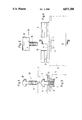
- FIG. 1 shows an end view of the bolt
- FIG. 2 shows a side view of the bolt
- FIG. 3 shows a section according to III--III in FIG. 4;
- FIG. 4 shows a side view of the substructure with a plastic section attached and with the bolt removed.
- a screen lining is composed of individual rectangular screen elements 1 consisting of plastic. These screen elements 1 have, in their lateral end faces 2, groove-shaped longitudinal recesses 3 which are held by the upper region 4 of a plastic section 5. For this purpose, the cross-section of the upper region 4 is made mushroom-shaped.
- the plastic section 5 rests on the top side of L-shaped horizontal metal sections 6 of the substructure.
- the sections 5 extend parallel to the sections 6 and on their underside have stud-like cylindrical projections 7 inserted into bores or orifices 8 in the section 6.
- Each projection 7 has in the centre an orifice 9 which passes through it vertically and narrows conically downwards, and the wall of which is made sawtooth-shaped.
- a bolt 10 can be inserted into the orifice 9 from above, its approximately cylindrical shank 11 being made sawtooth-shaped on the outside, so that it can engage into the sawtooth-shaped wall of the orifice 9 and be held positively. Since the orifice 9 narrows conically downwards, the degree of expansion of the projection 7 is dependent on the depth of insertion of the bolt 10.
- the bolt 10 has, on its top side, a head 12 which corresponds in shape to a portion of the upper mushroom-shaped region 4 of the section 5.
- the section 5 has in the upper region, above the orifice 9, a rectangular recess 13 which the head 12 fills completely after the bolt has been inserted.
- the bolt 10 preferably consists of the same plastic material as the section 5.
- the shank 11 of the bolt 10 can narrow conically downwards.
- the head 12, instead of having a mushroom-shaped cross-section, can also be made sawtooth-shaped, in order to engage into a correspondingly sawtooth-shaped longitudinal recess in the end face of the screen element 1.
Landscapes
- Image-Pickup Tubes, Image-Amplification Tubes, And Storage Tubes (AREA)
- Photoreceptors In Electrophotography (AREA)
- Combined Means For Separation Of Solids (AREA)
- Gas-Filled Discharge Tubes (AREA)
- Road Paving Structures (AREA)
- Lining And Supports For Tunnels (AREA)
Abstract
Description
Claims (5)
Applications Claiming Priority (2)
| Application Number | Priority Date | Filing Date | Title |
|---|---|---|---|
| EP86103385A EP0236530B1 (en) | 1986-03-13 | 1986-03-13 | Screen bottom |
| EP86103385 | 1986-03-13 |
Publications (1)
| Publication Number | Publication Date |
|---|---|
| US4871288A true US4871288A (en) | 1989-10-03 |
Family
ID=8194963
Family Applications (1)
| Application Number | Title | Priority Date | Filing Date |
|---|---|---|---|
| US07/018,286 Expired - Fee Related US4871288A (en) | 1986-03-13 | 1987-02-24 | Screen lining |
Country Status (6)
| Country | Link |
|---|---|
| US (1) | US4871288A (en) |
| EP (1) | EP0236530B1 (en) |
| AT (1) | ATE47335T1 (en) |
| AU (1) | AU591970B2 (en) |
| DE (1) | DE3666365D1 (en) |
| ZA (1) | ZA871234B (en) |
Cited By (24)
| Publication number | Priority date | Publication date | Assignee | Title |
|---|---|---|---|---|
| US5112475A (en) * | 1990-08-06 | 1992-05-12 | Conn-Weld Industries, Inc. | Panel mounting system |
| US5213217A (en) * | 1991-10-25 | 1993-05-25 | Galton Zanley F | Screening system and method for screening particulate material |
| US5361911A (en) * | 1994-04-14 | 1994-11-08 | Miller Wire Works, Inc. | Screening panel attachment system |
| US5377846A (en) * | 1989-08-25 | 1995-01-03 | Western Wire Works, Inc. | Particle screening system |
| US5464101A (en) * | 1993-06-23 | 1995-11-07 | Freissle; Manfred F. A. | Screening arrangement |
| US5755334A (en) * | 1996-03-19 | 1998-05-26 | Illinois Tool Works Inc. | Method and apparatus for mounting a panel on a support member |
| US5829599A (en) * | 1995-08-31 | 1998-11-03 | Lettela Proprietary Limited | Screening apparatus |
| WO2000053343A1 (en) * | 1999-03-08 | 2000-09-14 | Ludowici Mineral Processing Equipment Pty Ltd | Screening apparatus |
| WO2000064599A2 (en) * | 1999-04-26 | 2000-11-02 | Durex Products, Inc. | Sieve bed for a sifting machine |
| US6206200B1 (en) | 1999-01-19 | 2001-03-27 | United States Filter Corporation | Mounting system for modular panels used in a screen deck |
| US6267246B1 (en) * | 2000-02-14 | 2001-07-31 | Western Wire Works, Inc. | Screening system for screening or diverting particulate material |
| US20030038060A1 (en) * | 2001-08-07 | 2003-02-27 | Freissle Manfred Franz Axel | Screening arrangement |
| US6634505B1 (en) * | 1999-04-26 | 2003-10-21 | Durex Products, Inc. | Sieve bed for a sifting machine |
| AU773756B2 (en) * | 1999-03-08 | 2004-06-03 | Ludowici Mineral Processing Equipment Pty Ltd | Screening apparatus |
| US20060180511A1 (en) * | 2003-02-04 | 2006-08-17 | Schulte David L Jr | Interconnected screens for vibratory separators |
| US20060196813A1 (en) * | 2005-02-22 | 2006-09-07 | Ludwig Krieger Draht-Und Kunststofferzeugnisse Gmbh | Support beam for sieve panel |
| AU2003204125B2 (en) * | 2002-03-21 | 2007-09-13 | Schenck Process Australia Pty Ltd | Ore Screening Panel Fixing System |
| US20080121568A1 (en) * | 2006-11-28 | 2008-05-29 | Johnson Screens (Australia) Pty Ltd. | Screening module retaining assembly |
| US20100044281A1 (en) * | 2006-12-22 | 2010-02-25 | Johnson Sceens (Australia) 4034 | Screening panel securing system |
| US20120020725A1 (en) * | 2010-07-22 | 2012-01-26 | Chia-Yu Liu | Furniture connector |
| US20140061415A1 (en) * | 2011-05-05 | 2014-03-06 | Igus Gmbh | Retainer for laterally fastening a guide groove for energy supply chains and retaining system having said retainer |
| US20160096199A1 (en) * | 2013-06-17 | 2016-04-07 | Schenck Process Gmbh | Screen lining |
| US10201835B1 (en) * | 2015-12-18 | 2019-02-12 | Edwin C. Bailey | Mounting System for a wire screen panel |
| US11549531B2 (en) * | 2018-09-13 | 2023-01-10 | Penn Engineering & Manufacturing Corp. | Multi-clinch fastener insert |
Families Citing this family (3)
| Publication number | Priority date | Publication date | Assignee | Title |
|---|---|---|---|---|
| DE3703221A1 (en) * | 1987-02-04 | 1988-08-18 | Wahl Verschleiss Tech | METHOD FOR PRODUCING WEAR CLAIMS, A VARIETY OF SCREENS CONTAINING SCREEN OPENINGS |
| US5664685A (en) * | 1995-06-01 | 1997-09-09 | Manfred Franz Axel Freissle | Screening arrangement |
| AU711096B2 (en) * | 1996-07-17 | 1999-10-07 | Freissle, Manfred Franz Axel | Screening arrangement |
Citations (23)
| Publication number | Priority date | Publication date | Assignee | Title |
|---|---|---|---|---|
| US1934232A (en) * | 1932-02-11 | 1933-11-07 | Keuffel & Esser Co | Slide rule |
| US2394443A (en) * | 1942-11-09 | 1946-02-05 | Jr Emile S Guignon | Plural-unit portable building |
| US2448351A (en) * | 1946-01-23 | 1948-08-31 | Abbott P Brush | Tapped fastener |
| GB907232A (en) * | 1959-01-07 | 1962-10-03 | Illinois Tool Works | Fastener units |
| US3153975A (en) * | 1954-01-21 | 1964-10-27 | Illinois Tool Works | Fastener unit |
| GB1322014A (en) * | 1970-05-09 | 1973-07-04 | Tufdura Ltd | Resilient screen plate for grading particulate materials |
| US3795311A (en) * | 1973-03-23 | 1974-03-05 | Universal Oil Prod Co | Mounting assembly for vibrating screen deck |
| US3988808A (en) * | 1975-08-08 | 1976-11-02 | Hartwell Corporation | Readily mounted separable fastener |
| DE2736662A1 (en) * | 1977-08-13 | 1979-02-15 | Hein Lehmann Ag | Sieve base with elastic detachable strip sieve elements - has fastening battens connecting longitudinal edges of elements to lightweight support structure |
| US4141821A (en) * | 1976-05-21 | 1979-02-27 | Firma Steinhaus Gmbh | Screening deck assembly |
| US4276806A (en) * | 1978-07-13 | 1981-07-07 | Itw De France | Self-retained and reusable fastener |
| US4358234A (en) * | 1979-08-29 | 1982-11-09 | Nissan Motor Co., Ltd. | Part fixing system |
| US4383919A (en) * | 1980-03-08 | 1983-05-17 | Hein, Lehmann Ag | Screen bottom system |
| US4409099A (en) * | 1979-07-04 | 1983-10-11 | Steinhaus Gmbh | Sieve deck for sifting machines |
| US4478545A (en) * | 1979-07-06 | 1984-10-23 | Nifco Inc. | Fastening device for panels or the like |
| US4506419A (en) * | 1982-08-20 | 1985-03-26 | Nifco Inc. | Part-fixing clip |
| DE3425485A1 (en) * | 1984-07-11 | 1986-01-16 | Hein, Lehmann AG, 4000 Düsseldorf | SCREENING |
| US4579492A (en) * | 1982-10-12 | 1986-04-01 | Kabushiki Kaisha Aoyama Seisakusho | Plastic screw anchor |
| US4627760A (en) * | 1984-07-24 | 1986-12-09 | Kitagawa Industries Co., Ltd. | Plate holder |
| US4653132A (en) * | 1984-04-13 | 1987-03-31 | Kensetsu Fastener Kabushiki Kaisha | Method of making plug-containing type internally threaded anchor |
| US4668145A (en) * | 1985-07-15 | 1987-05-26 | Nifco, Inc. | Fastener for coupling together two panels in face-to-face relation |
| US4670136A (en) * | 1983-03-05 | 1987-06-02 | Isenmann, Drahterzeugnisse Gmbh | Screen surfacing with exchangeable screen elements |
| US4712939A (en) * | 1985-01-11 | 1987-12-15 | Kitagawa Industries Co., Ltd. | Substrate support of integral construction |
Family Cites Families (2)
| Publication number | Priority date | Publication date | Assignee | Title |
|---|---|---|---|---|
| GB2092917B (en) * | 1981-02-13 | 1985-06-05 | Bba Group Ltd | Screens |
| SE8300121L (en) * | 1982-01-18 | 1983-07-19 | Inst Tech Kibernetik Robot | SIKTNET |
-
1986
- 1986-03-13 AT AT86103385T patent/ATE47335T1/en not_active IP Right Cessation
- 1986-03-13 EP EP86103385A patent/EP0236530B1/en not_active Expired
- 1986-03-13 DE DE8686103385T patent/DE3666365D1/en not_active Expired
-
1987
- 1987-02-19 ZA ZA871234A patent/ZA871234B/en unknown
- 1987-02-24 US US07/018,286 patent/US4871288A/en not_active Expired - Fee Related
- 1987-03-10 AU AU69864/87A patent/AU591970B2/en not_active Ceased
Patent Citations (23)
| Publication number | Priority date | Publication date | Assignee | Title |
|---|---|---|---|---|
| US1934232A (en) * | 1932-02-11 | 1933-11-07 | Keuffel & Esser Co | Slide rule |
| US2394443A (en) * | 1942-11-09 | 1946-02-05 | Jr Emile S Guignon | Plural-unit portable building |
| US2448351A (en) * | 1946-01-23 | 1948-08-31 | Abbott P Brush | Tapped fastener |
| US3153975A (en) * | 1954-01-21 | 1964-10-27 | Illinois Tool Works | Fastener unit |
| GB907232A (en) * | 1959-01-07 | 1962-10-03 | Illinois Tool Works | Fastener units |
| GB1322014A (en) * | 1970-05-09 | 1973-07-04 | Tufdura Ltd | Resilient screen plate for grading particulate materials |
| US3795311A (en) * | 1973-03-23 | 1974-03-05 | Universal Oil Prod Co | Mounting assembly for vibrating screen deck |
| US3988808A (en) * | 1975-08-08 | 1976-11-02 | Hartwell Corporation | Readily mounted separable fastener |
| US4141821A (en) * | 1976-05-21 | 1979-02-27 | Firma Steinhaus Gmbh | Screening deck assembly |
| DE2736662A1 (en) * | 1977-08-13 | 1979-02-15 | Hein Lehmann Ag | Sieve base with elastic detachable strip sieve elements - has fastening battens connecting longitudinal edges of elements to lightweight support structure |
| US4276806A (en) * | 1978-07-13 | 1981-07-07 | Itw De France | Self-retained and reusable fastener |
| US4409099A (en) * | 1979-07-04 | 1983-10-11 | Steinhaus Gmbh | Sieve deck for sifting machines |
| US4478545A (en) * | 1979-07-06 | 1984-10-23 | Nifco Inc. | Fastening device for panels or the like |
| US4358234A (en) * | 1979-08-29 | 1982-11-09 | Nissan Motor Co., Ltd. | Part fixing system |
| US4383919A (en) * | 1980-03-08 | 1983-05-17 | Hein, Lehmann Ag | Screen bottom system |
| US4506419A (en) * | 1982-08-20 | 1985-03-26 | Nifco Inc. | Part-fixing clip |
| US4579492A (en) * | 1982-10-12 | 1986-04-01 | Kabushiki Kaisha Aoyama Seisakusho | Plastic screw anchor |
| US4670136A (en) * | 1983-03-05 | 1987-06-02 | Isenmann, Drahterzeugnisse Gmbh | Screen surfacing with exchangeable screen elements |
| US4653132A (en) * | 1984-04-13 | 1987-03-31 | Kensetsu Fastener Kabushiki Kaisha | Method of making plug-containing type internally threaded anchor |
| DE3425485A1 (en) * | 1984-07-11 | 1986-01-16 | Hein, Lehmann AG, 4000 Düsseldorf | SCREENING |
| US4627760A (en) * | 1984-07-24 | 1986-12-09 | Kitagawa Industries Co., Ltd. | Plate holder |
| US4712939A (en) * | 1985-01-11 | 1987-12-15 | Kitagawa Industries Co., Ltd. | Substrate support of integral construction |
| US4668145A (en) * | 1985-07-15 | 1987-05-26 | Nifco, Inc. | Fastener for coupling together two panels in face-to-face relation |
Cited By (47)
| Publication number | Priority date | Publication date | Assignee | Title |
|---|---|---|---|---|
| US5377846A (en) * | 1989-08-25 | 1995-01-03 | Western Wire Works, Inc. | Particle screening system |
| USRE38303E1 (en) * | 1989-08-25 | 2003-11-11 | Weatherford Australia Pty. Ltd. | Particle screening system |
| US5112475A (en) * | 1990-08-06 | 1992-05-12 | Conn-Weld Industries, Inc. | Panel mounting system |
| US5213217A (en) * | 1991-10-25 | 1993-05-25 | Galton Zanley F | Screening system and method for screening particulate material |
| US5372261A (en) * | 1991-10-25 | 1994-12-13 | Western Wire Works, Inc. | System and method for screening or diverting particulate material |
| US5464101A (en) * | 1993-06-23 | 1995-11-07 | Freissle; Manfred F. A. | Screening arrangement |
| US5361911A (en) * | 1994-04-14 | 1994-11-08 | Miller Wire Works, Inc. | Screening panel attachment system |
| US5829599A (en) * | 1995-08-31 | 1998-11-03 | Lettela Proprietary Limited | Screening apparatus |
| US5755334A (en) * | 1996-03-19 | 1998-05-26 | Illinois Tool Works Inc. | Method and apparatus for mounting a panel on a support member |
| US6206200B1 (en) | 1999-01-19 | 2001-03-27 | United States Filter Corporation | Mounting system for modular panels used in a screen deck |
| WO2000053343A1 (en) * | 1999-03-08 | 2000-09-14 | Ludowici Mineral Processing Equipment Pty Ltd | Screening apparatus |
| AU773756B2 (en) * | 1999-03-08 | 2004-06-03 | Ludowici Mineral Processing Equipment Pty Ltd | Screening apparatus |
| WO2000064599A2 (en) * | 1999-04-26 | 2000-11-02 | Durex Products, Inc. | Sieve bed for a sifting machine |
| WO2000064599A3 (en) * | 1999-04-26 | 2003-02-06 | Roland E Kueper | Sieve bed for a sifting machine |
| US7273151B2 (en) | 1999-04-26 | 2007-09-25 | Durex Products, Inc. | Sieve bed for a sifting machine |
| US6634505B1 (en) * | 1999-04-26 | 2003-10-21 | Durex Products, Inc. | Sieve bed for a sifting machine |
| US20040074820A1 (en) * | 1999-04-26 | 2004-04-22 | Kirk Sawall | Sieve bed for a sifting machine |
| US6267246B1 (en) * | 2000-02-14 | 2001-07-31 | Western Wire Works, Inc. | Screening system for screening or diverting particulate material |
| WO2001058602A1 (en) * | 2000-02-14 | 2001-08-16 | Western Wire Works, Inc. | Screening system for screening or diverting particulate material |
| US20020046964A1 (en) * | 2000-02-14 | 2002-04-25 | Russell Lynn A. | Module for screening or diverting particulate material and method of producing the module |
| US20040074821A1 (en) * | 2000-02-14 | 2004-04-22 | Russell Lynn A. | Module for screening or diverting particulate material & method of producing the module |
| US7090083B2 (en) | 2000-02-14 | 2006-08-15 | Western Wire Works, Inc. | Module for screening or diverting particulate material and method of producing the module |
| US6957741B2 (en) | 2001-08-07 | 2005-10-25 | Manfred Franz Axel Freissle | Screening arrangement |
| US20100025307A1 (en) * | 2001-08-07 | 2010-02-04 | Manfred Franz Axel Freissle | Screening Arrangement |
| US8025153B2 (en) | 2001-08-07 | 2011-09-27 | Manfred Franz Axel Freissle | Screening arrangement |
| US20060180510A1 (en) * | 2001-08-07 | 2006-08-17 | Polydeck Screen Corporation | Conversion kit for particulate screening system and related implementation methods |
| US20050040083A1 (en) * | 2001-08-07 | 2005-02-24 | Freissle Manfred Franz Axel | Screening arrangement |
| US7240801B2 (en) * | 2001-08-07 | 2007-07-10 | Manfred Franz Axel Freissle | Screening arrangement |
| US7621406B2 (en) * | 2001-08-07 | 2009-11-24 | Polydeck Screen Corporation | Conversion kit for particulate screening system and related implementation methods |
| US20030038060A1 (en) * | 2001-08-07 | 2003-02-27 | Freissle Manfred Franz Axel | Screening arrangement |
| US20070284292A1 (en) * | 2001-08-07 | 2007-12-13 | Freissle Manfred Franz A | Screening Arrangement |
| US20080047877A1 (en) * | 2001-08-07 | 2008-02-28 | Freissle Manfred Franz A | Screening Arrangement |
| US7604127B2 (en) * | 2001-08-07 | 2009-10-20 | Manfred Franz Axel Freissle | Screening arrangement |
| AU2003204125B2 (en) * | 2002-03-21 | 2007-09-13 | Schenck Process Australia Pty Ltd | Ore Screening Panel Fixing System |
| US20060180511A1 (en) * | 2003-02-04 | 2006-08-17 | Schulte David L Jr | Interconnected screens for vibratory separators |
| US20060196813A1 (en) * | 2005-02-22 | 2006-09-07 | Ludwig Krieger Draht-Und Kunststofferzeugnisse Gmbh | Support beam for sieve panel |
| US8123043B2 (en) * | 2006-11-28 | 2012-02-28 | Ludowici Australia Pty Ltd. | Screening module retaining assembly |
| AU2006243879B2 (en) * | 2006-11-28 | 2011-07-07 | Flsmidth A/S | A screening module retaining assembly |
| US20080121568A1 (en) * | 2006-11-28 | 2008-05-29 | Johnson Screens (Australia) Pty Ltd. | Screening module retaining assembly |
| US20100044281A1 (en) * | 2006-12-22 | 2010-02-25 | Johnson Sceens (Australia) 4034 | Screening panel securing system |
| US20120020725A1 (en) * | 2010-07-22 | 2012-01-26 | Chia-Yu Liu | Furniture connector |
| US20140061415A1 (en) * | 2011-05-05 | 2014-03-06 | Igus Gmbh | Retainer for laterally fastening a guide groove for energy supply chains and retaining system having said retainer |
| US10088097B2 (en) * | 2011-05-05 | 2018-10-02 | Igus Gmbh | Retainer for laterally fastening a guide groove for energy supply chains and retaining system having said retainer |
| US20160096199A1 (en) * | 2013-06-17 | 2016-04-07 | Schenck Process Gmbh | Screen lining |
| US9687879B2 (en) * | 2013-06-17 | 2017-06-27 | Schenck Process Gmbh | Screen lining |
| US10201835B1 (en) * | 2015-12-18 | 2019-02-12 | Edwin C. Bailey | Mounting System for a wire screen panel |
| US11549531B2 (en) * | 2018-09-13 | 2023-01-10 | Penn Engineering & Manufacturing Corp. | Multi-clinch fastener insert |
Also Published As
| Publication number | Publication date |
|---|---|
| ATE47335T1 (en) | 1989-11-15 |
| DE3666365D1 (en) | 1989-11-23 |
| ZA871234B (en) | 1987-08-12 |
| EP0236530B1 (en) | 1989-10-18 |
| AU6986487A (en) | 1987-09-17 |
| EP0236530A1 (en) | 1987-09-16 |
| AU591970B2 (en) | 1989-12-21 |
Similar Documents
| Publication | Publication Date | Title |
|---|---|---|
| US4871288A (en) | Screen lining | |
| US4670136A (en) | Screen surfacing with exchangeable screen elements | |
| US4960510A (en) | Screening apparatus having a screen grid with a plurality of exchangeable screen elements | |
| US5110235A (en) | Locking component for securing a cover on a frame | |
| US2728118A (en) | Adjustable thresholds | |
| US1608773A (en) | Spike holder | |
| CA2375105C (en) | Screens | |
| DE10034551B4 (en) | Wall element for the cladding of facades or the like | |
| US1899264A (en) | Track rail spike | |
| ITMI950379U1 (en) | FIXING PLATE FOR FIXING AN ARM OF A FURNITURE HINGE | |
| DE3824630C2 (en) | Clamping connection for pit gutter expansion profiles of a sliding arch extension | |
| US1774968A (en) | Rail-anchoring means or spike lock | |
| US850273A (en) | Tile or stair-tread. | |
| US3011600A (en) | Enclosure structure | |
| KR200381625Y1 (en) | Apparatus for assorting ore | |
| AU736500B2 (en) | Support frame for ore screening panels | |
| SU1756010A1 (en) | Unit for securing hammer die | |
| US1017449A (en) | Metallic tie and rail-fastener. | |
| JPH0730793Y2 (en) | Slender road drainage lid | |
| US1126503A (en) | Rail-chair. | |
| DE4447081A1 (en) | Facade panel fastener on vertical outer face of facade wall | |
| US2454079A (en) | Rail fastener | |
| JPS6121201A (en) | Combination of rail base plate and clip | |
| US1048398A (en) | Railway-rail fastener. | |
| RU1791488C (en) | Rail fastening device |
Legal Events
| Date | Code | Title | Description |
|---|---|---|---|
| AS | Assignment |
Owner name: HEIN, LEHMANN AG, FICHTENSTR. 75, D-4000 DUSSELDOR Free format text: ASSIGNMENT OF ASSIGNORS INTEREST.;ASSIGNORS:SCHMIDT, GERHARD;HOPPE, KURT;REEL/FRAME:004673/0226 Effective date: 19870128 Owner name: ISENMANN DRAHTERZEUGNISSE GMBH, GERWIGSTR. 67, D-7 Free format text: ASSIGNMENT OF ASSIGNORS INTEREST.;ASSIGNORS:SCHMIDT, GERHARD;HOPPE, KURT;REEL/FRAME:004673/0226 Effective date: 19870128 |
|
| FEPP | Fee payment procedure |
Free format text: PAYOR NUMBER ASSIGNED (ORIGINAL EVENT CODE: ASPN); ENTITY STATUS OF PATENT OWNER: LARGE ENTITY |
|
| FPAY | Fee payment |
Year of fee payment: 4 |
|
| AS | Assignment |
Owner name: HEIN, LEHMAN TRENN- UND FORDERTECHNIK GMBH, GERMAN Free format text: ASSIGNMENT OF ASSIGNORS INTEREST;ASSIGNOR:HEIN, LEHMANN AG;REEL/FRAME:007690/0885 Effective date: 19950524 |
|
| AS | Assignment |
Owner name: HEIN, LEHMAN TRENN- UND FORDERTECHNIK GMBH, GERMAN Free format text: RE-RECORD ASSIGNMENT RECORDED 7 JUNE 1995, REEL 7690, FRAME 0885 TO CORRECTLY NAME BOTH ASSIGNEES.;ASSIGNOR:HEIN, LEHMANN AG;REEL/FRAME:008000/0159 Effective date: 19950524 Owner name: ISENMANN SIEBE GMBH, GERMANY Free format text: RE-RECORD ASSIGNMENT RECORDED 7 JUNE 1995, REEL 7690, FRAME 0885 TO CORRECTLY NAME BOTH ASSIGNEES.;ASSIGNOR:HEIN, LEHMANN AG;REEL/FRAME:008000/0159 Effective date: 19950524 |
|
| FPAY | Fee payment |
Year of fee payment: 8 |
|
| REMI | Maintenance fee reminder mailed | ||
| LAPS | Lapse for failure to pay maintenance fees | ||
| FP | Lapsed due to failure to pay maintenance fee |
Effective date: 20011003 |
|
| STCH | Information on status: patent discontinuation |
Free format text: PATENT EXPIRED DUE TO NONPAYMENT OF MAINTENANCE FEES UNDER 37 CFR 1.362 |