US20100295844A1 - Display control apparatus and display control method - Google Patents
Display control apparatus and display control method Download PDFInfo
- Publication number
- US20100295844A1 US20100295844A1 US12/774,830 US77483010A US2010295844A1 US 20100295844 A1 US20100295844 A1 US 20100295844A1 US 77483010 A US77483010 A US 77483010A US 2010295844 A1 US2010295844 A1 US 2010295844A1
- Authority
- US
- United States
- Prior art keywords
- lines
- line
- scanning
- frame
- signal
- Prior art date
- Legal status (The legal status is an assumption and is not a legal conclusion. Google has not performed a legal analysis and makes no representation as to the accuracy of the status listed.)
- Abandoned
Links
Images


Classifications
-
- G—PHYSICS
- G09—EDUCATION; CRYPTOGRAPHY; DISPLAY; ADVERTISING; SEALS
- G09G—ARRANGEMENTS OR CIRCUITS FOR CONTROL OF INDICATING DEVICES USING STATIC MEANS TO PRESENT VARIABLE INFORMATION
- G09G3/00—Control arrangements or circuits, of interest only in connection with visual indicators other than cathode-ray tubes
- G09G3/20—Control arrangements or circuits, of interest only in connection with visual indicators other than cathode-ray tubes for presentation of an assembly of a number of characters, e.g. a page, by composing the assembly by combination of individual elements arranged in a matrix no fixed position being assigned to or needed to be assigned to the individual characters or partial characters
- G09G3/2092—Details of a display terminals using a flat panel, the details relating to the control arrangement of the display terminal and to the interfaces thereto
- G09G3/2096—Details of the interface to the display terminal specific for a flat panel
-
- G—PHYSICS
- G09—EDUCATION; CRYPTOGRAPHY; DISPLAY; ADVERTISING; SEALS
- G09G—ARRANGEMENTS OR CIRCUITS FOR CONTROL OF INDICATING DEVICES USING STATIC MEANS TO PRESENT VARIABLE INFORMATION
- G09G3/00—Control arrangements or circuits, of interest only in connection with visual indicators other than cathode-ray tubes
- G09G3/20—Control arrangements or circuits, of interest only in connection with visual indicators other than cathode-ray tubes for presentation of an assembly of a number of characters, e.g. a page, by composing the assembly by combination of individual elements arranged in a matrix no fixed position being assigned to or needed to be assigned to the individual characters or partial characters
- G09G3/34—Control arrangements or circuits, of interest only in connection with visual indicators other than cathode-ray tubes for presentation of an assembly of a number of characters, e.g. a page, by composing the assembly by combination of individual elements arranged in a matrix no fixed position being assigned to or needed to be assigned to the individual characters or partial characters by control of light from an independent source
- G09G3/36—Control arrangements or circuits, of interest only in connection with visual indicators other than cathode-ray tubes for presentation of an assembly of a number of characters, e.g. a page, by composing the assembly by combination of individual elements arranged in a matrix no fixed position being assigned to or needed to be assigned to the individual characters or partial characters by control of light from an independent source using liquid crystals
- G09G3/3611—Control of matrices with row and column drivers
- G09G3/3614—Control of polarity reversal in general
-
- G—PHYSICS
- G09—EDUCATION; CRYPTOGRAPHY; DISPLAY; ADVERTISING; SEALS
- G09G—ARRANGEMENTS OR CIRCUITS FOR CONTROL OF INDICATING DEVICES USING STATIC MEANS TO PRESENT VARIABLE INFORMATION
- G09G3/00—Control arrangements or circuits, of interest only in connection with visual indicators other than cathode-ray tubes
- G09G3/20—Control arrangements or circuits, of interest only in connection with visual indicators other than cathode-ray tubes for presentation of an assembly of a number of characters, e.g. a page, by composing the assembly by combination of individual elements arranged in a matrix no fixed position being assigned to or needed to be assigned to the individual characters or partial characters
- G09G3/34—Control arrangements or circuits, of interest only in connection with visual indicators other than cathode-ray tubes for presentation of an assembly of a number of characters, e.g. a page, by composing the assembly by combination of individual elements arranged in a matrix no fixed position being assigned to or needed to be assigned to the individual characters or partial characters by control of light from an independent source
- G09G3/36—Control arrangements or circuits, of interest only in connection with visual indicators other than cathode-ray tubes for presentation of an assembly of a number of characters, e.g. a page, by composing the assembly by combination of individual elements arranged in a matrix no fixed position being assigned to or needed to be assigned to the individual characters or partial characters by control of light from an independent source using liquid crystals
- G09G3/3611—Control of matrices with row and column drivers
- G09G3/3648—Control of matrices with row and column drivers using an active matrix
- G09G3/3666—Control of matrices with row and column drivers using an active matrix with the matrix divided into sections
-
- G—PHYSICS
- G09—EDUCATION; CRYPTOGRAPHY; DISPLAY; ADVERTISING; SEALS
- G09G—ARRANGEMENTS OR CIRCUITS FOR CONTROL OF INDICATING DEVICES USING STATIC MEANS TO PRESENT VARIABLE INFORMATION
- G09G2300/00—Aspects of the constitution of display devices
- G09G2300/04—Structural and physical details of display devices
- G09G2300/0421—Structural details of the set of electrodes
- G09G2300/0426—Layout of electrodes and connections
-
- G—PHYSICS
- G09—EDUCATION; CRYPTOGRAPHY; DISPLAY; ADVERTISING; SEALS
- G09G—ARRANGEMENTS OR CIRCUITS FOR CONTROL OF INDICATING DEVICES USING STATIC MEANS TO PRESENT VARIABLE INFORMATION
- G09G2310/00—Command of the display device
- G09G2310/02—Addressing, scanning or driving the display screen or processing steps related thereto
- G09G2310/0202—Addressing of scan or signal lines
- G09G2310/0205—Simultaneous scanning of several lines in flat panels
- G09G2310/021—Double addressing, i.e. scanning two or more lines, e.g. lines 2 and 3; 4 and 5, at a time in a first field, followed by scanning two or more lines in another combination, e.g. lines 1 and 2; 3 and 4, in a second field
-
- G—PHYSICS
- G09—EDUCATION; CRYPTOGRAPHY; DISPLAY; ADVERTISING; SEALS
- G09G—ARRANGEMENTS OR CIRCUITS FOR CONTROL OF INDICATING DEVICES USING STATIC MEANS TO PRESENT VARIABLE INFORMATION
- G09G2310/00—Command of the display device
- G09G2310/02—Addressing, scanning or driving the display screen or processing steps related thereto
- G09G2310/0202—Addressing of scan or signal lines
- G09G2310/0221—Addressing of scan or signal lines with use of split matrices
-
- G—PHYSICS
- G09—EDUCATION; CRYPTOGRAPHY; DISPLAY; ADVERTISING; SEALS
- G09G—ARRANGEMENTS OR CIRCUITS FOR CONTROL OF INDICATING DEVICES USING STATIC MEANS TO PRESENT VARIABLE INFORMATION
- G09G2310/00—Command of the display device
- G09G2310/02—Addressing, scanning or driving the display screen or processing steps related thereto
- G09G2310/0224—Details of interlacing
-
- G—PHYSICS
- G09—EDUCATION; CRYPTOGRAPHY; DISPLAY; ADVERTISING; SEALS
- G09G—ARRANGEMENTS OR CIRCUITS FOR CONTROL OF INDICATING DEVICES USING STATIC MEANS TO PRESENT VARIABLE INFORMATION
- G09G2320/00—Control of display operating conditions
- G09G2320/02—Improving the quality of display appearance
- G09G2320/0261—Improving the quality of display appearance in the context of movement of objects on the screen or movement of the observer relative to the screen
-
- G—PHYSICS
- G09—EDUCATION; CRYPTOGRAPHY; DISPLAY; ADVERTISING; SEALS
- G09G—ARRANGEMENTS OR CIRCUITS FOR CONTROL OF INDICATING DEVICES USING STATIC MEANS TO PRESENT VARIABLE INFORMATION
- G09G2320/00—Control of display operating conditions
- G09G2320/04—Maintaining the quality of display appearance
- G09G2320/043—Preventing or counteracting the effects of ageing
- G09G2320/046—Dealing with screen burn-in prevention or compensation of the effects thereof
-
- G—PHYSICS
- G09—EDUCATION; CRYPTOGRAPHY; DISPLAY; ADVERTISING; SEALS
- G09G—ARRANGEMENTS OR CIRCUITS FOR CONTROL OF INDICATING DEVICES USING STATIC MEANS TO PRESENT VARIABLE INFORMATION
- G09G2360/00—Aspects of the architecture of display systems
- G09G2360/16—Calculation or use of calculated indices related to luminance levels in display data
Definitions
- the present invention relates to a display control apparatus and a display control method for controlling a display panel unit that includes a display unit having a plurality of scanning lines and a plurality of signal lines and performs image display.
- FPDs Flat-panel displays
- liquid crystal displays organic electroluminescence (EL) displays, plasma displays, field emission displays (FEDs)
- EL organic electroluminescence
- FEDs field emission displays
- a fixed pixel display method of fixedly arranging pixels in horizontal and vertical directions and performing image display is applied to FPDs.
- the image quality of moving images displayed by FPDs is lower than that of moving images displayed by cathode ray tube (CRT) displays in the related art. It is therefore necessary to improve image quality in FPDs.
- problems occurring at the time of displaying moving images include motion blurring and jerkiness that is recognized as multiple images. These problems arise from a low screen switching response speed.
- these problems arise from hold-type display. In hold-type display, the same image is continuously displayed during a period of one frame, and a viewer determines that a displayed object moves and moves a line of sight in a movement direction of the object. Accordingly, the misalignment between an actual display position and a viewpoint position occurs. Such misalignments are accumulated on the retina of the viewer and are recognized as a blur.
- the cause of moving image quality degradation such as motion blurring is a lack of time reproducibility at the time of displaying an image. Accordingly, an effective way to improve moving image quality is to improve time reproducibility by achieving a higher frame rate.
- FIG. 32 illustrates a method of driving a plurality of adjacent scanning lines at the same time. More specifically, although a single scanning line is usually driven in each period of one horizontal line, a plurality of scanning lines are driven at the same time in each period of one horizontal line in the method illustrated in FIG. 32 .
- FIG. 32 illustrates a case in which two adjacent scanning lines are driven at the same time in each period of one horizontal line.
- lines 0 and 1 are driven at the same time in a first horizontal line period
- lines 2 and 3 are driven at the same time in a second horizontal line period
- lines 4 and 5 are driven at the same time in a third horizontal line period
- lines 6 and 7 are driven at the same time in a fourth horizontal line period. The above-described operation is repeated.
- a time necessary for scanning of one frame is reduced.
- a frame rate is increased. For example, in the case illustrated in FIG. 32 , the time necessary for scanning of one frame is reduced to one half the normal time, and a frame rate can therefore be increased to double the normal frame rate.
- FIG. 32 in which a plurality of lines are driven at the same time so as to increase a frame rate, a viewer perceives light and dark stripes as illustrated in FIG. 33 . More specifically, when the method of driving two lines at the same time, which has been described with reference to FIG. 32 , is performed, darkness is perceived in an upper line included in each of combinations of two lines that are sequentially scanned and lightness is perceived in a lower line as illustrated in FIG. 33 . Such a light and dark pattern is generated from a crosstalk between adjacent lines.
- FIG. 34 is a diagram describing an example of a principle of occurrence of such a light and dark pattern (occurrence of a crosstalk).
- a part of a pixel circuit formed on a display panel (pixels disposed at the intersections of horizontal lines 0 to 3 and two vertical lines) is illustrated.
- lines 0 and 1 are driven at the same time.
- a switching element included in each pixel in the lines 0 and 1 is turned on, a signal value is written into the pixel, and a voltage corresponding to the signal value is stored in a capacitor included in the pixel.
- a writing voltage obtained when a signal value is written into the lines 2 and 3 at the time of scanning of the lines 2 and 3 after the scanning of the lines 0 and 1 enters the line 1 in which switching elements are in an OFF state.
- the writing voltage for the lines 2 and 3 also enters the line 0 in theory.
- a voltage entering the line 0 that is farther from the lines 2 and 3 than the line 1 is significantly lower than that entering the line 1 , it is possible to determine that the writing voltage for the lines 2 and 3 actually enters only the line 1 .
- the line 0 is relatively dark and the line 1 is relatively light.
- the entering of a writing voltage from an adjacent line similarly occurs in each combination of lines. Consequently, when two lines are driven at the same time as described previously with reference to FIG. 32 , the dark-light-dark pattern illustrated in FIG. 33 is generated.
- the method of increasing a frame rate (improving moving image quality) by driving a plurality of adjacent scanning lines at the same time in a period of one horizontal line generates a pattern of light and dark stripes on a displayed image. This leads to the degradation in image quality.
- the present invention provides a display control apparatus and a display control method capable of improving image quality without generating such a pattern of light and dark stripes when increasing a frame rate by driving a plurality of adjacent scanning lines at the same time in a period of one horizontal line.
- a plurality of scanning lines are simultaneously driven and scanned in a period of one horizontal line, and combinations of a plurality of simultaneously driven scanning lines are changed in each period corresponding to a frame period.
- a state in which a combination of scanning lines 0 and 1 , a combination of scanning lines 2 and 3 , and a combination of scanning lines 4 and 5 are set as combinations of simultaneously driven scanning lines is changed to a state in which the line 0 is set as an independently driven line and a combination of the scanning lines 1 and 2 , a combination of the scanning lines 3 and 4 , etc. are set as combinations of simultaneously driven scanning lines.
- the present invention it is possible to prevent the occurrence of a light and dark pattern (stripes), which is a problem in the related art, when increasing a frame rate by driving a plurality of scanning lines at the same time in a period of one horizontal line. Furthermore, it is possible to improve a vertical resolution sensitivity as compared with a case in which a plurality of scanning lines are simply driven at the same time in a period of one horizontal line. As a result, according to an embodiment of the present invention, it is possible to improve moving image quality by increasing a frame rate and improve image quality by preventing the occurrence of stripes formed by light and dark states of lines and improving a vertical resolution sensitivity.
- FIG. 1 is a diagram illustrating a configuration of a display panel included in a display apparatus according to an embodiment of the present invention
- FIGS. 2A and 2B are diagrams describing a scanning line driving method according to a first embodiment of the present invention (in which a plurality of lines are simultaneously driven and combinations of simultaneously driven lines are changed);
- FIGS. 3A and 3B are diagrams describing a driving method according to the first embodiment in which the extraction and display of even-numbered lines or odd-numbered lines are also performed;
- FIGS. 4A and 4B are diagrams describing the comparison between a frame rate obtained when a normal driving method is performed and a frame rate obtained when a driving method according to the first embodiment is performed;
- FIG. 5 is a diagram illustrating an internal configuration of a display apparatus according to the first embodiment
- FIG. 6 is a diagram illustrating an internal configuration of a video signal processing section included in a display apparatus according to the first embodiment
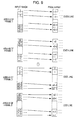
- FIGS. 7A and 7B are diagrams illustrating driving waveforms of scanning lines when a driving method according to the first embodiment is performed;
- FIGS. 8A and 8B are diagrams describing a driving method according to a second embodiment of the present invention.
- FIG. 9 is a diagram describing a driving method according to the second embodiment.
- FIGS. 10A and 10B are diagrams illustrating a pattern of light and dark states of lines when area divisional driving and simultaneous driving of two lines are performed in combination;
- FIG. 11 is a diagram illustrating an internal configuration of a display apparatus according to the second embodiment.
- FIG. 12 is a diagram illustrating an internal configuration of a video signal processing section included in a display apparatus according to the second embodiment
- FIGS. 13A and 13B are diagrams illustrating driving waveforms of scanning lines when a driving method according to the second embodiment is performed (in which combinations of two simultaneously driven lines with which no redundant line is generated are driven);
- FIGS. 14A and 14B are diagrams illustrating driving waveforms of scanning lines when a driving method according to the second embodiment is performed (in which combinations of two simultaneously driven lines with which a redundant line is generated are driven);
- FIG. 15 is a diagram describing a driving method according to a third embodiment of the present invention of simply associating one input pixel with two display pixels;
- FIG. 16 is a diagram describing a driving method according to the third embodiment of associating an average of signal values of two adjacent input pixels with two display pixels;
- FIGS. 17A to 17D are diagrams describing an effect obtained from a driving method according to the third embodiment.
- FIG. 18 is a diagram illustrating an internal configuration of a video signal processing section included in a display apparatus according to the third embodiment
- FIG. 19 is a diagram describing normal bipolar driving
- FIGS. 20A to 20D are diagrams describing a problem that occurs when a bipolar driving method and switching between an EVEN frame and an ODD frame are performed;
- FIG. 21 is a diagram illustrating the relationship between each frame and a driving polarity when a bipolar driving method and the switching between an EVEN frame and an ODD frame in each frame period are performed;
- FIG. 22 is a diagram describing a driving method according to a fourth embodiment of the present invention.
- FIG. 23 is a diagram illustrating an internal configuration of a video signal processing section included in a display apparatus according to the fourth embodiment.
- FIG. 24 is a diagram illustrating the relationship among each frame, the waveform of an E/O switching signal, and the waveform of a polarity instruction signal when a driving method according to the fourth embodiment is performed;
- FIG. 25 is a diagram describing a driving method according to a fifth embodiment of the present invention.
- FIG. 26 is a diagram describing an internal configuration of a display apparatus according to the fifth embodiment.
- FIG. 27 is a diagram illustrating the relationship among each frame, the waveform of an E/O switching signal, and the waveform of a polarity instruction signal when a driving method according to the fifth embodiment is performed;
- FIG. 28 is a diagram illustrating an internal configuration of a display apparatus according to a sixth embodiment of the present invention.
- FIG. 29 is a diagram illustrating an internal configuration of a video signal processing section included in a display apparatus according to the sixth embodiment.
- FIG. 30 is a diagram illustrating an internal configuration of an image evaluation circuit included in a display apparatus according to the sixth embodiment.
- FIG. 31 is a diagram describing a configuration of a modification of a display apparatus according to an embodiment of the present invention which divisionally driving signal lines in units of combinations of a predetermined number of signal lines;
- FIG. 32 is a diagram describing a driving method in the related art of simultaneously driving a plurality of scanning lines
- FIG. 33 is a diagram illustrating a pattern of light and dark states of lines.
- FIG. 34 is a diagram describing an exemplary principle of the occurrence of a crosstalk between lines at the time of simultaneous driving of two lines.
- FIG. 1 is a diagram illustrating the configuration of a display panel included in a display apparatus according to an embodiment of the present invention.
- a display apparatus according to an embodiment of the present invention having an entire configuration to be described later is an active matrix liquid crystal display apparatus.
- FIG. 1 illustrates the configuration of a liquid crystal display panel included in a display apparatus according to an embodiment of the present invention that is such a liquid crystal display apparatus.
- a display panel includes a pixel array 1 , a gate driver 2 , and a source driver 3 .
- the pixel array 1 includes an element substrate on which a plurality of scanning lines and a plurality of signal lines orthogonal to the scanning lines are formed and a combination of a capacitor C functioning as a voltage storage capacitor and a switching element Q is formed at each of intersections of the scanning lines and the signal lines.
- a counter substrate is disposed at a position opposite to the element substrate and the space between the element substrate and the counter substrate is filled with liquid crystal.
- a combination of the capacitor C and the switching element Q that is disposed at each of the intersections of the scanning lines and the signal lines is a single pixel P in the pixel array 1 .
- a field-effect transistor FET
- the gate of the switching element Q is connected to a scanning line
- the source of the switching element Q is connected to a signal line
- the drain of the switching element Q is connected to the capacitor C.
- the gate driver 2 is disposed to drive the scanning lines formed in the pixel array 1
- the source driver 3 is disposed to drive the signal lines.
- the gate driver 2 When the gate driver 2 applies a voltage to a certain scanning line ⁇ (brings the scanning line ⁇ into an ON state), the switching elements Q connected to the scanning line ⁇ are turned on. This causes a state in which an electric charge can be stored in the capacitor C included in each of the pixels P arranged in the scanning line ⁇ (active state). That is, when the source driver 3 drives each signal line on the basis of a value corresponding to an input image signal after the gate driver 2 has brought the scanning line ⁇ into the active state, it is possible to write a desired signal value into each of the pixels P arranged in the scanning line ⁇ .
- each scanning line is also referred to as a gate line as illustrated in FIG. 1 .
- each scanning line is also referred to as a horizontal line.
- Scanning lines in the pixel array 1 are numbered starting from zero for the uppermost scanning line.
- signal lines are also referred to as source lines or vertical lines, and are numbered from zero for the leftmost signal line.
- the number of pixels P formed in the pixel array 1 is 1920 pixels in the horizontal direction ⁇ 1080 pixels in the vertical direction. That is, there are vertical lines 0 to 1919 and horizontal lines 0 to 1079 .
- FIGS. 2A and 2B are diagrams describing a driving method according to the first embodiment.
- FIG. 2A illustrates the gate lines (horizontal lines) 0 to 7 extracted from the gate lines formed in the pixel array 1 illustrated in FIG. 1 .
- FIG. 2B illustrates the gate lines 0 to 8 extracted from the gate lines formed in the pixel array 1 illustrated in FIG. 1 .
- a method of driving a plurality of lines at the same time in a period of one horizontal line which is similar to the method in the related art described previously with reference to FIG. 32 , is performed.
- the combinations of a plurality of simultaneously driven lines are changed as illustrated in FIGS. 2A and 2B .
- a frame period means a frame period of an input image signal, that is, a frame period based on a synchronization signal obtained from an input video signal.
- a combination of lines 0 and 1 , a combination of lines 2 and 3 , a combination of lines 4 and 5 , and a combination of lines 6 and 7 are sequentially driven as combinations of simultaneously driven lines.
- the combinations of simultaneously driven lines are changed to a combination of the lines 1 and 2 , a combination of the lines 3 and 4 , a combination of the lines 5 and 6 , and a combination of the line 7 and a line 8 , and are sequentially driven.
- a redundant line incapable of being driven simultaneously with another line may be generated in accordance with the set number of horizontal lines included in the pixel array 1 and the number of simultaneously driven lines.
- the number of horizontal lines included in the pixel array 1 is an even number and the number of simultaneously driven lines is two
- lines incapable of being driven simultaneously with another line are generated when driving is performed as illustrated in FIG. 2B .
- Each of these redundant lines is independently driven.
- the number of simultaneously driven lines when the number of simultaneously driven lines is set to three or more and the number of redundant lines is two or more, these redundant lines may be simultaneously driven.
- a redundant line when the number of horizontal lines is an odd number, a redundant line may be generated with any combinations of simultaneously driven lines. That is, all combinations of simultaneously driven lines generate a redundant line. In this state, the combinations of simultaneously driven lines with which a redundant line is generated are changed.
- an image to be displayed is processed in addition to the above-described change in the combination of simultaneously driven lines.
- FIGS. 3A and 3B are diagrams describing a concrete method of processing an image to be displayed.
- FIG. 3A illustrates an image display method performed at the time of normal driving in which a plurality of lines are not simultaneously driven.
- FIG. 3B illustrates a driving method according to the first embodiment.
- EVEN even-numbered lines
- a signal value of each of the extracted EVEN lines is input into a corresponding combination of two simultaneously driven lines in an image to be displayed. More specifically, an image signal of an extracted line 0 in the frame 1 is input into a combination of lines 0 and 1 in an image to be displayed, and an image signal of an extracted line 2 in the frame 1 is input into a combination of lines 2 and 3 in the image to be displayed.
- driving of simultaneously driven lines and writing of a signal value into these lines are performed in synchronization with each other so that the vertical order of lines in an input image is consistent with the vertical order of lines in an image to be displayed.
- a second frame image In a second frame image (frame 2 ), only odd-numbered (ODD) lines are basically extracted and are then output.
- a signal value of each of the extracted ODD lines is input into a corresponding combination of two simultaneously driven lines.
- driving of each line (scanning line) and writing of a signal value into the line are similarly performed in synchronization with each other so that the vertical order of lines in an input image is consistent with the vertical order of lines in an image to be displayed.
- the extraction and output of EVEN lines and the extraction and output of ODD lines are alternately performed.
- the line 0 illustrated in the drawing and a line 1079 become redundant lines.
- a signal value of the last line 1079 can be input into only the redundant scanning line 1079 . Accordingly, a signal value of an ODD line having the largest line number in an input frame image is written into the last remaining redundant line (a scanning line having the largest line number) at the time of driving the last remaining redundant line as described previously.
- combinations of simultaneously driven lines are changed in each frame period and writing (display) of only EVEN lines included in an input frame image and writing (display) of only ODD lines included in the input frame image are alternately performed in each frame period.
- writing (display) of only EVEN lines included in an input frame image and writing (display) of only ODD lines included in the input frame image are alternately performed in each frame period.
- the signal value of the line 0 is also output and is then written into the redundant line 0 .
- Another redundant line 1079 is independently scanned on the basis of a signal value of the line 1079 .
- FIG. 4A illustrates a frame rate obtained when the normal driving method illustrated in FIG. 3A is performed.
- FIG. 4B illustrates a frame rate obtained when the above-described driving method according to the first embodiment is performed.
- a frame rate obtained when the normal driving method is performed is 60 Hz (60 fps).
- a driving method according to the first embodiment it is possible to reduce a time length necessary for scanning of one frame image to half that at the time of the normal driving by driving two lines at the same time and alternately performing the extraction and output of EVEN lines and the extraction and output of ODD lines in each frame period as illustrated in FIG. 3B .
- FIG. 5 is a diagram illustrating the internal configuration of a display apparatus according to the first embodiment.
- a display apparatus according to the first embodiment includes the pixel array 1 , the gate driver 2 , and the source driver 3 , which are illustrated in FIG. 1 , a video signal processing section 4 , and a control section 5 .
- the video signal processing section 4 receives an input video signal.
- a frame rate can be increased from 60 fps obtained with related art to 120 fps. Accordingly, an input video signal of 120 fps is supplied to the video signal processing section 4 .
- the video signal processing section 4 performs synchronization separation processing upon the input video signal and extraction processing of EVEN lines or ODD lines upon the input video signal on the basis of an EVEN/ODD switching signal (hereinafter referred to as an E/O switching signal) supplied from the control section 5 .
- FIG. 6 is a diagram illustrating the internal configuration of the video signal processing section 4 .
- the video signal processing section 4 includes a line thinning-out processing unit 6 , a line buffer 7 , and a synchronization separation circuit 8 .
- the input video signal illustrated in FIG. 5 is supplied to the line thinning-out processing unit 6 and the synchronization separation circuit 8 as illustrated in FIG. 6 .
- the synchronization separation circuit 8 separates a vertical synchronization signal and a horizontal synchronization signal from the input video signal. These synchronization signals separated by the synchronization separation circuit 8 are supplied to the control section 5 illustrated in FIG. 1 .
- the line thinning-out processing unit 6 extracts image signals of only even-numbered horizontal lines or extracts image signals of odd-numbered horizontal lines and an image signal of a line 0 from a frame image signal obtained from the input video signal on the basis of the E/O switching signal supplied from the control section 5 and outputs the extracted image signals. More specifically, when the line thinning-out processing unit 6 is instructed to output image signals of EVEN lines by the E/O switching signal, it extracts image signals of lines 0 , 2 , 4 , . . . , and 1078 from the frame image signal obtained from the input video signal and sequentially outputs the extracted image signals using the line buffer 7 .
- the line thinning-out processing unit 6 When the line thinning-out processing unit 6 is instructed to output image signals of ODD lines by the E/O switching signal, it extracts image signals of lines 1 , 3 , 5 , . . . , and 1079 and an image signal of a line 0 from the frame image signal obtained from the input video signal and sequentially outputs the extracted image signals using the line buffer 7 .
- the control section 5 functions as a scanning control unit or an even/odd-numbered line output switching control unit on the basis of the synchronization signals supplied from the video signal processing section 4 (the synchronization separation circuit 8 ).
- the function of the scanning control unit is a function of controlling the gate driver 2 so that two lines are simultaneously driven and combinations of simultaneously driven lines are changed every frame as described previously with reference to FIG. 2 .
- the function of the even/odd-numbered line output switching control unit is a function of supplying to the line thinning-out processing unit 6 an E/O switching signal used for an instruction for alternately performing the extraction and output of EVEN lines and the extraction and output of ODD lines (and the line 0 ) as described previously with reference to FIG. 3B .
- the control section 5 supplies a timing signal used for an instruction for driving the scanning lines and the signal lines included in the pixel array 1 at a predetermined time based on the synchronization signal supplied from the video signal processing section 4 .
- the control section 5 alternately transmits to the gate driver 2 in each frame period information used to instruct the gate driver 2 to sequentially drive a combination of lines 0 and 1 , a combination of lines 2 and 3 , a combination of lines 4 and 5 , a combination of lines 6 and 7 , etc. and information used to instruct the gate driver 2 to independently drive the line 0 and a line 1079 and sequentially drive a combination of the lines 1 and 2 , a combination of the lines 3 and 4 , a combination of the lines 5 and 6 , etc.
- control section 5 alternately transmits to the gate driver 2 in each frame period based on the synchronization signal information used to instruct the gate driver 2 to sequentially drive combinations of two simultaneously driven lines with which no redundant line is generated and information used to instruct the gate driver 2 to sequentially drive combinations of two simultaneously driven lines with which a redundant line is generated and independently drive the redundant lines.
- each scanning line is driven so that combinations of two simultaneously driven lines that are adjacent to each other in the vertical direction are sequentially driven and the combinations of two simultaneously driven lines are changed in each frame period.
- FIGS. 7A and 7B illustrate the waveforms of waves for driving scanning lines (horizontal lines) that are output by the gate driver 2 on the basis of the above-described information transmitted from the control section 5 in each frame period.
- FIG. 7A illustrates waveforms of driving waves that are used to sequentially drive the combination of the simultaneously driven lines 0 and 1 , the combination of the simultaneously driven lines 2 and 3 , the combination of the simultaneously driven lines 4 and 5 , the combination of the simultaneously driven lines 6 and 7 , etc.
- FIG. 7B illustrates waveforms of driving waves that are used to independently drive the line 0 and then sequentially drive the combination of the simultaneously driven lines 1 and 2 , the combination of the simultaneously driven lines 3 and 4 , the combination of the simultaneously driven lines 5 and 6 , etc.
- control section 5 generates and outputs an E/O switching signal used to switch between EVEN lines and ODD lines in each frame period.
- image signals of EVEN lines are output for display when combinations of a plurality of simultaneously driven lines with which no redundant line is generated are sequentially driven, and an image signal of the line 0 and image signals of ODD lines are output for display when combinations of a plurality of simultaneously driven lines with which a redundant line is generated are sequentially driven.
- image signals of ODD lines may be output for display when combinations of a plurality of simultaneously driven lines with which no redundant line is generated are sequentially driven
- image signals of EVEN lines may be output for display when combinations of a plurality of simultaneously driven lines with which a redundant line is generated are sequentially driven.
- a redundant line is generated at the time of display of EVEN lines.
- the signal value of an EVEN line (the line 0 ) having the smallest line number is written into a scanning line having a line number 0 at the time of driving the scanning line.
- the image of a line 1 in an input image is displayed at a combination of the scanning lines 0 and 1 and the image of a line 3 in the input image is displayed at a combination of scanning lines 2 and 3 .
- the image of the line 0 in the input image is displayed at the scanning line 0 and the image of the line 2 in the input image is displayed at a combination of the scanning lines 1 and 2 .
- the reduction in a time length necessary for scanning of one frame is achieved by dividing the pixel array 1 into a plurality of areas and independently (simultaneously) performing driving of scanning lines in these areas. Furthermore, a frame rate is increased to at least four times a frame rate at the time of normal driving by performing the scanning described in the first embodiment in each of these areas.
- FIGS. 8A , 8 B, and 9 are diagrams describing a driving method according to the second embodiment.
- the pixel array 1 is equally divided into two areas, an upper area A and a lower area B, in a vertical direction.
- scanning directions in the areas differ from each other.
- scanning directions scanning sequences
- This leads to improvement in moving image quality see Japanese Unexamined Patent Application Publication No. 2007-212571.
- FIG. 9 illustrates a concrete driving method according to the second embodiment in which the combinations of simultaneously driven lines are changed in each frame period and EVEN lines and ODD lines are alternately set as lines to be displayed.
- FIG. 9 illustrates a display state transition in display periods of two frames, frames 1 and 2 . First, in the frame 1 , only image signals of EVEN lines in the areas A and B are extracted and output as illustrated in FIG. 9 . Referring to FIG.
- a combination of lines 0 and 1 , a combination of lines 2 and 3 , . . . , and a combination of lines n/2 ⁇ 2 and n/2 ⁇ 1 are set as combinations of simultaneously driven lines in the area A, and a combination of lines n/2 and n/2+1, a combination of lines n/2+2 and n/2+3, . . . , a combination of lines n ⁇ 4 and n ⁇ 3, and a combination of lines n ⁇ 2 and n ⁇ 1 are sets as combinations of simultaneously driven lines in the area B. Both the combinations of simultaneously driven lines in the area A and the combinations of simultaneously driven lines in the area B generate no redundant line.
- each combination of simultaneously driven lines and a signal value (line included in an input image) written into the combination of simultaneously driven lines at the time of driving the combination of simultaneously driven lines are associated with each other so that the vertical order of lines in an input image is consistent with the vertical order of lines in an image to be displayed.
- a scanning start position is on the side of the boundary between the areas A and B. Accordingly, lines are scanned in descending order of line number in the area A, and lines are scanned in ascending order of line number in the area B.
- image signals of a line 0 and ODD lines in the area A are extracted and output and image signals of a line n/2 and ODD lines in the area B are extracted and output.
- a combination of lines 1 and 2 , . . . , and a combination of lines n/2 ⁇ 3 and n/2 ⁇ 2 are set as combinations of simultaneously driven lines in the area A, and a combination of lines n/2+1 and n/2+2, . . . , and a combination of lines n ⁇ 3 and n ⁇ 2 are set as combinations of simultaneously driven lines in the area B.
- the combinations of simultaneously driven lines in the area A generate the line 0 and a line n/2 ⁇ 1 as redundant lines
- the combinations of simultaneously driven lines in the area B generate lines n/2 and n ⁇ 1 as redundant lines.
- a signal value of a line 0 is written into the line 0
- a signal value of a line n/2 is written into the line n/2.
- a scanning start position in each of the areas is on the side of the boundary between the areas.
- a scanning sequence in the area B is the same as that in the first embodiment. Accordingly, a driving method according to the first embodiment can be performed in the area B.
- a scanning direction in the area A is opposite to that in the first embodiment, the relationship between each line and an image to be displayed in the line is the same as that in the first embodiment (that is, it is ensured that a display vertical positional relationship among lines in an input image is consistent with a display vertical positional relationship among lines in an image to be displayed).
- the pixel array 1 is divided into the areas A and B.
- two adjacent lines are simultaneously driven and combinations of simultaneously driven lines are changed in each frame period.
- the combinations of simultaneously driven lines are changed in each frame period and EVEN lines and the ODD lines are alternately output as lines to be displayed as described previously, it is possible to achieve a scanning method, for example, the interlacing display method, like in the first embodiment. This leads to the improvement in vertical resolution sensitivity.
- the succession of dark states of lines and the succession of light states of lines are generated at the boundary between the areas and allow a viewer to view a dark line and a bright line at the boundary between the areas as illustrated in FIGS. 10A and 10B .
- the number of horizontal lines is an even number
- the number of simultaneously driven lines is two, and combinations of simultaneously driven lines generate no redundant line, light and dark patterns generated in the areas A and B are as illustrated in FIG. 10A .
- two lines at the boundary between the areas A and B become dark and a dark line is therefore viewed at the boundary between the areas A and B.
- the number of horizontal lines is an even number
- the number of simultaneously driven lines is two, and combinations of simultaneously driven lines generate a redundant line, light and dark patterns generated in the areas A and B are as illustrated in FIG. 10B .
- two lines at the boundary between the areas A and B become light and a bright line is therefore viewed at the boundary between the areas A and B.
- FIG. 11 is a diagram illustrating the internal configuration of a display apparatus according to the second embodiment for achieving the above-described driving method according to the second embodiment.
- FIG. 11 describing the configuration of a display apparatus (including the internal configuration of a video signal processing section), the same reference numerals are used to identify components that have already been described so as to prevent repeated explanation.
- This display apparatus includes an area A gate driver 2 A for driving each scanning line (each of the lines 0 to n/2 ⁇ 1 in the example illustrated in FIG. 9 ) in the area A and an area B gate driver 2 B for driving each scanning line (each of the lines n/2 to n ⁇ 1 in the example illustrated in FIG. 9 ) in the area B.
- the display apparatus includes an area A source driver 3 A and an area B source driver 3 B so as to independently performing scanning in the areas A and B.
- a frame rate it is possible to increase a frame rate to four times a frame rate (60 fps) at the time of normal driving. Accordingly, a video signal of 240 fps is input into this display apparatus as illustrated in FIG. 11 . Furthermore, in the second embodiment, as described previously, since scanning is performed starting from the line n/2 ⁇ 1 in the area A, the area A gate driver 2 A is configured to perform scanning starting from the line n/2 ⁇ 1.
- the display apparatus illustrated in FIG. 11 includes a video signal processing section 11 instead of the video signal processing section 4 included in the display apparatus illustrated in FIG. 5 .
- FIG. 12 is a diagram illustrating the internal configuration of the video signal processing section 11 .
- the video signal processing section 11 includes an area dividing unit 12 , a combination of a line thinning-out processing unit 6 A and a line buffer 7 A, a combination of a line thinning-out processing unit 6 B and a line buffer 7 B, and the synchronization separation circuit 8 .
- the area dividing unit 12 divides a frame image signal obtained from the input video signal into image signals for areas set in the pixel array 1 and outputs the image signals. More specifically, in this case, the area dividing unit 12 divides the frame image signal into image signals of lines 0 to n/2 ⁇ 1 for the area A and image signals of lines n/2 to n ⁇ 1 for the area B and outputs these image signals.
- the image signals for the area A are supplied to the line thinning-out processing unit 6 A, and the image signals for the area B are supplied to the line thinning-out processing unit 6 B.
- the line thinning-out processing units 6 A and 6 B perform thinning-out processing upon the image signals and output results of the thinning-out processing using the line buffers 7 A and 7 B, respectively.
- lines are scanned in ascending order of line number. Accordingly, the line thinning-out processing unit 6 B performs the same processing performed by the line thinning-out processing unit 6 illustrated in FIG.
- the line thinning-out processing unit 6 A is configured to extract lines and output the extracted lines in descending order of line number.
- the line thinning-out processing unit 6 A is instructed to extract ODD lines by the E/O switching signal, it outputs an image signal of the line 0 in addition to image signals of ODD lines.
- a control section 10 supplies a timing instruction based on a synchronization signal to the area A gate driver 2 A, the area B gate driver 2 B, the area A source driver 3 A, and the area B source driver 3 B and provides an instruction for switching between EVEN lines and ODD lines to be extracted and output using an E/O switching signal. More specifically, the control section 10 supplies timing signals to the area A gate driver 2 A, the area B gate driver 2 B, the area A source driver 3 A, and the area B source driver 3 B so that scanning line driving and signal line driving are performed in the areas A and B at a predetermined time based on the synchronization signal supplied from the video signal processing section 11 (the synchronization separation circuit 8 ).
- the control section 10 alternately transmits to each of the area A gate driver 2 A and the area B gate driver 2 B in each frame period information used for an instruction for sequentially driving combinations of two simultaneously driven lines with which no redundant line is generated and information used for an instruction for sequentially driving combinations of two simultaneously driven lines with which a redundant line is generated.
- each scanning line is driven so that combinations of two simultaneously driven lines that are adjacent to each other in the vertical direction are sequentially driven and the combinations of two simultaneously driven lines are changed in each frame period.
- control section 10 generates and outputs an E/O switching signal used for an instruction for switching between EVEN lines and ODD lines in each frame period like in the first embodiment.
- the generated E/O switching signal is supplied to the line thinning-out processing unit 6 A and the line thinning-out processing unit 6 B as illustrated in FIG. 12 .
- FIGS. 13A and 14A are diagrams illustrating the waveforms of waves for driving scanning lines (horizontal lines) that are output by the area A gate driver 2 A under the above-described control of the control section 10 .
- FIGS. 13B and 14B are diagrams illustrating the waveforms of waves for driving scanning lines (horizontal lines) that are output by the area B gate driver 2 B under the above-described control of the control section 10 .
- FIGS. 13A and 14A illustrate eight lines (lines 0 to 7 ) included in the area A
- FIGS. 13B and 14B illustrate eight lines (lines 8 to 15 ) included in the area B.
- FIGS. 13A and 13B illustrate the waveforms of waves for driving combinations of two lines with which no redundant line is generated.
- FIGS. 14A and 14B illustrate the waveforms of waves for driving combinations of two lines with which a redundant line is generated.
- FIG. 15 illustrates six input pixels (pixels 0 to 5) in the vertical direction and twelve display pixels (pixels 0 to 11) in the vertical direction.
- the change in an image to be displayed is performed in each frame period in addition to the simultaneous driving of two lines and the change in the combinations of simultaneously driven lines in each frame period. More specifically, as illustrated in FIG. 15 , when combinations of two simultaneously driven lines with which no redundant line is generated are driven, image display is performed so that input pixels are individually associated with combinations of two display pixels that are adjacent to each other in the vertical direction. On the other hand, as illustrated in FIG. 16 , when the combinations of two simultaneously driven lines with which a redundant line is generated are driven, an input pixel having the smallest pixel number and an input pixel having the largest pixel number are associated with display pixels 0 and 11, respectively, that are redundant display pixels. Furthermore, the input pixels are grouped into combinations of two adjacent input pixels, and an average of two adjacent input pixels included in each of the combinations of two adjacent input pixels is calculated and is associated with a corresponding combination of two simultaneously driven display pixels.
- FIGS. 15 and 16 illustrate the relationship between one of input pixels included in each horizontal line and corresponding one of display pixels included in a corresponding horizontal line.
- the illustrated relationship is established between each of input pixels included in each horizontal line and corresponding one of display pixels included in a corresponding horizontal line. More specifically, when combinations of simultaneously driven lines with which no redundant line is generated are driven as illustrated in FIG. 15 , each signal line is driven on the basis of an image signal of each horizontal line included in a frame image signal obtained from an input video signal. In the case of combinations of simultaneously driven lines with which a redundant line is generated illustrated in FIG.
- each signal line when a line (scanning line) having the smallest line number is driven, each signal line is driven on the basis of an image signal of a horizontal line having the smallest line number included in a frame image signal obtained from an input video signal.
- a line (scanning line) having the largest line number is driven, each signal line is driven on the basis of an image signal of a horizontal line having the largest line number included in the frame image signal obtained from the input video signal.
- FIGS. 17A to 17D Effects obtained by performing the above-described driving method according to the third embodiment will be described with reference to FIGS. 17A to 17D .
- horizontal axes represent the number of display pixels in the vertical direction (eight pixels from a pixel 0 to a pixel 7 in this example), white circles represent an input brightness value, and vertical bars represent a display brightness value.
- FIG. 17B illustrates the brightness level of each pixel in a case where the driving method illustrated in FIG. 16 is performed (combinations of simultaneously driven lines generate a redundant line and the average signal value of adjacent pixels is used to display an image in simultaneously driven lines included in each of the combinations of simultaneously driven lines).
- FIG. 17C illustrates a state in which the display image illustrated in FIG. 17A and the display image illustrated in FIG. 17B are superimposed.
- a viewer perceives brightness levels illustrated in FIG. 17C .
- FIG. 17D illustrates black circles on the superimposed image illustrated in FIG. 17C so as to prominently display brightness levels perceived by a viewer. It is apparent from FIG. 17D that the black circles are displaced by 1 ⁇ 4 pixel and 3 ⁇ 4 pixel from the positions of input pixels (that is, the position of pixels 0+1, the position of pixels 2+3, etc.). This is equivalent to that an input image is resampled at positions that are displaced by 1 ⁇ 4 pixel and 3 ⁇ 4 pixel from normal pixel positions in the vertical direction. Accordingly, it is possible to improve a resolution sensitivity in the vertical direction.
- values indicated by the black circles illustrated in FIG. 17D are brightness values obtained from (3A+B)/4 and (A+3B)/4 where A and B individually represent the values of adjacent input pixels.
- the number of pixels in the vertical direction in the pixel array 1 is twice the number of pixels in the vertical direction in an input image, it is possible to prevent the generation of stripes formed by a light and dark pattern by simultaneously driving two lines and changing combinations of simultaneously driven lines like in the above-described embodiments. This leads to improvement in image quality.
- by alternately performing the simple output of an image signal of each horizontal line and the output of an average signal value of adjacent pixels in each frame period it is possible to prevent a resolution sensitivity in the vertical direction from being reduced by half when two lines are simply driven at the same time. This leads to improvement in image quality.
- FIG. 18 illustrates the internal configuration of the video signal processing section 15 included in a display apparatus according to the third embodiment. The illustration and description of the entire internal configuration of the display apparatus will be omitted.
- a frame rate can be set to twice a frame rate (60 fps) at the time of normal driving, a video signal of 120 fps is input into the video signal processing section 15 as illustrated in FIG. 18 .
- the video signal processing section 15 includes the synchronization separation circuit 8 , an average calculation circuit 16 , an output control unit 17 , and the line buffer 7 .
- the input video signal is supplied to the synchronization separation circuit 8 , the average calculation circuit 16 , and the output control unit 17 .
- the average calculation circuit 16 the output control unit 17 , and the line buffer 7 function as a normal output/average output switching processing unit for switching between normal output processing for sequentially outputting image signals of horizontal lines included in a frame image obtained from the input video signal and average output processing for grouping the horizontal lines included in the frame image into combinations of two adjacent horizontal lines, calculating an average of image signals of two adjacent horizontal lines included in each of the combinations of two adjacent horizontal lines on a pixel-by-pixel basis, and outputting a result of the calculation.
- the average calculation circuit 16 groups the horizontal lines included in the frame image obtained from the input video signal into combinations of two adjacent horizontal lines, calculates an average of image signals of two adjacent horizontal lines included in each of the combinations of two adjacent horizontal lines on a pixel-by-pixel basis, and outputs a result of the calculation to the output control unit 17 .
- the output control unit 17 performs output control of an image signal supplied to the source driver 3 (not illustrated) by switching, on the basis of an E/O switching signal transmitted from the control section 5 (not illustrated), between processing for receiving from the average calculation circuit 16 a pixel-by-pixel average of signal values of adjacent lines included in each combination of adjacent lines and line-sequentially outputting these averages using the line buffer 7 and processing for line-sequentially outputting image signals of horizontal lines included in a frame image signal obtained from an input video signal using the line buffer 7 . More specifically, when the E/O switching signal indicates an EVEN instruction, the output control unit 17 performs the processing for line-sequentially outputting image signals of horizontal lines included in a frame image signal obtained from an input video signal.
- the output control unit 17 performs the processing for receiving from the average calculation circuit 16 a pixel-by-pixel average of signal values of adjacent lines included in each combination of adjacent lines and line-sequentially outputting these averages.
- the image signals of horizontal lines included in the frame image signal are sequentially output to the source driver 3 . That is, the driving method described previously with reference to FIG. 15 is achieved.
- a bipolar driving method is known as a driving method used to keep a DC balance of a writing voltage and is employed in, for example, Liquid Crystal On Silicon (LCOS) panels and Silicon X-tal Reflective Display (SXRD: the registered trademark of Sony Corporation) panels.
- LCOS Liquid Crystal On Silicon
- SXRD Silicon X-tal Reflective Display
- FIG. 19 is a conceptual diagram of normal bipolar driving (bipolar driving in the related art).
- the polarity of a writing voltage is reversed at a rate of 120 Hz and the same frame is output two times at the time of bipolar driving as illustrated in FIG. 19 so as to keep the DC balance of a writing voltage.
- signal values of the frame 1 are written in a positive polarity in a first half of a period of 60 Hz (approximately 16.6 msec) of one input frame, and signal values of the frame 1 are written in a negative polarity in a latter half of the period.
- writing of signal values of the same frame image is performed in both the positive polarity and the negative polarity.
- the positive polarity of signal values and the negative polarity of signal values cancel each other and a DC balance can be maintained.
- FIGS. 20B and 20C illustrate two types of display images illustrated in FIGS. 20B and 20C. More specifically, FIG. 20B illustrates a display image generated when combinations of two simultaneously driven lines with which no redundant line is generated are used and each signal line is driven on the basis of image signals of extracted EVEN lines.
- FIG. 20C illustrates a display image generated when combinations of two simultaneously driven lines with which a redundant line is generated are used and each signal line is driven on the basis of image signals of extracted ODD lines (in this case, a signal value of a line 0 included in an input image is written into a redundant line having the smallest line number).
- the numbers of pixels in an input image and a display image are 8 ⁇ 8.
- a large number of pixels for example, 1920 pixels ⁇ 1080 pixels, are included in an input image and a display image.
- a frame illustrated in FIG. 20B in which each signal line is driven on the basis of image signals of extracted EVEN lines is referred to as an EVEN frame
- a frame illustrated in FIG. 20C in which each signal line is driven on the basis of image signals of extracted ODD lines is referred to as an ODD frame.
- FIG. 21 illustrates the transition of display image states of four frames, a frame 1 to a frame 4 , along with a driving polarity for each frame when an EVEN frame and an ODD frame are alternately output for display in each frame period.
- FIG. 21 illustrates the change in a display image when the same input image illustrated in FIG. 20A is continuously obtained in four frames, that is, when the same still image is input in a four-frame period.
- mismatching between a signal value of each pixel obtained in a driving period in which the positive polarity is used and a signal value of a corresponding pixel obtained in a driving period in which the negative polarity is used may similarly occur, and burn-in may similarly occur.
- FIG. 22 illustrates the change in a display image in a four-frame period in which the same still image is input.
- an EVEN frame and an ODD frame are not alternately used in each frame period.
- FIG. 23 is a diagram illustrating the internal configuration of a display apparatus according to the fourth embodiment for achieving the above-described driving method according to the fourth embodiment.
- a display apparatus according to the fourth embodiment differs from the display apparatus according to the first embodiment illustrated in FIG. 5 in that a control section 20 is used instead of the control section 5 .
- the source driver 3 differs from the source driver 3 according to the first embodiment in that it is configured to drive each signal line in a polarity instructed by a polarity instruction signal transmitted from the control section 20 on the basis of an image output from the video signal processing section 4 .
- the control section 20 included in a display apparatus causes the gate driver 2 to perform driving of each scanning line (including simultaneous driving of two lines and the change in combinations of simultaneously driven lines in each frame period) at a time based on a synchronization signal supplied from the video signal processing section 4 (the synchronization separation circuit 8 ) and controls a time at which the source driver 3 drives each signal line.
- an E/O switching signal used for an EVEN/ODD switching instruction is similarly supplied to the video signal processing section 4 (the line thinning-out processing unit 6 ).
- the E/O switching signal generated by the control section 20 is not a signal used for an instruction for switching between an EVEN frame and an ODD frame in each frame period but a signal used for an instruction for performing switching between an EVEN frame and an ODD frame between a first frame and a second frame included in a combination of four continuous frames and between a third frame and a fourth frame included in the combination of four continuous frames.
- the control section 20 generates on the basis of a synchronization signal supplied from the video signal processing section 4 a polarity instruction signal used for an instruction for alternately setting the positive polarity and the negative polarity in each frame period and supplies the polarity instruction signal to the source driver 3 .
- FIG. 24 illustrates the relationship among a time at which each frame is displayed, the waveform of an E/O switching signal, and the waveform of a polarity instruction signal when driving is performed under the control of the control section 20 .
- FIG. 24 illustrates the relationship among a time at which each frame is displayed, the waveform of an E/O switching signal, and the waveform of a polarity instruction signal in a period of eight frames, a frame 1 to a frame 8 . As illustrated in FIG.
- an E/O switching signal used for an EVEN instruction is generated in display periods of the frames 1 , 4 , 5 , and 8
- an E/O switching signal used for an ODD instruction is generated in display periods of the frames 2 , 3 , 6 , and 7 .
- a polarity instruction signal is generated so that the positive polarity and the negative polarity are alternately set in each frame period starting from the positive polarity in the display period of the frame 1 .
- the fourth embodiment it is possible to increase a frame rate and maintain a DC balance when input frame images among which relatively high correlations are obtained are displayed.
- frame images among which relatively low correlations are obtained for example, a moving image with relatively fast motion
- the bipolar driving method illustrated in FIG. 19 is effective to maintain a DC balance in input images having any characteristic.
- a method will be proposed capable of increasing a frame rate and maintaining a perfect DC balance obtained when normal bipolar driving is performed.
- FIG. 25 is a diagram describing a driving method according to the fifth embodiment and illustrates the relationship between a display image and a driving polarity.
- the same frame is output two times. At the time of first output of the frame, driving in the positive polarity is performed. At the time of second output of the frame, driving in the negative polarity is performed.
- a driving method according to the fifth embodiment differs from a normal bipolar driving method in that an EVEN frame or an ODD frame is used at the time of displaying each frame to reduce a scanning time. That is, it is possible to double a frame rate from that in the related art by using an EVEN frame or an ODD frame.
- the switching between an EVEN frame and an ODD frame is not performed in a period in which the same frame is displayed (a scanning period of one frame ⁇ 2), and is performed when a display frame is changed. That is, from the viewpoint of scanning, the switching between an EVEN frame and an ODD frame is performed each time the scanning of the same frame is performed two times.
- the first scanning and second scanning of the same frame image are individually performed in the positive driving polarity and the negative driving polarity and the switching between an EVEN frame and an ODD frame is performed each time the first scanning and second scanning of the same frame image are performed.
- a driving method according to the fifth embodiment like in a case where a normal bipolar driving method is employed, it is possible to perform driving (writing) of the same image in both the positive polarity and the negative polarity and maintain a perfect DC balance in any of input images including a moving image with fast motion.
- the fifth embodiment since a time length necessary for scanning of one frame is reduced by half by applying the display and output of an EVEN frame/an ODD frame, it is possible to double a frame rate from that obtained when a normal bipolar driving method is performed. This leads to the improvement in moving image quality.
- a driving method according to the fifth embodiment since an EVEN frame and an ODD frame are alternately used each time a frame image is changed (that is, between the frame 1 and the frame 2 ), it is possible to achieve a scanning method, for example, the interlacing display method, like in the first embodiment. As a result, it is possible to suppress the reduction in a resolution sensitivity in the vertical direction. This leads to the improvement in moving image quality.
- the configuration of a display apparatus according to the fifth embodiment for achieving the above-described driving method according to the fifth embodiment will be described with reference to FIG. 26 .
- the internal configuration of a display apparatus according to the fifth embodiment differs from that of a display apparatus according to the fourth embodiment illustrated in FIG. 23 in that a video signal processing section 21 and a control section 24 are used instead of the video signal processing section 4 and the control section 20 , respectively. Accordingly, in FIG. 26 , the internal configuration of the video signal processing section 21 included in a display apparatus according to the fifth embodiment and the control section 24 are illustrated and the illustration and description of the entire internal configuration of the display apparatus are omitted.
- an input video signal of 120 fps is input into the video signal processing section 21 as illustrated in FIG. 26 .
- the video signal processing section 21 includes the synchronization separation circuit 8 , a frame double output processing unit 22 , a frame buffer 23 , the line thinning-out processing unit 6 , and the line buffer 7 .
- the input video signal is supplied to the synchronization separation circuit 8 and the frame double output processing unit 22 .
- the frame double output processing unit 22 the frame buffer 23 , the line thinning-out processing unit 6 , and the line buffer 7 function as a line thinning-out and double output processing unit for continuously outputting two times a result of extraction of image signals of even-numbered horizontal lines or odd-numbered horizontal lines included in a frame image signal obtained from an input video signal.
- the frame double output processing unit 22 stores a frame image signal obtained from the input video signal in the frame buffer 23 and outputs the frame image signal two times.
- the frame image signals output by the frame double output processing unit 22 are supplied to the line thinning-out processing unit 6 .
- the line thinning-out processing unit 6 extracts image signals of EVEN lines from the received frame image signals and outputs them or extracts image signals of ODD lines and a line 0 from the received frame image signals and outputs them using the line buffer 7 on the basis of an E/O switching signal supplied from the control section 24 .
- control section 24 controls a time at which the gate driver 2 drives each scanning line and a time at which the source driver 3 (not illustrated) drives each signal line using timing signals. Furthermore, the control section 24 supplies a polarity instruction signal for specifying a polarity used for driving of a signal line to the source driver 3 .
- a cycle in which the control section 20 according to the fourth embodiment transmits an EVEN/ODD switching instruction with an E/O switching signal and a cycle in which the control section 20 according to the fourth embodiment instructs the gate driver 2 to change combinations of two simultaneously driven lines are different from a cycle in which the control section 24 according to the fifth embodiment transmits an EVEN/ODD switching instruction with an E/O switching signal and a cycle in which the control section 24 according to the fifth embodiment instructs the gate driver 2 to change combinations of two simultaneously driven lines, respectively.
- an E/O switching signal is generated and output every double scanning of the same frame image. More specifically, an EVEN/ODD switching instruction signal is generated and output in a frame period specified by a synchronization signal supplied from the synchronization separation circuit 8 (that is, in a frame period of an input video signal).
- Information used for an instruction for changing combinations of two simultaneously driven lines every double scanning of the same frame image, that is, in each frame period specified by the synchronization signal, is similarly supplied to the gate driver 2 .
- FIG. 27 illustrates the relationship among a time at which each frame is displayed, the waveform of an E/O switching signal, and the waveform of a polarity instruction signal when driving is performed under the control of the control section 24 .
- FIG. 27 illustrates the relationship among a time at which each frame is displayed, the waveform of an E/O switching signal, and the waveform of a polarity instruction signal in a period of four frames, a frame 1 to a frame 4 .
- an E/O switching signal is generated and output as an EVEN/ODD switching instruction signal every double scanning of the same frame image (the frame 1 , 2 , 3 , or 4 ).
- a polarity instruction signal is generated and output as a signal used for an instruction for switching between the positive polarity and the negative polarity in each period half that of an E/O switching signal.
- the switching between a driving method according to the fourth embodiment and a driving method according to the fifth embodiment is performed in accordance with characteristics of an input image. That is, in order to prevent the occurrence of burn-in by maintaining a perfect DC balance when, for example, a moving image with fast motion is input and improve moving image quality by increasing a frame rate when an image on which burn-in may not occur is input, the switching between a driving method according to the fourth embodiment and a driving method according to the fifth embodiment is performed as described previously.
- the switching from the simultaneous driving of a plurality of lines to normal bipolar driving is performed when an input image can be determined to be a still image.
- normal bipolar driving that is, a frame is output two times and lines are sequentially driven one by one
- the switching from the simultaneous driving of a plurality of lines to normal bipolar driving is performed when an input image can be determined to be a still image.
- an image evaluation circuit 28 illustrated in FIG. 28 is disposed for determining whether an input video signal (input frame images) is a signal of an image that can be determined to be a still image (very high correlations are obtained among frames), a signal of a moving image with relatively little motion (relatively high correlations are obtained among frames), or a signal of a moving image with relatively fast motion (relatively low correlations are obtained among frames).
- an input video signal input frame images
- a mode in which a driving method according to the fourth embodiment, a mode in which a driving method according to the fifth embodiment is performed, and a mode in which normal bipolar driving is performed are hereinafter referred to as a moving image quality priority mode, a DC balance guarantee mode, and a resolution priority mode, respectively.
- FIG. 28 illustrates the internal configuration of a display apparatus according to the sixth embodiment for achieving the above-described driving method according to the sixth embodiment.
- a display apparatus according to the sixth embodiment includes the pixel array 1 , the gate driver 2 , and the source driver 3 .
- a display apparatus according to the sixth embodiment includes a control section 25 , an input frame rate switching processing section 26 , and a video signal processing section 27 .
- a display apparatus includes the input frame rate switching processing section 26 so as to switch among these frame rates of input video signals in response to the switching among the three driving modes.
- the frame rate of an input video signal is set to a frame rate for a driving method according to the fourth embodiment (the moving image quality priority mode) with which the highest frame rate is achieved. That is, since it is assumed that a frame rate at the time of normal bipolar driving is 60 fps, the frame rate of an input video signal supplied to the input frame rate switching processing section 26 is set to 240 fps as illustrated in FIG. 28 .
- the input frame rate switching processing section 26 changes the frame rate of an input video signal on the basis of a driving mode switching signal output by the image evaluation circuit 28 to be described later which is used for an instruction for switching among the moving image quality priority mode, the DC balance guarantee mode, and the resolution priority mode. More specifically, when the input frame rate switching processing section 26 is instructed to set the DC balance guarantee mode by the driving mode switching signal, it groups frame images obtained from the input video signal into combinations of two frame images adjacent to each other in a time axial direction, calculates an average of signal values of the two frame images included in each of the combinations of two frame images, and obtains one frame image from each of the combinations of two frame images. That is, the frame rate of the input video signal is reduced by half (the switching from 240 fps to 120 fps). The input frame rate switching processing section 26 also adjusts a synchronization signal in accordance with the switching between frame rates.
- the input frame rate switching processing section 26 When the input frame rate switching processing section 26 is instructed to set the resolution priority mode by the driving mode switching signal, it groups frame images obtained from the input video signal into combinations of four continuous frame images, calculates an average of signal values of the four frame images included in each of the combinations of four frame images, and obtains one frame image from each of the combinations of four frame images. That is, the frame rate of the input video signal is reduced by one-fourth (the switching from 240 fps to 60 fps).
- the input frame rate switching processing section 26 When the input frame rate switching processing section 26 is instructed to set the moving image quality priority mode by the driving mode switching signal, it outputs the input video signal without processing the input video signal.
- the video signal processing section 27 receives the input video signal transmitted via the input frame rate switching processing section 26 .
- FIG. 29 illustrates the internal configuration of the video signal processing section 27 .
- the video signal processing section 27 includes the synchronization separation circuit 8 , a frame double output processing unit 29 , the frame buffer 23 , a line thinning-out processing unit 30 , the line buffer 7 , and the image evaluation circuit 28 .
- the input video signal is transmitted to the synchronization separation circuit 8 , the frame double output processing unit 29 , and the image evaluation circuit 28 via the input frame rate switching processing section 26 .
- the frame double output processing unit 29 outputs the same frame image obtained from the input video signal two times using the frame buffer 23 .
- the difference between the frame double output processing unit 22 and the frame double output processing unit 29 is that the frame double output processing unit 29 switches between the double output of a frame image and the normal output of a frame image on the basis of a driving mode switching signal supplied from the image evaluation circuit 28 .
- the frame double output processing unit 29 when the frame double output processing unit 29 is instructed to set the moving image quality priority mode by the driving mode switching signal, it does not perform the double output of the same frame image and sequentially outputs frame images one by one as usual.
- the frame double output processing unit 29 when the frame double output processing unit 29 is instructed to set the DC balance guarantee mode or the resolution priority mode by the driving mode switching signal, it performs the double output of the same frame image using the frame buffer 23 .
- a frame image output from the frame double output processing unit 29 is supplied to the line thinning-out processing unit 30 .
- the line thinning-out processing unit 30 performs the extraction and output of EVEN lines or ODD lines (and a line 0 ) using the line buffer 7 on the basis of an E/O switching signal.
- the difference between the line thinning-out processing unit 6 and the line thinning-out processing unit 30 is that the line thinning-out processing unit 30 switches between line extraction and output processing and normal output processing on the basis of a driving mode switching signal transmitted from the image evaluation circuit 28 .
- the line thinning-out processing unit 30 when the line thinning-out processing unit 30 is instructed to set the DC balance guarantee mode or the moving image quality priority mode by the driving mode switching signal, it performs the extraction and output of EVEN lines or ODD lines (and the line 0 ) on the basis of an E/O switching signal.
- the line thinning-out processing unit 30 when the line thinning-out processing unit 30 is instructed to set the resolution priority mode by the driving mode switching signal, it performs the normal output processing, that is, outputs the input frame image without processing the input frame image.
- a synchronization signal output from the synchronization separation circuit 8 is supplied to the control section 25 illustrated in FIG. 28 and the image evaluation circuit 28 .
- the image evaluation circuit 28 evaluates the correlation between input frame images on the basis of the input video signal transmitted via the input frame rate switching processing section 26 and the synchronization signal and outputs a driving mode switching signal used for an instruction for setting one of the resolution priority mode, the DC balance guarantee mode, and the moving image quality priority mode on the basis of a result of the evaluation.
- FIG. 30 illustrates the internal configuration of the image evaluation circuit 28 .
- the image evaluation circuit 28 includes an inverting circuit 35 , a selector 36 , an adder 37 , an integrated value storage memory 38 , an absolute value output circuit 39 , a space direction integrator 40 , a mode determination circuit 41 , and a toggle signal generation circuit 42 .
- the input video signal transmitted via the input frame rate switching processing section 26 is supplied to the inverting circuit 35 and the selector 36 as illustrated in FIG. 30 .
- the input video signal is subjected to polarity inversion performed by the inverting circuit 35 and is then supplied to the selector 36 .
- the synchronization signal transmitted from the synchronization separation circuit 8 illustrated in FIG. 29 is supplied to the toggle signal generation circuit 42 included in the image evaluation circuit 28 .
- the toggle signal generation circuit 42 generates a toggle signal synchronized with a frame period for each frame on the basis of the synchronization signal (vertical synchronization signal) and supplies the toggle signal to the selector 36 .
- the inverting circuit 35 , the selector 36 , the adder 37 , and the integrated value storage memory 38 are disposed so as to integrate signal values at each pixel position in input frame images.
- a single combination of the inverting circuit 35 , the selector 36 , and the adder 37 that is, a combination of the inverting circuit 35 , the selector 36 , and the adder 37 for only a single pixel
- a plurality of combinations of the inverting circuit 35 , the selector 36 , and the adder 37 are disposed and an integrated value at each pixel position in input frame images is stored in the integrated value storage memory 38 .
- the combination of the inverting circuit 35 , the selector 36 , and the adder 37 is disposed for each unit of pixels.
- the calculations of integrated values at the positions of these pixels included in each unit may be time-divisionally performed.
- the combination of the inverting circuit 35 , the selector 36 , and the adder 37 may time-divisionally perform the calculations of integrated values at the positions of all pixels in input frame images.
- the selector 36 alternately outputs to the adder 37 the input video signal and the input video signal the polarity of which has been inverted by the inverting circuit 35 in each period represented by the toggle signal that has been generated for each frame (that is, in each frame period).
- the adder 37 adds the integrated value of a certain single pixel stored in the integrated value storage memory 38 and the signal value of a corresponding pixel included in the input video signal (input frame image) supplied from the selector 36 .
- a result of the addition performed by the adder 37 is stored in the integrated value storage memory 38 as an integrated value at the position of a corresponding pixel and is supplied to the absolute value output circuit 39 .
- the inverting circuit 35 , the selector 36 , an adder 37 , the integrated value storage memory 38 , and the toggle signal generation circuit 42 alternately perform the addition of a non-inverted value of a signal value at each pixel position and the addition of an inverted value of a signal value at each pixel position. That is, when a value output from an integrator for integrating signal values at each pixel position which is formed of the adder 37 (the adders 37 in reality) and the integrated value storage memory 38 is, for example, zero, this means that the correlation between frame images is the highest. The larger the value output from the integrator, the lower the correlation between frame images. That is, an output value of the integrator can be used as an indicator of the correlation between frame images.
- the absolute value output circuit 39 and the space direction integrator 40 are disposed so that a single value can be obtained as an evaluation indicator of the correlation between frame images.
- the absolute value output circuit 39 outputs the absolute value of an integrated value at each pixel position supplied from the integrator formed of the adder 37 and the integrated value storage memory 38 .
- the space direction integrator 40 receives from the absolute value output circuit 39 the absolute value of an integrated value at each pixel position and adds these absolute values in a space direction. More specifically, the space direction integrator 40 adds all of the absolute values of integrated values at pixel positions. An integrated value in the space direction obtained by the space direction integrator 40 is supplied to the mode determination circuit 41 .
- the mode determination circuit 41 determines which of the resolution priority mode, the moving image quality priority mode, and the DC balance guarantee mode will be set in accordance with the correlation between input frame images. More specifically, when the integrated value in the space direction output from the space direction integrator 40 is equal to or larger than zero and is smaller than the first threshold value Th 1 , the mode determination circuit 41 determines that an input image is a still image and outputs a driving mode switching signal used for an instruction for setting the resolution priority mode.
- the mode determination circuit 41 determines that the correlation between frame images is relatively high and outputs a driving mode switching signal used for an instruction for setting the moving image quality priority mode.
- the mode determination circuit 41 determines that the correlation between frame images is relatively low and outputs a driving mode switching signal used for an instruction for setting the DC balance guarantee mode.
- the driving mode switching signal output from the image evaluation circuit 28 is supplied to the control section 25 as illustrated in the drawing.
- the control section 25 outputs an E/O switching signal used for an EVEN/ODD instruction, a polarity instruction signal that is a driving polarity switching time instruction, an instruction for causing the gate driver 2 to change combinations of two simultaneously driven lines, and an instruction for causing the gate driver 2 to switch between simultaneous driving of two lines and sequential scanning of scanning lines.
- control section 25 when the control section 25 is instructed to set the resolution priority mode by the driving mode switching signal, it transmits to the gate driver 2 information used to instruct the gate driver 2 to sequentially drive scanning lines (that is, sequential driving of scanning lines).
- the control section 25 When the control section 25 is instructed to set the DC balance guarantee mode, it transmits to the gate driver 2 information used to instruct the gate driver 2 to change combinations of two lines every double scanning of the same frame image.
- the control section 25 is instructed to set the moving image quality priority mode, it transmits to the gate driver 2 information used to instruct the gate driver 2 to change combinations of two simultaneously driven lines in each frame period.
- the gate driver 2 according to the sixth embodiment is configured to switch between simultaneous driving of two lines and driving of each line in response to the instruction transmitted from the control section 25 .
- control section 25 When the control section 25 is instructed to set the DC balance guarantee mode, it generates and outputs an E/O switching signal used for an instruction for switching between EVEN and ODD in each frame period (frame period of an input image). When the control section 25 is instructed to set the moving image quality priority mode, it generates and outputs an E/O switching signal used for an instruction for switching between EVEN and ODD between a first frame and a second frame included in a combination of four continuous frames and between a third frame and a fourth frame included in the combination of four continuous frames.
- control section 25 When the control section 25 is instructed to set the resolution priority mode and the DC balance guarantee mode, it generates and outputs a polarity instruction signal used for an instruction for switching between the positive polarity and the negative polarity in each period half a frame period (the frame period of an input image). When the control section 25 is instructed to set the moving image quality priority mode, it generates and outputs a polarity instruction signal used for an instruction for switching between the positive polarity and the negative polarity in each frame period.
- the present invention is not limited thereto.
- a frame rate at the time of normal driving is 60 fps in the embodiments of the present invention
- the value of the frame rate is not limited thereto.
- the number of pixels included in a panel is not limited to 1920 ⁇ 1080 described previously as an example, and may be changed to, for example, 4096 ⁇ 2160 or 8192 ⁇ 4320.
- the source driver 3 simply drives each signal line.
- signal lines may be grouped into combinations of a predetermined number of signal lines and signal line driving may be performed in units of combinations of a predetermined number of signal lines.
- a signal line divisional driving method illustrated in FIG. 31 is applied to, for example, SXRD panels and LCOS panels.
- the pixel array 1 and the gate driver 2 have the same configurations as those described in the embodiments of the present invention.
- a divisional driving source driver 45 and a driving pixel selection gate driver 46 are disposed.
- each signal line has a switching element (an FET in this case) for selecting a combination of m signal lines into which a signal can be written (that is, for bringing a certain combination of m signal lines into an active state or a non-active state.
- a switching element has a drain connected to a signal line and a source connected to the divisional driving source driver 45 .
- the sources of first ones of m switching elements included in combinations of m signal lines are connected to the divisional driving source driver 45 via a common line
- the sources of second ones of m switching elements included in the combinations of m signal lines are connected to the divisional driving source driver 45 via a common line
- the sources of m-th ones of m switching elements included in the combinations of m signal lines are connected to the divisional driving source driver 45 via a common line.
- the gates of the m switching elements included in each of the combinations of m signal lines are connected to the driving pixel selection gate driver 46 via a common line.
- driving of signal lines in a period of one horizontal line is performed as follows. That is, the driving pixel selection gate driver 46 sequentially selects signal lines into which a signal value is written by the divisional driving source driver 45 by sequentially turning on m switching elements included in each of combinations of m signal lines.
- the divisional driving source driver 45 individually drives m signal lines selected by the driving pixel selection gate driver 46 with signal values at pixel positions corresponding to these signal lines.
- a signal value is sequentially written into m signal lines included in each of combinations of m signal lines. Accordingly, it is unnecessary to provide the same number of lines extending from a source driver as that of signal lines included in the pixel array 1 , and it is possible to reduce the number of lines extending from the source driver to m. This is advantageous for a line layout.
- the switching between driving modes is performed.
- the following mode switching may be performed: the switching between a driving method according to the first embodiment and a normal driving method (in which lines are sequentially scanned and EVEN/ODD thinning-out is not performed); and the switching between a driving method according to the second embodiment and a normal driving method (in which lines are sequentially scanned in each area and EVEN/ODD thinning-out is not performed).
- the normal driving method corresponds to the resolution priority mode described in the sixth embodiment. Accordingly, in this case, an evaluation unit such as the image evaluation circuit 28 for determining whether an input image is a moving image or a still image is also disposed.
- the normal driving method is performed.
- a driving method according to the first embodiment and a driving method according to the second embodiment are performed.
- it is possible to improve image quality at the time of displaying the still image by ensuring a resolution and improve image quality at the time of displaying the moving image by increasing a frame rate. Consequently, regardless of whether a moving image or a still image is input, it is possible to achieve high image quality.
- the area divisional driving method described in the second embodiment may be performed.
- the present invention is applied to display driving of a liquid crystal panel.
- the present invention may be applied to display driving of another flat-panel display (FPD) such as an organic EL display.
- FPD flat-panel display
Landscapes
- Engineering & Computer Science (AREA)
- Physics & Mathematics (AREA)
- Computer Hardware Design (AREA)
- General Physics & Mathematics (AREA)
- Theoretical Computer Science (AREA)
- Chemical & Material Sciences (AREA)
- Crystallography & Structural Chemistry (AREA)
- Control Of Indicators Other Than Cathode Ray Tubes (AREA)
- Liquid Crystal (AREA)
- Liquid Crystal Display Device Control (AREA)
Applications Claiming Priority (2)
| Application Number | Priority Date | Filing Date | Title |
|---|---|---|---|
| JPP2009-120729 | 2009-05-19 | ||
| JP2009120729A JP2010271365A (ja) | 2009-05-19 | 2009-05-19 | 表示制御装置、表示制御方法 |
Publications (1)
| Publication Number | Publication Date |
|---|---|
| US20100295844A1 true US20100295844A1 (en) | 2010-11-25 |
Family
ID=43103689
Family Applications (1)
| Application Number | Title | Priority Date | Filing Date |
|---|---|---|---|
| US12/774,830 Abandoned US20100295844A1 (en) | 2009-05-19 | 2010-05-06 | Display control apparatus and display control method |
Country Status (3)
| Country | Link |
|---|---|
| US (1) | US20100295844A1 (zh) |
| JP (1) | JP2010271365A (zh) |
| CN (1) | CN101894514B (zh) |
Cited By (11)
| Publication number | Priority date | Publication date | Assignee | Title |
|---|---|---|---|---|
| US20150042668A1 (en) * | 2013-08-08 | 2015-02-12 | Samsung Display Co., Ltd. | Terminal and control method thereof |
| US20150161952A1 (en) * | 2013-12-11 | 2015-06-11 | Canon Kabushiki Kaisha | Display apparatus and control method |
| EP2911142A1 (en) * | 2014-02-05 | 2015-08-26 | Sony Corporation | Content controlled display mode switching |
| CN108140353A (zh) * | 2015-10-22 | 2018-06-08 | 夏普株式会社 | 液晶显示面板及其驱动方法 |
| US20180240424A1 (en) * | 2017-02-23 | 2018-08-23 | Japan Display Inc. | Display driver and display device |
| US10665157B2 (en) * | 2018-04-18 | 2020-05-26 | Apple Inc. | Pre-compensation for pre-toggling-induced artifacts in electronic displays |
| US10896650B2 (en) * | 2016-06-01 | 2021-01-19 | Sharp Kabushiki Kaisha | Video signal line drive circuit, display device including same, and drive method for video signal line |
| US11176900B2 (en) | 2017-02-17 | 2021-11-16 | Semiconductor Energy Laboratory Co., Ltd. | Display device |
| US20220076645A1 (en) * | 2020-09-10 | 2022-03-10 | Hefei Xinsheng Optoelectronics Technology Co., Ltd. | Pixel driving circuit, pixel driving method, array substrate and display device |
| US20220215812A1 (en) * | 2021-01-06 | 2022-07-07 | Apple Inc. | Row crosstalk mitigation |
| US11972718B2 (en) | 2020-10-12 | 2024-04-30 | Canon Kabushiki Kaisha | Display device, electronic apparatus, and moving body |
Families Citing this family (15)
| Publication number | Priority date | Publication date | Assignee | Title |
|---|---|---|---|---|
| CN102724415B (zh) * | 2011-05-09 | 2016-01-20 | 新奥特(北京)视频技术有限公司 | 一种交错式实现字幕特效的方法及系统 |
| JP2013114143A (ja) * | 2011-11-30 | 2013-06-10 | Seiko Epson Corp | 電気光学装置および電子機器 |
| JP6019332B2 (ja) * | 2012-06-04 | 2016-11-02 | 株式会社Joled | 表示装置、画像処理装置、および表示方法 |
| KR101978808B1 (ko) | 2012-08-28 | 2019-05-16 | 삼성디스플레이 주식회사 | 표시 장치 및 그 구동 방법 |
| KR102101805B1 (ko) * | 2013-08-23 | 2020-04-20 | 삼성디스플레이 주식회사 | 표시 패널의 구동 방법 및 이를 수행하는 표시 장치 |
| WO2015163171A1 (ja) * | 2014-04-24 | 2015-10-29 | ソニー株式会社 | 画像処理装置および方法、並びに手術システム |
| CN105469757A (zh) * | 2015-12-10 | 2016-04-06 | 深圳市华星光电技术有限公司 | 显示面板扫描驱动方法 |
| JP6597282B2 (ja) * | 2015-12-22 | 2019-10-30 | 株式会社デンソー | 車両用表示装置 |
| KR102636682B1 (ko) * | 2016-12-21 | 2024-02-15 | 엘지디스플레이 주식회사 | 표시장치와 그 구동방법 |
| US10613811B2 (en) * | 2017-03-13 | 2020-04-07 | Qualcomm Incorporated | Driving multiple display devices with a single display port |
| DE102017129795B4 (de) * | 2017-06-30 | 2024-08-08 | Lg Display Co., Ltd. | Anzeigevorrichtung und gate-treiberschaltkreis davon, ansteuerungsungsverfahren und virtuelle-realität-vorrichtung |
| CN107195278A (zh) * | 2017-07-18 | 2017-09-22 | 京东方科技集团股份有限公司 | 一种显示面板的显示方法、显示面板及显示装置 |
| WO2020140281A1 (zh) * | 2019-01-04 | 2020-07-09 | 京东方科技集团股份有限公司 | 图像数据处理方法及传输装置、图像显示方法及存储介质 |
| CN109658897B (zh) * | 2019-02-27 | 2020-12-22 | 惠科股份有限公司 | 显示驱动方法及显示装置 |
| WO2021153008A1 (ja) | 2020-01-27 | 2021-08-05 | ソニーセミコンダクタソリューションズ株式会社 | 表示装置及び表示装置の駆動方法 |
Citations (3)
| Publication number | Priority date | Publication date | Assignee | Title |
|---|---|---|---|---|
| US5365284A (en) * | 1989-02-10 | 1994-11-15 | Sharp Kabushiki Kaisha | Liquid crystal display device and driving method thereof |
| US5568163A (en) * | 1993-09-06 | 1996-10-22 | Nec Corporation | Apparatus for driving gate storage type liquid crystal, display panel capable of simultaneously driving two scan lines |
| JP2007212571A (ja) * | 2006-02-07 | 2007-08-23 | Sony Corp | 映像表示装置 |
Family Cites Families (11)
| Publication number | Priority date | Publication date | Assignee | Title |
|---|---|---|---|---|
| JPH0720823A (ja) * | 1993-07-02 | 1995-01-24 | Matsushita Electric Ind Co Ltd | 映像信号表示方法及び表示装置 |
| JPH0980375A (ja) * | 1995-09-18 | 1997-03-28 | Casio Comput Co Ltd | 液晶駆動方法 |
| JP3349626B2 (ja) * | 1995-10-02 | 2002-11-25 | 株式会社日立製作所 | 液晶表示装置 |
| JPH1032772A (ja) * | 1996-07-17 | 1998-02-03 | Casio Comput Co Ltd | 液晶表示装置及びその駆動方法 |
| JP3233895B2 (ja) * | 1998-02-10 | 2001-12-04 | アルプス電気株式会社 | 表示装置およびその駆動方法 |
| JPH11259053A (ja) * | 1998-03-06 | 1999-09-24 | Victor Co Of Japan Ltd | 液晶表示装置 |
| JP3647426B2 (ja) * | 2001-07-31 | 2005-05-11 | キヤノン株式会社 | 走査回路及び画像表示装置 |
| JP2004117758A (ja) * | 2002-09-26 | 2004-04-15 | Hitachi Ltd | 表示装置及びその駆動方法 |
| JP2006184619A (ja) * | 2004-12-28 | 2006-07-13 | Sharp Corp | 映像表示装置 |
| KR101166819B1 (ko) * | 2005-06-30 | 2012-07-19 | 엘지디스플레이 주식회사 | 쉬프트 레지스터 |
| CN101345030B (zh) * | 2007-07-11 | 2011-07-27 | 联詠科技股份有限公司 | 显示装置及其显示面板的驱动方法 |
-
2009
- 2009-05-19 JP JP2009120729A patent/JP2010271365A/ja active Pending
-
2010
- 2010-05-06 US US12/774,830 patent/US20100295844A1/en not_active Abandoned
- 2010-05-12 CN CN201010176454.6A patent/CN101894514B/zh not_active Expired - Fee Related
Patent Citations (3)
| Publication number | Priority date | Publication date | Assignee | Title |
|---|---|---|---|---|
| US5365284A (en) * | 1989-02-10 | 1994-11-15 | Sharp Kabushiki Kaisha | Liquid crystal display device and driving method thereof |
| US5568163A (en) * | 1993-09-06 | 1996-10-22 | Nec Corporation | Apparatus for driving gate storage type liquid crystal, display panel capable of simultaneously driving two scan lines |
| JP2007212571A (ja) * | 2006-02-07 | 2007-08-23 | Sony Corp | 映像表示装置 |
Cited By (17)
| Publication number | Priority date | Publication date | Assignee | Title |
|---|---|---|---|---|
| US20150042668A1 (en) * | 2013-08-08 | 2015-02-12 | Samsung Display Co., Ltd. | Terminal and control method thereof |
| US20150161952A1 (en) * | 2013-12-11 | 2015-06-11 | Canon Kabushiki Kaisha | Display apparatus and control method |
| US10037734B2 (en) * | 2013-12-11 | 2018-07-31 | Canon Kabushiki Kaisha | Display apparatus and control method |
| EP2911142A1 (en) * | 2014-02-05 | 2015-08-26 | Sony Corporation | Content controlled display mode switching |
| CN108140353A (zh) * | 2015-10-22 | 2018-06-08 | 夏普株式会社 | 液晶显示面板及其驱动方法 |
| US20180315383A1 (en) * | 2015-10-22 | 2018-11-01 | Sharp Kabushiki Kaisha | Liquid crystal display panel and method for driving same |
| US10657909B2 (en) * | 2015-10-22 | 2020-05-19 | Sharp Kabushiki Kaisha | Liquid crystal display panel and method for driving same |
| US10896650B2 (en) * | 2016-06-01 | 2021-01-19 | Sharp Kabushiki Kaisha | Video signal line drive circuit, display device including same, and drive method for video signal line |
| US11735131B2 (en) | 2017-02-17 | 2023-08-22 | Semiconductor Energy Laboratory Co., Ltd. | Display device |
| US11176900B2 (en) | 2017-02-17 | 2021-11-16 | Semiconductor Energy Laboratory Co., Ltd. | Display device |
| US20180240424A1 (en) * | 2017-02-23 | 2018-08-23 | Japan Display Inc. | Display driver and display device |
| US10839761B2 (en) * | 2017-02-23 | 2020-11-17 | Japan Display Inc. | Display device and display driver for improving response time by preparatory writing of a predetermined gradation |
| US10665157B2 (en) * | 2018-04-18 | 2020-05-26 | Apple Inc. | Pre-compensation for pre-toggling-induced artifacts in electronic displays |
| US20220076645A1 (en) * | 2020-09-10 | 2022-03-10 | Hefei Xinsheng Optoelectronics Technology Co., Ltd. | Pixel driving circuit, pixel driving method, array substrate and display device |
| US11972718B2 (en) | 2020-10-12 | 2024-04-30 | Canon Kabushiki Kaisha | Display device, electronic apparatus, and moving body |
| US20220215812A1 (en) * | 2021-01-06 | 2022-07-07 | Apple Inc. | Row crosstalk mitigation |
| US11676556B2 (en) * | 2021-01-06 | 2023-06-13 | Apple Inc. | Row crosstalk mitigation |
Also Published As
| Publication number | Publication date |
|---|---|
| CN101894514B (zh) | 2013-01-23 |
| CN101894514A (zh) | 2010-11-24 |
| JP2010271365A (ja) | 2010-12-02 |
Similar Documents
| Publication | Publication Date | Title |
|---|---|---|
| US20100295844A1 (en) | Display control apparatus and display control method | |
| TWI667593B (zh) | 顯示裝置及其閘極驅動電路、控制方法與虛擬實境裝置 | |
| US8502810B2 (en) | Display device and display method | |
| US10621934B2 (en) | Display and display method | |
| US9330617B2 (en) | Method of driving a display panel and display apparatus for performing the same | |
| KR101703875B1 (ko) | 액정표시장치 및 그 구동방법 | |
| JP5175977B2 (ja) | 立体表示装置 | |
| US20090122207A1 (en) | Image Display Apparatus, Image Display Monitor, and Television Receiver | |
| CN101415093B (zh) | 图像处理设备、图像处理方法和图像显示系统 | |
| US8988333B2 (en) | Liquid crystal display apparatus, and driving device and driving method of liquid crystal display element | |
| TW200947378A (en) | Display apparatus and method | |
| US20130155124A1 (en) | Display device and method of driving the same | |
| US20190228713A1 (en) | Display device and electronic apparatus | |
| US20100309297A1 (en) | Display device and display system | |
| US9704443B2 (en) | Liquid crystal display apparatus and display method | |
| JP2009217142A (ja) | 液晶表示装置 | |
| KR101263533B1 (ko) | 표시 장치 | |
| KR20160037637A (ko) | 입체 영상 모드의 선택적 제어가 가능한 ddi | |
| US20070120801A1 (en) | Method and system for driving an active matrix display device | |
| JP2007094008A (ja) | 表示装置 | |
| US8134530B2 (en) | Liquid crystal display device and method of driving the same | |
| US20120113319A1 (en) | Display device and display method | |
| JP6805603B2 (ja) | 電気光学装置、電気光学装置の制御方法および電子機器 | |
| JP2006301213A (ja) | 液晶表示装置 | |
| WO2012073731A1 (ja) | 液晶表示装置、立体表示システム、制御プログラムおよび記録媒体 |
Legal Events
| Date | Code | Title | Description |
|---|---|---|---|
| AS | Assignment |
Owner name: SONY CORPORATION, JAPAN Free format text: ASSIGNMENT OF ASSIGNORS INTEREST;ASSIGNOR:HAYASHI, TSUNEO;REEL/FRAME:024344/0585 Effective date: 20100320 |
|
| STCB | Information on status: application discontinuation |
Free format text: ABANDONED -- FAILURE TO RESPOND TO AN OFFICE ACTION |