US11946292B2 - Side door for vehicle - Google Patents
Side door for vehicle Download PDFInfo
- Publication number
- US11946292B2 US11946292B2 US17/518,126 US202117518126A US11946292B2 US 11946292 B2 US11946292 B2 US 11946292B2 US 202117518126 A US202117518126 A US 202117518126A US 11946292 B2 US11946292 B2 US 11946292B2
- Authority
- US
- United States
- Prior art keywords
- cover
- inner panel
- vehicle
- door handle
- outer panel
- Prior art date
- Legal status (The legal status is an assumption and is not a legal conclusion. Google has not performed a legal analysis and makes no representation as to the accuracy of the status listed.)
- Active, expires
Links
- 239000000463 material Substances 0.000 description 24
- 238000005516 engineering process Methods 0.000 description 17
- 239000011347 resin Substances 0.000 description 11
- 229920005989 resin Polymers 0.000 description 11
- 229910052751 metal Inorganic materials 0.000 description 7
- 239000002184 metal Substances 0.000 description 7
- 239000005357 flat glass Substances 0.000 description 2
- 229910000831 Steel Inorganic materials 0.000 description 1
- 229910052782 aluminium Inorganic materials 0.000 description 1
- XAGFODPZIPBFFR-UHFFFAOYSA-N aluminium Chemical compound [Al] XAGFODPZIPBFFR-UHFFFAOYSA-N 0.000 description 1
- 238000005452 bending Methods 0.000 description 1
- 238000006073 displacement reaction Methods 0.000 description 1
- 239000000945 filler Substances 0.000 description 1
- 239000000446 fuel Substances 0.000 description 1
- 239000003365 glass fiber Substances 0.000 description 1
- 239000007769 metal material Substances 0.000 description 1
- 230000004048 modification Effects 0.000 description 1
- 238000012986 modification Methods 0.000 description 1
- 239000010959 steel Substances 0.000 description 1
Images


Classifications
-
- B—PERFORMING OPERATIONS; TRANSPORTING
- B60—VEHICLES IN GENERAL
- B60J—WINDOWS, WINDSCREENS, NON-FIXED ROOFS, DOORS, OR SIMILAR DEVICES FOR VEHICLES; REMOVABLE EXTERNAL PROTECTIVE COVERINGS SPECIALLY ADAPTED FOR VEHICLES
- B60J5/00—Doors
- B60J5/04—Doors arranged at the vehicle sides
- B60J5/042—Reinforcement elements
- B60J5/0456—Behaviour during impact
-
- E—FIXED CONSTRUCTIONS
- E05—LOCKS; KEYS; WINDOW OR DOOR FITTINGS; SAFES
- E05B—LOCKS; ACCESSORIES THEREFOR; HANDCUFFS
- E05B79/00—Mounting or connecting vehicle locks or parts thereof
- E05B79/02—Mounting of vehicle locks or parts thereof
- E05B79/06—Mounting of handles, e.g. to the wing or to the lock
-
- B—PERFORMING OPERATIONS; TRANSPORTING
- B60—VEHICLES IN GENERAL
- B60J—WINDOWS, WINDSCREENS, NON-FIXED ROOFS, DOORS, OR SIMILAR DEVICES FOR VEHICLES; REMOVABLE EXTERNAL PROTECTIVE COVERINGS SPECIALLY ADAPTED FOR VEHICLES
- B60J5/00—Doors
- B60J5/04—Doors arranged at the vehicle sides
- B60J5/042—Reinforcement elements
- B60J5/045—Panel type elements
-
- B—PERFORMING OPERATIONS; TRANSPORTING
- B60—VEHICLES IN GENERAL
- B60J—WINDOWS, WINDSCREENS, NON-FIXED ROOFS, DOORS, OR SIMILAR DEVICES FOR VEHICLES; REMOVABLE EXTERNAL PROTECTIVE COVERINGS SPECIALLY ADAPTED FOR VEHICLES
- B60J5/00—Doors
- B60J5/04—Doors arranged at the vehicle sides
- B60J5/0468—Fixation or mounting means specific for door components
-
- E—FIXED CONSTRUCTIONS
- E05—LOCKS; KEYS; WINDOW OR DOOR FITTINGS; SAFES
- E05B—LOCKS; ACCESSORIES THEREFOR; HANDCUFFS
- E05B85/00—Details of vehicle locks not provided for in groups E05B77/00 - E05B83/00
- E05B85/10—Handles
- E05B85/14—Handles pivoted about an axis parallel to the wing
- E05B85/18—Handles pivoted about an axis parallel to the wing a longitudinal grip part being pivoted about an axis parallel to the longitudinal axis of the grip part
Definitions
- the technology disclosed herein relates to a side door provided on a side of a vehicle.
- JP 2018-1858 A discloses a side door for a vehicle.
- the side door includes an inner panel, a door handle attached to the inner panel and operable by a user, and an outer panel covering the inner panel from an outer side of the vehicle and having an opening that exposes the door handle.
- the material for the inner panel is a metal.
- the material for the outer panel is a resin.
- a side door When a vehicle traveling on a road undergoes collision in a vehicle front-rear direction (that is, front-end collision or rear-end collision), a side door may be deformed by a collision load.
- the panels When an inner panel and an outer panel are made of different kinds of material as in the side door described above, the panels may deform differently.
- the outer panel made of a resin has such a characteristic that its elastic region is wider than that of the inner panel made of a metal. Therefore, when the side door is deformed by the collision load, the inner panel may plastically be deformed irreversibly, and the outer panel may restore the original shape (or shape close to the original shape) without undergoing significant plastic deformation.
- the phenomenon described above may occur similarly in a side door with inner and outer panels that are made of the same material. That is, even in a case where the panels are made of the same material, if the panels, for example, have different shapes or structures, the panels may be deformed differently in the event of collision of the vehicle. As a result, the edge of the opening of the outer panel may be in contact with the door handle unexpectedly. Therefore, the door handle may be operated erroneously, for example.
- the present disclosure provides a technology capable of suppressing contact of an outer panel with a door handle in the event of collision of a vehicle.
- the side door includes an inner panel, a door handle attached to the inner panel and operable by a user, an outer panel covering the inner panel from an outer side of the vehicle and having an opening that exposes the door handle, and a cover attached to the inner panel and at least partially closing the opening of the outer panel.
- a projection is provided in the cover to project into a space between the door handle and the outer panel at least in a vehicle front rear direction across the door handle.
- the cover is attached to the inner panel.
- the cover partially closes the opening of the outer panel.
- the cover includes the projection.
- the projection projects into the space between the door handle and the outer panel in the vehicle front-rear direction across the door handle. According to this structure, even when the vehicle undergoes front-end collision or rear-end collision and the inner panel and the outer panel are deformed differently, the projection of the cover can restrict movement of the opening of the outer panel toward the door handle. Thus, contact of an edge of the opening of the outer panel with the door handle is suppressed. For example, an unexpected erroneous operation of the door handle is restricted.
- the projection of the cover may extend along an edge of the opening of the outer panel.
- the projection of the cover may extend over an entire periphery of the opening of the outer panel.
- a plurality of fixing portions fixed to the inner panel by using fasteners, and a protrusion engaging with the inner panel may be further provided in the cover.
- the fixing portions may be provided along an outer edge of the cover.
- the protrusion may be positioned within an area surrounded by the fixing portions.
- two cover openings and a bridge extending between the two cover openings may be further provided in the cover.
- the door handle may be attached to the inner panel through the two openings of the cover.
- the protrusion of the cover may be provided on the bridge.
- a slope on a side of the projection that faces the outer panel may further be provided in the cover.
- the slope may be inclined towards the outer side of the vehicle in a direction from the outer panel to the door handle.
- an elastic region of a material for the outer panel and an elastic region of a material for the inner panel may differ from each other.
- the material for the inner panel may be a metal, and the material for the outer panel may be a resin.
- a position of a rear end of the inner panel and a position of a rear end of the outer panel in the vehicle front-rear direction may differ from each other.
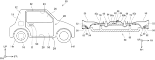
- FIG. 1 is a side view schematically illustrating an overall vehicle 10 , and mainly illustrating a right side of the vehicle 10 in its front-rear direction;
- FIG. 2 is an enlarged view of a part enclosed by a dashed line II in FIG. 1 ;
- FIG. 3 is a sectional view taken along a line in FIG. 2 , illustrating the structure of a cover 52 ;
- FIG. 4 is a sectional view taken along a line IV-IV in FIG. 2 , illustrating the structure of the cover 52 , in particular, the structure of a protrusion 64 provided at a bridge 82 ;
- FIG. 5 is an exploded enlarged view of an outer panel 56 , the cover 52 , and an inner panel 58 ;
- FIG. 6 illustrates the structure of a slope 72 .
- FIG. 7 schematically illustrates a rear end 76 of the outer panel 56 and a rear end 74 of the inner panel 58 .
- a projection of a cover may be formed along an edge of an opening of an outer panel. That is, the projection may extend along the edge of the opening. According to this structure, movement of the opening of the outer panel toward a door handle can be suppressed more effectively.
- the projection of the cover may extend over an entire periphery of the opening of the outer panel. According to this structure, the rigidity of the cover including the projection can relatively be increased. Thus, even if the opening of the outer panel moves toward the door handle due to a higher collision load, the movement can be restricted.
- a plurality of fixing portions fixed to an inner panel by using fasteners, and a protrusion engaging with the inner panel may be further provided in the cover.
- the fixing portions may be provided along an outer edge of the cover.
- the protrusion may be positioned within an area surrounded by the fixing portions.
- two cover openings and a bridge extending between the two cover openings may be further provided in the cover.
- the door handle may be attached to the inner panel through the two openings of the cover.
- the protrusion of the cover may be provided on the bridge. According to this structure, the protrusion is provided relatively near the door handle attached to the inner panel through the cover openings. Thus, the cover can be attached to the inner panel more firmly.
- a slope on a side of the projection that faces the outer panel may be further provided in the cover.
- the slope may be inclined towards an outer side of a vehicle in a direction from the outer panel to the door handle.
- an elastic region of a material for the outer panel and an elastic region of a material for the inner panel may differ from each other.
- the panels may be deformed differently irrespective of a difference in the shapes or structures of the panels. In view of this, this technology can suitably be employed in this structure.
- the material for the inner panel may be a metal
- the material for the outer panel may be a resin
- the materials for the panels are not limited to a combination of the metal and the resin, and may be, for example, a combination of different resins.
- a position of a rear end of the inner panel and a position of a rear end of the outer panel in a vehicle front-rear direction may differ from each other.
- the panels are likely to be deformed differently in the event of deformation of a side door due to a collision load from a rear in the vehicle front-rear direction.
- the inner panel may be deformed more greatly because the inner panel starts to be deformed first.
- a side door 20 of this embodiment is described with reference to the drawings.
- the side door 20 can be employed in a vehicle 10 .
- the vehicle 10 of this embodiment is a so-called automobile that travels on a road.
- a direction FR indicates front in a vehicle front-rear direction
- a direction RH indicates right in a width direction of the vehicle
- a direction UP indicates top in a vertical direction of the vehicle.
- an axis in the vehicle front-rear direction may be referred to simply as “longitudinal axis”.
- the vehicle front-rear direction may be referred to simply as “front-rear direction”.
- the vertical direction of the vehicle may be referred to simply as “vertical direction”.
- the width direction of the vehicle may be referred to simply as “width direction”.
- the vehicle 10 includes a vehicle body 12 and a plurality of wheels.
- the vehicle body 12 is not particularly limited, but is made of a metal material and a resin material.
- the wheels are rotatably attached to the vehicle body 12 .
- the wheels include a pair of front wheels 14 f and a pair of rear wheels 14 r .
- the number of wheels is not limited to four.
- the vehicle 10 of this embodiment has a small size for two occupants, but the size of the vehicle 10 and the number of occupants are not particularly limited.
- the vehicle 10 further includes a traveling motor 16 and a battery unit 18 .
- the traveling motor 16 is connected to the rear wheels 14 r to drive the rear wheels 14 r .
- the traveling motor 16 may drive not only the rear wheels 14 r but at least one of the wheels.
- the battery unit 18 is connected to the traveling motor 16 via a power supply circuit (not illustrated) to supply electric power to the traveling motor 16 .
- the battery unit 18 includes a plurality of secondary battery cells, and is rechargeable with external electric power.
- the vehicle 10 may include another power supply such as a fuel cell unit or a solar panel.
- the vehicle 10 may include another prime mover such as an engine.
- the vehicle 10 further includes the side door 20 .
- the side door 20 is provided on the vehicle body 12 in an openable and closable manner.
- the side door 20 is provided for a user to get into or out of the vehicle 10 .
- the side door 20 is attached to the vehicle body 12 via a hinge (not illustrated), and is swingable in a horizontal direction.
- a window frame 22 is attached to the side door 20 .
- the window frame 22 is positioned at an upper part of the side door 20 .
- the window frame 22 defines a window opening 24 .
- a window glass 26 is provided in the window opening 24 .
- the window glass 26 is openable and closable, and is movable in the vertical direction along the window opening 24 .
- the side door 20 further includes a door handle 50 .
- the door handle 50 is connected to an inner panel 58 described later.
- the door handle 50 is operated by the user to open or close the side door 20 relative to a door opening 28 of the vehicle body 12 .
- the door handle 50 is provided such that the door handle 50 is exposed to an outer side of the vehicle 10 in the width direction.
- the door handle 50 extends in the front-rear direction.
- the door handle 50 is pivotable about an axis along the front-rear direction. A specific structure of the door handle 50 is described later.
- the side door 20 further includes an outer panel 56 and the inner panel 58 .
- the inner panel 58 is positioned on an inner side of the vehicle 10 in the width direction.
- the outer panel 56 is positioned on an outer side in the width direction, and covers the inner panel 58 from the outer side in the width direction.
- the inner panel 58 and the outer panel 56 extend in the vertical direction and the front-rear direction.
- the inner panel 58 and the outer panel 56 are joined together at their front ends and rear ends.
- the inner panel 58 is made of a metal such as steel or aluminum. In another embodiment, the inner panel 58 may be made of a resin.
- the door handle 50 is described here. As described above, the door handle 50 is connected to the inner panel 58 . As illustrated in FIG. 4 , the door handle 50 includes an attachment portion 84 , a plurality of bolts 66 , a handle lever 86 , and a plurality of hinges 70 .
- the attachment portion 84 is a member extending in the front-rear direction and fixed to the inner panel 58 with the bolts 66 . Both ends of the attachment portion 84 are connected to the handle lever 86 via the hinges 70 .
- the handle lever 86 is pivotable about an axis along the front-rear direction of the vehicle 10 via the hinges 70 .
- the outer panel 56 has an opening 30 .
- the opening 30 is provided to face the door handle 50 that is connected to the inner panel 58 , and exposes the door handle 50 to the outer side in the width direction.
- the outer panel 56 is made of a resin.
- the resin material for the outer panel 56 may include a filler such as glass fibers.
- the outer panel 56 may be made of a metal.
- the vehicle 10 further includes a cover 52 .
- the cover 52 has a plurality of upper fixing holes 90
- the inner panel 58 has a plurality of lower fixing holes 92 .
- the lower fixing holes 92 correspond to the upper fixing holes 90 respectively.
- a plurality of fasteners 60 a , 60 b , and 60 c are inserted through the upper fixing holes 90 of the cover 52 and the corresponding lower fixing holes 92 of the inner panel 58 to couple the cover 52 and the inner panel 58 .
- the cover 52 is made of a resin.
- the cover 52 partially closes the opening 30 of the outer panel 56 .
- the cover 52 has a projection 54 .
- the projection 54 is integrated with the cover 52 .
- the projection 54 projects into a space between the door handle 50 and the outer panel 56 .
- the projection 54 can restrict movement of the opening 30 of the outer panel 56 toward the door handle 50 .
- an edge 62 of the opening 30 comes into contact with a side of the projection 54 that faces the outer panel 56 .
- the outer panel 56 in contact with the side of the projection 54 is buckled.
- contact of the edge 62 of the opening 30 of the outer panel 56 with the door handle 50 is suppressed.
- an unexpected erroneous operation on the door handle 50 is restricted, for example.
- the projection 54 of the cover 52 of this embodiment extends along the edge 62 of the opening 30 of the outer panel 56 over the entire periphery of the opening 30 . Therefore, the rigidity of the cover 52 is relatively increased. Thus, even if the opening 30 of the outer panel 56 moves toward the door handle 50 due to a higher collision load, the movement can be restricted.
- the specific structure of the projection 54 may be modified variously.
- the projection 54 only needs to be provided at least in the front-rear direction across the door handle 50 to project into the space between the door handle 50 and the outer panel 56 .
- the shape and size of the projection 54 and the number of projections 54 are not particularly limited.
- the projection 54 may be shaped into a plate that partially projects into the space between the door handle 50 and the outer panel 56 along the edge 62 of the opening 30 of the outer panel 56 on each side in the front-rear direction across the door handle 50 .
- two projections 54 are provided at the front and rear across the door handle 50 .
- the projection 54 can suppress the movement of the opening 30 of the outer panel 56 toward the door handle 50 .
- the cover 52 of this embodiment includes a bridge 82 and a protrusion 64 .
- the bridge 82 extends from top to bottom in the cover 52 , and defines two cover openings 80 a and 80 b .
- the door handle 50 is attached to the inner panel 58 with the bolts 66 through the cover openings 80 a and 80 b .
- the protrusion 64 is provided on the bridge 82 .
- the protrusion 64 has a bending structure to bend in a direction parallel to the longitudinal axis through a hole 88 in the inner panel 58 .
- the protrusion 64 of the cover 52 is caught on the hole 88 of the inner panel 58 such that the cover 52 engages with the inner panel 58 .
- the cover 52 engages with the inner panel 58 at the protrusion 64 in addition to the fixing portions using the fasteners 60 a , 60 b , and 60 c .
- the cover 52 can firmly be attached to the inner panel 58 without increasing the number of necessary fasteners.
- the protrusion 64 may also be provided at any part within an area surrounded by the fixing portions in the cover 52 instead of the bridge 82 unlike this embodiment.
- the door handle 50 is attached to the inner panel 58 through the two cover openings 80 a and 80 b in the cover. That is, the protrusion 64 is provided at a position relatively near the door handle 50 attached to the inner panel 58 through the cover openings 80 a and 80 b .
- the cover 52 can be attached to the inner panel 58 more firmly.
- the cover 52 of this embodiment may further include a slope 72 on the side of the projection 54 that faces the outer panel 56 .
- the slope 72 is inclined towards the outer side of the vehicle 10 in a direction from the outer panel 56 to the door handle 50 .
- the opening 30 of the outer panel 56 moves toward the door handle 50 due to the collision load, the opening 30 is guided to the outer side of the vehicle 10 along the slope 72 . Therefore, even if the edge 62 of the opening 30 of the outer panel 56 goes beyond the projection 54 , contact of the edge 62 with the door handle 50 can be suppressed.
- the slope 72 is provided annularly in the end face of the projection 54 .
- the technology described in this embodiment can similarly be employed in a case where elastic regions of the material for the outer panel 56 and the material for the inner panel 58 differ from each other.
- the inner panel 58 and the outer panel 56 are made of different kinds of material and the elastic regions of the materials differ from each other, the panels are likely to be deformed differently irrespective of a difference in the shapes or structures of the panels.
- the technology described in this embodiment can be employed particularly suitably in the case where the elastic region of the material for the outer panel 56 and the elastic region of the material for the inner panel 58 differ from each other.
- the technology described herein can similarly be employed in a case where the positions of the rear end of the inner panel 58 and the rear end of the outer panel 56 in the front-rear direction of the vehicle 10 differ from each other.
- the panels are likely to be deformed differently in the event of deformation of the side door 20 due to a collision load from the rear.
- the tip of a rear end 76 of the outer panel 56 is positioned behind the tip of a rear end 74 of the inner panel 58 as illustrated in FIG.
- the inner panel 58 is likely to be deformed more greatly because the inner panel 58 starts to be deformed first.
- the technology described in this embodiment can be employed particularly suitably in the case where the positions of the rear end 74 of the inner panel 58 and the rear end 76 of the outer panel 56 in the longitudinal direction differ from each other.
Applications Claiming Priority (2)
| Application Number | Priority Date | Filing Date | Title |
|---|---|---|---|
| JP2020-194173 | 2020-11-24 | ||
| JP2020194173A JP7409293B2 (ja) | 2020-11-24 | 2020-11-24 | 車両用のサイドドア |
Publications (2)
| Publication Number | Publication Date |
|---|---|
| US20220162888A1 US20220162888A1 (en) | 2022-05-26 |
| US11946292B2 true US11946292B2 (en) | 2024-04-02 |
Family
ID=81453187
Family Applications (1)
| Application Number | Title | Priority Date | Filing Date |
|---|---|---|---|
| US17/518,126 Active 2042-08-02 US11946292B2 (en) | 2020-11-24 | 2021-11-03 | Side door for vehicle |
Country Status (4)
| Country | Link |
|---|---|
| US (1) | US11946292B2 (zh) |
| JP (1) | JP7409293B2 (zh) |
| CN (1) | CN114537096B (zh) |
| DE (1) | DE102021130512A1 (zh) |
Citations (14)
| Publication number | Priority date | Publication date | Assignee | Title |
|---|---|---|---|---|
| JPS57168663U (zh) | 1981-04-20 | 1982-10-23 | ||
| JPH05214852A (ja) | 1992-02-05 | 1993-08-24 | Nissan Motor Co Ltd | ドアアウトサイドハンドルの取付構造 |
| US5340174A (en) * | 1993-04-12 | 1994-08-23 | Chrysler Corporation | Mounting arrangement for vehicle door handle |
| US5377450A (en) * | 1993-12-27 | 1995-01-03 | General Motors Corporation | Adjustable door handle assembly |
| US6209366B1 (en) * | 1997-12-17 | 2001-04-03 | Steadfast Corporation | Truck tailgate locking device |
| US20030001399A1 (en) * | 2001-06-29 | 2003-01-02 | Suzuki Motor Corporation | Door handle assembling construction |
| US20070001479A1 (en) * | 2005-06-29 | 2007-01-04 | Mitsubishi Jidosha Kogyo Kabushiki Kaisha | Vehicle door |
| JP2007177475A (ja) | 2005-12-27 | 2007-07-12 | Suzuki Motor Corp | ドアアウトサイドハンドルのロック解除防止構造 |
| US20110308172A1 (en) * | 2007-08-01 | 2011-12-22 | Johnson Controls Gmbh & Co. Kg | Door module for a vehicle door, and mounting method |
| JP2013163441A (ja) | 2012-02-10 | 2013-08-22 | Mitsubishi Automob Eng Co Ltd | 車両用ドア |
| US20130263518A1 (en) * | 2012-04-10 | 2013-10-10 | Toyota Engineering & Manufacturing North America, Inc. | Vehicle door trim panel |
| JP2018001858A (ja) | 2016-06-29 | 2018-01-11 | トヨタ車体株式会社 | 車両の樹脂製ドア |
| US20190160921A1 (en) | 2017-11-30 | 2019-05-30 | Toyota Boshoku Kabushiki Kaisha | Vehicular door |
| US20200232260A1 (en) * | 2019-01-18 | 2020-07-23 | Dr. Ing. H.C. F. Porsche Aktiengesellschaft | Inside door opener arrangement |
Family Cites Families (6)
| Publication number | Priority date | Publication date | Assignee | Title |
|---|---|---|---|---|
| JP4259094B2 (ja) * | 2002-11-07 | 2009-04-30 | マツダ株式会社 | 車両の上部車体構造 |
| JP5751451B2 (ja) * | 2011-11-18 | 2015-07-22 | トヨタ紡織株式会社 | 車両用衝撃吸収構造 |
| JP5826736B2 (ja) * | 2012-11-21 | 2015-12-02 | 株式会社豊田自動織機 | 車両用ドアの補強構造 |
| JP5934159B2 (ja) * | 2013-09-02 | 2016-06-15 | 本田技研工業株式会社 | ドアアウタハンドル |
| US20150368936A1 (en) * | 2014-06-24 | 2015-12-24 | Ford Global Technologies, Llc | Distortion free door handle |
| JP6288378B2 (ja) * | 2016-01-28 | 2018-03-07 | 新日鐵住金株式会社 | パネル状成形品、車両用ドア、及び、パネル状成形品の製造方法 |
-
2020
- 2020-11-24 JP JP2020194173A patent/JP7409293B2/ja active Active
-
2021
- 2021-10-21 CN CN202111225488.4A patent/CN114537096B/zh active Active
- 2021-11-03 US US17/518,126 patent/US11946292B2/en active Active
- 2021-11-22 DE DE102021130512.8A patent/DE102021130512A1/de active Pending
Patent Citations (16)
| Publication number | Priority date | Publication date | Assignee | Title |
|---|---|---|---|---|
| JPS57168663U (zh) | 1981-04-20 | 1982-10-23 | ||
| JPH05214852A (ja) | 1992-02-05 | 1993-08-24 | Nissan Motor Co Ltd | ドアアウトサイドハンドルの取付構造 |
| US5340174A (en) * | 1993-04-12 | 1994-08-23 | Chrysler Corporation | Mounting arrangement for vehicle door handle |
| US5377450A (en) * | 1993-12-27 | 1995-01-03 | General Motors Corporation | Adjustable door handle assembly |
| US6209366B1 (en) * | 1997-12-17 | 2001-04-03 | Steadfast Corporation | Truck tailgate locking device |
| US20030001399A1 (en) * | 2001-06-29 | 2003-01-02 | Suzuki Motor Corporation | Door handle assembling construction |
| US20070001479A1 (en) * | 2005-06-29 | 2007-01-04 | Mitsubishi Jidosha Kogyo Kabushiki Kaisha | Vehicle door |
| JP2007177475A (ja) | 2005-12-27 | 2007-07-12 | Suzuki Motor Corp | ドアアウトサイドハンドルのロック解除防止構造 |
| US20110308172A1 (en) * | 2007-08-01 | 2011-12-22 | Johnson Controls Gmbh & Co. Kg | Door module for a vehicle door, and mounting method |
| JP2013163441A (ja) | 2012-02-10 | 2013-08-22 | Mitsubishi Automob Eng Co Ltd | 車両用ドア |
| US20130263518A1 (en) * | 2012-04-10 | 2013-10-10 | Toyota Engineering & Manufacturing North America, Inc. | Vehicle door trim panel |
| JP2018001858A (ja) | 2016-06-29 | 2018-01-11 | トヨタ車体株式会社 | 車両の樹脂製ドア |
| US20190160921A1 (en) | 2017-11-30 | 2019-05-30 | Toyota Boshoku Kabushiki Kaisha | Vehicular door |
| JP2019098888A (ja) | 2017-11-30 | 2019-06-24 | トヨタ紡織株式会社 | 乗物用ドア |
| US20200232260A1 (en) * | 2019-01-18 | 2020-07-23 | Dr. Ing. H.C. F. Porsche Aktiengesellschaft | Inside door opener arrangement |
| DE102019101293A1 (de) * | 2019-01-18 | 2020-07-23 | Dr. Ing. H.C. F. Porsche Aktiengesellschaft | Türinnenöffneranordnung |
Also Published As
| Publication number | Publication date |
|---|---|
| DE102021130512A1 (de) | 2022-05-25 |
| JP7409293B2 (ja) | 2024-01-09 |
| US20220162888A1 (en) | 2022-05-26 |
| CN114537096A (zh) | 2022-05-27 |
| CN114537096B (zh) | 2023-08-01 |
| JP2022082971A (ja) | 2022-06-03 |
Similar Documents
| Publication | Publication Date | Title |
|---|---|---|
| JP5443397B2 (ja) | 車両用ドア構造体 | |
| JP5303211B2 (ja) | 車両用ドア構造体およびその製造方法 | |
| US20190256154A1 (en) | Vehicle side portion structure | |
| US8336666B2 (en) | Hood hinge | |
| US20200101854A1 (en) | Vehicle body front structure | |
| JP2009083687A (ja) | 自動車の前部構造 | |
| KR20150085089A (ko) | 차량용 후드 구조 | |
| CN112298054A (zh) | 用于车身侧部的传感器附接结构 | |
| US20230311999A1 (en) | Vehicle base structure | |
| JPH0930452A (ja) | 自動車用サイドシル補強構造 | |
| US11946292B2 (en) | Side door for vehicle | |
| JP2006273296A (ja) | センタピラーレス車のロッカ構造 | |
| JP3646583B2 (ja) | フロントサイドメンバ構造 | |
| US20220169312A1 (en) | Dash Panel Structure for Vehicle | |
| CN213831293U (zh) | 一种提升偏置碰性能的前门结构 | |
| JPH11321718A (ja) | フェンダ構造 | |
| CN213799905U (zh) | 一种汽车a柱总成及汽车 | |
| JP7272984B2 (ja) | 車両 | |
| KR20150035791A (ko) | 측부 충격의 경우에 중앙 필러 구조물의 변형을 안내할 수 있는 추가 보강부를 포함하는 자동차 | |
| JPH11255153A (ja) | 車両のボンネット構造 | |
| US10717349B1 (en) | Vehicle doors including torsion bar support assemblies | |
| CN208698902U (zh) | 一种汽车中滑门门槛安装结构 | |
| JPH0631011B2 (ja) | 自動車のリツド構造 | |
| JP6708976B2 (ja) | 車両用バックドア | |
| JPH1178524A (ja) | 車両のドア構造 |
Legal Events
| Date | Code | Title | Description |
|---|---|---|---|
| AS | Assignment |
Owner name: TOYOTA JIDOSHA KABUSHIKI KAISHA, JAPAN Free format text: ASSIGNMENT OF ASSIGNORS INTEREST;ASSIGNORS:YANAKA, AKIHIRO;KURACHI, SHINJI;KOMATSU, TAKANORI;SIGNING DATES FROM 20210830 TO 20210922;REEL/FRAME:058009/0163 |
|
| FEPP | Fee payment procedure |
Free format text: ENTITY STATUS SET TO UNDISCOUNTED (ORIGINAL EVENT CODE: BIG.); ENTITY STATUS OF PATENT OWNER: LARGE ENTITY |
|
| STPP | Information on status: patent application and granting procedure in general |
Free format text: DOCKETED NEW CASE - READY FOR EXAMINATION |
|
| STPP | Information on status: patent application and granting procedure in general |
Free format text: NON FINAL ACTION MAILED |
|
| STPP | Information on status: patent application and granting procedure in general |
Free format text: RESPONSE TO NON-FINAL OFFICE ACTION ENTERED AND FORWARDED TO EXAMINER |
|
| STPP | Information on status: patent application and granting procedure in general |
Free format text: NOTICE OF ALLOWANCE MAILED -- APPLICATION RECEIVED IN OFFICE OF PUBLICATIONS |
|
| STPP | Information on status: patent application and granting procedure in general |
Free format text: PUBLICATIONS -- ISSUE FEE PAYMENT VERIFIED |
|
| STCF | Information on status: patent grant |
Free format text: PATENTED CASE |