US11651179B2 - Optical articles and systems interacting with the same - Google Patents
Optical articles and systems interacting with the same Download PDFInfo
- Publication number
- US11651179B2 US11651179B2 US16/486,311 US201716486311A US11651179B2 US 11651179 B2 US11651179 B2 US 11651179B2 US 201716486311 A US201716486311 A US 201716486311A US 11651179 B2 US11651179 B2 US 11651179B2
- Authority
- US
- United States
- Prior art keywords
- retroreflective
- retroreflective elements
- article
- optical
- instances
- Prior art date
- Legal status (The legal status is an assumption and is not a legal conclusion. Google has not performed a legal analysis and makes no representation as to the accuracy of the status listed.)
- Active
Links
- 230000003287 optical effect Effects 0.000 title claims abstract description 116
- 230000008859 change Effects 0.000 claims description 11
- 230000002441 reversible effect Effects 0.000 claims description 5
- 230000005855 radiation Effects 0.000 claims description 3
- 230000004044 response Effects 0.000 claims description 3
- 235000013372 meat Nutrition 0.000 abstract 1
- 238000000576 coating method Methods 0.000 description 27
- 238000013461 design Methods 0.000 description 26
- 239000011248 coating agent Substances 0.000 description 24
- 210000000349 chromosome Anatomy 0.000 description 20
- 238000000034 method Methods 0.000 description 20
- 238000001514 detection method Methods 0.000 description 16
- 230000004438 eyesight Effects 0.000 description 13
- 229920002799 BoPET Polymers 0.000 description 10
- 230000006870 function Effects 0.000 description 10
- 238000010276 construction Methods 0.000 description 9
- 230000002068 genetic effect Effects 0.000 description 8
- 239000000470 constituent Substances 0.000 description 7
- 239000011521 glass Substances 0.000 description 7
- 239000000463 material Substances 0.000 description 7
- BUHVIAUBTBOHAG-FOYDDCNASA-N (2r,3r,4s,5r)-2-[6-[[2-(3,5-dimethoxyphenyl)-2-(2-methylphenyl)ethyl]amino]purin-9-yl]-5-(hydroxymethyl)oxolane-3,4-diol Chemical compound COC1=CC(OC)=CC(C(CNC=2C=3N=CN(C=3N=CN=2)[C@H]2[C@@H]([C@H](O)[C@@H](CO)O2)O)C=2C(=CC=CC=2)C)=C1 BUHVIAUBTBOHAG-FOYDDCNASA-N 0.000 description 6
- 238000013459 approach Methods 0.000 description 6
- 238000005457 optimization Methods 0.000 description 6
- 238000003491 array Methods 0.000 description 5
- 238000005259 measurement Methods 0.000 description 5
- 238000012986 modification Methods 0.000 description 5
- 230000004048 modification Effects 0.000 description 5
- 230000010287 polarization Effects 0.000 description 5
- 229920000139 polyethylene terephthalate Polymers 0.000 description 5
- 239000000758 substrate Substances 0.000 description 5
- 238000000411 transmission spectrum Methods 0.000 description 5
- 238000012512 characterization method Methods 0.000 description 4
- 230000000052 comparative effect Effects 0.000 description 4
- 230000000694 effects Effects 0.000 description 4
- 238000002329 infrared spectrum Methods 0.000 description 4
- 230000000877 morphologic effect Effects 0.000 description 4
- 238000012545 processing Methods 0.000 description 4
- 230000000007 visual effect Effects 0.000 description 4
- OCKGFTQIICXDQW-ZEQRLZLVSA-N 5-[(1r)-1-hydroxy-2-[4-[(2r)-2-hydroxy-2-(4-methyl-1-oxo-3h-2-benzofuran-5-yl)ethyl]piperazin-1-yl]ethyl]-4-methyl-3h-2-benzofuran-1-one Chemical compound C1=C2C(=O)OCC2=C(C)C([C@@H](O)CN2CCN(CC2)C[C@H](O)C2=CC=C3C(=O)OCC3=C2C)=C1 OCKGFTQIICXDQW-ZEQRLZLVSA-N 0.000 description 3
- 241000282412 Homo Species 0.000 description 3
- 230000008901 benefit Effects 0.000 description 3
- 230000001788 irregular Effects 0.000 description 3
- 230000035772 mutation Effects 0.000 description 3
- 102000004169 proteins and genes Human genes 0.000 description 3
- 108090000623 proteins and genes Proteins 0.000 description 3
- 230000010076 replication Effects 0.000 description 3
- 238000007655 standard test method Methods 0.000 description 3
- 239000000725 suspension Substances 0.000 description 3
- 238000012360 testing method Methods 0.000 description 3
- 238000012549 training Methods 0.000 description 3
- 238000010521 absorption reaction Methods 0.000 description 2
- 239000008199 coating composition Substances 0.000 description 2
- 238000004891 communication Methods 0.000 description 2
- 238000005516 engineering process Methods 0.000 description 2
- 238000011156 evaluation Methods 0.000 description 2
- 238000002474 experimental method Methods 0.000 description 2
- 239000004744 fabric Substances 0.000 description 2
- 230000036541 health Effects 0.000 description 2
- 238000010801 machine learning Methods 0.000 description 2
- 239000000203 mixture Substances 0.000 description 2
- 230000008569 process Effects 0.000 description 2
- 230000001105 regulatory effect Effects 0.000 description 2
- 238000009877 rendering Methods 0.000 description 2
- 238000000926 separation method Methods 0.000 description 2
- 238000004513 sizing Methods 0.000 description 2
- 238000001228 spectrum Methods 0.000 description 2
- 239000000126 substance Substances 0.000 description 2
- 238000012706 support-vector machine Methods 0.000 description 2
- LAVARTIQQDZFNT-UHFFFAOYSA-N 1-(1-methoxypropan-2-yloxy)propan-2-yl acetate Chemical compound COCC(C)OCC(C)OC(C)=O LAVARTIQQDZFNT-UHFFFAOYSA-N 0.000 description 1
- NQBXSWAWVZHKBZ-UHFFFAOYSA-N 2-butoxyethyl acetate Chemical compound CCCCOCCOC(C)=O NQBXSWAWVZHKBZ-UHFFFAOYSA-N 0.000 description 1
- 230000009471 action Effects 0.000 description 1
- 230000004075 alteration Effects 0.000 description 1
- 239000011324 bead Substances 0.000 description 1
- 230000033228 biological regulation Effects 0.000 description 1
- 230000005540 biological transmission Effects 0.000 description 1
- 238000013480 data collection Methods 0.000 description 1
- 238000003066 decision tree Methods 0.000 description 1
- 230000010339 dilation Effects 0.000 description 1
- 239000002270 dispersing agent Substances 0.000 description 1
- 239000006185 dispersion Substances 0.000 description 1
- 238000005315 distribution function Methods 0.000 description 1
- 238000001035 drying Methods 0.000 description 1
- 230000002708 enhancing effect Effects 0.000 description 1
- 230000003628 erosive effect Effects 0.000 description 1
- 238000012854 evaluation process Methods 0.000 description 1
- 238000000605 extraction Methods 0.000 description 1
- 239000005337 ground glass Substances 0.000 description 1
- 229910052736 halogen Inorganic materials 0.000 description 1
- 150000002367 halogens Chemical class 0.000 description 1
- 238000003384 imaging method Methods 0.000 description 1
- 230000003094 perturbing effect Effects 0.000 description 1
- KJOLVZJFMDVPGB-UHFFFAOYSA-N perylenediimide Chemical compound C=12C3=CC=C(C(NC4=O)=O)C2=C4C=CC=1C1=CC=C2C(=O)NC(=O)C4=CC=C3C1=C42 KJOLVZJFMDVPGB-UHFFFAOYSA-N 0.000 description 1
- 238000001556 precipitation Methods 0.000 description 1
- 238000007639 printing Methods 0.000 description 1
- 230000000135 prohibitive effect Effects 0.000 description 1
- 238000007650 screen-printing Methods 0.000 description 1
- 230000035945 sensitivity Effects 0.000 description 1
- 238000010998 test method Methods 0.000 description 1
- 238000009941 weaving Methods 0.000 description 1
Images


Classifications
-
- G—PHYSICS
- G06—COMPUTING; CALCULATING OR COUNTING
- G06K—GRAPHICAL DATA READING; PRESENTATION OF DATA; RECORD CARRIERS; HANDLING RECORD CARRIERS
- G06K19/00—Record carriers for use with machines and with at least a part designed to carry digital markings
- G06K19/06—Record carriers for use with machines and with at least a part designed to carry digital markings characterised by the kind of the digital marking, e.g. shape, nature, code
- G06K19/06009—Record carriers for use with machines and with at least a part designed to carry digital markings characterised by the kind of the digital marking, e.g. shape, nature, code with optically detectable marking
- G06K19/06037—Record carriers for use with machines and with at least a part designed to carry digital markings characterised by the kind of the digital marking, e.g. shape, nature, code with optically detectable marking multi-dimensional coding
-
- G—PHYSICS
- G02—OPTICS
- G02B—OPTICAL ELEMENTS, SYSTEMS OR APPARATUS
- G02B5/00—Optical elements other than lenses
- G02B5/12—Reflex reflectors
-
- G—PHYSICS
- G02—OPTICS
- G02B—OPTICAL ELEMENTS, SYSTEMS OR APPARATUS
- G02B5/00—Optical elements other than lenses
- G02B5/12—Reflex reflectors
- G02B5/122—Reflex reflectors cube corner, trihedral or triple reflector type
- G02B5/124—Reflex reflectors cube corner, trihedral or triple reflector type plural reflecting elements forming part of a unitary plate or sheet
-
- G—PHYSICS
- G02—OPTICS
- G02B—OPTICAL ELEMENTS, SYSTEMS OR APPARATUS
- G02B5/00—Optical elements other than lenses
- G02B5/30—Polarising elements
- G02B5/3025—Polarisers, i.e. arrangements capable of producing a definite output polarisation state from an unpolarised input state
- G02B5/3033—Polarisers, i.e. arrangements capable of producing a definite output polarisation state from an unpolarised input state in the form of a thin sheet or foil, e.g. Polaroid
- G02B5/3041—Polarisers, i.e. arrangements capable of producing a definite output polarisation state from an unpolarised input state in the form of a thin sheet or foil, e.g. Polaroid comprising multiple thin layers, e.g. multilayer stacks
- G02B5/305—Polarisers, i.e. arrangements capable of producing a definite output polarisation state from an unpolarised input state in the form of a thin sheet or foil, e.g. Polaroid comprising multiple thin layers, e.g. multilayer stacks including organic materials, e.g. polymeric layers
-
- G—PHYSICS
- G02—OPTICS
- G02B—OPTICAL ELEMENTS, SYSTEMS OR APPARATUS
- G02B5/00—Optical elements other than lenses
- G02B5/30—Polarising elements
- G02B5/3025—Polarisers, i.e. arrangements capable of producing a definite output polarisation state from an unpolarised input state
-
- G—PHYSICS
- G06—COMPUTING; CALCULATING OR COUNTING
- G06K—GRAPHICAL DATA READING; PRESENTATION OF DATA; RECORD CARRIERS; HANDLING RECORD CARRIERS
- G06K19/00—Record carriers for use with machines and with at least a part designed to carry digital markings
- G06K19/06—Record carriers for use with machines and with at least a part designed to carry digital markings characterised by the kind of the digital marking, e.g. shape, nature, code
- G06K2019/06215—Aspects not covered by other subgroups
- G06K2019/0629—Holographic, diffractive or retroreflective recording
Definitions
- the present disclosure relates to optical articles. More specifically, the present disclosure relates to optical articles that are configured to be readable by optical systems.
- One exemplary application for such optical articles is when the optical article is disposed on a substrate, such as, for example, infrastructure, wearables, and vehicles, where such optical article is readable by an optical system.
- optical articles and substrates such as infrastructure, wearables, vehicles, and other articles, containing such optical articles.
- improved systems for interacting with such optical articles There is also a need for improved systems for interacting with such optical articles.
- Retroreflective articles redirect light incident on the article back toward its source. This property led to many practical applications of retroreflective articles in the areas of traffic and personal safety. Retroreflective articles are currently used for traffic signs, car license plates, pavement markings, construction zone cones and barrels, and high visibility trim on clothing worn by workers.
- Visual tags offer a solution to limitations of other types of optical tags.
- visual tags require a large power of computation due to the image processing needs in order to differentiate the tag from surrounding background images.
- Systems that interact with optical articles include computer vision systems, or optical systems. These type of systems include methods for acquiring, analyzing, and understanding images. Applications of these systems include robotics, face recognition, image search, machine vision, remote sensing, surveillance, autonomous vehicles, and object detection to name a few. Some examples of applications of object detection include vehicle vision systems, autonomous vehicles, as well as worker safety.
- High visibility garments i.e., garments with retro-reflective materials
- Current optical systems are based on collecting a large amount of training data, having human experts annotate it and then training a model to detect the specific object of interest. This collection and annotation of data is time consuming and cost prohibitive.
- the present disclosure provides a number of advantages over existing optical articles and systems used therewith.
- the present disclosure provides uniquely patterned, data rich optical articles that can readily convey information to a system, such as an optical system, to allow identification and tracking of users wearing such optical articles.
- the present disclosure provides an optical article comprising a data rich plurality of retroreflective elements that are configured in a spatially defined arrangement, wherein the plurality of retroreflective elements comprise retroreflective elements having at least two different retroreflective properties, wherein data rich means information that is readily machine interpretable.
- the data rich plurality of retroreflective elements are configured in a repeating spatially defined arrangement such that the information is interpretable even when the portion of the retroreflective elements are occluded.
- the optical article is a deformable optical article. In some instances, the deformation is at least one of a shrinkage or an expansion.
- the deformation causes a spacing change between at least two of the retroreflective elements. In some instances, the deformation is reversible.
- the at least two different retroreflective properties are at least two different retroreflective intensity values. In some instances, the at least two different retroreflective properties are at least two different wavelengths. In some instances, the at least two different retroreflective properties have at least two different polarization states. In some instances, the at least two different retroreflective properties at least two different phase retardations.
- the aforementioned retroreflective property changes in response to a change in condition.
- the change in condition is at least one of a change in thermal, moisture, mechanical deformation, or radiation.
- the retroreflective elements are individually sized and separated from one another such that each individual retroreflective element is resolvable at desired distances from the optical article.
- the spatially defined arrangement comprises geometric arrangement in which the retroreflective elements are positioned with a distance from their neighboring retroreflective elements, and wherein the retroreflective elements have a periodicity from one element to another within the spatially defined arrangement.
- the periodicity is a regular periodicity.
- the periodicity is an irregular periodicity.
- the spatially defined arrangement is rotationally insensitive.
- a number of geometric arrangements are required per spatially defined arrangement depends on a required quality of fit.
- the retroreflective elements are positioned from their nearest neighboring retroreflective elements by a characteristic distance.
- the retroreflective elements have a characteristic ratio of size to distance to neighboring retroreflective elements that is invariant with viewing angle.
- the optical article further comprises a printed layer disposed on the outer surface of at least a portion of the retroreflective elements.
- the retroreflective properties are detectable in the infrared spectrum with a computer vision system.
- the optical article is disposed on a substrate selected from at least one of infrastructure, wearables, and vehicles.
- the present disclosure provides a fabric comprising the aforementioned articles.
- the present disclosure also includes a system comprising any of the aforementioned articles, an optical system, and an inference engine for interpreting and classifying the plurality of retroreflective elements wherein the optical system feeds data to the inference engine.
- the article is disposed on at least one of infrastructure, targets, wearables, and vehicles.
- the optical system is part of a vehicle, and further wherein the vehicle uses the information as an input to an autonomous driving module. In some instances, the vehicle uses the information to provide human language feedback to the driver. In some instances, the vehicle uses the information to provide at least one of haptic, audible or visual feedback to the driver.
- the data rich plurality of retroreflective elements is visible in the infrared spectrum with a computer vision system.
- the information related to the data rich plurality of retroreflective articles comprises at least one of road workers expected, pedestrians expected, construction workers expected, students expected, emergency responder workers expected.
- the inference engine is locally stored as a component of the optical system.
- the optical system communicates with the inference engine using a wireless communication protocol.
- the inference engine includes a look up table with assigned meanings associated with specific patterns of data rich plurality of retroreflective elements.
- the inference engine includes a look up table.
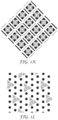
- FIGS. 1 a to 1 m show various patterns of retroreflective elements included in the presently disclosed optical articles.
- FIGS. 2 a and 2 b show the presently disclosed optical articles disposed on an objects.
- FIG. 3 shows a rendered image of an environment including the shape in presence of distractors produced by a software and an automatic extraction of the regions of interest (ROI) for the shapes from the synthetically generated image according to some embodiments of the presently disclosed system.
- ROI regions of interest
- FIG. 4 depicts a flowchart describing the steps for evaluating the saliency of an input shape using synthetically generated data according to some embodiments of the presently disclosed system.
- FIG. 5 depicts an image of the object of interest (carrier pattern).
- the images are annotated with a bounding box located around the object as shown in (a).
- a machine learning model is trained to disambiguate between this carrier pattern and other objects found in the environment in (b).
- FIG. 6 depicts an exemplary modifications to a carrier pattern.
- the carrier pattern is shown in (a).
- a modification to the pattern can include a gap introduced into the middle of the strips as shown in (b) or repeating gaps in the form of a segmented trim like that shown in (c).
- FIG. 7 depicts images of instances of different sub-categories of the carrier pattern.
- FIGS. 8 a and 8 b depict an exemplary system for image processing useful in some embodiments in the presently disclosed system.
- FIG. 9 shows an overview of an evaluation process of possible shape arrangements useful in algorithms that can be used in some embodiments of the presently disclosed system.
- FIG. 10 shows a design with a fit (or saliency) score of 0.752332, produced after 1484 generations of the genetic algorithm useful in some embodiments in the presently disclosed system.
- FIG. 11 shows the design from FIG. 10 , rendered onto 3D vest model by an algorithm useful in some embodiments in the presently disclosed system.
- FIG. 12 shows an exemplary function that can be used for optimizing designs in the presently disclosed system.
- FIG. 13 depicts an exemplary genetic algorithm useful in some embodiments in the presently disclosed system.
- FIG. 14 depicts an embodiment for a workflow for a single image instance useful in some embodiments in the presently disclosed system.
- FIG. 15 depicts an embodiment for a workflow for an input image useful in some embodiments in the presently disclosed system.
- FIG. 16 shows transmission spectra for coated films related to Examples 2A-2D and Comparative Example 2.
- FIG. 17 shows retroreflected pixel intensity for Examples 2A-2D.
- FIG. 18 shows transmission spectra for coated films related to Examples 3A-3C.
- object part detector means a detector that can find individual parts of an object in image/video instead of finding the whole object itself.
- over glow means the amount and position of detected retroreflective intensity in a retroreflective image outside of the actual boundaries of the retroreflective elements being viewed in the retroreflective image.
- the present disclosure provides an optical article comprising a data rich plurality of retroreflective elements that are configured in a spatially defined arrangement.
- the plurality of retroreflective elements includes retroreflective elements, where these plurality of retroreflective elements have at least two different retroreflective properties.
- the at least two different retroreflective properties are at least two different retroreflective intensity values. In some instances, the at least two different retroreflective properties are at least two different wavelengths. In some instances, the at least two different retroreflective properties have at least two different polarization states. In some instances, the at least two different retroreflective properties at least two different phase retardations.
- the data rich plurality of retroreflective elements are configured in a repeating spatially defined arrangement such that the information is interpretable even when the portion of the retroreflective elements are occluded.
- FIG. 1 a illustrates the effect of occlusion and pattern replication.
- the upper-left quadrant shows a sample base pattern of retroreflective elements.
- imaging that the patterns is identifiable if both of the circles are visible; the upper-right quadrant shows the same base pattern with one replication; in the lower-left quadrant of FIG. 1 a a white object has occluded one of the elements in the pattern.
- the occlusion results in an inability to detect the pattern.
- a white object is occluding one of the elements of the pattern but due to the replication there are still sufficient elements for detection of pattern of the optical article by a system, such a visions detection system.
- Various patterns of retroreflective elements can be used in the present disclosure, such as the exemplary designs shown in FIGS. 1 b to 1 m.
- the classifier in a system is based on checking the number of retroreflective elements in the pattern against a minimum required number of retroreflective elements, a pattern containing at least one more element than the specified minimum will be detectable under partial occlusion.
- a classifier in a system, such a vision detection system looking for a specific number of retroreflective elements is not robust when at least one of the retroreflective elements in the pattern is occluded.
- the plurality of retroreflective elements can have the same or different shapes.
- Useful shapes for individual retroreflective elements includes, but are not limited to, circles, stars, squares, polygons, curved and irregular shapes, and the like.
- These individual retroreflective elements can be arranged in a mathematical way of arranging shapes such that the arrangement can be detected independent of the individual component shapes, optionally the individual component shapes could add additional information.
- Mathematical arrangement refers to a scheme for sizing and spacing apart the components of the resulting optical article.
- retroreflective elements or resulting optical articles may be either standalone or may be repeating to increase robustness to partial occlusion. If the elements or articles are small, repetition may be required for robust detection, if the optical article is large it is likely to be robust to partial occlusion due to a subset being visible.
- any number of the component shapes could be engineered to selectively reflect light of different wavelengths and/or polarization.
- retroreflective elements with properties sufficient to meet regulatory standards (e.g., ANSI compliant material) but a subset of the optical article is constructed such that it has special optical properties (e.g., wavelengths and/or polarization reflected) such that a system (such as a computer vision system) can discriminate between these sections of the optical article and the rest of the optical article or objects on which it is mounted.
- regulatory standards e.g., ANSI compliant material
- a system such as a computer vision system
- One example of the utility of such a construction might be, if to be regulatory compliant gaps in the retroreflective elements had to be less than X mm, but computer vision system detection necessitated gaps greater than X mm.
- the construction of the retroreflective elements allowed the computer vision system to only see a subset of the retroreflective elements but the entire (or at least a portion of the optical article or retroreflective elements) is sufficient to meet standards because the resulting optical article is reflective to light in a spectrum that is detectable by humans.
- the number of unique retroreflective elements in the optical article should be robust to deformation and perspective changes up to the point where retroreflective elements become completely occluded or they begin to merge together versus density of bright pixels.
- the spacing and feature size of the retroreflective elements (or shapes) comprising the optical article will likely need to factor in over-glow.
- One optional construction of the present disclosure might include retroreflective elements that are constructed of more than one level of reflective material so as to reduce effect of over-glow.
- the outer edge of the retroreflective elements might be constructed from lower R A material as compared to the internal portion of the retroreflective elements.
- a minimum measured difference in R A such as at least a difference of 5%, 10%, 20%, 50% or more, is useful.
- the retroreflective elements can be manufactured by any number of methods including but not limited to: screen printing, weaving, stitching, and the like.
- the optical article is a deformable optical article.
- the deformation is caused by shrinkage, expansion, or both.
- the deformation causes a spacing change between at least two of the retroreflective elements.
- the deformation is reversible.
- the aforementioned retroreflective property changes in response to a change in condition.
- a change in condition that could cause a change in at least one of the retroreflective properties of the plurality of retroreflective elements could be a change in thermal, moisture, mechanical deformation, or radiation.
- Thermal changes could be changes in ambient temperature, for example.
- Exemplary moisture changes include changes in ambient humidity or the presence of precipitation in an environment in which the optical article is being used.
- Mechanical deformation could include, for example, wrinkling of a garment on which the optical article is mounted.
- the retroreflective elements are individually sized and separated from one another such that each individual retroreflective element is resolvable at desired distances from the optical article.
- the spatially defined arrangement comprises geometric arrangement in which the retroreflective elements are positioned with a distance from their neighboring retroreflective elements, and wherein the retroreflective elements have a periodicity from one element to another within the spatially defined arrangement.
- the periodicity is a regular periodicity.
- the periodicity is an irregular periodicity.
- the spatially defined arrangement is rotationally insensitive.
- a number of geometric arrangements are required per spatially defined arrangement depends on a required quality of fit.
- the retroreflective elements are positioned from their nearest neighboring retroreflective elements by a characteristic distance.
- the retroreflective elements have a characteristic ratio of size to distance to neighboring retroreflective elements that is invariant with viewing angle.
- the optical article further comprises a printed layer disposed on the outer surface of at least a portion of the retroreflective elements.
- the retroreflective properties are detectable in the infrared spectrum.
- the optical article is disposed on a substrate selected from at least one of infrastructure, wearables, and vehicles.
- the present disclosure provides a fabric comprising the aforementioned articles.
- the present disclosure also includes a system comprising any of the aforementioned articles, an optical system, and an inference engine for interpreting and classifying the plurality of retroreflective elements wherein the optical system feeds data to the inference engine.
- the article is disposed on at least one of infrastructure, targets, wearables, and vehicles.
- the optical system is part of a vehicle, and further wherein the vehicle uses the information as an input to an autonomous driving module. In some instances, the vehicle uses the information to provide human language feedback to the driver. In some instances, the vehicle uses the information to provide at least one of haptic, audible or visual feedback to the driver.
- the data rich plurality of retroreflective elements is visible in the infrared spectrum to a computer vision system.
- the information related to the data rich plurality of retroreflective articles comprises at least one of road workers expected, pedestrians expected, construction workers expected, students expected, emergency responder workers expected.
- the inference engine is locally stored as a component of the optical system.
- the optical system communicates with the inference engine using a wireless communication protocol.
- the inference engine and the optical system can include various features and steps as disclosed in the following section on methods and systems useful in the present disclosure.
- the presently disclosed system is useful for various applications.
- the presently disclosed system utilizes the presently disclosed optical article for the purpose of simplifying and enhancing detection capabilities of a system, such as a computer vision pedestrian detection, which allows for the system to determine location, identification, and/or pose of an individual wearing a garment, accessory or other objects on which the optical article is disposed.
- the data rich content in the plurality of retroreflective elements aids in simplification of the task of pedestrian detection by reducing the number of distractors that the optical system needs to evaluate by first thresholding the image based on properties of the optical (such as, for example, intensity and/or color spectrum of the light returned) and then evaluating those segmented regions for meaningful shapes (or patterns) based on the design of the garment, accessory or other article on which the optical article is disposed and likely poses of the wearer.
- properties of the optical such as, for example, intensity and/or color spectrum of the light returned
- the presently disclosed system includes at least one camera, a light source (such as, for example, vehicle headlights, or other visible, NIR, or FIR light sources), and the presently disclosed optical articles.
- the presently disclosed system utilizes the pattern of light returned from the optical article to identify the object on which the optical article is disposed, infer pose, position, likelihood of intersection, etc.
- One possible embodiment might utilize a garment design, such as those illustrated in FIGS. 2 a and 2 b .
- a frontal view of the garment has a different number and pattern of visible optical articles having a plurality of retroreflective elements than a profile view of the garment. If the optical articles on the garment are of a known size (for example, if the chevrons in this case are all 6 inches in length) then the system could infer relative distance and position of the wearer from the camera based on projected size and position.
- the present disclosure includes a system and method for automatically evaluating the saliency of design shapes, such as optical articles and a plurality of retroreflective elements included therein, for an application environment without having to collect real world data (images/videos) of such shapes.
- design shapes such as optical articles and a plurality of retroreflective elements included therein
- the sequence of steps to perform this methodology is depicted in FIG. 3 and described here:
- the input to the system is the shape of interest, such as optical articles and a plurality of retroreflective elements included therein.
- the distractor set can include highway information sign, speed limit sign, cones, barrels, and the like.
- the design shape (such as optical articles and a plurality of retroreflective elements included therein) placed on an object of interest (such as infrastructure, garments, accessories, and the like) and distractor set is input into an algorithm or software for generating a synthetic dataset of images and videos.
- FIG. 3 ( a ) shows a sample rendered image of a highway worker wearing a high visibility garment with an exemplary optical article of the present disclosure as the design shape in the frontal portion of his garment.
- the regions of interest (ROI) corresponding to the design shape (e.g., optical articles and a plurality of retroreflective elements included therein) and the distractor are extracted from the images.
- FIG. 3 ( b ) shows one such example of ROIs extracted from a rendered image. This process can be automated using knowledge about the 3D model provided for the rendering of the environment.
- features characterizing their properties like appearance, shape, texture, geometry are computed e.g. shape context, histogram of oriented gradients, area, etc.
- the computed features are then input into an algorithm, an example of which is shown in FIG. 4 , that can generate the saliency score for the design shape (e.g., optical articles and a plurality of retroreflective elements included therein) against the set of distractor shapes.
- the saliency evaluation generates a quantitative score for the design shape's uniqueness amongst the set of distractors.
- the present disclosure also provides a system and method that modifies retroreflective shapes (such as optical articles and a plurality of retroreflective elements included therein) on objects of interest (such as infrastructure, garments, accessories, and the like) to provide additional information.
- objects of interest such as infrastructure, garments, accessories, and the like
- the object of interest is also referred to as a carrier pattern.
- Exemplary objects of interest, or carrier patterns include a high-visibility safety vest worn by workers in work-zones, barrels used in roadside construction zones to mark navigation limits, and other infrastructure, garments, accessories, and the like. The sequence of steps to perform this methodology is described here:
- Annotated images of the carrier pattern are collected for the environment. These include the images of objects from varying distances, poses and viewpoints. As an example, FIG. 5 includes examples of retroreflective vests worn by individual workers in work-zones.
- a machine learning model is trained to classify image patches as the carrier pattern or not.
- image patches of the carrier pattern and the background are provided.
- Image features characterizing the appearance of these image patches like a histogram of oriented gradients (HOG) or shape context are computed. These features are then used to train a classifier model e.g. Support Vector Machine (SVM) or Decision Trees.
- SVM Support Vector Machine
- the input to this model is the computed feature for an image patch and the output can be (but not limited to) yes/no answer for presence of the carrier pattern in the input image patch.
- Images of the different sub-categories are collected in a data collection experiment or through a synthetic data generation module. Besides collecting images of the different sub-categories individually, it is also possible that the carrier pattern image already include instances of the sub-category and a clustering algorithm can be used to discover these instances
- a sub-categorization classifier is trained using instances of the different sub-categories as shown in FIG. 7 .
- the system first looks for the presence of the carrier pattern. Having detected the carrier pattern in an image patch, that image patch is then processed by the sub-categorization module for the sub-category present in the image. Example are provided in FIG. 8 a and FIG. 8 b.
- the presently disclosed system also provides two algorithms that are used to 1) initialize the boundary of a shape of an optical article that is placed on an object of interest, such as a garment and 2) define an objective function that measures the usefulness or fit of that boundary configuration.
- Each of the algorithms searches the space of possible geometries and yields a geometry that optimizes that objective function.
- FIG. 9 illustrates the process of evaluating each possible geometry (parameterized as a set of [x, y] points).
- one of the algorithms is a genetic algorithm and the other algorithm is a numerical gradient-based optimization algorithm.
- Each of these algorithms uses a different technique to generate sample geometries, evaluate them, and attempt to further generate new arrangements with improved evaluation scores.
- the plurality of retroreflective elements are placed in configurations that produce designs, such as garment designs, which are highly salient to a system, such as systems used by motorists (see FIG. 10 ).
- the objective function assesses the saliency of a design by applying that design as a texture to a 3D model of a vest (i.e. the kind of vest worn by a construction worker).
- a 3D Modeling application i.e. Blender
- the resulting views are fed into a clustering algorithm, as well as a set of ‘distractor’ shapes.
- the distractor shapes depend on an application space. In some embodiments, distractor shapes are objects that can be confused as the object of interest in the presently disclosed systems and methods.
- the clustering algorithm groups these inputs into clusters.
- clustering accurately sorts each of these designs into one cluster and each of the distractor shapes into the other cluster. This results in a fitness of 1.0. Fit can be quantified by ‘Silhouette Score’, which measures the quality of a set of clusters, based on known ground truth labels. In other words, Silhouette Score is used to measure how well the clustering algorithm performs. There are other potentially useful methods of quantifying the quality of a set of clusters.
- a SciPy optimization toolkit for Python can be used to produce a design as a part of our proof-of-concept experiment, where an objective function that generated circular shapes is used.
- the SciPy function is called scipy.optimize.minimize( ). This function is supplied with 1) a list of [x, y] points that define the starting configuration of the boundary of the polygonal shape of the design (such as an optical article using a plurality of retroreflective elements), 2) an objective function that quantifies the cost of a particular configuration of this design, with lower values being better 3) a specification of which optimization method to use for the optimization, and 4) a list of shape or size constraints.
- the Optimization Method is chosen from a list of options in the documentation (e.g. Sequential Least Squares Programming).
- the Constraints might be defined to constrain any or all of the constraints listed in FIG. 12 .
- a genetic algorithm is used to optimize a data structure.
- the data structure is called a chromosome (with an analogy to the container of genetic material in a living system).
- the genetic algorithm generates multiple chromosomes (either completely randomly or by making random variations on a seed design).
- the fitness of each chromosome is then determined.
- the chromosomes with poor fitness are deleted and replaced with copies of the highly fit chromosomes.
- the new copies are modified using mutation operators.
- a mutation operator applies stochastic changes to some of the values in the chromosome.
- the copies may be produced using an operation called crossover, whereby each child gets genetic material from multiple parents, though crossover is not always required.
- the chromosome is a list of points. Each point defines the vertex of a shape comprising the optical article having a plurality of retroreflective elements.
- the genetic algorithm favors geometries with high fitness (i.e. in this case, with fitness that is most nearly equal to 1.0). Geometries with high fitness tend to stay in the population, and geometries with low fitness tend to be excluded from the population due to the selection operation.
- FIG. 13 describes the genetic algorithm.
- the population of chromosomes can be initialized randomly or initialized using pre-evolved chromosomes.
- the population may alternatively be initialized using the top N most-fit chromosomes from a set of thousands of randomly generated chromosomes.
- the genetic algorithm uses the saliency objective function.
- the objection function can be modified to impose either hard or soft constraints on the design. Hard constraints guarantee compliance by the design. Soft constraints are used by the GA to “nudge” designs toward desirable attributes, but do not entirely preclude outlier designs.
- Termination of the algorithm can be done after a predetermined number of generations. Alternatively, termination of evolution can be done after a chromosome appears with at least a minimum threshold of fitness.
- FIG. 12 shows an example input chromosome (left) and an example output chromosome (right).
- the present disclosure also provides a system and method to exploit retroreflection for training of an object part detector.
- Optical articles with retroreflective properties appear bright in images where a light source is projected on them. Therefore, when images of these optical articles are intensity-thresholded, the object may appear as a connected component in the resulting binary image. In the present disclosure, this property is used to segment (if there are any) parts of an optical article. The sequence of steps to perform this methodology is described here and a sample workflow for a single instance of the optical article is depicted in FIG. 14 :
- An input image is provided.
- the image is annotated with the bounding box location of the entire object of interest (such as an optical article) (as shown in step (a) in FIG. 14 ).
- the annotation does not include any information e.g. count or location of the parts of the object.
- Intensity thresholding and morphological operations like closing which includes dilation and erosion are carried on the image.
- the set of image patches can be separated into two sets—all image patches which do not have any overlap with the bounding box annotation and constitute the background (as shown in step (e) in FIG. 14 ).
- the other set includes patches with some overlap with the ground truth annotation (as shown in step (d) in FIG. 14 ).
- the set of patches with overlap can be pruned by using a sizing heuristic to eliminate noisy patches left behind as an artifact of morphology.
- the set of constituent parts can include a pattern repeated across the object (as shown an example in step (a) in FIG. 14 ) or different parts. These can be discovered by a clustering algorithm which can determine the number of parts of the object. The number of constituent parts may be provided through human supervision also.
- a detector model is trained for the discovered constituent part of the object (as shown in step (f) in FIG. 14 ). This model is trained to detect a specific part of the object of interest in a scene.
- a potential method of characterization of the presently disclosed optical articles having a plurality of retroreflective elements includes a distribution function. For example, it might be characterized in terms of retro-reflective elements or features (reflecting a given wavelength and/or polarization potentially with a particular intensity) with a certain distribution of sizes and a certain distribution of spacing and relative position of the component elements.
- This type of characterization might be utilized to enable additional capabilities such as object classification (e.g., one characterization associated with one class of object and another characterization associate with a second class of object) or to enable product authentication. It could also be characterized by a distribution generated from a non-dimensional ratio determined from the constellation. For example the size of a node divided by the distance to the next closest node.
- n only a portion of the optical article that is sufficient to accurately sample the distribution is required for categorization. For example if an optical article contains many elements, X, that are part of the constellation, only a small number of visible elements, n, may be required for a statistically significant sample of the population (i.e. n ⁇ X.) This will improve the robustness of the categorization when the view of the article is partially occluded or distorted.
- the presented disclosure also provides a system and method to exploit retroreflection for part based detection.
- the system combines two properties of optical articles, particularly with retroreflective properties:
- the resulting connected components is likely to include the whole object that certain optical articles are composed of constituent parts or may be modified to be a composition of repeating parts and some of these parts would be visible when the optical article is partially visible in its pose or occluded by other objects.
- the input to the system is an image of a scene where an object of interest (such as infrastructure, a garment, an accessory, or other objects on which the presently disclosed optical article is disposed) may be present along with detector models that are trained to find the whole optical article disposed on the object of interest and separately, its constituent parts.
- the optical article on the object may be completely visible or partially visible due to pose or occlusion.
- Image patches which can include the optical article are generated in two ways: by intensity thresholding that help segment the constituent parts (as shown in step (b) FIG. 15 ) or thresholding combined with morphological operations (as shown in step (c) in FIG. 15 ).
- the part(s) detector is run on the first pool of candidates as they are trained to look for the smaller compositional parts of the optical article (as shown in step (d) in FIG. 15 ) while the whole object detector is run on the image patches extracted after morphological operations (as shown in step (e) in FIG. 15 ).
- the output of running the two different detector frameworks is combined. Even if the entire optical article may not be detected by the monolithic detector, the part based detector will discover some of the optical article thereby indicating presence of the article in the scene.
- Retroreflective images were taken using either a visible or near-infrared light source.
- FIG. 1 Visible retroreflective photographs of samples were taken with a CMOSIS-based USB 3.0 color camera (Model acA2000-165uc from Basler AG, Ahrensburg Germany).
- the retrolight source was a 100 watt halogen lamp (Lowel Pro Light from Tiffen Inc, Hauppauge, N.Y.), combined with a ground glass light diffuser (Lowel ID-50H from Tiffen Inc, Hauppauge, N.Y.) and a beam splitter (Nerlite® DOAC-100-LED from Microscan, Renton, Wash.). The bead splitter was operated with the LED module removed.
- the camera was positioned on the center of the beam splitter and parallel to the center of the sample, with an entrance angle (defined as the angle between the retrolight source and the normal to the surface of the sample) of either 5 or 30 degree.
- the observation angle (defined as the angle between the retrolight/sample vector and the camera/sample vector) was approximately 0 degrees.
- the color intensity was calibrated using a white balance taken with a blank piece of print paper.
- the camera was set to an aperture setting of f/16 and images were taken at a viewing distance of 1.5 meters.
- the camera exposure time was adjusted to 1.3 and 1.8 milliseconds for 5 and 30 degree entrance angles, respectively.
- Retroreflective images in the near-infrared wavelength range were taken with a USB 3.0 CCD camera (Model acA1300-30 um from Basler AG, Ahrensburg Germany), using a 8.5 mm/f1.3 lens (Edmund Optics Barrington, N.J.) attached to either an 850 nm or a 940 nm band filter (BP850-30.5 and BN940-30.5 filter, respectively, from Mid Optic, Palatine, Ill.), with an aperture of f/8 at a distance of 1.5 meters.
- the retrolight source was an 83 millimeter diameter infrared LED ring light.
- the camera was positioned on the center of the ring light and parallel to the center of the sample, with an entrance angle of either 5 or 30 degree to the sample adhered to a vertical rotation stand.
- the observation angle is approximately 1.5 degrees.
- the camera exposure time for the 850 nm measurements was adjusted 10 milliseconds for all images.
- the camera exposure time for the 940 nm measurements was adjusted to 35 and 17 milliseconds for the 940 nm measurements for 5 and 30 degree entrance angles, respectively.
- Retroreflective intensities were measured using pixel intensities from respective areas on the camera images.
- Commercially-available image processing software (ImageJ 1.48V freeware from the National Institutes of Health, Washington, D.C., obtainable through https://imagej.nih.gov/ij/) was used to calculate pixel intensities.
- An area of approximately 60 ⁇ 120 pixels was used for each region, and the minimum, maximum and mean pixel intensity were recorded.
- the pixel intensity range from low to high is 0 to 255, respectively.
- Optical transmission spectra in both the visible and near-infrared wavelength ranges were measured using an optical spectrophotometer (UltrascanPro from Hunter Associates Laboratory Reston, Va.)
- Retroreflectivity was measured using the test criteria described in ASTM E810-03 (2013)—Standard Test Method for Coefficient of Retroreflective Sheeting (R A ) using the Coplanar Geometry at 0.2° observation angle and 5° entrance angle, i.e. 0.2/5° angle. Retroreflective units are reported in cd/lux/m 2 .
- Retroreflective materials available from 3M Company, St. Paul, Minn., under the designation “SCOTCHLITE 8726” and “SCOTCHLITE 680-10” were used. A strip 10 cm ⁇ 2 cm was obtained of each product. The strips were placed parallel on a horizontal surface with a 5 cm separation between the strips. The Coefficient of Retroreflectivity, R A , was measured per ASTM D810-03 standard test method and are reported below for each material.
- a machine vision system such as the presently disclosed optical system, will detect a differences in the R A of the two samples. Such difference in measured values along with the size, shape and relative placement of the two strips can be used as input into an algorithm, where the output of the algorithm signifies specific information and action recommendations.
- the difference between the two measured values is statistically too small to trigger detection by an optical system.
- Coating formulations were developed to provide a combination of visible light attenuation and a range of optical density (absorption) in the near-IR wavelength range.
- Samples were prepared by coating Coating Solution 1 on the primed side of PET with Meyer Rod #12, followed by drying in a convection oven at 70° C. for 10 minutes. Following this Coating Solution 2 was coated on the reverse side of the PET film. Different coating thicknesses were obtained by using different Meyer rods #16, #5 and #3 to obtain IR filters 3, 8 and 9, respectively. IR Filter 1 was coated only on the primed side. All the coatings were dried at 70° C. for another 10 min.
- Coating for Example 2A Coating 1 thickness corresponding to Meyer Rod 12 on top side of PET; Coating 2 thickness corresponding to Meyer Rod #16
- Coating for Example 2B Coating 1 thickness corresponding to Meyer Rod 12 on top side of PET; Coating 2 thickness corresponding to Meyer Rod #5
- Coating for Example 2C Coating 1 thickness corresponding to Meyer Rod 12 on top side of PET; Coating 2 thickness corresponding to Meyer Rod #5
- Coating for Example 2D Coating 1 thickness corresponding to Meyer Rod 12 on top side of PET; No coating on reverse side.
- FIG. 16 shows the transmission spectra for coated films.
- Arrays of retroreflective elements were prepared by using the respective coated PET films as an overlay film on top of segments of a commercially-available microprismatic retroreflective sheeting (3M PRXF2340 Gray Metallized Prismatic Reflective Sheeting) Conspicuity Marking Film.
- the relative retroreflective intensity was measured using image processing on digital retroreflective images of arrangements of Examples 2A through 2D.
- Table 1 shows the visible and near-infrared retroreflective intensity. The examples provide essentially no intensity in the visible range and demonstrate a wide intensity range in the near-IR (940 nm).
- An overlayer comprising a PET film with no coatings was also included in the testing.
- Arrays of retroreflective elements were prepared by using the PET film as an overlay film on top of segments of a commercially-available microprismatic retroreflective sheeting (3M PRXF2340 Gray Metallized Prismatic Reflective Sheeting) Conspicuity Marking Film.
- the retroreflective intensity showed essentially no variation from element to element.
- the retroreflected pixel intensity was constant, approximately 200 in the visible range, and approximately 190 at 940 nm.
- Coating formulations were developed to provide a combination of visible light attenuation and a range of optical density (absorption) at different wavelengths within the near-IR wavelength range.
- the suspension was then coated onto a tinted PET film with Meyer Rod #20. After coating, the film was dried at 70° C. for 10 min.
- the suspension was then coated onto a tinted PET film with Meyer Rod #20. After coating, the film was dried at 70° C. for 10 min.
- LUMOGEN BLACK FK4281 was milled and dispersed with a polymeric dispersant in 2-butoxyethyl acetate. 5 grams of this dispersion was mixed with 9 grams of a 33 wt % solution of PARALOID B66 in DOWANOL DPMA and 5 grams of RE195. The suspension was then coated onto a tinted PET film with Meyer Rod #20. After coating, the film was dried at 70° C. for 10 min.
- FIG. 3 shows the transmission spectra for coated films.
- Arrays of retroreflective elements were prepared by using the respective coated PET films as an overlay film on top of segments of a commercially-available microprismatic retroreflective sheeting (3M PRXF2340 Gray Metallized Prismatic Reflective Sheeting) Conspicuity Marking Film.
- An overlayer comprising a PET film was also included in the testing.
- Arrays of retroreflective elements were prepared by using the PET film as an overlay film on top of segments of a commercially-available microprismatic retroreflective sheeting (3M PRXF2340 Gray Metallized Prismatic Reflective Sheeting) Conspicuity Marking Film.
- the retroreflective intensity showed essentially no variation from element to element.
- the retroreflected pixel intensity was constant, approximately 192 in the visible range, 181 at 850 nm and 185 at 940 nm.
Priority Applications (1)
| Application Number | Priority Date | Filing Date | Title |
|---|---|---|---|
| US16/486,311 US11651179B2 (en) | 2017-02-20 | 2017-09-27 | Optical articles and systems interacting with the same |
Applications Claiming Priority (4)
| Application Number | Priority Date | Filing Date | Title |
|---|---|---|---|
| US201762461041P | 2017-02-20 | 2017-02-20 | |
| US201762536654P | 2017-07-25 | 2017-07-25 | |
| PCT/US2017/053632 WO2018151759A1 (fr) | 2017-02-20 | 2017-09-27 | Articles optiques et systèmes interagissant avec ceux-ci |
| US16/486,311 US11651179B2 (en) | 2017-02-20 | 2017-09-27 | Optical articles and systems interacting with the same |
Related Parent Applications (1)
| Application Number | Title | Priority Date | Filing Date |
|---|---|---|---|
| PCT/US2017/053632 A-371-Of-International WO2018151759A1 (fr) | 2017-02-20 | 2017-09-27 | Articles optiques et systèmes interagissant avec ceux-ci |
Related Child Applications (1)
| Application Number | Title | Priority Date | Filing Date |
|---|---|---|---|
| US18/295,461 Continuation US20230306222A1 (en) | 2017-02-20 | 2023-04-04 | Optical articles and systems interacting with the same |
Publications (2)
| Publication Number | Publication Date |
|---|---|
| US20190391304A1 US20190391304A1 (en) | 2019-12-26 |
| US11651179B2 true US11651179B2 (en) | 2023-05-16 |
Family
ID=60153437
Family Applications (4)
| Application Number | Title | Priority Date | Filing Date |
|---|---|---|---|
| US16/486,311 Active US11651179B2 (en) | 2017-02-20 | 2017-09-27 | Optical articles and systems interacting with the same |
| US16/486,382 Active US11373076B2 (en) | 2017-02-20 | 2017-09-27 | Optical articles and systems interacting with the same |
| US17/654,499 Pending US20220269917A1 (en) | 2017-02-20 | 2022-03-11 | Optical articles and systems interacting with the same |
| US18/295,461 Pending US20230306222A1 (en) | 2017-02-20 | 2023-04-04 | Optical articles and systems interacting with the same |
Family Applications After (3)
| Application Number | Title | Priority Date | Filing Date |
|---|---|---|---|
| US16/486,382 Active US11373076B2 (en) | 2017-02-20 | 2017-09-27 | Optical articles and systems interacting with the same |
| US17/654,499 Pending US20220269917A1 (en) | 2017-02-20 | 2022-03-11 | Optical articles and systems interacting with the same |
| US18/295,461 Pending US20230306222A1 (en) | 2017-02-20 | 2023-04-04 | Optical articles and systems interacting with the same |
Country Status (5)
| Country | Link |
|---|---|
| US (4) | US11651179B2 (fr) |
| EP (2) | EP3583450A1 (fr) |
| CN (2) | CN110505814A (fr) |
| TW (2) | TWI775777B (fr) |
| WO (2) | WO2018151760A1 (fr) |
Families Citing this family (8)
| Publication number | Priority date | Publication date | Assignee | Title |
|---|---|---|---|---|
| WO2018151760A1 (fr) | 2017-02-20 | 2018-08-23 | 3M Innovative Properties Company | Articles optiques et systèmes interagissant avec ceux-ci |
| EP3688662A1 (fr) | 2017-09-27 | 2020-08-05 | 3M Innovative Properties Company | Système de gestion d'équipement de protection personnel utilisant des motifs optiques pour un équipement et une surveillance de sécurité |
| US11366252B2 (en) | 2017-10-27 | 2022-06-21 | 3M Innovative Properties Company | Retroreflective article comprising locally-laminated reflective layers |
| EP3701300A4 (fr) | 2017-10-27 | 2021-08-25 | 3M Innovative Properties Company | Article rétroréfléchissant comprenant des couches réfléchissantes incorporées |
| US11415731B2 (en) | 2017-10-27 | 2022-08-16 | 3M Innovative Properties Company | Retroreflective article comprising retroreflective elements comprising primary reflective layers and secondary reflective layers |
| US11280942B2 (en) | 2017-10-27 | 2022-03-22 | 3M Innovative Properties Company | Exposed-lens retroreflective article comprising color layers comprising bi-layer structures |
| EP3797379A1 (fr) | 2018-05-21 | 2021-03-31 | 3M Innovative Properties Company | Système d'ajustement d'équipement de protection personnel à base d'image utilisant des données d'image d'essai d'ajustement spécifiques à un travailleur |
| US10657584B1 (en) * | 2019-01-31 | 2020-05-19 | StradVision, Inc. | Method and device for generating safe clothing patterns for rider of bike |
Citations (239)
| Publication number | Priority date | Publication date | Assignee | Title |
|---|---|---|---|---|
| US3709580A (en) | 1971-03-18 | 1973-01-09 | Us Navy | Extended range polarization target |
| US3887268A (en) | 1973-04-30 | 1975-06-03 | Beatrice Foods Co | Flashing reflector system |
| US3894790A (en) | 1973-04-30 | 1975-07-15 | Beatrice Foods Co | 360{20 {0 viewable reflectorized vehicle |
| US4244683A (en) | 1979-09-20 | 1981-01-13 | Reflexite Corporation | Apparatus for compression molding of retroreflective sheeting |
| US4361911A (en) | 1981-05-21 | 1982-11-30 | The United States Of American As Represented By The Secretary Of The Army | Laser retroreflector system for identification of friend or foe |
| GB2127344A (en) | 1982-09-30 | 1984-04-11 | Amerace Corp | Embossing plastic sheeting |
| US4618518A (en) | 1984-08-10 | 1986-10-21 | Amerace Corporation | Retroreflective sheeting and methods for making same |
| US4672089A (en) | 1984-08-10 | 1987-06-09 | Amerace Corporation | Retroreflective sheeting |
| AU8018787A (en) | 1986-11-21 | 1988-05-26 | Minnesota Mining And Manufacturing Company | Cube-corner retroreflective articles having tailored divergence profiles |
| US4835720A (en) | 1986-03-11 | 1989-05-30 | Adolph Coors Company | Obstructed-field-indicia-sensing device |
| CA2000405A1 (fr) | 1988-10-10 | 1990-04-10 | Hugo K. Krop | Code d'authentification et dispositif de lecture du code |
| US4950525A (en) | 1983-04-11 | 1990-08-21 | Minnesota Mining And Manufacturing Company | Elastomeric retroreflective sheeting |
| CA2020748A1 (fr) | 1989-08-22 | 1991-02-23 | Thomas F. Look | Appareil de lecture d'articles reflechissants d'identification de vehicule et methode connexe |
| EP0416742A2 (fr) | 1989-08-03 | 1991-03-13 | Minnesota Mining And Manufacturing Company | Articles d'identification de véhicules réfléchissants avec lisibilité mécanique améliorée |
| US5023597A (en) | 1990-02-28 | 1991-06-11 | Richard Salisbury | Detection apparatus for safety eyewear |
| EP0498499A1 (fr) | 1991-02-07 | 1992-08-12 | ASM Lithography B.V. | Méthode et dispositif pour former de façon répétitive des images d'un motif de masque sur un substrat |
| US5153928A (en) | 1989-06-09 | 1992-10-06 | Casio Computer Co., Ltd. | Method and apparatus for recording/reproducing mesh pattern data |
| GB2286152A (en) | 1994-02-01 | 1995-08-09 | Ching Chyr You | Retroreflective security marks. |
| JPH07223488A (ja) | 1994-02-14 | 1995-08-22 | Mitsubishi Motors Corp | 車両用周囲情報表示装置 |
| JPH07223487A (ja) | 1994-02-14 | 1995-08-22 | Mitsubishi Motors Corp | 車両用周囲状況表示装置 |
| WO1995034043A1 (fr) | 1994-06-07 | 1995-12-14 | United Parcel Service Of America, Inc. | Procede et appareil permettant de decoder des symboles bidimensi onnels dans le domaine spatial |
| US5495097A (en) | 1993-09-14 | 1996-02-27 | Symbol Technologies, Inc. | Plurality of scan units with scan stitching |
| JPH08122062A (ja) | 1994-10-27 | 1996-05-17 | Yazaki Corp | 車両周辺監視装置 |
| US5565669A (en) | 1995-09-06 | 1996-10-15 | Intermec Corporation | Orientation independent method for robust computing of X-dimensions in code one symbols |
| JP2580396B2 (ja) | 1991-01-31 | 1997-02-12 | 富士通株式会社 | パイプラインにおける分岐命令制御方式 |
| JPH09134498A (ja) | 1995-11-08 | 1997-05-20 | Daihatsu Motor Co Ltd | 側方車検出装置 |
| US5656360A (en) | 1996-02-16 | 1997-08-12 | Minnesota Mining And Manufacturing Company | Article with holographic and retroreflective features |
| EP0789314A2 (fr) | 1996-02-08 | 1997-08-13 | EASTMAN KODAK COMPANY (a New Jersey corporation) | Décodeur de capteur double |
| WO1997041466A1 (fr) | 1996-04-30 | 1997-11-06 | Minnesota Mining And Manufacturing Company | Procede de fabrication d'une feuille retroreflechissante scintillante a triedres trirectangles |
| CA2252433A1 (fr) | 1996-04-30 | 1997-11-06 | Minnesota Mining And Manufacturing Company | Revetement retroreflechissant scintillant utilisant des elements pyramidaux |
| WO1998044202A1 (fr) | 1997-03-31 | 1998-10-08 | Minnesota Mining And Manufacturing Company | Plaque reflectorisee a grand angle d'incidence |
| US5889615A (en) | 1997-06-27 | 1999-03-30 | Minnesota Mining And Manufacturing Company | Dual axis retroreflective articles |
| US5902988A (en) | 1992-03-12 | 1999-05-11 | Norand Corporation | Reader for decoding two-dimensional optically readable information |
| WO1999032940A1 (fr) | 1997-12-22 | 1999-07-01 | Asm Lithography B.V. | Projection repetitive de dessin de masque par mesure de hauteur en vue de gagner du temps |
| US5948488A (en) | 1996-04-30 | 1999-09-07 | 3M Innovative Properties Company | Glittering cube-corner article |
| USD413731S (en) | 1998-06-25 | 1999-09-14 | Avery Dennison Corporation | Repeating surface pattern for retroreflective sheeting |
| EP0944018A2 (fr) | 1998-03-19 | 1999-09-22 | Matsushita Electric Industrial Co., Ltd. | Methode et appareil pour reconnaítre des formes d'images, méthode et appareil pour juger l'identité de formes d'images, moyen d'enregistrement pour enregistrer la méthode de reconnaissance des formes et moyen d'enregistrement pour enregistrer la méthode pour juger l'identité de la forme |
| JPH11272849A (ja) | 1998-03-24 | 1999-10-08 | Toyota Motor Corp | 周辺監視装置 |
| WO1999059271A1 (fr) | 1998-05-11 | 1999-11-18 | Isis Innovation Limited | Dispositif de communication a retroreflexion du rayonnement module incident |
| US5988505A (en) | 1996-06-03 | 1999-11-23 | Symbol Technologies, Inc. | Omnidirectional reading of two-dimensional symbols |
| JPH11328364A (ja) | 1998-05-13 | 1999-11-30 | Nissan Motor Co Ltd | 領域推定装置及び表示処理装置 |
| US6010223A (en) | 1997-06-30 | 2000-01-04 | Gubela, Sr.; Hans-Erich | Sensor system based on retroreflection of a laser beam |
| US6097839A (en) | 1997-03-10 | 2000-08-01 | Intermec Ip Corporation | Method and apparatus for automatic discriminating and locating patterns such as finder patterns, or portions thereof, in machine-readable symbols |
| US6153128A (en) | 1994-05-12 | 2000-11-28 | 3M Innovative Properties Company | Retroreflective article and method of making same |
| WO2000072275A1 (fr) | 1999-05-25 | 2000-11-30 | Qinetiq Limited | Surface specialisee |
| US6253477B1 (en) | 1998-09-23 | 2001-07-03 | Hallmark Technologies, Inc. | Retro-reflective sign |
| US20010012153A1 (en) | 1998-07-24 | 2001-08-09 | Peter U. Halter | Laminated arrangement and method for the retroflection of light |
| WO2001077721A1 (fr) | 2000-04-10 | 2001-10-18 | Nippon Carbide Kogyo Kabushiki Kaisha | Feuille retroreflechissante a couche imprimee |
| US6360949B1 (en) | 1995-10-10 | 2002-03-26 | Symbol Technologies, Inc. | Retro-reflective scan module for electro-optical readers |
| US20020039184A1 (en) | 2000-10-03 | 2002-04-04 | Sandusky John V. | Differential numerical aperture methods and device |
| US20020134839A1 (en) | 2001-03-23 | 2002-09-26 | Olympus Optical Co., Ltd | Distance information acquisition apparatus or system, pattern projector, and distance information acquisition method |
| EP1246118A1 (fr) | 2001-03-26 | 2002-10-02 | Pips Technology Inc | Dispositif de lecture de signes à distance |
| US20030001019A1 (en) | 2001-06-29 | 2003-01-02 | Corby Nelson Raymond | Computer-and human-readable part markings and system and method using same |
| WO2003017184A2 (fr) | 2001-08-06 | 2003-02-27 | Institut für Automation und Kommunikation e.V. Magdeburg | Dispositif et procede de detection de marquages optiques |
| GB2383222A (en) | 2001-10-29 | 2003-06-18 | Honda Motor Co Ltd | Searching for changes in brightness of search zones around an extracted image feature |
| US6595420B1 (en) | 1990-09-10 | 2003-07-22 | Metrologic Instruments, Inc. | Automatically-activated body-wearable laser scanning bar code symbol reading system having data-transmission activation switch |
| US20030138133A1 (en) | 2002-01-18 | 2003-07-24 | Honda Giken Kogyo Kabushiki Kaisha | Device for monitoring around a vehicle |
| US20030150043A1 (en) | 2002-02-13 | 2003-08-14 | Koppes Robert D. | High visibility safety apparel and graphic transfer therefor |
| JP2003288600A (ja) | 2002-03-28 | 2003-10-10 | Daihatsu Motor Co Ltd | 歩行者認識装置及び認識方法 |
| US20030193717A1 (en) | 2002-04-14 | 2003-10-16 | Hans-Erich Gubela | Wide-angle sensor system with a cube corner reflector, and production of the molds |
| USD480879S1 (en) | 2002-12-09 | 2003-10-21 | 3M Innovative Properties Company | Seal pattern for retroreflective trim |
| JP2003302470A (ja) | 2002-04-05 | 2003-10-24 | Sogo Jidosha Anzen Kogai Gijutsu Kenkyu Kumiai | 歩行者検出装置および歩行者検出方法 |
| US6674878B2 (en) | 2001-06-07 | 2004-01-06 | Facet Technology Corp. | System for automated determination of retroreflectivity of road signs and other reflective objects |
| JP2004145660A (ja) | 2002-10-24 | 2004-05-20 | Fuji Heavy Ind Ltd | 障害物検出装置 |
| FR2848167A1 (fr) | 2002-12-02 | 2004-06-11 | Plastic Omnium Cie | Procede pour proteger des pietons en cas de collision avec des vehicules automobiles et piece de vetement de protection |
| DE102004012811A1 (de) | 2003-03-20 | 2004-11-11 | Honda Motor Co., Ltd. | Vorrichtung zum Überwachen der Umgebung eines Fahrzeugs |
| US20040257627A1 (en) | 2003-06-17 | 2004-12-23 | Cross Match Technologies, Inc. | System and method for illuminating a platen in a live scanner and producing high-contrast print images |
| US20050023352A1 (en) | 2003-08-01 | 2005-02-03 | Mehul Patel | Imaging and illumination engine for an optical code reader |
| US20050063565A1 (en) | 2003-09-01 | 2005-03-24 | Honda Motor Co., Ltd. | Vehicle environment monitoring device |
| US6890634B1 (en) * | 1999-09-11 | 2005-05-10 | Lg Chemical Ltd. | Retroreflective article |
| US20050111698A1 (en) | 2003-11-20 | 2005-05-26 | Nissan Motor Co., Ltd. | Apparatus for vehicle surroundings monitoring and method thereof |
| US20050119779A1 (en) | 2003-11-28 | 2005-06-02 | John Amico | System and method for digitizing a pattern |
| CA2938784A1 (fr) | 2003-11-21 | 2005-06-09 | Visual Physics, Llc | Systeme de securite micro-optique et de presentation d'image |
| JP2005309797A (ja) | 2004-04-22 | 2005-11-04 | Nissan Motor Co Ltd | 歩行者警報装置 |
| WO2006014974A2 (fr) | 2004-07-26 | 2006-02-09 | Automotive Systems Laboratory, Inc. | Systeme de protection d'usagers de la route en situation de danger |
| US20060027661A1 (en) | 2004-08-09 | 2006-02-09 | Kazukuni Hosoi | Method of decoding a symbol with a low contrast |
| US7045766B2 (en) | 2002-12-09 | 2006-05-16 | Omron Corporation | Retroreflective photoelectric sensor |
| JP2006134339A (ja) | 2005-11-08 | 2006-05-25 | Sumitomo Electric Ind Ltd | 識別方法、識別装置、及び交通制御システム |
| US20060140485A1 (en) | 2004-12-28 | 2006-06-29 | Hing Cheung C | Method and apparatus for detecting an image of a reflective object |
| US7110618B2 (en) | 2001-08-31 | 2006-09-19 | Daimlerchrysler Ag | Digital image analysis of reflecting markers |
| WO2006098954A2 (fr) | 2005-03-11 | 2006-09-21 | Hand Held Products, Inc. | Lecteur optique pouvant prendre des cliches numeriques avec ensemble de capteurs pour image monochrome et image couleur |
| WO2006125224A2 (fr) | 2005-05-18 | 2006-11-23 | Nanoventions Holdings, Llc. | Renvoi de systeme de presentation d'image et de securite micro-optique a des applications associees |
| US7140741B2 (en) | 2003-12-30 | 2006-11-28 | 3M Innovative Properties Company | Color shifting retroreflector and method of making same |
| WO2006129249A2 (fr) | 2005-05-31 | 2006-12-07 | Philips Intellectual Property & Standards Gmbh | Procede de commande d'un dispositif |
| US20070023523A1 (en) | 2005-08-01 | 2007-02-01 | Takeshi Onishi | Code pattern image generation apparatus and method, code pattern image reader apparatus and method, and code pattern image medium |
| WO2007020666A1 (fr) | 2005-08-18 | 2007-02-22 | Datasensor S.P.A. | Capteur de vision pour des systemes de securite et son procede de fonctionnement |
| WO2007030530A2 (fr) | 2005-09-09 | 2007-03-15 | Graphic Security Systems Corporation | Decodeurs a elements reflechissants permettant de decoder des images a codage optique |
| JP2007072665A (ja) | 2005-09-06 | 2007-03-22 | Fujitsu Ten Ltd | 物体判別装置、物体判別方法および物体判別プログラム |
| JP2007093629A (ja) | 2005-09-02 | 2007-04-12 | Nippon Carbide Ind Co Inc | 電波透過型再帰反射シート |
| JP2007156832A (ja) | 2005-12-05 | 2007-06-21 | Fujitsu Ten Ltd | 車載用近赤外照射装置および車載用周辺監視装置 |
| US7263217B2 (en) | 2002-03-13 | 2007-08-28 | Omron Corporation | Three-dimensional monitoring apparatus |
| US20070222565A1 (en) | 2006-03-27 | 2007-09-27 | Mazda Motor Corporation | Pedestrian detecting device for vehicle |
| EP1860594A2 (fr) | 2006-05-24 | 2007-11-28 | Nissan Motor Co., Ltd. | Détecteur de piétons et procédé de détection des piétons |
| JP2007308110A (ja) | 2006-05-22 | 2007-11-29 | Toyota Central Res & Dev Lab Inc | 歩行者保護装置 |
| US20080000976A1 (en) | 2006-06-30 | 2008-01-03 | Fred Charles Thomas | Passive electro-optical identification |
| CN101105817A (zh) | 2006-07-12 | 2008-01-16 | 猫王国际开发有限公司 | 服装辅助设计系统及方法 |
| US20080017717A1 (en) | 2006-07-20 | 2008-01-24 | Denso Wave Incorporated | Information reader for optically reading code on object |
| WO2008014090A2 (fr) | 2006-07-24 | 2008-01-31 | 3M Innovative Properties Company | Authentification de document utilisant une mise en correspondance avec un modèle avec une inter-corrélation normalisée à masque rapide |
| WO2008014831A2 (fr) | 2006-08-02 | 2008-02-07 | Pilz Gmbh & Co. Kg | Procédé pour observer une personne dans un environnement industriel |
| EP1897751A2 (fr) | 2006-09-11 | 2008-03-12 | Kawasaki Jukogyo Kabushiki Kaisha | Système de conduite assistée pour véhicule |
| JP2008070898A (ja) | 2007-10-31 | 2008-03-27 | Nippon Carbide Ind Co Inc | 印刷された再帰反射シート |
| US20080085033A1 (en) * | 2006-10-04 | 2008-04-10 | Haven Richard E | Determining orientation through the use of retroreflective substrates |
| GB2443664A (en) | 2006-11-10 | 2008-05-14 | Autoliv Dev | An infra red object detection system de-emphasizing non relevant hot objects |
| US20080112596A1 (en) * | 2006-01-23 | 2008-05-15 | Rhoads Geoffrey B | Sensing Data From Physical Objects |
| US7387393B2 (en) | 2005-12-19 | 2008-06-17 | Palo Alto Research Center Incorporated | Methods for producing low-visibility retroreflective visual tags |
| WO2008107987A1 (fr) | 2007-03-01 | 2008-09-12 | Nippon Carbide Kogyo Kabushiki Kaisha | Feuille rétroréfléchissante de type à transmission d'ondes radioélectriques |
| EP1975650A1 (fr) | 2006-01-17 | 2008-10-01 | Shiseido Company, Limited | Matériau stratifié sur lequel sont enregistrées des informations, article sur lequel est appliqué ledit matériau stratifié, procede de lecture d informations, et appareil de lecture d informations |
| JP2008238927A (ja) | 2007-03-27 | 2008-10-09 | Denso Corp | 車両周辺画像表示装置 |
| WO2008149923A1 (fr) | 2007-06-07 | 2008-12-11 | The University Of Electro-Communications | Dispositif de détection d'objet et dispositif de grille utilisant ce dispositif |
| JP2009020813A (ja) | 2007-07-13 | 2009-01-29 | Three M Innovative Properties Co | タグおよびそれを用いた物品認識システム |
| US7505620B2 (en) | 2004-04-14 | 2009-03-17 | Sick Ag | Method for the monitoring of a monitored zone |
| WO2009055738A1 (fr) | 2007-10-26 | 2009-04-30 | Zazzle.Com, Inc. | Système et procédé de modélisation de produit |
| WO2009075987A2 (fr) | 2007-12-12 | 2009-06-18 | 3M Innovative Properties Company | Vérification de documents à l'aide d'un cadre d'identification de documents dynamique |
| US20090161918A1 (en) | 2007-12-20 | 2009-06-25 | Heller Jeffrey R | Image analysis system for detecting personal protective equipment compliance |
| EP2081131A1 (fr) | 2008-01-18 | 2009-07-22 | Hitachi Ltd. | Détecteur à objets |
| US20090208065A1 (en) | 2008-02-19 | 2009-08-20 | Kabushiki Kaisha Toshiba | Image reading apparatus, image reading method, and sheet processing apparatus |
| WO2009118197A1 (fr) | 2008-03-27 | 2009-10-01 | Brandvis R&D Limited | Système et procédé pour la conception d’un vêtement agréé |
| EP2110035A1 (fr) | 2008-04-16 | 2009-10-21 | GX, Inc. | Vêtement avec designs complémentaires et procédé d'utilisation |
| US20090279738A1 (en) | 2008-05-08 | 2009-11-12 | Denso Corporation | Apparatus for image recognition |
| JP2010015235A (ja) | 2008-07-01 | 2010-01-21 | Toyota Central R&D Labs Inc | 歩行者検出装置及びプログラム |
| US7661596B1 (en) | 2007-08-04 | 2010-02-16 | Webscan, Inc. | Symbology-based self-configuring verifier |
| WO2010037158A1 (fr) | 2008-10-02 | 2010-04-08 | Silverbrook Research Pty Ltd | Schéma de codage de position dont les coordonnées d’étiquettes sont codées par des sous-séquences décalées bit par bit d’un code de position cyclique |
| US7720259B2 (en) | 2005-08-26 | 2010-05-18 | Sony Corporation | Motion capture using primary and secondary markers |
| US20100151213A1 (en) | 2008-12-15 | 2010-06-17 | 3M Innovative Properties Company | Optically active materials and articles and systems in which they may be used |
| US7756411B2 (en) | 2006-04-03 | 2010-07-13 | Samsung Electronics Co., Ltd. | Photographing apparatus and method |
| US7783443B2 (en) | 2007-03-15 | 2010-08-24 | Canon Kabushiki Kaisha | Information processing apparatus, information processing method, and calibration Jig |
| EP2233818A2 (fr) | 2009-03-24 | 2010-09-29 | Leuze electronic GmbH + Co. KG | Système de sécurité |
| US20100245554A1 (en) | 2009-03-24 | 2010-09-30 | Ajou University Industry-Academic Cooperation | Vision watching system and method for safety hat |
| US20110007950A1 (en) | 2009-07-11 | 2011-01-13 | Richard Deutsch | System and method for monitoring protective garments |
| WO2011005222A1 (fr) | 2009-07-09 | 2011-01-13 | Bilcare Technologies Singapore Pte. Ltd. | Appareil de lecture capable d'identifier une étiquette ou un objet adapté à une identification, procédés et systèmes associés |
| US7874490B2 (en) | 2006-06-30 | 2011-01-25 | Britta Technologies, Llc | Active electro-optical identification |
| WO2011036414A1 (fr) | 2009-09-28 | 2011-03-31 | Université Du Sud Toulon-Var | Système et procédé pour détecter la présence d'un sujet en zone sensible |
| WO2011076200A1 (fr) | 2009-12-21 | 2011-06-30 | Krauss-Maffei Wegmann Gmbh & Co. Kg | Marqueur optique et dispositif de détection d'objet |
| US20110228089A1 (en) | 2008-11-28 | 2011-09-22 | Adc Automotive Distance Control Systems Gmbh | Method for detecting vehicle lights and retroreflectors with a camera system |
| US20110228392A1 (en) * | 2010-03-18 | 2011-09-22 | DAYU optoelectronics | Optical retroreflective apparatus and method thereof |
| US20110228393A1 (en) * | 2008-12-08 | 2011-09-22 | Caswell Warren P | Prismatic retroflective article bearing a graphic and method of making same |
| WO2011118540A1 (fr) | 2010-03-26 | 2011-09-29 | A・Tコミュニケーションズ株式会社 | Code bidimensionnel présentant un logo, dispositif de production d'un code bidimensionnel présentant un logo, procédé de production d'un code bidimensionnel avec un logo, et programme associé |
| WO2011123741A2 (fr) | 2010-04-01 | 2011-10-06 | Sealed Air Corporation (Us) | Surveillance automatique et enclenchement d'une commande de sécurité dans une zone de production |
| WO2011124483A1 (fr) | 2010-04-07 | 2011-10-13 | Robert Bosch Gmbh | Procédé et dispositif pour localiser des personnes dans une zone prédéfinie |
| WO2011152843A1 (fr) | 2010-06-01 | 2011-12-08 | Hewlett-Packard Development Company, L.P. | Regroupement d'images par l'habillement en fonction de jeux d'ensembles de groupes |
| WO2011152844A1 (fr) | 2010-06-01 | 2011-12-08 | Hewlett-Packard Development Company, L.P. | Regroupement d'images à l'aide d'un modèle d'habillement personnel |
| US8126640B2 (en) | 2002-04-27 | 2012-02-28 | Robert Bosch Gmbh | Method and device for predicting the course of motor vehicles |
| US20120061469A1 (en) | 2010-09-15 | 2012-03-15 | Fuji Xerox Co., Ltd. | Image processing apparatus, identification apparatus, electronic writing instrument, method for determining bit sequence and computer readable medium |
| US20120081214A1 (en) | 2010-10-01 | 2012-04-05 | Alan Neil A | Method and System of Managing the Safety of a Plurality of Personal Protection Equipment Items |
| US8195394B1 (en) | 2011-07-13 | 2012-06-05 | Google Inc. | Object detection and classification for autonomous vehicles |
| US20120146789A1 (en) | 2010-12-09 | 2012-06-14 | Nicholas De Luca | Automated monitoring and control of safety in a production area |
| WO2012100082A2 (fr) | 2011-01-19 | 2012-07-26 | Panelvision, Llc | Système de point de vente interactif |
| CN102693427A (zh) | 2011-03-22 | 2012-09-26 | 日电(中国)有限公司 | 形成和使用用于检测图像的检测器的方法和设备 |
| JP2012195018A (ja) | 2012-07-17 | 2012-10-11 | Kyodo Printing Co Ltd | 対象物の真贋判定方法、真贋判定用画像データの取得方法、対象物の真贋判定システム、真贋判定用画像データの取得システム、及び真贋判定用プログラム |
| US8294580B2 (en) | 2009-07-07 | 2012-10-23 | Honeywell International Inc. | System and method of monitoring personal protective equipment |
| US8330823B2 (en) | 2006-11-01 | 2012-12-11 | Sony Corporation | Capturing surface in motion picture |
| US20120314071A1 (en) | 2011-04-27 | 2012-12-13 | Mobileye Technologies Ltd. | Pedestrian collision warning system |
| US20130075473A1 (en) | 2011-09-27 | 2013-03-28 | Symbol Technologies, Inc. | Document capture with imaging-based bar code readers |
| US8456308B2 (en) | 2010-06-15 | 2013-06-04 | International Business Machines Corporation | Attachment detection method and system |
| EP2602740A2 (fr) | 2011-12-08 | 2013-06-12 | Palo Alto Research Center Incorporated | Modification des paramètres de trames vidéo successives pour détecter différents types d'objets |
| US20130147938A1 (en) | 2011-11-29 | 2013-06-13 | Honeywell International Inc. | Safety glasses verification |
| US8470394B2 (en) | 2006-07-31 | 2013-06-25 | Safe Reflections, Inc. | Colorized retroreflective material and method |
| US8493502B2 (en) | 2010-08-18 | 2013-07-23 | Casio Computer Co., Ltd. | Image pickup apparatus, image pickup method, and storage medium storing program |
| WO2013129352A1 (fr) | 2012-03-01 | 2013-09-06 | 日産自動車株式会社 | Dispositif de détection d'objet en trois dimensions |
| WO2013135608A1 (fr) | 2012-03-16 | 2013-09-19 | Pilz Gmbh & Co. Kg | Procédé et dispositif destinés sécuriser une zone de travail dangereuse d'une machine à fonctionnement automatique. |
| US20130257622A1 (en) | 2012-03-30 | 2013-10-03 | Honeywell International Inc. | Personal protection equipment verification |
| WO2013149142A1 (fr) | 2012-03-30 | 2013-10-03 | 3M Innovative Properties Company | Articles rétro-réfléchissants comportant un code lisible par machine |
| US20130265331A1 (en) | 2012-04-09 | 2013-10-10 | National Applied Research Laboratories | Virtual Reality Telescopic Observation System of Intelligent Electronic Device and Method Thereof |
| US20130274587A1 (en) | 2012-04-13 | 2013-10-17 | Adidas Ag | Wearable Athletic Activity Monitoring Systems |
| EP2653772A1 (fr) | 2012-04-20 | 2013-10-23 | Honeywell International Inc. | Reconnaissance d'image pour mise en conformité d'équipement de protection personnel dans des zones de travail |
| US8584950B2 (en) | 2010-07-30 | 2013-11-19 | Shift Co., Ltd. | Two-dimensional code reader and program |
| WO2013179588A1 (fr) | 2012-05-31 | 2013-12-05 | 株式会社デンソー | Appareil de détection d'être humain |
| US20130329988A1 (en) | 2012-06-12 | 2013-12-12 | GM Global Technology Operations LLC | Complex-object detection using a cascade of classifiers |
| US8622555B2 (en) | 2010-08-31 | 2014-01-07 | 3M Innovative Properties Company | Security article having a switching feature |
| US8659668B2 (en) | 2005-10-07 | 2014-02-25 | Rearden, Llc | Apparatus and method for performing motion capture using a random pattern on capture surfaces |
| US8660311B2 (en) | 2000-08-12 | 2014-02-25 | Facet Technology Corp. | System for assessment reflective objects along a roadway |
| CA2880914A1 (fr) | 2012-08-21 | 2014-02-27 | Renee POND | Articles pouvant etre personnalises electroniquement |
| DE102012106673A1 (de) | 2012-07-23 | 2014-05-22 | Deutsches Zentrum für Luft- und Raumfahrt e.V. | Verfahren zum maschinellen Erfassen von Personen |
| US8780034B2 (en) | 2009-04-08 | 2014-07-15 | Semiconductor Energy Laboratory Co., Ltd. | Method for driving semiconductor device including super-resolution processing |
| US8842019B2 (en) | 2010-05-21 | 2014-09-23 | Selex Sistemi Integrati S.P.A. | System for monitoring the utilization of personal protective equipment by workers in the workplace |
| US8851688B2 (en) | 2010-05-25 | 2014-10-07 | 3M Innovative Properties Company | Exposed lens retroreflective article |
| US20140307076A1 (en) | 2013-10-03 | 2014-10-16 | Richard Deutsch | Systems and methods for monitoring personal protection equipment and promoting worker safety |
| DE102013206915A1 (de) | 2013-04-17 | 2014-10-23 | Continental Teves Ag & Co. Ohg | Vorrichtung, System und Verfahren zur Identifizierung belebter Verkehrsobjekte sowie Verwendung des Systems |
| WO2014196171A1 (fr) | 2013-06-07 | 2014-12-11 | Sony Corporation | Dispositif de traitement d'informations, procédé de notification d'approche d'objet, et programme |
| US20140368661A1 (en) | 2013-06-17 | 2014-12-18 | Industrial Technology Research Institute | Method and system for depth selective segmentation of object |
| US20150029012A1 (en) | 2013-07-26 | 2015-01-29 | Alpine Electronics, Inc. | Vehicle rear left and right side warning apparatus, vehicle rear left and right side warning method, and three-dimensional object detecting device |
| CN104424201A (zh) | 2013-08-21 | 2015-03-18 | 富士通株式会社 | 用于提供食品安全信息的方法和装置 |
| US8988638B2 (en) | 2011-05-25 | 2015-03-24 | Yingqiu Jiang | Polarizing retro-reflective sheeting comprising a cholesteric liquid crystal polymer film |
| US20150131856A1 (en) | 2013-11-14 | 2015-05-14 | Omron Corporation | Monitoring device and monitoring method |
| CN104635286A (zh) | 2015-01-21 | 2015-05-20 | 陈国顺 | 一种彩色印花型反光蓄光织物 |
| US9070057B2 (en) | 2012-10-30 | 2015-06-30 | General Electric Company | Method and system for identification of assets |
| WO2015100284A1 (fr) | 2013-12-27 | 2015-07-02 | 3M Innovative Properties Company | Appareil, système, et programme de mesure |
| US20150199018A1 (en) | 2014-01-14 | 2015-07-16 | Microsoft Corporation | 3d silhouette sensing system |
| EP2916147A1 (fr) | 2014-03-06 | 2015-09-09 | REER S.p.A. | Barrière de sécurité optoélectronique permettant de détecter des intrusions |
| EP2919150A1 (fr) | 2014-03-12 | 2015-09-16 | Rafael Mosberger | Système de sécurité pour véhicules |
| WO2015146414A1 (fr) | 2014-03-27 | 2015-10-01 | 株式会社メガチップス | Dispositif de détection de personne |
| WO2015148426A1 (fr) | 2014-03-25 | 2015-10-01 | 3M Innovative Properties Company | Articles pouvant être utilisés dans des systèmes automatisés de reconnaissance des plaques minéralogiques, lapi |
| WO2015149009A1 (fr) | 2014-03-27 | 2015-10-01 | Georgia Tech Research Corporation | Systèmes et procédés d'identification de dispositifs de signalisation et de test de leur pouvoir rétroréfléchissant |
| US20150294130A1 (en) * | 2014-04-10 | 2015-10-15 | Anki, Inc. | Decoding Machine-Readable Optical Codes With Aesthetic Component |
| CN204719258U (zh) | 2015-01-21 | 2015-10-21 | 陈国顺 | 一种彩色印花型反光蓄光织物 |
| WO2015171406A1 (fr) | 2014-05-09 | 2015-11-12 | 3M Innovative Properties Company | Articles rétroréfléchissants colorés |
| WO2015175024A2 (fr) | 2014-01-31 | 2015-11-19 | 3M Innovative Properties Company | Articles rétroréfléchissants colorés |
| US20150332463A1 (en) | 2014-05-19 | 2015-11-19 | Rockwell Automation Technologies, Inc. | Integration of optical area monitoring with industrial machine control |
| WO2015191132A1 (fr) | 2014-06-13 | 2015-12-17 | Google Inc. | Organisation automatique d'images |
| US20160012301A1 (en) | 2013-04-22 | 2016-01-14 | Ford Global Technologies, Llc | Method and device for recognizing non-motorized road users |
| WO2016025207A1 (fr) | 2014-08-13 | 2016-02-18 | 3M Innovative Properties Company | Articles optiquement actifs et systèmes dans lesquels ils peuvent être utilisés |
| US20160054496A1 (en) | 2013-05-08 | 2016-02-25 | Fujifilm Corporation | Circularly polarized light separation film, method for producing circularly polarized light separation film, infrared sensor, and sensing system and sensing method utilizing light |
| WO2016053734A1 (fr) | 2014-09-30 | 2016-04-07 | 3M Innovative Properties Company | Articles colorés rétroréfléchissants |
| US20160102432A1 (en) | 2014-10-14 | 2016-04-14 | Guoshun Chen | Reflective Fabric with Color Printing and Fabrication Method Thereof |
| US20160106174A1 (en) | 2014-10-17 | 2016-04-21 | Avante International Technology, Inc. | Protective headgear including a personnel electronic monitor device |
| US9349043B2 (en) | 2013-11-28 | 2016-05-24 | Hyundai Mobis Co., Ltd. | Apparatus and method for detecting pedestrians |
| US20160162747A1 (en) | 2014-12-05 | 2016-06-09 | Magna Electronics Inc. | Vehicle vision system with retroreflector pattern recognition |
| WO2016109620A1 (fr) | 2014-12-30 | 2016-07-07 | 3M Innovative Properties Company | Système d'identification de panneau vers un véhicule |
| US9401024B2 (en) | 2011-08-12 | 2016-07-26 | Leica Geosystems Ag | Measuring device for determining the spatial position of an auxiliary measuring instrument |
| US9430708B2 (en) | 2013-12-27 | 2016-08-30 | Foundation Of Soongsil University-Industry Cooperation | Method of detecting pedestrians using integral image of feature information, computer readable recording medium, and terminal device for the same |
| US20160252611A1 (en) | 2013-10-18 | 2016-09-01 | Knorr-Bremse Systeme für Nutzfahrzeuge GmbH | Method for classifying obstacles |
| US20160265762A1 (en) | 2013-11-06 | 2016-09-15 | Denso Corporation | Pedestrian safety system and wearable member having light emitting function |
| US20160275326A1 (en) | 2015-03-20 | 2016-09-22 | Digimarc Corporation | Digital watermarking and data hiding with narrow-band absorption materials |
| CN106022375A (zh) | 2016-05-19 | 2016-10-12 | 东华大学 | 一种基于hu不变矩和支持向量机的服装款式识别方法 |
| CN106056120A (zh) | 2016-06-14 | 2016-10-26 | 浙江理工大学 | 基于服装的轮廓形状跟踪实现衣服款式识别与推荐的方法 |
| CN106056132A (zh) | 2016-05-19 | 2016-10-26 | 东华大学 | 一种基于傅里叶描述子和支持向量机的服装款式识别方法 |
| EP3089003A1 (fr) | 2013-12-27 | 2016-11-02 | YOSHIDA, Kenji | Feuille d'assistance à l'entrée d'informations |
| US9519087B2 (en) | 2009-10-16 | 2016-12-13 | 3M Innovative Properties Company | Prismatic retroreflective sheeting with reduced retroreflectivity of infra-red light |
| US9562998B2 (en) * | 2012-12-11 | 2017-02-07 | 3M Innovative Properties Company | Inconspicuous optical tags and methods therefor |
| WO2017034968A1 (fr) | 2015-08-21 | 2017-03-02 | 3M Innovative Properties Company | Augmentation de la dissimilarité de caractères présents sur un article optiquement actif |
| US20170083775A1 (en) | 2014-06-12 | 2017-03-23 | Brightway Vision Ltd. | Method and system for pattern detection, classification and tracking |
| EP3229047A1 (fr) | 2016-04-05 | 2017-10-11 | 3M Innovative Properties Company | Article rétroréfléchissant à motif détectable aux infrarouges |
| WO2017223451A1 (fr) | 2016-06-23 | 2017-12-28 | 3M Innovative Properties Company | Dispositif de protection auditive présentant des détecteurs de position et de surveillance du son destinés à éviter les risques proactifs liés au son |
| US20170372216A1 (en) | 2016-06-23 | 2017-12-28 | 3M Innovative Properties Company | Personal protective equipment system having analytics engine with integrated monitoring, alerting, and predictive safety event avoidance |
| US20170368381A1 (en) | 2016-06-23 | 2017-12-28 | 3M Innovative Properties Company | Indicating hazardous exposure in a supplied air respirator system |
| US20170374436A1 (en) | 2016-06-23 | 2017-12-28 | 3M Innovative Properties Company | Personal protective equipment (ppe) with analytical stream processing for safety event detection |
| WO2018064203A1 (fr) | 2016-09-28 | 2018-04-05 | 3M Innovative Properties Company | Codes optiques résistant à l'occlusion pour articles de lecture de machine |
| WO2018064198A1 (fr) | 2016-09-28 | 2018-04-05 | 3M Innovative Properties Company | Ensembles d'éléments optiques hiérarchiques pour articles de lecture de machine |
| WO2018064089A1 (fr) | 2016-09-28 | 2018-04-05 | 3M Innovative Properties Company | Codes multi-échelles rétroréfléchissants |
| WO2018064212A1 (fr) | 2016-09-28 | 2018-04-05 | 3M Innovative Properties Company | Code optique multidimensionnel à ensembles d'éléments optiques de données statiques et de données de consultation dynamiques |
| US20180108236A1 (en) | 2016-10-14 | 2018-04-19 | 3M Innovative Properties Company | Context-based programmable safety rules for personal protective equipment |
| US20180197052A1 (en) | 2015-07-05 | 2018-07-12 | THEWHOLLYSEE.Ltd. | Optical identification and characterization system and tags |
| WO2018151761A1 (fr) | 2017-02-20 | 2018-08-23 | 3M Innovative Properties Company | Article rétroréfléchissant comprenant un retardateur |
| US20190037934A1 (en) | 2017-08-02 | 2019-02-07 | VisionVest, LLC | Safety vest |
| WO2019064108A1 (fr) | 2017-09-27 | 2019-04-04 | 3M Innovative Properties Company | Système de gestion d'équipement de protection personnel utilisant des motifs optiques pour un équipement et une surveillance de sécurité |
| WO2019084302A1 (fr) | 2017-10-27 | 2019-05-02 | 3M Innovative Properties Company | Article rétroréfléchissant comprenant des couches réfléchissantes incorporées |
| US10417541B1 (en) | 2016-12-21 | 2019-09-17 | Amazon Technologies, Inc. | Reflected light identification (RLID) device |
| US20190306385A1 (en) * | 2014-01-31 | 2019-10-03 | Digimarc Corporation | Concerning digital marking and reading of plastic items, useful in recycling |
| US20200046040A1 (en) | 2017-02-20 | 2020-02-13 | 3M Innovative Properties Company | Personal protective equipment system using optical articles for integrated monitoring, alerting, and predictive safety event avoidance |
Family Cites Families (19)
| Publication number | Priority date | Publication date | Assignee | Title |
|---|---|---|---|---|
| US2407680A (en) | 1945-03-02 | 1946-09-17 | Minnesota Mining & Mfg | Reflex light reflector |
| US3700305A (en) | 1970-12-14 | 1972-10-24 | Minnesota Mining & Mfg | Retroreflective microspheres having a dielectric mirror on a portion of their surface and retroreflective constructions containing such microspheres |
| US4189209A (en) * | 1978-10-13 | 1980-02-19 | Ferro Corporation | Retroreflector of integrated light reflecting units of varying configurations |
| JP2580396Y2 (ja) | 1992-12-07 | 1998-09-10 | 株式会社ナカネ | 被視認性の向上を目的とする反射式ベスト |
| US5919551A (en) * | 1996-04-12 | 1999-07-06 | 3M Innovative Properties Company | Variable pitch structured optical film |
| US5840405A (en) | 1996-04-30 | 1998-11-24 | Minnesota Mining And Manufacturing Company | Glittering cube-corner retroreflective sheeting |
| US6045230A (en) * | 1998-02-05 | 2000-04-04 | 3M Innovative Properties Company | Modulating retroreflective article |
| WO2006109620A1 (fr) * | 2005-04-06 | 2006-10-19 | Konica Minolta Holdings, Inc. | Dispositif electroluminescent organique, procede de fabrication, affichage et dispositif d'illumination |
| US20110193335A1 (en) * | 2007-12-21 | 2011-08-11 | Budd Kenton D | Retroreflective security articles |
| US20100251455A1 (en) * | 2008-01-15 | 2010-10-07 | Lampe Jeffrey L | Camouflage For Day And Night Use |
| US8950877B2 (en) * | 2009-11-12 | 2015-02-10 | 3M Innovative Properties Company | Security markings in retroreflective sheeting |
| EP2558290B1 (fr) | 2010-04-15 | 2019-01-23 | 3M Innovative Properties Company | Objets rétroréfléchissants comprenant des zones optiquement actives et des zones optiquement inactives |
| US9463601B2 (en) | 2011-05-31 | 2016-10-11 | 3M Innovative Properties Company | Cube corner sheeting having optically variable marking |
| TW201315598A (zh) | 2012-10-18 | 2013-04-16 | Cing Wai Kung Mau Company | 反光物品製程 |
| US9297265B2 (en) | 2012-12-04 | 2016-03-29 | General Electric Company | Apparatus having engineered surface feature and method to reduce wear and friction between CMC-to-metal attachment and interface |
| WO2016014677A1 (fr) * | 2014-07-23 | 2016-01-28 | Avery Dennison | Étiquette thermotransférable |
| WO2018151760A1 (fr) | 2017-02-20 | 2018-08-23 | 3M Innovative Properties Company | Articles optiques et systèmes interagissant avec ceux-ci |
| US10515246B2 (en) * | 2017-03-10 | 2019-12-24 | Cognex Corporation | Code reader with extended reading range |
| US11003877B2 (en) * | 2019-07-05 | 2021-05-11 | Vaas International Holdings, Inc. | Methods and systems for recognizing and reading a coded identification tag from video imagery |
-
2017
- 2017-09-27 WO PCT/US2017/053645 patent/WO2018151760A1/fr active Application Filing
- 2017-09-27 TW TW106133217A patent/TWI775777B/zh active
- 2017-09-27 US US16/486,311 patent/US11651179B2/en active Active
- 2017-09-27 US US16/486,382 patent/US11373076B2/en active Active
- 2017-09-27 TW TW106133236A patent/TW201832136A/zh unknown
- 2017-09-27 EP EP17787702.4A patent/EP3583450A1/fr active Pending
- 2017-09-27 CN CN201780086908.0A patent/CN110505814A/zh active Pending
- 2017-09-27 EP EP17896864.0A patent/EP3582642A4/fr active Pending
- 2017-09-27 CN CN201780086907.6A patent/CN110312952B/zh active Active
- 2017-09-27 WO PCT/US2017/053632 patent/WO2018151759A1/fr active Application Filing
-
2022
- 2022-03-11 US US17/654,499 patent/US20220269917A1/en active Pending
-
2023
- 2023-04-04 US US18/295,461 patent/US20230306222A1/en active Pending
Patent Citations (255)
| Publication number | Priority date | Publication date | Assignee | Title |
|---|---|---|---|---|
| US3709580A (en) | 1971-03-18 | 1973-01-09 | Us Navy | Extended range polarization target |
| US3887268A (en) | 1973-04-30 | 1975-06-03 | Beatrice Foods Co | Flashing reflector system |
| US3894790A (en) | 1973-04-30 | 1975-07-15 | Beatrice Foods Co | 360{20 {0 viewable reflectorized vehicle |
| US4244683A (en) | 1979-09-20 | 1981-01-13 | Reflexite Corporation | Apparatus for compression molding of retroreflective sheeting |
| US4361911A (en) | 1981-05-21 | 1982-11-30 | The United States Of American As Represented By The Secretary Of The Army | Laser retroreflector system for identification of friend or foe |
| GB2127344A (en) | 1982-09-30 | 1984-04-11 | Amerace Corp | Embossing plastic sheeting |
| US4950525A (en) | 1983-04-11 | 1990-08-21 | Minnesota Mining And Manufacturing Company | Elastomeric retroreflective sheeting |
| US4618518A (en) | 1984-08-10 | 1986-10-21 | Amerace Corporation | Retroreflective sheeting and methods for making same |
| US4672089A (en) | 1984-08-10 | 1987-06-09 | Amerace Corporation | Retroreflective sheeting |
| US4835720A (en) | 1986-03-11 | 1989-05-30 | Adolph Coors Company | Obstructed-field-indicia-sensing device |
| AU8018787A (en) | 1986-11-21 | 1988-05-26 | Minnesota Mining And Manufacturing Company | Cube-corner retroreflective articles having tailored divergence profiles |
| CA2000405A1 (fr) | 1988-10-10 | 1990-04-10 | Hugo K. Krop | Code d'authentification et dispositif de lecture du code |
| US5153928A (en) | 1989-06-09 | 1992-10-06 | Casio Computer Co., Ltd. | Method and apparatus for recording/reproducing mesh pattern data |
| EP0416742A2 (fr) | 1989-08-03 | 1991-03-13 | Minnesota Mining And Manufacturing Company | Articles d'identification de véhicules réfléchissants avec lisibilité mécanique améliorée |
| CA2020748A1 (fr) | 1989-08-22 | 1991-02-23 | Thomas F. Look | Appareil de lecture d'articles reflechissants d'identification de vehicule et methode connexe |
| US5023597A (en) | 1990-02-28 | 1991-06-11 | Richard Salisbury | Detection apparatus for safety eyewear |
| US6595420B1 (en) | 1990-09-10 | 2003-07-22 | Metrologic Instruments, Inc. | Automatically-activated body-wearable laser scanning bar code symbol reading system having data-transmission activation switch |
| JP2580396B2 (ja) | 1991-01-31 | 1997-02-12 | 富士通株式会社 | パイプラインにおける分岐命令制御方式 |
| EP0498499A1 (fr) | 1991-02-07 | 1992-08-12 | ASM Lithography B.V. | Méthode et dispositif pour former de façon répétitive des images d'un motif de masque sur un substrat |
| US5902988A (en) | 1992-03-12 | 1999-05-11 | Norand Corporation | Reader for decoding two-dimensional optically readable information |
| US5495097A (en) | 1993-09-14 | 1996-02-27 | Symbol Technologies, Inc. | Plurality of scan units with scan stitching |
| GB2286152A (en) | 1994-02-01 | 1995-08-09 | Ching Chyr You | Retroreflective security marks. |
| JPH07223488A (ja) | 1994-02-14 | 1995-08-22 | Mitsubishi Motors Corp | 車両用周囲情報表示装置 |
| JPH07223487A (ja) | 1994-02-14 | 1995-08-22 | Mitsubishi Motors Corp | 車両用周囲状況表示装置 |
| US6153128A (en) | 1994-05-12 | 2000-11-28 | 3M Innovative Properties Company | Retroreflective article and method of making same |
| WO1995034043A1 (fr) | 1994-06-07 | 1995-12-14 | United Parcel Service Of America, Inc. | Procede et appareil permettant de decoder des symboles bidimensi onnels dans le domaine spatial |
| JPH08122062A (ja) | 1994-10-27 | 1996-05-17 | Yazaki Corp | 車両周辺監視装置 |
| US5565669A (en) | 1995-09-06 | 1996-10-15 | Intermec Corporation | Orientation independent method for robust computing of X-dimensions in code one symbols |
| US6360949B1 (en) | 1995-10-10 | 2002-03-26 | Symbol Technologies, Inc. | Retro-reflective scan module for electro-optical readers |
| JPH09134498A (ja) | 1995-11-08 | 1997-05-20 | Daihatsu Motor Co Ltd | 側方車検出装置 |
| EP0789314A2 (fr) | 1996-02-08 | 1997-08-13 | EASTMAN KODAK COMPANY (a New Jersey corporation) | Décodeur de capteur double |
| US5656360A (en) | 1996-02-16 | 1997-08-12 | Minnesota Mining And Manufacturing Company | Article with holographic and retroreflective features |
| US5948488A (en) | 1996-04-30 | 1999-09-07 | 3M Innovative Properties Company | Glittering cube-corner article |
| WO1997041466A1 (fr) | 1996-04-30 | 1997-11-06 | Minnesota Mining And Manufacturing Company | Procede de fabrication d'une feuille retroreflechissante scintillante a triedres trirectangles |
| CA2252433A1 (fr) | 1996-04-30 | 1997-11-06 | Minnesota Mining And Manufacturing Company | Revetement retroreflechissant scintillant utilisant des elements pyramidaux |
| US5988505A (en) | 1996-06-03 | 1999-11-23 | Symbol Technologies, Inc. | Omnidirectional reading of two-dimensional symbols |
| US6097839A (en) | 1997-03-10 | 2000-08-01 | Intermec Ip Corporation | Method and apparatus for automatic discriminating and locating patterns such as finder patterns, or portions thereof, in machine-readable symbols |
| WO1998044202A1 (fr) | 1997-03-31 | 1998-10-08 | Minnesota Mining And Manufacturing Company | Plaque reflectorisee a grand angle d'incidence |
| US5889615A (en) | 1997-06-27 | 1999-03-30 | Minnesota Mining And Manufacturing Company | Dual axis retroreflective articles |
| US6010223A (en) | 1997-06-30 | 2000-01-04 | Gubela, Sr.; Hans-Erich | Sensor system based on retroreflection of a laser beam |
| WO1999032940A1 (fr) | 1997-12-22 | 1999-07-01 | Asm Lithography B.V. | Projection repetitive de dessin de masque par mesure de hauteur en vue de gagner du temps |
| EP0944018A2 (fr) | 1998-03-19 | 1999-09-22 | Matsushita Electric Industrial Co., Ltd. | Methode et appareil pour reconnaítre des formes d'images, méthode et appareil pour juger l'identité de formes d'images, moyen d'enregistrement pour enregistrer la méthode de reconnaissance des formes et moyen d'enregistrement pour enregistrer la méthode pour juger l'identité de la forme |
| JPH11272849A (ja) | 1998-03-24 | 1999-10-08 | Toyota Motor Corp | 周辺監視装置 |
| WO1999059271A1 (fr) | 1998-05-11 | 1999-11-18 | Isis Innovation Limited | Dispositif de communication a retroreflexion du rayonnement module incident |
| JPH11328364A (ja) | 1998-05-13 | 1999-11-30 | Nissan Motor Co Ltd | 領域推定装置及び表示処理装置 |
| USD413731S (en) | 1998-06-25 | 1999-09-14 | Avery Dennison Corporation | Repeating surface pattern for retroreflective sheeting |
| US20010012153A1 (en) | 1998-07-24 | 2001-08-09 | Peter U. Halter | Laminated arrangement and method for the retroflection of light |
| US6253477B1 (en) | 1998-09-23 | 2001-07-03 | Hallmark Technologies, Inc. | Retro-reflective sign |
| WO2000072275A1 (fr) | 1999-05-25 | 2000-11-30 | Qinetiq Limited | Surface specialisee |
| US6890634B1 (en) * | 1999-09-11 | 2005-05-10 | Lg Chemical Ltd. | Retroreflective article |
| WO2001077721A1 (fr) | 2000-04-10 | 2001-10-18 | Nippon Carbide Kogyo Kabushiki Kaisha | Feuille retroreflechissante a couche imprimee |
| US8660311B2 (en) | 2000-08-12 | 2014-02-25 | Facet Technology Corp. | System for assessment reflective objects along a roadway |
| US20020039184A1 (en) | 2000-10-03 | 2002-04-04 | Sandusky John V. | Differential numerical aperture methods and device |
| US20020134839A1 (en) | 2001-03-23 | 2002-09-26 | Olympus Optical Co., Ltd | Distance information acquisition apparatus or system, pattern projector, and distance information acquisition method |
| EP1246118A1 (fr) | 2001-03-26 | 2002-10-02 | Pips Technology Inc | Dispositif de lecture de signes à distance |
| US6832728B2 (en) | 2001-03-26 | 2004-12-21 | Pips Technology, Inc. | Remote indicia reading system |
| US6674878B2 (en) | 2001-06-07 | 2004-01-06 | Facet Technology Corp. | System for automated determination of retroreflectivity of road signs and other reflective objects |
| US20030001019A1 (en) | 2001-06-29 | 2003-01-02 | Corby Nelson Raymond | Computer-and human-readable part markings and system and method using same |
| WO2003017184A2 (fr) | 2001-08-06 | 2003-02-27 | Institut für Automation und Kommunikation e.V. Magdeburg | Dispositif et procede de detection de marquages optiques |
| EP1417634A2 (fr) | 2001-08-06 | 2004-05-12 | Institut für Automation und Kommunikation E.V. Magdeburg | Dispositif et procede de detection de marquages optiques |
| US7110618B2 (en) | 2001-08-31 | 2006-09-19 | Daimlerchrysler Ag | Digital image analysis of reflecting markers |
| GB2383222A (en) | 2001-10-29 | 2003-06-18 | Honda Motor Co Ltd | Searching for changes in brightness of search zones around an extracted image feature |
| US20030138133A1 (en) | 2002-01-18 | 2003-07-24 | Honda Giken Kogyo Kabushiki Kaisha | Device for monitoring around a vehicle |
| US20030150043A1 (en) | 2002-02-13 | 2003-08-14 | Koppes Robert D. | High visibility safety apparel and graphic transfer therefor |
| US7263217B2 (en) | 2002-03-13 | 2007-08-28 | Omron Corporation | Three-dimensional monitoring apparatus |
| JP2003288600A (ja) | 2002-03-28 | 2003-10-10 | Daihatsu Motor Co Ltd | 歩行者認識装置及び認識方法 |
| JP2003302470A (ja) | 2002-04-05 | 2003-10-24 | Sogo Jidosha Anzen Kogai Gijutsu Kenkyu Kumiai | 歩行者検出装置および歩行者検出方法 |
| US20030193717A1 (en) | 2002-04-14 | 2003-10-16 | Hans-Erich Gubela | Wide-angle sensor system with a cube corner reflector, and production of the molds |
| US8126640B2 (en) | 2002-04-27 | 2012-02-28 | Robert Bosch Gmbh | Method and device for predicting the course of motor vehicles |
| JP2004145660A (ja) | 2002-10-24 | 2004-05-20 | Fuji Heavy Ind Ltd | 障害物検出装置 |
| FR2848167A1 (fr) | 2002-12-02 | 2004-06-11 | Plastic Omnium Cie | Procede pour proteger des pietons en cas de collision avec des vehicules automobiles et piece de vetement de protection |
| US7045766B2 (en) | 2002-12-09 | 2006-05-16 | Omron Corporation | Retroreflective photoelectric sensor |
| USD480879S1 (en) | 2002-12-09 | 2003-10-21 | 3M Innovative Properties Company | Seal pattern for retroreflective trim |
| DE102004012811A1 (de) | 2003-03-20 | 2004-11-11 | Honda Motor Co., Ltd. | Vorrichtung zum Überwachen der Umgebung eines Fahrzeugs |
| US20040257627A1 (en) | 2003-06-17 | 2004-12-23 | Cross Match Technologies, Inc. | System and method for illuminating a platen in a live scanner and producing high-contrast print images |
| US20050023352A1 (en) | 2003-08-01 | 2005-02-03 | Mehul Patel | Imaging and illumination engine for an optical code reader |
| US20050063565A1 (en) | 2003-09-01 | 2005-03-24 | Honda Motor Co., Ltd. | Vehicle environment monitoring device |
| US20050111698A1 (en) | 2003-11-20 | 2005-05-26 | Nissan Motor Co., Ltd. | Apparatus for vehicle surroundings monitoring and method thereof |
| CA2938784A1 (fr) | 2003-11-21 | 2005-06-09 | Visual Physics, Llc | Systeme de securite micro-optique et de presentation d'image |
| US20050119779A1 (en) | 2003-11-28 | 2005-06-02 | John Amico | System and method for digitizing a pattern |
| US7140741B2 (en) | 2003-12-30 | 2006-11-28 | 3M Innovative Properties Company | Color shifting retroreflector and method of making same |
| US7505620B2 (en) | 2004-04-14 | 2009-03-17 | Sick Ag | Method for the monitoring of a monitored zone |
| JP2005309797A (ja) | 2004-04-22 | 2005-11-04 | Nissan Motor Co Ltd | 歩行者警報装置 |
| WO2006014974A2 (fr) | 2004-07-26 | 2006-02-09 | Automotive Systems Laboratory, Inc. | Systeme de protection d'usagers de la route en situation de danger |
| US20060027661A1 (en) | 2004-08-09 | 2006-02-09 | Kazukuni Hosoi | Method of decoding a symbol with a low contrast |
| US20060140485A1 (en) | 2004-12-28 | 2006-06-29 | Hing Cheung C | Method and apparatus for detecting an image of a reflective object |
| WO2006098954A2 (fr) | 2005-03-11 | 2006-09-21 | Hand Held Products, Inc. | Lecteur optique pouvant prendre des cliches numeriques avec ensemble de capteurs pour image monochrome et image couleur |
| WO2006125224A2 (fr) | 2005-05-18 | 2006-11-23 | Nanoventions Holdings, Llc. | Renvoi de systeme de presentation d'image et de securite micro-optique a des applications associees |
| WO2006129249A2 (fr) | 2005-05-31 | 2006-12-07 | Philips Intellectual Property & Standards Gmbh | Procede de commande d'un dispositif |
| US20070023523A1 (en) | 2005-08-01 | 2007-02-01 | Takeshi Onishi | Code pattern image generation apparatus and method, code pattern image reader apparatus and method, and code pattern image medium |
| WO2007020666A1 (fr) | 2005-08-18 | 2007-02-22 | Datasensor S.P.A. | Capteur de vision pour des systemes de securite et son procede de fonctionnement |
| US7720259B2 (en) | 2005-08-26 | 2010-05-18 | Sony Corporation | Motion capture using primary and secondary markers |
| JP2007093629A (ja) | 2005-09-02 | 2007-04-12 | Nippon Carbide Ind Co Inc | 電波透過型再帰反射シート |
| JP2007072665A (ja) | 2005-09-06 | 2007-03-22 | Fujitsu Ten Ltd | 物体判別装置、物体判別方法および物体判別プログラム |
| WO2007030530A2 (fr) | 2005-09-09 | 2007-03-15 | Graphic Security Systems Corporation | Decodeurs a elements reflechissants permettant de decoder des images a codage optique |
| US8659668B2 (en) | 2005-10-07 | 2014-02-25 | Rearden, Llc | Apparatus and method for performing motion capture using a random pattern on capture surfaces |
| JP2006134339A (ja) | 2005-11-08 | 2006-05-25 | Sumitomo Electric Ind Ltd | 識別方法、識別装置、及び交通制御システム |
| JP2007156832A (ja) | 2005-12-05 | 2007-06-21 | Fujitsu Ten Ltd | 車載用近赤外照射装置および車載用周辺監視装置 |
| US7387393B2 (en) | 2005-12-19 | 2008-06-17 | Palo Alto Research Center Incorporated | Methods for producing low-visibility retroreflective visual tags |
| US20100147949A1 (en) | 2006-01-17 | 2010-06-17 | Shiseido Co., Ltd. | Laminated Material Having Recorded Information Thereon, Article To Which The Same Is Affixed, Information Reading Method, And Information Reading Apparatus |
| EP1975650A1 (fr) | 2006-01-17 | 2008-10-01 | Shiseido Company, Limited | Matériau stratifié sur lequel sont enregistrées des informations, article sur lequel est appliqué ledit matériau stratifié, procede de lecture d informations, et appareil de lecture d informations |
| US20080112596A1 (en) * | 2006-01-23 | 2008-05-15 | Rhoads Geoffrey B | Sensing Data From Physical Objects |
| US20070222565A1 (en) | 2006-03-27 | 2007-09-27 | Mazda Motor Corporation | Pedestrian detecting device for vehicle |
| US7756411B2 (en) | 2006-04-03 | 2010-07-13 | Samsung Electronics Co., Ltd. | Photographing apparatus and method |
| JP2007308110A (ja) | 2006-05-22 | 2007-11-29 | Toyota Central Res & Dev Lab Inc | 歩行者保護装置 |
| EP1860594A2 (fr) | 2006-05-24 | 2007-11-28 | Nissan Motor Co., Ltd. | Détecteur de piétons et procédé de détection des piétons |
| US20080000976A1 (en) | 2006-06-30 | 2008-01-03 | Fred Charles Thomas | Passive electro-optical identification |
| US8113434B2 (en) | 2006-06-30 | 2012-02-14 | Britta Technologies, Llc | Passive electro-optical identification tags |
| US7874490B2 (en) | 2006-06-30 | 2011-01-25 | Britta Technologies, Llc | Active electro-optical identification |
| CN101105817A (zh) | 2006-07-12 | 2008-01-16 | 猫王国际开发有限公司 | 服装辅助设计系统及方法 |
| US20080017717A1 (en) | 2006-07-20 | 2008-01-24 | Denso Wave Incorporated | Information reader for optically reading code on object |
| WO2008014090A2 (fr) | 2006-07-24 | 2008-01-31 | 3M Innovative Properties Company | Authentification de document utilisant une mise en correspondance avec un modèle avec une inter-corrélation normalisée à masque rapide |
| US9248470B2 (en) | 2006-07-31 | 2016-02-02 | Safe Reflections, Inc. | Colorized retroreflective material and method |
| US8470394B2 (en) | 2006-07-31 | 2013-06-25 | Safe Reflections, Inc. | Colorized retroreflective material and method |
| WO2008014831A2 (fr) | 2006-08-02 | 2008-02-07 | Pilz Gmbh & Co. Kg | Procédé pour observer une personne dans un environnement industriel |
| EP1897751A2 (fr) | 2006-09-11 | 2008-03-12 | Kawasaki Jukogyo Kabushiki Kaisha | Système de conduite assistée pour véhicule |
| US20080085033A1 (en) * | 2006-10-04 | 2008-04-10 | Haven Richard E | Determining orientation through the use of retroreflective substrates |
| US8330823B2 (en) | 2006-11-01 | 2012-12-11 | Sony Corporation | Capturing surface in motion picture |
| GB2443664A (en) | 2006-11-10 | 2008-05-14 | Autoliv Dev | An infra red object detection system de-emphasizing non relevant hot objects |
| WO2008107987A1 (fr) | 2007-03-01 | 2008-09-12 | Nippon Carbide Kogyo Kabushiki Kaisha | Feuille rétroréfléchissante de type à transmission d'ondes radioélectriques |
| US7783443B2 (en) | 2007-03-15 | 2010-08-24 | Canon Kabushiki Kaisha | Information processing apparatus, information processing method, and calibration Jig |
| JP2008238927A (ja) | 2007-03-27 | 2008-10-09 | Denso Corp | 車両周辺画像表示装置 |
| WO2008149923A1 (fr) | 2007-06-07 | 2008-12-11 | The University Of Electro-Communications | Dispositif de détection d'objet et dispositif de grille utilisant ce dispositif |
| JP2009020813A (ja) | 2007-07-13 | 2009-01-29 | Three M Innovative Properties Co | タグおよびそれを用いた物品認識システム |
| US7661596B1 (en) | 2007-08-04 | 2010-02-16 | Webscan, Inc. | Symbology-based self-configuring verifier |
| WO2009055738A1 (fr) | 2007-10-26 | 2009-04-30 | Zazzle.Com, Inc. | Système et procédé de modélisation de produit |
| JP2008070898A (ja) | 2007-10-31 | 2008-03-27 | Nippon Carbide Ind Co Inc | 印刷された再帰反射シート |
| WO2009075987A2 (fr) | 2007-12-12 | 2009-06-18 | 3M Innovative Properties Company | Vérification de documents à l'aide d'un cadre d'identification de documents dynamique |
| US8208681B2 (en) | 2007-12-20 | 2012-06-26 | Kimberly-Clark Worldwide, Inc. | Image analysis system for detecting personal protective equipment compliance |
| US20090161918A1 (en) | 2007-12-20 | 2009-06-25 | Heller Jeffrey R | Image analysis system for detecting personal protective equipment compliance |
| EP2081131A1 (fr) | 2008-01-18 | 2009-07-22 | Hitachi Ltd. | Détecteur à objets |
| US20090208065A1 (en) | 2008-02-19 | 2009-08-20 | Kabushiki Kaisha Toshiba | Image reading apparatus, image reading method, and sheet processing apparatus |
| WO2009118197A1 (fr) | 2008-03-27 | 2009-10-01 | Brandvis R&D Limited | Système et procédé pour la conception d’un vêtement agréé |
| EP2110035A1 (fr) | 2008-04-16 | 2009-10-21 | GX, Inc. | Vêtement avec designs complémentaires et procédé d'utilisation |
| US20090279738A1 (en) | 2008-05-08 | 2009-11-12 | Denso Corporation | Apparatus for image recognition |
| JP2010015235A (ja) | 2008-07-01 | 2010-01-21 | Toyota Central R&D Labs Inc | 歩行者検出装置及びプログラム |
| WO2010037158A1 (fr) | 2008-10-02 | 2010-04-08 | Silverbrook Research Pty Ltd | Schéma de codage de position dont les coordonnées d’étiquettes sont codées par des sous-séquences décalées bit par bit d’un code de position cyclique |
| US20110228089A1 (en) | 2008-11-28 | 2011-09-22 | Adc Automotive Distance Control Systems Gmbh | Method for detecting vehicle lights and retroreflectors with a camera system |
| US20110228393A1 (en) * | 2008-12-08 | 2011-09-22 | Caswell Warren P | Prismatic retroflective article bearing a graphic and method of making same |
| US20100151213A1 (en) | 2008-12-15 | 2010-06-17 | 3M Innovative Properties Company | Optically active materials and articles and systems in which they may be used |
| EP2233818A2 (fr) | 2009-03-24 | 2010-09-29 | Leuze electronic GmbH + Co. KG | Système de sécurité |
| US8279277B2 (en) | 2009-03-24 | 2012-10-02 | Ajou University Industry-Academic Cooperation Foundation | Vision watching system and method for safety hat |
| US20100245554A1 (en) | 2009-03-24 | 2010-09-30 | Ajou University Industry-Academic Cooperation | Vision watching system and method for safety hat |
| US8780034B2 (en) | 2009-04-08 | 2014-07-15 | Semiconductor Energy Laboratory Co., Ltd. | Method for driving semiconductor device including super-resolution processing |
| US8294580B2 (en) | 2009-07-07 | 2012-10-23 | Honeywell International Inc. | System and method of monitoring personal protective equipment |
| WO2011005222A1 (fr) | 2009-07-09 | 2011-01-13 | Bilcare Technologies Singapore Pte. Ltd. | Appareil de lecture capable d'identifier une étiquette ou un objet adapté à une identification, procédés et systèmes associés |
| US8320634B2 (en) | 2009-07-11 | 2012-11-27 | Richard Deutsch | System and method for monitoring protective garments |
| US20110007950A1 (en) | 2009-07-11 | 2011-01-13 | Richard Deutsch | System and method for monitoring protective garments |
| WO2011036414A1 (fr) | 2009-09-28 | 2011-03-31 | Université Du Sud Toulon-Var | Système et procédé pour détecter la présence d'un sujet en zone sensible |
| US9519087B2 (en) | 2009-10-16 | 2016-12-13 | 3M Innovative Properties Company | Prismatic retroreflective sheeting with reduced retroreflectivity of infra-red light |
| WO2011076200A1 (fr) | 2009-12-21 | 2011-06-30 | Krauss-Maffei Wegmann Gmbh & Co. Kg | Marqueur optique et dispositif de détection d'objet |
| US20110228392A1 (en) * | 2010-03-18 | 2011-09-22 | DAYU optoelectronics | Optical retroreflective apparatus and method thereof |
| WO2011118540A1 (fr) | 2010-03-26 | 2011-09-29 | A・Tコミュニケーションズ株式会社 | Code bidimensionnel présentant un logo, dispositif de production d'un code bidimensionnel présentant un logo, procédé de production d'un code bidimensionnel avec un logo, et programme associé |
| WO2011123741A2 (fr) | 2010-04-01 | 2011-10-06 | Sealed Air Corporation (Us) | Surveillance automatique et enclenchement d'une commande de sécurité dans une zone de production |
| WO2011124483A1 (fr) | 2010-04-07 | 2011-10-13 | Robert Bosch Gmbh | Procédé et dispositif pour localiser des personnes dans une zone prédéfinie |
| US8842019B2 (en) | 2010-05-21 | 2014-09-23 | Selex Sistemi Integrati S.P.A. | System for monitoring the utilization of personal protective equipment by workers in the workplace |
| US8851688B2 (en) | 2010-05-25 | 2014-10-07 | 3M Innovative Properties Company | Exposed lens retroreflective article |
| WO2011152843A1 (fr) | 2010-06-01 | 2011-12-08 | Hewlett-Packard Development Company, L.P. | Regroupement d'images par l'habillement en fonction de jeux d'ensembles de groupes |
| WO2011152844A1 (fr) | 2010-06-01 | 2011-12-08 | Hewlett-Packard Development Company, L.P. | Regroupement d'images à l'aide d'un modèle d'habillement personnel |
| US8456308B2 (en) | 2010-06-15 | 2013-06-04 | International Business Machines Corporation | Attachment detection method and system |
| US8584950B2 (en) | 2010-07-30 | 2013-11-19 | Shift Co., Ltd. | Two-dimensional code reader and program |
| US8493502B2 (en) | 2010-08-18 | 2013-07-23 | Casio Computer Co., Ltd. | Image pickup apparatus, image pickup method, and storage medium storing program |
| US8622555B2 (en) | 2010-08-31 | 2014-01-07 | 3M Innovative Properties Company | Security article having a switching feature |
| US20120061469A1 (en) | 2010-09-15 | 2012-03-15 | Fuji Xerox Co., Ltd. | Image processing apparatus, identification apparatus, electronic writing instrument, method for determining bit sequence and computer readable medium |
| US20120081214A1 (en) | 2010-10-01 | 2012-04-05 | Alan Neil A | Method and System of Managing the Safety of a Plurality of Personal Protection Equipment Items |
| US20120146789A1 (en) | 2010-12-09 | 2012-06-14 | Nicholas De Luca | Automated monitoring and control of safety in a production area |
| US9143843B2 (en) | 2010-12-09 | 2015-09-22 | Sealed Air Corporation | Automated monitoring and control of safety in a production area |
| WO2012100082A2 (fr) | 2011-01-19 | 2012-07-26 | Panelvision, Llc | Système de point de vente interactif |
| CN102693427A (zh) | 2011-03-22 | 2012-09-26 | 日电(中国)有限公司 | 形成和使用用于检测图像的检测器的方法和设备 |
| US20120314071A1 (en) | 2011-04-27 | 2012-12-13 | Mobileye Technologies Ltd. | Pedestrian collision warning system |
| US8988638B2 (en) | 2011-05-25 | 2015-03-24 | Yingqiu Jiang | Polarizing retro-reflective sheeting comprising a cholesteric liquid crystal polymer film |
| US8195394B1 (en) | 2011-07-13 | 2012-06-05 | Google Inc. | Object detection and classification for autonomous vehicles |
| US9401024B2 (en) | 2011-08-12 | 2016-07-26 | Leica Geosystems Ag | Measuring device for determining the spatial position of an auxiliary measuring instrument |
| US20130075473A1 (en) | 2011-09-27 | 2013-03-28 | Symbol Technologies, Inc. | Document capture with imaging-based bar code readers |
| US20130147938A1 (en) | 2011-11-29 | 2013-06-13 | Honeywell International Inc. | Safety glasses verification |
| EP2602740A2 (fr) | 2011-12-08 | 2013-06-12 | Palo Alto Research Center Incorporated | Modification des paramètres de trames vidéo successives pour détecter différents types d'objets |
| WO2013129352A1 (fr) | 2012-03-01 | 2013-09-06 | 日産自動車株式会社 | Dispositif de détection d'objet en trois dimensions |
| WO2013135608A1 (fr) | 2012-03-16 | 2013-09-19 | Pilz Gmbh & Co. Kg | Procédé et dispositif destinés sécuriser une zone de travail dangereuse d'une machine à fonctionnement automatique. |
| WO2013149142A1 (fr) | 2012-03-30 | 2013-10-03 | 3M Innovative Properties Company | Articles rétro-réfléchissants comportant un code lisible par machine |
| US20130257622A1 (en) | 2012-03-30 | 2013-10-03 | Honeywell International Inc. | Personal protection equipment verification |
| US9471863B2 (en) | 2012-03-30 | 2016-10-18 | 3M Innovative Properties Company | Retroreflective articles having a machine-readable code |
| US20130265331A1 (en) | 2012-04-09 | 2013-10-10 | National Applied Research Laboratories | Virtual Reality Telescopic Observation System of Intelligent Electronic Device and Method Thereof |
| US20130274587A1 (en) | 2012-04-13 | 2013-10-17 | Adidas Ag | Wearable Athletic Activity Monitoring Systems |
| US20130282609A1 (en) | 2012-04-20 | 2013-10-24 | Honeywell International Inc. | Image recognition for personal protective equipment compliance enforcement in work areas |
| EP2653772A1 (fr) | 2012-04-20 | 2013-10-23 | Honeywell International Inc. | Reconnaissance d'image pour mise en conformité d'équipement de protection personnel dans des zones de travail |
| WO2013179588A1 (fr) | 2012-05-31 | 2013-12-05 | 株式会社デンソー | Appareil de détection d'être humain |
| US20130329988A1 (en) | 2012-06-12 | 2013-12-12 | GM Global Technology Operations LLC | Complex-object detection using a cascade of classifiers |
| JP2012195018A (ja) | 2012-07-17 | 2012-10-11 | Kyodo Printing Co Ltd | 対象物の真贋判定方法、真贋判定用画像データの取得方法、対象物の真贋判定システム、真贋判定用画像データの取得システム、及び真贋判定用プログラム |
| DE102012106673A1 (de) | 2012-07-23 | 2014-05-22 | Deutsches Zentrum für Luft- und Raumfahrt e.V. | Verfahren zum maschinellen Erfassen von Personen |
| CA2880914A1 (fr) | 2012-08-21 | 2014-02-27 | Renee POND | Articles pouvant etre personnalises electroniquement |
| US9070057B2 (en) | 2012-10-30 | 2015-06-30 | General Electric Company | Method and system for identification of assets |
| US9562998B2 (en) * | 2012-12-11 | 2017-02-07 | 3M Innovative Properties Company | Inconspicuous optical tags and methods therefor |
| DE102013206915A1 (de) | 2013-04-17 | 2014-10-23 | Continental Teves Ag & Co. Ohg | Vorrichtung, System und Verfahren zur Identifizierung belebter Verkehrsobjekte sowie Verwendung des Systems |
| US20160012301A1 (en) | 2013-04-22 | 2016-01-14 | Ford Global Technologies, Llc | Method and device for recognizing non-motorized road users |
| US20160054496A1 (en) | 2013-05-08 | 2016-02-25 | Fujifilm Corporation | Circularly polarized light separation film, method for producing circularly polarized light separation film, infrared sensor, and sensing system and sensing method utilizing light |
| WO2014196171A1 (fr) | 2013-06-07 | 2014-12-11 | Sony Corporation | Dispositif de traitement d'informations, procédé de notification d'approche d'objet, et programme |
| US20140368661A1 (en) | 2013-06-17 | 2014-12-18 | Industrial Technology Research Institute | Method and system for depth selective segmentation of object |
| US20150029012A1 (en) | 2013-07-26 | 2015-01-29 | Alpine Electronics, Inc. | Vehicle rear left and right side warning apparatus, vehicle rear left and right side warning method, and three-dimensional object detecting device |
| CN104424201A (zh) | 2013-08-21 | 2015-03-18 | 富士通株式会社 | 用于提供食品安全信息的方法和装置 |
| US20140307076A1 (en) | 2013-10-03 | 2014-10-16 | Richard Deutsch | Systems and methods for monitoring personal protection equipment and promoting worker safety |
| US20160252611A1 (en) | 2013-10-18 | 2016-09-01 | Knorr-Bremse Systeme für Nutzfahrzeuge GmbH | Method for classifying obstacles |
| US20160265762A1 (en) | 2013-11-06 | 2016-09-15 | Denso Corporation | Pedestrian safety system and wearable member having light emitting function |
| US20150131856A1 (en) | 2013-11-14 | 2015-05-14 | Omron Corporation | Monitoring device and monitoring method |
| US9349043B2 (en) | 2013-11-28 | 2016-05-24 | Hyundai Mobis Co., Ltd. | Apparatus and method for detecting pedestrians |
| WO2015100284A1 (fr) | 2013-12-27 | 2015-07-02 | 3M Innovative Properties Company | Appareil, système, et programme de mesure |
| EP3089003A1 (fr) | 2013-12-27 | 2016-11-02 | YOSHIDA, Kenji | Feuille d'assistance à l'entrée d'informations |
| US9430708B2 (en) | 2013-12-27 | 2016-08-30 | Foundation Of Soongsil University-Industry Cooperation | Method of detecting pedestrians using integral image of feature information, computer readable recording medium, and terminal device for the same |
| US20150199018A1 (en) | 2014-01-14 | 2015-07-16 | Microsoft Corporation | 3d silhouette sensing system |
| US20190306385A1 (en) * | 2014-01-31 | 2019-10-03 | Digimarc Corporation | Concerning digital marking and reading of plastic items, useful in recycling |
| WO2015175024A2 (fr) | 2014-01-31 | 2015-11-19 | 3M Innovative Properties Company | Articles rétroréfléchissants colorés |
| EP2916147A1 (fr) | 2014-03-06 | 2015-09-09 | REER S.p.A. | Barrière de sécurité optoélectronique permettant de détecter des intrusions |
| EP2919150A1 (fr) | 2014-03-12 | 2015-09-16 | Rafael Mosberger | Système de sécurité pour véhicules |
| WO2015148426A1 (fr) | 2014-03-25 | 2015-10-01 | 3M Innovative Properties Company | Articles pouvant être utilisés dans des systèmes automatisés de reconnaissance des plaques minéralogiques, lapi |
| WO2015146414A1 (fr) | 2014-03-27 | 2015-10-01 | 株式会社メガチップス | Dispositif de détection de personne |
| WO2015149009A1 (fr) | 2014-03-27 | 2015-10-01 | Georgia Tech Research Corporation | Systèmes et procédés d'identification de dispositifs de signalisation et de test de leur pouvoir rétroréfléchissant |
| US20150294130A1 (en) * | 2014-04-10 | 2015-10-15 | Anki, Inc. | Decoding Machine-Readable Optical Codes With Aesthetic Component |
| WO2015171406A1 (fr) | 2014-05-09 | 2015-11-12 | 3M Innovative Properties Company | Articles rétroréfléchissants colorés |
| US20150332463A1 (en) | 2014-05-19 | 2015-11-19 | Rockwell Automation Technologies, Inc. | Integration of optical area monitoring with industrial machine control |
| US20170083775A1 (en) | 2014-06-12 | 2017-03-23 | Brightway Vision Ltd. | Method and system for pattern detection, classification and tracking |
| WO2015191132A1 (fr) | 2014-06-13 | 2015-12-17 | Google Inc. | Organisation automatique d'images |
| WO2016025207A1 (fr) | 2014-08-13 | 2016-02-18 | 3M Innovative Properties Company | Articles optiquement actifs et systèmes dans lesquels ils peuvent être utilisés |
| WO2016053734A1 (fr) | 2014-09-30 | 2016-04-07 | 3M Innovative Properties Company | Articles colorés rétroréfléchissants |
| US20160102432A1 (en) | 2014-10-14 | 2016-04-14 | Guoshun Chen | Reflective Fabric with Color Printing and Fabrication Method Thereof |
| US20160106174A1 (en) | 2014-10-17 | 2016-04-21 | Avante International Technology, Inc. | Protective headgear including a personnel electronic monitor device |
| US20160162747A1 (en) | 2014-12-05 | 2016-06-09 | Magna Electronics Inc. | Vehicle vision system with retroreflector pattern recognition |
| WO2016109620A1 (fr) | 2014-12-30 | 2016-07-07 | 3M Innovative Properties Company | Système d'identification de panneau vers un véhicule |
| US20170372607A1 (en) | 2014-12-30 | 2017-12-28 | 3M Innovative Properties Company | A sign to vehicle identification system |
| CN204719258U (zh) | 2015-01-21 | 2015-10-21 | 陈国顺 | 一种彩色印花型反光蓄光织物 |
| CN104635286A (zh) | 2015-01-21 | 2015-05-20 | 陈国顺 | 一种彩色印花型反光蓄光织物 |
| US20160275326A1 (en) | 2015-03-20 | 2016-09-22 | Digimarc Corporation | Digital watermarking and data hiding with narrow-band absorption materials |
| US20180197052A1 (en) | 2015-07-05 | 2018-07-12 | THEWHOLLYSEE.Ltd. | Optical identification and characterization system and tags |
| WO2017034968A1 (fr) | 2015-08-21 | 2017-03-02 | 3M Innovative Properties Company | Augmentation de la dissimilarité de caractères présents sur un article optiquement actif |
| EP3229047A1 (fr) | 2016-04-05 | 2017-10-11 | 3M Innovative Properties Company | Article rétroréfléchissant à motif détectable aux infrarouges |
| CN106056132A (zh) | 2016-05-19 | 2016-10-26 | 东华大学 | 一种基于傅里叶描述子和支持向量机的服装款式识别方法 |
| CN106022375A (zh) | 2016-05-19 | 2016-10-12 | 东华大学 | 一种基于hu不变矩和支持向量机的服装款式识别方法 |
| CN106056120A (zh) | 2016-06-14 | 2016-10-26 | 浙江理工大学 | 基于服装的轮廓形状跟踪实现衣服款式识别与推荐的方法 |
| WO2017223469A1 (fr) | 2016-06-23 | 2017-12-28 | 3M Innovative Properties Company | Détection optique de pixel d'objet visiblement transparent à l'aide de matériaux réfléchissants pour équipement de protection personnelle |
| US20170372216A1 (en) | 2016-06-23 | 2017-12-28 | 3M Innovative Properties Company | Personal protective equipment system having analytics engine with integrated monitoring, alerting, and predictive safety event avoidance |
| US20170368381A1 (en) | 2016-06-23 | 2017-12-28 | 3M Innovative Properties Company | Indicating hazardous exposure in a supplied air respirator system |
| US20170374436A1 (en) | 2016-06-23 | 2017-12-28 | 3M Innovative Properties Company | Personal protective equipment (ppe) with analytical stream processing for safety event detection |
| WO2017223451A1 (fr) | 2016-06-23 | 2017-12-28 | 3M Innovative Properties Company | Dispositif de protection auditive présentant des détecteurs de position et de surveillance du son destinés à éviter les risques proactifs liés au son |
| WO2017223459A1 (fr) | 2016-06-23 | 2017-12-28 | 3M Innovative Properties Company | Protection de soudage à détection d'exposition servant à éviter un danger de soudage pro-actif |
| WO2018064198A1 (fr) | 2016-09-28 | 2018-04-05 | 3M Innovative Properties Company | Ensembles d'éléments optiques hiérarchiques pour articles de lecture de machine |
| WO2018064212A1 (fr) | 2016-09-28 | 2018-04-05 | 3M Innovative Properties Company | Code optique multidimensionnel à ensembles d'éléments optiques de données statiques et de données de consultation dynamiques |
| WO2018064089A1 (fr) | 2016-09-28 | 2018-04-05 | 3M Innovative Properties Company | Codes multi-échelles rétroréfléchissants |
| WO2018064203A1 (fr) | 2016-09-28 | 2018-04-05 | 3M Innovative Properties Company | Codes optiques résistant à l'occlusion pour articles de lecture de machine |
| US20200042849A1 (en) * | 2016-09-28 | 2020-02-06 | 3M Innovative Properties Company | Multi-dimensional optical code with static data and dynamic lookup data optical element sets |
| US20180108236A1 (en) | 2016-10-14 | 2018-04-19 | 3M Innovative Properties Company | Context-based programmable safety rules for personal protective equipment |
| US10417541B1 (en) | 2016-12-21 | 2019-09-17 | Amazon Technologies, Inc. | Reflected light identification (RLID) device |
| WO2018151761A1 (fr) | 2017-02-20 | 2018-08-23 | 3M Innovative Properties Company | Article rétroréfléchissant comprenant un retardateur |
| US20200046040A1 (en) | 2017-02-20 | 2020-02-13 | 3M Innovative Properties Company | Personal protective equipment system using optical articles for integrated monitoring, alerting, and predictive safety event avoidance |
| US20190037934A1 (en) | 2017-08-02 | 2019-02-07 | VisionVest, LLC | Safety vest |
| WO2019064108A1 (fr) | 2017-09-27 | 2019-04-04 | 3M Innovative Properties Company | Système de gestion d'équipement de protection personnel utilisant des motifs optiques pour un équipement et une surveillance de sécurité |
| US20200279116A1 (en) | 2017-09-27 | 2020-09-03 | 3M Innovative Properties Company | Personal protective equipment management system using optical patterns for equipment and safety monitoring |
| WO2019084302A1 (fr) | 2017-10-27 | 2019-05-02 | 3M Innovative Properties Company | Article rétroréfléchissant comprenant des couches réfléchissantes incorporées |
Non-Patent Citations (17)
| Title |
|---|
| "Decision Tree", Wikipedia, [retrieved from the internet on Sep. 27, 2019], URL <http://en.wikipedia.org/wiki/Decision_tree>, 5 pages. |
| "K-Nearest Neighbors Algorithm", Wikipedia, [retrieved from the internet on Sep. 27, 2019], URL <http://en.wikipedia.org/wiki/K-nearest_neighbors_algorithm>, 11 pages. |
| "Linear Discriminant Analysis", Wikipedia, [retrieved from the internet on Sep. 27, 2019], URL <http://en.wikipedia.org/wiki/Linear_discriminant_analysis>, 12 pages. |
| "Quadratic Classifier" Wikipedia, [retrieved from the internet on Sep. 27, 2019], URL <http://en.wikipedia.org/wiki/Quadratic_classifier>, 3 pages. |
| "Random Forest", Wikipedia, [retrieved from the internet on Sep. 27, 2019], URL <http://en.wikipedia.org/wiki/Random_forest>, 6 pages. |
| "Support-Vector Machine", Wikipedia, [retrieved from the internet on Sep. 27, 2019], URL <http://en.wikipedia.org/wiki/Support_vector_machine>, 15 pages. |
| Dalal, "Histograms of Oriented Gradients for Human Detection", 2005 IEEE Computer Society Conference on Computer Vision and Pattern Recognition (CVPR'05)—San Diego, Jun. 2005, 8 pages. |
| Felzenszwald, "Object Detection with Discriminatively Trained Part Based Models", IEEE Transactions on Pattern Analysis and Machine Intelligence, Sep. 2010, vol. 32, No. 9, pp. 1627-1645. |
| International Search Report for PCT International Application No. PCT/US2017/053632, dated Aug. 12, 2017, 5 pages. |
| International Search report for PCT International Application No. PCT/US2018/018642 dated May 23, 2018, 5 pages. |
| Mori, "Efficient Shape Matching Using Shape Contexts", IEEE Transactions on Pattern Analysis and Machine Intelligence, Nov. 2005, vol. 27, No. 11, pp. 1832-1837. |
| Mosberger, "A Customized Vision System for Tracking Humans Wearing Reflective Safety Clothing from Industrial Vehicles and Machinery", Sensors, Sep. 2014, vol. 14, No. 10, pp. 17952-17980. |
| Mosberger, "Multi-band Hough Forest for Detecting Humans with Reflective Safety Clothing from Mobile Machinery", 2015 IEEE International Conference on Robotics and Automation (ICRA)—Seattle, May 2015, pp. 697-703. |
| Nakazato, "Localization of Wearable Users Using Visible Retro-reflective Markers and an IR Camera", Electronic Imaging 2005—San Jose California, Mar. 2015, Proceedings vol. 5664—Stereoscopic Displays and Virtual Reality Systems XII, 8 pages. |
| Nota, "Augmenting Real-world Objects by Detecting "Invisible" Visual Markers", UIST '08—Adjunct Proceedings of the 21th annual ACM Symposium on User Interface Software and Technology—Monterey California, Oct. 2008, 2 pages. |
| Rozantsev, "On Rendering Synthetic Images for Training an Object Detector", Computer Vision and Image Understanding, Aug. 2015, vol. 137, pp. 24-37. |
| Toshev, "Shape-Based Object Detection via Boundary Structure Segmentation", International Journal of Computer Vision, Sep. 2012, vol. 99, No. 2, pp. 123-146. |
Also Published As
| Publication number | Publication date |
|---|---|
| US20220269917A1 (en) | 2022-08-25 |
| US20190391304A1 (en) | 2019-12-26 |
| CN110312952A (zh) | 2019-10-08 |
| TW201832136A (zh) | 2018-09-01 |
| TW201832135A (zh) | 2018-09-01 |
| WO2018151759A1 (fr) | 2018-08-23 |
| EP3583450A1 (fr) | 2019-12-25 |
| EP3582642A1 (fr) | 2019-12-25 |
| US20200012911A1 (en) | 2020-01-09 |
| US20230306222A1 (en) | 2023-09-28 |
| CN110312952B (zh) | 2022-09-27 |
| WO2018151760A1 (fr) | 2018-08-23 |
| US11373076B2 (en) | 2022-06-28 |
| TWI775777B (zh) | 2022-09-01 |
| EP3582642A4 (fr) | 2021-01-13 |
| CN110505814A (zh) | 2019-11-26 |
Similar Documents
| Publication | Publication Date | Title |
|---|---|---|
| US20230306222A1 (en) | Optical articles and systems interacting with the same | |
| Gudigar et al. | A review on automatic detection and recognition of traffic sign | |
| Yan et al. | Detection and classification of pole-like road objects from mobile LiDAR data in motorway environment | |
| CN106446150B (zh) | 一种车辆精确检索的方法及装置 | |
| Zhang et al. | Tracking and pairing vehicle headlight in night scenes | |
| CN102332092B (zh) | 一种基于视频分析的火焰检测方法 | |
| US20140064564A1 (en) | Collecting information relating to identity parameters of a vehicle | |
| CN109934047A (zh) | 基于深度学习的人脸识别系统及其人脸识别方法 | |
| CN109154435A (zh) | 自动照明和安全装置 | |
| Guo et al. | Detection of occluded road signs on autonomous driving vehicles | |
| Chen et al. | Vision-based traffic surveys in urban environments | |
| Börcs et al. | Dynamic 3D environment perception and reconstruction using a mobile rotating multi-beam Lidar scanner | |
| Bongale et al. | Implementation of 3D object recognition and tracking | |
| Siegmann et al. | Automatic evaluation of traffic sign visibility using SVM recognition methods | |
| Mizoguchi | Evaluation of classification performance of Pole-like objects from MMS images using convolutional neural network and image super resolution | |
| Ghahnavieh et al. | Introducing a large dataset of Persian license plate characters | |
| Miron | Multi-modal, multi-domain pedestrian detection and classification: proposals and explorations in visible over stereovision, fir and swir | |
| Creusen et al. | ViCoMo: visual context modeling for scene understanding in video surveillance | |
| KR102569572B1 (ko) | 가상의 착용이미지 제공시스템 | |
| Panoiu et al. | Study on road sign recognition in LabVIEW | |
| Abukhait | A discriminative imaging-based framework for road sign condition assessment using local features and svm classifiers | |
| Teixeira et al. | Augmented reality using projective invariant patterns | |
| Deshpande | Design Approach for a Novel Traffic Sign Recognition System by Using LDA and Images Segmentation by Exploring the Color and Shape Feature of an Image | |
| Naseer et al. | Efficient Multi-Object Recognition using GMM Segmentation Feature Fusion Approach | |
| Khan et al. | Distortion invariant road sign detection |
Legal Events
| Date | Code | Title | Description |
|---|---|---|---|
| AS | Assignment |
Owner name: 3M INNOVATIVE PROPERTIES COMPANY, MINNESOTA Free format text: ASSIGNMENT OF ASSIGNORS INTEREST;ASSIGNORS:MCCOY, MICHAEL A.;CASNER, GLENN E.;GOLD, ANNE C.;AND OTHERS;SIGNING DATES FROM 20181018 TO 20181116;REEL/FRAME:050064/0180 |
|
| FEPP | Fee payment procedure |
Free format text: ENTITY STATUS SET TO UNDISCOUNTED (ORIGINAL EVENT CODE: BIG.); ENTITY STATUS OF PATENT OWNER: LARGE ENTITY |
|
| STPP | Information on status: patent application and granting procedure in general |
Free format text: RESPONSE TO NON-FINAL OFFICE ACTION ENTERED AND FORWARDED TO EXAMINER |
|
| STPP | Information on status: patent application and granting procedure in general |
Free format text: FINAL REJECTION MAILED |
|
| STPP | Information on status: patent application and granting procedure in general |
Free format text: DOCKETED NEW CASE - READY FOR EXAMINATION |
|
| STPP | Information on status: patent application and granting procedure in general |
Free format text: NON FINAL ACTION MAILED |
|
| STPP | Information on status: patent application and granting procedure in general |
Free format text: RESPONSE TO NON-FINAL OFFICE ACTION ENTERED AND FORWARDED TO EXAMINER |
|
| STPP | Information on status: patent application and granting procedure in general |
Free format text: FINAL REJECTION MAILED |
|
| STPP | Information on status: patent application and granting procedure in general |
Free format text: NON FINAL ACTION MAILED |
|
| STPP | Information on status: patent application and granting procedure in general |
Free format text: RESPONSE TO NON-FINAL OFFICE ACTION ENTERED AND FORWARDED TO EXAMINER |
|
| STPP | Information on status: patent application and granting procedure in general |
Free format text: EX PARTE QUAYLE ACTION MAILED |
|
| STPP | Information on status: patent application and granting procedure in general |
Free format text: RESPONSE TO EX PARTE QUAYLE ACTION ENTERED AND FORWARDED TO EXAMINER |
|
| STPP | Information on status: patent application and granting procedure in general |
Free format text: NOTICE OF ALLOWANCE MAILED -- APPLICATION RECEIVED IN OFFICE OF PUBLICATIONS |
|
| STCF | Information on status: patent grant |
Free format text: PATENTED CASE |
|
| CC | Certificate of correction |