US4835720A - Obstructed-field-indicia-sensing device - Google Patents
Obstructed-field-indicia-sensing device Download PDFInfo
- Publication number
- US4835720A US4835720A US06/838,383 US83838386A US4835720A US 4835720 A US4835720 A US 4835720A US 83838386 A US83838386 A US 83838386A US 4835720 A US4835720 A US 4835720A
- Authority
- US
- United States
- Prior art keywords
- indicia
- web
- register
- repeating
- image
- Prior art date
- Legal status (The legal status is an assumption and is not a legal conclusion. Google has not performed a legal analysis and makes no representation as to the accuracy of the status listed.)
- Expired - Lifetime
Links
Images


Classifications
-
- G—PHYSICS
- G06—COMPUTING OR CALCULATING; COUNTING
- G06K—GRAPHICAL DATA READING; PRESENTATION OF DATA; RECORD CARRIERS; HANDLING RECORD CARRIERS
- G06K7/00—Methods or arrangements for sensing record carriers, e.g. for reading patterns
- G06K7/01—Details
- G06K7/016—Synchronisation of sensing process
-
- B—PERFORMING OPERATIONS; TRANSPORTING
- B65—CONVEYING; PACKING; STORING; HANDLING THIN OR FILAMENTARY MATERIAL
- B65H—HANDLING THIN OR FILAMENTARY MATERIAL, e.g. SHEETS, WEBS, CABLES
- B65H23/00—Registering, tensioning, smoothing or guiding webs
- B65H23/04—Registering, tensioning, smoothing or guiding webs longitudinally
- B65H23/046—Sensing longitudinal register of web
-
- G—PHYSICS
- G06—COMPUTING OR CALCULATING; COUNTING
- G06K—GRAPHICAL DATA READING; PRESENTATION OF DATA; RECORD CARRIERS; HANDLING RECORD CARRIERS
- G06K7/00—Methods or arrangements for sensing record carriers, e.g. for reading patterns
- G06K7/10—Methods or arrangements for sensing record carriers, e.g. for reading patterns by electromagnetic radiation, e.g. optical sensing; by corpuscular radiation
- G06K7/14—Methods or arrangements for sensing record carriers, e.g. for reading patterns by electromagnetic radiation, e.g. optical sensing; by corpuscular radiation using light without selection of wavelength, e.g. sensing reflected white light
Definitions
- the present invention relates generally to indicia-sensing apparatus for sensing the relative position of preprinted indicia on a moving web of material and, more particularly, to an indicia-sensing device for detecting predetermined register indicia on a moving film web having an obstructing field of indicia positioned about the register indicia.
- a typical composite may have a thin layer of plastic film adhered to a relative thicker layer of paper board material.
- a method of producing such a composite material is described in U.S. Pat. No. 4,254,173 issued Mar. 3, 1981, for COMPOSITE MATERIAL FOR SECONDARY CONTAINER PACKAGING of A. Dean Peer, Jr., which is hereby incorporated for reference for all that it contains.
- an essential part of a film-stretch-control apparatus is a monitoring device which monitors the passage of certain fixed indicia on the film web which are located at a predetermined position on each repeat length of the film web.
- the indicia in the Haake et al. application are sensed by high speed photoelectric devices; and a monitoring signal therefrom is processed by a high speed data processing device which also receives a signal indicating the film web velocity and, from these two bits of information, computes the distance between the predetermined indicia. This information is subsequently used to relatively stretch or shrink the film prior to lamination to the paper board in order to provide a composite material having graphics of a precise size and repeat length.
- the indicia printed on the film web described in Haake et al. move along a photoelectric scanner path which is otherwise free of indicia which would disturb the light beam of the photoelectric scanner, i.e., there are no other indicia positioned on the web as to intersect a straight line drawn between any pair of the length-indicating indicia on the film web.
- the present invention includes an indicia detection apparatus for selectively detecting a predetermined register indicia on a moving web which is positioned within an encompassing field of indicia comprising code indicia having a predetermined pattern and having a spacially fixed relationship on said web relative to said register indicia; indicia sensing means for sensing the spacial configuration of indicia lying along a longitudinally extending, indicia sensing path comprising at least one longitudinally extending, narrow width sensing track and for generating a detection signal indicative of the spacial orientation of indicia in said longitudinally extending, indicia sensing path; data processing means for receiving said indicia detection signal and for comparing said signal with a predetermined set of criteria for detecting a portion of said detection signal corresponding to said code indicia and for selecting a portion of said detection signal for further processing based on the detection of said code indicia and the spacial relationship of said code indicia to said register indicia and for
- the present invention also includes a method of detecting a predetermined register indicia pattern on a moving web which is positioned within an encompassing field of indicia, a portion of said encompassing field having a predetermined code indicia pattern positioned in predetermined spacial relationship to said register indicia pattern, comprising the steps of continuously monitoring a longitudinally extending code track on said web containing said predetermined code indicia pattern; comparing spacial relationships of indicia detected on said code track during monitoring with a predetermined model corresponding to said code indicia pattern until said code pattern is detected; selecting a short length portion of a longitudinally extending register track on said web containing said register indicia pattern, based upon the detection of said code indicia pattern; monitoring said selected portion of said longitudinally extending register path; comparing spacial indicia patterns detected on said register path with a predetermined model corresponding to said register indicia pattern until said register indicia pattern is detected.
- the present invention also includes a method of detecting a predetermined register indicia pattern on a moving web positioned within an encompassing field of indicia, a portion of said encompassing field having a predetermined code indicia pattern, comprising the steps of continuously monitoring the passage of indicia within a longitudinally extending code path with a monitoring unit sensitive to all indicia in said code path, said code path including said code indicia pattern; comparing indicia patterns in said code path with a first set of predetermined criteria corresponding to said code indicia pattern for detecting the passage of said code indicia pattern; monitoring the passage of indicia within a longitudinally extending register path for a predetermined interval with a monitoring unit sensitive to all indicia in said register path, said register path including said register indicia pattern, said predetermined monitoring interval being initiated in response to detecting the passage of said code indicia pattern; comparing the indicia in said register path detected during said predetermined interval with a second predetermined set
- the present invention also includes a method of detecting a predetermined register indicia pattern on a moving web which is positioned within an encompassing field of indicia, a portion of said encompassing field having a predetermined code indicia pattern, comprising the steps of continuously comparing the indicia in a first longitudinally extending path with a first predetermined set of criteria corresponding to characteristics of said code indicia pattern and generating a first signal indicating the passage of each set of indicia meeting said first predetermined set of criteria; continuously comparing the indicia in a second longitudinally extending path with a second predetermined set of criteria corresponding to characteristics of said register indicia pattern and generating a second signal indicating the passage of each set of indicia meeting said second predetermined set of criteria; comparing said first signal with said second signal for detecting the occurrence of a code indicia pattern indication in said first signal and a register indicia pattern indication in said second signal within a predetermined interval; and registering the passage of
- FIG. 1 is a plan view of an indicia detection apparatus being used to detect indicia on a moving film web.
- FIG. 1a is an elevation view of a portion of FIG. 1.
- FIG. 2 is another embodiment of an indicia detection apparatus.
- FIG. 3 is a detail of a portion of the moving web shown in FIG. 2.
- FIG. 4 is another embodiment of an indicia detection apparatus.
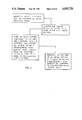
- FIG. 5 is a flow chart of one method of operating a detection apparatus for detecting predetermined indicia in an obstructed field.
- FIG. 6 is a flow chart of another method of operating a detection apparatus for detecting predetermined indicia in an obstructed field.
- FIG. 7 is a flow chart of another method of operating a detection apparatus for detecting predetermined indicia in an obstructed field.
- FIG. 8 is a schematic illustration of a continuous web and various operating stations used in processing thereof the which the control system of the present invention is utilized.
- FIG. 9 is a top view of the web of FIG. 8.
- FIG. 10 is a schematic view of certain signals generated by the control system of FIG. 8.
- FIG. 11 is a schematic diagram of certain hardware utilized by the computer in the control system of FIG. 8.
- FIG. 12 is a flow chart of software decisions in the set up mode.
- FIGS. 13A and 13B are flow diagrams of software decisions used in the run mode.
- FIG. 14 is a flow diagram illustrating data flow in the control system of the present invention.
- FIG. 1 A moving film web 10 having repeating sets of graphics provided on associated repeating length portions 11, 13 etc. of the web comprises a register indicia pattern positioned at the same relative location within each repeat length 11, 13 etc.
- the register indicia pattern comprises a single, transversely extending mark 12 having a dimension measured longitudinally of the web of a predetermined value "a" which may be, for example, one-eighth inch.
- Each repeat length also has a code indicia pattern positioned at the same relative location within each repeat length.
- the code indicia pattern comprises a single, transversely extending mark 14 having a predetermined, longitudinally measured dimension "b" which may be, for example, one-sixteenth inch.
- the register indicia pattern 12 and the code indicia pattern 14 within each repeat length are separated by a predetermined, longitudinally measured distance "c".
- the distance "c" may be, for example, one inch.
- Other indicia 18, such as, for example, display graphics, quality control graphics, and the like, may also be provided in repeating or random positions within each repeat length 11, 13, etc.
- a first indicia sensing means which in the embodiment of FIG. 1 comprises a register photoelectric sensor 20, is positioned at a fixed location relative to the moving film web whereat a relatively narrow width track 22 that is scanned by the photoelectric sensor 20 intersects a register indicia 12 on each succeeding repeat length 11, 13 etc. as the film web 10 progresses in the direction indicated (from left to right on the sheet of drawing).
- the register photoelectric sensor 20 may comprise a conventional photoelectric sensor including a light source 28 positioned below the moving film web 10 for directing a narrow beam of light 29 through the film web to a light sensor 30.
- the light sensor 30 generates a signal based upon the presence or absence of light from the light beam 29 which is periodically obstructed by the printed indicia on the film web 10.
- a time based signal is generated which, when compared with a film velocity based signal, may be used to determine the exact location and longitudinal dimesion of indicia passing through the light beam, i.e., indicia positioned along path 22.
- a film velocity based signal may be generated by a conventional encoder 32 or "rotor-pulsor" of the type described in the Haake et al. Patent Application Ser. No. 441,276 filed Nov. 12, 1982.
- the encoder 32 may be mounted to rollingly contact a roll 34 having a surface speed equal to that of the film web 10.
- Both the encoder 32 speed based signal and the time based signals from the photoelectric sensor 20, 24 are received and processed by a processing means such as a conventional microprocessor 36 of the type described in Haake et al. Patent Application Ser. No. 441,276 filed Nov. 12, 1982. It is an important feature of the present invention that indicia other than the register indicia 12 may be present along path 22 without affecting the accuracy or operation of the apparatus.
- a second indicia sensing means in the embodiment of FIG. 1 comprises a code photoelectric sensor 24 which may be of identical construction to the register photoelectric sensor 20 and which senses all indicia positioned along a longitudinally extending, code sensing track 26 parallel to the register sensing track 22.
- Code photoelectric sensor 24 is positioned so as to intersect each code indicia pattern 14 on the moving film web.
- the two photoelectric sensors 20, 24 comprise an indicia sensing means for sensing the spacial characteristics of indicia lying within a longitudinally extending, indicia sensing path which, in turn, comprises the register sensing track 22 and the code sensing track 26.
- FIG. 5 One method of utilizing the apparatus shown in FIG. 1 to cause exclusive registration of the passage of register indicia patterns such as mark 12 is illustrated in FIG. 5.
- Photoelectric 20 continuously monitors the passage of all indicia along code track 22 providing information regarding the longitudinal dimension of each set of indicia sensed and also the longitudinal spacing between the sensed indicia in a code-track-indicia-detection signal.
- Photoelectric sensor 24 simultaneously monitors the passage of all indicia along code track 26 and provides information regarding the longitudinal dimension and spacing of the indicia in a code-track-indicia-detection signal.
- each of the two indicia indicating signals is compared with a predetermined mathematical model.
- This model may consist, with respect to the register track detection signal, of the criteria that the indicia being examined must have a longitudinal dimension falling within a predetermined value range, e.g., the criteria may be that the indicia must have a dimension less than 1.1a and greater than 0.9a.
- the criteria may be that the indicia must have a dimension less than 1.1b and greater than 0.9b.
- a second set of signals is provided in response to each of these comparisons of the first set of signals with the respective mathematical models.
- the second set of signals generated indicates the relative position of indicia patterns conforming to the register indica model in the case of one signal and to the code indicia model on the case of the other signal.
- the second set of signals i.e., the two pattern detection signals, is then compared.
- code-pattern-detection signal indicating the occurrence of a code pattern and a portion of the register-pattern-detection signal indicating the occurrence of a register pattern both occur within a predetermined time span, i.e., in physical terms, if the code mark 12 and the register mark 14 are detected within a predetermined distance of each other, the relative position of the detected-register-indicia pattern is recorded, i.e., registered for further processing.
- the mark must meet certain predetermined criteria regarding its longitudinal positioning. (In the preceding example, it must have a longitudinal dimension within 10 percent of the value of "a”.)
- the mark must be within a predetermined longitudinal distance from a detected code mark.
- the code mark must have been found to meet certain predetermined characteristics. (In the preceding example, it must have a longitudinally measured dimension within 10 percent of the value "b".)
- a film web 40 having repeat lengths 41, 43 etc. is provided with a register indicia pattern which may be a single mark 42 having a longitudinally measured dimension "a".
- the web is also provided with a code-indicia pattern 44 which, in the illustrations of FIGS. 2 and 3, comprises three bar portions 45, 47, 49 of the letter "B".
- the bars have longitudinally measured dimensions of b 1 , b 2 , b 3 , respectively, and are separated by longitudinally measured distances of d 1 , d 2 , respectively.
- the register indicia pattern 42 and the code indicia pattern 44 are positioned so as to be intersected by a single, narrow-width-scanning track 52 of a photoelectric sensor 50 which may be of an identical construction to photosensor 20 described with reference to FIG. 1a.
- the code indicia pattern and the register indicia pattern are separated by a distance "c".
- a randomly positioned indicia 48 from the surrounding indicia field may lie along path 52 between the register indicia pattern 42 and the code indicia pattern 44.
- a register-indicia-pattern window 54 having a longitudinally measured dimension "x" is provided in a longitudinally bracketing relationship about the register indicia pattern 42 as will be described in further detail hereinafter.
- the register window 54 may begin at a distance "y" from the upstream edge of the code indicia pattern 44.
- the gap between patterns 42, 44 is here designated by the numeral 56.
- the indicia monitoring apparatus of FIG. 2 operates by continuously monitoring a single detection path 52 and generating an indicia detection signal containing information as to the longitudinal dimension and longitudinal spacing of indicia detected by the photoelectric sensor 50.
- the indicia detection signal is compared with a mathematical model of the code indicia pattern 44.
- the mathematical model consists of information including the longitudinal dimensions of each set of indicia sensed and also the distance between indicia sensed.
- the mathematical model could require that the three indicia separated by distances equal to plus or minus 10 percent of d 1 with respect to the first distance and plus or minus d 2 with respect to the second distance be detected and, further, that the dimensions of the three indicia detected lie within the values 0.9b 1 to 1.1b 1 , 0.9b 2 to 1.1b 2 and 0.9b 3 to 1.1b 3 , respectively.
- all indicia within a predetermined window 54 positioned a predetermined distance "y" downstream of the detected-code-indicia pattern are compared with a second mathematical model corresponding to the register indicia pattern.
- this may consist of the single criterion that the longitudinal dimension be within 10 percent of the value "a”. If the indicia sensed within the window 54 conform to this value, they are then registered for further processing.
- a moving film web 70 is provided with a series of register indicia patterns 72 at predetermined positions within repeat lengths 71, 73, 75, etc.
- Each register indicia pattern 72 has an associated code indicia pattern 74 positioned in longitudinally and transversely spaced-apart relationship from the register indicia pattern.
- the register indicia pattern 72 may comprise two marks 72A, 72B, each having a predetermined longitudinal dimension separated by a predetermined longitudinal distance.
- Each of the code indicia patterns may also comprise two marks 74A, 74B having predetermined longitudinal dimensions and spacing.
- the register indicia pattern 72 is separated from the code indicia pattern 74 longitudinally by a predetermined distance.
- a register indicia window 78 brackets the register indicia 72 and is positioned at a predetermined longitudinal distance from the code indicia pattern 74.
- Surrounding field indicia 80 may be positioned within the code sensing track 84 or register sensing track 89 defined by photoelectric code sensor 82 and photoelectric register 86, respectively.
- the sequence of operations leading to registering of indicia pattern 72 may begin with continuously monitoring code track 84 and generating a code-track-indicia-detection signal.
- the code-track-indicia-detection signal is then compared with a model of the code indicia pattern based on criteria of, e.g., the dimensions of marks 74A, 74B, and the spacing therebetween.
- a command signal is generated to activate photosensor 86 at a predetermined longitudinal distance from the point of detection of the code indicia pattern.
- the photosensor 86 monitors only a small length predetermined portion of path 88 before it is switched off providing an indicia detecting signal.
- Indicia detected are compared with a second mathematical model with predetermined criteria based on the characteristics of the of the register indicia, e.g., number of marks, spacing between marks, mark dimensions. If the indicia detected by photoelectric sensor 86 conform to the mathematical model, then the position where this indicia pattern occurred is registered.
- the Indicia Recognition System of the present invention may be used in a cutterline 1010 as illustrated in FIG. 8.
- the cutterline comprises a series of different areas for performing operations on a continuous web of material resulting in the cutting of predetermined portions of the continuous material web 1020 to form a plurality of individual cut blanks 1112.
- the material web 1020 moves through the machine in a longitudinal direction 1019. As illustrated in FIG. 9, the web 1020 comprises a pair of parallel lateral edges 1021, 1022. A repeating pattern of graphics 1023 including repeating marks W, X, Y, Z are printed on the web 1020 and repeat at a predetermined substantial constant distance interval along the web hereinafter referred to as the "repeat length" 1024. Small variations in the repeat length may occur due to tension changes, etc. in the moving web. Within each repeat length 1024 is a design cutting location 1025, 1026, etc. The "design cutting location” refers to the location of the cut which the cutter 1098 will cut in the web if the system is operating correctly.
- the design cutting location thus has a preset relationship with respect to the graphics in any repeat length of web material. It will be appreciated that this design cutting location may vary from the actual cut made in repeat length if the web is not properly longitudinally phased and laterally aligned with the cutter.
- the shape of the design cut is rectangular and comprises lateral edges 1027, 1028 positioned generally parallel the web lateral edges 1021, 1022 and also comprises a leading edge 1029 and a trailing edge 1030 positioned generally perpendicular the lateral edges of the web.
- Each repeat length 1024 comprises the longitudinal dimension 1031 of the design blank pattern i.e.
- the length of the pattern and also comprises the longitudinal dimension 1032 of the portion of the web 1037 positioned between the design cuts 1025, 1026 which may become scrap subsequent to the cutting of the web (depending on the shape of carton).
- the lateral dimension or width of the web 1033 comprises the lateral dimension 1034 of the blank cutting pattern and the lateral dimension 1035, 1036 of the portion of the web 1038, 1039 positioned outwardly of the design cut which will also become a portion of the scrap after the web is cut.
- the first station of the cutterline 1010 is an unwind stand 1012 at which an unwind roll 1014 and a reserve roll 1016 are mounted on a conventional yolk 1018.
- Each of the rolls 1014, 1016 comprises a wound continuous web of material such as paper, plastic film, paper-film composite, or the like.
- a typical roll of material may have a width of 44 inches and a maximum diameter of 80 inches and may weigh on the order of 21/2 tons.
- the material web 1012 is pulled from the unwind roll 1014 until the roll is exhausted.
- the trailing edge of the web from roll 1014 is then spliced to the leading edge of material on the reserve roll 1016 at which point the reserve roll becomes the unwind roll and another roll is mounted on the yolk 1018 in place of roll 1014.
- the continuous web 1012 is drawn from the unwind roll 1014 by a pair of pinch rolls 1042, 1044 located in a decurl unit 1040 which may also be used in the web splicing operation. Subsequent to passing through the pinch rolls 1042, 1044 the web 1012 passes over decurl rolls 1046, 1048 which take out some of the curl which sets into a roll of material over the period in which it is in storage.
- the decurl rolls may also be used for lateral alignment of the moving film web 1020.
- the rolls 1046, 1048 are mounted on a frame which may be tilted from side to side to shift the web laterally as it crosses the rolls to maintain the web in a proper lateral position.
- a web edge sensor assembly 1049 is used to determine the lateral position of an edge portion of the film web and, based upon this determination, provides a signal to a hydraulic drive unit 1041 which tilts the frame supporting rollers 1046, 1048 in response to the signal to maintain the web 1020 in a laterally centered location in decurl unit 1040. Subsequent to passing through the decurl unit 1040 the web may pass into a string insertion unit 1050 in which strings may be glued onto the web to increase web strength.
- the actual assembly for string insertion may be of the type illustrated in U.S. Pat. No. 4,496,417 of Haake et al. which is hereby incorporated by reference.
- the web passes over a series of rolls 1052, 1054, 1056, 1058, 1060 in the string insertion unit.
- the web 1020 passes into a cutter creaser assembly 1070 which comprises a plurality of rolls including idler roll 1072; nip rolls 1074, 1076 driven by motor 1075; and idler roll 1078.
- the web passes over these rolls prior to entering a cutter unit 1090 comprising an upper fixed cutter portion 1092 and a lower reciprocating cutter portion 1094 which is caused to reciprocate at a constant speed by a cutter drive motor 1096.
- Fixed knives 1098 mounted on the lower reciprocating cutter portion 1094 have the same configuration as the design cut 1025, 1026.
- the web passes over a delivery table 1110 where cut blanks 1112, in the shape of design cuts 1025, 1026, etc., formed in the cutting operation are caused to be deposited on the delivery table in stacked relationship.
- the cutter unit 1090 and stacking table 1110 assembly may be of a conventional type well known in the art.
- the cutter unit may be model no. Z714 manufactured by Zerand of New Berlin, Wisc.
- the scrap web 1114 i.e. the web with the blanks 1112 removed therefrom is cut into small pieces and removed at the stripper which is a part of the cutter between 1094 and 1114.
- the scrap web 1114 may be collected for disposal or recycling.
- a central control problem solved by the present invention is the longitudinal phasing of a web 1020 to a cutter 1090 to ensure that the cutter cuts the web precisely at the design cuts 1025, 1026 rather than at some other longitudinal position which is longitudinally misaligned with the graphics 1023 in each repeat length 1024.
- the apparatus for providing longitudinal monitoring and control of the web 1020 will now be described.
- a series of longitudinally spaced-apart laterally extending marks W, X, Y, Z are repeated at intervals along the film web 1020 which define the repeat length 11024.
- the marks are positioned in a predetermined fixed relationship relative the repeating graphics 1025, 1026 on the web 1020 and are also located in generally fixed relationship between the lateral edges 1021, 1022 of the web 1020.
- the marks W, X, Y, Z extend laterally of the web and are generally in longitudinal alignment with respect to the web such that all of the marks will be detected by a single mark detection unit positioned at a fixed location above the web and defining a longitudinally extending mark detection path 1125.
- the unit 1120 may be moved laterally as indicated at 123 to other discrete positions to define a plurality of other mark detection paths such as 1127.
- the photo eye assembly 1120 is positioned between the mark detection string insertion assembly 1050 and the cutter assembly 1070 at a location 1121 a predetermined known distance of web travel from the cutter unit 1090.
- a strobe unit 1122 is positioned in this same general area to illuminate a relatively small portion of the web which includes the area of mark detection 1121 of the photo eye assembly 1120 or may be positioned an integer number of repeat lengths away from 1121 e.g. two repeat lengths upstream or downstream.
- An encoder unit 1124 which puts out a predetermined number of electronic pulses per revolution of an associated roller is mounted on roller 1072 immediately downstream of photo eye assembly 1120.
- the roller 1072 engages the web 1020 passing thereover in non-slipping contact and thus the number of pulses from encoder 1124 during any particular time interval is linearly proportional to the distance that web 1020 has travelled during that time interval.
- a computer 1100 (which may include a conventional microcomputer or minicomputer with appropriate control software and electronics) receives signals from the encoder, photo eye, and drive motors 1075 and 1096.
- An input terminal means such as keyboard 1130 is provided to enable operator input of certain values particular to a web being run and also to manipulate the strobe 1122 as described below.
- each of the longitudinally spaced-apart pre-printed marks W, X, Y, Z are located at a fixed longitudinal position with respect to an associated design cut e.g. 1025 then the distance of that design cut relative the cutter knives 1098 may be precisely determined if the distance of any mark W, X, Y, Z from the mark detection point 1121 beneath the photo eye 1120 is known. For example if mark W is located at the leading edge 1029 of each design cut 1025, 1026, etc. and if the mark detection point 1121 is located 3 repeat lengths from the leading edge of knives 1098 (corresponding to design cut leading edge 1029) then it may be determined that the design cut 1025 is 3 repeat lengths from the cutter. If the distance of a design cut e.g.
- the web may be brought back into phase with the cutter (assuming that both the cutter and the web speed are proper for the repeat length being cut) by either phasing the cutter to the web (by stopping and restarting it properly) or by phasing the web to the cutter (by speeding up or slowing down the web for a short period of time and then returning to normal line speed).
- One operation performed by the control system of the present invention is the selection and recognition of a register mark within each repeat length 1024 that enables an associated computer 1100 to determine the relative position of each incoming set of repeating graphics and associated design cut with respect to the cutter 1098.
- a computer 100 in accordance with this determination of relative position between the incoming graphics pattern and the cutter 1090 and in accordance with the phase of the cutter controls the speed of the motor 1075 which drives nip rolls 1074, 1076 to phase the graphics on the web to the cutter.
- the phasing of a repeating patterns of graphics etc. on a moving web to a cutter or other device performing periodic operations on the web is described in U.S. Pat. No. 4,549,917 of James W.
- the computer is initially updated with certain information supplied by a human or by the system software data base operator. Included in this information is the repeat length of the web 1020 graphics; typically a value between 10 inches and 40 inches.
- the image recognition system is placed in a start up mode in which an encoder 1124 pulse signal 1140 and a photo eye 1120 mark detection pulses signal 1142, FIG. 10, are input to the computer 1100.
- the encoder 1124 may typically have a pulse frequency on the order of 500 or 1000 pulses per inch of web travel.
- the pulses produced by a photo eye 1120 may be square wave pulses produced by sensing light intensities above and below a preset value. In the illustrated example of FIG. 10 the upper portion of the signal indicates the presence of a dark area on the web.
- the computer functions described herein are typically set to be triggered by the leading edge of a dark area indicating pulse but might also be set to be triggered by the trailing edge.
- the computer randomly chooses a mark such as W as shown in FIG. 10. Since the computer "knows" the repeat length of the web 1020, it may compute when the mark W will be repeated by counting the number of encoder pulses in signal 1140 which occur after sensing the leading edge of mark W in pulse signal 1142. When the number of encoder pulses counted is sufficiently close to the total number of encoder pulses which would be generated in one repeat length, e.g. when the counted pulses are 97% of this total repeat length number, a register pulse generating task of the computer starts "looking" for a mark pulse from signal 1142 and generates a pulse signal e.g.
- the strobe is illuminated at each register pulse W 1 and thus illuminates mark W at the time it passes beneath photo eye 1120.
- the human operator can see which mark the computer has chosen for a register mark.
- the operator may decide to use this register mark or may select a new register mark by sending a "change mark" signal to the computer.
- the computer upon receiving a "change mark” signal skips to the next succeeding mark, e.g. mark X, and again repeats the above described operation to generate a new register pulse signal 1144 and associated strobe coinciding with the passage of mark X. This mark skipping process may be repeated until the operator has chosen the desired mark for use in register signal 1144.
- the computer Each time a register mark is selected, either by the computer or by the human operator, the computer generates a "profile" of the register mark by which it may verify that it is indeed using the selected register mark during subsequent systems operation in the "running mode.”
- the computer also "profiles" each of the other detected marks in the repeat length in order that it may, when operating in the running mode, "recognize” which mark it is erroneously using as the register mark if it has previously determined that the correct mark is not actually being used.
- each mark W, X, Y, Z is positioned, in any repeat length, at a fixed set of distances from all other marks in that repeat length.
- a set of data collected over one repeat length of the web which includes the distance values between all individual marks in the web--d 1 1 , d 2 1 , d 3 1 , d 4 1 in FIG. 10--will be referred to as the "repeat length scan image" or simply "scan image” hereinafter.
- the leading edge of the mark being profiled is selected as the beginning of a repeat length distance over which the mark is profiled and the distances from the leading edge of the mark being profiled to the leading edge of each other mark in that repeat length is calculated and stored in memory.
- the mark detection pulse signal 1142 might change because the mark detection path associated with photo eye 1120 would change.
- mark Y would not be detected and the pulse signal 1142 would be as shown without the phantom lines-indicating no pulse for mark Y.
- the mark images taken by profiling each mark in mark detection path 1127 would be different from the profile of identical marks taken in path 125.
- the mark images of the marks when profiled in path 127 would be computed from scan image d 1 2 ; d 2 2 ; d 3 2 and are as follows:
- a mark may be "recognized" by the computer when the web is shifted slightly laterally from a centered position it may be desirable to provide several profiles of a mark which is selected as the register mark, in laterally offset detection paths. For example in addition to the mark profiles taken when photo eye 1120 is positioned in path 1125 it may be desirable to take profiles, say every 0.050 inches up to a distance spaced 1/2 in. laterally to each side of the control path 1125 by incrementally shifting photo eye 1120 laterally along lateral path 1123 and taking mark profiles at each incremental location. Thus, in this example, twenty one mark images would be generated and stored in memory for the register mark-one image for path 1125 and twenty images each for the paths (only 1127 shown) on either side of path 1125.
- the mark image of a register mark as distinguished from the other marks in a repeat length will be referred to as the "reference image.”
- the generation and use of information from these laterally offset mark detection paths will be referred to herein generally as “two dimensional image recognition.”
- Use of reference images from only a single path will be referred to generally as “single image recognition.”
- the computer 1100 is placed in a "running mode" in which it continuously monitors the passage of the mark which has been selected as the register mark.
- both photo eye pulse signal 1142 and the register mark pulse signal 1144 are generated in the same manner as in the start up mode.
- the register pulse signal 1144 is used during the running mode to continuously inform the computer of the phase position of the web 1020 graphics 1023 and associated design cuts 1025, 1026, etc. with respect to the cutter 1090. This information is used by the computer to generate a control signal to pinch roll motor 1075 etc. to periodically adjust the speed of the web 1020 to maintain proper phasing between the web and cutter.
- An image recognition software task of the computer 100 is provided to determine when a mark which is used to generate register pulse signal 1144 is incorrect. This task, upon making such a determination subsequently "recognizes" which mark is then being used to generate the register pulse signal and corrects the computer's register mark data such that it thereafter uses the new register mark in making its cutter phasing determination.
- the image recognition task operates by continuously taking "scan images" of each incoming repeat length and computing a mark image for the mark in the repeat length that is actually "in sync" with the computer i.e. the mark corresponding to pulse signal 1144. After such a mark image is taken it is compared to the stored reference image of the mark which the computer assumes to be the register mark. If the mark image matches the reference image closely enough no changes are made. However in single dimension image recognition if the mark image does not match the reference image of the assumed register mark then the computer will compare the in sync mark image to the reference image of each of the other marks in the repeat length scan image.
- the computer chooses the mark in the repeat length whose reference image most closely matches the in sync mark image and chooses that mark as the "correct" register mark.
- the computer thereafter changes the data used for cutter phasing to replace the old register mark with newly chosen mark.
- two dimensional image recognition essentially the same procedure is used to monitor and correct the register mark choice that is used by the computer to control web phasing with the cutter.
- two dimensional image recognition also takes into account that none of the mark images may match a reference image due to lateral shifting of the web.
- That additional process is to compare the in sync mark image to each of the other reference images (from laterally displaced paths) of the assumed register mark to see if there is a match. If there is, then the matching reference image of the assumed register mark replaces the old reference image of the assumed register mark and the sync pulse hardware does not reset.
- the in sync mark image is compared with all of the different reference images (from laterally displaced paths) of all of the other marks, and if there is a match, the corresponding mark is chosen as the new register mark and the sync pulse hardware is resynchronized to the newly selected mark. If there is not a match, then the process is repeated in the next repeat length.
- comparing a mark image to the reference image the length values in the mark image are compared one at a time to all of the length values in the reference image.
- the number of matches (within a selected tolerance) between the mark image distance values and the reference image distance values are then counted.
- a determination that a mark image "matches" a reference image is based on the number of matches between the distance values of the two images as compared to the total number of possible matches. For example in a pair of images each having 20 marks in a repeat length, 15 distance component matches would probably be treated as a "match" of images. With only 4 marks in a repeat length a match of only one distance value between images might be too low for a "match" of the images.
- a "confidence number” may be used to make the match or no match decision based upon the confidence number being above or below a preset value.
- W 1 500 is compared to 498, 1210, 2000, 2210, and 2200--this is a match because 500 is within 3 of 498, thus 1 distance match is recorded.
- W 2 1210 is compared to 498, 1210, 1996, 2210, and 2211--1210 matches 1210 and thus another distance match is recorded.
- W 3 1996 is compared to 498, 1210, 2000, 2210, and 2200--no distance match.
- W 4 2211 is compared to 498, 1210, 2000, 2210 and 2200--a match.
- the total image match number is 3 out of a possible 4 for a confidence number of 78.
- An advantage of using a confidence number in determining an image match as opposed to requiring a 100% match of distances in the two images is that it accounts for situations such as in the above example when a random mark, caused by say a defect on the web, appears in a scan image or when one or more marks which previously occurred fail to appear because of lateral web shifting or changing ambient light. In such situations the distance values to the other marks in the repeat length from the mark whose mark image is being taken are not caused to vary by the randomly occurring marks and thus the mark image and the reference image may properly be determined to match even though some of the mark image distances differ from the reference image distances.
- a pulse signal 1142 which contains a pulse corresponding to each mark which is sensed by the photo eye 1120 is input to the hardware windowing circuitry as indicated at 1150, FIG. 11.
- This pulse is also received by hardware which will be referred to hereinafter as pulse shadow hardware.
- the purpose of the pulse shadow hardware is to enable an associated counter to count and code pulses and thus measure the distance between marks. In performing this function it excludes mark pulses which occur too close to a previous mark. A distance that is "too close" is operator selectable and may be on the order of 1/2 inch.
- This shadow windowing hardware comprises a NAND gate 1152; an inverter 154; and a JK flip-flop 1156. All these components are conventional off the shelf components well-known in the art.
- a counter 1160 which receives a gate input at 1162 from the shadow hardware and encoder input 1164 corresponding to encoder pulse signal 1140 and which provides an output 1166 which represents the timing of the shadow pulse. It occurs the pre-set distance, e.g., 1/2 inch, after the gate pulse received. This pulse is output to the JK flip-flop 1156. Another output of the JK flip-flop 1156 which occurs simultaneously with gate signal 1162 to the counter is an inverted signal 1170 which is received by the computer and used as an interrupt to cause the computer to read the value of counter 1160.
- the pulse shadow hardware in combination with counter 1160 and the interrupt controller 1172 and the computer central processing unit is used to measure the distances between individual marks sensed by the photo eye 1120.
- the in sync pulse hardware circuitry comprises a NAND gate 1180, an inverter 1182 a JK flip-flop 1184 associated with a second counter 1186.
- the counter 186 receives a gate pulse from the JK flip-flop at 1188, an encoder signal 1140 from the encoder at 1190 and outputs the signal 1192 to the CPU and a second signal 1194 to the JK flip-flop.
- the function of this hardware circuitry is to generate a measurement from one in sync mark to the next in sync mark and to identify to the computer which mark is in sync.
- the gate output 1188 from flip-flop 1184 may also be used to operate a strobe light for illuminating the mark which is in sync in a manner which is conventional and well-known in the art.
- One dimensional image recognition is the basic image recognition process by which computer software determines if the sync pulse hardware is in sync with the correct mark. If it is found not to be in sync, single dimension image recognition modifies the programmable counter to correct the synchronization. Single dimension image recognition will be referred to as SIDREC hereafter.
- SCAN IMAGE this is a collection of measurements of the distances between the marks in the current image. These values are measured by a second programmable counter, not the sync pulse hardware. It is an ordered list in which the first value (SCAN IMAGE[1]) is the distance from the mark which is in sync at the time and the next mark in line. The last value (SCAN IMAGE[X]), if there are X marks in the image, is the distance from the mark prior to the synced mark to the synced mark. The total of these values is one measurement of repeat length. SCAN IMAGE corresponds generally to distance measurements such as: d 1 1 ; d 2 1 ; d 3 1 ; d 4 1 shown in FIG. 10.
- REF ACCUM LIST this is a collection of measurements from the selected register mark to every mark in the image. It is an ordered list in which REF ACCUM LIST(1) is the distance from the selected register mark to next mark in line.
- REF ACCUM LIST(X) if there are X marks in the image, is the distance from the selected register mark to the next occurrence of the selected register mark or one repeat length. This is not a current image but the reference image which was selected initially at setup time by the operator and possibly refreshed later by the computer. In the example of FIG. 10, REF ACCUM LIST would include W 1 1 , W 2 1 , W 3 1 , W 4 1 ; X 1 1 1 , X 2 1 , X 3 1 , X 4 1 , etc.
- IMAGE CONFIDENCE this is an integer which is equal to 100 if the scan image is an exact match to the reference image. Points are subtracted from this if either there are extra marks in the scan image or if some of the reference image marks are not matched by marks in the scan image. The number of points subtracted is scaled to match the image. That is, if one mark is missing from a 10 mark image confidence, is lowered only a little. If one mark is missing from a 3 mark image, confidence is destroyed. Note that confidence may be 100 even if the image is out of sync. Confidence is a measurement of the knowledge of the image and the knowledge of the location of the register mark.
- REG MARK OK this is a flag which equals 1 if the image is believed to be in sync (irregardless of confidence) and a 0 if not.
- BEST MATCH COUNT when the set of mark images for one scan image is tested against the reference image, each mark in the image is momentarily assumed to be the selected register mark. Each mark image is tested and the number of matches is counted. The highest number found is the BEST MATCH COUNT. The mark which produces the BEST MATCH COUNT is the register mark.
- SCALE ARRAY each time a scan image is taken, the values in the image are adjusted (scaled) to match those that would occur if the image were exactly the correct repeat length. This is necessary because the variation in repeat length which occurs constantly with composite would make the comparison of the reference image which may have been taken on an extra long image, with a scan image which on a particular scan may be extra short, very sloppy. A very large tolerance on individual marks would be required if two such images were to match.
- TEST ASSUME REG MARK this procedure counts the number of matching marks between a single version of the scan image and the reference image. A mark matches if the distance from the assumed register mark to this mark matches any value in the REF ACCUM LIST. The tolerance on the match is selectable e.g. plus or minus 0.050 inches. For each scan image this routine is called as many times as there are marks in that image. It is called one time for each mark image.
- FIND REG MARK also contains the following steps:
- SHIFT MARK this step is used only in setup mode to select a new register mark. It causes the sync to skip to the next mark when the identify mark button is pressed. Or if pressed multiple times, to skip that many marks.
- REFRESH REF this routine is used to install the current image in the REF ACCUM LIST in two different modes.
- setup mode constantly copies the current image to the REF ACCUM LIST. It assumes that the image is in sync with the desired mark.
- run mode a refresh occurs only if the image in in sync and the confidence is higher than the selected limit. This is done to allow SIDREC to maintain a good image even if there are small variances in the image from time to time. These are common and are caused by sidelay motion of the web and photo eye sensitivity variations.
- SCAN MODE this mode is requested by the operator at a point in the setup procedure. It is done after the "Setup Mode" when the operator selects the mark. SCAN MODE drives the photo eye assembly to the side a selected number of times. In each position it takes and records a reference image. The photo eye assembly returns to the center of the Reg Mark and then drives to the other side to take the other half of the possible images. The operator may select the number of images to be taken and the distance between each image. A complete set of reference images is kept for future reference by the SEARCH MODE.
- SEARCH MODE in the event that SIDREC believes the sync pulse hardware is out of sync with the correct mark but cannot resync due to low IMAGE CONFIDENCE, the search mode is called. A copy of the current image is made and then tested against the entire set of reference images. The IMAGE CONFIDENCE is measured for every reference image. The best image is returned as a recommendation to SIDREC. If the confidence is higher than a set limit and SIDREC is still in need of a new reference image, then the returned image is copied into the REF ACCUM LIST. SIDREC then goes on with a new REF ACCUM LIST (new reference image) and uses the current SCAN IMAGE (which may have changed since SEARCH MODE was called) and attempts a resync if it can.
- FIG. 14 A data flow chart which shows memory storage, software modules and the paths of data flow in computer 1100 is illustrated in FIG. 14.
- a word (2 byte) value equal to the number of encoder pulses from 1 sync pulse to the next, it only occurs on the sync pulse and therefore indicate which of the pulse shadow marks is in sync.
- a word (2 byte) value equal to the number of encoder pulses from 1 mark to another.
- F. Match count a byte which is the number of in tolerance matches between a single mark image and the reference image.
- I An array of arrays of words. Each array is a reference ACCUM LIST based on the register mark but in a different lateral position.
- the first decision to be made is whether the mark selected by the sync pulse hardware is the one desired by an operator.
- the decision to use the mark selected by the computer or to select a new mark is indicated at I.
- the operator sends a signal to the computer whereby the mark selected by the computer is shifted one position as indicated at II.
- refresh reference refers to the operation of computing a reference image from the current scan image and copying that information into the reference image memory location in the computer.
- the next step, IV, indicated as wait for next scan image indicates that the computer waits for the next scan image to occur and then accumulates scan image data consisting of the distance values between the various marks in the scan image.
- V indicates that this data from the scan image is scaled to the specification for correct repeat length. This function is necessary to correct situations in which the web, especially a plastic web, may stretch or shrink from a preset specified repeat length.
- VI indicates that the mark selection process has been completed. This is a timed function based on shift command. If no shift command has occurred within fifteen seconds then the computer moves to the next function indicated at VII.
- the computer waits for the next scan image and collects the data values from the scan image when it occurs.
- the data from the scan image is then scaled in the same manner as described above in the setup mode.
- the next function performed is the selection of one mark from all of the marks in the scan image. That mark is assumed to be the register mark and as indicated at XII the mark image of the assumed register mark is tested against the current reference mark image and a match count of the matching data values of the two images is calculated.
- This match count is recorded if it is the best match count of any thus far tested with respect to a particular scan image as indicated at step XIII.
- the computer decides whether or not all of the marks in the scan image have been tested against the current register mark. If they have not, then the mark in the scan image is tested and this process continues until all marks have been tested. After all marks have been tested the process moves to XV. At XV the confidence number for the mark having the best match count is calculated. As indicated at XVI a decision is then made based upon whether the mark with the best match count is in synchronization with the photo eye 1120 i.e. whether that mark is the mark which corresponds to the pulse of reference signal 1144.
- step XII the decision path to operation XVIII is indicated where the test results are indicated to be alright and the test value flag is set to one. If the mark is now in sync then the test flag value is set to 0 as indicated at box XVII. The next decision made as indicated at XIX is whether the mark is not in sync and whether the image confidence is above a predetermined value. If both of these statements are true then the image is resynced as indicated at box XX. If either or both of these statements is incorrect then the process moves to the decision indicated at XXI. If the assumed register mark is not in sync and if the image confidence is less than the set point then the decision process moves to step XXII.
- step IXVII the computer checks to see if the search mode is in progress. If it is then the decision process returns to step IX and waits for information from the next repeat length. If the search mode is not in progress then the next decision as indicated at XXIII is whether the search mode is completed and waiting. If it is not completed and waiting then the search mode is called as indicated at XIV and thereafter the decision process returns to step IX. If the search mode is completed and waiting then the decision process moves to decision XXV to determine whether the confidence number of the selected mark is greater than the predetermined set point. If it is not then the decision process returns to step IX.
- step XXI if that decision is no, then the next decision to be made as indicated at step XXVII is whether the register mark is in sync and also if the image confidence is above the predetermined set point. If both of these conditions are not met then the decision process returns to IX. If both of these conditions are met then the decision making process goes to step XXVIII indicating that if the current reference image is not perfect then new data for the mark used as the current reference image is substituted for the data presently used as the reference image for that mark. Thereafter the system again returns to step IX.
Landscapes
- Engineering & Computer Science (AREA)
- Physics & Mathematics (AREA)
- Artificial Intelligence (AREA)
- Computer Vision & Pattern Recognition (AREA)
- General Physics & Mathematics (AREA)
- Theoretical Computer Science (AREA)
- Health & Medical Sciences (AREA)
- Electromagnetism (AREA)
- General Health & Medical Sciences (AREA)
- Toxicology (AREA)
- Measuring Pulse, Heart Rate, Blood Pressure Or Blood Flow (AREA)
- Controlling Rewinding, Feeding, Winding, Or Abnormalities Of Webs (AREA)
- Radar Systems Or Details Thereof (AREA)
- Paper (AREA)
- Fire-Detection Mechanisms (AREA)
Abstract
Description
Claims (22)
Priority Applications (9)
| Application Number | Priority Date | Filing Date | Title |
|---|---|---|---|
| US06/838,383 US4835720A (en) | 1986-03-11 | 1986-03-11 | Obstructed-field-indicia-sensing device |
| ZA871533A ZA871533B (en) | 1986-03-11 | 1987-03-03 | Obstructed-field-indicia-sensing device |
| AU69695/87A AU586539B2 (en) | 1986-03-11 | 1987-03-04 | Obstructed field indicia sensing device |
| EP87103409A EP0237022B1 (en) | 1986-03-11 | 1987-03-10 | Obstructed field indicia sensing device |
| CA000531614A CA1293802C (en) | 1986-03-11 | 1987-03-10 | Obstructed field indicia sensing device |
| AT87103409T ATE98793T1 (en) | 1986-03-11 | 1987-03-10 | OBSTACLE DATA FIELD SENSING DEVICE. |
| DE3788446T DE3788446T2 (en) | 1986-03-11 | 1987-03-10 | Field sensing device for hindering data. |
| JP62056410A JPS62295863A (en) | 1986-03-11 | 1987-03-11 | Method for monitoring the topological relationship of a material web with respect to a selected reference point and apparatus for monitoring the passage of a mark on a moving material web |
| BR8701116A BR8701116A (en) | 1986-03-11 | 1987-03-11 | APPLIANCE FOR MONITORING THE PASSAGE OF CERTAIN REPEATING MARKS ON A CONTINUOUS LEAF OF ADVANCED MATERIAL AND PROCESS TO MONITOR THE STAGE ADJUSTMENT RELATIONSHIP OF A CONTINUOUS MATERIAL LEAF IN ADVANCED |
Applications Claiming Priority (1)
| Application Number | Priority Date | Filing Date | Title |
|---|---|---|---|
| US06/838,383 US4835720A (en) | 1986-03-11 | 1986-03-11 | Obstructed-field-indicia-sensing device |
Publications (1)
| Publication Number | Publication Date |
|---|---|
| US4835720A true US4835720A (en) | 1989-05-30 |
Family
ID=25276981
Family Applications (1)
| Application Number | Title | Priority Date | Filing Date |
|---|---|---|---|
| US06/838,383 Expired - Lifetime US4835720A (en) | 1986-03-11 | 1986-03-11 | Obstructed-field-indicia-sensing device |
Country Status (9)
| Country | Link |
|---|---|
| US (1) | US4835720A (en) |
| EP (1) | EP0237022B1 (en) |
| JP (1) | JPS62295863A (en) |
| AT (1) | ATE98793T1 (en) |
| AU (1) | AU586539B2 (en) |
| BR (1) | BR8701116A (en) |
| CA (1) | CA1293802C (en) |
| DE (1) | DE3788446T2 (en) |
| ZA (1) | ZA871533B (en) |
Cited By (15)
| Publication number | Priority date | Publication date | Assignee | Title |
|---|---|---|---|---|
| US5060281A (en) * | 1987-10-15 | 1991-10-22 | Futec, Inc. | Method and apparatus for detecting disparity of cyclic length of printed patterns |
| US5365847A (en) * | 1993-09-22 | 1994-11-22 | Rockwell International Corporation | Control system for a printing press |
| US5400258A (en) * | 1993-09-03 | 1995-03-21 | Measurex Corporation | Automatic cross-directional control zone alignment for sheetmaking systems |
| US5628574A (en) * | 1996-03-19 | 1997-05-13 | Roll Systems, Inc. | Web error recovery divert system |
| WO1999024263A1 (en) * | 1997-11-10 | 1999-05-20 | Oce Printing Systems Gmbh | Method and device for conveying a pre-printed striplike recording medium in a printing device |
| US6328832B1 (en) | 1998-06-26 | 2001-12-11 | S-Con, Inc. | Labeling apparatus with web registration, web cutting and carrier mechanisms, and methods thereof |
| US6450230B1 (en) | 1999-06-24 | 2002-09-17 | S-Con, Inc. | Labeling apparatus and methods thereof |
| US6452679B1 (en) | 1999-12-29 | 2002-09-17 | Kimberly-Clark Worldwide, Inc. | Method and apparatus for controlling the manufacturing quality of a moving web |
| US6550512B2 (en) * | 2001-01-23 | 2003-04-22 | Yang Sheng-Hui | Labeling machine capable of preventing erroneous attachment of labels on containers |
| US20030169454A1 (en) * | 2000-05-25 | 2003-09-11 | Lars Rodman | Method and device for length measurement of packaging webs |
| US20040042651A1 (en) * | 2002-08-30 | 2004-03-04 | Lockheed Martin Corporation | Modular classification architecture for a pattern recognition application |
| US20080258453A1 (en) * | 2007-04-23 | 2008-10-23 | Adrian Helmut Alt-Steiner | Page of a printed product having a plurality of information fields arranged in different print columns, and longitudinal perforation device for producing the page |
| US20120198332A1 (en) * | 2009-10-06 | 2012-08-02 | Masayuki Shimada | Electronic document processing device, electronic document display device, electronic document processing method, electronic document processing program, and storage medium |
| US11314971B2 (en) | 2017-09-27 | 2022-04-26 | 3M Innovative Properties Company | Personal protective equipment management system using optical patterns for equipment and safety monitoring |
| US11373076B2 (en) | 2017-02-20 | 2022-06-28 | 3M Innovative Properties Company | Optical articles and systems interacting with the same |
Families Citing this family (3)
| Publication number | Priority date | Publication date | Assignee | Title |
|---|---|---|---|---|
| US4781317A (en) * | 1986-08-29 | 1988-11-01 | Adolph Coors Company | Phasing control system for web having variable repeat length portions |
| US5000725A (en) * | 1988-11-07 | 1991-03-19 | Fmc Corporation | Bi-directional registration of servo indexed webs |
| DE19838545A1 (en) | 1998-08-25 | 2000-03-02 | Focke & Co | Method and device for recognizing print marks |
Citations (25)
| Publication number | Priority date | Publication date | Assignee | Title |
|---|---|---|---|---|
| DE1413857A1 (en) * | 1960-10-22 | 1968-10-10 | Inventio Ag | Method and device for reading out certain marks from an overall print image when processing railway goods |
| US3439176A (en) * | 1965-02-25 | 1969-04-15 | Crosfield Electronics Ltd | Photoelectric register control of presses for printing,folding or cutting webs |
| DE2053283A1 (en) * | 1970-10-30 | 1972-05-04 | Siemens Ag | Device for photoelectric scanning of register marks on a printing web |
| US3783293A (en) * | 1969-04-17 | 1974-01-01 | Crosfield Electronics Ltd | Register control systems |
| AU8111275A (en) * | 1975-05-13 | 1976-11-18 | Rca Corporation | Article identification apparatus |
| US4066015A (en) * | 1975-07-11 | 1978-01-03 | Uarco Incorporated | Stationery printing apparatus for continuous business forms stationery assemblies |
| DE2731914A1 (en) * | 1977-07-14 | 1979-01-25 | Sick Optik Elektronik Erwin | Multi-colour printer monitoring system - has optical searching heads to scan datum lines with misalignment transmitted to control system |
| US4143566A (en) * | 1978-01-09 | 1979-03-13 | Pako Corporation | Semiautomatic strip feed control |
| US4170883A (en) * | 1976-05-17 | 1979-10-16 | Milliken Research Corporation | Printing of pattern designs with computer controlled pattern dyeing device |
| US4248655A (en) * | 1979-06-01 | 1981-02-03 | The Meyercord Co. | Position control system for a moving web |
| US4254173A (en) * | 1978-11-20 | 1981-03-03 | Coors Container Company | Composite material for secondary container packaging |
| US4364502A (en) * | 1980-06-23 | 1982-12-21 | Milliken Research Corporation | Line sensor arrangement |
| US4366372A (en) * | 1979-06-01 | 1982-12-28 | Innovative Design, Inc. | Apparatus and method for counting repetitive marks on a running web |
| US4482972A (en) * | 1981-06-25 | 1984-11-13 | Lewis Clarence A | Distance sensing apparatus and method |
| US4485982A (en) * | 1982-11-24 | 1984-12-04 | Xerox Corporation | Web tracking system |
| US4495583A (en) * | 1982-06-04 | 1985-01-22 | Harris Graphics Corporation | Apparatus and method for encoding positions of web press machines |
| US4496417A (en) * | 1982-11-12 | 1985-01-29 | Adolph Coors Company | Control stretch laminating device |
| US4542893A (en) * | 1984-11-14 | 1985-09-24 | Bell & Howell Company | Overlapping document strip conveying method and apparatus |
| US4549917A (en) * | 1983-02-01 | 1985-10-29 | Adolph Coors Company | Die cut window laminating device |
| US4572752A (en) * | 1982-11-12 | 1986-02-25 | Adolph Coors Company | Control stretch laminating device |
| US4617080A (en) * | 1983-12-09 | 1986-10-14 | Sony Corporation | Film laminating apparatus |
| US4644584A (en) * | 1982-05-19 | 1987-02-17 | Sumio Nagashima | Pattern position detecting apparatus |
| US4717059A (en) * | 1983-02-28 | 1988-01-05 | Kabushiki Kaisha Sato | Label positioning method and label feeder for continuous label printer |
| US4719575A (en) * | 1984-09-14 | 1988-01-12 | Web Printing Control Co., Inc. | Method and apparatus for controlling web handling machinery |
| US4737904A (en) * | 1986-04-28 | 1988-04-12 | Nikki Denso Co., Ltd. | Standard-length positioning apparatus |
Family Cites Families (5)
| Publication number | Priority date | Publication date | Assignee | Title |
|---|---|---|---|---|
| US3774016A (en) * | 1971-10-04 | 1973-11-20 | Sun Chemical Corp | Control of process according to registration indicia on material being processed |
| US4366753A (en) * | 1980-04-11 | 1983-01-04 | Baldwin Korthe Web Controls, Inc. | Circumferential registration control system |
| JPS5757158A (en) * | 1980-07-07 | 1982-04-06 | Ootomeidetsudo Paakeejingu Sys | Positioning for continuous web |
| US4384500A (en) * | 1980-11-20 | 1983-05-24 | Owens-Illinois, Inc. | Registration control for a label cutoff apparatus |
| DD200268A1 (en) * | 1981-09-22 | 1983-04-06 | Klaus Goerner | METHOD AND DEVICE FOR DETECTING AND EVALUATING REGISTER MARKS ON A PRESSURE TRACK |
-
1986
- 1986-03-11 US US06/838,383 patent/US4835720A/en not_active Expired - Lifetime
-
1987
- 1987-03-03 ZA ZA871533A patent/ZA871533B/en unknown
- 1987-03-04 AU AU69695/87A patent/AU586539B2/en not_active Ceased
- 1987-03-10 CA CA000531614A patent/CA1293802C/en not_active Expired - Lifetime
- 1987-03-10 AT AT87103409T patent/ATE98793T1/en not_active IP Right Cessation
- 1987-03-10 DE DE3788446T patent/DE3788446T2/en not_active Expired - Fee Related
- 1987-03-10 EP EP87103409A patent/EP0237022B1/en not_active Expired - Lifetime
- 1987-03-11 JP JP62056410A patent/JPS62295863A/en active Pending
- 1987-03-11 BR BR8701116A patent/BR8701116A/en unknown
Patent Citations (25)
| Publication number | Priority date | Publication date | Assignee | Title |
|---|---|---|---|---|
| DE1413857A1 (en) * | 1960-10-22 | 1968-10-10 | Inventio Ag | Method and device for reading out certain marks from an overall print image when processing railway goods |
| US3439176A (en) * | 1965-02-25 | 1969-04-15 | Crosfield Electronics Ltd | Photoelectric register control of presses for printing,folding or cutting webs |
| US3783293A (en) * | 1969-04-17 | 1974-01-01 | Crosfield Electronics Ltd | Register control systems |
| DE2053283A1 (en) * | 1970-10-30 | 1972-05-04 | Siemens Ag | Device for photoelectric scanning of register marks on a printing web |
| AU8111275A (en) * | 1975-05-13 | 1976-11-18 | Rca Corporation | Article identification apparatus |
| US4066015A (en) * | 1975-07-11 | 1978-01-03 | Uarco Incorporated | Stationery printing apparatus for continuous business forms stationery assemblies |
| US4170883A (en) * | 1976-05-17 | 1979-10-16 | Milliken Research Corporation | Printing of pattern designs with computer controlled pattern dyeing device |
| DE2731914A1 (en) * | 1977-07-14 | 1979-01-25 | Sick Optik Elektronik Erwin | Multi-colour printer monitoring system - has optical searching heads to scan datum lines with misalignment transmitted to control system |
| US4143566A (en) * | 1978-01-09 | 1979-03-13 | Pako Corporation | Semiautomatic strip feed control |
| US4254173A (en) * | 1978-11-20 | 1981-03-03 | Coors Container Company | Composite material for secondary container packaging |
| US4366372A (en) * | 1979-06-01 | 1982-12-28 | Innovative Design, Inc. | Apparatus and method for counting repetitive marks on a running web |
| US4248655A (en) * | 1979-06-01 | 1981-02-03 | The Meyercord Co. | Position control system for a moving web |
| US4364502A (en) * | 1980-06-23 | 1982-12-21 | Milliken Research Corporation | Line sensor arrangement |
| US4482972A (en) * | 1981-06-25 | 1984-11-13 | Lewis Clarence A | Distance sensing apparatus and method |
| US4644584A (en) * | 1982-05-19 | 1987-02-17 | Sumio Nagashima | Pattern position detecting apparatus |
| US4495583A (en) * | 1982-06-04 | 1985-01-22 | Harris Graphics Corporation | Apparatus and method for encoding positions of web press machines |
| US4496417A (en) * | 1982-11-12 | 1985-01-29 | Adolph Coors Company | Control stretch laminating device |
| US4572752A (en) * | 1982-11-12 | 1986-02-25 | Adolph Coors Company | Control stretch laminating device |
| US4485982A (en) * | 1982-11-24 | 1984-12-04 | Xerox Corporation | Web tracking system |
| US4549917A (en) * | 1983-02-01 | 1985-10-29 | Adolph Coors Company | Die cut window laminating device |
| US4717059A (en) * | 1983-02-28 | 1988-01-05 | Kabushiki Kaisha Sato | Label positioning method and label feeder for continuous label printer |
| US4617080A (en) * | 1983-12-09 | 1986-10-14 | Sony Corporation | Film laminating apparatus |
| US4719575A (en) * | 1984-09-14 | 1988-01-12 | Web Printing Control Co., Inc. | Method and apparatus for controlling web handling machinery |
| US4542893A (en) * | 1984-11-14 | 1985-09-24 | Bell & Howell Company | Overlapping document strip conveying method and apparatus |
| US4737904A (en) * | 1986-04-28 | 1988-04-12 | Nikki Denso Co., Ltd. | Standard-length positioning apparatus |
Non-Patent Citations (1)
| Title |
|---|
| English translations of these references are also enclosed, This reference corresponds to French Patent Document No. 77 38907. * |
Cited By (23)
| Publication number | Priority date | Publication date | Assignee | Title |
|---|---|---|---|---|
| US5060281A (en) * | 1987-10-15 | 1991-10-22 | Futec, Inc. | Method and apparatus for detecting disparity of cyclic length of printed patterns |
| US5400258A (en) * | 1993-09-03 | 1995-03-21 | Measurex Corporation | Automatic cross-directional control zone alignment for sheetmaking systems |
| US5365847A (en) * | 1993-09-22 | 1994-11-22 | Rockwell International Corporation | Control system for a printing press |
| US5628574A (en) * | 1996-03-19 | 1997-05-13 | Roll Systems, Inc. | Web error recovery divert system |
| WO1999024263A1 (en) * | 1997-11-10 | 1999-05-20 | Oce Printing Systems Gmbh | Method and device for conveying a pre-printed striplike recording medium in a printing device |
| US6256474B1 (en) | 1997-11-10 | 2001-07-03 | Oce Printing Systems Gmbh | Method and device for conveying a pre-printed striplike recording medium in a printing device |
| US6328832B1 (en) | 1998-06-26 | 2001-12-11 | S-Con, Inc. | Labeling apparatus with web registration, web cutting and carrier mechanisms, and methods thereof |
| US6450230B1 (en) | 1999-06-24 | 2002-09-17 | S-Con, Inc. | Labeling apparatus and methods thereof |
| US6452679B1 (en) | 1999-12-29 | 2002-09-17 | Kimberly-Clark Worldwide, Inc. | Method and apparatus for controlling the manufacturing quality of a moving web |
| US20030169454A1 (en) * | 2000-05-25 | 2003-09-11 | Lars Rodman | Method and device for length measurement of packaging webs |
| US7388968B2 (en) * | 2000-05-25 | 2008-06-17 | Tetra Laval Holdings & Finance S.A. | Method and device for length measurement of packaging webs |
| US6550512B2 (en) * | 2001-01-23 | 2003-04-22 | Yang Sheng-Hui | Labeling machine capable of preventing erroneous attachment of labels on containers |
| US20040042651A1 (en) * | 2002-08-30 | 2004-03-04 | Lockheed Martin Corporation | Modular classification architecture for a pattern recognition application |
| US7181062B2 (en) | 2002-08-30 | 2007-02-20 | Lockheed Martin Corporation | Modular classification architecture for a pattern recognition application |
| US20080258453A1 (en) * | 2007-04-23 | 2008-10-23 | Adrian Helmut Alt-Steiner | Page of a printed product having a plurality of information fields arranged in different print columns, and longitudinal perforation device for producing the page |
| US7980174B2 (en) * | 2007-04-23 | 2011-07-19 | Koenig & Bauer Aktiengesellschaft | Page of a printed product having a plurality of information fields arranged in different print columns, and longitudinal perforation device for producing the page |
| US20120198332A1 (en) * | 2009-10-06 | 2012-08-02 | Masayuki Shimada | Electronic document processing device, electronic document display device, electronic document processing method, electronic document processing program, and storage medium |
| US11373076B2 (en) | 2017-02-20 | 2022-06-28 | 3M Innovative Properties Company | Optical articles and systems interacting with the same |
| US11651179B2 (en) | 2017-02-20 | 2023-05-16 | 3M Innovative Properties Company | Optical articles and systems interacting with the same |
| US12159177B2 (en) | 2017-02-20 | 2024-12-03 | 3M Innovative Properties Company | Optical articles and systems interacting with the same |
| US12169748B2 (en) | 2017-02-20 | 2024-12-17 | 3M Innovative Properties Company | Optical articles and systems interacting with the same |
| US11314971B2 (en) | 2017-09-27 | 2022-04-26 | 3M Innovative Properties Company | Personal protective equipment management system using optical patterns for equipment and safety monitoring |
| US11682185B2 (en) | 2017-09-27 | 2023-06-20 | 3M Innovative Properties Company | Personal protective equipment management system using optical patterns for equipment and safety monitoring |
Also Published As
| Publication number | Publication date |
|---|---|
| EP0237022A2 (en) | 1987-09-16 |
| ATE98793T1 (en) | 1994-01-15 |
| DE3788446T2 (en) | 1994-06-30 |
| AU6969587A (en) | 1987-09-17 |
| JPS62295863A (en) | 1987-12-23 |
| CA1293802C (en) | 1991-12-31 |
| EP0237022B1 (en) | 1993-12-15 |
| DE3788446D1 (en) | 1994-01-27 |
| EP0237022A3 (en) | 1989-12-27 |
| BR8701116A (en) | 1988-01-05 |
| ZA871533B (en) | 1987-08-24 |
| AU586539B2 (en) | 1989-07-13 |
Similar Documents
| Publication | Publication Date | Title |
|---|---|---|
| US4835720A (en) | Obstructed-field-indicia-sensing device | |
| US4757930A (en) | Web indicia reference signal generating system | |
| US4781317A (en) | Phasing control system for web having variable repeat length portions | |
| US6112658A (en) | Integrated and computer controlled printing press, inspection rewinder and die cutter system | |
| JP2653729B2 (en) | Method and apparatus for inspecting printing and cutting quality of a sheet-like processed product | |
| CA2159537C (en) | Automatic verification system for multiple-part printed product | |
| US4415978A (en) | Cut-to-mark cut-off control automated for splice and order change | |
| US4864631A (en) | Obstructed-field-indicia-sensing device | |
| EP0472255B1 (en) | Identification mark reading apparatus | |
| US4972326A (en) | Method and apparatus for recording a flaw in a fabric web | |
| US5695106A (en) | Correction of registered servo indexed webs | |
| US20020113977A1 (en) | Method and device for determining the accuracy of a fold position | |
| US4906854A (en) | Processing method and apparatus for exposed and developed film with position sensing | |
| US5325306A (en) | System for informing paper shift in apparatus for producing corrugated paper boards | |
| US4987440A (en) | Method of and apparatus for positioning image areas of film | |
| EP0186750A2 (en) | Obstructed-field-indicia-sensing device | |
| US5126785A (en) | Method of and apparatus for cutting developed film | |
| JPH0790945B2 (en) | Fold defect inspection device | |
| JPH0639918Y2 (en) | Web cutting device | |
| JPH07219065A (en) | Method and equipment for decision of direction of film | |
| JP2759696B2 (en) | Defect inspection sheet cutting device | |
| JPH05210178A (en) | Photographic copying apparatus and its operating method | |
| US4268172A (en) | Method of and system for automatically adjusting a threshold level of a pulse generating circuit to inspect a web | |
| JPS6382257A (en) | Discriminator for paper sheet | |
| JPS5881164A (en) | Method and apparatus for inspecting print |
Legal Events
| Date | Code | Title | Description |
|---|---|---|---|
| AS | Assignment |
Owner name: ADOLPH COORS COMPANY, GOLDEN, COLORADO 80401 A COR Free format text: ASSIGNMENT OF ASSIGNORS INTEREST.;ASSIGNORS:DITTO, JAMES W.;JENSEN, JAMES W. JR.;REEL/FRAME:004537/0722 Effective date: 19860311 |
|
| STCF | Information on status: patent grant |
Free format text: PATENTED CASE |
|
| AS | Assignment |
Owner name: GRAPHIC PACKAGING CORPORATION, MATTHEWS AND CEDAR Free format text: ASSIGNMENT OF ASSIGNORS INTEREST.;ASSIGNOR:ADOLPH COORS COMPANY, A CORP. OF CO;REEL/FRAME:005584/0172 Effective date: 19901231 |
|
| FPAY | Fee payment |
Year of fee payment: 4 |
|
| REMI | Maintenance fee reminder mailed | ||
| FPAY | Fee payment |
Year of fee payment: 8 |
|
| SULP | Surcharge for late payment | ||
| FEPP | Fee payment procedure |
Free format text: PAYOR NUMBER ASSIGNED (ORIGINAL EVENT CODE: ASPN); ENTITY STATUS OF PATENT OWNER: LARGE ENTITY |
|
| AS | Assignment |
Owner name: BANK OF AMERICA, N.A., AS ADMINISTRATIVE AGENT, TE Free format text: SECURITY INTEREST;ASSIGNOR:GRAPHIC PACKAGING CORPORATION;REEL/FRAME:010589/0924 Effective date: 20000201 |
|
| FPAY | Fee payment |
Year of fee payment: 12 |
|
| AS | Assignment |
Owner name: MORGAN STANLEY SENIOR FUNDING, INC., AS ADMINISTRATIVE AGENT, NEW YORK Free format text: SECURITY INTEREST;ASSIGNOR:GRAPHIC PACKAGING CORPORATION;REEL/FRAME:012707/0879 Effective date: 20020228 Owner name: GRAPHIC PACKAGING CORPORATION, COLORADO Free format text: RELEASE;ASSIGNOR:BANK OF AMERICA, N.A.;REEL/FRAME:012698/0366 Effective date: 20020228 Owner name: MORGAN STANLEY SENIOR FUNDING, INC., AS ADMINISTRA Free format text: SECURITY INTEREST;ASSIGNOR:GRAPHIC PACKAGING CORPORATION;REEL/FRAME:012707/0879 Effective date: 20020228 |
|
| AS | Assignment |
Owner name: GRAPHIC PACKAGING CORPORATION, COLORADO Free format text: TERMINATION AND RELEASE OF SECURITY INTEREST IN PATENTS;ASSIGNOR:MORGAN STANLEY SENIOR FUNDING, INC., AS ADMINISTRATIVE AGENT (NATIONAL BANKING CORPORATION);REEL/FRAME:014357/0698 Effective date: 20030808 Owner name: GRAPHIC PACKAGING CORPORATION, COLORADO Free format text: TERMINATION AND RELEASE OF SECURITY INTEREST IN PATENTS;ASSIGNOR:MORGAN STANLEY SENIOR FUNDING, INC., AS ADMINISTRATIVE AGENT (NATIONAL BANKING CORPORATION);REEL/FRAME:014357/0698 Effective date: 20030808 |
|
| AS | Assignment |
Owner name: GRAPHIC PACKAGING INTERNATIONAL, INC., COLORADO Free format text: CHANGE OF NAME;ASSIGNOR:GRAPHIC PACKAGING CORPORATION;REEL/FRAME:014402/0062 Effective date: 20030808 |
|
| AS | Assignment |
Owner name: GRAPHIC PACKAGING INTERNATIONAL, INC., GEORGIA Free format text: MERGER AND CHANGE OF NAME;ASSIGNORS:GRAPHIC PACKAGING INTERNATIONAL, INC.;RIVERWOOD INTERNATIONAL CORPORATION;REEL/FRAME:014409/0295 Effective date: 20030808 |
|
| AS | Assignment |
Owner name: JPMORGAN CHASE BANK, AS ADMINISTRATIVE AGENT, TEXAS Free format text: SECURITY INTEREST;ASSIGNOR:GRAPHIC PACKAGING INTERNATIONAL, INC.;REEL/FRAME:014074/0162 Effective date: 20030808 Owner name: JPMORGAN CHASE BANK, AS ADMINISTRATIVE AGENT, TEXAS Free format text: INVALID RECORDING. PLEASE SEE RECORDING AT REEL 014074, FRAME 0162;ASSIGNOR:GRAPHIC PACKAGING INTERNATIONAL, INC. (DE CORPORATION);REEL/FRAME:014066/0194 Effective date: 20030808 Owner name: JPMORGAN CHASE BANK, AS ADMINISTRATIVE AGENT, TEXA Free format text: INVALID RECORDING. PLEASE;ASSIGNOR:GRAPHIC PACKAGING INTERNATIONAL, INC. (DE CORPORATION);REEL/FRAME:014066/0194 Effective date: 20030808 Owner name: JPMORGAN CHASE BANK, AS ADMINISTRATIVE AGENT, TEXA Free format text: SECURITY INTEREST;ASSIGNOR:GRAPHIC PACKAGING INTERNATIONAL, INC.;REEL/FRAME:014074/0162 Effective date: 20030808 Owner name: JPMORGAN CHASE BANK, AS ADMINISTRATIVE AGENT, TEXA Free format text: INVALID RECORDING. PLEASE SEE RECORDING AT REEL 014074, FRAME 0162;ASSIGNOR:GRAPHIC PACKAGING INTERNATIONAL, INC. (DE CORPORATION);REEL/FRAME:014066/0194 Effective date: 20030808 Owner name: JPMORGAN CHASE BANK, AS ADMINISTRATIVE AGENT, TEXAS Free format text: INVALID RECORDING. PLEASE SEE RECORDING AT REEL 014074, FRAME 0162.;ASSIGNOR:GRAPHIC PACKAGING INTERNATIONAL, INC. (DE CORPORATION);REEL/FRAME:014066/0194 Effective date: 20030808 |
|
| AS | Assignment |
Owner name: GRAPHIC PACKAGING INTERNATIONAL, INC., GEORGIA Free format text: TERMINATION OF SECURITY INTEREST;ASSIGNOR:JPMORGAN CHASE BANK, N.A., A NATIONAL BANKING ASSOCIATION;REEL/FRAME:019341/0940 Effective date: 20070516 |