US11650357B2 - Anti-glare film - Google Patents
Anti-glare film Download PDFInfo
- Publication number
- US11650357B2 US11650357B2 US16/618,530 US201816618530A US11650357B2 US 11650357 B2 US11650357 B2 US 11650357B2 US 201816618530 A US201816618530 A US 201816618530A US 11650357 B2 US11650357 B2 US 11650357B2
- Authority
- US
- United States
- Prior art keywords
- glare
- resin
- value
- glare layer
- display
- Prior art date
- Legal status (The legal status is an assumption and is not a legal conclusion. Google has not performed a legal analysis and makes no representation as to the accuracy of the status listed.)
- Active, expires
Links
Images

Classifications
-
- G—PHYSICS
- G02—OPTICS
- G02B—OPTICAL ELEMENTS, SYSTEMS OR APPARATUS
- G02B5/00—Optical elements other than lenses
- G02B5/02—Diffusing elements; Afocal elements
-
- G—PHYSICS
- G02—OPTICS
- G02B—OPTICAL ELEMENTS, SYSTEMS OR APPARATUS
- G02B5/00—Optical elements other than lenses
- G02B5/02—Diffusing elements; Afocal elements
- G02B5/0205—Diffusing elements; Afocal elements characterised by the diffusing properties
- G02B5/0236—Diffusing elements; Afocal elements characterised by the diffusing properties the diffusion taking place within the volume of the element
- G02B5/0242—Diffusing elements; Afocal elements characterised by the diffusing properties the diffusion taking place within the volume of the element by means of dispersed particles
-
- B—PERFORMING OPERATIONS; TRANSPORTING
- B32—LAYERED PRODUCTS
- B32B—LAYERED PRODUCTS, i.e. PRODUCTS BUILT-UP OF STRATA OF FLAT OR NON-FLAT, e.g. CELLULAR OR HONEYCOMB, FORM
- B32B27/00—Layered products comprising a layer of synthetic resin
- B32B27/18—Layered products comprising a layer of synthetic resin characterised by the use of special additives
- B32B27/20—Layered products comprising a layer of synthetic resin characterised by the use of special additives using fillers, pigments, thixotroping agents
-
- B—PERFORMING OPERATIONS; TRANSPORTING
- B32—LAYERED PRODUCTS
- B32B—LAYERED PRODUCTS, i.e. PRODUCTS BUILT-UP OF STRATA OF FLAT OR NON-FLAT, e.g. CELLULAR OR HONEYCOMB, FORM
- B32B7/00—Layered products characterised by the relation between layers; Layered products characterised by the relative orientation of features between layers, or by the relative values of a measurable parameter between layers, i.e. products comprising layers having different physical, chemical or physicochemical properties; Layered products characterised by the interconnection of layers
- B32B7/02—Physical, chemical or physicochemical properties
-
- G—PHYSICS
- G02—OPTICS
- G02B—OPTICAL ELEMENTS, SYSTEMS OR APPARATUS
- G02B1/00—Optical elements characterised by the material of which they are made; Optical coatings for optical elements
- G02B1/10—Optical coatings produced by application to, or surface treatment of, optical elements
- G02B1/11—Anti-reflection coatings
-
- G—PHYSICS
- G02—OPTICS
- G02B—OPTICAL ELEMENTS, SYSTEMS OR APPARATUS
- G02B5/00—Optical elements other than lenses
- G02B5/02—Diffusing elements; Afocal elements
- G02B5/0268—Diffusing elements; Afocal elements characterized by the fabrication or manufacturing method
-
- G—PHYSICS
- G09—EDUCATION; CRYPTOGRAPHY; DISPLAY; ADVERTISING; SEALS
- G09F—DISPLAYING; ADVERTISING; SIGNS; LABELS OR NAME-PLATES; SEALS
- G09F9/00—Indicating arrangements for variable information in which the information is built-up on a support by selection or combination of individual elements
-
- G—PHYSICS
- G02—OPTICS
- G02B—OPTICAL ELEMENTS, SYSTEMS OR APPARATUS
- G02B5/00—Optical elements other than lenses
- G02B5/02—Diffusing elements; Afocal elements
- G02B5/0273—Diffusing elements; Afocal elements characterized by the use
- G02B5/0294—Diffusing elements; Afocal elements characterized by the use adapted to provide an additional optical effect, e.g. anti-reflection or filter
Definitions
- the present invention relates to an anti-glare film that prevents external light from reflecting on a display surface.
- An anti-glare film is, for example, a film having a roughened surface on which recesses and protrusions are formed.
- the anti-glare film is attached on a surface of a display, and prevents external light from reflecting on a display by scattering the external light.
- Examples of a method of forming recesses and protrusions on the surface of the anti-glare film include a method of dispersing fine particles (filler) in a matrix resin (hereinafter, referred to as a fine particle dispersion method) as disclosed in Patent Document 1, a method of utilizing a phase separation structure formed from a liquid phase of a plurality of polymers by spinodal decomposition (hereinafter, referred to as a phase separation method) as disclosed in Patent Document 2, a method of transferring and molding an irregular shape with a die (hereinafter, referred to as a transfer molding method) as disclosed in Patent Document 3, and the like.
- the anti-glare film is attached on a surface of a display with high resolution pixels or the like
- sparkle is caused when light transmitting from the display through the anti-glare film is refracted on the recesses and protrusions on the surface of the anti-glare film or when the pixels of the display are magnified and visually recognized due to a lens effect of the recesses and protrusions on the surface of the anti-glare film.
- an image is hard to be visually recognized.
- the present invention has an object to provide an anti-glare film having satisfactory anti-glare property while appropriately suppressing sparkle on a display.
- An anti-glare film according to an embodiment of the present invention is attached on a surface of a display, and includes an anti-glare layer.
- the anti-glare layer is set to have a sparkle value falling within a range of from 6 to 10, which is defined based on a value of a standard deviation of luminance distribution of the display under a state in which the anti-glare film is attached on the surface of the display, a value of specular gloss of 30% or less, which is measured with 60-degree specular gloss, a value of transmission image clarity of 60% or less, which has an optical comb of 0.5 mm, and a haze value of 50% or less.
- the sparkle value is a value being an objective indicator capable of evaluating sparkle on the display quantitatively.
- the sparkle value is a value defined based on a value of a standard deviation of the luminance distribution of the display, and indicates an extent of distribution of bright spots on the display.
- each of a haze value and transmissive clarity is a value relating to quality of anti-glare property.
- a relationship in which a larger haze value indicates higher anti-glare property, and less transmissive clarity indicates higher anti-glare property is established.
- the haze value is excessively large, light from a light source is scattered at a wide angle, which causes a problem of unsharpness of a character.
- the sparkle value, the specular gloss, the transmission image clarity, and the haze value are achieved by adjusting kinds of phase separation materials to be combined, a heating temperature for composition in a drying process, a flow rate of a drying air caused to blow against the composition, or a linear speed during manufacturing.
- the anti-glare layer is achieved by adjusting a difference between the refractive index of the matrix resin and the refractive index of the plurality of fine particles dispersed in the matrix resin to fall within a predetermined range during manufacturing.
- a difference in refractive indexes of the matrix resin and the fine particles falls within a predetermined range by selecting materials of the two having a predetermined refractive index difference and adjusting a shape of the fine particle, the number and density of the fine particles included in the matrix resin, and the like. Moreover, a value of a ratio G2/G1 of a weight G1 of the matrix resin and a total weight G2 of the plurality of fine particles is adjusted.
- the anti-glare layer has a sparkle value falling within a range from 6 to 10, and hence can be set while suppressing sparkle effectively based on the quantitative evaluation.
- the anti-glare layer is set to have
- the specular gloss measured with 60-degree specular gloss is set to a value falling within a range of 30% or less, which is a small value, and hence reflection of external light can be suppressed.
- the anti-glare film according to an embodiment of the present invention exerts an effect of having satisfactory anti-glare property while appropriately suppressing sparkle on a display.
- the anti-glare layer may include a plurality of resin components, and a co-continuous phase structure formed by phase separation of the plurality of resin components may be provided.
- the anti-glare layer may include a matrix resin and a plurality of fine particles dispersed in the matrix resin, and a difference of refractive indexes of the plurality of fine particles and the matrix resin may fall within a range from 0 to 0.07.
- a difference in refractive indexes of the matrix resin and the fine particles is set within a predetermined range, and the plurality of fine particles are dispersed in the matrix resin. Consequently, satisfactory anti-glare property can be provided while appropriately suppressing sparkle on the display.
- a ratio G2/G1 of a weight G1 of the matrix resin of the anti-glare layer and a total weight G2 of the plurality of fine particles included in the anti-glare layer may be a value falling within a range from 0.02 to 0.15.
- the anti-glare film including the anti-glare layer having a structure in which the plurality of fine particles are dispersed in the matrix resin can be manufactured satisfactorily.
- the present invention is configured as described above, and the anti-glare film exerts an effect of having satisfactory anti-glare property while appropriately suppressing sparkle on a display.
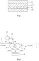
- FIG. 1 is a cross-sectional view illustrating a configuration of an anti-glare film according to an embodiment of the present invention.
- FIG. 2 is a view illustrating a method of manufacturing an anti-glare film according to a third embodiment.
- FIG. 3 is a view illustrating one example of a schematic configuration of a sparkle measurement apparatus according to an embodiment of the present invention.
- FIG. 1 is a cross-sectional view illustrating a configuration of an anti-glare film 1 according to an embodiment of the present invention.
- the anti-glare film 1 is attached on a surface of a display 16 a of a display device 16 (see FIG. 3 ).
- the anti-glare film 1 includes a substrate film 2 , an anti-glare layer 3 , and an adhesive layer 4 .
- the substrate film 2 is arranged between the surface of the display 16 a and the anti-glare layer 3 , and supports the anti-glare layer 3 .
- the adhesive layer 4 is arranged between the surface of the display 16 a and the substrate film 2 , and fixes the anti-glare film 1 to the surface of the display 16 a.
- the anti-glare layer 3 is formed on at least one surface of the substrate film 2 .
- the anti-glare layer 3 provides anti-glare property to the anti-glare film 1 , and prevents external light from reflecting on the display 16 a by causing the external light to scatter and reflecting.
- the anti-glare layer 3 also functions as a hard coat (HC) layer that covers the surface of the substrate film 2 .
- the anti-glare layer 3 includes a plurality of phase-separable resin components.
- the anti-glare layer 3 is set to have a sparkle value falling within a range from 6 to 10.
- the sparkle value is defined based on a value of a standard deviation of luminance distribution of the display 16 a under a condition in which the anti-glare film 1 is attached on the surface of the display 16 a .
- the sparkle value can be obtained through use of a sparkle measurement apparatus 10 described later.
- transmission image clarity image clarity
- the transmission image clarity is a scale for quantitating unsharpness and distortion of light transmitted through the anti-glare layer 3 , and is a measured value obtained by a measurement method in accordance with JIS K7105.
- the anti-glare layer 3 is set to have a haze value falling within a range of 50% or less.
- the haze value in the present embodiment is a measured value obtained by a measurement method in accordance with JIS K7136.
- specular gloss 60-degree gloss measured with 60-degree specular gloss has a value falling within 30% or less.
- specular gloss is generally referred to as gloss indicating a value of a degree of specularly reflected light on an object surface, and is a measured value obtained by a measurement method in accordance with JIS K7136.
- the anti-glare film 1 according to the present embodiment can be designed through use of the sparkle value being an objective quantitative evaluation for sparkle, and thus the sparkle value falls within a range from 6 to 10.
- sparkle can be stably suppressed within a desired ranged.
- the value of the transmissive clarity can be suppressed within a range of 60% or less while suppressing the haze value to fall within a range of 50% or less.
- high anti-glare property can be achieved while suppressing unsharpness of a character.
- the specular gloss (60-degree gloss) measured with 60-degree specular gloss is set to a value falling within a range of 30% or less, which is a small value, and hence the anti-glare layer 3 can suppress reflection of external light on the surface of the display 16 a.
- the adhesive layer 4 is arranged between the surface of the display 16 a and the substrate film 2 , and fixes the anti-glare film 1 to the surface of the display 16 a.
- an anti-glare layer 3 formed by the phase separation method as the anti-glare layer 3 in a first embodiment an anti-glare layer 3 formed by the fine particle dispersion method as the anti-glare layer 3 in a second embodiment, and an anti-glare layer 3 formed by the transfer molding method as the anti-glare layer 3 in a third embodiment.
- the substrate film 2 for example, glass, ceramics, and a resin can be exemplified.
- the resin a resin similar to a material of the anti-glare layer 3 can be used.
- the preferable material of the substrate film 2 include a transparent polymer such as a cellulose derivative (cellulose acetate such as cellulose triacetate (TAC) and cellulose diacetate, and the like), a polyester resin (polyethylene terephthalate (PET), polyethylene naphthalate (PEN), polybutylene terephthalate (PBT), polyarylate resin, and the like), a polysulfone resin (polysulfone, polyethersulfone (PES), and the like), a polyetherketone resin (polyetherketone (PEK), polyetheretherketone (PEEK), and the like), a polycarbonate resin (PC), a polyolefin resin (polyethylene, polypropylene, and the like), a cyclic polyole
- the substrate film 2 may be stretched uniaxially or biaxially, but preferably is optically isotropic and has a low index of refraction.
- an unstretched film can be exemplified.
- a thickness dimension of the substrate film 2 can be set as appropriate, and preferably is a value falling within a range of, for example, from 5 ⁇ m to 2000 ⁇ m, more preferably a value falling within a range from 15 ⁇ m to 1000 ⁇ m, even more preferably a value falling within a range from 20 ⁇ m to 500 ⁇ m.
- the anti-glare layer 3 in the first embodiment has a phase separation structure with a plurality of resin components.
- the anti-glare layer 3 in the first embodiment has a structure in which a plurality of long and slender protruding (string-like shape or thready shape) parts are formed on the surface due to a phase separation structure with a plurality of resin components.
- the long and slender protruding parts are branched, and form a co-continuous phase structure in a dense state.
- the anti-glare layer 3 in the first embodiment exerts anti-glare property with the plurality of long and slender protruding parts and recessed parts positioned between the adjacent long and slender protruding parts.
- the anti-glare film 1 includes the anti-glare layer 3 described above, and hence is excellent in balance of the haze value and the transmission image clarity.
- the long and slender protruding parts are formed substantially in a mesh-like shape. Consequently, the surface of the anti-glare layer 3 in the first embodiment has a mesh-like structure, in other words, a plurality of continuous or partly-missing irregular loop structures.
- the structure described above is formed on the anti-glare layer 3 in the first embodiment, and thus formation of a lens shaped (sea-island shaped) convex part on the anti-glare layer 3 can be prevented.
- light transmitted from the display 16 a through the anti-glare layer 3 in the first embodiment is prevented from being refracted on the recesses and protrusions on the surface of the anti-glare layer 3 , and the pixels of the display 16 a are prevented from being magnified and visually recognized due to a lens effect of the recesses and protrusions on the surface of the anti-glare layer 3 .
- sparkle on the display 16 a can be suppressed.
- the plurality of long and slender protruding parts may be independent from or continuous to each other.
- the phase separation structure of the anti-glare layer 3 in the first embodiment is formed by spinodal decomposition from a liquid phase (wet spinodal decomposition) through use of a solution being a raw material of the anti-glare layer 3 .
- description of Patent Document 4 can be referred.
- the plurality of resin components included in the anti-glare layer 3 in the first embodiment are only required to be phase-separable. From a viewpoint of obtaining the anti-glare layer 3 having the long and slender protruding parts and achieving high scratch resistance, the plurality of resin components included in the anti-glare layer 3 preferably include a polymer and a curable resin.
- thermoplastic resin As a polymer included in the anti-glare layer 3 in the first embodiment, for example, a thermoplastic resin is exemplified.
- the thermoplastic resin include a styrene resin, a (meth)acrylic polymer, an organic acid vinyl ester polymer, a vinyl ether polymer, a halogen-containing resin, an olefin resin (including an alicyclic olefin resin), a polycarbonate resin, a polyester resin, a polyamide resin, a thermoplastic polyurethane resin, a polysulfone resin (polyethersulfone, polysulfone, and the like), a polyphenylene ether resin (polymer of 2,6-xylenol), a cellulose derivative (cellulose esters, cellulose carbamates, cellulose ethers, and the like), a silicone resin (polydimethylsiloxane, polymethylphenylsiloxane, and the like), and rubber or elast
- a polymer having a functional group participating in a cure reaction or a functional group reacting with a curable compound may also be exemplified.
- the polymer may have a functional group at a principal chain or at a side chain.
- Examples of the functional group include a condensable group, a reactive group (such as a hydroxyl group, an acid anhydride group, a carboxyl group, an amino group or an imino group, an epoxy group, a glycidyl group, and an isocyanate group), and a polymerizable group (a C 2-6 alkenyl group such as vinyl, propenyl, isopropenyl, butenyl, and allyl, a C 2-6 alkynyl group such as ethynyl, propynyl, and butynyl, a C 2-6 alkenylidene group such as vinylidene, and a group having a polymerizable group thereof (such as (meth)acryloyl group).
- a polymerizable group is preferred.
- the anti-glare layer 3 in the first embodiment includes a plurality of kinds of polymers.
- Each of the polymers may be phase-separable from a liquid phase by spinodal decomposition, or may be non-miscible to each other.
- a combination of a first polymer and a second polymer included in the plurality of kinds of polymers is not particularly limited, and the polymers that are non-miscible to each other at a temperature around a process temperature may be used.
- the second polymer may be a cellulose derivative (cellulose esters such as cellulose acetate propionate), a (meth)acrylic resin (polymethyl methacrylate and the like), an alicyclic olefin resin (a polymer having norbornene as a monomer, and the like), a polycarbonate resin, a polyester resin (poly C 2-4 alkylene arylate copolyester and the like, and the like), and the like.
- cellulose derivative cellulose esters such as cellulose acetate propionate
- a (meth)acrylic resin polymethyl methacrylate and the like
- an alicyclic olefin resin a polymer having norbornene as a monomer, and the like
- a polycarbonate resin a polyester resin (poly C 2-4 alkylene arylate copolyester and the like, and the like), and the like.
- the second polymer may be a styrene resin (polystyrene, a styrene-acrylonitrile copolymer, and the like), a (meth)acrylic resin, an alicyclic olefin resin (a polymer having norbornene as a monomer, and the like), a polycarbonate resin, a polyester resin (poly C 2-4 alkylene arylate copolyester and the like), and the like.
- styrene resin polystyrene, a styrene-acrylonitrile copolymer, and the like
- a (meth)acrylic resin an alicyclic olefin resin (a polymer having norbornene as a monomer, and the like)
- a polycarbonate resin a polyester resin (poly C 2-4 alkylene arylate copolyester and the like), and the like.
- the plurality of kinds of polymers may include at least cellulose esters (cellulose C 2-4 alkylcarboxylates such as cellulose diacetate, cellulose triacetate, cellulose acetate propionate, and cellulose acetate butyrate).
- cellulose esters cellulose C 2-4 alkylcarboxylates such as cellulose diacetate, cellulose triacetate, cellulose acetate propionate, and cellulose acetate butyrate.
- a precursor of the curable resin included in the plurality of resin components is cured by active energy rays (such as ultraviolet rays and electron beams) at the time of manufacturing the anti-glare layer 3 , and thus the phase separation structure of the anti-glare layer 3 in the first embodiment is fixed. Further, with the curable resin as described above, the anti-glare layer 3 in the first embodiment is provided with scratch resistance and durability.
- active energy rays such as ultraviolet rays and electron beams
- At least one polymer included in the plurality of kinds of polymers is preferably a polymer having a functional group, which is reactable with a curable resin precursor, at a side chain.
- a thermoplastic resin or other polymers may be included in addition to the two non-miscible polymers described above.
- a mass ratio M1/M2 of mass M1 of the first polymer to a mass M2 of the second polymer and a glass transfer temperature of the polymers can be set as appropriate.
- the curable resin precursor for example, there can be exemplified a curable compound having a functional group that undergoes a reaction by active energy rays (such as ultraviolet rays and electron beams), heat, and the like and forming a resin (particularly, a cured resin or a crosslinked resin) by curing or crosslinking by the functional group.
- active energy rays such as ultraviolet rays and electron beams
- heat heat, and the like
- forming a resin particularly, a cured resin or a crosslinked resin
- thermosetting compound or a thermosetting resin examples include a thermosetting compound or a thermosetting resin (a low molecular weight compound having an epoxy group, a polymerizable group, an isocyanate group, an alkoxysilyl group, a silanol group, and the like (for example, an epoxy resin, an unsaturated polyester resin, a urethane resin, and a silicone resin)), and a photocurable (ionizing radiation-curable) compound that is cured by ultraviolet rays, electron beams, or the like (an ultraviolet light curable compound such as photocurable monomer and oligomer).
- a thermosetting compound or a thermosetting resin a low molecular weight compound having an epoxy group, a polymerizable group, an isocyanate group, an alkoxysilyl group, a silanol group, and the like (for example, an epoxy resin, an unsaturated polyester resin, a urethane resin, and a silicone resin)
- the preferable curable resin precursor there can be exemplified a photocurable compound that is cured by ultraviolet rays, electron beams, or the like in a short period of time.
- the ultraviolet light curable compound is particularly practical.
- the photocurable compound preferably includes 2 or more (preferably about from 2 to 15 and more preferably about from 4 to 10) polymerizable unsaturated bonds in the molecule. Consequently, resistance such as scratch resistance can be improved.
- the photocurable compound preferably is epoxy (meth)acrylate, urethane (meth)acrylate, polyester (meth)acrylate, silicone (meth)acrylate, and a polyfunctional monomer having at least two polymerizable unsaturated bonds.
- the curable resin precursor may include a curing agent in accordance with a type thereof.
- the thermosetting resin precursor may include a curing agent such as amines and polyhydric carboxylic acids
- the photocurable resin precursor may include a photopolymerization initiator.
- the photopolymerization initiator include the known components such as acetophenones or propiophenones, benzyls, benzoins, benzophenones, thioxanthones, and acylphosphine oxides.
- the curable resin precursor may include a curing accelerator.
- the photocurable resin precursor may include a photocuring accelerator (for example, tertiary amines (such as dialkylaminobenzoic acid ester), and a phosphine photopolymerization accelerator.
- the combination for phase separation include (a) a combination in which a plurality of kinds of non-miscible polymers are phase-separated from each other, (b) a combination in which a polymer and a curable resin precursor that are non-miscible are phase-separated from each other, (c) a combination in which a plurality of non-miscible curable resin precursors are phase-separated from each other.
- the polymers and a cured resin generated by curing of the curable resin precursor or a crosslinked resin have refractive indexes different from each other.
- the plurality of kinds of polymers (the first polymer and the second polymer) have refractive indexes different from each other.
- a difference of the refractive indexes of the polymers and the cured resin or the crosslinked resin, and a difference of the refractive indexes of the plurality kinds of polymers (the first polymer and the second polymer) are preferably values falling within a range from 0 to 0.2, and more preferably values falling within a range from 0 to 0.07.
- the anti-glare layer 3 may include a plurality of fine particles (filler) dispersed in a matrix resin.
- the fine particle may be any of an organic fine particle or an inorganic fine particle, and the plurality of fine particles may include a plurality of kinds of fine particles.
- a crosslinked acrylic particle and a crosslinked styrene particle can be exemplified.
- a silica particle and an alumina particle can be exemplified.
- a difference in refractive indexes of the fine particles and the matrix resin included in the anti-glare layer 3 may be set to a value falling within a range from 0 to 0.2.
- the difference in refractive indexes is further desirably a value falling within a range from 0 to 0.15, and more desirably a value falling within a range from 0 to 0.07.
- An average particle diameter of the fine particles is not particularly limited, and can be set to a value falling a range of, for example, from 0.5 ⁇ m to 5.0 ⁇ m.
- the average particle diameter is further desirably a value falling within a range from 0.5 ⁇ m to 4.0 ⁇ m, and more desirably a value falling within a range from 1.0 ⁇ m to 3.0 ⁇ m.
- the average particle diameter described herein is a 50%-volume average particle diameter in a coulter counter method (the same holds true in the average particle diameter mentioned below).
- the fine particle may be solid or hollow.
- the thickness dimension of the anti-glare layer 3 in the first embodiment can be set as appropriate, and is desirably a value falling within a range, for example, from 0.3 ⁇ m to 20 ⁇ m, more desirably a value falling within a range from 1 ⁇ m to 15 ⁇ m, and more desirably a value falling within a range from 1 ⁇ m to 10 ⁇ m.
- the thickness dimension can be set to a value falling within a range from 2 ⁇ m to 10 ⁇ m (particularly, a value falling within a range from 3 ⁇ m to 7 ⁇ m).
- the anti-glare film 1 from which the substrate film 2 is omitted may be configured.
- the thickness dimension of the anti-glare layer 3 is desirably a value falling within a range from 1 ⁇ m to 100 ⁇ m, and more desirably a value falling within a range from 3 ⁇ m to 50 ⁇ m.
- the anti-glare layer 3 in the first embodiment may include a known additive such as organic or inorganic particles, a stabilizer (antioxidant, an ultraviolet absorbing agent, and the like), a surfactant, a water soluble polymer, a filler, a crosslinker, a coupling agent, a coloring agent, a flame retardant, a lubricant, wax, an antiseptic, a viscosity adjusting agent, a thickening agent, a leveling agent, and an anti-foaming agent, as long as an optical property is not impaired.
- a known additive such as organic or inorganic particles, a stabilizer (antioxidant, an ultraviolet absorbing agent, and the like), a surfactant, a water soluble polymer, a filler, a crosslinker, a coupling agent, a coloring agent, a flame retardant, a lubricant, wax, an antiseptic, a viscosity adjusting agent, a thickening agent, a level
- a method of manufacturing the anti-glare film 1 according to the first embodiment includes preparing a solution being a raw material of the anti-glare layer 3 in the first embodiment (hereinafter, also referred to simply as the “solution”), forming a phase separation structure by spinodal decomposition from a liquid phase while coating a surface of a prescribed support body (the substrate film 2 in the first embodiment) with the solution prepared in preparing and evaporating a solvent in the solution, and curing a curable resin precursor after forming.
- the solution including the solvent and a resin composition forming the anti-glare layer 3 in the first embodiment is prepared.
- the solvent may be selected in accordance with kinds and solubility of the polymers included in the anti-glare layer 3 described above and the curable resin precursor.
- the solvent is only required to dissolve uniformly at least solid contents (the plurality of kinds of polymers, the curable resin precursor, a reaction initiator, and an additive thereto).
- the solvent examples include ketones (acetone, methyl ethyl ketone, methyl isobutyl ketone, cyclohexanone, and the like), ethers (dioxane, tetrahydrofuran, and the like), aliphatic hydrocarbons (hexane and the like), alicyclic hydrocarbons (cyclohexane and the like), aromatic hydrocarbons (toluene, xylene, and the like), halogenated carbons (dichloromethane, dichloroethane, and the like), esters (methyl acetate, ethyl acetate, butyl acetate, and the like), water, alcohols (ethanol, isopropanol, butanol, cyclohexanol, and the like), cellosolves (methyl cellosolve, ethyl cellosolve, and the like), cellosolve acetates, sulfoxides (dimethyl sul
- thermoplastic resin a thermoplastic resin, a photocurable compound, a photopolymerization initiator, and a composition including a thermoplastic resin and a photocurable compound are desired.
- a composition including the plurality of kinds of non-miscible polymers, a photocurable compound, and the photopolymerization initiator is desired.
- a concentration of solutes (the polymers, the curable resin precursor, the reaction initiator, and the other additive) in the liquid mixture can be adjusted as long as the phase separation of the plurality of resin components is caused and a flow-casting property, a coating property, and the like are not impaired.
- the solution prepared in preparing is flow-casted on or coats the surface of the support body (here, as one example, the substrate film 2 ).
- the flow-casting method or the coating method of the solution include the known method such as a spray, a spinner, a roll coater, an air knife coater, a blade coater, a rod coater, a reverse coater, a bar coater, a comma coater, a dip, a dip squeeze coater, a die coater, a gravure coater, a micro gravure coater, and a silk screen coater.
- the solvent is evaporated and removed through drying from the solution which is flow-casted on or coats the surface of the support body.
- the phase separation of the plurality of resin components by spinodal decomposition from a liquid phase is caused, and a phase separation structure with a relatively regular inter-phase distance (a pitch or a mesh diameter) is formed.
- a co-continuous phase structure of the long and slender protruding parts can be formed by setting a drying condition and formulation that increase melt flowability of the resin components after evaporation of the solvent to some extent.
- Evaporation of the solvent is preferably performed by heating and drying because the long and slender protruding parts are easily formed on the surface of the anti-glare layer 3 in the first embodiment.
- a drying temperature is excessively low or a drying time period is excessively short, a quantity of heat is insufficiently provided to the resin components.
- melt flowability of the resin components is degraded, and the long and slender protruding parts are hard to be formed, which should be noted.
- the drying temperature is excessively high or the drying time period is excessively long, the long and slender protruding parts that have been formed flow and reduce in height in some cases, although the structure thereof is maintained.
- the sparkle value, the specular gloss, the transmission image clarity, and the haze value of the anti-glare layer 3 which are set to values falling within ranges that satisfy the above-mentioned conditions, can be achieved by adjusting the drying temperature and the drying time period, and adjusting the height of the long and slender protruding parts or the like.
- a co-continuous phase structure in which phase separation structures are connected can be provided.
- phase separation of the plurality of resin components by spinodal decomposition from a liquid phase advances, a co-continuous phase structure is formed and coarsened. Consequently, the continuous phase becomes a non-continuous phase, and a liquid droplet phase structure (an isolated-phase sea-island structure in a ball-like shape, a spherical shape, a disk-like shape, an oval shape, or the like) is formed.
- a liquid droplet phase structure an isolated-phase sea-island structure in a ball-like shape, a spherical shape, a disk-like shape, an oval shape, or the like
- an intermediate structure between a co-continuous phase structure and a liquid droplet structure (a phase structure in a process of shifting the co-continuous phase to the liquid droplet phase) can also be formed.
- a layer with a surface having fine recesses and protrusions is formed.
- the curable resin precursor included in the solution is cured, and hence the phase separation structure formed in forming is fixed. As a result, the anti-glare layer 3 in the first embodiment is formed.
- Curing of the curable resin precursor can be performed by heating, irradiation with active energy rays, or a combination of these methods in accordance with a kind of the curable resin precursor.
- the active energy rays for irradiation are selected in accordance with a kind of a photocuring component or the like.
- the irradiation of the active energy rays may be performed in an inert gas atmosphere.
- the active energy rays are ultraviolet rays, a far ultraviolet light lamp, a low-pressure mercury lamp, a high-pressure mercury lamp, an ultrahigh-pressure mercury lamp, a halogen lamp, a laser light source (a helium-cadmium laser, an excimer laser, and the like), and the like may be used as the light source.
- the adhesive layer 4 when the adhesive layer 4 is formed, a solution including an adhesive component is adjusted, and then the solution coats the other surface of the substrate film 2 and is dried by the known method such as the flow-casting method or the coating method described above in forming. With this, formation can be completed.
- the anti-glare film 1 according to the first embodiment is manufactured.
- the anti-glare film 1 formed of only the anti-glare layer 3 can be obtained by peeling the anti-glare layer 3 from the support body.
- a non-peelable support body preferably, a transparent support body such as the substrate film 2
- the anti-glare film 1 having a layered structure including the support body (the substrate film 2 ) and the anti-glare layer 3 can be obtained.
- the recesses and protrusions described above can be formed on the anti-glare layer 3 by the above-mentioned spinodal decomposition in the first embodiment.
- the recesses and protrusions described above can also be formed on the anti-glare layer 3 .
- materials are selected, and thus a repulsive interaction between the fine particles, and a resin or a solvent other than the fine particles is strong at the time of forming the anti-glare layer 3 .
- the anti-glare layers 3 in the other embodiments are described by mainly focusing on differences from the first embodiment.
- the anti-glare layer 3 in the second embodiment includes a matrix resin and a plurality of fine particles dispersed in the matrix resin.
- the plurality of fine particles are formed in a spherical shape.
- the plurality of particles are not limited thereto, and may be formed in a substantially ball-like shape or an oval shape.
- the fine particle is formed to be solid, but may be formed to be hollow. When the fine particle is formed to be hollow, in a hollow part of the fine particle may be filled with air or other gases.
- the fine particles may be dispersed as primary particles, or a plurality of secondary particles formed by aggregation of a plurality of fine particles may be dispersed.
- a difference in refractive indexes of the matrix resin and the fine particles is set to a value falling within a range from 0 to 0.2.
- the difference in refractive indexes is further desirably a value falling within a range from 0 to 0.15, and more desirably a value falling within a range from 0 to 0.07.
- the fine particles have an average particle diameter set to a value falling within a range of from 0.5 ⁇ m to 5.0 ⁇ m.
- the average particle diameter of the fine particles is further desirably a value falling within a range from 0.5 ⁇ m to 4.0 ⁇ m, and more preferably a value falling within a range from 1.0 ⁇ m to 3.0 ⁇ m.
- variation in particle diameter of the fine particles is preferably small.
- an average particle diameter of 50 wt. % or greater of the fine particles included in the anti-glare layer 3 preferably has variation within 1.0 ⁇ m.
- a ratio G2/G1 of a weight G1 of the matrix resin of the anti-glare layer 3 to a total weight G2 of the plurality of fine particles included in the anti-glare layer 3 is set to a value falling within a range from 0.02 to 0.15.
- the ratio G2/G1 is preferably a value falling within a range from 0.04 to 0.15, and more preferably a value falling within a range from 0.04 to 0.12.
- the fine particles dispersed in the matrix resin may be inorganic or organic, and preferably have satisfactory transparency.
- plastic beads can be exemplified.
- the plastic beads include styrene beads (a refractive index of 1.59), melamine beads (a refractive index of 1.57), acrylic beads (a refractive index of 1.49), acryl-styrene beads (a refractive index of 1.54), polycarbonate beads, polyethylene beads, and the like.
- the plastic beads desirably have hydrophobic groups on surfaces thereof.
- styrene beads can be exemplified.
- the photocurable resin examples include a resin having a acrylate functional group such as a polyester resin with a relatively low molecular weight, a polyether resin, an acrylic resin, an epoxy resin, an urethane resin, an alkyd resin, a spiroacetal resin, a polybutadiene resin, a polythiol polyene resin, an oligomer such as a (meth)acrylate which is a polyfunctional compound such as polyhydric alcohol, a prepolymer, and a reactive diluent.
- a resin having a acrylate functional group such as a polyester resin with a relatively low molecular weight, a polyether resin, an acrylic resin, an epoxy resin, an urethane resin, an alkyd resin, a spiroacetal resin, a polybutadiene resin, a polythiol polyene resin, an oligomer such as a (meth)acrylate which is a polyfunctional compound such as polyhydric alcohol, a
- ком ⁇ онент ⁇ include a monofunctional monomer and a polyfunctional monomer of, for example, ethyl (meth)acrylate, ethylhexyl (meth)acrylate, styrene, methylstyrene, N-vinyl pyrrolidone, such as polymethylolpropane tri(meth)acrylate, hexanediol (meth)acrylate, tripropylene glycol di(meth)acrylate, diethylene glycol di(meth)acrylate, pentaerythritol tri(meth)acrylate, dipentaerythritol hexa(meth)acrylate, 1,6-hexanediol di(meth)acrylate, and neopentyl glycol di(meth)acrylate.
- ethyl (meth)acrylate ethylhexyl (meth)acrylate
- styrene methyl
- the photocurable resin is an ultraviolet light curable resin
- the photopolymerization initiator examples include acetophenones, benzophenones, Michler benzoyl benzoate, ⁇ -amyl oxime ester, tetramethylthiuram monosulfide, and thioxanthones.
- the photocurable resin is preferably used by mixing with a photosensitizer.
- a photosensitizer As the photosensitizer, n-butylamine, triethylamine, poly-n-butylphosphine, and the like can be exemplified.
- thermoplastic resin a publicly known thermoplastic resin
- examples of the thermoplastic resin include a styrene resin, a (meth)acrylate-based resin, a vinyl acetate-based resin, a vinyl ether resin, a halogen-containing resin, an alicyclic olefin resin, a polycarbonate resin, a polyester resin, a polyamide resin, a cellulose derivative, a silicone resin, rubber or elastomer, and the like.
- a resin which can be solved in an organic solvent, and is excellent particularly in moldability, film-formability, transparency, and weather resistance, is desired.
- solvent drying-type resin examples include a styrene resin, a (meth)acrylate-based resin, an alicyclic olefin resin, a polyester resin, and a cellulose derivative (cellulose esters and the like).
- a cellulose resin can be exemplified as a thermoplastic resin used as the solvent drying-type resin.
- the cellulose resin include a cellulose derivative such as cellulose nitrate, acetyl cellulose, acetyl butyl cellulose, ethyl cellulose, methyl cellulose, cellulose acetate propionate, and ethyl hydroxyethyl cellulose.
- a cellulose resin is used as the solvent drying-type resin, and thus the substrate film 2 and the anti-glare layer 3 can be brought into close contact with each other satisfactorily. Also, excellent transparency can be obtained in the anti-glare film 1 .
- examples of the solvent drying-type resin include a vinyl resin, an acetal resin, an acrylate-based resin, a polystyrene resin, a polyamide resin, and a polycarbonate resin.
- thermosetting resin examples include a phenol resin, a urea resin, a diallyl phthalate resin, a melamine resin, a guanamine resin, an unsaturated polyester resin, a polyurethane resin, an epoxy resin, an aminoalkyd resin, a melamine-urea co-condensated resin, a silicone resin, and a polysiloxane resin
- a crosslinker such as a photopolymerization initiator, a photopolymerization accelerator, a solvent, and a viscosity adjusting agent or the like may be used in combination.
- a method of manufacturing the anti-glare film 1 according to the second embodiment includes preparing a solution being a raw material of the anti-glare layer 3 in the second embodiment, coating a surface of a prescribed support body (the substrate film 2 in the second embodiment) with the solution prepared in preparing, and curing a resin in the solution used for coating.
- the solution including the solvent, and a resin composition and fine particles for forming the anti-glare layer 3 in the second embodiment is prepared.
- the solvent at least any of alcohols (such as isopropyl alcohol, methanol, and ethanol), ketones (such as methyl ethyl ketone (MEK), methyl isobutyl ketone (MIBK), and cyclohexanone), esters (such as methyl acetate, ethyl acetate, and butyl acetate), halogenated hydrocarbon, or aromatic hydrocarbon (such as toluene and xylene) can be exemplified.
- a publicly known leveling agent may further be added to solution. For example, by using a fluorine or silicone leveling agent, satisfactory scratch resistance can be provided to the anti-glare layer.
- the solution prepared in preparing is flow-casted on or coats the surface of the support body (here, as one example, the substrate film 2 ) by a method similar to that in the first embodiment.
- the solvent is evaporated and removed through drying from the solution which is flow-casted on or coats the surface of the support body.
- the matrix resin is a photocurable resin
- curing by ultraviolet light or electron beams is performed after coating.
- the ultraviolet light source a light source such as various types of mercury lamps, an ultraviolet ray carbon arc lamp, black light, and a metal halide lamp can be exemplified.
- a wavelength region of the ultraviolet light for example, a wavelength region from 190 nm to 380 nm can be exemplified.
- a publicly known electron beam accelerator can be exemplified.
- various electron beam accelerators such as a Van de Graaff type, a Cockcroft-Walton type, a resonant transformer type, an insulating core transformer type, a linear type, a dynamitron type, and a high-frequency type can be exemplified.
- the matrix resin included in the solution is cured, and hence the positions of the fine particles in the matrix resin are fixed. Consequently, the plurality of fine particles are dispersed in the matrix resin, and the anti-glare layer having a structure in which the recesses and protrusions are formed on the surface due to the fine particles is formed.
- a difference in refractive indexes of the matrix resin and the fine particles is set to fall within a predetermined range, and the plurality of fine particles are dispersed in the matrix resin. Consequently, sparkle on the display 16 a can be suppressed while securing satisfactory anti-glare property.
- the anti-glare layer 3 of the anti-glare film 1 according to the third embodiment has a structure in which recesses and protrusions are shaped on a surface on a side opposite to the substrate film 2 side.
- the anti-glare layer 3 in the third embodiment is formed of a resin layer.
- the resin layer is formed of the same material as that of the matrix resin included in the anti-glare layer 3 in the second embodiment, as one example.
- the anti-glare film 1 according to the third embodiment is manufactured by forming a coat layer formed of a curable resin on the substrate film 2 , shaping a surface of the coat layer into recesses and protrusions, and curing the coat layer.
- FIG. 2 is a view illustrating a method of manufacturing the anti-glare film 1 according to the third embodiment.
- an ultraviolet light curable resin is used as a curable resin.
- a layer of the ultraviolet light curable resin precursor coating the substrate film 2 (hereinafter, referred to as a coat layer) is pressed together with the substrate film 2 at a nip point of rolls 21 and 24 .
- the roll 24 is a roll-shaped die (an embossing roll) with fine recesses and protrusions formed on a circumferential surface thereof, and transfers the recesses and protrusions onto a surface of the coat layer when passing though the nip point N 2 of the rolls 21 and 24 .
- the coat layer onto which the recesses and protrusions are transferred from the roll 24 is cured by ultraviolet light emitted from a ultraviolet light lamp 26 provided below the rolls 21 and 24 . Consequently, the anti-glare layer 3 of the anti-glare film 1 according to the third embodiment is formed.
- the anti-glare film 1 according to the third embodiment thus manufactured is released from the roll 24 and conveyed in a predetermined direction by a roll 25 that is adjacent to and axially supported by the roll 24 .
- the recesses and protrusions on the surface of the roll 24 are formed through blasting by causing blast particles having a predetermined particle diameter to strike, and a shape of the recesses and protrusions formed on the coat layer of the anti-glare film 1 can be adjusted by adjusting a blast particle diameter.
- a polyethylene terephthalate (PET) film, a cellulose triacetate (TAC) film, a cyclo olefin polymer (COP) film, an acrylic resin film, or a polycarbonate resin film can suitably be used.
- FIG. 3 is a view illustrating one example of a schematic configuration of the sparkle measurement apparatus 10 according to an embodiment of the present invention.
- the sparkle measurement apparatus 10 is an apparatus that inspects an extent of sparkle on the display 16 a of the display device 16 on which the anti-glare film 1 is attached.
- the sparkle measurement apparatus 10 includes an enclosure 11 , an imaging device 12 , a holding portion (adjusting portion) 13 , an imaging device stand 14 , a display device stand (adjusting portion) 15 , and an image processing device 17 .
- the enclosure 11 is for providing a dark space being a measurement space for performing sparkle evaluation, and has a hollow rectangular parallelepiped shape.
- the imaging device 12 , the holding portion 13 , the imaging device stand 14 , the image display stand 15 , and the display device 16 being subjected to sparkle evaluation are housed in the enclosure 11 .
- the enclosure 11 has a configuration that prevents light from entering the enclosure 11 from outside at the time of imaging performed by the imaging device 12 .
- the holding portion 13 is a member in a bar-like shape extending in a vertical direction (in an up-and-down direction in FIG. 3 ).
- the base end of the holding portion 13 is fixed by the imaging device stand 14 , and the distal end thereof holds the imaging device 12 .
- the imaging device 12 is movable in the vertical direction by the holding portion 13 , and a relative distance between the display 16 a and the lens 18 can be changed.
- the display device 16 is placed on the upper surface of the image display stand 15 under a state in which the display 16 a with the anti-glare film 1 attached thereon faces the imaging device 12 .
- the image display stand 15 can support the display device 16 , and thus the surface of the display 16 a with the anti-glare film 1 attached thereon faces the imaging device 12 and becomes a horizontal surface.
- the image display stand 15 can move the display device 16 in the vertical direction, and thus a relative distance between the display 16 a and the lens 18 is changed.
- a size of an image displayed in the display 16 a is adjusted.
- a pixel size of the image displayed on the display 16 a which is captured by the imaging element of the imaging device 12 per unit pixel (for example, one pixel), is adjusted.
- the image processing device 17 executes data processing of the image data captured by the imaging device 12 . Specifically, the image processing device 17 obtains, from the image data captured by the imaging device 12 , a value of a standard deviation of luminance of the image displayed on the display 16 a.
- sparkle evaluation method for convenience of the evaluation, display is performed on the display 16 a having a surface on which the anti-glare film 1 is attached while the surface is caused to emit one-color light evenly (green as one example) in advance.
- a relative distance between the imaging device 12 and the display 16 a with the anti-glare film 1 attached thereon is adjusted in accordance with the number of effective pixels of the imaging element of the imaging device 12 .
- Emission lines of the pixels of the image displayed on the display 16 a with the anti-glare film 1 attached thereon are adjusted to be invisible or visible to an extent that does not affect sparkle evaluation in the image data captured by the imaging device 12 .
- the measurement area of the display 16 a with the anti-glare film 1 attached thereon is captured as an image by the imaging device 12 (imaging).
- imaging the imaging device 12
- at least one of an exposure time of the imaging device 12 or luminance of all the pixels of the display 16 a is adjusted, and thus image data relating to a gray scale image with 8-bit gradation display and an average luminance of 170 tones is obtained.
- the captured image data is input to the image processing device 17 .
- Each of Examples 1 to 3 is one example of the anti-glare film 1 that was manufactured by the phase separation method and satisfied the conditions of the sparkle value falling within a range of from 6 to 10, the specular gloss (60-degree gloss) of 30% or less, the transmission image clarity (image clarity) of 60% or less, which had an optical comb width of 0.5 mm, and the haze value of 50% or less.
- each of Examples 1 to 3 is one example of the anti-glare film 1 that was capable of satisfying the above-mentioned conditions with the recesses and protrusions formed on the surface of the anti-glare film 1 by the phase separation method.
- Example 4 is one example of the anti-glare film 1 that was manufactured by the fine particle dispersion method and satisfied the conditions of the sparkle value falling within a range from 6 to 10, the specular gloss (60-degree gloss) of 30% or less, the transmission image clarity (image clarity) of 60% or less, which had an optical comb width of 0.5 mm, and the haze value of 50% or less.
- a difference of refractive indexes of the matrix resin of the anti-glare layer 3 of the anti-glare film 1 and the plurality of fine particles dispersed in the matrix resin was adjusted to 0.07 or less, and thus Example 4 is one example of the anti-glare film 1 capable of satisfying the above-mentioned conditions.
- Urethane Acrylate “UA-53H” Available from Shin-Nakamura Chemical Co., Ltd., (a refractive index of 1.52).
- Dipentaerythritol hexaacrylate “DPHA” available from Daicel-Allnex Ltd., (a refractive index of 1.52).
- Silica (a refractive index of 1.46)-containing acrylated-based ultraviolet light curable compound: “Z-757-4RL” available from Aica Kogyo Company, Limited, (a refractive index of 1.52).
- Cellulose triacetate (TAC) film “FUJITACTG60UL” available from FUJIFILM Corporation.
- the solution was flow-casted on a PET film (the substrate film 2 ) using a wire bar (#18), and then was left in an oven at 80° C. for 1 minute to evaporate a solvent and form a coat layer having a thickness of approximately 9 ⁇ m. Further, for example, ultraviolet light curing processing of the coat layer was performed by irradiating the coat layer with ultraviolet light from an ultraviolet light lamp such as a high-pressure mercury lamp for approximately five seconds. In this manner, the anti-glare layer 3 was formed, and thus an anti-glare film of Example 1 was obtained.
- an ultraviolet light lamp such as a high-pressure mercury lamp
- the solution was flow-casted on a TAC film (the substrate film 2 ) using a wire bar (#12), and then was left in an oven at 80° C. for 1 minute to evaporate a solvent and form a coat layer having a thickness of approximately 4 ⁇ m. Further, ultraviolet light curing processing was performed by irradiating the coat layer with ultraviolet light from an ultraviolet light lamp for approximately five seconds. In this manner, the anti-glare layer 3 was formed, and thus an anti-glare film of Example 3 was obtained.
- a solution was prepared by mixing 50 parts by mass of a silica (a refractive index of 1.46)-containing acrylate-based ultraviolet light curable compound (a refractive index of 1.52) and 50 parts by mass of 1-butanol.
- the solution was flow-casted on a PET film (the substrate film 2 ) using a wire bar (#16), and then was left in an oven at 80° C. for 1 minute to evaporate a solvent and form a coat layer having a thickness of approximately 7 ⁇ m. Further, ultraviolet light curing processing was performed by irradiating the coat layer with ultraviolet light from an ultraviolet light lamp for approximately five seconds. In this manner, the anti-glare layer 3 was formed, and thus an anti-glare film of Example 4 was obtained. Note that, when G1 indicated the weight of the matrix resin (acrylate-based ultraviolet light curable compound) and G2 indicated a weight of the fine particles (silica) included in the anti-glare layer 3 , the ratio G2/G1 of those weights was 0.14.
- the resin composition was applied on the transparent base, and was dried for one minute while purging drying air at a flow speed of 1 m/s at 85° C. Note that, the coating thickness is 5 ⁇ m.
- UV light curing processing was performed by irradiating a transparent resin with ultraviolet light from an ultraviolet light lamp (200 mJ/cm 2 in a nitrogen atmosphere). In this manner, the anti-glare layer 3 was formed, and thus an anti-glare film of Comparative Example 1 was obtained.
- triacetyl cellulose available from FUJIFILM Corporation, a thickness of 80 ⁇ m was prepared.
- the resin composition was applied on the transparent base, and was dried for one minute while purging drying air at a flow speed of 0.2 m/s at 70° C. Note that, the coating thickness is 3.5 ⁇ m.
- UV light curing processing was performed by irradiating a transparent resin with ultraviolet light from an ultraviolet light lamp (200 mJ/cm 2 in a nitrogen atmosphere). In this manner, the anti-glare layer 3 was formed, and thus an anti-glare film of Comparative Example 2 was obtained.
- triacetyl cellulose available from FUJIFILM Corporation, a thickness of 80 ⁇ m was prepared.
- Pentaerythritol triacrylate (“PE-3A” available from Kyoeisha Chemical Co., Ltd., a refractive index of 1.53) was used as a transparent resin. Then, with respect to 100 parts by mass of the transparent resin, 26 parts by mass of silica particles (“SS50F” available from Tosoh Silica Corporation, a refractive index of 1.47, an average particle diameter of 1.1 ⁇ m) and 6.6 parts by mass of polystyrene particles (a refractive index of 1.59, an average particle diameter of 3.5 ⁇ m) were included as transparent particles. Then, 5.3 parts by mass of the photopolymerization initiator A and 138 parts by mass of toluene (a boiling point at 110° C.) as a solvent are mixed with each other. As a result, the resin composition was obtained.
- silica particles available from Tosoh Silica Corporation, a refractive index of 1.47, an average particle diameter of 1.1 ⁇ m
- the resin composition was applied on the transparent base, and was dried for one minute while purging drying air at a flow speed of 0.2 m/s at 90° C. Note that, the coating thickness is 5 ⁇ m.
- UV curing processing was performed by irradiating a transparent resin with ultraviolet light from an ultraviolet light lamp (200 mJ/cm 2 in a nitrogen atmosphere). In this manner, the anti-glare layer 3 was formed, and thus an anti-glare film of Comparative Example 3 was obtained.
- Each of the anti-glare films in Comparative Examples 4 and 5 was manufactured by forming, on a substrate film, a coat layer which was formed of an ultraviolet light curable resin and had a surface with recesses and protrusions transferred thereon through use of a die.
- the manufacturing process of the anti-glare film with the transfer molding method has already described above, and hence detailed description thereof is omitted.
- the method of manufacturing the anti-glare film in Comparative Examples 4 and 5 included (a) coating the substrate film with the ultraviolet light curable resin precursor, (b) manufacturing the roll-shaped die having recesses and protrusions on the surface thereof by causing the blast particles to strike, (c) transferring the recesses and protrusions onto the surface of the ultraviolet light curable resin precursor that coated the substrate film, through use of the roll-shaped die, and (d) forming the coat layer having the surface with the recesses and protrusions formed thereon by curing, by irradiation with ultraviolet light, the ultraviolet light curable resin precursor onto which the recesses and protrusions are transferred.
- a roll-shaped die was manufactured while varying a value of a blast particle diameter to fall within a range of from 10 ⁇ m to 40 ⁇ m, and two kinds of films (Comparative Examples 4 and 5) having different haze (Hz) values were manufactured by the above-mentioned manufacturing methods.
- TAC cellulose triacetate
- Measurement was performed using a haze meter (“NDH-5000W” available from NIPPON DENSHOKU INDUSTRIES CO., LTD.) in accordance with JIS K7136.
- the haze was measured under a condition in which the surface having the structure with the recesses and protrusions was on a side of an optical receiver.
- Measurement was performed using a mapping measuring instrument (“ICM-1T” available from Suga Test Instruments Co., Ltd.) in accordance with JIS K7105 under a condition in which the anti-glare film is installed, and thus the film-forming direction of the anti-glare film and the comb tooth direction of the optical comb were parallel with each other.
- the optical comb width was set to 0.5 mm.
- the display device 16 As the display device 16 , a smartphone (“Galaxy S4” available from Samsung Electronics Co., Ltd.) was used, and each of the sample anti-glare films was attached on the surface of the display 16 a thereof by an optical clear adhesive. Note that, the display 16 a of the smartphone has a resolution of 441 ppi. Further, the sparkle measurement apparatus 10 available from Komatsu NTC Ltd. was used, and a standard deviation (a sparkle value) of luminance distribution of the display 16 a through each of the sample anti-glare films was measured.
- At the time of the measurement at least one of an exposure time of the imaging device 12 or luminance of all the pixels of the display 16 a was adjusted, and thus image data relating to a gray scale image with 8-bit gradation display and an average luminance of 170 tones was obtained.
- the anti-glare films satisfying the above-mentioned conditions were able to be obtained.
- the recesses and protrusions satisfying the above-mentioned conditions were able to be formed on the surface of the anti-glare film 1 by setting kinds of phase separation materials to be combined, a heating temperature for composition in a drying process, a flow rate of a drying air caused to blow against the composition, or a linear speed as in Examples 1 to 3.
- the anti-glare film 1 satisfying the above-mentioned conditions was able to be formed in the following manner. That is, fine particles to be dispersed in the matrix resin were selected. Thus, a difference of refractive indexes of the fine particles and the matrix resin was set to a value falling within a range from 0 to 0.07, and the ratio G2/G1 of the weight G1 of the matrix resin to the total weight G2 of the plurality of fine particles included in the anti-glare layer falls within a range from 0.02 to 0.15. Then, manufacturing was performed under the manufacturing conditions provided in Example 4. That is, the fine particle dispersion method in Example 4, the following matter is conceivable.
- the anti-glare film satisfying the above-mentioned conditions was not able to be manufactured. That is, in Comparative Examples 1 and 2, a difference in refractive indexes of the fine particles and the matrix resin was greater than 0.07.
- the ratio G2/G1 of the weight G1 of the matrix resin to the total weight G2 of the plurality of fine particles included in the anti-glare layer was outside a range from 0.02 to 0.15.
- the recesses and protrusions controlled statistically were not able to be formed on the anti-glare film by the transfer molding method based on the raw materials and the manufacturing conditions in Comparative Examples 4 and 5, unlike the phase separation method as in, for example, Examples 1 to 3.
- the anti-glare film satisfying the above-mentioned conditions was not able to be manufactured.
- the present invention is not limited to the above-mentioned embodiments, and change, addition, or elimination may be made to the configurations and the methods without departing from the gist of the present invention.
- the fine particles in the second embodiment may be dispersed in the matrix resin of the anti-glare layer 3 in the first embodiment or the third embodiment.
Landscapes
- Physics & Mathematics (AREA)
- General Physics & Mathematics (AREA)
- Optics & Photonics (AREA)
- Engineering & Computer Science (AREA)
- Chemical & Material Sciences (AREA)
- Dispersion Chemistry (AREA)
- Manufacturing & Machinery (AREA)
- Theoretical Computer Science (AREA)
- Optical Elements Other Than Lenses (AREA)
- Laminated Bodies (AREA)
- Devices For Indicating Variable Information By Combining Individual Elements (AREA)
Applications Claiming Priority (4)
| Application Number | Priority Date | Filing Date | Title |
|---|---|---|---|
| JP2017-151463 | 2017-08-04 | ||
| JPJP2017-151463 | 2017-08-04 | ||
| JP2017151463 | 2017-08-04 | ||
| PCT/JP2018/023953 WO2019026471A1 (ja) | 2017-08-04 | 2018-06-25 | 防眩フィルム |
Related Parent Applications (1)
| Application Number | Title | Priority Date | Filing Date |
|---|---|---|---|
| PCT/JP2018/023953 A-371-Of-International WO2019026471A1 (ja) | 2017-08-04 | 2018-06-25 | 防眩フィルム |
Related Child Applications (1)
| Application Number | Title | Priority Date | Filing Date |
|---|---|---|---|
| US18/194,302 Division US11880051B2 (en) | 2017-08-04 | 2023-03-31 | Anti-glare film |
Publications (2)
| Publication Number | Publication Date |
|---|---|
| US20200166678A1 US20200166678A1 (en) | 2020-05-28 |
| US11650357B2 true US11650357B2 (en) | 2023-05-16 |
Family
ID=65233948
Family Applications (3)
| Application Number | Title | Priority Date | Filing Date |
|---|---|---|---|
| US16/618,530 Active 2039-03-22 US11650357B2 (en) | 2017-08-04 | 2018-06-25 | Anti-glare film |
| US18/194,302 Active US11880051B2 (en) | 2017-08-04 | 2023-03-31 | Anti-glare film |
| US18/534,161 Pending US20240103206A1 (en) | 2017-08-04 | 2023-12-08 | Anti-glare film |
Family Applications After (2)
| Application Number | Title | Priority Date | Filing Date |
|---|---|---|---|
| US18/194,302 Active US11880051B2 (en) | 2017-08-04 | 2023-03-31 | Anti-glare film |
| US18/534,161 Pending US20240103206A1 (en) | 2017-08-04 | 2023-12-08 | Anti-glare film |
Country Status (5)
| Country | Link |
|---|---|
| US (3) | US11650357B2 (ja) |
| JP (1) | JP6743305B2 (ja) |
| KR (1) | KR102300811B1 (ja) |
| CN (2) | CN110869821B (ja) |
| WO (1) | WO2019026471A1 (ja) |
Families Citing this family (6)
| Publication number | Priority date | Publication date | Assignee | Title |
|---|---|---|---|---|
| JP6837018B2 (ja) * | 2018-01-29 | 2021-03-03 | 株式会社ダイセル | 樹脂成形品の製造方法 |
| CN117425838A (zh) * | 2021-06-22 | 2024-01-19 | 株式会社大赛璐 | 防眩膜 |
| TWI789017B (zh) * | 2021-09-17 | 2023-01-01 | 明基材料股份有限公司 | 高霧度防眩膜以及高霧度防眩抗反射膜 |
| US20230092571A1 (en) * | 2021-09-17 | 2023-03-23 | Benq Materials Corporation | High-haze anti-glare film and high-haze anti-glare anti-reflection film |
| JP7347627B2 (ja) * | 2021-10-28 | 2023-09-20 | 大日本印刷株式会社 | 防眩フィルム及び画像表示装置 |
| WO2024070996A1 (ja) | 2022-09-30 | 2024-04-04 | 大日本印刷株式会社 | 光学フィルム、並びに、前記光学フィルムを用いた偏光板、表面板、画像表示パネル及び画像表示装置、並びに、前記光学フィルムの製造方法、並びに、光学フィルムの選定方法、並びに、指紋拭き取り性の評価方法 |
Citations (29)
| Publication number | Priority date | Publication date | Assignee | Title |
|---|---|---|---|---|
| US20020012086A1 (en) | 2000-07-24 | 2002-01-31 | Tatsou Uchida | Transmittable light-scattering sheets |
| JP2003207945A (ja) | 2002-01-16 | 2003-07-25 | Canon Inc | ブラックトナー |
| JP2006106224A (ja) | 2004-10-01 | 2006-04-20 | Daicel Chem Ind Ltd | 防眩性膜の製造方法 |
| JP2006113561A (ja) | 2004-09-16 | 2006-04-27 | Fuji Photo Film Co Ltd | 光散乱性フィルムの製造方法、該光散乱性フィルムを用いた偏光板、該偏光板を用いた液晶表示装置 |
| WO2006106757A1 (ja) | 2005-03-30 | 2006-10-12 | Dai Nippon Printing Co., Ltd. | 防眩性光学積層体 |
| JP2007090613A (ja) | 2005-09-28 | 2007-04-12 | Fujifilm Corp | 環状ポリオレフィンフィルム並びにその製造方法、それを用いた光学補償フィルム、偏光板、偏光板保護フィルムおよび液晶表示装置 |
| JP2007206482A (ja) | 2006-02-03 | 2007-08-16 | Canon Inc | 画像形成方法、非磁性一成分現像剤、画像形成装置及びプロセスカートリッジ |
| US20070298193A1 (en) * | 2004-09-16 | 2007-12-27 | Kazuhiro Nakamura | Method of Producing Light-Scattering Film, Polarizing Plate Comprising Light-Scattering Film and Liquid Crystal Display Device Comprising the Polarizing Plate |
| JP2009109702A (ja) | 2007-10-30 | 2009-05-21 | Sumitomo Chemical Co Ltd | 光拡散性シート |
| JP2009175041A (ja) | 2008-01-25 | 2009-08-06 | Asahi Kasei Corp | 表示画像のギラツキ評価方法 |
| US20090279176A1 (en) * | 2008-05-07 | 2009-11-12 | Industrial Technology Research Institute | Antiglare film and manufacturing method thereof |
| JP2010128429A (ja) | 2008-12-01 | 2010-06-10 | Canon Inc | 像加熱装置及びこの像加熱装置に用いられる加熱回転部材 |
| US20120013987A1 (en) * | 2010-07-16 | 2012-01-19 | Kazuhiro Oki | Light scattering sheet and method for producing the same |
| JP2012133066A (ja) | 2010-12-21 | 2012-07-12 | Samsung Yokohama Research Institute Co Ltd | 防眩フィルム |
| JP2013237211A (ja) | 2012-05-16 | 2013-11-28 | Nof Corp | 色調補正フィルム及びこれを用いた透明導電性フィルム |
| JP2014038362A (ja) | 2011-09-27 | 2014-02-27 | Nippon Paper Industries Co Ltd | 防眩ハードコートフィルム |
| JP2014085371A (ja) | 2012-10-19 | 2014-05-12 | Daicel Corp | 防眩フィルム及びその製造方法 |
| JP2014102356A (ja) | 2012-11-19 | 2014-06-05 | Suntechopt Co Ltd | 光学フィルムおよびその作製方法 |
| JP2015132744A (ja) | 2014-01-15 | 2015-07-23 | 株式会社きもと | アンチグレアフィルム |
| WO2015145618A1 (ja) | 2014-03-26 | 2015-10-01 | リンテック株式会社 | 防眩性ハードコートフィルム |
| JP2015172835A (ja) | 2014-03-11 | 2015-10-01 | 大日本印刷株式会社 | タッチパネル、表示装置及び光学シート、並びに光学シートの選別方法及び光学シートの製造方法 |
| JP2015196347A (ja) | 2014-04-02 | 2015-11-09 | 株式会社ダイセル | 透明積層フィルム及びその製造方法並びにタッチパネル用電極 |
| JP2016050950A (ja) | 2014-08-28 | 2016-04-11 | 大日本印刷株式会社 | 防眩フィルムの管理方法およびロール体 |
| JP2016107497A (ja) | 2014-12-05 | 2016-06-20 | 出光興産株式会社 | フィルム、延伸フィルムの製法、及び該フィルムを用いた包装材料 |
| JP2016170779A (ja) | 2015-03-13 | 2016-09-23 | 大日本印刷株式会社 | タッチパネル、表示装置及び光学シート |
| JP2016182744A (ja) | 2015-03-26 | 2016-10-20 | 富士フイルム株式会社 | 機能性フィルムおよび機能性フィルムの製造方法 |
| US20170052288A1 (en) * | 2014-04-25 | 2017-02-23 | 3M Innovative Properties Company | Textured coating for optical products |
| US20180252848A1 (en) * | 2015-09-15 | 2018-09-06 | 3M Innovative Properties Company | Low sparkle matte coats and methods of making |
| JP6719677B2 (ja) | 2017-08-04 | 2020-07-08 | 株式会社ダイセル | 防眩フィルム |
Family Cites Families (19)
| Publication number | Priority date | Publication date | Assignee | Title |
|---|---|---|---|---|
| JPS559505A (en) | 1978-07-05 | 1980-01-23 | Ricoh Co Ltd | Transfer and separating device of electrophotographic copier |
| US5933781A (en) | 1997-01-31 | 1999-08-03 | Qualcomm Incorporated | Pilot based, reversed channel power control |
| JP2004004417A (ja) * | 2002-04-18 | 2004-01-08 | Nitto Denko Corp | 光拡散性シート、光学素子および画像表示装置 |
| KR100634437B1 (ko) * | 2004-10-05 | 2006-10-16 | 삼성전자주식회사 | 반도체 소자 제조용 마스크 및 그 제조방법 |
| TWI411817B (zh) * | 2005-02-21 | 2013-10-11 | Dainippon Printing Co Ltd | Optical laminates |
| JP2007156132A (ja) * | 2005-12-06 | 2007-06-21 | Sumitomo Chemical Co Ltd | 防眩フィルム及び画像表示装置 |
| JP2007187952A (ja) * | 2006-01-16 | 2007-07-26 | Sumitomo Chemical Co Ltd | 防眩フィルム、その製造方法、そのための金型の製造方法、及び表示装置 |
| JP5007506B2 (ja) | 2006-01-31 | 2012-08-22 | ソニー株式会社 | 二次電池用非水電解質組成物及びこれを用いた非水電解質二次電池 |
| JP4958609B2 (ja) * | 2007-04-06 | 2012-06-20 | リンテック株式会社 | 防眩性ハードコートフィルム及びその製造方法 |
| JP2009180886A (ja) * | 2008-01-30 | 2009-08-13 | Nippon Shokubai Co Ltd | 防眩性積層体 |
| JP5163943B2 (ja) * | 2008-02-26 | 2013-03-13 | 住友化学株式会社 | 防眩フィルム、防眩性偏光板および画像表示装置 |
| JP2010020267A (ja) * | 2008-06-09 | 2010-01-28 | Sony Corp | 光学フィルムおよびその製造方法、防眩性フィルム、光学層付偏光子、ならびに表示装置 |
| JP5259334B2 (ja) * | 2008-10-17 | 2013-08-07 | リンテック株式会社 | 防眩性ハードコートフィルム及びそれを用いた偏光板 |
| JP5008734B2 (ja) * | 2010-03-18 | 2012-08-22 | 大日本印刷株式会社 | 防眩性フィルム、防眩性フィルムの製造方法、偏光板及び画像表示装置 |
| JP2014119552A (ja) * | 2012-12-14 | 2014-06-30 | Sumitomo Chemical Co Ltd | 防眩フィルムおよびそのための金型の製造方法、防眩フィルムの製造方法 |
| KR101751157B1 (ko) * | 2013-07-05 | 2017-06-26 | 다이니폰 인사츠 가부시키가이샤 | 방현 필름, 편광판, 액정 패널 및 화상 표시 장치 |
| JP6476582B2 (ja) * | 2014-04-23 | 2019-03-06 | 大日本印刷株式会社 | 積層体の製造方法、積層体、偏光板及び画像表示装置 |
| KR20160015161A (ko) * | 2014-07-30 | 2016-02-12 | 스미또모 가가꾸 가부시키가이샤 | 방현 필름 |
| KR20160015162A (ko) * | 2014-07-30 | 2016-02-12 | 스미또모 가가꾸 가부시키가이샤 | 방현 필름 |
-
2018
- 2018-06-25 KR KR1020207004373A patent/KR102300811B1/ko active IP Right Grant
- 2018-06-25 CN CN201880045264.5A patent/CN110869821B/zh active Active
- 2018-06-25 CN CN202111612684.7A patent/CN114347578A/zh active Pending
- 2018-06-25 JP JP2019533967A patent/JP6743305B2/ja active Active
- 2018-06-25 US US16/618,530 patent/US11650357B2/en active Active
- 2018-06-25 WO PCT/JP2018/023953 patent/WO2019026471A1/ja active Application Filing
-
2023
- 2023-03-31 US US18/194,302 patent/US11880051B2/en active Active
- 2023-12-08 US US18/534,161 patent/US20240103206A1/en active Pending
Patent Citations (35)
| Publication number | Priority date | Publication date | Assignee | Title |
|---|---|---|---|---|
| US20020012086A1 (en) | 2000-07-24 | 2002-01-31 | Tatsou Uchida | Transmittable light-scattering sheets |
| JP3559505B2 (ja) | 2000-07-24 | 2004-09-02 | ダイセル化学工業株式会社 | 透過型光散乱シート |
| JP2003207945A (ja) | 2002-01-16 | 2003-07-25 | Canon Inc | ブラックトナー |
| US20070298193A1 (en) * | 2004-09-16 | 2007-12-27 | Kazuhiro Nakamura | Method of Producing Light-Scattering Film, Polarizing Plate Comprising Light-Scattering Film and Liquid Crystal Display Device Comprising the Polarizing Plate |
| JP2006113561A (ja) | 2004-09-16 | 2006-04-27 | Fuji Photo Film Co Ltd | 光散乱性フィルムの製造方法、該光散乱性フィルムを用いた偏光板、該偏光板を用いた液晶表示装置 |
| JP2006106224A (ja) | 2004-10-01 | 2006-04-20 | Daicel Chem Ind Ltd | 防眩性膜の製造方法 |
| WO2006106757A1 (ja) | 2005-03-30 | 2006-10-12 | Dai Nippon Printing Co., Ltd. | 防眩性光学積層体 |
| US20090002831A1 (en) * | 2005-03-30 | 2009-01-01 | Dai Nippon Printing Co., Ltd. | Glare-Proofing Optical Laminate |
| JP2007090613A (ja) | 2005-09-28 | 2007-04-12 | Fujifilm Corp | 環状ポリオレフィンフィルム並びにその製造方法、それを用いた光学補償フィルム、偏光板、偏光板保護フィルムおよび液晶表示装置 |
| JP2007206482A (ja) | 2006-02-03 | 2007-08-16 | Canon Inc | 画像形成方法、非磁性一成分現像剤、画像形成装置及びプロセスカートリッジ |
| JP2009109702A (ja) | 2007-10-30 | 2009-05-21 | Sumitomo Chemical Co Ltd | 光拡散性シート |
| JP2009175041A (ja) | 2008-01-25 | 2009-08-06 | Asahi Kasei Corp | 表示画像のギラツキ評価方法 |
| US20090279176A1 (en) * | 2008-05-07 | 2009-11-12 | Industrial Technology Research Institute | Antiglare film and manufacturing method thereof |
| JP2010128429A (ja) | 2008-12-01 | 2010-06-10 | Canon Inc | 像加熱装置及びこの像加熱装置に用いられる加熱回転部材 |
| US20120013987A1 (en) * | 2010-07-16 | 2012-01-19 | Kazuhiro Oki | Light scattering sheet and method for producing the same |
| JP2012133066A (ja) | 2010-12-21 | 2012-07-12 | Samsung Yokohama Research Institute Co Ltd | 防眩フィルム |
| US20140254020A1 (en) | 2011-09-27 | 2014-09-11 | Nippon Paper Industries Co., Ltd. | Antiglare hard coat film |
| JP2014038362A (ja) | 2011-09-27 | 2014-02-27 | Nippon Paper Industries Co Ltd | 防眩ハードコートフィルム |
| JP2013237211A (ja) | 2012-05-16 | 2013-11-28 | Nof Corp | 色調補正フィルム及びこれを用いた透明導電性フィルム |
| JP2014085371A (ja) | 2012-10-19 | 2014-05-12 | Daicel Corp | 防眩フィルム及びその製造方法 |
| JP2014102356A (ja) | 2012-11-19 | 2014-06-05 | Suntechopt Co Ltd | 光学フィルムおよびその作製方法 |
| JP2015132744A (ja) | 2014-01-15 | 2015-07-23 | 株式会社きもと | アンチグレアフィルム |
| JP2015172835A (ja) | 2014-03-11 | 2015-10-01 | 大日本印刷株式会社 | タッチパネル、表示装置及び光学シート、並びに光学シートの選別方法及び光学シートの製造方法 |
| WO2015145618A1 (ja) | 2014-03-26 | 2015-10-01 | リンテック株式会社 | 防眩性ハードコートフィルム |
| US20170022343A1 (en) | 2014-04-02 | 2017-01-26 | Daicel Corporation | Transparent layered film, process for producing same, and electrode for touch panel |
| JP2015196347A (ja) | 2014-04-02 | 2015-11-09 | 株式会社ダイセル | 透明積層フィルム及びその製造方法並びにタッチパネル用電極 |
| US20170052288A1 (en) * | 2014-04-25 | 2017-02-23 | 3M Innovative Properties Company | Textured coating for optical products |
| JP2016050950A (ja) | 2014-08-28 | 2016-04-11 | 大日本印刷株式会社 | 防眩フィルムの管理方法およびロール体 |
| JP2016107497A (ja) | 2014-12-05 | 2016-06-20 | 出光興産株式会社 | フィルム、延伸フィルムの製法、及び該フィルムを用いた包装材料 |
| JP2016170779A (ja) | 2015-03-13 | 2016-09-23 | 大日本印刷株式会社 | タッチパネル、表示装置及び光学シート |
| JP2016182744A (ja) | 2015-03-26 | 2016-10-20 | 富士フイルム株式会社 | 機能性フィルムおよび機能性フィルムの製造方法 |
| US20180022881A1 (en) | 2015-03-26 | 2018-01-25 | Fujifilm Corporation | Functional film and method for producing functional film |
| US20180252848A1 (en) * | 2015-09-15 | 2018-09-06 | 3M Innovative Properties Company | Low sparkle matte coats and methods of making |
| JP6719677B2 (ja) | 2017-08-04 | 2020-07-08 | 株式会社ダイセル | 防眩フィルム |
| US20210141129A1 (en) | 2017-08-04 | 2021-05-13 | Daicel Corporation | Antiglare film |
Non-Patent Citations (11)
| Title |
|---|
| "Galaxy S4," URL://https/www.gsmarena.com/samsung_i9500_galaxy_s4-5125.php (2013). |
| "Glare-proof film" evaluation, Equipment Film Sparkle Analyzer Products, [online], Jul. 2, 2016 Day 1 (Prepared), Daicel Corporation, Daicel Homepage (2021) Search Mar. 8, Internet<URL:https://www.daicel.com/business/New-solution/high-performance-film/pdf/features01.pdf>. |
| International Preliminary Report on Patentability and English translation of the Written Opinion of the International Searching Authority for International Application No. PCT/JP2018/023953, dated Feb. 13, 2020. |
| International Search Report for International Application No. PCT/JP2018/023953, dated Sep. 18, 2018, with English translation. |
| JIS Determination for magnitude of display sparkle JIS C 1006 (2019), pp. 1-30. |
| K.Ohashi et al., "Fundamental Study on Cylindrical Blasting", etc., [online], Sep. 2012, Journal of the Japan Society for Abrasive Technology (Journal of the Japanese Society for the Processing of Wheat Grains), vol. 56. No. 9, p. 626-631, [Search Mar. 5, 2021] ] Internet<https://www.jstage.jst.go.jp/article/jsat/56/9/56_62 See 6/_pdf>. |
| Machine translation of JP 2014-006448. Retrieved Oct. 6, 2022. * |
| Notice of Revocation dated Dec. 13, 2021, in Japanese Patent Application No. 2019-533967. |
| Office Action dated May 10, 2021 in Japanese Patent Application No. 2019-533967. |
| U.S. Appl. No. 17/575,861, filed Jan. 14, 2022. |
| Website of Sekisui Chemical Co., Ltd. httpswww.sekisui.co.jpcsproductsslecdatasheet1307452_30973.html; accessed Dec. 15, 2021. |
Also Published As
| Publication number | Publication date |
|---|---|
| JP6743305B2 (ja) | 2020-08-19 |
| US20240103206A1 (en) | 2024-03-28 |
| CN114347578A (zh) | 2022-04-15 |
| US20200166678A1 (en) | 2020-05-28 |
| KR20200029017A (ko) | 2020-03-17 |
| JPWO2019026471A1 (ja) | 2020-01-23 |
| US11880051B2 (en) | 2024-01-23 |
| US20230244009A1 (en) | 2023-08-03 |
| WO2019026471A1 (ja) | 2019-02-07 |
| KR102300811B1 (ko) | 2021-09-13 |
| CN110869821A (zh) | 2020-03-06 |
| CN110869821B (zh) | 2021-12-21 |
Similar Documents
| Publication | Publication Date | Title |
|---|---|---|
| US11880051B2 (en) | Anti-glare film | |
| JP6721794B2 (ja) | 防眩フィルム | |
| US11733431B2 (en) | Anti-glare film | |
| US20220135807A1 (en) | Antiglare film | |
| US11613643B2 (en) | Antiglare film | |
| KR102663769B1 (ko) | 방현 필름 | |
| KR20240068764A (ko) | 방현 필름 |
Legal Events
| Date | Code | Title | Description |
|---|---|---|---|
| FEPP | Fee payment procedure |
Free format text: ENTITY STATUS SET TO UNDISCOUNTED (ORIGINAL EVENT CODE: BIG.); ENTITY STATUS OF PATENT OWNER: LARGE ENTITY |
|
| AS | Assignment |
Owner name: DAICEL CORPORATION, JAPAN Free format text: ASSIGNMENT OF ASSIGNORS INTEREST;ASSIGNORS:SUGAWARA, YOSHITAKA;HAYASHI, MASAKI;REEL/FRAME:051162/0625 Effective date: 20191129 |
|
| STPP | Information on status: patent application and granting procedure in general |
Free format text: APPLICATION DISPATCHED FROM PREEXAM, NOT YET DOCKETED |
|
| STPP | Information on status: patent application and granting procedure in general |
Free format text: DOCKETED NEW CASE - READY FOR EXAMINATION |
|
| STPP | Information on status: patent application and granting procedure in general |
Free format text: NON FINAL ACTION MAILED |
|
| STPP | Information on status: patent application and granting procedure in general |
Free format text: RESPONSE TO NON-FINAL OFFICE ACTION ENTERED AND FORWARDED TO EXAMINER |
|
| STPP | Information on status: patent application and granting procedure in general |
Free format text: FINAL REJECTION MAILED |
|
| STPP | Information on status: patent application and granting procedure in general |
Free format text: RESPONSE AFTER FINAL ACTION FORWARDED TO EXAMINER |
|
| STPP | Information on status: patent application and granting procedure in general |
Free format text: ADVISORY ACTION MAILED |
|
| STPP | Information on status: patent application and granting procedure in general |
Free format text: DOCKETED NEW CASE - READY FOR EXAMINATION |
|
| STPP | Information on status: patent application and granting procedure in general |
Free format text: NON FINAL ACTION MAILED |
|
| STCF | Information on status: patent grant |
Free format text: PATENTED CASE |