US11408339B2 - Steam turbine system and combined cycle plant - Google Patents
Steam turbine system and combined cycle plant Download PDFInfo
- Publication number
- US11408339B2 US11408339B2 US16/632,104 US201816632104A US11408339B2 US 11408339 B2 US11408339 B2 US 11408339B2 US 201816632104 A US201816632104 A US 201816632104A US 11408339 B2 US11408339 B2 US 11408339B2
- Authority
- US
- United States
- Prior art keywords
- water
- steam
- pressure
- heat recovery
- exhaust
- Prior art date
- Legal status (The legal status is an assumption and is not a legal conclusion. Google has not performed a legal analysis and makes no representation as to the accuracy of the status listed.)
- Active, expires
Links
- 229920006395 saturated elastomer Polymers 0.000 claims abstract description 295
- XLYOFNOQVPJJNP-UHFFFAOYSA-N water Substances O XLYOFNOQVPJJNP-UHFFFAOYSA-N 0.000 claims description 611
- 239000007789 gas Substances 0.000 claims description 143
- 238000011084 recovery Methods 0.000 claims description 99
- 239000000314 lubricant Substances 0.000 claims description 61
- 238000001816 cooling Methods 0.000 claims description 57
- 239000002826 coolant Substances 0.000 claims description 43
- 238000011144 upstream manufacturing Methods 0.000 claims description 36
- 239000000567 combustion gas Substances 0.000 claims description 13
- 239000000470 constituent Substances 0.000 claims description 12
- 238000010438 heat treatment Methods 0.000 claims description 10
- 239000000446 fuel Substances 0.000 claims description 5
- 241000196324 Embryophyta Species 0.000 description 51
- 230000003628 erosive effect Effects 0.000 description 21
- 238000004326 stimulated echo acquisition mode for imaging Methods 0.000 description 21
- 230000009467 reduction Effects 0.000 description 15
- RLQJEEJISHYWON-UHFFFAOYSA-N flonicamid Chemical compound FC(F)(F)C1=CC=NC=C1C(=O)NCC#N RLQJEEJISHYWON-UHFFFAOYSA-N 0.000 description 10
- 238000004891 communication Methods 0.000 description 6
- 238000010586 diagram Methods 0.000 description 5
- 239000008400 supply water Substances 0.000 description 3
- UFHFLCQGNIYNRP-UHFFFAOYSA-N Hydrogen Chemical compound [H][H] UFHFLCQGNIYNRP-UHFFFAOYSA-N 0.000 description 2
- 238000009835 boiling Methods 0.000 description 2
- 230000008878 coupling Effects 0.000 description 2
- 238000010168 coupling process Methods 0.000 description 2
- 238000005859 coupling reaction Methods 0.000 description 2
- 239000000284 extract Substances 0.000 description 2
- 239000001257 hydrogen Substances 0.000 description 2
- 229910052739 hydrogen Inorganic materials 0.000 description 2
- 239000007788 liquid Substances 0.000 description 2
- 230000004048 modification Effects 0.000 description 2
- 238000012986 modification Methods 0.000 description 2
- 241000009298 Trigla lyra Species 0.000 description 1
- 238000007792 addition Methods 0.000 description 1
- 230000000694 effects Effects 0.000 description 1
- 239000000203 mixture Substances 0.000 description 1
Images


Classifications
-
- F—MECHANICAL ENGINEERING; LIGHTING; HEATING; WEAPONS; BLASTING
- F02—COMBUSTION ENGINES; HOT-GAS OR COMBUSTION-PRODUCT ENGINE PLANTS
- F02C—GAS-TURBINE PLANTS; AIR INTAKES FOR JET-PROPULSION PLANTS; CONTROLLING FUEL SUPPLY IN AIR-BREATHING JET-PROPULSION PLANTS
- F02C6/00—Plural gas-turbine plants; Combinations of gas-turbine plants with other apparatus; Adaptations of gas-turbine plants for special use
- F02C6/18—Plural gas-turbine plants; Combinations of gas-turbine plants with other apparatus; Adaptations of gas-turbine plants for special use using the waste heat of gas-turbine plants outside the plants themselves, e.g. gas-turbine power heat plants
-
- F—MECHANICAL ENGINEERING; LIGHTING; HEATING; WEAPONS; BLASTING
- F02—COMBUSTION ENGINES; HOT-GAS OR COMBUSTION-PRODUCT ENGINE PLANTS
- F02C—GAS-TURBINE PLANTS; AIR INTAKES FOR JET-PROPULSION PLANTS; CONTROLLING FUEL SUPPLY IN AIR-BREATHING JET-PROPULSION PLANTS
- F02C7/00—Features, components parts, details or accessories, not provided for in, or of interest apart form groups F02C1/00 - F02C6/00; Air intakes for jet-propulsion plants
- F02C7/12—Cooling of plants
- F02C7/14—Cooling of plants of fluids in the plant, e.g. lubricant or fuel
-
- F—MECHANICAL ENGINEERING; LIGHTING; HEATING; WEAPONS; BLASTING
- F01—MACHINES OR ENGINES IN GENERAL; ENGINE PLANTS IN GENERAL; STEAM ENGINES
- F01D—NON-POSITIVE DISPLACEMENT MACHINES OR ENGINES, e.g. STEAM TURBINES
- F01D15/00—Adaptations of machines or engines for special use; Combinations of engines with devices driven thereby
-
- F—MECHANICAL ENGINEERING; LIGHTING; HEATING; WEAPONS; BLASTING
- F01—MACHINES OR ENGINES IN GENERAL; ENGINE PLANTS IN GENERAL; STEAM ENGINES
- F01D—NON-POSITIVE DISPLACEMENT MACHINES OR ENGINES, e.g. STEAM TURBINES
- F01D5/00—Blades; Blade-carrying members; Heating, heat-insulating, cooling or antivibration means on the blades or the members
- F01D5/12—Blades
- F01D5/14—Form or construction
- F01D5/18—Hollow blades, i.e. blades with cooling or heating channels or cavities; Heating, heat-insulating or cooling means on blades
-
- F—MECHANICAL ENGINEERING; LIGHTING; HEATING; WEAPONS; BLASTING
- F01—MACHINES OR ENGINES IN GENERAL; ENGINE PLANTS IN GENERAL; STEAM ENGINES
- F01D—NON-POSITIVE DISPLACEMENT MACHINES OR ENGINES, e.g. STEAM TURBINES
- F01D9/00—Stators
- F01D9/02—Nozzles; Nozzle boxes; Stator blades; Guide conduits, e.g. individual nozzles
- F01D9/04—Nozzles; Nozzle boxes; Stator blades; Guide conduits, e.g. individual nozzles forming ring or sector
- F01D9/041—Nozzles; Nozzle boxes; Stator blades; Guide conduits, e.g. individual nozzles forming ring or sector using blades
-
- F—MECHANICAL ENGINEERING; LIGHTING; HEATING; WEAPONS; BLASTING
- F01—MACHINES OR ENGINES IN GENERAL; ENGINE PLANTS IN GENERAL; STEAM ENGINES
- F01K—STEAM ENGINE PLANTS; STEAM ACCUMULATORS; ENGINE PLANTS NOT OTHERWISE PROVIDED FOR; ENGINES USING SPECIAL WORKING FLUIDS OR CYCLES
- F01K23/00—Plants characterised by more than one engine delivering power external to the plant, the engines being driven by different fluids
- F01K23/02—Plants characterised by more than one engine delivering power external to the plant, the engines being driven by different fluids the engine cycles being thermally coupled
- F01K23/06—Plants characterised by more than one engine delivering power external to the plant, the engines being driven by different fluids the engine cycles being thermally coupled combustion heat from one cycle heating the fluid in another cycle
- F01K23/10—Plants characterised by more than one engine delivering power external to the plant, the engines being driven by different fluids the engine cycles being thermally coupled combustion heat from one cycle heating the fluid in another cycle with exhaust fluid of one cycle heating the fluid in another cycle
- F01K23/106—Plants characterised by more than one engine delivering power external to the plant, the engines being driven by different fluids the engine cycles being thermally coupled combustion heat from one cycle heating the fluid in another cycle with exhaust fluid of one cycle heating the fluid in another cycle with water evaporated or preheated at different pressures in exhaust boiler
-
- F—MECHANICAL ENGINEERING; LIGHTING; HEATING; WEAPONS; BLASTING
- F01—MACHINES OR ENGINES IN GENERAL; ENGINE PLANTS IN GENERAL; STEAM ENGINES
- F01K—STEAM ENGINE PLANTS; STEAM ACCUMULATORS; ENGINE PLANTS NOT OTHERWISE PROVIDED FOR; ENGINES USING SPECIAL WORKING FLUIDS OR CYCLES
- F01K7/00—Steam engine plants characterised by the use of specific types of engine; Plants or engines characterised by their use of special steam systems, cycles or processes; Control means specially adapted for such systems, cycles or processes; Use of withdrawn or exhaust steam for feed-water heating
- F01K7/16—Steam engine plants characterised by the use of specific types of engine; Plants or engines characterised by their use of special steam systems, cycles or processes; Control means specially adapted for such systems, cycles or processes; Use of withdrawn or exhaust steam for feed-water heating the engines being only of turbine type
- F01K7/18—Steam engine plants characterised by the use of specific types of engine; Plants or engines characterised by their use of special steam systems, cycles or processes; Control means specially adapted for such systems, cycles or processes; Use of withdrawn or exhaust steam for feed-water heating the engines being only of turbine type the turbine being of multiple-inlet-pressure type
-
- F—MECHANICAL ENGINEERING; LIGHTING; HEATING; WEAPONS; BLASTING
- F01—MACHINES OR ENGINES IN GENERAL; ENGINE PLANTS IN GENERAL; STEAM ENGINES
- F01K—STEAM ENGINE PLANTS; STEAM ACCUMULATORS; ENGINE PLANTS NOT OTHERWISE PROVIDED FOR; ENGINES USING SPECIAL WORKING FLUIDS OR CYCLES
- F01K7/00—Steam engine plants characterised by the use of specific types of engine; Plants or engines characterised by their use of special steam systems, cycles or processes; Control means specially adapted for such systems, cycles or processes; Use of withdrawn or exhaust steam for feed-water heating
- F01K7/16—Steam engine plants characterised by the use of specific types of engine; Plants or engines characterised by their use of special steam systems, cycles or processes; Control means specially adapted for such systems, cycles or processes; Use of withdrawn or exhaust steam for feed-water heating the engines being only of turbine type
- F01K7/22—Steam engine plants characterised by the use of specific types of engine; Plants or engines characterised by their use of special steam systems, cycles or processes; Control means specially adapted for such systems, cycles or processes; Use of withdrawn or exhaust steam for feed-water heating the engines being only of turbine type the turbines having inter-stage steam heating
- F01K7/223—Inter-stage moisture separation
-
- F—MECHANICAL ENGINEERING; LIGHTING; HEATING; WEAPONS; BLASTING
- F01—MACHINES OR ENGINES IN GENERAL; ENGINE PLANTS IN GENERAL; STEAM ENGINES
- F01K—STEAM ENGINE PLANTS; STEAM ACCUMULATORS; ENGINE PLANTS NOT OTHERWISE PROVIDED FOR; ENGINES USING SPECIAL WORKING FLUIDS OR CYCLES
- F01K7/00—Steam engine plants characterised by the use of specific types of engine; Plants or engines characterised by their use of special steam systems, cycles or processes; Control means specially adapted for such systems, cycles or processes; Use of withdrawn or exhaust steam for feed-water heating
- F01K7/16—Steam engine plants characterised by the use of specific types of engine; Plants or engines characterised by their use of special steam systems, cycles or processes; Control means specially adapted for such systems, cycles or processes; Use of withdrawn or exhaust steam for feed-water heating the engines being only of turbine type
- F01K7/22—Steam engine plants characterised by the use of specific types of engine; Plants or engines characterised by their use of special steam systems, cycles or processes; Control means specially adapted for such systems, cycles or processes; Use of withdrawn or exhaust steam for feed-water heating the engines being only of turbine type the turbines having inter-stage steam heating
- F01K7/226—Inter-stage steam injection
-
- F—MECHANICAL ENGINEERING; LIGHTING; HEATING; WEAPONS; BLASTING
- F02—COMBUSTION ENGINES; HOT-GAS OR COMBUSTION-PRODUCT ENGINE PLANTS
- F02C—GAS-TURBINE PLANTS; AIR INTAKES FOR JET-PROPULSION PLANTS; CONTROLLING FUEL SUPPLY IN AIR-BREATHING JET-PROPULSION PLANTS
- F02C3/00—Gas-turbine plants characterised by the use of combustion products as the working fluid
- F02C3/04—Gas-turbine plants characterised by the use of combustion products as the working fluid having a turbine driving a compressor
-
- F—MECHANICAL ENGINEERING; LIGHTING; HEATING; WEAPONS; BLASTING
- F02—COMBUSTION ENGINES; HOT-GAS OR COMBUSTION-PRODUCT ENGINE PLANTS
- F02C—GAS-TURBINE PLANTS; AIR INTAKES FOR JET-PROPULSION PLANTS; CONTROLLING FUEL SUPPLY IN AIR-BREATHING JET-PROPULSION PLANTS
- F02C7/00—Features, components parts, details or accessories, not provided for in, or of interest apart form groups F02C1/00 - F02C6/00; Air intakes for jet-propulsion plants
- F02C7/12—Cooling of plants
- F02C7/14—Cooling of plants of fluids in the plant, e.g. lubricant or fuel
- F02C7/141—Cooling of plants of fluids in the plant, e.g. lubricant or fuel of working fluid
- F02C7/143—Cooling of plants of fluids in the plant, e.g. lubricant or fuel of working fluid before or between the compressor stages
-
- F—MECHANICAL ENGINEERING; LIGHTING; HEATING; WEAPONS; BLASTING
- F02—COMBUSTION ENGINES; HOT-GAS OR COMBUSTION-PRODUCT ENGINE PLANTS
- F02G—HOT GAS OR COMBUSTION-PRODUCT POSITIVE-DISPLACEMENT ENGINE PLANTS; USE OF WASTE HEAT OF COMBUSTION ENGINES; NOT OTHERWISE PROVIDED FOR
- F02G5/00—Profiting from waste heat of combustion engines, not otherwise provided for
- F02G5/02—Profiting from waste heat of exhaust gases
-
- F—MECHANICAL ENGINEERING; LIGHTING; HEATING; WEAPONS; BLASTING
- F22—STEAM GENERATION
- F22B—METHODS OF STEAM GENERATION; STEAM BOILERS
- F22B1/00—Methods of steam generation characterised by form of heating method
- F22B1/02—Methods of steam generation characterised by form of heating method by exploitation of the heat content of hot heat carriers
- F22B1/18—Methods of steam generation characterised by form of heating method by exploitation of the heat content of hot heat carriers the heat carrier being a hot gas, e.g. waste gas such as exhaust gas of internal-combustion engines
- F22B1/1807—Methods of steam generation characterised by form of heating method by exploitation of the heat content of hot heat carriers the heat carrier being a hot gas, e.g. waste gas such as exhaust gas of internal-combustion engines using the exhaust gases of combustion engines
- F22B1/1815—Methods of steam generation characterised by form of heating method by exploitation of the heat content of hot heat carriers the heat carrier being a hot gas, e.g. waste gas such as exhaust gas of internal-combustion engines using the exhaust gases of combustion engines using the exhaust gases of gas-turbines
-
- F—MECHANICAL ENGINEERING; LIGHTING; HEATING; WEAPONS; BLASTING
- F22—STEAM GENERATION
- F22B—METHODS OF STEAM GENERATION; STEAM BOILERS
- F22B3/00—Other methods of steam generation; Steam boilers not provided for in other groups of this subclass
- F22B3/04—Other methods of steam generation; Steam boilers not provided for in other groups of this subclass by drop in pressure of high-pressure hot water within pressure- reducing chambers, e.g. in accumulators
-
- F—MECHANICAL ENGINEERING; LIGHTING; HEATING; WEAPONS; BLASTING
- F01—MACHINES OR ENGINES IN GENERAL; ENGINE PLANTS IN GENERAL; STEAM ENGINES
- F01K—STEAM ENGINE PLANTS; STEAM ACCUMULATORS; ENGINE PLANTS NOT OTHERWISE PROVIDED FOR; ENGINES USING SPECIAL WORKING FLUIDS OR CYCLES
- F01K27/00—Plants for converting heat or fluid energy into mechanical energy, not otherwise provided for
- F01K27/02—Plants modified to use their waste heat, other than that of exhaust, e.g. engine-friction heat
-
- F—MECHANICAL ENGINEERING; LIGHTING; HEATING; WEAPONS; BLASTING
- F05—INDEXING SCHEMES RELATING TO ENGINES OR PUMPS IN VARIOUS SUBCLASSES OF CLASSES F01-F04
- F05D—INDEXING SCHEME FOR ASPECTS RELATING TO NON-POSITIVE-DISPLACEMENT MACHINES OR ENGINES, GAS-TURBINES OR JET-PROPULSION PLANTS
- F05D2220/00—Application
- F05D2220/30—Application in turbines
- F05D2220/31—Application in turbines in steam turbines
-
- F—MECHANICAL ENGINEERING; LIGHTING; HEATING; WEAPONS; BLASTING
- F05—INDEXING SCHEMES RELATING TO ENGINES OR PUMPS IN VARIOUS SUBCLASSES OF CLASSES F01-F04
- F05D—INDEXING SCHEME FOR ASPECTS RELATING TO NON-POSITIVE-DISPLACEMENT MACHINES OR ENGINES, GAS-TURBINES OR JET-PROPULSION PLANTS
- F05D2240/00—Components
- F05D2240/10—Stators
- F05D2240/12—Fluid guiding means, e.g. vanes
- F05D2240/121—Fluid guiding means, e.g. vanes related to the leading edge of a stator vane
-
- F—MECHANICAL ENGINEERING; LIGHTING; HEATING; WEAPONS; BLASTING
- F05—INDEXING SCHEMES RELATING TO ENGINES OR PUMPS IN VARIOUS SUBCLASSES OF CLASSES F01-F04
- F05D—INDEXING SCHEME FOR ASPECTS RELATING TO NON-POSITIVE-DISPLACEMENT MACHINES OR ENGINES, GAS-TURBINES OR JET-PROPULSION PLANTS
- F05D2260/00—Function
- F05D2260/98—Lubrication
-
- F—MECHANICAL ENGINEERING; LIGHTING; HEATING; WEAPONS; BLASTING
- F05—INDEXING SCHEMES RELATING TO ENGINES OR PUMPS IN VARIOUS SUBCLASSES OF CLASSES F01-F04
- F05D—INDEXING SCHEME FOR ASPECTS RELATING TO NON-POSITIVE-DISPLACEMENT MACHINES OR ENGINES, GAS-TURBINES OR JET-PROPULSION PLANTS
- F05D2270/00—Control
- F05D2270/01—Purpose of the control system
- F05D2270/16—Purpose of the control system to control water or steam injection
-
- Y—GENERAL TAGGING OF NEW TECHNOLOGICAL DEVELOPMENTS; GENERAL TAGGING OF CROSS-SECTIONAL TECHNOLOGIES SPANNING OVER SEVERAL SECTIONS OF THE IPC; TECHNICAL SUBJECTS COVERED BY FORMER USPC CROSS-REFERENCE ART COLLECTIONS [XRACs] AND DIGESTS
- Y02—TECHNOLOGIES OR APPLICATIONS FOR MITIGATION OR ADAPTATION AGAINST CLIMATE CHANGE
- Y02E—REDUCTION OF GREENHOUSE GAS [GHG] EMISSIONS, RELATED TO ENERGY GENERATION, TRANSMISSION OR DISTRIBUTION
- Y02E20/00—Combustion technologies with mitigation potential
- Y02E20/16—Combined cycle power plant [CCPP], or combined cycle gas turbine [CCGT]
Definitions
- the present invention relates to a steam turbine system and a combined cycle plant.
- a combined cycle plant including a gas turbine and a steam turbine is coupled to an exhaust heat recovery boiler in order to effectively use heat of an exhaust gas that is exhausted from the gas turbine.
- Patent Document 1 As such a combined cycle plant, for example, there is a plant disclosed in Patent Document 1.
- the plant disclosed in Patent Document 1 is provided with an exhaust heat recovery device as an exhaust heat recovery boiler for effectively using heat of an exhaust gas.
- the exhaust heat recovery device includes a superheater, an evaporator, and an economizer.
- a high temperature exhaust gas is supplied in an order of the superheater, the evaporator, and the economizer, and thus a high-temperature and high-pressure steam is generated by using heat of the exhaust gas to be supplied to a steam turbine.
- part of hot water generated in the economizer is supplied to a flasher, and thus a low-pressure steam is generated.
- the low-pressure steam generated in the flasher is supplied to an intermediate stage of the steam turbine to be used to drive the steam turbine.
- Patent Document 1 Japanese Unexamined Patent Application, First Publication No. 2011-196191
- the present invention provides a steam turbine system and a combined cycle plant capable of limiting the occurrence of erosion.
- a steam turbine system related to a first aspect of the present invention includes a steam turbine in which a main flow path through which a main steam flows is formed; and a saturated steam generation portion that is configured to generate a saturated steam, and is configured to feed the saturated steam into a wet region in which the main steam in the main flow path is in a wet state via a hollow portion formed inside a stator vane of the steam turbine, in which the stator vane has a plurality of supply ports that are formed at a front edge portion of the stator vane such that the hollow portion is configured to communicate with the main flow path, and discharge the saturated steam to the main flow path, and in which the plurality of supply ports are formed such that a discharge amount of the saturated steam increases from an inner circumferential side of the stator vane toward an outer circumferential side thereof in a blade height direction.
- the saturated steam is supplied to the wet region of the main flow path of the steam turbine from the saturated steam generation portion.
- the saturated steam is fed into the wet region, and thus the saturated steam is mixed with main steam in the wet region.
- the main steam is subjected to a reduction of the dryness to become a wet steam, but is mixed with the saturated steam to be subjected to an increase of the dryness, and thus a heat quantity (entropy) thereof is increased.
- entropy heat quantity
- the saturated steam is intensively supplied to, especially, the tip end of the rotor blade that is easily influenced by erosion. Therefore, in the rotor blade, it is possible to limit the occurrence of a drain at, especially, the tip end in which erosion easily occurs.
- the plurality of supply ports may be formed such that hole diameters thereof increase from the inner circumferential side of the stator vane toward the outer circumferential side thereof in the blade height direction.
- the saturated steam generation portion may be configured to generate a low-pressure saturated steam fed into the wet region and a high-pressure saturated steam having a pressure higher than a pressure of the low-pressure saturated steam as the saturated steam, and feed the high-pressure saturated steam into an upstream region with respect to the wet region in the main flow path.
- a heat quantity (entropy) of the saturated steam is lower than a heat quantity (entropy) of a superheated steam.
- the saturated steam (high-pressure saturated steam) is supplied to the upstream region of the wet region, that is, a superheated region in which the main steam is a superheated steam
- the heat quantity (entropy) of the main steam is reduced.
- the dryness is also reduced in the downstream wet region, and thus this causes erosion or a reduction of efficiency of the steam turbine.
- the low-pressure saturated steam is fed into the wet region, the dryness of the main steam in the wet region increases.
- the reduction of the dryness due to the supply of the high-pressure saturated steam is canceled out, and thus it is possible to limit the occurrence of erosion or a reduction of efficiency of the low-pressure steam turbine.
- the saturated steam generation portion may be a multi-stage flasher that is configured to convert water a flash steam over a plurality of times while gradually depressurizing the water.
- the saturated steam generation portion may be configured to supply the saturated steam into the main flow path from an upstream side with respect to a rotor blade of the steam turbine toward a tip end of the rotor blade.
- the saturated steam generation portion may include a flasher that is configured to generate a flash steam by depressurizing water
- the steam turbine system may further include a pressurizer configured to pressurize condensed water generated by the flasher, and a heat source heating the condensed water pressurized by the pressurizer
- the steam turbine system may be configured to return the condensed water heated by the heat source to the flasher.
- a combined cycle plant related to an eighth aspect of the present invention includes the steam turbine system according to any one of the first to seventh aspects; a gas turbine; an exhaust heat recovery boiler that is configured to generate steam by using heat of an exhaust gas from the gas turbine; and a water supply system that is configured to supply water to the exhaust heat recovery boiler, in which the steam turbine is driven with the steam generated by the exhaust heat recovery boiler as the main steam, and in which the saturated steam generation portion is configured to generate, as the saturated steam, a flash steam obtained by flashing water generated by the exhaust heat recovery boiler.
- the exhaust heat recovery boiler may include an economizer that is configured to heat the water supplied from the water supply system with the exhaust gas, an evaporator that is configured to heat the water heated by the economizer with the exhaust gas and thereby generate steam, and a superheater that is configured to superheat the steam generated by the evaporator with the exhaust gas, and the saturated steam generation portion may flash the water supplied from the economizer.
- the combined cycle plant related to an eleventh aspect of the present invention may further include a generator that is configured to generate electric power due to driving the steam turbine
- the gas turbine may include a compressor that is configured to compress air, a combustor that is configured to burn a fuel in the air compressed by the compressor and thereby generate a combustion gas
- a turbine that is driven with the combustion gas
- the water supply system may include a supplied water line through which water from a water source is fed to the exhaust heat recovery boiler, and a supplied water heater that is configured to heat supplied water that is the water flowing through the supplied water line
- the supplied water heater may include at least one of an intake air cooler that is configured to subject a first cooling medium cooling the air sucked by the compressor and the supplied water to heat exchange, and thus cool the first cooling medium and heats the supplied water
- a gas turbine cooler that is configured to subject a second cooling medium cooling a constituent component of the gas turbine and the supplied water to heat exchange, and thus cool the second cooling medium and heats the supplied
- a combined cycle plant related to a twelfth aspect of the present invention includes the steam turbine system according to the seventh aspect; and a gas turbine, in which the heat source is a gas turbine cooler that is configured to subject the condensed water and a second cooling medium cooling a constituent component of the gas turbine to heat exchange, and thus cool the second cooling medium and heat the condensed water.
- the heat source is a gas turbine cooler that is configured to subject the condensed water and a second cooling medium cooling a constituent component of the gas turbine to heat exchange, and thus cool the second cooling medium and heat the condensed water.
- FIG. 1 is a system diagram showing a combined cycle plant in a first embodiment of the present invention.
- FIG. 2 is a system diagram showing a combined cycle plant in a second embodiment of the present invention.
- FIG. 3 is a main portion sectional view showing the periphery of a wet region of a steam turbine in a third embodiment of the present invention.
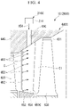
- FIG. 4 is a main portion sectional view showing the periphery of a wet region of a steam turbine in a fourth embodiment of the present invention.
- FIG. 5 is a sectional view showing a stator vane in the fourth embodiment of the present invention.
- FIG. 7 is a system diagram showing a combined cycle plant in a sixth embodiment of the present invention.
- the combined cycle plant 1 of the present embodiment includes, as shown in FIG. 1 , a gas turbine 10 , a first generator 15 that is configured to generate electric power due to driving of the gas turbine 10 , an exhaust heat recovery boiler 100 , a chimney 129 that discharges an exhaust gas from the exhaust heat recovery boiler 100 to the air, a flue 128 coupling the exhaust heat recovery boiler 100 to the chimney 129 , a steam turbine system 200 , and a water supply system 70 .
- the gas turbine 10 includes a compressor 11 that compresses air A, a combustor 20 that generates a combustion gas by burning a fuel in the air A compressed by the compressor 11 , and a turbine 30 that is driven by a high-temperature and high-pressure combustion gas.
- the steam turbine system 200 of the present embodiment includes a plurality of steam turbines 60 , a second generator 230 that generates electric power due to driving of the plurality of steam turbines 60 , a condenser 240 that returns steam exhausted from the steam turbines 60 to water, and a saturated steam generation portion 210 .
- the steam turbine system 200 of the present embodiment includes, as the steam turbines 60 , a high-pressure steam turbine 601 , an intermediate-pressure steam turbine 602 , and a low-pressure steam turbine 603 .
- a configuration of the steam turbines 60 of the present invention will be described in detail by exemplifying the low-pressure steam turbine 603 .
- the low-pressure steam turbine 603 is provided with a main flow path C through which a main steam flows.
- the main flow path C is an internal space of the low-pressure steam turbine 603 interposed between a steam inlet and a steam outlet.
- the main steam is superheated steam when flowing into the main flow path C from the steam inlet.
- the superheated steam is steam of which a temperature is a saturation temperature (100° C. at the atmospheric pressure) or higher.
- the main steam is subjected to a pressure reduction toward a downstream side from the steam inlet to the steam outlet, and thus expands.
- the main steam is brought into a dryness saturation state due to a reduction in the dryness to further expand, and thus becomes wet steam containing fine water droplets (drains).
- the wet steam is steam of which a temperature is a saturation temperature and the dryness is more than 0% and less than 100%.
- the low-pressure steam turbine 603 includes a steam turbine rotor 61 rotating about an axis, a steam turbine casing 64 covering the steam turbine rotor 61 , and a plurality of stator vane rows 65 provided on an inner circumferential surface of the steam turbine casing 64 .
- the plurality of stator vane rows 65 are arranged with gaps in an axis direction in which the axis extends.
- Each stator vane row 65 has a plurality of stator vanes 650 arranged in a circumferential direction centering on the axis.
- the steam turbine rotor 61 includes a rotor shaft 62 extending in the axis direction centering on the axis, and a plurality of rotor blade lows 63 fixed on an outer circumferential surface of the rotor shaft 62 .
- Each of the plurality of rotor blade lows 63 is disposed on the downstream side of any one of the stator vane rows 65 in the axis direction.
- Each rotor blade low 63 has a plurality of rotor blades 630 arranged in the circumferential direction centering on the axis.
- the rotor blades 630 and the stator vanes 650 are disposed in the main flow path C.
- a single rotor blade low 63 and the stator vane row 65 adjacent thereto on the rotor blade low 63 on the upstream side form a single “stage”.
- the low-pressure steam turbine 603 is provided with a plurality of stages (four stages in the present embodiment) of rotor blade lows 63 and the stator vane rows 65 .
- heights (lengths of the blades orthogonal to the rotor shaft 62 ) of the rotor blade 630 and the stator vane 650 are formed to increase toward the downstream side from the upstream side in the flow direction of the main flow path C.
- the high-pressure steam turbine 601 and the intermediate-pressure steam turbine 602 also have the same configuration.
- the steam turbine rotors of the high-pressure steam turbine 601 , the intermediate-pressure steam turbine 602 , and the low-pressure steam turbine 603 are coaxially disposed and are connected to each other, and thus form a single steam turbine rotor.
- the single steam turbine rotor is coupled to a rotor of the second generator 230 .
- the steam turbine rotor and the rotor of the second generator 230 are rotatably supported by second bearings 220 .
- the single second generator 230 is provided for a total of three steam turbines 60 including the high-pressure steam turbine 601 , the intermediate-pressure steam turbine 602 , and the low-pressure steam turbine 603 .
- a generator may be provided for each of the high-pressure steam turbine 601 , the intermediate-pressure steam turbine 602 , and the low-pressure steam turbine 603 .
- the condenser 240 of the present embodiment returns steam exhausted from the low-pressure steam turbine 603 to water.
- the saturated steam generation portion 210 generates a saturated steam from supplied water.
- the saturated steam generation portion 210 feeds the saturated steam into a wet region C 1 of the main flow path C in which the main steam is in a wet state.
- the saturated steam generation portion 210 of the present embodiment is supplied with water from the exhaust heat recovery boiler 100 .
- the saturated steam generation portion 210 generates the saturated steam from the supplied water.
- the wet state is a state in which the dryness of the main steam flowing through the main flow path C is more than 0% and less than 100%, and indicates that the main steam is wet steam.
- the pressure and the temperature of the flowing main steam are reduced toward the steam outlet from the steam inlet.
- the temperature in the main flow path C becomes a saturation temperature in the vicinity of the final stage, and the dryness is also less than 100%.
- a space of the main flow path C in which the temperature becomes a saturation temperature and the dryness is less than 100% is the wet region C 1 .
- the wet region C 1 of the present embodiment is, for example, a space in the vicinity of the final stage in the main flow path C of the low-pressure steam turbine 603 , and is a space of the main flow path C in which the pressure is lower than the atmospheric pressure and the dryness is less than 100% by several %.
- the saturated steam generation portion 210 supplies a saturated steam having a pressure corresponding to a pressure of a main steam in the main flow path C of the low-pressure steam turbine 603 at a position into which the main steam is fed. Therefore, the saturated steam generation portion 210 supplies a saturated steam having different pressures and temperatures according to positions into which the saturated steam is fed.
- the saturated steam generation portion 210 of the present embodiment includes a first flasher 211 , a second flasher 212 , a third flasher 213 , and a fourth flasher 214 . Therefore, the saturated steam generation portion 210 of the present embodiment generates flash steam over four-stage times.
- the first flasher 211 flashes water supplied from a low-pressure economizer 103 which will be described later, and thus generates a high-pressure saturated steam.
- the first flasher 211 supplies the low-pressure saturated steam to the upstream side of the wet region C 1 .
- the first flasher 211 supplies the high-pressure saturated steam to the steam inlet of the low-pressure steam turbine 603 . Therefore, the first flasher 211 generates, as the high-pressure saturated steam, a first saturated steam that has a saturation temperature at a pressure equal to that of the main steam supplied to the steam inlet of the low-pressure steam turbine 603 .
- the first saturated steam generated by the first flasher 211 has about 5.2 ata and 150° C.
- the first flasher 211 supplies first condensed water that is condensed water generated by flashing water from the low-pressure economizer 103 , to the second flasher 212 .
- the second flasher 212 flashes the first condensed water supplied from the first flasher 211 .
- the second flasher 212 generates a second saturated steam as a high-pressure saturated steam having a pressure lower than that of the first saturated steam.
- the second flasher 212 supplies the second saturated steam to the upstream region of the wet region C 1 .
- the second flasher 212 supplies the second saturated steam to a downstream region (for example, the second stage) of the region to which the first saturated steam is supplied from the first flasher 211 . Therefore, the second flasher 212 generates the second saturated steam having a saturation temperature at a pressure equal to that of the main steam in the downstream region of the steam inlet of the low-pressure steam turbine 603 .
- the second saturated steam generated by the second flasher 212 has about 2.7 ata and 130° C.
- the second flasher 212 supplies second condensed water that is condensed water generated by flashing the first condensed water, to the third flasher 213 .
- the third flasher 213 flashes the second condensed water supplied from the second flasher 212 .
- the third flasher 213 generates a third saturated steam as a high-pressure saturated steam having a pressure lower than that of the second saturated steam.
- the third flasher 213 supplies the third saturated steam to the upstream region of the wet region C 1 .
- the third flasher 213 supplies the third saturated steam to a downstream region (for example, the third stage) of the region to which the second saturated steam is supplied from the second flasher 212 in the main flow path C. Therefore, the third flasher 213 generates a third saturated steam having a saturation temperature at a pressure equal to that of the main steam in the downstream region of the region to which the second saturated steam is supplied in the main flow path C.
- the third saturated steam generated by the third flasher 213 has about 1.1 ata and 100° C.
- the third flasher 213 supplies third condensed water that is condensed water by flashing the second condensed water, to the fourth flasher 214 .
- the fourth flasher 214 flashes the third condensed water supplied from the third flasher 213 .
- the fourth flasher 214 generates a fourth saturated steam as a low-pressure saturated steam having a pressure lower than that of the third saturated steam.
- the fourth flasher 214 supplies the fourth saturated steam to the wet region C 1 .
- the fourth flasher 214 supplies the fourth saturated steam to a downstream region (the final stage in the present embodiment) of the region to which the third saturated steam is supplied from the third flasher 213 in the main flow path C. Therefore, the fourth flasher 214 generates the fourth saturated steam having a saturation temperature at a pressure equal to that of the main steam in the wet region C 1 .
- the fourth saturated steam generated by the fourth flasher 214 has about 0.4 ata and 75° C.
- the fourth flasher 214 feeds fourth condensed water to the low-pressure economizer 103 along with water supplied to the low-pressure economizer 103 from a low-temperature heat exchanger 102 which will be described later.
- the fourth condensed water is condensed water generated by flashing the third condensed water.
- the water supply system 70 feeds water in the condenser (supply water source) 240 to the exhaust heat recovery boiler 100 as supply water.
- the water supply system 70 supplies water having a temperature lower than a dew point temperature of an exhaust gas exhausted from the exhaust heat recovery boiler 100 .
- the water supply system 70 includes a supplied water line 71 coupling the condenser 240 to the exhaust heat recovery boiler 100 , and a water supply pump 79 feeding water in the condenser 240 to the exhaust heat recovery boiler 100 .
- the supplied water line 71 couples the condenser 240 to the low-temperature heat exchanger 102 which will be described later.
- the supplied water line 71 is provided with the water supply pump 79 .
- the exhaust heat recovery boiler 100 includes a boiler outer frame 101 , the low-temperature heat exchanger 102 , the low-pressure economizer 103 , a low-pressure evaporator 104 , a low-pressure superheater 105 , an intermediate-pressure reheater 106 , a high-pressure economizer 107 , a high-pressure evaporator 108 , and a high-pressure superheater 109 .
- the boiler outer frame 101 is coupled to an exhaust port of the turbine 30 and the flue 128 .
- a combustion gas having rotated the gas turbine rotor 13 flows into the boiler outer frame 101 as an exhaust gas.
- the exhaust gas passes through the boiler outer frame 101 , and is discharged to the air through the flue 128 and the chimney 129 .
- the chimney 129 side of the boiler outer frame 101 is a downstream side of a flow of the exhaust gas, and the turbine 30 side opposite thereto is an upstream side.
- the low-pressure economizer 103 the low-pressure evaporator 104 , the low-pressure superheater 105 , the intermediate-pressure reheater 106 , the high-pressure economizer 107 , the high-pressure evaporator 108 , and the high-pressure superheater 109 are provided inside the boiler outer frame 101 .
- the low-pressure economizer 103 , the low-pressure evaporator 104 , the low-pressure superheater 105 , the high-pressure economizer 107 , the high-pressure evaporator 108 , the high-pressure superheater 109 , and the intermediate-pressure reheater 106 are arranged in this order from the downstream side of the exhaust gas to the upstream side.
- the low-temperature heat exchanger 102 is disposed in the flue 128 .
- the low-temperature heat exchanger 102 may be disposed outside the boiler outer frame 101 and on the downstream side of the low-pressure economizer 103 .
- the low-temperature heat exchanger 102 may be omitted.
- the low-temperature heat exchanger 102 subjects the exhaust gas having passed through the flue 128 and the supplied water to heat exchange, and thus heats the supplied water and cools the exhaust gas.
- the low-temperature heat exchanger 102 feeds the heated supplied water to the low-pressure economizer 103 .
- the low-temperature heat exchanger 102 and the low-pressure economizer 103 are coupled to a first heated water line 111 .
- the heated supplied water flows into the low-pressure economizer 103 .
- the exhaust gas having passed through the low-pressure evaporator 104 flows into the low-pressure economizer 103 .
- the low-pressure economizer 103 subjects the exhaust gas and the supplied water heated by the low-temperature heat exchanger 102 to heat exchange, and thus heats the supplied water so as to generate low-pressure heated water.
- the low-pressure economizer 103 feeds the generated low-pressure heated water to the low-pressure evaporator 104 and the high-pressure economizer 107 .
- the low-pressure economizer 103 and the low-pressure evaporator 104 are coupled to each other via a second heated water line 112 .
- the second heated water line 112 is provided with a first evaporator supplied water valve 112 a .
- the first evaporator supplied water valve 112 a depressurizes the low-pressure heated water.
- the low-pressure economizer 103 and the high-pressure economizer 107 are coupled to each other via a third heated water line 113 .
- the third heated water line 113 is provided with a high-pressure pump 115 .
- the high-pressure pump 115 pressurizes the low-pressure heated water so as to generate high-pressure heated water.
- the high-pressure pump 115 feeds the generated high-pressure heated water to the high-pressure economizer 107 .
- the low-pressure heated water flows into the low-pressure evaporator 104 .
- the exhaust gas having passed through the low-pressure superheater 105 flows into the low-pressure evaporator 104 .
- the low-pressure evaporator 104 subjects the low-pressure heated water heated by the low-pressure economizer 103 and the exhaust gas to heat exchange, and thus heats the low-pressure heated water so as to generate a low-pressure steam.
- the low-pressure evaporator 104 feeds the generated low-pressure steam to the low-pressure superheater 105 .
- the low-pressure evaporator 104 and the low-pressure superheater 105 are coupled to each other via a first steam line 121 .
- the low-pressure steam flows into the low-pressure superheater 105 .
- the exhaust gas having passed through the high-pressure economizer 107 flows into the low-pressure superheater 105 .
- the low-pressure superheater 105 subjects the low-pressure steam and the exhaust gas to heat exchange, and thus superheats the low-pressure steam.
- the low-pressure superheater 105 feeds the superheated low-pressure steam to the low-pressure steam turbine 603 as a low-pressure superheated steam.
- the high-pressure heated water flows into the high-pressure economizer 107 .
- the exhaust gas having passed through the high-pressure evaporator 108 flows into the high-pressure economizer 107 .
- the high-pressure economizer 107 subjects the high-pressure heated water and the exhaust gas to heat exchange, and thus further heats the high-pressure heated water.
- the high-pressure economizer 107 feeds the heated high-pressure heated water to the high-pressure evaporator 108 .
- the high-pressure economizer 107 and the high-pressure evaporator 108 are coupled to each other via a fourth heated water line 114 .
- the fourth heated water line 114 is provided with a second evaporator supplied water valve 114 a .
- the second evaporator supplied water valve 114 a depressurizes the heated high-pressure heated water.
- the heated high-pressure heated water flows into the high-pressure evaporator 108 .
- the exhaust gas having passed through the high-pressure superheater 109 flows into the high-pressure evaporator 108 .
- the high-pressure evaporator 108 subjects the high-pressure heated water heated by the high-pressure economizer 107 and the exhaust gas to heat exchange so as to heat the high-pressure heated water, and thus generates a high-pressure steam.
- the high-pressure evaporator 108 feeds the generated high-pressure steam to the high-pressure superheater 109 .
- the high-pressure evaporator 108 and the high-pressure superheater 109 are coupled to each other via a second steam line 122 .
- the high-pressure steam flows into the high-pressure superheater 109 .
- the exhaust gas having passed through the intermediate-pressure reheater 106 flows into the high-pressure superheater 109 .
- the high-pressure superheater 109 subjects the high-pressure steam and the exhaust gas to heat exchange, and thus superheats the high-pressure steam.
- the high-pressure superheater 109 feeds the superheated high-pressure steam to the high-pressure steam turbine 601 as high-pressure superheated steam.
- the main steam exhausted from the high-pressure steam turbine 601 flows into the intermediate-pressure reheater 106 .
- the exhaust gas exhausted from the turbine 30 flows into the intermediate-pressure reheater 106 .
- the intermediate-pressure reheater 106 subjects the main steam exhausted from the high-pressure steam turbine 601 and the exhaust gas to heat exchange so as to superheat the main steam, and feeds the superheated main steam to the intermediate-pressure steam turbine 602 as an intermediate-pressure superheated steam.
- the high-pressure superheater 109 and the steam inlet of the high-pressure steam turbine 601 are coupled to a high-pressure steam line 131 .
- the steam outlet of the high-pressure steam turbine 601 and the intermediate-pressure reheater 106 are coupled to a high-pressure exhaust air line 132 .
- the intermediate-pressure reheater 106 and the steam inlet of the intermediate-pressure steam turbine 602 are coupled to each other via an intermediate-pressure steam line 133 .
- the steam outlet of the intermediate-pressure steam turbine 602 and the steam inlet of the low-pressure steam turbine 603 are coupled to each other via an intermediate-pressure exhaust air line 134 .
- the intermediate-pressure exhaust air line 134 and the low-pressure superheater 105 via a low-pressure steam line 135 .
- the steam outlet of the low-pressure steam turbine 603 and the condenser 240 are coupled to each other via a low-pressure exhaust air line 136 .
- the low-pressure economizer 103 and the first flasher 211 are coupled to each other via a first flasher supplied water line 141 .
- the first flasher supplied water line 141 of the present embodiment is coupled to the second heated water line 112 , and is indirectly coupled to the low-pressure economizer 103 .
- the first flasher supplied water line 141 is provided with a first flasher supplied water valve 141 a that controls a state of the supply of water to the first flasher 211 .
- the first flasher 211 and the low-pressure steam turbine 603 are coupled to each other via a first saturated steam line 151 .
- the first saturated steam line 151 is coupled to the intermediate-pressure exhaust air line 134 on the downstream side of a connection portion between the intermediate-pressure exhaust air line 134 and the low-pressure steam line 135 .
- the first flasher 211 and the second flasher 212 are coupled to each other via a second flasher supplied water line 142 .
- the second flasher supplied water line 142 is provided with a second flasher supplied water valve 142 a that controls a state of the supply of water to the second flasher 212 .
- the second flasher 212 and the low-pressure steam turbine 603 are coupled to each other via a second saturated steam line 152 .
- the second saturated steam line 152 is coupled to communicate with the main flow path C of the low-pressure steam turbine 603 in the vicinity of the second stage.
- the second saturated steam line 152 of the first embodiment is coupled to communicate with the main flow path C on the upstream side of the rotor blade 630 .
- the second flasher 212 and the third flasher 213 are coupled to each other via a third flasher supplied water line 143 .
- the third flasher supplied water line 143 is provided with a third flasher supplied water valve 143 a that controls a state of the supply of water to the third flasher 213 .
- the third flasher 213 and the low-pressure steam turbine 603 are coupled to each other via a third saturated steam line 153 .
- the third saturated steam line 153 is coupled to communicate with the main flow path C of the low-pressure steam turbine 603 in the vicinity of the third stage.
- the third saturated steam line 153 of the first embodiment is coupled to communicate with the main flow path C on the upstream side of the rotor blade 630 .
- the third flasher 213 and the fourth flasher 214 are coupled to each other via a fourth flasher supplied water line 144 .
- the fourth flasher supplied water line 144 is provided with a fourth flasher supplied water valve 144 a that controls a state of the supply of water to the fourth flasher 214 .
- the fourth flasher 214 and the low-pressure steam turbine 603 are coupled to each other via a fourth saturated steam line 154 .
- the fourth saturated steam line 154 is coupled to communicate with the main flow path C of the low-pressure steam turbine 603 in the vicinity of the final stage.
- the fourth saturated steam line 154 of the first embodiment is coupled to communicate with the main flow path C on the upstream side of the rotor blade 630 .
- the fourth flasher 214 and the low-pressure economizer 103 are coupled to each other via a condensed water exhaust line 155 .
- the condensed water exhaust line 155 is coupled to the first heated water line 111 , and is thus indirectly coupled to the low-pressure economizer 103 .
- the condensed water exhaust line 155 is provided with a condensed water exhaust pump 155 a.
- the compressor 11 of the gas turbine 10 compresses the air A, and supplies the compressed air A to the combustor 20 .
- a fuel is also supplied to the combustor 20 .
- the fuel is burnt in the compressed air A, and thus a high-temperature and high-pressure combustion gas is generated.
- the combustion gas is fed to a combustion gas flow path in the turbine 30 from the combustor 20 , and rotates the gas turbine rotor 13 .
- the first generator 15 coupled to the gas turbine 10 generates electric power due to the rotation of the gas turbine rotor 13 .
- the combustion gas having rotated the gas turbine rotor 13 is exhausted as an exhaust gas from the turbine 30 , and is discharged to the air from the chimney 129 through the exhaust heat recovery boiler 100 and the flue 128 .
- the exhaust heat recovery boiler 100 recovers heat contained in the exhaust gas when the exhaust gas from the turbine 30 passes therethrough.
- water is supplied to the low-temperature heat exchanger 102 on the downstream side (the chimney 129 side) via the supplied water line 71 .
- the supplied water is water into which steam exhausted from the steam outlet of the low-pressure steam turbine 603 is converted by the condenser 240 .
- the low-temperature heat exchanger 102 subjects the supplied water and the exhaust gas to heat exchange, and thus heats the supplied water.
- the supplied water heated by the low-temperature heat exchanger 102 is fed to the low-pressure economizer 103 via the first heated water line 111 .
- the low-pressure economizer 103 subjects the supplied water and the exhaust gas to heat exchange so as to further heat the supplied water, and thus generates low-pressure heated water.
- the pressure of the low-pressure heated water is maintained to be higher than a drum pressure of the low-pressure evaporator 104 in order to prevent the occurrence of boiling in the low-pressure economizer 103 .
- Part of the low-pressure heated water generated by the low-pressure economizer 103 is depressurized in the first evaporator supplied water valve 112 a provided at the second heated water line 112 , and is then fed to the low-pressure evaporator 104 .
- the low-pressure evaporator 104 subjects the low-pressure heated water and the exhaust gas to heat exchange so as to heat the low-pressure heated water, and thus generates a low-pressure steam.
- the generated low-pressure steam is fed to the low-pressure superheater 105 via the first steam line 121 .
- the low-pressure superheater 105 subjects the low-pressure steam and the exhaust gas to heat exchange so as to superheat the low-pressure steam, and thus generates a low-pressure superheated steam.
- the generates low-pressure superheated steam is fed to the steam inlet of the low-pressure steam turbine 603 from the low-pressure steam line 135 via the intermediate-pressure exhaust air line 134 .
- the low-pressure heated water flowing into the third heated water line 113 is pressurized in the high-pressure pump 115 , and thus becomes high-pressure heated water.
- the high-pressure heated water is fed to the high-pressure economizer 107 via the third heated water line 113 .
- the high-pressure economizer 107 subjects the high-pressure heated water and the exhaust gas to heat exchange so as to further heat the high-pressure heated water.
- the high-pressure heated water heated by the high-pressure economizer 107 is fed to the high-pressure evaporator 108 via the fourth heated water line 114 .
- the pressure of the heated high-pressure heated water is maintained to be higher than a drum pressure of the high-pressure evaporator 108 in order to prevent the occurrence of boiling in the high-pressure economizer 107 .
- the high-pressure heated water heated by the high-pressure economizer 107 is depressurized in the second evaporator supplied water valve 114 a provided at the fourth heated water line 114 , and is then fed to the high-pressure evaporator 108 .
- the high-pressure evaporator 108 subjects the high-pressure heated water heated by the high-pressure economizer 107 and the exhaust gas to heat exchange so as to heat the high-pressure heated water, and thus generates a high-pressure steam.
- the generated high-pressure steam is fed to the high-pressure superheater 109 via the second steam line 122 .
- the high-pressure superheater 109 subjects the high-pressure steam and the exhaust gas to heat exchange so as to superheat the high-pressure steam, and thus generates a high-pressure superheated steam.
- the generated high-pressure superheated steam is fed to the steam inlet of the high-pressure steam turbine 601 via the high-pressure steam line 131 .
- the high-pressure steam turbine 601 is driven with the high-pressure superheated steam as a main steam.
- the high-pressure superheated steam is subjected to reductions of both of pressure and temperature during flowing through the high-pressure steam turbine 601 .
- the high-pressure superheated steam exhausted from the high-pressure steam turbine 601 flows into the intermediate-pressure reheater 106 via the high-pressure exhaust air line 132 .
- the intermediate-pressure reheater 106 reheats the high-pressure superheated steam of which the pressure and temperature are reduced with the exhaust gas. Consequently, intermediate-pressure superheated steam having a pressure lower than the pressure of the high-pressure superheated steam generated by the high-pressure superheater 109 is generated.
- the temperature of the generated intermediate-pressure superheated steam (reheated steam) is equal to or higher than that of the high-pressure superheated steam. This is because, since the pressure of the intermediate-pressure superheated steam is lower than that of the high-pressure steam, it is easier to increase the temperature of the high-pressure heated steam than to increase the pressure of the intermediate-pressure superheated steam due to a restriction in the durability of facilities such as a pipe or a heat transfer piper.
- the intermediate-pressure reheater 106 is located further toward the upstream side than the high-pressure superheater 109 when viewed from the flow direction of the exhaust gas, and thus the temperature of the intermediate-pressure superheated steam can be made equal to or higher than that of the high-pressure superheated steam.
- the intermediate-pressure superheated steam is fed to the steam inlet of the intermediate-pressure steam turbine 602 via the intermediate-pressure steam line 133 . Consequently, the intermediate-pressure steam turbine 602 is driven with the intermediate-pressure superheated steam as a main steam.
- the intermediate-pressure superheated steam is subjected to reductions of both of pressure and temperature during flowing through the intermediate-pressure steam turbine 602 , and thus becomes the same extent as the low-pressure superheated steam.
- the intermediate-pressure superheated steam exhausted from the intermediate-pressure steam turbine 602 that is, an intermediate-pressure exhaust steam is fed to the steam inlet of the low-pressure steam turbine 603 via the intermediate-pressure exhaust air line 134 .
- the intermediate-pressure exhaust steam exhausted from the intermediate-pressure steam turbine 602 , the low-pressure superheated steam fed from the low-pressure superheater 105 , and the first saturated steam flow into the steam inlet of the low-pressure steam turbine 603 .
- the low-pressure steam turbine 603 is driven with a mixture of the steams as a main steam.
- the main steam is in a superheated state in the inlet of the low-pressure steam turbine 603 .
- First condensed water generated due to generation of the first saturated steam flows into the second flasher supplied water line 142 from the first flasher 211 .
- the first condensed water flowing into the second flasher supplied water line 142 is fed to the second flasher 212 via the second flasher supplied water valve 142 a .
- a second saturated steam is generated in the second flasher 212 .
- the second saturated steam is supplied to the second stage of the low-pressure steam turbine 603 via the second saturated steam line 152 .
- the main steam flowing through the vicinity of the second stage of the main flow path C is mixed with the second saturated steam.
- Second condensed water generated due to generation of the second saturated steam flows into the third flasher supplied water line 143 from the second flasher 212 .
- the second condensed water flowing into the third flasher supplied water line 143 is fed to the third flasher 213 via the third flasher supplied water valve 143 a .
- a third saturated steam is generated in the third flasher 213 .
- the third saturated steam is supplied to the third stage of the low-pressure steam turbine 603 via the third saturated steam line 153 .
- the main steam flowing through the vicinity of the third stage of the main flow path C is mixed with the third saturated steam.
- Third condensed water generated due to generation of the third saturated steam flows into the fourth flasher supplied water line 144 from the third flasher 213 .
- the third condensed water flowing into the fourth flasher supplied water line 144 is fed to the fourth flasher 214 via the fourth flasher supplied water valve 144 a .
- a fourth saturated steam is generated in the fourth flasher 214 .
- the fourth saturated steam is supplied to the wet region C 1 in the vicinity of the final stage of the low-pressure steam turbine 603 via the fourth saturated steam line 154 .
- the main steam flowing through the wet region C 1 of the main flow path C is mixed with the fourth saturated steam.
- Fourth condensed water generated due to generation of the fourth saturated steam flows into the condensed water exhaust line 155 from the fourth flasher 214 .
- the fourth condensed water flowing into the condensed water exhaust line 155 flows into the first heated water line 111 via the condensed water exhaust pump 155 a .
- the fourth condensed water is fed to the low-pressure economizer 103 along with the supplied water heated by the low-temperature heat exchanger 102 .
- the main steam exhausted from the steam outlet of the low-pressure steam turbine 603 flows into the condenser 240 via the low-pressure exhaust air line 136 .
- the steam is cooled and condensed in the condenser 240 , and thus becomes water.
- the water is fed to the low-temperature heat exchanger 102 again as supplied water via the supplied water line 71 .
- the fourth saturated steam is supplied to the wet region C 1 of the main flow path C of the low-pressure steam turbine 603 from the fourth flasher 214 .
- the fourth saturated steam is fed into the wet region C 1 , and thus the fourth saturated steam is mixed with the main steam in the wet region C 1 .
- the main steam is subjected to a reduction of the dryness to become a wet steam, but is mixed with the fourth saturated steam to be subjected to an increase of the dryness, and thus a heat quantity (entropy) thereof is increased.
- heat with a temperature in a level corresponding to a saturation temperature at each temperature is effectively recovered and used.
- the first saturated steam, the second saturated steam, and the third saturated steam having pressures higher than a pressure of the fourth saturated steam are supplied to the region in which the main steam is in a superheated state and which is an upstream region of the wet region C 1 .
- a heat quantity (entropy) of the saturated steam is lower than a heat quantity (entropy) of a superheated steam.
- the saturated steam is supplied to the upstream region of the wet region C 1 , that is, a superheated region in which the main steam is a superheated steam
- the heat quantity (entropy) of the main steam is reduced in each location where steam mixing occurs, and thus the dryness is also reduced in the downstream wet region C 1 .
- this causes erosion or a reduction of efficiency of the steam turbine.
- an increase of the dryness in the wet region C 1 due to mixing with the fourth saturated steam cancels out a reduction of the dryness in the wet region C 1 due to mixing with the first saturated steam, the second saturated steam, and the third saturated steam.
- the saturated steam generation portion 210 of the present embodiment has the multi-stage flasher that gradually reduces pressures in an order of the first flasher 211 , the second flasher 212 , the third flasher 213 , and the fourth flasher 214 , and generates a flash steam over a plurality of times.
- saturated steams having different pressures and temperatures can be fed into the low-pressure steam turbine 603 . Therefore, a saturated steam corresponding to a pressure of the main steam flowing through the main flow path C can be supplied to the low-pressure steam turbine 603 .
- the first saturated steam having a relatively high pressure is generated from the low-pressure heated water having a high temperature, and a saturated steam having a pressure lower than that of the first saturated steam is generated from remaining condensed water having a reduced temperature.
- saturated steams are sequentially generated while reducing a pressure and a temperature, and thus a saturated steam having as high pressure and temperature as possible can be obtained to be supplied to the steam turbine.
- Flash steams are generated over a plurality of times while reducing a pressure, and thus supplied water can be used until a temperature of the water becomes low.
- heat of the water when a saturated steam is generated can be recovered up to a low temperature, and thus it is possible to improve the efficiency of the system while increasing an output of the steam turbine.
- the first saturated steam can be obtained by using the low-pressure heated water that has a high temperature and is heated by using exhaust gas in the exhaust heat recovery boiler 100 .
- the second saturated steam can be obtained by using the first condensed water generated after the first saturated steam is generated.
- the third saturated steam and the fourth saturated steam can be obtained. Since saturated steams can be obtained from the low-pressure heated water having a high temperature over a plurality of stages, saturated steams corresponding to different pressure and temperatures can be easily generated.
- the low-pressure heated water generated by the low-pressure economizer 103 in the exhaust heat recovery boiler 100 is supplied to the first flasher 211 .
- heat of an exhaust gas from the gas turbine 10 can be sufficiently recovered by the exhaust heat recovery boiler 100 , and then high-temperature water can be obtained by using the heat of the exhaust gas.
- the low-pressure superheated water generated by the low-pressure economizer 103 is generated as saturated steams over a plurality of times by the saturated steam generation portion 210 , and the saturated steams are supplied to the low-pressure steam turbine 603 . Consequently, heat of the exhaust gas is recovered as an output of the low-pressure steam turbine 603 . Therefore, it is possible to more effectively use heat contained an exhaust gas.
- the fourth condensed water generated due to generation of the fourth saturated steam in the fourth flasher 214 is fed to the first heated water line 111 via the condensed water exhaust line 155 .
- the fourth condensed water is fed to the low-pressure economizer 103 along with supplied water heated by the low-temperature heat exchanger 102 . Therefore, it is possible to prevent that the fourth condensed water is directly returned to the low-temperature heat exchanger 102 that warms the supplied water by using heat of an exhaust gas having the lowest temperature, and thus a temperature of the supplied water is increased.
- a combined cycle plant 1 A of the second embodiment is different from that of the first embodiment in that, for example, a supplied water heater 78 heating supplied water is further provided, or the low-temperature heat exchanger 102 is not provided. Therefore, in a description of the second embodiment, the same portion as that in the first embodiment will be given the same reference numeral, and a description thereof will not be repeated.
- the combined cycle plant 1 A of the second embodiment includes an intake air cooler 40 , a cooling air cooler (gas turbine cooler) 50 , a first generator cooler 16 , a first lubricant cooler 17 , a second generator cooler 66 , and a second lubricant cooler 67 .
- the intake air cooler 40 subjects a first cooling medium cooling the air A sucked by the compressor 11 and supplied water to heat exchange, and thus cools the first cooling medium and heats the supplied water.
- the intake air cooler 40 includes an intake air heat exchanger 41 and an intake air refrigerator 42 .
- the intake air heat exchanger 41 subjects the air A sucked by the compressor 11 and the first cooling medium to heat exchange, and thus cools the air A and heats the first cooling medium.
- the intake air refrigerator 42 moves heat of the first cooling medium heated by the intake air heat exchanger 41 to the supplied water so as to heat the supplied water, and also cools the first cooling medium.
- the cooling air cooler 50 subjects a second cooling medium cooling a constituent component of the gas turbine 10 and supplied water to heat exchange, and thus cools the second cooling medium and heats the supplied water.
- the cooling air cooler 50 cools air in order to a high-temperature component in contact with a high-temperature combustion gas among components forming the gas turbine 10 . Therefore, the second cooling medium in the cooling air cooler 50 is air such as compressed air or extracted air.
- high-temperature components in contact with a high-temperature combustion gas are, for example, a tail pipe of the combustor 20 , and a stator vane and a rotor blade of the turbine 30 .
- the cooling air cooler 50 has a first air cooler 51 , a second air cooler 52 , and a third air cooler 53 .
- the first air cooler 51 cools compressed air that is compressed by the compressor 11 , and thus generates combustor cooling air for cooling a computation of the combustor 20 such as the tail pipe.
- the first air cooler 51 feeds the generated combustor cooling air to the combustor 20 .
- the second air cooler 52 cools the compressed air that is compressed by the compressor 11 , and thus generates, for example, front-stage cooling air for cooling a stator vane and a rotor blade in a front stage of the turbine 30 .
- the second air cooler 52 feeds the generated front-stage cooling air to the front stage of the turbine 30 .
- the third air cooler 53 cools extracted air that is extracted from an intermediate stage of the compressor 11 , and thus generates, for example, rear-stage cooling air for cooling a stator vane and a rotor blade in a rear stage of the turbine 30 .
- the third air cooler 53 feeds the generated rear-stage cooling air to the rear stage of the turbine 30 .
- the first generator cooler 16 subjects a third cooling medium cooling a constituent component of the first generator 15 and supplied water to heat exchange, and thus cools the third cooling medium and heats the supplied water.
- the first generator cooler 16 cools the rotor or the stator of the first generator 15 with the third cooling medium such as hydrogen.
- the first generator cooler 16 is provided in the first generator 15 .
- the first generator cooler 16 cools the cooling medium through heat exchange with the supplied water.
- the first lubricant cooler 17 subjects a lubricant from the first bearings 14 and supplied water to heat exchange so as to cool the lubricant and to heat the supplied water, and returns the cooled lubricant to the first bearings 14 .
- the first lubricant cooler 17 subjects the lubricant from the first bearings 14 and supplied water to heat exchange so as to cool the lubricant.
- the first lubricant cooler 17 returns the cooled lubricant to the first bearings 14 .
- the second generator cooler 66 subjects the third cooling medium cooling a constituent component of the second generator 230 and supplied water to heat exchange, and thus cools the third cooling medium and heats the supplied water.
- the second generator cooler 66 cools the rotor or the stator of the second generator 230 with the third cooling medium such as hydrogen.
- the second generator cooler 66 is provided in the second generator 230 .
- the second generator cooler 66 cools the cooling medium through heat exchange with the supplied water.
- the second lubricant cooler 67 subjects a lubricant from the second bearings 220 and supplied water to heat exchange so as to cool the lubricant and to heat the supplied water, and returns the cooled lubricant to the second bearings 220 .
- the second lubricant cooler 67 subjects the lubricant from the second bearings 220 and supplied water to heat exchange so as to cool the lubricant.
- the second lubricant cooler 67 returns the cooled lubricant to the second bearings 220 .
- a water supply system 70 A of the second embodiment includes a supplied water line 71 A, a water supply pump 79 , and a supplied water heater 78 heating supplied water flowing through the supplied water line 71 A.
- the supplied water line 71 A of the second embodiment includes a first supplied water line 72 , a second supplied water line 73 , a third supplied water line 74 , and a fourth supplied water line 75 .
- the first supplied water line 72 couples the condenser 240 to the low-pressure economizer 103 of the exhaust heat recovery boiler 100 .
- the first supplied water line 72 is provided with the water supply pump 79 .
- the first supplied water line 72 is provided with the intake air refrigerator 42 , a sub-cooler 77 , the first generator cooler 16 , the first lubricant cooler 17 , the third air cooler 53 , and the second air cooler 52 in this order on a downstream side of the water supply pump 79 in a flow of supplied water.
- the intake air refrigerator 42 heat of a cooling medium heated through heat exchange with the air A sucked by the compressor 11 moves to supplied water flowing through the first supplied water line 72 .
- the sub-cooler 77 cools the supplied water heated by the intake air refrigerator 42 .
- the first generator cooler 16 subjects the supplied water cooled by the sub-cooler 77 and the cooling medium cooling the first generator 15 to heat exchange, and thus cools the cooling medium and heats the supplied water.
- the first lubricant cooler 17 subjects the supplied water heated by the first generator cooler 16 and the lubricant from the first bearings 14 to heat exchange, and thus cools the lubricant and heats the supplied water.
- the third air cooler 53 subjects the supplied water heated by the first lubricant cooler 17 and the extracted air that is extracted from the intermediate stage of the compressor 11 to heat exchange, and thus cools the extracted air and heats the supplied water.
- the second air cooler 52 subjects the supplied water heated by the third air cooler 53 and compressed air that is compressed by the compressor 11 to heat exchange, and thus cools the compressed air and heats the supplied water.
- the second supplied water line 73 branches from the first supplied water line 72 between the intake air refrigerator 42 and the sub-cooler 77 .
- the second supplied water line 73 is coupled to the low-pressure exhaust air line 136 . Therefore, the second supplied water line 73 returns part of the supplied water heated by the intake air refrigerator 42 to the condenser 240 again.
- the third supplied water line 74 branches from the first supplied water line 72 between the third air cooler 53 and the second air cooler 52 .
- the third supplied water line 74 is joined to the first supplied water line 72 again on a downstream side of the position where the second air cooler 52 is disposed in the first supplied water line 72 in the flow of supplied water.
- the third supplied water line 74 is provided with the first air cooler 51 . Therefore, the first air cooler 51 subjects supplied water flowing through the third supplied water line 74 and compressed air that is compressed by the compressor 11 to heat exchange, and thus cools the compressed air and heats the supplied water.
- the fourth supplied water line 75 branches from the first supplied water line 72 between the sub-cooler 77 and the first generator cooler 16 .
- the fourth supplied water line 75 is joined to the third supplied water line 74 between the first lubricant cooler 17 and the third air cooler 53 .
- the fourth supplied water line 75 is provided with the second generator cooler 66 and the second lubricant cooler 67 . Therefore, the second generator cooler 66 subjects supplied water flowing through the fourth supplied water line 75 and a cooling medium cooling the second generator 230 to heat exchange, and thus cools the cooling medium and heats the supplied water.
- the second lubricant cooler 67 subjects the supplied water heated by the second generator cooler 66 and the lubricant from the second bearings 220 to heat exchange, and thus cools the lubricant and heats the supplied water.
- the supplied water heater 78 heats supplied water that is water flowing through the supplied water line 71 A.
- the supplied water heater 78 is provided at the supplied water line 71 A.
- the supplied water heater 78 of the present embodiment is configured with the intake air cooler 40 , the first generator cooler 16 , the first lubricant cooler 17 , the second generator cooler 66 , the second lubricant cooler 67 , and the cooling air cooler 50 .
- the supplied water heater 78 is not limited to a configuration including all of the intake air cooler 40 , the first generator cooler 16 , the first lubricant cooler 17 , the second generator cooler 66 , the second lubricant cooler 67 , and the cooling air cooler 50 .
- the supplied water heater 78 may include at least one thereof.
- the second saturated steam line 152 of the second embodiment is coupled to communicate with the main flow path C on the downstream side of the rotor blade 630 and on the upstream side of the stator vane 650 .
- the second saturated steam line 152 is not limited to one of communication with the main flow path C on the upstream side of the rotor blade 630 as in the first embodiment and communication with the main flow path C on the downstream side of the rotor blade 630 as in the second embodiment.
- the second saturated steam line 152 may be coupled to communicate with the main flow path C on the upstream side of the stator vane 650 in the vicinity of the second stage.
- the third saturated steam line 153 of the second embodiment is coupled to communicate with the main flow path C on the downstream side of the rotor blade 630 and on the upstream side of the stator vane 650 .
- the third saturated steam line 153 is not limited to one of communication with the main flow path C on the upstream side of the rotor blade 630 as in the first embodiment and communication with the main flow path C on the downstream side of the rotor blade 630 as in the second embodiment.
- the third saturated steam line 153 may be coupled to communicate with the main flow path C on the upstream side of the stator vane 650 in the vicinity of the third stage.
- the fourth saturated steam line 154 of the second embodiment is coupled to communicate with the main flow path C on the downstream side of the rotor blade 630 and on the upstream side of the stator vane 650 .
- the fourth saturated steam line 154 is not limited to one of communication with the main flow path C on the upstream side of the rotor blade 630 as in the first embodiment and communication with the main flow path C on the downstream side of the rotor blade 630 as in the second embodiment.
- the fourth saturated steam line 154 may be coupled to communicate with the main flow path C in the wet region C 1 on the upstream side of the stator vane 650 of the wet region C 1 .
- the main steam exhausted from the low-pressure steam turbine 603 flows into the condenser 240 .
- the steam is cooled and condensed in the condenser 240 , and thus becomes water.
- the water generated by the condenser 240 is pumped as supplied water through the supplied water line 71 A by the water supply pump 79 .
- the supplied water flowing through the supplied water line 71 A is heated by the supplied water heater 78 during flowing through the supplied water line 71 A.
- the supplied water is heated by the intake air cooler 40 , the first generator cooler 16 , the first lubricant cooler 17 , the second generator cooler 66 , the second lubricant cooler 67 , the first air cooler 51 , the second air cooler 52 , and the third air cooler 53 .
- the supplied water from the condenser 240 flows through the first supplied water line 72 and then flows into the intake air refrigerator 42 .
- a mass flow rate of the air A sucked by the compressor 11 is reduced. Therefore, in a case where the temperature of the air A sucked by the compressor 11 increases, a gas turbine output is reduced. Therefore, in the present embodiment, heat of the air A sucked by the compressor 11 is moved to supplied water by the intake air cooler 40 , and thus the supplied water is heated, and the air A is cooled.
- the supplied water flowing into the second supplied water line 73 is fed to the condenser 240 again via the low-pressure exhaust air line 136 .
- Part of the supplied water heated by the intake air cooler 40 further flows through the first supplied water line 72 , and is then fed to the sub-cooler 77 .
- the supplied water fed to the sub-cooler 77 is cooled, and is fed to the first generator cooler 16 .
- the supplied water fed to the first generator cooler 16 moves the heat of the third cooling medium to the supplied water, and thus heats the supplied water and cools the third cooling medium.
- the supplied water heated by the first generator cooler 16 is fed to the first lubricant cooler 17 .
- the supplied water fed to the first lubricant cooler 17 moves heat of a lubricant to the supplied water, and thus heats the supplied water and cools the lubricant.
- Part of the supplied water heated by the first lubricant cooler 17 further flows through the first supplied water line 72 , and is then fed to the third air cooler 53 .
- the supplied water fed to the third air cooler 53 moves heat of extracted air to the supplied water, and thus heats the supplied water and cools the extracted air.
- the supplied water heated by the third air cooler 53 is fed to the second air cooler 52 .
- the supplied water fed to the second air cooler 52 moves heat of compressed air to the supplied water, and thus heats the supplied water and cools the compressed air.
- the supplied water heated by the second air cooler 52 further flows through the first supplied water line 72 to be joined to the fourth condensed water, and is then fed to the low-pressure economizer 103 .
- the supplied water flowing into the fourth supplied water line 75 is fed to the second generator cooler 66 .
- the supplied water fed to the second generator cooler 66 moves heat of the third cooling medium to the supplied water, and thus heats the supplied water and cools the third cooling medium.
- the supplied water heated by the second generator cooler 66 is fed to the second lubricant cooler 67 .
- the supplied water fed to the second lubricant cooler 67 moves heat of a lubricant to the supplied water, and thus heats the supplied water and cools the lubricant.
- the supplied water heated by the second generator cooler 66 and the second lubricant cooler 67 is joined to the first supplied water line 72 again, to be joined to the supplied water heated by the first lubricant cooler 17 , and is then fed to the third air cooler 53 .
- Part of the supplied water heated by the third air cooler 53 is fed to the first air cooler 51 via the third supplied water line 74 .
- the supplied water fed to the first air cooler 51 moves heat of compressed air to the supplied water, and thus heats the supplied water and cools the compressed air.
- the supplied water heated by the first air cooler 51 is joined to the first supplied water line 72 again, to be joined to the supplied water heated by the second air cooler 52 , and is then fed to the low-pressure economizer 103 along with the fourth condensed water.
- the combined cycle plant 1 A including the steam turbine system 200 as heat sources heating supplied water in the supplied water heater 78 , heat obtained by cooling the air A sucked by the compressor 11 , heat obtained by cooling compressed air and extracted air cooling a constituent component of the gas turbine 10 , heat obtained by cooling a lubricant, and heat obtained by cooling the generators may be effectively used.
- heat sources heating supplied water in the supplied water heater 78 , heat obtained by cooling the air A sucked by the compressor 11 , heat obtained by cooling compressed air and extracted air cooling a constituent component of the gas turbine 10 , heat obtained by cooling a lubricant, and heat obtained by cooling the generators may be effectively used.
- the fourth condensed water is joined to the supplied water subjected to a temperature increase by cooling all of the cooling targets. Therefore, a temperature of supplied water used for cooling can be maintained at a low temperature compared with a case where supplied water joined with the fourth condensed water is first fed to the intake air cooler 40 , the cooling air cooler 50 , the first generator cooler 16 , the first lubricant cooler 17 , the second generator cooler 66 , and the second lubricant cooler 67 .
- a combined cycle plant 1 B of the third embodiment is different from that of the first embodiment and the second embodiment in terms of a position to which a saturated steam is supplied in the wet region C 1 . Therefore, in a description of the third embodiment, the same portion as that in the first embodiment and the second embodiment will be given the same reference numeral, and a description thereof will not be repeated.
- a saturated steam generation portion 210 B supplies the fourth saturated steam between the stator vane 650 and the rotor blade 630 in the wet region C 1 .
- a low-pressure steam turbine 603 B of the third embodiment has a saturated steam introducing portion 69 .
- the saturated steam introducing portion 69 causes the fourth saturated steam line 154 to communicate with the main flow path C.
- the saturated steam introducing portion 69 is provided to penetrate through a steam turbine casing 64 B.
- the saturated steam introducing portion 69 is open around a tip end 631 side of the rotor blade 630 between the rotor blade 630 and the stator vane 650 in the final stage.
- the saturated steam generation portion 210 B of the third embodiment supplies the fourth saturated steam generated by the fourth flasher 214 into the main flow path C from the upstream side of the rotor blade 630 of a low-pressure steam turbine 603 B in the final stage toward the tip end 631 of the rotor blade 630 .
- the fourth saturated steam generated by the fourth flasher 214 flows into the saturated steam introducing portion 69 via the fourth saturated steam line 154 .
- the fourth saturated steam flowing into the saturated steam introducing portion 69 is supplied to the wet region C 1 from an opening of the steam turbine casing 64 B in contact with the main flow path C.
- the fourth saturated steam is supplied to the vicinity of the tip end 631 of the rotor blade 630 from the downstream side of the previous stator vane 650 disposed on the downstream side of the rotor blade 630 in the final stage.
- the fourth saturated steam is intensively supplied to, especially, the rotor blade 630 that is easily influenced by erosion.
- the saturated steam introducing portion 69 is open around the tip end 631 side of the rotor blade 630 in the steam turbine casing 64 B. Consequently, a large amount of the fourth saturated steam is supplied to the vicinity of, especially, the tip end 631 easily influenced by the erosion in the rotor blade 630 . Therefore, in the rotor blade 630 , it is possible to limit the occurrence of a drain at, especially, the tip end 631 in which erosion easily occurs.
- a combined cycle plant 1 C of the fourth embodiment is different from that of the first to third embodiments in terms of a position to which a saturated steam is supplied in the wet region C 1 . Therefore, in a description of the fourth embodiment, the same portion as that in the first embodiment to the third embodiment will be given the same reference numeral, and a description thereof will not be repeated.
- a saturated steam generation portion 210 C supplies the fourth saturated steam to a hollow portion 651 .
- the hollow portion 651 is formed inside a stator vane 650 C disposed in the wet region C 1 of a low-pressure steam turbine 603 C.
- the low-pressure steam turbine 603 C of the fourth embodiment has a saturated steam introducing portion 69 C.
- the saturated steam introducing portion 69 C causes the fourth saturated steam line 154 to communicate with the hollow portion 651 .
- the saturated steam introducing portion 69 C is provided to penetrate through a steam turbine casing 64 .
- the stator vane 650 C of the fourth embodiment has the hollow portion 651 and a plurality of supply ports 652 .
- the hollow portion 651 is a through-hole formed inside the stator vane 650 C.
- the hollow portion 651 extends from an inner circumferential side (rotor shaft 62 side) to an outer circumferential side (steam turbine casing 64 side) in a blade height direction of the stator vane 650 C.
- the hollow portion 651 is formed at a position close to a front edge portion 653 in a blade section.
- An opening of the hollow portion 651 on the outer circumferential side is connected to the saturated steam introducing portion 69 C.
- the hollow portion 651 of the present embodiment is formed only inside the stator vane 650 C disposed in the final stage corresponding to the wet region C 1 .
- the plurality of supply ports 652 are formed in the front edge portion 653 of the stator vane 650 C to cause the hollow portion 651 to communicate with the main flow path C.
- the supply ports 652 discharge the fourth saturated steam supplied into the hollow portion 651 to the main flow path C.
- the plurality of (in the present embodiment, three) supply ports 652 are formed in the front edge portion 653 in the blade section. As shown in FIG. 4 , the plurality of supply ports 652 are formed to be separated from each other in a plurality of rows (seven rows in the present embodiment) in the blade height direction.
- the plurality of supply ports 652 are formed such that a discharge amount of the fourth saturated steam increases from the inner circumferential side toward the outer circumferential side in the blade height direction.
- the plurality of supply ports 652 may have increasing hole diameters from the inner circumferential side toward the outer circumferential side in the blade height direction.
- the plurality of supply ports 652 may be disposed such that gaps in the blade height direction are reduced from the inner circumferential side toward the outer circumferential side in the blade height direction.
- the fourth saturated steam generated by the fourth flasher 214 flows into the saturated steam introducing portion 69 C via the fourth saturated steam line 154 .
- the fourth saturated steam flowing into the saturated steam introducing portion 69 C flows into the hollow portion 651 .
- the fourth saturated steam flowing into the hollow portion 651 are discharged to the wet region C 1 from the plurality of supply ports 652 while flowing in the hollow portion 651 from the outer circumferential side to the inner circumferential side.
- the fourth saturated steam discharged from the supply ports 652 is discharged from the front edge portion 653 of the stator vane 650 C toward the upstream side, and then flows toward the downstream side.
- the amount of the fourth saturated steam discharged from the supply ports 652 increases from the inner circumferential side toward the outer circumferential side in the blade height direction.
- an amount of the fourth saturated steam flowing in the wet region C 1 is more on the outer circumferential side than on the inner circumferential side in the blade height direction.
- the fourth saturated steam is intensively supplied to, especially, the tip end 631 of the rotor blade 630 that is easily influenced by erosion. Therefore, in the rotor blade 630 , it is possible to limit the occurrence of a drain at, especially, the tip end 631 in which erosion easily occurs.
- a combined cycle plant 1 D of the fifth embodiment is different from that of the first embodiment to the fourth embodiment in terms of a configuration of a saturated steam generation portion 210 D. Therefore, in a description of the fifth embodiment, the same portion as that in the first embodiment to the fourth embodiment will be given the same reference numeral, and a description thereof will not be repeated.
- a steam turbine system 200 D of the combined cycle plant 1 D according to the fifth embodiment, another device is used as a supply source of a saturated steam supplied to the wet region C 1 instead of the multi-stage flasher.
- the combined cycle plant 1 D further includes a low-temperature and low-pressure economizer 301 and a low-temperature and low-pressure evaporator 302 .
- the low-temperature and low-pressure economizer 301 is disposed between the low-temperature heat exchanger 102 and the chimney 129 .
- a supplied water line 71 D is coupled to the low-temperature and low-pressure economizer 301 , and thus supplied water from the condenser 240 flows thereinto.
- An exhaust gas flows into the low-temperature and low-pressure economizer 301 via the low-temperature and low-pressure evaporator 302 .
- the low-temperature and low-pressure economizer 301 subjects an exhaust gas having passed through the flue 128 and supplied water to heat exchange, and thus heats the supplied water so as to generate low-temperature and low-pressure heated water.
- the low-temperature and low-pressure heated water has a temperature and a pressure lower than those of low-pressure heated water generated by the low-pressure economizer 103 .
- the low-temperature and low-pressure economizer 301 feeds the generated low-temperature and low-pressure superheated water to the low-temperature and low-pressure evaporator 302 or the low-temperature heat exchanger 102 .
- the low-temperature and low-pressure economizer 301 and the low-temperature and low-pressure evaporator 302 are coupled to each other via a low-temperature and low-pressure heated water line 303 .
- the low-temperature and low-pressure economizer 301 and the low-temperature heat exchanger 102 are coupled to each other via a supplied water branch line 305 .
- the supplied water branch line 305 is provided with a branch line pump 305 a for pressurizing.
- An exhaust gas passing through the low-temperature and low-pressure economizer 301 is discharged to the air from the chimney 129 .
- the low-temperature and low-pressure saturated steam is a low-pressure saturated steam having a saturation temperature at a pressure equal to that of the main steam in the wet region C 1 in the same manner as the fourth saturated steam.
- the low-temperature and low-pressure evaporator 302 feeds the generated low-temperature and low-pressure saturated steam to the wet region C 1 of the low-pressure steam turbine 603 .
- the low-temperature and low-pressure evaporator 302 and the low-pressure steam turbine 603 are coupled to each other via a low-temperature and low-pressure saturated steam line 304 .
- the low-temperature and low-pressure saturated steam line 304 is coupled to communicate with the main flow path C of the low-pressure steam turbine 603 in the vicinity of the final stage.
- Part of the low-temperature and low-pressure heated water is pressurized in the branch line pump 305 a and then flows into the low-temperature heat exchanger 102 .
- the low-temperature heat exchanger 102 subjects the exhaust gas having passed through the flue 128 and the pressurized low-temperature and low-pressure heated water to heat exchange, and thus heats the low-temperature and low-pressure heated water and cools the exhaust gas.
- the saturated steam generation portion 210 D of the fifth embodiment is configured with the first flasher 211 , the second flasher 212 , a third flasher 213 D, and the low-temperature and low-pressure evaporator 302 . Therefore, the multi-stage flasher used in the fifth embodiment has three stages, and does not have the fourth flasher 214 .
- the third flasher 213 D of the fifth embodiment supplies the third condensed water that is condensed water generated by flashing water, to the low-pressure economizer 103 . Therefore, a condensed water exhaust line 155 D of the fifth embodiment couples the third flasher 213 D to the low-pressure economizer 103 .
- the condensed water exhaust line 155 D is coupled to the first heated water line 111 .
- the condensed water exhaust line 155 D is provided with the condensed water exhaust pump 155 a.
- the combined cycle plant 1 D including the steam turbine system 200 D can also increase the dryness of steam in the wet region C 1 . As a result, it is possible to limit the occurrence of a drain in the wet region C 1 or a downstream side of the wet region C 1 . Consequently, it is possible to limit the occurrence of erosion in the wet region C 1 or the rotor blade 630 disposed on the downstream side of the wet region C 1 .
- a combined cycle plant 1 E of the sixth embodiment is different from that of the first embodiment to the fifth embodiment in terms of a configuration of a saturated steam generation portion 210 E. Therefore, in a description of the sixth embodiment, the same portion as that in the first embodiment to the fifth embodiment will be given the same reference numeral, and a description thereof will not be repeated.
- a steam turbine system 200 E of the combined cycle plant 1 E is used as a supply source of a saturated steam supplied to the wet region C 1 instead of the multi-stage flasher in the same manner as in the fifth embodiment.
- a low-pressure steam is supplied from a low-pressure evaporator 104 E to the wet region C 1 as a saturated steam. Therefore, the saturated steam generation portion 210 E of the sixth embodiment is configured with the first flasher 211 , the second flasher 212 , the third flasher 213 , and the low-pressure evaporator 104 E. Therefore, the saturated steam generation portion 210 E of the sixth embodiment does not have the fourth flasher 214 in the same manner as in the third embodiment.
- the combined cycle plant 1 E including the steam turbine system 200 E can also increase the dryness of steam in the wet region C 1 . As a result, it is possible to limit the occurrence of a drain in the wet region C 1 or a downstream side of the wet region C 1 . Consequently, it is possible to limit the occurrence of erosion in the wet region C 1 or the rotor blade 630 disposed on the downstream side of the wet region C 1 .
- the low-temperature and low-pressure economizer 301 and the low-temperature and low-pressure evaporator 302 are not necessary, and thus a saturated steam can be supplied to the wet region C 1 with simpler facilities than in the fifth embodiment.
- a combined cycle plant 1 F of the seventh embodiment is different from that of the first embodiment to the sixth embodiment in terms of a configuration of a saturated steam generation portion 210 F. Therefore, in a description of the seventh embodiment, the same portion as that in the first embodiment to the sixth embodiment will be given the same reference numeral, and a description thereof will not be repeated.
- the combined cycle plant 1 F of the seventh embodiment includes the extracted air cooler 80 that cools extracted air that is extracted from the compressor 11 , and then feeds the cooled air to the turbine 30 such that a constituent component of the turbine 30 is cooled.
- the extracted air cooler 80 includes a first extracted air cooler 81 , a second extracted air cooler 82 , and a third extracted air cooler 83 .
- the first extracted air cooler 81 cools extracted air that is extracted from the rear stage of the compressor 11 so as to generate, for example, front-stage cooling air for cooling the stator vane and the rotor blade in the front stage of the turbine 30 .
- the first extracted air cooler 81 feeds the generated front-stage cooling air to the front stage of the turbine 30 .
- the second extracted air cooler 82 extracts air from the compressor 11 on an upstream side of the first extracted air cooler 81 .
- the second extracted air cooler 82 feeds cooled extracted air to the turbine 30 on a downstream side of the first extracted air cooler 81 . Therefore, the second extracted air cooler 82 cools extracted air that is extracted from the intermediate stage of the compressor 11 , and thus generates, for example, intermediate-stage cooling air for cooling the stator vane and the rotor blade in the intermediate stage of the turbine 30 .
- the second extracted air cooler 82 feeds the generated intermediate-stage cooling air to the intermediate stage of the turbine 30 .
- the third extracted air cooler 83 extracts air from the compressor 11 on an upstream side of the second extracted air cooler 82 .
- the third extracted air cooler 83 feeds cooled extracted air to the turbine 30 on a downstream side of the second extracted air cooler 82 . Therefore, the third extracted air cooler 83 cools extracted air that is extracted from, for example, the front stage of the compressor 11 , and generates rear-stage cooling air for cooling the stator vane and the rotor blade in the rear stage of the turbine 30 .
- the third extracted air cooler 83 feeds the generated rear-stage cooling air to the rear stage of the turbine 30 .
- the first flasher 211 of the seventh embodiment feeds part of the first condensed water to the second flasher supplied water line 142 and a first condensed water return line 161 .
- the first condensed water return line 161 heats the first condensed water and then feeds the first condensed water to the first flasher supplied water line 141 .
- the first condensed water return line 161 couples the first flasher 211 to the first flasher supplied water line 141 .
- the first condensed water return line 161 is coupled to the first flasher supplied water line 141 on an upstream side of the first flasher supplied water valve 141 a .
- the first condensed water return line 161 is provided with a first condensed water feed pump 171 .
- the third flasher 213 of the seventh embodiment feeds part of the third condensed water to the fourth flasher supplied water line 144 and a third condensed water return line 163 .
- the third condensed water return line 163 heats the third condensed water and then feeds the third condensed water to the third flasher supplied water line 143 .
- the third condensed water return line 163 couples the third flasher 213 to the third flasher supplied water line 143 .
- the third condensed water return line 163 is coupled to the third flasher supplied water line 143 on an upstream side of the third flasher supplied water valve 143 a .
- the third condensed water return line 163 is provided with a third condensed water feed pump 173 .
- the third condensed water feed pump 173 is a pressurizer configured to pressurize the third condensed water generated by the third flasher 213 .
- the third condensed water return line 163 is provided with the second extracted air cooler 82 on a downstream side of the third condensed water feed pump 173 . Therefore, the second extracted air cooler 82 subjects the third condensed water pumped through the third condensed water return line 163 by the third condensed water feed pump 173 and the extracted air that is extracted from the intermediate stage of the compressor 11 to heat exchange. As a result, the extracted air is cooled, and the third condensed water is also heated. Therefore, the second extracted air cooler 82 also functions as a heat source heating the third condensed water.
- the fourth flasher 214 of the seventh embodiment feeds part of the fourth condensed water to the condensed water exhaust line 155 and to a fourth condensed water return line 164 .
- the fourth condensed water return line 164 heats the fourth condensed water and then feeds the fourth condensed water to the fourth flasher supplied water line 144 .
- the fourth condensed water return line 164 couples the fourth flasher 214 to the fourth flasher supplied water line 144 .
- the fourth condensed water return line 164 is coupled to the fourth flasher supplied water line 144 on an upstream side of the fourth flasher supplied water valve 144 a .
- the fourth condensed water return line 164 is provided with a fourth condensed water feed pump 174 .
- the first extracted air cooler 81 heats the first condensed water by using heat of the extracted air from the compressor 11 .
- the heated first condensed water is mixed with the low-pressure heated water flowing through the first flasher supplied water line, and thus a flow rate of the low-pressure heated water supplied to the first flasher 211 such that a temperature thereof increases.
- the second extracted air cooler 82 and the third extracted air cooler 83 heat the third condensed water and the fourth condensed water by using heat of the extracted air from the compressor 11 , and then return the heated condensed water to the upstream side. Consequently, a flow rate of water supplied to the third flasher 213 and the fourth flasher 214 increases, and thus temperatures thereof increase. Consequently, it is possible to effectively use heat exhausted from the first extracted air cooler 81 , the second extracted air cooler 82 , and the third extracted air cooler 83 and thus to improve the efficiency of the combined cycle plant 1 F.
- the saturated steam generation portion is not limited to the configuration in which a flash steam generated by the flasher is supplied as a saturated steam or the configuration in which a saturated steam is supplied by using the exhaust heat recovery boiler 100 , as in the present embodiment.
- the saturated steam generation portion 210 may have any configuration in which a saturated steam can be fed into the wet region C 1 .
- the saturated steam generation portion is not limited to the configuration in which a plurality of saturated steams under different conditions can be supplied as in the multi-stage flasher of the present embodiment.
- the saturated steam generation portion may be configured to generate only a saturated steam fed into the wet region C 1 .
- the exhaust heat recovery boiler 100 is not limited to the configuration of the present embodiment. Therefore, the exhaust heat recovery boiler 100 may further include other economizers, evaporators, superheaters, or reheaters, and, conversely, may not include some economizers, evaporators, superheaters, or reheaters.
Landscapes
- Engineering & Computer Science (AREA)
- Chemical & Material Sciences (AREA)
- Combustion & Propulsion (AREA)
- Mechanical Engineering (AREA)
- General Engineering & Computer Science (AREA)
- Physics & Mathematics (AREA)
- Thermal Sciences (AREA)
- Life Sciences & Earth Sciences (AREA)
- Sustainable Development (AREA)
- Sustainable Energy (AREA)
- Engine Equipment That Uses Special Cycles (AREA)
- Turbine Rotor Nozzle Sealing (AREA)
Applications Claiming Priority (4)
| Application Number | Priority Date | Filing Date | Title |
|---|---|---|---|
| JP2017167820A JP2019044678A (ja) | 2017-08-31 | 2017-08-31 | 蒸気タービンシステム及びコンバインドサイクルプラント |
| JPJP2017-167820 | 2017-08-31 | ||
| JP2017-167820 | 2017-08-31 | ||
| PCT/JP2018/032146 WO2019044984A1 (fr) | 2017-08-31 | 2018-08-30 | Système de turbine à vapeur et centrale à cycle combiné |
Publications (2)
| Publication Number | Publication Date |
|---|---|
| US20200165971A1 US20200165971A1 (en) | 2020-05-28 |
| US11408339B2 true US11408339B2 (en) | 2022-08-09 |
Family
ID=65525800
Family Applications (1)
| Application Number | Title | Priority Date | Filing Date |
|---|---|---|---|
| US16/632,104 Active 2039-01-04 US11408339B2 (en) | 2017-08-31 | 2018-08-30 | Steam turbine system and combined cycle plant |
Country Status (4)
| Country | Link |
|---|---|
| US (1) | US11408339B2 (fr) |
| JP (1) | JP2019044678A (fr) |
| TW (1) | TWI757541B (fr) |
| WO (1) | WO2019044984A1 (fr) |
Families Citing this family (5)
| Publication number | Priority date | Publication date | Assignee | Title |
|---|---|---|---|---|
| JP7465650B2 (ja) * | 2019-11-28 | 2024-04-11 | 三菱重工業株式会社 | 蒸気発生装置及び排熱回収プラント |
| DE112021004331T5 (de) * | 2020-11-25 | 2023-06-01 | Mitsubishi Heavy Industries Ltd. | Turbine |
| WO2023157708A1 (fr) * | 2022-02-18 | 2023-08-24 | 三菱重工業株式会社 | Système de turbine à vapeur |
| WO2024039878A1 (fr) * | 2022-08-18 | 2024-02-22 | Skyven Technologies | Systèmes, procédés et appareils permettant de produire de la vapeur à haute pression |
| JP2024038830A (ja) * | 2022-09-08 | 2024-03-21 | 三菱重工業株式会社 | 熱機関システム |
Citations (29)
| Publication number | Priority date | Publication date | Assignee | Title |
|---|---|---|---|---|
| JPS5095641A (fr) | 1973-12-27 | 1975-07-30 | ||
| JPS548244A (en) | 1977-06-22 | 1979-01-22 | Hitachi Ltd | Wet steam turbine |
| JPS5982501A (ja) | 1982-11-02 | 1984-05-12 | Toshiba Corp | 蒸気タ−ビン |
| JPS6069221A (ja) | 1983-09-27 | 1985-04-19 | Hitachi Ltd | 石炭ガス化複合発電プラント |
| JPH0414703A (ja) | 1990-05-09 | 1992-01-20 | Kokan Kogyo Kk | 導電性フィラー |
| JPH0642703A (ja) | 1992-06-05 | 1994-02-18 | Kawasaki Heavy Ind Ltd | ガスタービンと組合せたセメント廃熱回収発電設備 |
| JPH06146815A (ja) | 1992-11-09 | 1994-05-27 | Mitsubishi Heavy Ind Ltd | ガスタービン複合発電装置 |
| JPH06221114A (ja) | 1992-11-07 | 1994-08-09 | Asea Brown Boveri Ag | ガスターボ群と蒸気タービン装置との組合せ装置を操作する方法 |
| JPH0734804A (ja) | 1993-07-14 | 1995-02-03 | Fuji Electric Co Ltd | 蒸気タービンの翼段落 |
| JPH0814001A (ja) | 1994-06-29 | 1996-01-16 | Toshiba Corp | ガスタービン翼 |
| US5555723A (en) * | 1994-04-28 | 1996-09-17 | Westinghouse Electric Corporation | Ducting for an external gas turbine topping combustor |
| JPH10311206A (ja) | 1997-05-12 | 1998-11-24 | Toshiba Corp | コンバインドサイクル発電プラント |
| WO2000012871A2 (fr) | 1998-08-31 | 2000-03-09 | William Scott Rollins, Iii | Systeme et procede relatifs a une centrale a cycle mixte de grande puissance volumique |
| JP2001241304A (ja) | 2000-02-29 | 2001-09-07 | Nkk Corp | ガス圧力エネルギを利用した複合発電システム |
| US20050039461A1 (en) * | 2003-08-13 | 2005-02-24 | Rudolf Ahrens-Botzong | Method and device for extracting water in a power plant |
| JP2008506883A (ja) | 2004-07-14 | 2008-03-06 | フルオー・テクノロジーズ・コーポレイシヨン | Lng再ガス化と統合された発電のための構造及び方法 |
| DE102009037411A1 (de) | 2009-08-13 | 2011-05-26 | Siemens Aktiengesellschaft | Erosionsschutzvorrichtung für Dampfturbinenstufen |
| JP2011196191A (ja) | 2010-03-17 | 2011-10-06 | Kawasaki Heavy Ind Ltd | 排熱回収装置 |
| CN102235239A (zh) | 2010-04-09 | 2011-11-09 | 通用电气公司 | 用于通过再循环涡轮机械的废热来加热空气流的系统 |
| US20120251304A1 (en) | 2011-03-31 | 2012-10-04 | Takashi Maruyama | Low pressure steam turbine |
| JP2014185550A (ja) | 2013-03-22 | 2014-10-02 | Mitsubishi Heavy Ind Ltd | 高温部品の冷却装置、ガスタービンコンバインドプラント、及び高温部品の冷却方法 |
| JP2015004300A (ja) | 2013-06-20 | 2015-01-08 | 株式会社東芝 | コンバインドサイクル発電設備 |
| JP2015183597A (ja) | 2014-03-24 | 2015-10-22 | 三菱日立パワーシステムズ株式会社 | 排熱回収システム、これを備えているガスタービンプラント、及び排熱回収方法 |
| JP2015183590A (ja) | 2014-03-24 | 2015-10-22 | 三菱日立パワーシステムズ株式会社 | 排熱回収システム、これを備えているガスタービンプラント、排熱回収方法、及び排熱回収システムの追設方法 |
| US20160138428A1 (en) | 2014-11-13 | 2016-05-19 | General Electric Company | System and method for heat recovery and steam generation in combined cycle systems |
| JP2016156356A (ja) | 2015-02-26 | 2016-09-01 | 三菱日立パワーシステムズ株式会社 | 熱交換装置、これを備える高温部冷却系統及びプラント、並びに圧縮空気の熱交換方法 |
| WO2016148008A1 (fr) | 2015-03-17 | 2016-09-22 | 三菱重工業株式会社 | Procédé de refroidissement d'air d'admission, dispositif de refroidissement d'air d'admission exécutant ledit procédé, et installation de récupération de chaleur perdue et installation de turbine à gaz comprenant chacune ledit dispositif de refroidissement d'air d'admission |
| US20160273410A1 (en) | 2013-11-05 | 2016-09-22 | Siemens Aktiengesellschaft | Thermal power plant with use of the waste heat from a generator |
| US20170051636A1 (en) | 2015-08-19 | 2017-02-23 | Kabushiki Kaisha Toshiba | Combined cycle power system, and a method of operating a combined cycle power system |
Family Cites Families (2)
| Publication number | Priority date | Publication date | Assignee | Title |
|---|---|---|---|---|
| JPH0252987U (fr) * | 1988-10-06 | 1990-04-17 | ||
| JP2605199Y2 (ja) * | 1990-05-23 | 2000-06-26 | 三菱重工業株式会社 | 蒸気タービンのドレイン除去構造 |
-
2017
- 2017-08-31 JP JP2017167820A patent/JP2019044678A/ja active Pending
-
2018
- 2018-08-30 US US16/632,104 patent/US11408339B2/en active Active
- 2018-08-30 WO PCT/JP2018/032146 patent/WO2019044984A1/fr active Application Filing
- 2018-08-31 TW TW107130555A patent/TWI757541B/zh active
Patent Citations (36)
| Publication number | Priority date | Publication date | Assignee | Title |
|---|---|---|---|---|
| JPS5095641A (fr) | 1973-12-27 | 1975-07-30 | ||
| JPS548244A (en) | 1977-06-22 | 1979-01-22 | Hitachi Ltd | Wet steam turbine |
| JPS5982501A (ja) | 1982-11-02 | 1984-05-12 | Toshiba Corp | 蒸気タ−ビン |
| JPS6069221A (ja) | 1983-09-27 | 1985-04-19 | Hitachi Ltd | 石炭ガス化複合発電プラント |
| JPH0414703A (ja) | 1990-05-09 | 1992-01-20 | Kokan Kogyo Kk | 導電性フィラー |
| JPH0642703A (ja) | 1992-06-05 | 1994-02-18 | Kawasaki Heavy Ind Ltd | ガスタービンと組合せたセメント廃熱回収発電設備 |
| US5386685A (en) * | 1992-11-07 | 1995-02-07 | Asea Brown Boveri Ltd. | Method and apparatus for a combined cycle power plant |
| JPH06221114A (ja) | 1992-11-07 | 1994-08-09 | Asea Brown Boveri Ag | ガスターボ群と蒸気タービン装置との組合せ装置を操作する方法 |
| JPH06146815A (ja) | 1992-11-09 | 1994-05-27 | Mitsubishi Heavy Ind Ltd | ガスタービン複合発電装置 |
| JPH0734804A (ja) | 1993-07-14 | 1995-02-03 | Fuji Electric Co Ltd | 蒸気タービンの翼段落 |
| US5555723A (en) * | 1994-04-28 | 1996-09-17 | Westinghouse Electric Corporation | Ducting for an external gas turbine topping combustor |
| JPH0814001A (ja) | 1994-06-29 | 1996-01-16 | Toshiba Corp | ガスタービン翼 |
| JPH10311206A (ja) | 1997-05-12 | 1998-11-24 | Toshiba Corp | コンバインドサイクル発電プラント |
| WO2000012871A2 (fr) | 1998-08-31 | 2000-03-09 | William Scott Rollins, Iii | Systeme et procede relatifs a une centrale a cycle mixte de grande puissance volumique |
| JP2001241304A (ja) | 2000-02-29 | 2001-09-07 | Nkk Corp | ガス圧力エネルギを利用した複合発電システム |
| US20050039461A1 (en) * | 2003-08-13 | 2005-02-24 | Rudolf Ahrens-Botzong | Method and device for extracting water in a power plant |
| JP2008506883A (ja) | 2004-07-14 | 2008-03-06 | フルオー・テクノロジーズ・コーポレイシヨン | Lng再ガス化と統合された発電のための構造及び方法 |
| US20080190106A1 (en) | 2004-07-14 | 2008-08-14 | Fluor Technologies Corporation | Configurations and Methods for Power Generation with Integrated Lng Regasification |
| DE102009037411A1 (de) | 2009-08-13 | 2011-05-26 | Siemens Aktiengesellschaft | Erosionsschutzvorrichtung für Dampfturbinenstufen |
| JP2011196191A (ja) | 2010-03-17 | 2011-10-06 | Kawasaki Heavy Ind Ltd | 排熱回収装置 |
| CN102235239A (zh) | 2010-04-09 | 2011-11-09 | 通用电气公司 | 用于通过再循环涡轮机械的废热来加热空气流的系统 |
| US20120251304A1 (en) | 2011-03-31 | 2012-10-04 | Takashi Maruyama | Low pressure steam turbine |
| CN103282606A (zh) | 2011-03-31 | 2013-09-04 | 三菱重工业株式会社 | 低压蒸汽轮机 |
| JP2014185550A (ja) | 2013-03-22 | 2014-10-02 | Mitsubishi Heavy Ind Ltd | 高温部品の冷却装置、ガスタービンコンバインドプラント、及び高温部品の冷却方法 |
| JP2015004300A (ja) | 2013-06-20 | 2015-01-08 | 株式会社東芝 | コンバインドサイクル発電設備 |
| JP2017504761A (ja) | 2013-11-05 | 2017-02-09 | シーメンス アクティエンゲゼルシャフト | 発電機からの廃熱を利用した熱発電プラント |
| US20160273410A1 (en) | 2013-11-05 | 2016-09-22 | Siemens Aktiengesellschaft | Thermal power plant with use of the waste heat from a generator |
| JP2015183590A (ja) | 2014-03-24 | 2015-10-22 | 三菱日立パワーシステムズ株式会社 | 排熱回収システム、これを備えているガスタービンプラント、排熱回収方法、及び排熱回収システムの追設方法 |
| JP2015183597A (ja) | 2014-03-24 | 2015-10-22 | 三菱日立パワーシステムズ株式会社 | 排熱回収システム、これを備えているガスタービンプラント、及び排熱回収方法 |
| US20170152765A1 (en) | 2014-03-24 | 2017-06-01 | Mitsubishi Hitachi Power Systems, Ltd. | Waste heat recovery system, gas turbine plant provided with same, waste heat recovery method, and installation method for waste heat recovery system |
| US20160138428A1 (en) | 2014-11-13 | 2016-05-19 | General Electric Company | System and method for heat recovery and steam generation in combined cycle systems |
| JP2016156356A (ja) | 2015-02-26 | 2016-09-01 | 三菱日立パワーシステムズ株式会社 | 熱交換装置、これを備える高温部冷却系統及びプラント、並びに圧縮空気の熱交換方法 |
| WO2016148008A1 (fr) | 2015-03-17 | 2016-09-22 | 三菱重工業株式会社 | Procédé de refroidissement d'air d'admission, dispositif de refroidissement d'air d'admission exécutant ledit procédé, et installation de récupération de chaleur perdue et installation de turbine à gaz comprenant chacune ledit dispositif de refroidissement d'air d'admission |
| US20180045080A1 (en) | 2015-03-17 | 2018-02-15 | Mitsubishi Heavy Industries, Ltd. | Intake air cooling method, intake air cooling device executing said method, and waste heat recovery facility and gas turbine plant each comprising said intake air cooling device |
| US20170051636A1 (en) | 2015-08-19 | 2017-02-23 | Kabushiki Kaisha Toshiba | Combined cycle power system, and a method of operating a combined cycle power system |
| JP2017040201A (ja) | 2015-08-19 | 2017-02-23 | 株式会社東芝 | 発電システムおよびその運転方法 |
Non-Patent Citations (2)
| Title |
|---|
| International Search Report dated Nov. 6, 2018 in International (PCT) Application No. PCT/JP2018/032146. |
| Written Opinion of the International Searching Authority dated Nov. 6, 2018 in International (PCT) Application No. PCT/JP2018/032146. |
Also Published As
| Publication number | Publication date |
|---|---|
| TW201920831A (zh) | 2019-06-01 |
| WO2019044984A1 (fr) | 2019-03-07 |
| JP2019044678A (ja) | 2019-03-22 |
| US20200165971A1 (en) | 2020-05-28 |
| TWI757541B (zh) | 2022-03-11 |
Similar Documents
| Publication | Publication Date | Title |
|---|---|---|
| US11408339B2 (en) | Steam turbine system and combined cycle plant | |
| US20060254280A1 (en) | Combined cycle power plant using compressor air extraction | |
| US6499302B1 (en) | Method and apparatus for fuel gas heating in combined cycle power plants | |
| US8505309B2 (en) | Systems and methods for improving the efficiency of a combined cycle power plant | |
| US20080245071A1 (en) | Thermal power plant | |
| US20110113786A1 (en) | Combined cycle power plant with integrated organic rankine cycle device | |
| US8424281B2 (en) | Method and apparatus for facilitating cooling of a steam turbine component | |
| CN109653875B (zh) | 用于燃烧涡轮发动机的燃料预热系统 | |
| EP2824294A1 (fr) | Centrale électrique avec préchauffage de gaz combustible intégré | |
| US20130097993A1 (en) | Heat recovery steam generator and methods of coupling same to a combined cycle power plant | |
| US8376687B2 (en) | System and method for cooling steam turbine rotors | |
| JP6071271B2 (ja) | タービン翼の冷却システム及びガスタービン | |
| KR101753526B1 (ko) | 복합화력발전시스템 | |
| EP2752566B1 (fr) | Système de refroidissement de turbine à gaz et procédé de refroidissement de turbine à gaz | |
| US10822984B2 (en) | Sealing device | |
| JP7059347B2 (ja) | 排熱回収プラント、及びコンバインドサイクルプラント | |
| JP3389019B2 (ja) | 蒸気冷却ガスタービン | |
| JPH09209713A (ja) | 蒸気冷却コンバインドサイクルプラント | |
| JP4209060B2 (ja) | 蒸気冷却急速起動システム | |
| US11560812B2 (en) | Steam turbine and method for operating same | |
| US20020189262A1 (en) | Method for operating a steam turbine , and a turbine system provided with a steam turbine that functions according to said method | |
| JP2022161839A (ja) | 直列熱交換器を有する複合サイクル発電プラント | |
| Tuz et al. | Thermal Characteristics of CCPP-110 and its Equipment | |
| KR20220149996A (ko) | 복합화력발전시스템 | |
| JPH08270408A (ja) | ガスタービン設備 |
Legal Events
| Date | Code | Title | Description |
|---|---|---|---|
| AS | Assignment |
Owner name: MITSUBISHI HEAVY INDUSTRIES, LTD., JAPAN Free format text: ASSIGNMENT OF ASSIGNORS INTEREST;ASSIGNORS:UECHI, HIDEYUKI;ISHIGURO, TATSUO;REEL/FRAME:051548/0136 Effective date: 20200110 |
|
| FEPP | Fee payment procedure |
Free format text: ENTITY STATUS SET TO UNDISCOUNTED (ORIGINAL EVENT CODE: BIG.); ENTITY STATUS OF PATENT OWNER: LARGE ENTITY |
|
| STPP | Information on status: patent application and granting procedure in general |
Free format text: DOCKETED NEW CASE - READY FOR EXAMINATION |
|
| STPP | Information on status: patent application and granting procedure in general |
Free format text: NON FINAL ACTION MAILED |
|
| STPP | Information on status: patent application and granting procedure in general |
Free format text: RESPONSE TO NON-FINAL OFFICE ACTION ENTERED AND FORWARDED TO EXAMINER |
|
| STPP | Information on status: patent application and granting procedure in general |
Free format text: FINAL REJECTION MAILED |
|
| STPP | Information on status: patent application and granting procedure in general |
Free format text: RESPONSE AFTER FINAL ACTION FORWARDED TO EXAMINER |
|
| STPP | Information on status: patent application and granting procedure in general |
Free format text: ALLOWED -- NOTICE OF ALLOWANCE NOT YET MAILED |
|
| STPP | Information on status: patent application and granting procedure in general |
Free format text: PUBLICATIONS -- ISSUE FEE PAYMENT VERIFIED |
|
| STCF | Information on status: patent grant |
Free format text: PATENTED CASE |