US10893736B2 - Drawing apparatus and drawing method - Google Patents
Drawing apparatus and drawing method Download PDFInfo
- Publication number
- US10893736B2 US10893736B2 US16/462,387 US201816462387A US10893736B2 US 10893736 B2 US10893736 B2 US 10893736B2 US 201816462387 A US201816462387 A US 201816462387A US 10893736 B2 US10893736 B2 US 10893736B2
- Authority
- US
- United States
- Prior art keywords
- scan
- region
- pixels
- line
- drawn
- Prior art date
- Legal status (The legal status is an assumption and is not a legal conclusion. Google has not performed a legal analysis and makes no representation as to the accuracy of the status listed.)
- Active
Links
- 238000000034 method Methods 0.000 title claims description 43
- 238000012937 correction Methods 0.000 description 177
- 210000003811 finger Anatomy 0.000 description 76
- 230000007246 mechanism Effects 0.000 description 53
- 239000000976 ink Substances 0.000 description 36
- 238000013461 design Methods 0.000 description 30
- 230000008569 process Effects 0.000 description 27
- 238000003384 imaging method Methods 0.000 description 23
- 230000000875 corresponding effect Effects 0.000 description 21
- 238000001514 detection method Methods 0.000 description 17
- 230000008859 change Effects 0.000 description 16
- 238000005192 partition Methods 0.000 description 14
- 238000010586 diagram Methods 0.000 description 11
- 238000007639 printing Methods 0.000 description 9
- 230000000295 complement effect Effects 0.000 description 8
- 230000004048 modification Effects 0.000 description 4
- 238000012986 modification Methods 0.000 description 4
- 230000007704 transition Effects 0.000 description 4
- 230000001276 controlling effect Effects 0.000 description 3
- 238000012423 maintenance Methods 0.000 description 3
- 239000000758 substrate Substances 0.000 description 3
- 238000004140 cleaning Methods 0.000 description 2
- 239000003086 colorant Substances 0.000 description 2
- 230000006870 function Effects 0.000 description 2
- 238000007641 inkjet printing Methods 0.000 description 2
- 230000004044 response Effects 0.000 description 2
- 210000003813 thumb Anatomy 0.000 description 2
- 230000008901 benefit Effects 0.000 description 1
- 230000002596 correlated effect Effects 0.000 description 1
- 239000004973 liquid crystal related substance Substances 0.000 description 1
- 210000004932 little finger Anatomy 0.000 description 1
- 239000011159 matrix material Substances 0.000 description 1
- 238000012545 processing Methods 0.000 description 1
- 239000007787 solid Substances 0.000 description 1
Images


Classifications
-
- A—HUMAN NECESSITIES
- A45—HAND OR TRAVELLING ARTICLES
- A45D—HAIRDRESSING OR SHAVING EQUIPMENT; EQUIPMENT FOR COSMETICS OR COSMETIC TREATMENTS, e.g. FOR MANICURING OR PEDICURING
- A45D29/00—Manicuring or pedicuring implements
-
- B—PERFORMING OPERATIONS; TRANSPORTING
- B41—PRINTING; LINING MACHINES; TYPEWRITERS; STAMPS
- B41J—TYPEWRITERS; SELECTIVE PRINTING MECHANISMS, i.e. MECHANISMS PRINTING OTHERWISE THAN FROM A FORME; CORRECTION OF TYPOGRAPHICAL ERRORS
- B41J2/00—Typewriters or selective printing mechanisms characterised by the printing or marking process for which they are designed
- B41J2/005—Typewriters or selective printing mechanisms characterised by the printing or marking process for which they are designed characterised by bringing liquid or particles selectively into contact with a printing material
- B41J2/01—Ink jet
- B41J2/21—Ink jet for multi-colour printing
- B41J2/2103—Features not dealing with the colouring process per se, e.g. construction of printers or heads, driving circuit adaptations
-
- B—PERFORMING OPERATIONS; TRANSPORTING
- B41—PRINTING; LINING MACHINES; TYPEWRITERS; STAMPS
- B41J—TYPEWRITERS; SELECTIVE PRINTING MECHANISMS, i.e. MECHANISMS PRINTING OTHERWISE THAN FROM A FORME; CORRECTION OF TYPOGRAPHICAL ERRORS
- B41J3/00—Typewriters or selective printing or marking mechanisms characterised by the purpose for which they are constructed
- B41J3/407—Typewriters or selective printing or marking mechanisms characterised by the purpose for which they are constructed for marking on special material
- B41J3/4073—Printing on three-dimensional objects not being in sheet or web form, e.g. spherical or cubic objects
-
- A—HUMAN NECESSITIES
- A45—HAND OR TRAVELLING ARTICLES
- A45D—HAIRDRESSING OR SHAVING EQUIPMENT; EQUIPMENT FOR COSMETICS OR COSMETIC TREATMENTS, e.g. FOR MANICURING OR PEDICURING
- A45D29/00—Manicuring or pedicuring implements
- A45D2029/005—Printing or stamping devices for applying images or ornaments to nails
Definitions
- the present invention relates to a drawing apparatus and a drawing method.
- a human nail which is a drawing target of a nail printer, is, as a whole, rounded and curved such that the right and left end parts in its width direction are lower than the central part in the width direction.
- An inkjet drawing head ejects ink and performs drawing on such a nail while moving along the width direction of the nail.
- ink droplets land well if ejected by the drawing head which is moving in a direction to ascend a slope, but do not land or tend to land at inaccurate positions or not well if ejected by the drawing head which is moving in a direction to descend a slope. This makes a drawn image (nail design), for example, distort or have density unevenness, and image quality becomes low accordingly.
- a drawing apparatus including: a drawing head which performs drawing on a drawing target surface while moving in a first direction and a second direction different from one another; and a control device which controls operation of the drawing head, wherein if the drawing target surface has a first region which is acclivitous in the first direction and declivitous in the second direction, the drawing head draws a plurality of first pixels which is to be drawn on the first region while performing a first scan in which the drawing head moves in the first direction and a second scan in which the drawing head moves in the second direction, and the control device controls a ratio of a drawing amount of a first scan drawing pixel to be drawn in a line of the first region by the drawing head during the first scan to a drawing amount required for a plurality of pixels in the line among the plurality of the first pixels to be higher than a ratio of a drawing amount of a second scan drawing pixel to be drawn in the line by the drawing head during the second scan to the drawing amount required for the plurality
- FIG. 1A is a front view of a drawing apparatus according to an embodiment.
- FIG. 1B is a side view showing the internal configuration of the drawing apparatus shown in FIG. 1B .
- FIG. 2 is a block diagram showing main components of a control system of the drawing apparatus according to the embodiment.
- FIG. 3 is a plan view showing an example of a nail as a drawing target.
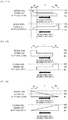
- FIG. 4A shows nails of respective curved surface correction levels.
- FIG. 4B shows a correspondence between the curved surface correction levels and correction areas.
- FIG. 5 is an explanatory diagram of the amount of drawing pixels in each scan according to the embodiment.
- FIG. 6 schematically shows change in density when a threshold range to a mask pattern is changed.
- FIG. 7 shows four areas into which an ink ejector is divided.
- FIG. 8 schematically shows threshold ranges in four scans.
- FIG. 9 is a flowchart showing the overall flow of a nail printing process according to the embodiment.
- FIG. 10 is a flowchart showing details of the nail printing process according to the embodiment.
- FIG. 11 is a flowchart showing details of the nail printing process according to the embodiment.
- FIG. 12A is an explanatory diagram showing how the amount of drawing pixels in each scan is set according to a modification.
- FIG. 12B is an explanatory diagram showing how the amount of drawing pixels in each scan is set according to another modification.
- FIG. 12C is an explanatory diagram showing how the amount of drawing pixels in each scan is set according to another modification.
- a nail printer (drawing apparatus) and a drawing method used by the nail printer (drawing apparatus) according to an embodiment of the present invention are described.
- various technically preferred limitations for carrying out the present invention are imposed on the embodiment below, the scope of the present invention is not limited to the embodiment or drawings.
- the drawing target surface of the present invention is not limited to the surface of a nail of a finger (thumb included).
- the drawing target may be a nail of a toe
- the drawing target surface may be the surface of the nail.
- FIG. 1A is a front view of the nail printer 1 and shows the internal configuration thereof.
- FIG. 1B is a side view showing the internal configuration of the nail printer 1 shown in FIG. 1A .
- the nail printer 1 of this embodiment includes a drawing mechanism 40 including a drawing head 41 as a drawing tool.
- the nail printer 1 is an inkjet printer which performs drawing on a nail T of a target finger U 1 .
- the nail printer 1 includes a case 2 and a body 10 housed in the case 2 .
- a cover 23 openable for replacement of the drawing head 41 of the drawing mechanism 40 described below is disposed on the upper part of a side face of the case 2 .
- the cover 23 freely rotates around a hinge or the like to be in a closed state and an open state as shown in FIG. 1 .
- An operation unit 25 (shown in FIG. 2 ) is disposed on the upper face (top panel) of the case 2 .
- the operation unit 25 is an input unit which is operated by a user to make various inputs.
- the operation unit 25 includes operation buttons (not shown) for making various inputs. Examples thereof include a power switch/button for turning on power of the nail printer 1 , a stop switch/button for stopping operation of the nail printer 1 , a design selection button for selecting/determining a design image to be drawn on the nail T, and a drawing start button (drawing switch) for making an instruction to start drawing.
- a display device 26 is disposed on the central part of the upper face (top panel) of the case 2 .
- the display device 26 is, for example, a liquid crystal display (LCD), an organic electroluminescent display or another flat display.
- the display device 26 appropriately displays, for example, a nail image(s) (an image of the target finger U 1 including an image of the nail T) obtained by photographing the target finger U 1 , an image(s) of the outline or the like of the nail T included in the nail image, a design menu screen for selecting a design image to be drawn on the nail T, a thumbnail image(s) for design check, and an instruction menu screen for displaying various instructions.
- a touchscreen for making various inputs may be integrally formed on the surface of the display device 26 .
- the body 10 is formed to be almost box-shaped.
- the body 10 includes a lower casing 11 disposed on the lower side in the case 2 and an upper casing 12 disposed above the lower casing 11 on the upper side in the case 2 .
- the lower casing 11 includes a back panel 111 , a bottom panel 112 , a pair of right and left side panels 113 a , 113 b , an X direction movement stage housing part 114 , a Y direction movement stage housing part 115 , and a partition 116 .
- the lower ends of the side panels 113 a , 113 b are connected to the left and right ends of the bottom panel 112 , respectively, such that the side panels 113 a , 113 b stand on the bottom panel 112 .
- the lower part of the back panel 111 is formed to sink in two steps to the front (toward the side from which fingers are to be inserted).
- the lower end of the back panel 111 is connected to the front end of the bottom panel 112 .
- the back panel 111 partitions the area defined by the bottom panel 112 and the side panels 113 a , 113 b into front and rear compartments.
- the space formed behind the sunken back panel 111 serves as the X direction movement stage housing part 114 and the Y direction movement stage housing part 115 (shown in FIG. 1B ).
- the X direction movement stage housing part 114 houses an X direction movement stage 45 of the drawing mechanism 40 when the drawing mechanism 40 has moved forward (toward the side from which fingers are to be inserted).
- the Y direction movement stage housing part 115 houses a Y direction movement stage 47 of the drawing mechanism 40 .
- the partition 116 is disposed in the lower casing 11 to partition the space on the front side in the lower casing 11 (space defined by the back panel 111 , the bottom panel 112 , and the side panels 113 a , 113 b on the side from which fingers are to be inserted) into upper and lower compartments.
- the partition 116 is almost horizontally disposed.
- the left and right ends of the partition 116 are connected to the side panels 113 a , 113 b , respectively.
- the rear end of the partition 116 is connected to the back panel 111 .
- the lower casing 11 is integrated with a finger holder 30 (shown in FIG. 1B ).
- the finger holder 30 includes a finger receiver 31 which receives a finger corresponding to the nail T on which an image is to be drawn (which is hereinafter referred to as “target finger U 1 ”) and a finger waiting room 32 where the fingers except the target finger U 1 (which are hereinafter referred to as “non-target fingers U 2 ”) are placed.
- the finger receiver 31 is disposed on the upper side of the partition 116 at the central part in the width (horizontal) direction of the lower casing 11 .
- the lower compartment of the lower casing 11 partitioned by the partition 116 constitutes the finger waiting room 32 .
- the ring finger as the target finger U 1 is inserted into the finger receiver 31 , and the other four digits (thumb, index finger, middle finger and little finger) as the non-target fingers U 2 are inserted into the finger waiting room 32 .
- the finger receiver 31 has an opening in the front face (the side from which fingers are to be inserted) of the lower casing 11 , and the lower face of the finger receiver 31 is defined by a finger placing part 116 a , which constitutes a part of the partition 116 .
- the finger placing part 116 a is to place, on an XY plane, a finger (target finger U 1 ) having the nail T on which an image is to be drawn.
- the finger receiver 31 has a window (not shown) on the upper face to expose the nail T of the target finger U 1 inserted into the finger receiver 31 .
- front walls 31 f (shown in FIG. 1A ) to wall up the front face side of the lower casing 11 are vertically disposed.
- a pair of guiding walls 31 g (shown in FIG. 1A ) to guide the target finger U 1 into the finger receiver 31 is vertically disposed on the upper face of the partition 116 from the center-side ends of the front walls 31 g to the depth of the finger receiver 31 such that the space defined by the guiding walls 31 g tapers off toward the depth of the finger receiver 31 .
- the user can pinch the partition 116 with the target finger U 1 inserted into the finger receiver 31 and the non-target fingers U 2 inserted into the finger waiting room 32 . This stabilizes the target finger U 1 inserted into the finger receiver 31 .
- a home area 60 for the drawing head 41 described below to stand by during non-drawing (standby mode) is provided in a movable area of the drawing head 41 on the upper face of the lower casing 11 and adjacent to the finger receiver 31 (on the right in FIG. 1A ).
- An inkjet maintenance unit is disposed in the home area 60 so as to face the drawing head 41 in the standby mode.
- the inkjet maintenance unit includes a cleaning mechanism (not shown) for cleaning an inkjet ejector 411 (nozzle surface) of the drawing head 41 described below and a capping mechanism (not shown) for maintaining a moist state of the ink ejector 411 (nozzle surface).
- Arrangement of the inkjet maintenance unit in the home area 60 is not limited to the one described above.
- the drawing mechanism 40 includes the drawing head 41 , a unit support member 44 which supports the drawing head 41 , the X direction movement stage 45 which moves the drawing head 41 in an X direction (X direction in FIG. 1A , i.e. right-left direction of the drawing apparatus 1 ), an X direction movement motor 46 , the Y direction movement stage 47 which moves the drawing head 41 in a Y direction (Y direction in FIG. 1B , i.e. front-back direction of the drawing apparatus 1 ), and a Y direction movement motor 48 .
- the drawing mechanism 40 with the drawing head 41 , performs drawing on the surface of the nail T while scanning the surface of the nail T an even number of times between one end and the other end along the width direction, wherein the surface of the nail T is the drawing target surface curved so as to have an acclivity and a declivity from one end to the other end along the width direction. How the drawing mechanism 40 (the drawing head 41 of the drawing mechanism 40 ) performs drawing is detailed below.
- the drawing head 41 is held by a head holder 43 and disposed on the unit support member 44 .
- the drawing head 41 is an ink-cartridge-integrated head configured such that ink cartridges (not shown), for example, for yellow (y), magenta (M) and cyan (C) inks are integrated with the ink ejector 411 (shown in FIG. 7 ) disposed on the faces of the ink cartridges, the faces facing the drawing target (nail T) (the lower face of the drawing head 41 in FIG. 1A , etc. in this embodiment).
- the ink ejector 411 includes a nozzle array constituted of nozzles to jet the color inks.
- the drawing head 41 makes the inks fine droplets and jets the fine droplets from the ink ejector 411 directly onto the surface of the drawing target (the surface of the nail T) in units of pixels, thereby performing drawing.
- the nozzles for jetting the inks each include a piezoelectric element (not shown) and can be individually controlled for ink jetting by a drawing control section 814 (shown in FIG. 2 ) described below.
- the ink ejector 411 is divided into four areas (Ar 1 to Ar 4 ), and the nozzles in the areas are successively driven (shown in FIG. 7 ), so that drawing is performed on a plurality of pixels P.
- the drawing head 41 may eject ink of any color other than the three colors mentioned above, and accordingly may include other ink cartridges storing ink of other colors and an ink ejector(s). Further, the nozzles of the drawing head 41 are not limited to those for ejecting ink with piezoelectric elements, and may have any configuration as far as they can be individually controlled for ink jetting. For example, the nozzles may be thermal nozzles provided with heaters.
- the unit support member 44 is fixed to an X direction movement part 451 attached to the X direction movement stage 45 .
- the X direction movement part 451 moves on the X direction movement stage 45 in the X direction along a guide (not shown) by being driven by the X direction movement motor 46 .
- This moves the drawing head 41 attached to the unit support member 44 in the X direction (X direction in FIG. 1A , i.e. right-left direction of the nail printer 1 ).
- the X direction movement stage 45 is fixed to a Y direction movement part 471 of the Y direction movement stage 47 .
- the Y direction movement part 471 moves on the Y direction movement stage 47 in the Y direction along a guide (not shown) by being driven by the Y direction movement motor 48 .
- the drawing head 41 attached to the unit support member 44 in the Y direction (Y direction in FIG. 1B , i.e. front-back direction of the nail printer 1 ).
- the X direction movement stage 45 is configured by being combined with the X direction movement motor 46 , a ball screw(s) (not shown) and the guide
- the Y direction movement stage 47 is configured by being combined with the Y direction movement motor 48 , a ball screw(s) (not shown) and the guide.
- the X direction movement motor 46 , the Y direction movement motor 48 and so forth constitute a head mover 49 as an XY drive unit which drives the drawing head 41 in the X direction and the Y direction.
- the drawing head 41 , the X direction movement motor 46 and the Y direction movement motor 48 of the drawing mechanism 40 are connected to and controlled by the drawing control section 814 (shown in FIG. 2 ) of a control device 80 described below.
- An imaging mechanism 50 includes an imager 51 and illuminators 52 .
- the illuminators 52 of the imaging mechanism 50 illuminate the nail T (the target finger U 1 including the nail T) inserted into the finger receiver 31 and exposed through the window.
- the imager 51 captures an image of the target finger U 1 to obtain a nail image which is an image of the target finger U 1 (an image of the finger including the nail image of the nail T).
- the imager 51 and the illuminators 52 are disposed on the upper casing 12 . More specifically, the imager 51 and the illuminators 52 of the imaging mechanism 50 are disposed on the lower face of a substrate 13 disposed on the upper casing 12 so as to face the partition 116 . Positions of the imager 51 and the illuminators 52 attached to the substrate 13 are not limited to those shown in the drawings.
- the imager 51 is, for example, a compact imager including a solid state imaging sensor having about two million or more imaging pixels (which are not drawing pixels described below) and a lens.
- the imager 51 of the imaging mechanism 50 captures an image of the target finger U 1 including the nail T to obtain a nail image.
- a nail information detection section 812 described below detects, in the nail image, the position and shape of the target finger U 1 , the position and shape (outline of the nail T) of the nail T as the drawing target, an aspect ratio of the nail T, and so forth.
- the illuminators 52 are, for example, white LEDs. In this embodiment, four illuminators 52 are disposed on the right, left, front and back of the imager 51 so as to surround the imager 51 . The illuminators 52 emit light downward to illuminate an imaging area beneath the imager 51 . The number arrangement and so forth of the illuminators 52 are not limited to those shown in the drawings.
- the imaging mechanism 50 is connected to and controlled by an imaging control section 811 (shown in FIG. 2 ), described below, of the control device 80 . Image data on the image (i.e. nail image) captured by the imaging mechanism 50 is stored in a nail image storage region 821 of a storage 82 described below.
- the control device 80 is, for example, disposed on the substrate 13 disposed on the upper casing 12 .
- FIG. 2 is a block diagram showing main components of a control system according to this embodiment.
- the control device 80 is a computer including a controller 81 and the storage 82 .
- the controller 81 includes a central processing unit (CPU) (not shown), and the storage 82 includes a read only memory (ROM) and a random access memory (RAM) (both not shown).
- CPU central processing unit
- RAM random access memory
- the storage 82 stores various programs and various data for operating the nail printer 1 . More specifically, the ROM of the storage 82 stores various programs including a nail information detection program for detecting the position and shape (outline) of the target finger U 1 , the position and shape (outline) of the nail T, the aspect ratio of the nail T and so forth, a drawing data generation program for generating data for drawing (drawing data) by performing curved surface correction and so forth on image data on a nail design, and a drawing program for a drawing process. The control device 80 executes these programs, thereby controlling the components of the nail printer 1 in whole.
- a nail information detection program for detecting the position and shape (outline) of the target finger U 1
- the position and shape (outline) of the nail T the aspect ratio of the nail T and so forth
- a drawing data generation program for generating data for drawing (drawing data) by performing curved surface correction and so forth on image data on a nail design
- a drawing program for a drawing process The control device 80 executes these programs
- the storage 82 includes the nail image storage region 821 storing the nail image(s) of the nail T of the target finger U 1 of the user captured by the imaging mechanism 50 , a nail information storage region 822 storing nail information (the outlines of the target finger U 1 and the nail T, the aspect ratio of the nail T, etc.) detected by the nail information detection section 812 , a nail design storage region 823 storing image data on the nail design(s) to be drawn on the nail T as the drawing target, and a data-for-correction storage region 824 storing data necessary for the correction according to a curved surface correction level of the nail T described below.
- the controller 81 includes, in terms of functions, the imaging control section 811 , the nail information detection section 812 , a drawing data generation section 813 , the drawing control section 814 and a display control section 815 .
- the CPU of the controller 81 operates to function as the imaging control section 811 , the nail information detection section 812 , the drawing data generation section 813 , the drawing control section 814 , the display control section 815 and so forth in cooperation with the programs stored in the ROM of the storage 82 .
- the imaging control section 811 controls the imager 51 and the illuminators 52 of the imaging mechanism 50 to cause the imager 51 to capture an image of the target finger U 1 (an image of the target finger U 1 including an image of the nail T, i.e. “nail image”) inserted into the finger receiver 31 .
- Image data on the nail image obtained by the imaging mechanism 50 is stored in the nail image storage region 821 of the storage 82 .
- the nail information the outlines of the target finger U 1 and the nail T, the aspect ratio of the nail T and so forth are detected in the nail image obtained by the imaging mechanism 50 .
- the nail information detected in the nail image is, however, not limited thereto, and for example, curvature of the nail T may be detected on the basis of the nail image directly.
- the nail information detection section 812 detects, in the nail image, which is an image of the target finger U 1 including the nail T obtained by the imager 51 of the imaging mechanism 50 , the outline of the finger defining the region of the target finger U 1 , the outline (shape) of the nail T defining the region of the nail T as the drawing target, and a curved surface level indicating curvature (degree of curve) of the surface of the nail T as the drawing target in the nail width direction, and so forth.
- the nail information detection section 812 detects the shapes (outlines) of the target finger U 1 and the nail T as the nail information on the basis of, for example, color difference between each of the target finger U 1 and the nail T and the background (the finger placing part 116 a in this embodiment), or obtains the shape (outline) of the nail T by detecting the boundary between the nail T and the skin of the target finger U 1 on the basis of (i) color difference between the nail T and the target finger U 1 , (ii) how shadows appear, and so forth.
- the nail information detection section 812 determines the curvature of the surface of the nail T in the width direction on the basis of the darkness of the shadows appearing in the nail images, and obtains the curved surface correction level indicating what level of the correction is needed.
- the curved surface correction level includes information corresponding to the curvature of the surface of the nail T at each of points at predetermined intervals in the horizontal direction, namely, the tilt of the surface of the nail T from the horizontal.
- the method for detecting the nail information with the nail information detection section 812 is not limited to those described herein and may be any method.
- the curved surface correction level is detected by the nail information detection section 812 in the above, the curved surface level may not be detected by the nail information detection section 812 , and a standard value as the curved surface correction level may be preset and changed by the user, for example.
- FIG. 3 is a schematic view showing the nail T as the drawing target.
- FIG. 3 includes a plan view of the surface of the nail T as the drawing target surface viewed from the above and a front view of the nail T viewed from the tip side, where “W” represents an apparent width when the nail surface is viewed from the above as a plane.
- “C” represents a non-correction region which is a relatively flat central region of the nail T in the nail width direction and requires no curved surface correction
- “LE” and “RE” represent a left correction region and a right correction region, respectively, which are left and right curved regions of the nail T in the nail width direction and requires the curved surface correction.
- FIG. 3 includes a plan view of the surface of the nail T as the drawing target surface viewed from the above and a front view of the nail T viewed from the tip side, where “W” represents an apparent width when the nail surface is viewed from the above as a plane.
- “C” represents a non-correction region which is a
- the surface of the nail T as the drawing target surface is curved such that one end E 1 and the other end E 2 in the width direction are relatively low, and the central part in the width direction is relatively high. If the drawing head 41 ejects ink droplets to such a drawing target surface while moving (scanning the drawing target surface) in the direction from the one end E 1 to the other end E 2 along the width direction of the nail T, the travelling direction (ejection direction) of the ejected ink droplets is, as indicated by d in FIG. 3 , a direction inclined to the moving direction of the drawing head 41 from the vertical direction.
- the ink droplets land well at a low part(s)/region(s) in height of the surface of the nail T too if ejected from the drawing head 41 which is scanning, of the surface of the nail T, a region acclivitous in the moving direction of the drawing head 41 .
- the drawing head 41 is scanning, of the surface of the nail T, a region declivitous in the moving direction of the drawing head 41 , angle between the travelling direction d of the ink droplets ejected from the drawing head 41 (shown with long dashed double-short dashed lines at the upper side in FIG. 3 ) and the inclined direction of the surface of the nail T is small.
- the central part of the nail T in the width direction is regarded as the non-correction region C, which does not require the correction
- a predetermined width region on the left of the non-correction region C is regarded as the left correction region LE
- a predetermined width region on the right of the non-correction region C is regarded as the right correction region RE
- the correction is performed in the left correction region LE and the right correction region RE.
- the nail information detection section 812 categorizes the nail T on the basis of the curvature of the nail T as one of six curved surface correction levels of 0 to 5 shown in FIG. 4A .
- the method for categorizing the nail T as one of the curved surface correction levels with the nail information detection section 812 is not particularly limited.
- threshold values or the like for the respective curved surface correction levels are stored, and referring to the threshold values, the nail information detection section 812 determines as which of the curved surface correction levels, the nail T of the user is categorized, when detecting the shape of the surface of the nail T.
- the number of the curved surface correction levels is not limited to six as shown in FIG.
- the “curved surface correction level 0” represents a curved surface level of a substantially flat surface of the nail T
- the “curved surface correction level 1” represents a curved surface level of an overall flat surface of the nail T having a relatively small curvature
- the “curved surface correction level 5” represents a curved surface level of a curved surface of the nail T having a relatively large curvature
- the “curved surface correction level 2”, the “curved surface correction level 3” and the “curved surface correction level 4” represent curved surface levels of a typical/standard surface of the nail T having a curvature between that of the “curved surface correction level 1” and that of the “curved surface correction level 5” and increase curvature in this order, and they are provided with the threshold values.
- a table in which correction areas are correlated with the respective curved surface correction levels 0 to 5 is stored.
- the correction areas each specify the width of each correction region, where the correction is performed, in percentage (%) in the nail width W. For example, if the nail T is categorized as the curved surface correction level 1, a 5% width region from the left end of the nail T is the left correction region LE, a 5% width region from the right end of the nail T is the right correction region RE, and the remaining central part is the non-correction region C.
- the nail T is categorized as the curved surface correction level 5
- a 25% width region from the left end of the nail T is the left correction region LE
- a 25% width region from the right end of the nail T is the right correction region RE
- the remaining central part is the non-correction region C.
- the drawing data generation section 813 generates data necessary to draw the nail design on the nail T of the target finger U 1 with the drawing head 41 .
- the drawing data generation section 813 generates the drawing data for fitting the nail design chosen by the user to the shape of the nail of the user and controlling, on the basis of the curved surface correction level detected by the nail information detection section 812 , which pixel(s) are to be drawn (i.e. which nozzle(s) of the ink ejector 411 of the drawing head 41 for pixel(s) are to be driven) in which scan among scans.
- the drawing control section 814 controls the drawing head 41 to scan the surface of the nail as the drawing target surface multiple times while driving all or some of the nozzles on the basis of the drawing data generated by the drawing data generation section 813 , thereby drawing pixels and accordingly forming an image constituted of the drawn pixels combined.
- the drawing control section 814 causes the drawing head 41 to reciprocate on the nail T and form an image during four scans (four passes).
- the drawing control section 814 outputs control signals to the drawing mechanism 40 on the basis of the drawing data generated by the drawing data generation section 813 so as to control the X direction movement motor 46 , the Y direction movement motor 48 , the drawing head 41 and so forth of the drawing mechanism 40 to perform drawing on the nail T on the basis of the drawing data.
- the drawing data generation section 813 and the drawing control section 814 constitute a control unit which controls drawing operation of the drawing mechanism 40 .
- the drawing mechanism 40 performs drawing on the drawing target surface while scanning the surface of the nail T as the drawing target surface an even number of times from one end to the other end and from the other end to the one end along the width direction of the nail T.
- the drawing data generation section 813 and the drawing control section 814 which constitute the control unit that controls the drawing operation of the drawing mechanism 40 , change the amount of drawing pixels to be drawn on the region of the drawing target surface (the surface of the nail T) acclivitous in the moving direction of the drawing head 41 during a scan(s) of the acclivitous region so as to reduce the amount from a large amount to a small amount from the starting point of the scan of the acclivitous region in the moving direction of the drawing head 41 .
- the drawing data generation section 813 and the drawing control section 814 change the amount of the drawing pixels to be drawn on the region of the drawing target surface (the surface of the nail T) declivitous in the moving direction of the drawing head 41 during the scan of the declivitous region so as to reduce the amount from, at the largest, the amount at the ending point of the scan of the acclivitous region from the starting point of the scan of the declivitous region in the moving direction of the drawing head 41 .
- the drawing pixels are pixels to be drawn by the drawing head 41 during scans.
- the drawing data generation section 813 and the drawing control section 814 control the drawing operation of the drawing mechanism 40 such that change in the amount of the drawing pixels during one scan and change in the amount of the drawing pixels during another scan which is paired with the one scan among the even number of scans complement one another, namely, such that change in the amount of the drawing pixels during a first scan from one end to the other end on an outward way and change in the amount of the drawing pixels during a second scan from the other end to the one end on a homeward way complement one another.
- FIG. 5 is an explanatory diagram of percentage of the amount of the drawing pixels to be drawn by the drawing mechanism 40 (which is hereinafter referred to as “drawing pixel percentage”) during each scan according to this embodiment.
- the moving direction of the drawing head 41 in the 1 st and 3 rd scans, is the right direction R, and in the 2 nd and 4 th scans, the moving direction of the drawing head 41 is the left direction L.
- a direction orthogonal to the moving direction is referred to as a line direction.
- Pixels to be drawn on the nail T by the drawing head 41 are arranged in the moving direction and the line direction to be a matrix.
- W represents the width of the nail T
- the curved surface correction level is 4 and the correction area is 20% accordingly
- a W ⁇ 20/100 region from the left end of the nail T in the width direction is the left correction region LE (first region or second region)
- a W ⁇ 20/100 region from the right end of the nail T in the width direction is the right correction region RE (second region or first region)
- the remaining central part corresponding to 60% of the width W of the nail T is the non-correction region C, where the correction is not performed.
- Pixel lines of the left correction region LE are referred to as the 1 st line, the 2 nd line, the 3 rd line, . . . and the a th line from the left end
- pixel lines of the right correction region RE are referred to as the b th line, . . . , the c th line, . . . and the d th line from the right end.
- the number of the pixels P in each line depends on the shape and the size of the nail T, and hence may be different from line to line.
- Drawing during this scan is referred to as “R 2 L 2 ” in FIG. 5 and so forth.
- the drawing head 41 moves from the left to the right (from the left to the right in FIG. 5 ), thereby performing a scan (3 rd scan), and the moving direction (drawing direction) of the drawing head 41 is the right direction R (first direction or second direction).
- Drawing during this scan is referred to as “L 2 R 3 ” in FIG. 5 and so forth.
- the drawing head 41 moves from the right to the left (from the right to the left in FIG.
- the ratio of the drawing amount of the drawing pixels to be drawn (first scan drawing pixel(s) or third scan drawing pixel(s)) in the 1 st line during the 1 st scan to the drawing amount (at least one of the area of drawing (drawing area), the number of the drawing pixels and the number of dots as ink marks deposited in the nail T by drawing) required for all the pixels P to be drawn in the 1 st line (i.e.
- drawing pixel percentage of a design image is 50%; at the ending point in the left correction region LE (a border side of the left correction region LE with the non-correction region C), namely, in the a th line of the left correction region LE, the ratio of the drawing amount of the drawing pixels to be drawn (first scan drawing pixel(s) or third scan drawing pixel(s)) in the a th line during the 1 st scan to the drawing amount required for all the pixels P to be drawn in the a th line of the design image is 25%; and from the 1 st line to the a th line of the left correction region LE, the ratio of the drawing amount of the drawing pixels to be drawn in each line during the 1 st scan to the drawing amount required for all the pixels P to be drawn in each line is changed to be reduced from 50% to 25%.
- the ratio of the drawing amount of the drawing pixels to be drawn in each line during the 1 st scan to the drawing amount required for all the pixels P to be drawn in each line is 25%.
- the ratio of the drawing amount of the drawing pixels to be drawn is 25%;
- the ratio of the drawing amount of the drawing pixels to be drawn is 0%; and from the b th line to the d th line of the right correction region RE, the ratio of the drawing amount of the drawing pixels to
- “drawing pixel percentage”) of the design image is 50%; at the ending point in the right correction region RE (a border side of the right correction region RE with the non-correction region C), namely, in the b th line of the right correction region RE, the ratio of the drawing amount of the drawing pixels to be drawn (fourth scan drawing pixel(s) or second scan drawing pixel(s)) in the d th line during the 2 nd scan to the drawing amount required for all the pixels P to be drawn in the b th line of the design image is 25%; and from the d th line to the b th line of the right correction region RE, the ratio of the drawing amount of the drawing pixels to be drawn in each line during the 2 nd scan to the drawing amount required for all the pixels P to be drawn in each line is changed to be reduced from 50% to 25%.
- the ratio of the drawing amount of the drawing pixels to be drawn in each line during the 2 nd scan to the drawing amount required for all the pixels P to be drawn in each line is 25%.
- the ratio of the drawing amount of the drawing pixels to be drawn (second scan drawing pixel(s) or fourth scan drawing pixel(s)) in the a th line during the 2 nd scan to the drawing amount required for all the pixels P to be drawn in the a th line of the design image is 25%;
- the ratio of the drawing amount of the drawing pixels to be drawn (second scan drawing pixel(s) or fourth scan drawing pixel(s)) in the 1 st line during the 2 nd scan to the drawing amount required for all the pixels P to be drawn in the 1 st line of the design image is 0%; and from the a th line to the 1 st line of the left correction region LE, the ratio of the drawing amount of the drawing pixels to be drawn
- pixels not drawn (no-drawing pixels) during the first scan from one end to the other end of the nail T in the width direction on the outward way are drawn during the second scan from the other end to the one end of the nail T in the width direction on the homeward way (R 2 L 2 in FIG. 5 ), so that change in the drawing pixel percentage during the first scan on the outward way (L 2 R 1 in FIG. 5 ) and change in the drawing pixel percentage during the second scan on the homeward way (R 2 L 2 in FIG. 5 ) have a mutually complementary relationship.
- drawing can be performed in both outward and homeward directions in which scans are performed along the width direction of the nail T, and there is a point(s) where drawing is performed during a scan(s) in one of the directions only.
- the drawing data generation section 813 and the drawing control section 814 which constitute the control unit that controls the drawing operation of the drawing mechanism 40 , adjust/determine the correction area, where the amount of the drawing pixels is corrected so as not to remain the same, according to the curvature (i.e. the curved surface correction level) of the surface of the nail T as the drawing target surface, and control degree of change in the amount of the drawing pixels to be drawn by the drawing mechanism 40 .
- the drawing data generation section 813 and the drawing control section 814 control the amount of the drawing pixels to be drawn by the drawing mechanism 40 to change linearly. This can prevent streaks or the like from appearing between the region where the amount of the drawing pixels is adjusted (i.e. the left correction region LE or the right correction region RE) and the region where the amount of the drawing pixels is not adjusted (i.e. the non-correction region C), and can realize beautifully finished nail prints.
- the drawing data generation section 813 which constitutes a part of the control unit that controls the drawing operation of the drawing mechanism 40 , controls the percentage of the drawing amount of the drawing pixels (i.e. the drawing pixel percentage) to be drawn by the drawing mechanism 40 with the dots of the mask pattern.
- FIG. 6 shows examples of the mask pattern (singling mask).
- the mask pattern (singling mask) has a square area of 256 dots in the vertical direction ⁇ 256 dots in the horizontal direction, and 65,536 dots are randomly and evenly (dispersedly) arranged in the area.
- the dots are arranged at the density the same as the resolution in drawing of the drawing mechanism 40 .
- To each dot one of numerical values of 0 to 255 is assigned, and every 256 dots have the same numerical value and are randomly and evenly arranged in the area.
- a plurality of mask patterns is applied to cover the entire drawing target surface.
- a threshold range to the numerical values assigned to the dots is set so as to extract dots in the threshold range, and of all the pixels constituting a design image, pixels corresponding to the extracted dots are set as the drawing pixels to be drawn by the drawing mechanism 40 , and the other pixels are set as the non-drawing pixels not to be drawn by the drawing mechanism 40 . More specifically, as shown in FIG.
- the drawing pixel percentage is 5%; if the threshold range is set to 0 to 25, the drawing pixel percentage is 10%; if the threshold range is set to 0 to 38, the drawing pixel percentage is 15%; if the threshold range is set to 0 to 63, the drawing pixel percentage is 25%; and if the threshold range is set to 0 to 255, the drawing pixel percentage is equal to the drawing amount required for all the pixels P in its corresponding line, namely, 100%.
- the above values of the threshold range are examples, and even if the threshold range is set to 64 to 127, 128 to 191, or 192 to 255, the drawing pixel percentage is 25%.
- positions of the corresponding dots in the mask pattern also differ.
- this mask pattern (singling mask)
- all the dots are randomly and evenly arranged, and hence regardless of whether the drawing pixel percentage is high or low as a result of the threshold range applied thereto to set the drawing pixels in each scan, the density is uniform as shown in FIG. 6 .
- a table of the threshold range set for such a mask pattern is prepared, and on the basis of the table, in the 1 st pass (1 st scan), the threshold range is set to 0 to 63, and drawing is performed with the drawing pixel percentage of 25%; in the 2 nd pass (2 nd scan), the threshold range is set to 64 to 127, and drawing is performed with the drawing pixel percentage of 25%; in the 3 rd pass (3 rd scan), the threshold range is set to 128 to 191, and drawing is performed with the drawing pixel percentage of 25%; and in the 4 th pass (4 th scan), the threshold range is set to 192 to 255, and drawing is performed with the drawing pixel percentage of 25%.
- the threshold range to the mask pattern is set to 0 to 127 and gradually changed to 0 to 63; in the non-correction region C, the threshold range is set to (kept at) 0 to 63; and in the right correction region RE, the threshold range is set to 0 to 63 and gradually changed to 0, and at each point of each region, the drawing pixel percentage corresponding to the threshold range is set, and the drawing mechanism 40 performs drawing with the drawing pixel percentage.
- the threshold range is set to 0 to 127 and gradually changed to 64 to 127; in the non-correction region C, the threshold range is set to (kept at) 64 to 127; and in the left correction region LE, the threshold range is set to 64 to 127 and gradually changed to 127, and at each point of each region, the drawing pixel percentage corresponding to the threshold range is set, and the drawing mechanism 40 performs drawing with the drawing pixel percentage. That is, the drawing pixels in the 1 st pass are different from the drawing pixels in the 2 nd pass.
- the threshold range is set to 128 to 255 and gradually changed to 128 to 191; in the non-correction region C, the threshold range is set to (kept at) 128 to 191; and in the right correction region RE, the threshold range is set to 128 to 191 and gradually changed to 128, and at each point of each region, the drawing pixel percentage corresponding to the threshold range is set, and the drawing mechanism 40 performs drawing with the drawing pixel percentage.
- the threshold range is set to 128 to 255 and gradually changed to 192 to 255; in the non-correction region C, the threshold range is set to (kept at) 192 to 255; and in the left correction region LE, the threshold range is set to 192 to 255 and gradually changed to 255, and at each point of each region, the drawing pixel percentage corresponding to the threshold range is set, and the drawing mechanism 40 performs drawing with the drawing pixel percentage. That is, the drawing pixels in the 3 rd pass and the 4 th pass are different from the drawing pixels in the 1 st pass and the 2 nd pass, and the drawing pixels in the 3 rd pass are different from the drawing pixels in the 4 th pass.
- the display control section 815 controls and thereby causes the display device 26 to display various display screens.
- the display control section 815 causes the display device 26 to display, for example, the design menu screen of nail designs, thumbnail images for design check, nail images obtained by photographing the target finger U 1 , and various instruction screens and operation screens.
- the display control section 815 may cause the display device 26 to display the determined curved surface level to request the user to confirm.
- the curved surface level may be changed or finely adjusted by the user through the operation unit 25 , the touchscreen or the like if the user judges that the curved surface level, which has been automatically selected by the apparatus, is not proper for his/her nail T.
- FIG. 9 is a flowchart showing the overall flow of a nail printing process performed by the nail printer 1 .
- the user first turns on the power switch to start the control device 80 .
- the imaging control section 811 controls the imaging mechanism 50 to cause the imager 51 to capture an image of the target finger U 1 while causing the illuminators 52 to illuminate the target finger U 1 .
- the imaging control section 811 obtains an image (nail image) of the nail T of the target finger U 1 (Step S 1 ).
- the nail information detection section 812 detects, in the nail image, the nail information on the outline of the nail T, the position of the nail T in the height direction and so forth (Step S 2 ). The nail information detection section 812 then obtains, from the nail information, the curved surface correction level indicating the curvature of the nail T in the width direction as the drawing target (Step S 3 ).
- the drawing data generation section 813 determines the correction area set for the curved surface correction level (Step S 4 ). The drawing generation section 813 then generates the drawing data (image data for drawing) on the basis of, for example, the determined correction area set for the curved surface correction level, taking the nail information on the shape and so forth of the nail T into account (Step S 5 ).
- the drawing control section 814 controls the operation of the drawing head 41 on the basis of the generated drawing data, and starts the drawing process of the nail design on the nail T (Step S 6 ).
- the drawing control section 814 determines whether or not drawing is L 2 R 1 in the 1 st pass (1 st scan) (Step S 11 ).
- the drawing control section 814 controls the drawing mechanism 40 to perform the drawing process corresponding to L 2 R 1 (Step S 12 ). More specifically, the drawing process is performed by drawing together with correction, wherein the correction is that, in the left correction region LE, from the starting point (i.e. the left end) to the ending point, the drawing pixel percentage is gradually reduced from 50% to 25%; in the non-correction region C, the drawing pixel percentage is 25%; and in the right correction region RE, the drawing pixel percentage is gradually reduced from 25% to 0%.
- the drawing process corresponding to L 2 R 1 in the 1 st pass (1 st scan) is described with reference to FIG. 11 .
- the drawing control section 814 determines whether or not the drawing position is the left correction region LE (Step S 21 ).
- the drawing control section 814 performs control to perform drawing with the drawing pixel percentage for the left correction region LE (Step S 22 ). More specifically, in the left correction region LE, from the starting point (i.e. the left end) to the ending point, drawing is performed while the drawing pixel percentage is gradually reduced from 50% to 25%.
- the drawing control section 814 determines whether or not the drawing position is the non-correction region C (Step S 23 ).
- the drawing control section 814 performs control to perform drawing with the drawing pixel percentage for the non-correction region C (Step S 24 ). More specifically, in the non-correction region C, drawing is performed with the drawing pixel percentage of 25%.
- the drawing control section 814 determines whether or not the drawing position is the right correction region RE (Step S 25 ).
- the drawing control section 814 performs control to perform drawing with the drawing pixel percentage for the right correction region RE (Step S 26 ). More specifically, in the right correction region RE, drawing is performed while the drawing pixel percentage is gradually reduced from 25% to 0%. Steps similar to these are taken when drawings of R 2 L 2 , L 2 R 3 and R 2 L 4 are performed.
- the drawing control section 814 determines whether or not the drawing is R 2 L 2 in the 2 nd pass (2 nd scan) (Step S 13 ).
- the drawing control section 814 controls the drawing mechanism 40 to perform the drawing process corresponding to R 2 L 2 (Step S 14 ). More specifically, the drawing process is performed by drawing together with correction, wherein the correction is that, in the right correction region RE, from the starting point (i.e. the right end) to the ending point, the drawing pixel percentage is gradually reduced from 50% to 25%; in the non-correction region C, the drawing pixel percentage is 25%; and in the left correction region LE, the drawing pixel percentage is gradually reduced from 25% to 0%.
- the drawing control section 814 determines whether or not the drawing is L 2 R 3 in the 3 rd pass (3 rd scan) (Step S 15 ).
- the drawing control section 814 controls the drawing mechanism 40 to perform the drawing process corresponding to L 2 R 3 (Step S 16 ). More specifically, as with L 2 R 1 in the 1 st pass (1 st scan), the drawing process is performed by drawing together with correction, wherein the correction is that, in the left correction region LE, from the starting point (i.e. the left end) to the ending point, the drawing pixel percentage is gradually reduced from 50% to 25%; in the non-correction region C, the drawing pixel percentage is 25%; and in the right correction region RE, the drawing pixel percentage is gradually reduced from 25% to 0%.
- the drawing control section 814 determines that the drawing is R 2 L 4 in the 4 th pass (4 th scan), and controls the drawing mechanism 40 to perform the drawing process corresponding to R 2 L 4 (Step S 17 ). More specifically, as with R 2 L 2 in the 2 nd pass (2 nd scan), the drawing process is performed by drawing together with correction, wherein the correction is that, in the right correction region RE, from the starting point (i.e.
- the drawing pixel percentage is gradually reduced from 50% to 25%; in the non-correction region C, the drawing pixel percentage is 25%; and in the left correction region LE, the drawing pixel percentage is gradually reduced from 25% to 0%.
- the drawing control section 814 finishes the drawing process(es) shown in Step S 6 in FIG. 9 .
- the drawing control section 814 determines whether or not all of the drawing processes on the nail T have finished (Step S 7 ). When determining that all of the drawing processes on the nail T have finished (Step S 7 : YES), the drawing control section 814 finishes the nail printing process. On the other hand, when determining that not all of the drawing processes on the nail T have finished yet (i.e. the drawing head 41 has not finished four scans yet) (Step S 7 : NO), the drawing control section 814 returns to Step S 6 to repeat the drawing process.
- the nail printer 1 includes the drawing head 41 which performs drawing on the surface of the nail T as the drawing target surface while moving in a first direction and a second direction different from one another. If the drawing target surface (surface of the nail T) has a first region which is acclivitous in the first direction and declivitous in the second direction, the drawing head 41 draws at least a part of a plurality of first pixels constituting an image to be drawn on the first region while performing the first scan in which the drawing head 41 moves in the first direction and the second scan in which the drawing head 41 moves in the second direction.
- the control device 81 controls the ratio of the drawing amount of the drawing pixels to be drawn by the drawing head 41 during the first scan to the drawing amount required for the plurality of the first pixels, which constitutes the image to be drawn on the first region, to be higher than the ratio of the drawing amount of the drawing pixels to be drawn by the drawing head 41 during the second scan to the drawing amount required for the plurality of the first pixels. While an acclivity is being scanned, ink droplets land well, and hence even if the drawing amount (at least one of the drawing area, the number of the drawing pixels and the number of dots as ink marks deposited in the nail T by drawing) is increased, a high-definition image(s) can be drawn.
- ink droplets may not land although ink is ejected from the drawing head 41 , or even if ink droplets land, they tend to land at inaccurate positions. Reducing the drawing amount at a scene where ink droplets tend to land not well and increasing the drawing amount at a scene where ink droplets can land well can make a drawn image(s) excellently finished. Further, the drawing operation is controlled such that change in the amount of the drawing pixels during the scan in the direction to ascend a slope and change in the amount of the drawing pixels during the scan in the direction to descend the slope complement each other.
- pixels can be drawn during another scan which is paired with the one scan. This prevents variation in density from occurring in a drawn image(s) as a whole when viewed in the width direction of the nail T, and can realize a high-definition drawn image(s).
- an image having no density unevenness can be formed by one or more reciprocations of the drawing head 41 .
- the drawing target surface is the surface of a nail curved such that one end part and the other end part in the width direction are low in height, and the central part in the width direction is high in height, the drawing amount can be controlled. This can realize beautiful nail prints.
- the degree of change in the drawing amount to be drawn by the drawing mechanism 40 can be controlled according to the curvature of the drawing target surface (e.g. the surface of the nail T).
- the curve of the nail T is various from person to person. Controlling the drawing amount taking the curvature into account, thereby performing the correction appropriately for any shape of the nail T, can realize high-definition nail designs.
- the drawing amount to be drawn by the drawing mechanism 40 is changed linearly. This prevents streaks or the like from appearing at the points where the drawing amount is adjusted, and can realize beautifully finished nail prints.
- the mask pattern(s) having dots to which numerical values are assigned and which are randomly arranged is provided, and the drawing amount to be drawn by the drawing mechanism 40 is controlled by setting a threshold range to the numerical values assigned to the dots of the mask pattern. This can arrange the drawing pixels evenly, and can realize drawn images having no density unevenness.
- the drawing amount is linearly reduced from 50% to 25%
- the drawing amount is linearly reduced from 25% to 0%.
- how to set the drawing pixels in each region is not limited to the manner described in the above embodiment.
- the drawing pixel percentage is 50% in a predetermined area from the starting point (i.e. the left end), and in the right correction region RE, the drawing pixel percentage is 0% in its corresponding area.
- the drawing pixel percentage is 50%, and in its corresponding entire right correction region RE, the drawing pixel percentage is 0%, so that drawing is not performed in the declivitous part.
- a streak(s) may appear in a border part at the point.
- streaks in such border parts may not bother the user.
- a drawn image(s) looks beautifully finished.
- the amount of the drawing pixels may be changed linearly in whole from one end to the other end in the direction along the curved surface. In this case, no non-correction region C is provided.
- the amount of the drawing pixels is changed linearly in whole, too, as far as the drawing pixels are balanced between scans (drawings) which form a pair, namely, changes in the amounts of the drawing pixels during the scans complement one another, a beautifully finished image(s) as a whole can be realized.
- the amount of the drawing pixels is changed linearly, but not limited thereto, and may be changed curvedly.
- changes in the amounts of the drawing pixels during scans (drawings) which form a pair are set such that curves complementing one another are drawn, a beautifully finished image(s) having no density unevenness can be realized.
- drawing on the drawing target surface is performed by four passes (scans), but the number of the passes for drawing on the drawing target surface is not limited to four. As far as at least one pair of scans during which changes in the drawing amounts complement one another is present, any even number of scans, namely, two, six or a larger even number, can be adopted.
- the ink ejector 411 of the drawing head 41 is divided into four areas of Ar 1 to Ar 4 , but not limited to such a configuration and may be divided into a larger number of areas.
- the mask pattern(s) (singling mask(s)) shown in FIG. 6 are used to sort the drawing pixels to be drawn from the non-drawing pixels not to be drawn during each scan, but the method for sorting the drawing pixels to be drawn from the non-drawing pixels not to be drawn during each scan is not limited thereto, and any method for performing printing while thinning out pixels to be drawn (nozzles corresponding thereto) can be used.
- image data on nail designs is stored in the storage 82 of the drawing apparatus, but may be obtained from an external apparatus via the Internet, for example.
- the control unit which performs drawing control such as the correction may be provided as an external apparatus, and the drawing apparatus itself may only have the functional part(s) which performs the drawing process(es) in response to control signals from the external apparatus.
- the drawing head 41 employs an inkjet system, but, for example, both an inkjet drawing head and a drawing tool, such as a pen, may be provided and used for drawing.
Landscapes
- Engineering & Computer Science (AREA)
- Manufacturing & Machinery (AREA)
- Ink Jet (AREA)
Applications Claiming Priority (3)
| Application Number | Priority Date | Filing Date | Title |
|---|---|---|---|
| JP2017175298A JP7035394B2 (ja) | 2017-09-13 | 2017-09-13 | 描画装置及び描画方法 |
| JP2017-175298 | 2017-09-13 | ||
| PCT/JP2018/030026 WO2019054110A1 (en) | 2017-09-13 | 2018-08-10 | DRAWING APPARATUS AND DRAWING METHOD |
Publications (2)
| Publication Number | Publication Date |
|---|---|
| US20190313764A1 US20190313764A1 (en) | 2019-10-17 |
| US10893736B2 true US10893736B2 (en) | 2021-01-19 |
Family
ID=65723600
Family Applications (1)
| Application Number | Title | Priority Date | Filing Date |
|---|---|---|---|
| US16/462,387 Active US10893736B2 (en) | 2017-09-13 | 2018-08-10 | Drawing apparatus and drawing method |
Country Status (4)
| Country | Link |
|---|---|
| US (1) | US10893736B2 (ja) |
| JP (1) | JP7035394B2 (ja) |
| CN (1) | CN110121278B (ja) |
| WO (1) | WO2019054110A1 (ja) |
Families Citing this family (3)
| Publication number | Priority date | Publication date | Assignee | Title |
|---|---|---|---|---|
| JP6973437B2 (ja) | 2019-03-25 | 2021-11-24 | カシオ計算機株式会社 | 印刷装置、印刷方法及びプログラム |
| CA3159758A1 (en) | 2019-10-29 | 2021-05-06 | NailPro, Inc. | Automated total nail care systems, devices and methods |
| JP7161512B2 (ja) * | 2020-10-09 | 2022-10-26 | 菊水電子工業株式会社 | 爪の採寸方法、ネイルシール製造方法、情報処理装置、ネイルシール製造システム、及びプログラム |
Citations (3)
| Publication number | Priority date | Publication date | Assignee | Title |
|---|---|---|---|---|
| US6286517B1 (en) | 1998-12-22 | 2001-09-11 | Pearl Technology Holdings, Llc | Fingernail and toenail decoration using ink jets |
| JP2015047473A (ja) | 2013-09-05 | 2015-03-16 | カシオ計算機株式会社 | ネイルプリント装置及びネイルプリント装置の印刷方法 |
| WO2016128282A1 (en) | 2015-02-09 | 2016-08-18 | Oce-Technologies B.V. | Method for printing a plurality of voxels of an object |
Family Cites Families (7)
| Publication number | Priority date | Publication date | Assignee | Title |
|---|---|---|---|---|
| JP5494562B2 (ja) * | 2011-04-28 | 2014-05-14 | カシオ計算機株式会社 | 曲面印刷装置及び曲面印刷装置の印刷制御方法 |
| JP5853885B2 (ja) * | 2011-09-29 | 2016-02-09 | カシオ計算機株式会社 | ネイルプリント装置 |
| JP6127793B2 (ja) * | 2013-07-18 | 2017-05-17 | カシオ計算機株式会社 | ネイルプリント装置及びネイルプリント装置の印刷方法 |
| JP6561463B2 (ja) * | 2014-12-25 | 2019-08-21 | カシオ計算機株式会社 | 描画装置、描画装置の動作制御方法及び描画装置の動作制御プログラム |
| JP6428411B2 (ja) * | 2015-03-18 | 2018-11-28 | カシオ計算機株式会社 | 描画装置及び爪傾き検出方法 |
| JP2017006294A (ja) * | 2015-06-19 | 2017-01-12 | カシオ計算機株式会社 | リムーバペン、描画装置及び描画装置を用いたインク除去方法 |
| JP6547542B2 (ja) * | 2015-09-18 | 2019-07-24 | カシオ計算機株式会社 | 爪形状取得装置及び描画装置、並びに爪形状取得装置の制御プログラム |
-
2017
- 2017-09-13 JP JP2017175298A patent/JP7035394B2/ja active Active
-
2018
- 2018-08-10 CN CN201880005565.5A patent/CN110121278B/zh active Active
- 2018-08-10 US US16/462,387 patent/US10893736B2/en active Active
- 2018-08-10 WO PCT/JP2018/030026 patent/WO2019054110A1/en active Application Filing
Patent Citations (5)
| Publication number | Priority date | Publication date | Assignee | Title |
|---|---|---|---|---|
| US6286517B1 (en) | 1998-12-22 | 2001-09-11 | Pearl Technology Holdings, Llc | Fingernail and toenail decoration using ink jets |
| JP2003534083A (ja) | 2000-05-26 | 2003-11-18 | パール テクノロジー ホールディングス リミテッド ライアビリティ カンパニー | インクジェットを使用した手指爪および足指爪の装飾 |
| JP2015047473A (ja) | 2013-09-05 | 2015-03-16 | カシオ計算機株式会社 | ネイルプリント装置及びネイルプリント装置の印刷方法 |
| WO2016128282A1 (en) | 2015-02-09 | 2016-08-18 | Oce-Technologies B.V. | Method for printing a plurality of voxels of an object |
| US20170329309A1 (en) | 2015-02-09 | 2017-11-16 | Océ-Technologies B.V. | Method for printing a plurality of voxels of an object |
Non-Patent Citations (2)
| Title |
|---|
| International Preliminary Report on Patentability (IPRP) dated Mar. 17, 2020 issued in International Application No. PCT/JP2018/030026. |
| International Search Report (ISR) and Written Opinion dated Sep. 25, 2018 issued in International Application No. PCT/JP2018/030026. |
Also Published As
| Publication number | Publication date |
|---|---|
| CN110121278B (zh) | 2021-12-24 |
| JP2019050895A (ja) | 2019-04-04 |
| JP7035394B2 (ja) | 2022-03-15 |
| US20190313764A1 (en) | 2019-10-17 |
| CN110121278A (zh) | 2019-08-13 |
| WO2019054110A1 (en) | 2019-03-21 |
Similar Documents
| Publication | Publication Date | Title |
|---|---|---|
| US10780712B2 (en) | Drawing apparatus, method of drawing, and recording medium | |
| US20140060560A1 (en) | Nail printing apparatus and printing control method | |
| JP6493198B2 (ja) | 描画装置及び描画装置の描画方法 | |
| US10893736B2 (en) | Drawing apparatus and drawing method | |
| JP6582611B2 (ja) | 描画装置及び描画装置の描画方法 | |
| CN111447856B (zh) | 描绘装置以及描绘方法 | |
| US10780711B2 (en) | Drawing apparatus, method of drawing, and recording medium | |
| JP2017164394A (ja) | 描画装置及び描画装置の描画方法 | |
| JP2014121344A (ja) | ネイルプリント装置及びネイルプリント装置の印刷制御方法 | |
| JP2017176800A (ja) | 描画装置及び描画装置の描画方法 | |
| WO2021053931A1 (ja) | 印刷装置、印刷方法及びプログラム | |
| JP6825244B2 (ja) | 描画装置及び描画装置の描画方法 | |
| JP2007193730A (ja) | 印刷装置、画像処理装置、印刷方法、および画像処理方法 | |
| JP7459807B2 (ja) | 印刷装置、印刷制御方法及びプログラム | |
| US20220363052A1 (en) | Printing device, terminal device, printing system, printing method, and storage medium | |
| JP2023093296A (ja) | 印刷装置、印刷制御方法及びプログラム | |
| JP2015054148A (ja) | ネイルプリント装置、ネイルプリント装置の印刷方法及びプログラム | |
| CN116330852A (zh) | 印刷装置、印刷控制方法以及存储介质 | |
| JP2013180154A (ja) | 印刷装置及び印刷制御方法 |
Legal Events
| Date | Code | Title | Description |
|---|---|---|---|
| AS | Assignment |
Owner name: CASIO COMPUTER CO., LTD., JAPAN Free format text: ASSIGNMENT OF ASSIGNORS INTEREST;ASSIGNOR:YAMASAKI, SHUICHI;REEL/FRAME:049230/0958 Effective date: 20190422 |
|
| FEPP | Fee payment procedure |
Free format text: ENTITY STATUS SET TO UNDISCOUNTED (ORIGINAL EVENT CODE: BIG.); ENTITY STATUS OF PATENT OWNER: LARGE ENTITY |
|
| STPP | Information on status: patent application and granting procedure in general |
Free format text: NON FINAL ACTION MAILED |
|
| STPP | Information on status: patent application and granting procedure in general |
Free format text: NOTICE OF ALLOWANCE MAILED -- APPLICATION RECEIVED IN OFFICE OF PUBLICATIONS |
|
| STPP | Information on status: patent application and granting procedure in general |
Free format text: PUBLICATIONS -- ISSUE FEE PAYMENT VERIFIED |
|
| STCF | Information on status: patent grant |
Free format text: PATENTED CASE |
|
| FEPP | Fee payment procedure |
Free format text: MAINTENANCE FEE REMINDER MAILED (ORIGINAL EVENT CODE: REM.); ENTITY STATUS OF PATENT OWNER: LARGE ENTITY |