US10800061B2 - Slotter device, sheet slicing method, and carton former - Google Patents
Slotter device, sheet slicing method, and carton former Download PDFInfo
- Publication number
- US10800061B2 US10800061B2 US15/551,034 US201515551034A US10800061B2 US 10800061 B2 US10800061 B2 US 10800061B2 US 201515551034 A US201515551034 A US 201515551034A US 10800061 B2 US10800061 B2 US 10800061B2
- Authority
- US
- United States
- Prior art keywords
- slotter
- knife
- head
- sheet
- corrugated fiberboard
- Prior art date
- Legal status (The legal status is an assumption and is not a legal conclusion. Google has not performed a legal analysis and makes no representation as to the accuracy of the status listed.)
- Active, expires
Links
- 238000000034 method Methods 0.000 title claims abstract description 33
- 239000011096 corrugated fiberboard Substances 0.000 claims description 220
- 238000005520 cutting process Methods 0.000 claims description 38
- 230000002093 peripheral effect Effects 0.000 claims description 35
- 238000004891 communication Methods 0.000 claims description 30
- 230000032258 transport Effects 0.000 description 63
- 238000004026 adhesive bonding Methods 0.000 description 48
- 239000003292 glue Substances 0.000 description 5
- 238000004519 manufacturing process Methods 0.000 description 5
- 238000005553 drilling Methods 0.000 description 4
- 230000004048 modification Effects 0.000 description 2
- 238000012986 modification Methods 0.000 description 2
- 238000004904 shortening Methods 0.000 description 2
- 238000011144 upstream manufacturing Methods 0.000 description 2
- 238000007774 anilox coating Methods 0.000 description 1
- 239000003086 colorant Substances 0.000 description 1
- 230000007423 decrease Effects 0.000 description 1
- 238000001514 detection method Methods 0.000 description 1
- 230000000694 effects Effects 0.000 description 1
- 239000011094 fiberboard Substances 0.000 description 1
- 238000005304 joining Methods 0.000 description 1
- 239000000463 material Substances 0.000 description 1
- 238000004080 punching Methods 0.000 description 1
- 238000003466 welding Methods 0.000 description 1
Images


Classifications
-
- B—PERFORMING OPERATIONS; TRANSPORTING
- B26—HAND CUTTING TOOLS; CUTTING; SEVERING
- B26D—CUTTING; DETAILS COMMON TO MACHINES FOR PERFORATING, PUNCHING, CUTTING-OUT, STAMPING-OUT OR SEVERING
- B26D1/00—Cutting through work characterised by the nature or movement of the cutting member or particular materials not otherwise provided for; Apparatus or machines therefor; Cutting members therefor
- B26D1/01—Cutting through work characterised by the nature or movement of the cutting member or particular materials not otherwise provided for; Apparatus or machines therefor; Cutting members therefor involving a cutting member which does not travel with the work
- B26D1/12—Cutting through work characterised by the nature or movement of the cutting member or particular materials not otherwise provided for; Apparatus or machines therefor; Cutting members therefor involving a cutting member which does not travel with the work having a cutting member moving about an axis
- B26D1/25—Cutting through work characterised by the nature or movement of the cutting member or particular materials not otherwise provided for; Apparatus or machines therefor; Cutting members therefor involving a cutting member which does not travel with the work having a cutting member moving about an axis with a non-circular cutting member
- B26D1/26—Cutting through work characterised by the nature or movement of the cutting member or particular materials not otherwise provided for; Apparatus or machines therefor; Cutting members therefor involving a cutting member which does not travel with the work having a cutting member moving about an axis with a non-circular cutting member moving about an axis substantially perpendicular to the line of cut
- B26D1/28—Cutting through work characterised by the nature or movement of the cutting member or particular materials not otherwise provided for; Apparatus or machines therefor; Cutting members therefor involving a cutting member which does not travel with the work having a cutting member moving about an axis with a non-circular cutting member moving about an axis substantially perpendicular to the line of cut and rotating continuously in one direction during cutting
- B26D1/285—Cutting through work characterised by the nature or movement of the cutting member or particular materials not otherwise provided for; Apparatus or machines therefor; Cutting members therefor involving a cutting member which does not travel with the work having a cutting member moving about an axis with a non-circular cutting member moving about an axis substantially perpendicular to the line of cut and rotating continuously in one direction during cutting for thin material, e.g. for sheets, strips or the like
-
- B—PERFORMING OPERATIONS; TRANSPORTING
- B26—HAND CUTTING TOOLS; CUTTING; SEVERING
- B26D—CUTTING; DETAILS COMMON TO MACHINES FOR PERFORATING, PUNCHING, CUTTING-OUT, STAMPING-OUT OR SEVERING
- B26D1/00—Cutting through work characterised by the nature or movement of the cutting member or particular materials not otherwise provided for; Apparatus or machines therefor; Cutting members therefor
- B26D1/01—Cutting through work characterised by the nature or movement of the cutting member or particular materials not otherwise provided for; Apparatus or machines therefor; Cutting members therefor involving a cutting member which does not travel with the work
- B26D1/12—Cutting through work characterised by the nature or movement of the cutting member or particular materials not otherwise provided for; Apparatus or machines therefor; Cutting members therefor involving a cutting member which does not travel with the work having a cutting member moving about an axis
- B26D1/25—Cutting through work characterised by the nature or movement of the cutting member or particular materials not otherwise provided for; Apparatus or machines therefor; Cutting members therefor involving a cutting member which does not travel with the work having a cutting member moving about an axis with a non-circular cutting member
- B26D1/34—Cutting through work characterised by the nature or movement of the cutting member or particular materials not otherwise provided for; Apparatus or machines therefor; Cutting members therefor involving a cutting member which does not travel with the work having a cutting member moving about an axis with a non-circular cutting member moving about an axis parallel to the line of cut
- B26D1/40—Cutting through work characterised by the nature or movement of the cutting member or particular materials not otherwise provided for; Apparatus or machines therefor; Cutting members therefor involving a cutting member which does not travel with the work having a cutting member moving about an axis with a non-circular cutting member moving about an axis parallel to the line of cut and coacting with a rotary member
- B26D1/405—Cutting through work characterised by the nature or movement of the cutting member or particular materials not otherwise provided for; Apparatus or machines therefor; Cutting members therefor involving a cutting member which does not travel with the work having a cutting member moving about an axis with a non-circular cutting member moving about an axis parallel to the line of cut and coacting with a rotary member for thin material, e.g. for sheets, strips or the like
-
- B—PERFORMING OPERATIONS; TRANSPORTING
- B26—HAND CUTTING TOOLS; CUTTING; SEVERING
- B26D—CUTTING; DETAILS COMMON TO MACHINES FOR PERFORATING, PUNCHING, CUTTING-OUT, STAMPING-OUT OR SEVERING
- B26D3/00—Cutting work characterised by the nature of the cut made; Apparatus therefor
- B26D3/06—Grooving involving removal of material from the surface of the work
-
- B—PERFORMING OPERATIONS; TRANSPORTING
- B26—HAND CUTTING TOOLS; CUTTING; SEVERING
- B26F—PERFORATING; PUNCHING; CUTTING-OUT; STAMPING-OUT; SEVERING BY MEANS OTHER THAN CUTTING
- B26F1/00—Perforating; Punching; Cutting-out; Stamping-out; Apparatus therefor
- B26F1/38—Cutting-out; Stamping-out
- B26F1/384—Cutting-out; Stamping-out using rotating drums
-
- B—PERFORMING OPERATIONS; TRANSPORTING
- B31—MAKING ARTICLES OF PAPER, CARDBOARD OR MATERIAL WORKED IN A MANNER ANALOGOUS TO PAPER; WORKING PAPER, CARDBOARD OR MATERIAL WORKED IN A MANNER ANALOGOUS TO PAPER
- B31B—MAKING CONTAINERS OF PAPER, CARDBOARD OR MATERIAL WORKED IN A MANNER ANALOGOUS TO PAPER
- B31B50/00—Making rigid or semi-rigid containers, e.g. boxes or cartons
- B31B50/14—Cutting, e.g. perforating, punching, slitting or trimming
- B31B50/146—Cutting, e.g. perforating, punching, slitting or trimming using tools mounted on a drum
-
- B—PERFORMING OPERATIONS; TRANSPORTING
- B31—MAKING ARTICLES OF PAPER, CARDBOARD OR MATERIAL WORKED IN A MANNER ANALOGOUS TO PAPER; WORKING PAPER, CARDBOARD OR MATERIAL WORKED IN A MANNER ANALOGOUS TO PAPER
- B31B—MAKING CONTAINERS OF PAPER, CARDBOARD OR MATERIAL WORKED IN A MANNER ANALOGOUS TO PAPER
- B31B50/00—Making rigid or semi-rigid containers, e.g. boxes or cartons
- B31B50/14—Cutting, e.g. perforating, punching, slitting or trimming
- B31B50/20—Cutting sheets or blanks
- B31B50/22—Notching; Trimming edges of flaps
-
- B—PERFORMING OPERATIONS; TRANSPORTING
- B26—HAND CUTTING TOOLS; CUTTING; SEVERING
- B26D—CUTTING; DETAILS COMMON TO MACHINES FOR PERFORATING, PUNCHING, CUTTING-OUT, STAMPING-OUT OR SEVERING
- B26D3/00—Cutting work characterised by the nature of the cut made; Apparatus therefor
- B26D3/08—Making a superficial cut in the surface of the work without removal of material, e.g. scoring, incising
- B26D3/085—On sheet material
-
- B—PERFORMING OPERATIONS; TRANSPORTING
- B31—MAKING ARTICLES OF PAPER, CARDBOARD OR MATERIAL WORKED IN A MANNER ANALOGOUS TO PAPER; WORKING PAPER, CARDBOARD OR MATERIAL WORKED IN A MANNER ANALOGOUS TO PAPER
- B31B—MAKING CONTAINERS OF PAPER, CARDBOARD OR MATERIAL WORKED IN A MANNER ANALOGOUS TO PAPER
- B31B2100/00—Rigid or semi-rigid containers made by folding single-piece sheets, blanks or webs
- B31B2100/002—Rigid or semi-rigid containers made by folding single-piece sheets, blanks or webs characterised by the shape of the blank from which they are formed
- B31B2100/0022—Rigid or semi-rigid containers made by folding single-piece sheets, blanks or webs characterised by the shape of the blank from which they are formed made from tubular webs or blanks, including by tube or bottom forming operations
-
- B—PERFORMING OPERATIONS; TRANSPORTING
- B31—MAKING ARTICLES OF PAPER, CARDBOARD OR MATERIAL WORKED IN A MANNER ANALOGOUS TO PAPER; WORKING PAPER, CARDBOARD OR MATERIAL WORKED IN A MANNER ANALOGOUS TO PAPER
- B31B—MAKING CONTAINERS OF PAPER, CARDBOARD OR MATERIAL WORKED IN A MANNER ANALOGOUS TO PAPER
- B31B2120/00—Construction of rigid or semi-rigid containers
- B31B2120/30—Construction of rigid or semi-rigid containers collapsible; temporarily collapsed during manufacturing
-
- Y—GENERAL TAGGING OF NEW TECHNOLOGICAL DEVELOPMENTS; GENERAL TAGGING OF CROSS-SECTIONAL TECHNOLOGIES SPANNING OVER SEVERAL SECTIONS OF THE IPC; TECHNICAL SUBJECTS COVERED BY FORMER USPC CROSS-REFERENCE ART COLLECTIONS [XRACs] AND DIGESTS
- Y10—TECHNICAL SUBJECTS COVERED BY FORMER USPC
- Y10T—TECHNICAL SUBJECTS COVERED BY FORMER US CLASSIFICATION
- Y10T83/00—Cutting
- Y10T83/465—Cutting motion of tool has component in direction of moving work
- Y10T83/4766—Orbital motion of cutting blade
- Y10T83/4795—Rotary tool
- Y10T83/4798—Segmented disc slitting or slotting tool
-
- Y—GENERAL TAGGING OF NEW TECHNOLOGICAL DEVELOPMENTS; GENERAL TAGGING OF CROSS-SECTIONAL TECHNOLOGIES SPANNING OVER SEVERAL SECTIONS OF THE IPC; TECHNICAL SUBJECTS COVERED BY FORMER USPC CROSS-REFERENCE ART COLLECTIONS [XRACs] AND DIGESTS
- Y10—TECHNICAL SUBJECTS COVERED BY FORMER USPC
- Y10T—TECHNICAL SUBJECTS COVERED BY FORMER US CLASSIFICATION
- Y10T83/00—Cutting
- Y10T83/929—Tool or tool with support
- Y10T83/9372—Rotatable type
- Y10T83/9391—Notching tool
Definitions
- the present invention relates to a slotter device and a sheet slicing method in which slicing is performed in a process of manufacturing a corrugated carton, and a carton former having a slotter device.
- a general carton former manufactures a carton body (corrugated carton) by processing a sheet material (for example, a corrugated fiberboard), and includes a sheet feeding section, a printing section, a slotter creaser section, a die-cut section, a folding section, and counter-ejector section.
- the corrugated fiberboards stacked on a table are fed to the printing section one by one at a constant speed by the sheet feeding section.
- the printing section includes a printing unit and performs printing on the corrugated fiberboard.
- the slotter creaser section forms creasing lines which become folding lines on the printed corrugated fiberboard and performs processing of grooves becoming flaps or gluing margin strips for joining.
- the die-cut section performs drilling for hand hole on the corrugated fiberboard on which the creasing lines, the grooves, and gluing margin strips are formed.
- the folding section applies glue to the gluing margin strip and folds the corrugated fiberboard on which the creasing lines, the grooves, the gluing margin strips, and the hand holes are formed along the creasing lines while moving the corrugated fiberboard, and joins the gluing margin strips to each other to manufacture a flat corrugated carton.
- the counter-ejector section stacks the corrugated cartons in which corrugated fiberboards are folded and glued, sorts the stacked corrugated cartons into a predetermined number of batches, and discharges the sorted corrugated cartons.
- each corrugated fiberboard is divided into several corrugated fiberboards, and each corrugated fiberboard is folded to manufacture the corrugated carton.
- lengths of the grooves or the gluing margin strips are different from each other according to the size or shape of the corrugated fiberboard.
- the length of each of the grooves or the gluing margin strips of the corrugated fiberboard is set by a circumferential length of a slotter knife mounted on a slotter head. Accordingly, in the slotter creaser section of the related art, the slotter knife mounted on the slotter head is replaced with other slotter knives according to the lengths of the grooves or the gluing margin strips.
- the present invention is made to solve the above-described problems, and an object thereof is to provide a slotter device, a sheet slicing method, and a carton former in which cut portions having lengths different from each other are processed to increase versatility.
- a slotter device including: a first upper slotter head and a first lower slotter head which are supported so as to be rotatable relative to each other and perform slicing of a sheet; a first slotter knife and a second slotter knife which are mounted on an outer peripheral portion of any one of the first upper slotter head and the first lower slotter head; a second upper slotter head and a second lower slotter head which are supported so as to be rotatable relative to each other and perform the slicing of the sheet; a third slotter knife and a fourth slotter knife which are mounted on an outer peripheral portion of any one of the second upper slotter head and the second lower slotter head; a third upper slotter head and a third lower slotter head which are supported so as to be rotatable relative to each other and perform the slicing of the sheet; and a fifth slotter knife and a sixth slotter knife which are mounted on an outer peripheral portion of any one of the third upper slotter head
- the first slotter knife and the sixth slotter knife can form an opening groove on each end portion of the sheet in a transport direction
- the second slotter knife, the third slotter knife, the fourth slotter knife, and the fifth slotter knife can form a communication groove on an intermediate portion of the sheet in the transport direction
- first and sixth slotter knives form opening grooves on the end portions of the sheet and the second, third, fourth, fifth slotter knives form communication grooves at the intermediate portion of the sheet, it is possible to easily form the cut portions having lengths different from each other by selecting a slotter knife to be used among the second, third, fourth, and fifth slotter knives.
- a circumferential length of each of the first slotter knife and the sixth slotter knife is set to be longer than a circumferential length of each of the second slotter knife and the fifth slotter knife.
- a circumferential length of the third slotter knife is set to be longer than a circumferential length of the fourth slotter knife.
- the circumferential length of each of the second slotter knife and the fifth slotter knife is set to be shorter than the circumferential length of the third slotter knife and to be longer than the circumferential length of the fourth slotter knife.
- each of the second slotter knife, the third slotter knife, and the sixth slotter knife is fixed to the slotter head, and each of the first slotter knife, the fourth slotter knife, and the fifth slotter knife is mounted on the slotter head so as to be adjustable in position in a circumferential direction.
- a drive device individually rotating the slotter head is connected to the slotter head on which the slotter knife is mounted.
- the slotter heads can be rotated individually, it is possible to easily form the communication groove having a desired length by stopping the slotter head on which an unused slotter knife is mounted.
- a transport unit is provided between the first upper slotter head and the first lower slotter head, between the second upper slotter head and the second lower slotter head, and between the third upper slotter head and the third lower slotter head.
- the transport unit is provided between the slotter heads, even when a sheet which is short in the transport direction is provided, it is possible to appropriately transport the sheet so as to process the sheet, and it is possible to improve reliability.
- a sheet slicing method of performing slicing of a corrugated fiberboard having several sheets connected to each other in a length in a transport direction of the corrugated fiberboard by a first slotter head, a second slotter head, and a third slotter head juxtaposed in the transport direction of the corrugated fiberboard including: a step of forming a first opening groove on one end portion of the corrugated fiberboard in the transport direction by a first slotter knife mounted on the first slotter head; a step of forming a communication groove on an intermediate portion of the corrugated fiberboard in the transport direction by at least two slotter knives of a second slotter knife mounted on the first slotter head, a third slotter knife and a fourth slotter knife mounted on the second slotter head, and a fifth slotter knife mounted on the third slotter head; and a step of forming a second opening groove on the other end portion of the corrugated fiberboard in the transport direction by a sixth slot
- the second slotter head when slicing is performed on a corrugated fiberboard having one sheet in the length in the transport direction, the second slotter head is stopped, the first opening groove is formed by at least one slotter knife of the first slotter head, and the second opening groove is formed by at least one slotter knife of the third slotter head.
- a carton former including: a sheeting feeding section which supplies a sheet; a printing section which performs printing on the sheet; a slotter creaser section having the slotter device which performs creasing line processing and slicing on the printed sheet; a cutting section which cuts the sheet subjected to the creasing line processing and the slicing at an intermediate position of the sheet in a transport direction; a folding section which folds the cut sheet and joins an end portion of the sheet to form a carton body; and a counter-ejector section which stacks the carton bodies while counting the carton bodies, and thereafter, discharges the carton bodies for each predetermined number.
- the printing section printing is performed on the sheet supplied from the sheet feeding section, and in the slotter creaser section, creasing line processing and slicing are performed on the sheet.
- the folding section the sheet is folded, the end portions are joined to each other, and the carton body is formed.
- the carton bodies are stacked while being counted.
- the slotter device it is possible to easily adjust the lengths of the grooves or the gluing margin strips to be processed by combining the several slotter knives, it is possible to process the cut portions having lengths different from each other, and thereby, it is possible to improve versatility.
- the slotter device the sheet slicing method, and the carton former of the present invention, since three slotter heads are juxtaposed in the transport direction of the corrugated fiberboard and two slotter knives are provided on each slotter head, it is possible to process the cut portions having lengths different from each other, and thereby, it is possible to improve versatility.
- FIG. 1 is a schematic configuration view showing a carton former of the present embodiment.
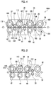
- FIG. 2 is a schematic configuration view showing a slotter device of the present embodiment.
- FIG. 3 is a perspective view showing the slotter device.
- FIG. 4 is a schematic configuration view showing a modification example of the slotter device.
- FIG. 5 is a schematic view of the slotter device showing an arrangement of slotter knives when a single box sheet is processed.
- FIG. 6 is a plan view showing the single box sheet.
- FIG. 7 is a schematic view of the slotter device showing an arrangement of slotter knives when a twin box sheet is processed.
- FIG. 8 is a plan view showing the twin box sheet.
- FIG. 9 is a schematic view for explaining phases of several slotter knives so as to process a communication groove.
- FIG. 10 is a schematic view for explaining phases of several slotter knives so as to process another communication groove.
- FIG. 11 is a schematic view for explaining phases of several slotter knives so as to process still another communication groove.
- FIG. 12 is a schematic view of the slotter device showing an arrangement of slotter knives when a triple box sheet is processed.
- FIG. 13 is a plan view showing the twin box sheet.
- FIG. 1 is a schematic configuration view showing a carton former of the present embodiment.
- a carton former 10 manufactures a corrugated carton (carton body) B by processing a corrugated fiberboard S.
- the carton former 10 includes a sheet feeding section 11 , a printing section 21 , a slotter creaser section 31 , a die-cut section 51 , a cutting section 61 , a speed-increasing section 71 , a folding section 81 , and a counter-ejector section 91 which are linearly disposed in a direction D in which the corrugated fiberboard S and the corrugated carton B are transported.
- the corrugated fiberboards S are fed to the printing section 21 one by one at a constant speed.
- the sheet feeding section 11 includes a table 12 , a front stopper 13 , a supply roller 14 , a suction unit 15 , and a feed roll 16 .
- Several corrugated fiberboards S are placed on the table 12 so as to be stacked, and the table 12 is supported so as to be lifted and lowered.
- the front stopper 13 can position the front end position of each of the corrugated fiberboards S stacked on the table 12 , and a gap which allows one corrugated fiberboard S to pass through a portion between the lower end portion of the front stopper 13 and the table 12 is secured.
- Several supply rollers 14 are disposed corresponding to the table 12 in the transport direction D of the corrugated fiberboard S.
- the corrugated fiberboard S located at the lowermost position among several stacked corrugated fiberboards S can be fed forward by the supply rollers 14 .
- the stacked corrugated fiberboards S are suctioned downward, that is, toward the table 12 side or the supply roller 14 side by the suction unit 15 .
- the feed roll 16 can provide the corrugated fiberboard S fed by the supply rollers 14 to the printing section 21 .
- the printing section 21 performs multi-color printing (in the present embodiment, four-color printing) on the surface of the corrugated fiberboard S.
- four printing units 21 A, 21 B, 21 C, and 21 D are disposed in series, and printing can be performed on the surface of the corrugated fiberboard S using four ink colors.
- the printing units 21 A, 21 B, 21 C, and 21 D are approximately similarly configured to each other, and each of the printing units 21 A, 21 B, 21 C, and 21 D includes a printing cylinder 22 , an ink supply roll (anilox roll) 23 , an ink chamber 24 , and a receiving roll 25 .
- a printing die 26 is mounted on the outer peripheral portion of the printing cylinder 22 , and the printing cylinder 22 is rotatably provided.
- the ink supply roll 23 is disposed so as to contact against the printing die 26 in the vicinity of the printing cylinder 22 , and is rotatably provided.
- the ink chamber 24 stores ink and is provided in the vicinity of the ink supply roll 23 .
- the corrugated fiberboard S is interposed between the receiving roll 25 and the printing cylinder 22 , the receiving roll 25 transports the corrugated fiberboard S while applying a predetermined printing pressure to the corrugated fiberboard S, and the receiving roll 25 is rotatably provided so as to face the lower portion of the printing cylinder 22 .
- a pair of upper and lower feed rolls is provided before and after each of the printing units 21 A, 21 B, 21 C, and 21 D.
- the slotter creaser section 31 includes a slotter device 100 (refer to FIG. 2 ) and performs creasing line processing, cutting, slicing, and gluing margin strip processing on the corrugated fiberboard S.
- the slotter creaser section 31 includes first creasing line rolls 32 , second creasing line rolls 33 , a slitter head 34 , first slotter heads 35 , second slotter heads 36 , and third slotter heads 37 .
- the first creasing line rolls 32 are cylindrically formed, and several first (four in the present embodiment) creasing lines rolls 32 are disposed at predetermined intervals in a horizontal direction orthogonal to the transport direction D of the corrugated fiberboard S.
- the second creasing line rolls 33 are cylindrically formed, and several second (four in the present embodiment) creasing lines rolls 33 are disposed at predetermined intervals in the horizontal direction orthogonal to the transport direction D of the corrugated fiberboard S.
- the first creasing line rolls 32 disposed below perform the creasing line processing on a rear surface (lower surface) of the corrugated fiberboard S, and similarly the first creasing line rolls 32 , the second creasing line rolls 33 disposed below perform the creasing line processing on the rear surface (lower surface) of the corrugated fiberboard S.
- Receiving rolls 38 and 39 are provided at upper positions facing the creasing line rolls 32 and 33 so as to be rotatable in synchronization with the creasing line rolls 32 and 33 .
- the first slotter heads 35 are cylindrically formed, and first several (four in the present embodiment) slotter heads 35 are disposed at predetermined intervals in the horizontal direction orthogonal to the transport direction D of the corrugated fiberboard S.
- the first slotter heads 35 are provided to correspond to predetermined positions of the transported corrugated fiberboard S in the width direction and perform slicing and gluing margin strip processing at the predetermined positions of the corrugated fiberboard S.
- the second slotter heads 36 are cylindrically formed, and second several (four in the present embodiment) slotter heads 36 are disposed at predetermined intervals in the horizontal direction orthogonal to the transport direction D of the corrugated fiberboard S.
- the second slotter heads 36 are provided to correspond to predetermined positions of the transported corrugated fiberboard S in the width direction and perform slicing and gluing margin strip processing at the predetermined positions of the corrugated fiberboard S.
- Each of the slitter head 34 and the third slotter heads 37 is cylindrically formed, and several (five in the present embodiment) heads which are one slitter head 34 and four third slotter heads 37 are disposed at predetermined intervals in the horizontal direction orthogonal to the transport direction D of the corrugated fiberboard S.
- One slitter head 34 is configured, is provided to correspond to the end portion of the transported corrugated fiberboard S in the width direction, and can cut the end portion of the corrugated fiberboard S in the width direction.
- Four third slotter heads 37 are configured, are provided to correspond to predetermined positions of the transported corrugated fiberboard S in the width direction, and can perform slicing and gluing margin strip processing at predetermined positions of the corrugated fiberboard S.
- Lower blades 40 are provided at lower positions facing the first slotter heads 35 so as to be rotatable in synchronization with the first slotter heads 35
- lower blades 41 are provided at lower positions facing the second slotter heads 36 so as to be rotatable in synchronization with the second slotter heads 36
- lower blades 42 are provided at lower positions facing the slitter head 34 and the third slotter heads 37 so as to be rotatable in synchronization with the slitter head 34 and the third slotter heads 37 .
- the die-cut section 51 drilling for forming a hand hole is performed on the corrugated fiberboard S.
- the die-cut section 51 includes a pair of upper and lower feed pieces 52 , an anvil cylinder 53 , and a knife cylinder 54 .
- the feed pieces 52 are rotatably provided such that the corrugated fiberboard S is transported in a state where the corrugated fiberboard S is interposed between the upper portion and the lower portion.
- Each of the anvil cylinder 53 and the knife cylinder 54 is cylindrically formed, and the anvil cylinder 53 and the knife cylinder 54 are rotatable in synchronization with each other by a drive device (not shown).
- a head and a die are provided at a predetermined position on the outer peripheral portion of the knife cylinder 54 while an anvil is formed on the outer peripheral portion of the anvil cylinder 53 .
- the corrugated fiberboard S is cut to be two corrugated fiberboards at an intermediate position in the transport direction D by the cutting section 61 .
- the cutting section 61 includes a pair of upper and lower feed pieces 62 and a pair of upper and lower cutting rolls 63 and 64 .
- the feed pieces 62 are rotatably provided such that the corrugated fiberboard S is transported in a state where the corrugated fiberboard S is interposed between the upper portion and the lower portion.
- Each of the cutting rolls 63 and 64 is cylindrically formed, and the cutting rolls 63 and 64 are rotatable in synchronization with each other by a drive device (not shown).
- a cutting blade is fixed to each of the cutting rolls 63 and 64 at a predetermined position of the outer peripheral portion of each of the cutting rolls 63 and 64 .
- the speed-increasing section 71 increases a speed of the cut corrugated fiberboard S, and a predetermined transport interval between the transported corrugated fiberboards S is secured by the speed-increasing section 71 .
- the speed-increasing section 71 includes a pair of upper and lower transport belts 72 and 73 .
- the transport belts 72 and 73 can be rotated by a drive device (not shown) in synchronization with the drive device such that the corrugated fiberboard S is transported in a state where the corrugated fiberboard S is interposed between the upper portion and the lower portion.
- the transport speed of the corrugated fiberboard S in the speed-increasing section 71 is set to a faster speed than the transport speed of the corrugated fiberboard S until the cutting section 61 .
- the folding section 81 the corrugated fiberboard S is folded while moving in the transport direction D, and both end portions of the corrugated fiberboard S in the width direction are joined to each other so as to form a flat corrugated carton B.
- the folding section 81 includes an upper transport belt 82 , lower transport belts 83 and 84 , and a forming device 85 .
- the upper transport belt 82 and the lower transport belts 83 and 84 transport the corrugated fiberboard S and the corrugated carton B in a state of being interposed between the upper portion and the lower portion.
- the forming device 85 includes a pair of right and left forming belts, and end portions of the corrugated fiberboard S in the width direction is folded while being bent downward by the forming belts.
- the folding section 81 includes a gluing device 86 .
- the gluing device 86 includes a glue gun, glue is ejected at a predetermined timing by the glue gun, and gluing can be applied to a predetermined position of the corrugated fiberboard S.
- the counter-ejector section 91 In the counter-ejector section 91 , after the corrugated cartons B are stacked while being counted, the corrugated cartons B are sorted into a predetermined number of batches, and thereafter, the sorted corrugated cartons B are discharged.
- the counter-ejector section 91 includes a hopper device 92 .
- the hopper device 92 includes an elevator 93 on which corrugated cartons B are stacked and which can be lifted and lowered, and a front stopper and an angle arrangement plate are provided in the elevator 93 .
- an ejection conveyor 94 is provided below the hopper device 92 .
- FIG. 13 is a plan view showing a twin box sheet.
- the corrugated fiberboard (twin box sheet) S is formed by gluing a corrugating core forming a waveform between a front liner and a rear liner.
- four folding lines 301 , 302 , 303 , and 304 are formed in the pre-process of the carton former 10 .
- the folding lines 301 , 302 , 303 , and 304 are used for folding a flap when the corrugated carton B manufactured by the carton former 10 is assembled later.
- the corrugated fiberboard S is stacked on the table 12 of the sheet feeding section 11 .
- the corrugated fiberboard S is supplied to the printing section 21 on a predetermined velocity by the pair of feed rolls 16 .
- ink is supplied from the ink chamber 24 to the surface of the ink supply roll 23 in each of the printing units 21 A, 21 B, 21 C, and 21 D, and if the printing cylinder 22 and the ink supply roll 23 rotate, the ink on the surface of the ink supply roll 23 is transferred to the printing die 26 .
- the corrugated fiberboard S is transported to a portion between the printing cylinder 22 and the receiving roll 25 , the corrugated fiberboard S is interposed between the printing die 26 and the receiving roll 25 , and a printing pressure is applied to the corrugated fiberboard S so as to perform printing on the surface of the corrugated fiberboard S.
- the printed corrugated fiberboard S is transported to the slotter creaser section 31 by the feed rolls.
- creasing lines 312 , 313 , 314 , and 315 are formed on the rear surface (rear liner) side of the corrugated fiberboard S.
- the creasing lines 312 , 313 , 314 , and 315 are formed on the rear surface (rear liner) side of the corrugated fiberboard S again.
- grooves 322 a , 322 b , 322 c , 322 d , 323 a , 323 b , 323 c , 323 d , 324 a , 324 b , 324 c , and 324 d are formed at the positions of the creasing lines 312 , 313 , and 314 .
- end portions 325 a , 325 b , 325 c , and 325 d are cut at the position of the creasing line 315 , and gluing margin strips 326 a and 326 b are formed.
- the grooves 322 d , 323 d , and 324 d are formed when the corrugated fiberboard S passes through the first slotter heads 35
- the grooves 322 a , 323 a , and 324 a are formed, when the corrugated fiberboard S passes through the third slotter heads 37
- the grooves 322 b , 322 c , 323 b , 323 c , 324 b , and 324 c are communication grooves 322 , 323 , and 324 , and the grooves 322 a , 322 d , 323 a , 323 d , 324 a , and 324 d are opening grooves. Thereafter, as shown in FIG. 1 , the corrugated fiberboard S is transported to the die-cut section 51 .
- the corrugated fiberboard S is cut at a cutting position 331 . Accordingly, the corrugated fiberboard S is cut to be the corrugated fiberboard S 1 in which the grooves 322 a , 322 b , 323 a , 323 b , 324 a , and 324 b and the gluing margin strip 326 a are formed, and the corrugated fiberboard S 2 in which the grooves 322 c , 322 d , 323 c , 323 d , 324 c , and 324 d and the gluing margin strip 326 b are formed.
- the corrugated fiberboards S 1 and S 2 are sequentially transported to the speed-increasing section 71 .
- the cut corrugated fiberboards S 1 and S 2 are transported while being interposed between the upper and lower transport belts 72 and 73 .
- the corrugated fiberboards S 1 and S 2 are transported at a transport speed which is increased from the transport speed of the cutting section 61 , a predetermined transport interval is formed between the corrugated fiberboards S 1 and S 2 . Thereafter, the corrugated fiberboard S is transported to the folding section 81 .
- the folding section 81 glue is applied to the gluing margin strip 326 a ( 326 b ) by the gluing device 86 while the corrugated fiberboard S 1 (S 2 ) is moved in the transport direction D by the upper transport belt 82 and the lower transport belts 83 and 84 , and thereafter, the corrugated fiberboards S 1 (S 2 ) is folded downward by the forming device 85 with the creasing lines 312 and 314 as base points.
- the corrugated carton B is fed to the hopper device 92 , the tip portion of the corrugated carton B in the transport direction D abuts on the front stopper, and the corrugated cartons B is stacked on the elevator 93 in a state of being arranged by the angle arrangement plate.
- the elevator 93 is lowered, a predetermined number of corrugated cartons B become one batch, are discharged by the ejection conveyor 94 , and are fed to the post-process of the carton former 10 .
- FIG. 2 is a schematic configuration view showing the slotter device of the present embodiment
- FIG. 3 is a perspective view showing the slotter device.
- the slotter creaser section 31 includes the slotter device 100 .
- the slotter device 100 performs creasing line processing, cutting, slicing, and gluing margin strip processing on the corrugated fiberboard S.
- the slotter device 100 is configured of the first creasing line rolls 32 , the receiving rolls 38 , the second creasing line rolls 33 , the receiving rolls 39 , the first slotter heads (first upper slotter heads) 35 , the first lower blades (first lower slotter heads) 40 , the second slotter heads (second upper slotter heads) 36 , the second lower blades (second lower slotter heads) 41 , the slitter head 34 , the third slotter heads (third upper slotter head) 37 , and the third lower blades (third lower slotter heads) 42 .
- each end portion is rotatably supported by a frame (not shown), the four first creasing line rolls 32 are fixed to the lower roll shaft 101 at predetermined intervals in an axial direction, and the four receiving rolls 38 are fixed to the upper roll shaft 102 at predetermined intervals in an axial direction.
- each end portion is rotatably supported by the frame (not shown)
- the four second creasing line rolls 33 are fixed to the lower roll shaft 103 at predetermined intervals in an axial direction
- the four receiving rolls 39 are fixed to the upper roll shaft 104 at predetermined intervals in an axial direction.
- each first creasing line roll 32 and each receiving roll 38 are disposed to face each other vertically
- each second creasing line roll 33 and each receiving roll 39 are disposed to face each other vertically
- each second creasing line roll 33 is disposed with a predetermined gap in a horizontal direction on the downstream of each first creasing line roll 32 .
- the first creasing line rolls 32 and the second creasing line rolls 33 are disposed at the same position as each other in the axial directions of the roll shafts 101 and 103 , and diameters of the second creasing line rolls 33 are set to be smaller than diameters of the first creasing line rolls 32 .
- the first creasing line rolls 32 and the receiving rolls 38 are disposed to face each other vertically, and if the corrugated fiberboard S enters portions between the first creasing line rolls 32 and the receiving rolls 38 , the corrugated fiberboard S is interposed between the outer peripheral portions of the first creasing line rolls 32 and the outer peripheral portions of the receiving rolls 38 , and creasing lines are formed on the lower surface of the corrugated fiberboard S when the corrugated fiberboard S passes through the portions between the outer peripheral portions of the first creasing line rolls 32 and the outer peripheral portions of the receiving rolls 38 .
- the second creasing line rolls 33 and the receiving rolls 39 are disposed to face each other vertically, and if the corrugated fiberboard S enters portions between the second creasing line rolls 33 and the receiving rolls 39 , the corrugated fiberboard S is interposed between the outer peripheral portions of the second creasing line rolls 33 and the outer peripheral portions of the receiving rolls 39 , and creasing lines are formed on the lower surface of the corrugated fiberboard S again when the corrugated fiberboard S passes through the portions between the outer peripheral portions of the second creasing line rolls 33 and the outer peripheral portions of the receiving rolls 39 . In this case, since the first creasing line roll 32 and the second creasing line roll 33 roll at the same position, one creasing line is formed on the corrugated fiberboard S.
- each end portion is rotatably supported by the frame (not shown)
- the four first slotter heads 35 ( 35 A and 35 B) and one feed roller 43 are fixed to the upper slotter shaft 105 at predetermined intervals in an axial direction
- the four first lower blades 40 and one feed roller 44 are fixed to the lower slotter shaft 106 at predetermined intervals in an axial direction.
- the four first lower blades 40 are disposed to correspond to the four first slotter heads 35 vertically and the feed rollers 43 and 44 are disposed vertically.
- each end portion is rotatably supported by the frame (not shown), the four second slotter heads 36 ( 36 A and 36 B) and one feed roller 45 are fixed to the upper slotter shaft 107 at predetermined intervals in an axial direction, and the four second lower blades 41 and one feed roller 46 are fixed to the lower slotter shaft 108 at predetermined intervals in an axial direction.
- each end portion is rotatably supported by the frame (not shown), one slitter head 34 and the four third slotter heads ( 37 A and 37 B) are fixed to the upper slotter shaft 109 at predetermined intervals in an axial direction, and the five third lower blades 42 are fixed to the lower slotter shaft 110 at predetermined intervals in an axial direction.
- a first slotter knife 112 ( 112 A) and a second slotter knife 113 ( 113 A) are mounted on the outer peripheral portion of each of the three first slotter heads 35 A, and a first slotter knife 112 ( 112 B) and a second slotter knife 113 ( 113 B) are mounted on the outer peripheral portion of the one first slotter head 35 B.
- a third slotter knife 115 ( 115 A) and a fourth slotter knife 116 ( 116 A) are mounted on the outer peripheral portion of each of the three second slotter heads 36 A, and a third slotter knife 115 ( 115 B) and a fourth slotter knife 116 ( 116 B) are mounted on the outer peripheral portion of the one second slotter head 36 B.
- a slitter knife 111 is mounted on the outer peripheral portion of one slitter head 34
- a fifth slotter knife 118 ( 118 A) and a sixth slotter knife 119 ( 119 A) are mounted on the outer peripheral portion of each of the three third slotter heads 37 A
- a fifth slotter knife 118 ( 118 B) and a sixth slotter knife 119 ( 119 B) are mounted on the outer peripheral portion of the one third slotter head 37 B.
- the slitter head 34 is used as a head for cutting an end portion which cuts one end portion of the corrugated fiberboard S in the width direction, and in FIG. 13 , the slitter knife 111 can cut the end portions 321 a and 321 b at the cutting position 311 .
- the slitter knife 111 is provided on the entire circumference of the slitter head 34 .
- the three first slotter heads 35 A, the three second slotter heads 36 A, and the three third slotter heads 37 A are used for slicing to form grooves on the corrugated fiberboard S in the transport direction D, and in FIG. 13 , can form the grooves 322 a , 322 b , 322 c , 322 d , 323 a , 323 b , 323 c , 323 d , 324 a , 324 b , 324 c , and 324 d .
- the first slotter knife 112 A and the second slot knife 113 A are provided on a portion of each of the first slotter heads 35 A in the circumferential direction to be arranged in the circumferential direction.
- the third slotter knife 115 A and the fourth slot knife 116 A are provided on a portion of each of the second slotter heads 36 A in the circumferential direction to be arranged in the circumferential direction.
- the fifth slotter knife 118 A and the sixth slot knife 119 A are provided on a portion of each of the third slotter heads 37 A in the circumferential direction to be arranged in the circumferential direction.
- the one first slotter head 35 B, the one second slotter head 36 B, and the one third slotter head 37 B are disposed on the end portions of the slotter shafts 105 , 107 , and 109 , are used for gluing margin strip processing by which the other end portion of the corrugated fiberboard S in the width direction is cut to form a gluing margin strip, and in FIG. 13 , can cut the end portions 325 a , 325 b , 325 c , and 325 d to form the gluing margin strips 326 a and 326 b .
- the first slotter knife 112 B and the second slot knife 113 B are provided on a portion of the first slotter head 35 B in the circumferential direction to be arranged in the circumferential direction.
- the third slotter knife 115 B and the fourth slot knife 116 B are provided on a portion of the second slotter head 36 B in the circumferential direction to be arranged in the circumferential direction.
- the fifth slotter knife 118 B and the sixth slot knife 119 B are provided on a portion of the third slotter head 37 B in the circumferential direction to be arranged in the circumferential direction.
- each of the slotter knives 112 B, 113 B, 115 B, 116 B, 118 B, and 119 B is configured of a first cutting edge and a second cutting edge which are disposed in a direction approximately orthogonal to each other.
- the first cutting edge is mounted on each of the slotter heads 35 B, 36 B, and 37 B in the transport direction of the corrugated fiberboard S
- the second cutting edge is mounted on each of the slotter heads 35 B, 36 B, and 37 B in the width direction intersecting the transport direction of the corrugated fiberboard S. Accordingly, the first cutting edge and the second cutting edge are disposed to be formed in an L shape and cut the other end portion of the corrugated fiberboard S in the width direction into an L shape, and in FIG. 13 , can cut the end portions 325 a , 325 b , 325 c , and 325 d.
- first slotter heads 35 ( 35 A and 35 B) and the first lower blades 40 are disposed so as to respectively face each other vertically
- the second slotter heads 36 ( 36 A and 36 B) and the second lower blades 41 are disposed so as to respectively face each other vertically
- the slitter head 34 and the third slotter heads 37 ( 37 A and 37 B) and the third lower blades 42 are disposed so as to respectively face each other vertically.
- first slotter heads 35 are disposed with predetermined gaps in the horizontal direction on the downstream sides of the second creasing line rolls 33
- the second slotter heads 36 are disposed with predetermined gaps in the horizontal direction on the downstream sides of the first slotter heads 35 ( 35 A and 35 B)
- the slitter head 34 and the third slotter heads 37 are disposed with predetermined gaps in the horizontal direction on the downstream sides of the second slotter heads 36 ( 36 A and 36 B).
- the second creasing line rolls 33 and the first slotter heads 35 ( 35 A and 35 B) are disposed at the same position as each other in the axial directions of the shafts 103 and 105
- the first slotter heads 35 ( 35 A and 35 B) and the second slotter heads 36 ( 36 A and 36 B) are disposed at the same position as each other in the axial directions of the slotter shafts 105 and 107
- the second slotter heads 36 ( 36 A and 36 B) and the third slotter heads 37 ( 37 A and 37 B) are disposed at the same position as each other in the axial directions of the slotter shafts 107 and 109 .
- the roll shafts 101 , 102 , 103 , and 104 and the slotter shafts 105 and 106 are drivingly connected to a first drive device 121 , and the creasing line rolls 32 and 33 , the receiving rolls 38 and 39 , the first slotter heads 35 , and the lower blades 40 can be drivingly rotated in synchronization with each other by the first drive device 121 .
- the first drive device 121 , the roll shafts 101 , 102 , 103 , and 104 , and the slotter shafts 105 and 106 are drivingly connected to each other by gears (not shown).
- the slotter shafts 107 and 108 are drivingly connected to a second drive device 122 , and the second slotter heads 36 and the lower blades 41 can be drivingly rotated by the second drive device 122 .
- the slotter shafts 109 and 110 are drivingly connected to a third drive device 123 , and the third slotter heads 37 and the lower blades 42 can be drivingly rotated by the third drive device 123 .
- Each of the drive devices 121 , 122 , and 123 is connected to a motor driver (not shown) and the motor driver is connected to a control device.
- a position sensor which detects the position of the corrugated fiberboard S is provided in the sheet feeding section 11 , and the control device controls the drive devices 121 , 122 , and 123 based on the detection results of the position sensor.
- the slotter device 100 is configured of the first creasing line rolls 32 , the receiving rolls 38 , the second creasing line rolls 33 , the receiving rolls 39 , the slitter head 34 , the first slotter heads 35 , the first lower blades 40 , the second slotter heads 36 , the second lower blades 41 , the third slotter heads 37 , and the third lower blades 42 .
- the slotter device 100 is not limited to this configuration.
- FIG. 4 is a schematic configuration view showing a modification example of the slotter device.
- a slotter device 100 A is configured of the first creasing line rolls 32 , the receiving rolls 38 , the second creasing line rolls 33 , the receiving rolls 39 , the first slotter heads 35 , the first lower blades 40 , a pair of upper and lower first feed pieces (transport unit) 131 , the second slotter heads 36 , the second lower blades 41 , a pair of upper and lower second feed pieces (transport unit) 132 , the slitter head 34 , the third slotter heads 37 , and the third lower blades 42 .
- slotter knives 112 , 113 , 115 , 116 , 118 , and 119 mounted on the slotter heads 35 , 36 , and 37 will be described in detail.
- each of the slotter knives 112 , 113 , 115 , 116 , 118 , and 119 are mounted on the outer peripheral portion of each of the slotter heads 35 , 36 , and 37 , and each of outer edges of the slotter knives is formed in an arc shape.
- the first slotter knives 112 form the grooves 322 d , 323 d , 324 d , which are opening grooves, on the upstream end portion of the corrugated fiberboard S in the transport direction D, and cut the end portion 325 d .
- the sixth slotter knives 119 form the grooves 322 a , 323 a , 324 a , which are opening grooves, on the downstream end portion of the corrugated fiberboard S in the transport direction D, and cut the end portion 325 a .
- At least two slotter knives of the second slotter knife 113 , the third slotter knife 115 , the fourth slotter knife 116 , and the fifth slotter knife 118 form communication grooves 322 , 323 , and 324 (grooves 322 b , 322 c , 323 b , 323 c , 324 b , and 324 c ) at the intermediate portion of the corrugated fiberboard S in the transport direction D, and cut the end portions 325 b and 325 c.
- the circumferential length of the first slotter knife 112 is set to be longer than the circumferential length of the second slotter knife 113 .
- the circumferential length of the sixth slotter knife 119 is set to be longer than the circumferential length of the fifth slotter knife 118 .
- the circumferential length of the first slotter knife 112 and the circumferential length of the sixth slotter knife 119 are set to be the same as each other, and the circumferential length of the second slotter knife 113 and the circumferential length of the fifth slotter knife 118 are set to be the same as each other.
- the circumferential length of the third slotter knife 115 is set to be longer than the circumferential length of the fourth slotter knife 116 .
- the circumferential length of each of the second slotter knife 113 and the fifth slotter knife 118 is set to be shorter than the circumferential length of the third slotter knife 115 and is set to be longer than the circumferential length of the fourth slotter knife 116 .
- the second slotter knife 113 is fixed to the outer peripheral portion of the first slotter head 35
- the third slotter knife 115 is fixed to the outer peripheral portion of the second slotter head 36
- the sixth slotter knife 119 is fixed to the outer peripheral portion of the third slotter head 37
- the first slotter knife 112 is mounted on the outer peripheral portion of the first slotter head 35 so as to be adjustable in position in the circumferential direction
- the fourth slotter knife 116 is mounted on the outer peripheral portion of the second slotter head 36 so as to be adjustable in position in the circumferential direction
- the fifth slotter knife 118 is mounted on the outer peripheral portion of the third slotter head 37 so as to be adjustable in position in the circumferential direction.
- the fixing is performed by bolt-fastening, welding, or the like and the position being adjustable means that the position is freely movable in the circumferential direction by a rail or an elongated hole.
- FIG. 5 is a schematic view of the slotter device showing an arrangement of slotter knives when the single box sheet is processed and FIG. 6 is a plan view showing the single box sheet.
- the position is adjusted such that the first slotter knife 112 comes into contact with the fixed second slotter knife 113 in the first slotter head 35
- the position is adjusted such that the fourth slotter knife 116 comes into contact with the fixed third slotter knife 115 in the second slotter head 36
- the position is adjusted such that the fifth slotter knife 118 comes into contact with the fixed sixth slotter knife 119 in the third slotter head 37 .
- the drive of the second slotter head 36 is stopped while the first slotter head 35 and the third slotter head 37 drivingly rotate.
- folding lines 401 and 402 are formed on the corrugated fiberboard (single box sheet) S 0 in the pre-process.
- first creasing line rolls 32 creasing lines 411 and 412 are formed, and when corrugate fiberboard S 0 passes through the second creasing line rolls 33 , the creasing lines 411 and 412 are formed again.
- second slotter knife 113 A a groove 421 b is formed at the position of the creasing line 411 by the first slotter knife 112 A (second slotter knife 113 A).
- skip feed processing can be performed.
- This skip feed processing is applied to slicing with respect to a corrugated fiberboard S 0 having a relatively larger size in the transport direction than a general corrugated fiberboard. That is, as shown in FIG. 1 , in the sheet feeding section 11 , when the corrugated fiberboard S stacked on the table 12 is fed, the corrugated fiberboard S is fed every other time with respect to the feeding timing of a general corrugated fiberboard S. In general, the sheet feeding section 11 feeds one corrugated fiberboard S with respect to one rotation of the printing cylinder 22 in the printing section 21 .
- the sheet feeding section 11 feeds one corrugated fiberboard S with respect to two rotations of the printing cylinder 22 in the printing section 21 .
- the corrugated fiberboard S can be appropriately transported while the end portions of the front and rear corrugated fiberboards S do not come into contact with each other.
- FIG. 7 is a schematic view of the slotter device showing an arrangement of slotter knives when the twin box sheet is processed
- FIG. 8 is a plan view showing the twin box sheet
- FIG. 9 is a schematic view for explaining phases of several slotter knives so as to process, a communication groove
- FIG. 10 is a schematic view for explaining phases of several slotter knives so as to process another communication groove
- FIG. 11 is a schematic view for explaining phases of several slotter knives so as to process another communication groove.
- the first slotter knife 112 is adjusted to be positioned at a predetermined position with respect to the fixed second slotter knife 113 in the first slotter head 35
- the fourth slotter knife 116 is adjusted to be positioned at a predetermined position with respect to the fixed third slotter knife 115 in the second slotter head 36
- the fifth slotter knife 118 is adjusted to be positioned at a predetermined position with respect to the fixed sixth slotter knife 119 in the third slotter head 37 .
- the first slotter head 35 , the second slotter head 36 , and the third slotter head 37 are drivingly rotated.
- folding lines 301 , 302 , 303 , and 304 are formed on the corrugated fiberboard (twin box sheet) S in the pre-process.
- the creasing lines 314 and 315 are formed when the corrugated fiberboard S passes through the first creasing line roll 32 , and the creasing lines 314 and 315 are formed again when the corrugated fiberboard S passes through the second creasing line roll 33 .
- the groove 324 d is formed at the position of the creasing line 314 by the first slotter knife 112 A and a portion of the groove 324 c is formed at the position of the creasing line 314 by the second slotter knife 113 A.
- the end portion 325 d is cut at the position of the creasing line 315 by the first slotter knife 112 B and a portion of the end portion 325 c is cut by the second slotter knife 113 B to form the gluing margin strip 326 b.
- the processing positions are described in order of the slotter head 35 , 36 , and 37 .
- the slotter heads 35 , 36 , and 37 approximately simultaneously performs cutting on the corrugated fiberboard S.
- combinations of the slotter knives which form the grooves 324 b and 324 c to cut the end portions 325 b and 325 c are not limited to the above-described combinations.
- slicing is performed on the twin box sheet (corrugated fiberboard) S having a relatively short length (groove length) in the transport direction, as shown in FIG.
- the grooves 324 b and 324 c are formed on the corrugated fiberboard S and the end portions 325 b and 325 c are cut using the second slotter knife 113 and the third slotter knife 115 . That is, since the rotation phases of the two slotter knives 113 and 115 is continued so as to partially overlap each other with respect to the corrugated fiberboard S at the positions of the slotter heads 35 , 36 , and 37 , by cutting the grooves 324 b and 324 c stepwise, finally, it is possible to form the communication groove 324 , and it is possible to cut the end portions 325 b and 325 c stepwise.
- the grooves 324 b and 324 c are formed on the corrugated fiberboard S and the end portions 325 b and 325 c are cut using the second slotter knife 113 , the fourth slotter knife 116 , and the fifth slotter knife 118 .
- FIG. 12 is a schematic view of the slotter device showing an arrangement of slotter knives when the triple box sheet is processed.
- the slotter knives 112 , 116 , and 118 are adjusted to be positioned at predetermined positions with respect to the fixed slotter knives 113 , 115 , and 119 in the slotter heads 35 , 36 , and 37 .
- the first slotter head 35 , the second slotter head 36 , and the third slotter head 37 are drivingly rotated.
- folding lines 501 , 502 , 503 , 504 , 505 , and 506 are formed on the corrugated fiberboard (triple box sheet) S (S 1 , S 2 , and S 3 ) in the pre-process.
- the creasing lines 511 and 512 are formed when the corrugated fiberboard S passes through the first creasing line roll 32 , and the creasing lines 511 and 512 are formed again when the corrugated fiberboard S passes through the second creasing line roll 33 .
- the groove 521 f is formed at the position of the creasing line 511 by the first slotter knife 112 A and grooves 521 d and 521 e are partially formed at the position of the creasing line 511 by the second slotter knife 113 A.
- an end portion 522 f is cut at the position of the creasing line 512 by the first slotter knife 112 B and end portions 522 d and 522 e are partially cut by the second slotter knife 113 B to form a gluing margin strip 523 c.
- the grooves 521 d and 521 e are completely formed at the position of the creasing line 511 by the fourth slotter knife 116 A and the grooves 521 b and 521 c are partially formed at the position of the creasing line 511 by the third slotter knife 115 A.
- the end portions 522 d and 522 e are completely cut at the position of the creasing line 512 by the fourth slotter knife 116 B and the end portions 522 b and 522 c are partially cut by the third slotter knife 115 B to form a gluing margin strip 523 b .
- the first slotter head 35 , the first lower blade 40 , the first slotter knife 112 and the second slotter knife 113 mounted on the outer peripheral portion of the first slotter head 35 , the second slotter head 36 , the second lower blade 41 , the third slotter knife 115 and the fourth slotter knife 116 mounted on the outer peripheral portion of the second slotter head 36 , the third slotter head 37 , the third lower blade 42 , and the fifth slotter knife 118 and the sixth slotter knife 119 mounted on the outer peripheral portion of the third slotter head 37 are provided.
- the corrugated fiberboards S 1 and S 2 having several sheets connected to each other in the length in the transport direction are manufactured, it is possible to perform slicing or gluing margin strip processing, and in this case, it is possible to easily adjust the lengths of grooves or gluing margin strips to be processed by combining the several slotter knives 112 , 113 , 115 , 116 , 118 , and 119 , the grooves or gluing margin strips having lengths different from each other can be processed, and it is possible to improve versatility.
- the first slotter knife 112 and the sixth slotter knife 119 can form an opening groove on each end portion of the corrugated fiberboard S in a transport direction
- the second slotter knife 113 , the third slotter knife 115 , the fourth slotter knife 116 , and the fifth slotter knife 118 can form a communication groove on an intermediate portion of the corrugated fiberboard S in the transport direction. Accordingly, it is possible to easily form the grooves or the gluing margin strips having lengths different from each other by selecting a slotter knife to be used among the second, third, fourth, and fifth slotter knives 113 , 115 , 116 , and 118 .
- the circumferential length of each of the first slotter knife 112 and the sixth slotter knife 119 is set to be longer than a circumferential length of each of the second slotter knife 113 and the fifth slotter knife 118 .
- a circumferential length of the third slotter knife 115 is set to be longer than a circumferential length of the fourth slotter knife 116 . Accordingly, it is possible to easily form the communication groove having a desired length by providing the slotter knives 115 and 116 having the circumferential lengths different from each other on the second slotter head 36 .
- the circumferential length of each of the second slotter knife 113 and the fifth slotter knife 118 is set to be shorter than the circumferential length of the third slotter knife 115 and to be longer than the circumferential length of the fourth slotter knife 116 . Accordingly, by setting the circumferential lengths of the second, third, fourth, and fifth slotter knives 113 , 115 , 116 , and 118 to be different from each other, it is possible to easily form the communication groove having a desired length by combining the four slotter knives 113 , 115 , 116 , and 118 .
- the second slotter knife 113 , the third slotter knife 115 , and the sixth slotter knife 119 are respectively fixed to the slotter heads 35 , 36 , and 37
- the first slotter knife 112 , the fourth slotter knife 116 , and the fifth slotter knife 118 are respectively mounted on the slotter heads 35 , 36 , and 37 so as to be adjustable in position in a circumferential direction.
- the slotter heads 35 , 36 , and 37 are connected to drive devices 121 , 122 , and 123 which are driving rotated individually. Accordingly, it is possible to easily form the communication groove having a desired length by stopping the second slotter head 36 on which unused slotter knives 115 and 116 are mounted.
- the first and second feed pieces 131 and 132 are provided between the first slotter head 35 , the second slotter head 36 , and the third slotter head 37 . Accordingly, even when the corrugated fiberboard S which is short in the transport direction is provided, it is possible to appropriately transport the corrugated fiberboard S so as to process the corrugated fiberboard S, and it is possible to improve reliability.
- the sheet slicing method of the present embodiment includes: a step of forming a first opening groove on the end portion on the downstream side in the transport direction of the corrugated fiberboard S by the first slotter knife 112 mounted on the first slotter head 35 , a step of forming a communication groove on the intermediate portion of the corrugated fiberboard S in the transport direction by at least two slotter knives of the second slotter knife 113 mounted on the first slotter head 35 , the third slotter knife 115 and the fourth slotter knife 116 mounted on the second slotter head 36 , and the fifth slotter knife 118 mounted on the third slotter head 37 , and a step of forming a second opening groove on the end portion on the upstream side in the transport direction of the corrugated fiberboard S by the sixth slotter knife 119 mounted on the third slotter head 37 .
- the second slotter head 36 when slicing is performed on the corrugated fiberboard S 0 having one sheet, the second slotter head 36 is stopped, the first opening groove is formed by at least one of the slotter knives 112 and 113 of the first slotter head 35 , and the second opening groove is formed by at least one of the slotter knives 118 and 119 of the third slotter head 37 . Accordingly, even when the corrugated fiberboard S 0 having one sheet is provided, it is possible to easily form the communication groove having a desired length by stopping the unused second slotter head 36 .
- the sheet feeding section 11 , the printing section 21 , the slotter creaser section 31 , the die-cut section 51 , the cutting section 61 , the speed-increasing section 71 , the folding section 81 , and the counter-ejector section 91 are provided, and the slotter device 10 is provided in the slotter creaser section 31 .
- circumferential lengths of the slotter knives 112 , 113 , 115 , 116 , 118 , and 119 described in the above-described embodiment are not limited to the embodiment, and the circumferential lengths may be appropriately set according to the size, the shape, or the like of the corrugated fiberboard S to be processed.
- the carton former 10 is configured of the sheet feeding section 11 , the printing section 21 , the slotter creaser section 31 , the die-cut section 51 , the cutting section 61 , the speed-increasing section 71 , the folding section 81 , and the counter-ejector section 91 .
- the die-cut section 51 may not be omitted.
- the carton former 10 may be configured of the sheet feeding section 11 , the printing section 21 , and the slotter creaser section 31 .
- the cutting section 61 or the speed-increasing section 71 may be omitted, and the corrugated fiberboard S may be cut in a post-process in which the corrugated fiberboard S is discharged from the carton former 10 .
Landscapes
- Life Sciences & Earth Sciences (AREA)
- Forests & Forestry (AREA)
- Engineering & Computer Science (AREA)
- Mechanical Engineering (AREA)
- Making Paper Articles (AREA)
Applications Claiming Priority (3)
| Application Number | Priority Date | Filing Date | Title |
|---|---|---|---|
| JP2015-028901 | 2015-02-17 | ||
| JP2015028901A JP6529778B2 (ja) | 2015-02-17 | 2015-02-17 | スロッタ装置及びシートの溝切り加工方法、製函機 |
| PCT/JP2015/074954 WO2016132576A1 (ja) | 2015-02-17 | 2015-09-02 | スロッタ装置及びシートの溝切り加工方法、製函機 |
Publications (2)
| Publication Number | Publication Date |
|---|---|
| US20180029244A1 US20180029244A1 (en) | 2018-02-01 |
| US10800061B2 true US10800061B2 (en) | 2020-10-13 |
Family
ID=56692047
Family Applications (1)
| Application Number | Title | Priority Date | Filing Date |
|---|---|---|---|
| US15/551,034 Active 2036-03-12 US10800061B2 (en) | 2015-02-17 | 2015-09-02 | Slotter device, sheet slicing method, and carton former |
Country Status (6)
| Country | Link |
|---|---|
| US (1) | US10800061B2 (ja) |
| EP (1) | EP3260254B1 (ja) |
| JP (1) | JP6529778B2 (ja) |
| KR (1) | KR102064655B1 (ja) |
| CN (1) | CN107249835B (ja) |
| WO (1) | WO2016132576A1 (ja) |
Cited By (5)
| Publication number | Priority date | Publication date | Assignee | Title |
|---|---|---|---|---|
| US11318698B2 (en) * | 2016-10-12 | 2022-05-03 | Emba Holding Aktiebolag | Dual box slotter |
| US11331824B2 (en) * | 2016-06-29 | 2022-05-17 | Valinge Innovation Ab | Method and device for inserting a tongue |
| US20220152969A1 (en) * | 2019-03-08 | 2022-05-19 | Bobst Lyon | Line for manufacturing packagings in the form of folding boxes |
| US20220176669A1 (en) * | 2019-03-08 | 2022-06-09 | Bobst Lyon | Unit for forming a plate element for manufacturing folding boxes |
| US11618177B1 (en) | 2022-04-12 | 2023-04-04 | Bradley W Boesel | Orbital knife |
Families Citing this family (12)
| Publication number | Priority date | Publication date | Assignee | Title |
|---|---|---|---|---|
| JP6818516B2 (ja) * | 2016-11-08 | 2021-01-20 | 三菱重工機械システム株式会社 | 送りロール移動装置、ナイフシリンダ、ロータリダイカッタ並びに製函機 |
| JP6852874B2 (ja) * | 2016-12-27 | 2021-03-31 | 株式会社Isowa | 段ボールシート製函機 |
| JP6852875B2 (ja) * | 2016-12-27 | 2021-03-31 | 株式会社Isowa | 段ボールシート製函機 |
| US10821697B2 (en) | 2016-12-27 | 2020-11-03 | Kabushiki Kaisha Isowa | Corrugated paperboard box making machine |
| JP2018183839A (ja) * | 2017-04-26 | 2018-11-22 | 三菱重工機械システム株式会社 | 切断加工用刃物及びスロッタ装置並びに製函機 |
| CN107053759B (zh) * | 2017-05-12 | 2023-06-13 | 广州荣欣包装制品有限公司 | 一种纸盒加工吸尘装置 |
| WO2019013188A1 (ja) * | 2017-07-14 | 2019-01-17 | 株式会社江東彫刻 | ロールカッタ装置 |
| EP3495133B1 (en) * | 2017-09-27 | 2021-06-23 | Mitsubishi Heavy Industries Machinery Systems, Ltd. | Box making machine and method for adjusting processing position of corrugated cardboard sheet |
| CN108162485B (zh) * | 2017-11-16 | 2023-05-02 | 江苏力维智能装备有限公司 | 一种智能纸箱裁切机 |
| JP7055724B2 (ja) * | 2018-09-14 | 2022-04-18 | 三菱重工機械システム株式会社 | スロッタ装置、及び、製函機 |
| JP7466320B2 (ja) | 2020-01-31 | 2024-04-12 | 三菱重工機械システム株式会社 | スロッタヘッドおよびスロッタ装置並びに製函機 |
| JP7449719B2 (ja) * | 2020-02-28 | 2024-03-14 | 三菱重工機械システム株式会社 | スリッタ装置、スリッタヘッドの位置決め方法および製函機 |
Citations (32)
| Publication number | Priority date | Publication date | Assignee | Title |
|---|---|---|---|---|
| US1567656A (en) * | 1924-01-19 | 1925-12-29 | Samuel M Langston | Sheet scoring and slotting mechanism |
| US2808106A (en) | 1955-04-27 | 1957-10-01 | Crown Zellerbach Corp | Slotting device |
| US3036486A (en) * | 1958-03-07 | 1962-05-29 | Simonds Saw & Steel Co | Slotting segments with v-shaped cutting portion for corrugated paperboard and the like |
| US3211066A (en) * | 1963-12-03 | 1965-10-12 | Koppers Co Inc | Rotary slotting apparatus |
| US3236137A (en) * | 1964-05-13 | 1966-02-22 | Koppers Co Inc | Cutting blade retention means |
| US3518922A (en) * | 1967-10-23 | 1970-07-07 | Koppers Co Inc | Blank stripping apparatus for rotary cutters |
| US3575091A (en) * | 1969-08-04 | 1971-04-13 | Orchard Container Corp | Cuttings remover for slotting machines |
| US3772953A (en) * | 1970-08-12 | 1973-11-20 | Simon Ltd H | Slotting heads |
| US4003300A (en) * | 1974-09-11 | 1977-01-18 | Molins Machine Company, Inc. | Apparatus having dual slotter shafts |
| US4061063A (en) * | 1976-12-27 | 1977-12-06 | The Procter & Gamble Company | Rotary shear |
| US4167884A (en) * | 1978-05-26 | 1979-09-18 | S&S Corrugated Paper Machinery Co., Inc. | Piggy back slotter blades |
| US4643060A (en) * | 1986-02-03 | 1987-02-17 | Westvaco Corporation | Air cooled slotter and slitter blade cutting edges |
| US5144874A (en) * | 1991-05-20 | 1992-09-08 | Garrett Jimmy R | Rotary cutter knife |
| US5174184A (en) * | 1992-05-18 | 1992-12-29 | Lawrence Paper Company | Slotter head assembly having pneumatically locked slotter blades |
| US5181899A (en) * | 1992-02-14 | 1993-01-26 | Lawrence Paper Company | Adjustable slotter wheel and sheet feeder retrofit apparatus for box blank making machines |
| JP2000313073A (ja) | 1999-04-30 | 2000-11-14 | Banrin Hamono Kk | 段ボールシート製函機のシート角切り機構 |
| JP2002067190A (ja) | 2000-08-29 | 2002-03-05 | Isowa Corp | 段ボールシート製函機のスロッタ |
| JP2003001727A (ja) | 2001-06-21 | 2003-01-08 | Isowa Corp | 段ボールシート製函機 |
| JP2003251713A (ja) | 2002-03-04 | 2003-09-09 | Tsukasaki Akiyoshi | ダンボールシートの製函機に装置されている、罫線及び切り込み装置の加工方法と構造 |
| US7044040B1 (en) * | 2003-03-27 | 2006-05-16 | Sebring Container Corporation | Leading and trailing edge stitch tab scrap strippers |
| US20060156891A1 (en) * | 2003-12-04 | 2006-07-20 | Kinki Knives Industries Ltd., | Cutting tool |
| US20090062098A1 (en) | 2005-04-14 | 2009-03-05 | Hamada Printing Press Co., Ltd. | Creasing device |
| JP2009291992A (ja) | 2008-06-03 | 2009-12-17 | Isowa Corp | 段ボールシート製函機 |
| JP2010142988A (ja) | 2008-12-17 | 2010-07-01 | Isowa Corp | 段ボールシート製函機 |
| CN101873926A (zh) | 2008-07-01 | 2010-10-27 | 三菱重工业株式会社 | 用于生产波纹板片的箱子的方法和装置 |
| CN102529158A (zh) | 2012-02-20 | 2012-07-04 | 广东东方精工科技股份有限公司 | 一种可根据要求调整前后开槽距离的纸板开槽装置 |
| CN202911193U (zh) | 2012-11-30 | 2013-05-01 | 何西 | 一种瓦楞纸板印刷碰线开槽模切机 |
| KR20130059457A (ko) | 2011-01-31 | 2013-06-05 | 미츠비시주코 인사츠시코키카이 가부시키가이샤 | 카운터 이젝터 및 제함기 |
| US20130184133A1 (en) | 2010-09-30 | 2013-07-18 | Mitsubishi Heavy Industries Printing & Packaging Machinery, Ltd. | Defective product removing device for box making machine and box making machine |
| JP2013169687A (ja) | 2012-02-20 | 2013-09-02 | Mitsubishi Heavy Industries Printing & Packaging Machinery Ltd | スロッタ装置及びシートの溝切り加工方法と製函機 |
| CN203666014U (zh) | 2014-01-10 | 2014-06-25 | 东光县精科纸箱机械有限公司 | 一种双刀纸箱开槽机 |
| JP2015027740A (ja) | 2013-07-30 | 2015-02-12 | 株式会社梅谷製作所 | 段ボールシート加工装置 |
Family Cites Families (1)
| Publication number | Priority date | Publication date | Assignee | Title |
|---|---|---|---|---|
| JP6116218B2 (ja) * | 2012-12-07 | 2017-04-19 | 株式会社Isowa | 段ボールシート製函機のシート分離装置、および、シート分離機能を備える段ボールシート製函機 |
-
2015
- 2015-02-17 JP JP2015028901A patent/JP6529778B2/ja active Active
- 2015-09-02 US US15/551,034 patent/US10800061B2/en active Active
- 2015-09-02 KR KR1020177022685A patent/KR102064655B1/ko active IP Right Grant
- 2015-09-02 CN CN201580076184.2A patent/CN107249835B/zh active Active
- 2015-09-02 EP EP15882677.6A patent/EP3260254B1/en active Active
- 2015-09-02 WO PCT/JP2015/074954 patent/WO2016132576A1/ja active Application Filing
Patent Citations (39)
| Publication number | Priority date | Publication date | Assignee | Title |
|---|---|---|---|---|
| US1567656A (en) * | 1924-01-19 | 1925-12-29 | Samuel M Langston | Sheet scoring and slotting mechanism |
| US2808106A (en) | 1955-04-27 | 1957-10-01 | Crown Zellerbach Corp | Slotting device |
| US3036486A (en) * | 1958-03-07 | 1962-05-29 | Simonds Saw & Steel Co | Slotting segments with v-shaped cutting portion for corrugated paperboard and the like |
| US3211066A (en) * | 1963-12-03 | 1965-10-12 | Koppers Co Inc | Rotary slotting apparatus |
| US3236137A (en) * | 1964-05-13 | 1966-02-22 | Koppers Co Inc | Cutting blade retention means |
| US3518922A (en) * | 1967-10-23 | 1970-07-07 | Koppers Co Inc | Blank stripping apparatus for rotary cutters |
| US3575091A (en) * | 1969-08-04 | 1971-04-13 | Orchard Container Corp | Cuttings remover for slotting machines |
| US3772953A (en) * | 1970-08-12 | 1973-11-20 | Simon Ltd H | Slotting heads |
| US4003300A (en) * | 1974-09-11 | 1977-01-18 | Molins Machine Company, Inc. | Apparatus having dual slotter shafts |
| US4061063A (en) * | 1976-12-27 | 1977-12-06 | The Procter & Gamble Company | Rotary shear |
| US4167884A (en) * | 1978-05-26 | 1979-09-18 | S&S Corrugated Paper Machinery Co., Inc. | Piggy back slotter blades |
| US4643060A (en) * | 1986-02-03 | 1987-02-17 | Westvaco Corporation | Air cooled slotter and slitter blade cutting edges |
| US5144874A (en) * | 1991-05-20 | 1992-09-08 | Garrett Jimmy R | Rotary cutter knife |
| US5181899A (en) * | 1992-02-14 | 1993-01-26 | Lawrence Paper Company | Adjustable slotter wheel and sheet feeder retrofit apparatus for box blank making machines |
| US5316538A (en) * | 1992-02-14 | 1994-05-31 | Lawrence Paper Company | Adjustable slotter wheel retrofit apparatus for box blank making machines |
| US5174184A (en) * | 1992-05-18 | 1992-12-29 | Lawrence Paper Company | Slotter head assembly having pneumatically locked slotter blades |
| JP2000313073A (ja) | 1999-04-30 | 2000-11-14 | Banrin Hamono Kk | 段ボールシート製函機のシート角切り機構 |
| JP3197256B2 (ja) | 1999-04-30 | 2001-08-13 | 万林刃物株式会社 | 段ボールシート製函機のシート角切り機構 |
| JP2002067190A (ja) | 2000-08-29 | 2002-03-05 | Isowa Corp | 段ボールシート製函機のスロッタ |
| JP2003001727A (ja) | 2001-06-21 | 2003-01-08 | Isowa Corp | 段ボールシート製函機 |
| JP2003251713A (ja) | 2002-03-04 | 2003-09-09 | Tsukasaki Akiyoshi | ダンボールシートの製函機に装置されている、罫線及び切り込み装置の加工方法と構造 |
| US7044040B1 (en) * | 2003-03-27 | 2006-05-16 | Sebring Container Corporation | Leading and trailing edge stitch tab scrap strippers |
| US20060156891A1 (en) * | 2003-12-04 | 2006-07-20 | Kinki Knives Industries Ltd., | Cutting tool |
| US7631586B2 (en) * | 2003-12-04 | 2009-12-15 | Kinki Knives Industries Ltd. | Cutting tool |
| US20090062098A1 (en) | 2005-04-14 | 2009-03-05 | Hamada Printing Press Co., Ltd. | Creasing device |
| JP2009291992A (ja) | 2008-06-03 | 2009-12-17 | Isowa Corp | 段ボールシート製函機 |
| CN101873926A (zh) | 2008-07-01 | 2010-10-27 | 三菱重工业株式会社 | 用于生产波纹板片的箱子的方法和装置 |
| US20110092351A1 (en) | 2008-07-01 | 2011-04-21 | Mitsubishi Heavy Industries, Ltd. | Method and device for producing box of corrugated board sheet |
| US8579777B2 (en) | 2008-07-01 | 2013-11-12 | Mitsubishi Heavy Industries Printing & Packaging Machinery, Ltd. | Method and device for producing box of corrugated board sheet |
| JP2010142988A (ja) | 2008-12-17 | 2010-07-01 | Isowa Corp | 段ボールシート製函機 |
| US20130184133A1 (en) | 2010-09-30 | 2013-07-18 | Mitsubishi Heavy Industries Printing & Packaging Machinery, Ltd. | Defective product removing device for box making machine and box making machine |
| CN103269849A (zh) | 2010-09-30 | 2013-08-28 | 三菱重工印刷纸工机械有限公司 | 制盒机的不合格品去除装置及制盒机 |
| US20130296151A1 (en) | 2011-01-31 | 2013-11-07 | Mitsubishi Heavy Industries Printing & Packaging Machinery, Ltd | Counter ejector and box former |
| KR20130059457A (ko) | 2011-01-31 | 2013-06-05 | 미츠비시주코 인사츠시코키카이 가부시키가이샤 | 카운터 이젝터 및 제함기 |
| CN102529158A (zh) | 2012-02-20 | 2012-07-04 | 广东东方精工科技股份有限公司 | 一种可根据要求调整前后开槽距离的纸板开槽装置 |
| JP2013169687A (ja) | 2012-02-20 | 2013-09-02 | Mitsubishi Heavy Industries Printing & Packaging Machinery Ltd | スロッタ装置及びシートの溝切り加工方法と製函機 |
| CN202911193U (zh) | 2012-11-30 | 2013-05-01 | 何西 | 一种瓦楞纸板印刷碰线开槽模切机 |
| JP2015027740A (ja) | 2013-07-30 | 2015-02-12 | 株式会社梅谷製作所 | 段ボールシート加工装置 |
| CN203666014U (zh) | 2014-01-10 | 2014-06-25 | 东光县精科纸箱机械有限公司 | 一种双刀纸箱开槽机 |
Non-Patent Citations (8)
| Title |
|---|
| English Translation JP2003-001727A ; Minami, Jiro; B31B001/22. * |
| Extended European Search Report for European Application No. 15882677 dated Nov. 29, 2018; 7pp. |
| International Search Report in International Application No. PCT/JP2015/074954, dated Oct. 13, 2015. |
| Office Action for Japanese Application No. 2015-028901 dated Jan. 29, 2019; 5pp. |
| Office Action for Korean Application No. 10-2017-7022685 dated Apr. 5, 2019; 10pp. |
| Office Action in CN Application No. 201580076184.2, dated Jul. 11, 2018, 10pp. |
| Office Action in Japanese Application No. 2015-028901, dated Jul. 3, 2018, 5pp. |
| Written Opinion in International Application No. PCT/JP2015/074954, dated Oct. 13, 2015. |
Cited By (7)
| Publication number | Priority date | Publication date | Assignee | Title |
|---|---|---|---|---|
| US11331824B2 (en) * | 2016-06-29 | 2022-05-17 | Valinge Innovation Ab | Method and device for inserting a tongue |
| US11318698B2 (en) * | 2016-10-12 | 2022-05-03 | Emba Holding Aktiebolag | Dual box slotter |
| US20220152969A1 (en) * | 2019-03-08 | 2022-05-19 | Bobst Lyon | Line for manufacturing packagings in the form of folding boxes |
| US20220176669A1 (en) * | 2019-03-08 | 2022-06-09 | Bobst Lyon | Unit for forming a plate element for manufacturing folding boxes |
| US11618177B1 (en) | 2022-04-12 | 2023-04-04 | Bradley W Boesel | Orbital knife |
| US11648701B1 (en) | 2022-04-12 | 2023-05-16 | Bradley W Boesel | Orbital knife |
| US11878438B1 (en) | 2022-04-12 | 2024-01-23 | Bradley W Boesel | Orbital knife |
Also Published As
| Publication number | Publication date |
|---|---|
| CN107249835B (zh) | 2019-05-07 |
| CN107249835A (zh) | 2017-10-13 |
| EP3260254B1 (en) | 2020-08-19 |
| EP3260254A1 (en) | 2017-12-27 |
| WO2016132576A1 (ja) | 2016-08-25 |
| JP2016150407A (ja) | 2016-08-22 |
| EP3260254A4 (en) | 2019-01-02 |
| KR102064655B1 (ko) | 2020-01-09 |
| JP6529778B2 (ja) | 2019-06-12 |
| KR20170104577A (ko) | 2017-09-15 |
| US20180029244A1 (en) | 2018-02-01 |
Similar Documents
| Publication | Publication Date | Title |
|---|---|---|
| US10800061B2 (en) | Slotter device, sheet slicing method, and carton former | |
| EP3231594B1 (en) | Slotter head, slotter apparatus, and carton manufacturing machine | |
| US20180370061A1 (en) | Slotter apparatus, and slotter positioning method, carton former, and cardboard sheet | |
| US9833963B2 (en) | Sheet folding device and carton former | |
| EP3450156B1 (en) | Sheet folding device and box-making machine | |
| WO2021153371A1 (ja) | スロッタヘッドおよびスロッタ装置並びに製函機 | |
| US11338535B2 (en) | Sheet folding device and method, and box-making machine | |
| WO2013125349A1 (ja) | スロッタ装置及びシートの溝切り加工方法と製函機 | |
| US20200171776A1 (en) | Sheet folding device and carton folder | |
| JP7449719B2 (ja) | スリッタ装置、スリッタヘッドの位置決め方法および製函機 |
Legal Events
| Date | Code | Title | Description |
|---|---|---|---|
| AS | Assignment |
Owner name: MITSUBISHI HEAVY INDUSTRIES PRINTING & PACKAGING MACHINERY, LTD., JAPAN Free format text: ASSIGNMENT OF ASSIGNORS INTEREST;ASSIGNORS:YAMAMURO, KUNIHIKO;SUGIMOTO, KAZUYA;HATANO, OSAMU;REEL/FRAME:043287/0936 Effective date: 20170623 Owner name: MITSUBISHI HEAVY INDUSTRIES PRINTING & PACKAGING M Free format text: ASSIGNMENT OF ASSIGNORS INTEREST;ASSIGNORS:YAMAMURO, KUNIHIKO;SUGIMOTO, KAZUYA;HATANO, OSAMU;REEL/FRAME:043287/0936 Effective date: 20170623 |
|
| AS | Assignment |
Owner name: MITSUBISHI HEAVY INDUSTRIES MACHINERY SYSTEMS, LTD., JAPAN Free format text: MERGER;ASSIGNOR:MITSUBISHI HEAVY INDUSTRIES PRINTING & PACKAGING MACHINERY, LTD.;REEL/FRAME:044579/0154 Effective date: 20171001 Owner name: MITSUBISHI HEAVY INDUSTRIES MACHINERY SYSTEMS, LTD Free format text: MERGER;ASSIGNOR:MITSUBISHI HEAVY INDUSTRIES PRINTING & PACKAGING MACHINERY, LTD.;REEL/FRAME:044579/0154 Effective date: 20171001 |
|
| STPP | Information on status: patent application and granting procedure in general |
Free format text: NON FINAL ACTION MAILED |
|
| STPP | Information on status: patent application and granting procedure in general |
Free format text: RESPONSE TO NON-FINAL OFFICE ACTION ENTERED AND FORWARDED TO EXAMINER |
|
| STPP | Information on status: patent application and granting procedure in general |
Free format text: FINAL REJECTION MAILED |
|
| STPP | Information on status: patent application and granting procedure in general |
Free format text: NOTICE OF ALLOWANCE MAILED -- APPLICATION RECEIVED IN OFFICE OF PUBLICATIONS |
|
| STPP | Information on status: patent application and granting procedure in general |
Free format text: PUBLICATIONS -- ISSUE FEE PAYMENT VERIFIED |
|
| STCF | Information on status: patent grant |
Free format text: PATENTED CASE |
|
| MAFP | Maintenance fee payment |
Free format text: PAYMENT OF MAINTENANCE FEE, 4TH YEAR, LARGE ENTITY (ORIGINAL EVENT CODE: M1551); ENTITY STATUS OF PATENT OWNER: LARGE ENTITY Year of fee payment: 4 |