US10693330B2 - Electric motor - Google Patents
Electric motor Download PDFInfo
- Publication number
- US10693330B2 US10693330B2 US15/627,447 US201715627447A US10693330B2 US 10693330 B2 US10693330 B2 US 10693330B2 US 201715627447 A US201715627447 A US 201715627447A US 10693330 B2 US10693330 B2 US 10693330B2
- Authority
- US
- United States
- Prior art keywords
- rotor
- circumferential direction
- stator
- protrusion
- electric motor
- Prior art date
- Legal status (The legal status is an assumption and is not a legal conclusion. Google has not performed a legal analysis and makes no representation as to the accuracy of the status listed.)
- Active, expires
Links
- 230000003247 decreasing effect Effects 0.000 claims 4
- 238000003780 insertion Methods 0.000 description 7
- 230000037431 insertion Effects 0.000 description 7
- 230000007423 decrease Effects 0.000 description 2
- 238000012986 modification Methods 0.000 description 2
- 230000004048 modification Effects 0.000 description 2
- 238000004804 winding Methods 0.000 description 2
- 238000002485 combustion reaction Methods 0.000 description 1
- 238000006073 displacement reaction Methods 0.000 description 1
- 238000006467 substitution reaction Methods 0.000 description 1
Images


Classifications
-
- H—ELECTRICITY
- H02—GENERATION; CONVERSION OR DISTRIBUTION OF ELECTRIC POWER
- H02K—DYNAMO-ELECTRIC MACHINES
- H02K1/00—Details of the magnetic circuit
- H02K1/06—Details of the magnetic circuit characterised by the shape, form or construction
- H02K1/22—Rotating parts of the magnetic circuit
- H02K1/27—Rotor cores with permanent magnets
- H02K1/2706—Inner rotors
- H02K1/272—Inner rotors the magnetisation axis of the magnets being perpendicular to the rotor axis
- H02K1/274—Inner rotors the magnetisation axis of the magnets being perpendicular to the rotor axis the rotor consisting of two or more circumferentially positioned magnets
- H02K1/2753—Inner rotors the magnetisation axis of the magnets being perpendicular to the rotor axis the rotor consisting of two or more circumferentially positioned magnets the rotor consisting of magnets or groups of magnets arranged with alternating polarity
-
- H—ELECTRICITY
- H02—GENERATION; CONVERSION OR DISTRIBUTION OF ELECTRIC POWER
- H02K—DYNAMO-ELECTRIC MACHINES
- H02K1/00—Details of the magnetic circuit
- H02K1/06—Details of the magnetic circuit characterised by the shape, form or construction
- H02K1/22—Rotating parts of the magnetic circuit
- H02K1/27—Rotor cores with permanent magnets
- H02K1/2706—Inner rotors
-
- H—ELECTRICITY
- H02—GENERATION; CONVERSION OR DISTRIBUTION OF ELECTRIC POWER
- H02K—DYNAMO-ELECTRIC MACHINES
- H02K1/00—Details of the magnetic circuit
- H02K1/06—Details of the magnetic circuit characterised by the shape, form or construction
- H02K1/12—Stationary parts of the magnetic circuit
- H02K1/14—Stator cores with salient poles
- H02K1/146—Stator cores with salient poles consisting of a generally annular yoke with salient poles
-
- H—ELECTRICITY
- H02—GENERATION; CONVERSION OR DISTRIBUTION OF ELECTRIC POWER
- H02K—DYNAMO-ELECTRIC MACHINES
- H02K1/00—Details of the magnetic circuit
- H02K1/06—Details of the magnetic circuit characterised by the shape, form or construction
- H02K1/12—Stationary parts of the magnetic circuit
- H02K1/16—Stator cores with slots for windings
- H02K1/165—Shape, form or location of the slots
-
- H—ELECTRICITY
- H02—GENERATION; CONVERSION OR DISTRIBUTION OF ELECTRIC POWER
- H02K—DYNAMO-ELECTRIC MACHINES
- H02K1/00—Details of the magnetic circuit
- H02K1/06—Details of the magnetic circuit characterised by the shape, form or construction
- H02K1/22—Rotating parts of the magnetic circuit
- H02K1/27—Rotor cores with permanent magnets
- H02K1/2706—Inner rotors
- H02K1/272—Inner rotors the magnetisation axis of the magnets being perpendicular to the rotor axis
- H02K1/274—Inner rotors the magnetisation axis of the magnets being perpendicular to the rotor axis the rotor consisting of two or more circumferentially positioned magnets
- H02K1/2753—Inner rotors the magnetisation axis of the magnets being perpendicular to the rotor axis the rotor consisting of two or more circumferentially positioned magnets the rotor consisting of magnets or groups of magnets arranged with alternating polarity
- H02K1/276—Magnets embedded in the magnetic core, e.g. interior permanent magnets [IPM]
- H02K1/2766—Magnets embedded in the magnetic core, e.g. interior permanent magnets [IPM] having a flux concentration effect
-
- H—ELECTRICITY
- H02—GENERATION; CONVERSION OR DISTRIBUTION OF ELECTRIC POWER
- H02K—DYNAMO-ELECTRIC MACHINES
- H02K21/00—Synchronous motors having permanent magnets; Synchronous generators having permanent magnets
- H02K21/12—Synchronous motors having permanent magnets; Synchronous generators having permanent magnets with stationary armatures and rotating magnets
- H02K21/14—Synchronous motors having permanent magnets; Synchronous generators having permanent magnets with stationary armatures and rotating magnets with magnets rotating within the armatures
- H02K21/16—Synchronous motors having permanent magnets; Synchronous generators having permanent magnets with stationary armatures and rotating magnets with magnets rotating within the armatures having annular armature cores with salient poles
-
- H—ELECTRICITY
- H02—GENERATION; CONVERSION OR DISTRIBUTION OF ELECTRIC POWER
- H02K—DYNAMO-ELECTRIC MACHINES
- H02K29/00—Motors or generators having non-mechanical commutating devices, e.g. discharge tubes or semiconductor devices
- H02K29/03—Motors or generators having non-mechanical commutating devices, e.g. discharge tubes or semiconductor devices with a magnetic circuit specially adapted for avoiding torque ripples or self-starting problems
-
- H—ELECTRICITY
- H02—GENERATION; CONVERSION OR DISTRIBUTION OF ELECTRIC POWER
- H02K—DYNAMO-ELECTRIC MACHINES
- H02K2213/00—Specific aspects, not otherwise provided for and not covered by codes H02K2201/00 - H02K2211/00
- H02K2213/03—Machines characterised by numerical values, ranges, mathematical expressions or similar information
Definitions
- the present invention relates to an electric motor.
- an electric motor which includes a stator having a plurality of winding phases formed by distributed windings and a rotor having a plurality of magnetic poles and having an outer circumference facing the stator, wherein grooves are formed in the outer circumference of the rotor, and a straight line of the groove that connects the bottom point having the deepest depth from the outer circumference surface and the center of the rotor forms an electrical angle of equal to or more than 40 degrees and less than 44 degrees with respect to the center line of the magnetic pole closest to the bottom point.
- an electric motor includes a rotor and a stator core.
- the rotor includes a permanent magnet.
- the stator core is formed in an annular shape enclosing the rotor and includes a plurality of tooth portions projecting toward the rotor.
- a groove portion recessed in a radial direction of the rotor is formed in a cross section perpendicular to the axial direction of the rotor.
- An angle formed by a virtual line connecting a bottom point of the groove portion and a center of the rotor and another virtual line connecting a magnetic pole center closest to the bottom point and the center of the rotor is an angle from 30% to 47% or less when an electric angle of 90 degrees is defined as 100%.
- the tooth portion includes stator protrusion portions protruding to both sides in a circumferential direction of the rotor at a tip portion and holding a wound coil.
- a width of the stator protrusion portion in the circumferential direction of the rotor is narrower at an inside of the radial direction than an outside of the radial direction.
- an electric motor includes a rotor and a stator core.
- the rotor rotatable around a rotational axis.
- the rotor has an outer circumferential wall around the rotational axis.
- the rotor includes a magnet and a groove.
- the magnet is provided at a periphery around the outer circumferential wall and has a magnetic pole center.
- the groove is provided in the outer circumferential wall to be recessed toward the rotational axis to have a bottom point deepest toward the rotational axis viewed along the rotational axis.
- the stator core includes an inner circumferential wall which is provided around a stator axis and which surrounds the outer circumferential wall of the rotor so that the rotational axis and the stator axis are substantially coaxial.
- the stator core includes teeth projecting from the inner circumferential wall toward the stator axis. Each of the teeth has a cross-sectional shape viewed along the stator axis.
- the cross-sectional shape includes a first side, a second side, a tip end side, a first protrusion, and a second protrusion.
- the first side extends from the inner circumferential wall toward the stator axis.
- the second side is opposite to the first side in a circumferential direction around the stator axis.
- the second side extends from the inner circumferential wall toward the stator axis.
- the tip end side is opposite to the inner circumferential wall.
- the tip end side connects the first side and the second side.
- the first protrusion protrudes from the first side in the circumferential direction. A length of the first protrusion in the circumferential direction decreases toward the stator axis.
- the second protrusion protrudes from the second side in the circumferential direction. A length of the second protrusion in the circumferential direction decreases toward the stator axis.
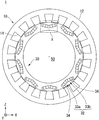
- FIG. 1 is a cross-sectional view illustrating an electric motor in a plane perpendicular to an axis of a rotation shaft of the electric motor.
- FIG. 2 is an enlarged view illustrating a tooth portion in the cross section of the electric motor.
- FIG. 3 is a cross-sectional view for explaining a protrusion portion in details.
- FIG. 4 is a cross-sectional view for explaining a width and another width.
- FIG. 5 is an enlarged view illustrating an area X illustrated in FIG. 1 .
- FIG. 6 is an enlarged view illustrating an area X 1 illustrated in FIG. 5 .
- FIG. 7 is a view for explaining a base point length.
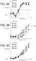
- FIGS. 8A to 8C are graphs illustrating a relationship among an angle, an average torque, and a torque ripple.
- FIG. 9 is a graph illustrating a relationship among a depth of a groove portion, an average torque, and a torque ripple.
- FIGS. 10A and 10B are graphs illustrating a relationship among a length of a groove surface, an average torque, and a torque ripple.
- FIGS. 11A to 11C are graphs illustrating a relationship among an angle formed by a third virtual line and a fourth virtual line, an average torque, and a torque ripple.
- FIGS. 12A and 12B are graphs illustrating a tendency of a torque ripple with respect to an average torque in a case where a ratio between a width and a base point length is changed.
- FIGS. 13A and 13B are graphs illustrating a sixth order component of indoor sounds.
- FIG. 1 is a cross-sectional view illustrating an electric motor 1 in a plane perpendicular to an axis of a rotation shaft 50 of the electric motor (motor) 1 .
- the electric motor 1 is, for example, a permanent magnet-type motor.
- the electric motor 1 is provided on, for example, automobiles such as two-wheeled vehicles, three-wheeled vehicles, and four-wheeled vehicles.
- This automobile is hybrid automobiles and the like (for example, small hybrid automobiles and the like) including an electric motor 1 and, for example, an engine (internal combustion engine) as multiple driving sources for outputting cruising driving force.
- This hybrid automobile runs using the power output by, for example, the electric motor 1 .
- the electric motor 1 has a stator 10 and a rotor 30 .
- the rotor 30 is fixedly connected to the rotation shaft 50 which is an input and output shaft.
- the stator 10 has a cylindrical stator core 12 including multiple tooth portions 14 .
- the stator core 12 (stator core) is formed in an annular shape surrounding the rotor 30 .
- the stator core 12 is provided with the multiple tooth portions 14 projecting radially toward the inside (toward the rotor 30 ) with a regular interval.
- Each tooth portion 14 has a substantially rectangular pillar shape.
- the multiple tooth portions 14 include, for example, the same number of tooth portions corresponding to three phases, i.e., U phase, V phase, and W phase.
- 18 tooth portions 14 are provided.
- the stator 10 generates a rotating magnetic field for rotating the rotor 30 by the current supplied from another device.
- the rotor 30 is arranged inside the stator 10 .
- the rotor 30 rotates in accordance with the rotating magnetic field generated by the stator 10 .
- the rotor 30 is formed in a cylindrical or polygonal columnar shape.
- the rotor 30 is provided with magnet insertion holes 32 with a regular interval in the direction around the axial center.
- the magnet insertion hole 32 includes a pair of a magnet insertion hole piece 33 a and a magnet insertion hole piece 33 b which are divided in a circumferential direction.
- the magnet insertion hole pieces 33 a , 33 b are attached with permanent magnets 34 .
- the outer circumference surfaces of the magnet insertion hole piece 33 a and the magnet insertion hole piece 33 b adjacent to each other in the circumferential direction are substantially in a V shape in the cross section so as to form an angle of less than 180 degrees.
- FIG. 2 is an enlarged view illustrating a tooth portion 14 in the cross section of the electric motor 1 .
- the tooth portion 14 is provided with a protrusion portion 16 for holding a wound coil.
- the protrusion portions 16 protrude to both sides in the circumferential direction of the rotor 30 at the tip portion (at the inside in the radial direction).
- the areas surrounded by the dotted lines in the figure correspond to a protrusion portion 16 R or a protrusion portion 16 L.
- the protrusion portions 16 are integrally made of the same material as the tooth portion 14 .
- FIG. 3 is a cross-sectional view for explaining the protrusion portion 16 in details.
- the protrusion portion 16 includes a first surface L 1 , a second surface L 2 , and a third surface L 3 (a side surface of the protrusion portion).
- the first surface L 1 is a surface extending in the circumferential direction at the tip portion of a base portion 18 of the tooth portion 14 .
- the second surface L 2 is a surface extending in the circumferential direction at a position radially outside of the first surface L 1 .
- the third surface L 3 is a surface connecting the first surface L 1 and the second surface L 2 .
- a line connecting a center P in the circumferential direction of the base portion 18 and a center C of the rotor 30 is defined as a first virtual line IL 1 .
- a line perpendicular to this first virtual line IL 1 is defined as a second virtual line IL 2 .
- An angle ⁇ of the external angle formed by the second virtual line IL 2 and a tangential line TL 1 in contact with the third surface L 3 is 50 degrees or more and less than 90 degrees.
- a ratio B/A which is a ratio of a width B including the tooth portion 14 and the stator protrusion portions 16 with respect to a width A of the base portion 18 of the tooth portion 14 , is within a range from 1.25 to 1.35.
- FIG. 4 is a cross-sectional view for explaining the width A and the width B.
- the width A of the base portion 18 is a width of the base portion 18 of the tooth portion 14 in the circumferential direction.
- the width B is the maximum width including the tooth portion 14 and the two protrusion portions 16 that exist in the circumferential direction of the tooth portion 14 . More specifically, the width B is a length between positions P 1 and P 2 of the intersection lines when the second surface L 2 and the third surface L 3 intersect each other.
- FIG. 5 is an enlarged view illustrating an area X illustrated in FIG. 1 .
- Multiple groove portions 40 recessed in the radial direction of the rotor 30 are formed in an outer circumference wall 36 of the rotor. Where the electric angle of 90 degrees is defined as 100%, the groove portion 40 is set so that an angle ⁇ 1 formed by a third virtual line IL 3 connecting the deepest bottom point 42 of the groove portion and the center C of the rotor 30 and a fourth virtual line IL 4 connecting the magnetic pole center closest to the bottom point 42 and the center of the rotor 30 is an angle from about 30% (27 degrees) to 47% (42.3 degrees).
- an angle of 30% to 47% in the electric angle is equivalent to about 5 to 7 degrees in the mechanical angle. In a case where the poles of the electric motor 1 include eight pairs of poles, an angle of 30% to 47% in the electric angle is equivalent to about 3.75 to 5.25 degrees in the mechanical angle. Where the electric angle of 90 degrees is defined as 100%, the angle ⁇ 1 may be set to an angle from about 30% (27 degrees) to 45% (39.6 degrees).
- FIG. 6 is an enlarged view illustrating an area X 1 illustrated in FIG. 5 .
- the groove portion 40 is formed with two groove surfaces 44 a and 44 b in a circumferential direction with the bottom point 42 being the center.
- Abase point 46 a is provided between the outer circumference wall 36 and the groove surface 44 a
- a base point 46 b is provided between the outer circumference wall 36 and the groove surface 44 b .
- the groove surfaces 44 a and 44 b are not distinguished from each other, the groove surfaces will be referred to as a groove surface 44
- the base points will be referred to as a base point 46 .
- the groove surface 44 is a surface connecting the base point 46 in contact with the outer circumference wall 36 and the bottom point 42 .
- a line virtually connecting the two base points ( 46 a , 46 b ) of the groove portion 40 in contact with the outer circumference wall 36 with the same curvature as the curvature of the outer circumference wall 36 is defined as an outer circumference wall virtual line IL 5 .
- the length from the bottom point 42 to the outer circumference wall virtual line IL 5 is the depth D of the groove portion 40 .
- the depth D is set to a depth between 0.3a and 0.4a. “a” is any given natural number.
- “Width B/base point length” which is the ratio between the length (base point length) obtained by connecting the base point 46 a and the base point 46 b with a straight line and the width B described in FIG. 4 is set to 2.125 or more and 2.55 or less.
- FIG. 7 is a view for explaining a base point length RL.
- the “base point length” is an example of “width C in circumferential direction in V shape”.
- FIGS. 8A to 8C are graphs illustrating a relationship among an angle ⁇ , an average torque, and a torque ripple. Displacement of the torque ripple will be explained in the case where the angle ⁇ between the second virtual line IL 2 and the tangential line TL 1 in contact with the third surface L 3 is set to 90 degrees, 70 degrees, and 50 degrees.
- the horizontal axis indicates the average torque output from the electric motor 1 , and the vertical axis indicates the torque ripple.
- FIG. 8A illustrates a result of the sixth order component (of electrical rotation frequency) with respect to the torque ripple.
- FIG. 8B illustrates a result of the 12-th order component with respect to the torque ripple.
- FIG. 8C illustrates a result of the 18-th order component with respect to the torque ripple.
- the torque ripple of the sixth order component at the angle ⁇ of 50 degrees or 70 degrees is more greatly suppressed than the torque ripple at the angle ⁇ of 90 degrees.
- FIG. 8B when the average torque is a middle level to a larger level (A 2 in FIG. 8B ), the torque ripple of the 12-th order component at the angle ⁇ of 50 degrees or 70 degrees is more greatly suppressed than the torque ripple at the angle ⁇ of 90 degrees.
- FIG. 8C when the average torque is small (A 3 in FIG. 8C ), the torque ripple of the 18-th order component at the angle ⁇ of 50 degrees or 70 degrees is more greatly suppressed than the torque ripple at the angle ⁇ of 90 degrees.
- the torque ripple can be more greatly suppressed than the case where the angle ⁇ is set to 90 degrees or more.
- FIG. 9 is a graph illustrating a relationship among the depth D of the groove portion 40 , the average torque, and the torque ripple.
- the example shown in FIG. 9 illustrates the torque ripple with respect to the average torque in the case where the depth D of the groove portion 40 is set to 3.5 mm, 2 mm, and 1 mm.
- the bottom point 42 of the groove portion 40 is configured to be in the V shape, and the position of the V shape is defined as ⁇ 1 , and the angle is set to a mechanical angle of 6.4 degrees (an electric angle of 38.4 degrees).
- FIG. 9 illustrates a result of the sixth order component with respect to the torque ripple.
- the horizontal axis of FIG. 9 indicates the average torque that is output from the electric motor 1
- the vertical axis of FIG. 9 indicates the torque ripple.
- the torque ripple generated when the depth D is 2 mm or 1 mm is smaller than that generated when the depth D is 3.5 mm.
- the torque ripple of the sixth order component can be suppressed.
- FIGS. 10A and 103 are graphs illustrating a relationship among the length of the groove surface 44 , the average torque, and the torque ripple.
- FIGS. 10A and 10B illustrate the torque ripple with respect to the average torque in the case where the length of the groove surface 44 is set to 6 mm, 8 mm, 10 mm, and 12 mm. The depth of the groove portion 40 is 2 mm, and the other conditions are the same as those of FIG. 9 .
- FIG. 10A illustrates a result of the sixth order component with respect to the torque ripple.
- FIG. 10B illustrates a result of the 18-th component with respect to the torque ripple.
- the torque ripple of the sixth order component generated when the length of the groove surface 44 is set to 8 mm, 10 mm, or 12 mm is more greatly suppressed than the torque ripple generated when the length of the groove surface 44 is set to 6 mm.
- the torque ripple of the 18-th component generated when the length of the groove surface 44 is set to 8 mm, 10 mm, or 12 mm is more greatly suppressed than the torque ripple generated when the length of the groove surface 44 is set to 6 mm.
- the torque ripple can be suppressed by increasing the length of the groove surface 44 .
- the torque ripple of the 18-th component generated when the average torque is small can be suppressed.
- FIGS. 11A to 11C are graphs illustrating a relationship among an angle ⁇ 1 formed by the third virtual line IL 3 and the fourth virtual line IL 4 , the average torque, and the torque ripple.
- the example shown in FIGS. 11A to 11C illustrate the torque ripple with respect to the average torque in the case where the angle ⁇ 1 is set to 6 degrees (36 degrees), 6.4 degrees (38.4 degrees), and 7 degrees (42 degrees).
- the values shown outside of the parentheses indicate the mechanical angles, and the values shown in the parentheses indicate the electric angles.
- the depth of the groove portion 40 is 2 mm, and the other conditions are the same as the conditions of FIG. 9 .
- FIG. 11A illustrates a result of the sixth order component with respect to the torque ripple.
- FIG. 11B illustrates a result of the 12-th order component with respect to the torque ripple.
- FIG. 110 illustrates a result of the 18-th order component with respect to the torque ripple.
- the torque ripple generated when the angle ⁇ 1 is set to 6.4 degrees or 7 degrees is more greatly suppressed than the torque ripple generated when the angle ⁇ 1 is set to 6 degrees.
- the case where the angle ⁇ 1 is set to 7 degrees is more preferable than the case where the angle is set to 6.4 degrees.
- the hybrid vehicle when the hybrid vehicle starts to move from the stopped state by using the power output from the electric motor 1 , the hybrid vehicle is required to suppress the torque ripple of the basic order.
- the angle ⁇ 1 when the angle ⁇ 1 is set to 7 degrees as shown in FIG. 12A , and the average torque is small, the torque ripple of the sixth order component which is the basic order can be suppressed. In this case, the hybrid vehicle becomes a vehicle with excellent vibration and noise characteristics.
- FIGS. 12A and 12B are graphs illustrating a tendency of the torque ripple with respect to the average torque in the case where a ratio between the width B and the base point length RL is changed.
- the example as illustrated in FIGS. 12A and 12B is a result of the sixth order component with respect to the torque ripple.
- the horizontal axis indicates the average torque
- the vertical axis indicates the torque ripple.
- FIG. 12A is a graph illustrating a change in the torque ripple in an area where the average torque is low, i.e., the average torque is zero to a middle level (for example, 30 N/m).
- FIG. 12B is a graph illustrating a change in the torque ripple with respect to the average torque in an area where the average torque is high (for example, 80 to 110 N/m).
- the torque ripple is more greatly suppressed when “width B/base point length RL” is 2.125 or 2.55 than when “width B/base point length RL” is 4.25 in an area where the average torque is low. Further, the torque ripple is more greatly suppressed when “width B/base point length RL” is 2.55 than when “width B/base point length RL” is 2.125. The torque ripple is more greatly suppressed when “width B/base point length RL” is 2.125 or 2.55 than when “width B/base point length RL” is 3.2 or 4.25 in an area where the average torque is high.
- FIGS. 13A and 13B are graphs illustrating a sixth order component of indoor sounds.
- the example as shown in FIGS. 13A and 13B is a result obtained by installing an electric motor in a vehicle and measuring the strength of sound when the vehicle accelerates from stopped state.
- FIG. 13A is a graph illustrating indoor sounds of the electric motor that does not employ the protrusion portion 16 and the groove portion 40 according to the present embodiment.
- FIG. 13B is a graph illustrating indoor sounds of the electric motor 1 that employs the protrusion portion 16 and the groove portion 40 according to the present embodiment.
- the vertical axis indicates a frequency
- the horizontal axis indicates a rotational speed. Sound intensity (decibel) is shown by shading.
- a portion indicated with a thicker shading represents a stronger sound, and a brighter portion indicates a weaker sound.
- An area A 10 in FIG. 13A indicates the level of sound of the 12-th order component.
- An area A 11 in FIG. 13A indicates the level of sound of the sixth order component.
- An area A 12 in FIG. 13B indicates the level of sound of the 12-th order component.
- An area A 13 in FIG. 13B indicates the level of sound of the sixth order component.
- the electric motor 1 according to the present embodiment can suppress the sound level of the sixth order component when the vehicle accelerates from the stopped state.
- an electric motor 1 includes a rotor including a permanent magnet and a stator core formed in an annular shape enclosing the rotor, and including a plurality of tooth portions projecting toward the rotor, wherein on an outer circumference of the rotor, a groove portion recessed in a radial direction of the rotor is formed in a cross section perpendicular to the axial direction of the rotor, an angle formed by a virtual line connecting a bottom point of the groove portion and a center of the rotor and another virtual line connecting a magnetic pole center closest to the bottom point and the center of the rotor is an angle from 30% to 47% or less when an electric angle of 90 degrees is defined as 100%, the tooth portion includes stator protrusion portions protruding to both sides in the circumferential direction of the rotor at a tip portion and holding a wound coil, and a width of the stator protrusion portion in a circumferential direction of the rotor is narrower at an inside
- an electric motor ( 1 ) including: a rotor ( 30 ) including a permanent magnet ( 34 ); and a stator core ( 12 ) formed in an annular shape enclosing the rotor, and including a plurality of tooth portions ( 14 ) projecting toward the rotor, wherein on an outer circumference of the rotor, a groove portion ( 40 ) recessed in a radial direction of the rotor is formed in a cross section perpendicular to the axial direction of the rotor, an angle formed by a virtual line (IL 3 ) connecting a bottom point ( 42 ) of the groove portion and a center (P) of the rotor and another virtual line (IL 4 ) connecting a magnetic pole center closest to the bottom point and the center of the rotor is an angle from 30% to 47% or less when an electric angle of 90 degrees is defined as 100%, the tooth portion includes stator protrusion portions ( 16 ) protruding to both sides in a circumfer
- a depth from an outer circumference surface of the rotor to the bottom point is a depth between 0.3a or more and 0.4a or less.
- an external angle formed by a virtual line perpendicular to a virtual line connecting a center of the tooth portion in the circumferential direction and a center of the rotor and a tangential line in contact with a side surface of the stator protrusion portion is 50 degrees or more and less than 90 degrees.
- a ratio B/A which is a ratio of a width B in the circumferential direction including the tooth portion and the stator protrusion portions with respect to a width A of the tooth portion in the circumferential direction, is within a range from 1.25 or more to 1.35 or less.
- the groove portion is formed in a V shape, and a ratio B/C, which is a ratio of the width B in the circumferential direction including the tooth portion and the stator protrusion portion with respect to a width C of the V shape in the circumferential direction, is within a range from 2.125 or more to 2.55 or less.
- an electric motor capable of effectively suppressing noises can be provided.
Landscapes
- Engineering & Computer Science (AREA)
- Power Engineering (AREA)
- Iron Core Of Rotating Electric Machines (AREA)
- Permanent Field Magnets Of Synchronous Machinery (AREA)
Applications Claiming Priority (2)
| Application Number | Priority Date | Filing Date | Title |
|---|---|---|---|
| JP2016-123901 | 2016-06-22 | ||
| JP2016123901A JP6638135B2 (ja) | 2016-06-22 | 2016-06-22 | 電動機 |
Publications (2)
| Publication Number | Publication Date |
|---|---|
| US20170373550A1 US20170373550A1 (en) | 2017-12-28 |
| US10693330B2 true US10693330B2 (en) | 2020-06-23 |
Family
ID=60677975
Family Applications (1)
| Application Number | Title | Priority Date | Filing Date |
|---|---|---|---|
| US15/627,447 Active 2038-04-30 US10693330B2 (en) | 2016-06-22 | 2017-06-20 | Electric motor |
Country Status (3)
| Country | Link |
|---|---|
| US (1) | US10693330B2 (ja) |
| JP (1) | JP6638135B2 (ja) |
| CN (1) | CN107528398B (ja) |
Cited By (1)
| Publication number | Priority date | Publication date | Assignee | Title |
|---|---|---|---|---|
| WO2022204564A2 (en) | 2021-03-25 | 2022-09-29 | Iovance Biotherapeutics, Inc. | Methods and compositions for t-cell coculture potency assays and use with cell therapy products |
Families Citing this family (6)
| Publication number | Priority date | Publication date | Assignee | Title |
|---|---|---|---|---|
| JP2019161698A (ja) * | 2018-03-07 | 2019-09-19 | 本田技研工業株式会社 | 回転電機のロータ組立体及び回転電機 |
| TWI678864B (zh) * | 2018-07-10 | 2019-12-01 | 愛德利科技股份有限公司 | 永磁電動機 |
| DE102019207471A1 (de) * | 2019-05-22 | 2020-11-26 | Robert Bosch Gmbh | Stator einer elektrischen Maschine |
| US11575285B2 (en) * | 2020-12-09 | 2023-02-07 | Ford Global Technologies, Llc | Electric machine |
| CN112735298B (zh) * | 2021-02-04 | 2022-03-25 | 浙江师范大学 | 一种车轮警示灯 |
| US11916436B2 (en) * | 2021-07-14 | 2024-02-27 | GM Global Technology Operations LLC | Electric machine including a stator having a tooth profile that reduces parasitic voltage |
Citations (8)
| Publication number | Priority date | Publication date | Assignee | Title |
|---|---|---|---|---|
| JP2002171730A (ja) | 2000-12-04 | 2002-06-14 | Hitachi Ltd | 永久磁石式回転電機及びそれを備えた空気調和機 |
| JP2002252947A (ja) | 2001-02-26 | 2002-09-06 | Hitachi Ltd | 回転電機とそれを用いた電動車両 |
| JP2004328956A (ja) | 2003-04-28 | 2004-11-18 | Toyota Motor Corp | 電動機 |
| JP2005151774A (ja) | 2003-11-19 | 2005-06-09 | Sumitomo Heavy Ind Ltd | 永久磁石式同期電動機 |
| JP2005168183A (ja) | 2003-12-03 | 2005-06-23 | Aichi Elec Co | 永久磁石型電動機 |
| JP2008220053A (ja) * | 2007-03-05 | 2008-09-18 | Toyota Motor Corp | 電動機 |
| WO2008153171A1 (ja) * | 2007-06-13 | 2008-12-18 | Toyota Jidosha Kabushiki Kaisha | 回転電機 |
| JP2013099193A (ja) | 2011-11-04 | 2013-05-20 | Suzuki Motor Corp | 電動回転機 |
Family Cites Families (6)
| Publication number | Priority date | Publication date | Assignee | Title |
|---|---|---|---|---|
| JP5278003B2 (ja) * | 2009-01-30 | 2013-09-04 | トヨタ自動車株式会社 | 電動機 |
| JP2013094020A (ja) * | 2011-10-27 | 2013-05-16 | Suzuki Motor Corp | 電動回転機 |
| WO2013098921A1 (ja) * | 2011-12-26 | 2013-07-04 | 三菱電機株式会社 | 永久磁石埋込型モータの回転子ならびにこれを用いた圧縮機、送風機および冷凍空調装置 |
| JP2013162556A (ja) * | 2012-02-01 | 2013-08-19 | Suzuki Motor Corp | 電動回転機 |
| JP2013162557A (ja) * | 2012-02-01 | 2013-08-19 | Suzuki Motor Corp | 電動回転機 |
| JP2014161206A (ja) * | 2013-01-22 | 2014-09-04 | Toyota Industries Corp | 磁石埋込式回転電機 |
-
2016
- 2016-06-22 JP JP2016123901A patent/JP6638135B2/ja active Active
-
2017
- 2017-06-20 US US15/627,447 patent/US10693330B2/en active Active
- 2017-06-22 CN CN201710484119.4A patent/CN107528398B/zh active Active
Patent Citations (8)
| Publication number | Priority date | Publication date | Assignee | Title |
|---|---|---|---|---|
| JP2002171730A (ja) | 2000-12-04 | 2002-06-14 | Hitachi Ltd | 永久磁石式回転電機及びそれを備えた空気調和機 |
| JP2002252947A (ja) | 2001-02-26 | 2002-09-06 | Hitachi Ltd | 回転電機とそれを用いた電動車両 |
| JP2004328956A (ja) | 2003-04-28 | 2004-11-18 | Toyota Motor Corp | 電動機 |
| JP2005151774A (ja) | 2003-11-19 | 2005-06-09 | Sumitomo Heavy Ind Ltd | 永久磁石式同期電動機 |
| JP2005168183A (ja) | 2003-12-03 | 2005-06-23 | Aichi Elec Co | 永久磁石型電動機 |
| JP2008220053A (ja) * | 2007-03-05 | 2008-09-18 | Toyota Motor Corp | 電動機 |
| WO2008153171A1 (ja) * | 2007-06-13 | 2008-12-18 | Toyota Jidosha Kabushiki Kaisha | 回転電機 |
| JP2013099193A (ja) | 2011-11-04 | 2013-05-20 | Suzuki Motor Corp | 電動回転機 |
Non-Patent Citations (1)
| Title |
|---|
| Japanese Office Action for corresponding JP Application No. 2016-123901, dated Dec. 5, 2017. |
Cited By (1)
| Publication number | Priority date | Publication date | Assignee | Title |
|---|---|---|---|---|
| WO2022204564A2 (en) | 2021-03-25 | 2022-09-29 | Iovance Biotherapeutics, Inc. | Methods and compositions for t-cell coculture potency assays and use with cell therapy products |
Also Published As
| Publication number | Publication date |
|---|---|
| CN107528398A (zh) | 2017-12-29 |
| JP6638135B2 (ja) | 2020-01-29 |
| JP2017229159A (ja) | 2017-12-28 |
| US20170373550A1 (en) | 2017-12-28 |
| CN107528398B (zh) | 2019-10-15 |
Similar Documents
| Publication | Publication Date | Title |
|---|---|---|
| US10693330B2 (en) | Electric motor | |
| US11171525B2 (en) | Rotor and permanent magnet electric motor | |
| US9385567B2 (en) | Rotating electric machine | |
| US8847460B2 (en) | Asymmetric stator teeth in an electric motor | |
| US20100013350A1 (en) | Rotor and rotating electric machine with the rotor | |
| JP2006311772A (ja) | 電動機 | |
| US20090134738A1 (en) | Motor and apparatus employing the same | |
| US10432048B2 (en) | Skewed rotor cores with grooves for reducing cogging torque | |
| JP2008099418A (ja) | 永久磁石埋込型電動機 | |
| JP3207654U (ja) | 単相永久磁石モータ | |
| JP5653569B2 (ja) | 回転電動機および内燃機関用過給機 | |
| JP2008312321A (ja) | 回転子および回転電機 | |
| US9559555B2 (en) | Rotor and motor | |
| WO2019017161A1 (ja) | モータ及びブラシレスワイパーモータ | |
| JP5594304B2 (ja) | 回転電機 | |
| US10177613B2 (en) | Rotor and motor | |
| US20170063180A1 (en) | Single Phase Permanent Magnet Motor | |
| WO2021039581A1 (ja) | モータ | |
| JP5947230B2 (ja) | モータ | |
| KR101757542B1 (ko) | 차량용 전기 모터 | |
| JP2013207857A (ja) | ブラシレスモータ | |
| CN212086044U (zh) | 无刷电动机 | |
| US20160126789A1 (en) | Permanent magnet motor | |
| WO2019187752A1 (ja) | 電動モータ | |
| JP7425926B2 (ja) | モーター構造およびモーター製造方法 |
Legal Events
| Date | Code | Title | Description |
|---|---|---|---|
| AS | Assignment |
Owner name: HONDA MOTOR CO., LTD., JAPAN Free format text: ASSIGNMENT OF ASSIGNORS INTEREST;ASSIGNOR:SOMA, SHINGO;REEL/FRAME:042752/0408 Effective date: 20170616 |
|
| STPP | Information on status: patent application and granting procedure in general |
Free format text: DOCKETED NEW CASE - READY FOR EXAMINATION |
|
| STPP | Information on status: patent application and granting procedure in general |
Free format text: NON FINAL ACTION MAILED |
|
| STPP | Information on status: patent application and granting procedure in general |
Free format text: RESPONSE TO NON-FINAL OFFICE ACTION ENTERED AND FORWARDED TO EXAMINER |
|
| STPP | Information on status: patent application and granting procedure in general |
Free format text: FINAL REJECTION MAILED |
|
| STPP | Information on status: patent application and granting procedure in general |
Free format text: NOTICE OF ALLOWANCE MAILED -- APPLICATION RECEIVED IN OFFICE OF PUBLICATIONS |
|
| STPP | Information on status: patent application and granting procedure in general |
Free format text: PUBLICATIONS -- ISSUE FEE PAYMENT VERIFIED |
|
| STCF | Information on status: patent grant |
Free format text: PATENTED CASE |
|
| MAFP | Maintenance fee payment |
Free format text: PAYMENT OF MAINTENANCE FEE, 4TH YEAR, LARGE ENTITY (ORIGINAL EVENT CODE: M1551); ENTITY STATUS OF PATENT OWNER: LARGE ENTITY Year of fee payment: 4 |