US10053264B2 - Bag stacker - Google Patents
Bag stacker Download PDFInfo
- Publication number
- US10053264B2 US10053264B2 US15/093,147 US201615093147A US10053264B2 US 10053264 B2 US10053264 B2 US 10053264B2 US 201615093147 A US201615093147 A US 201615093147A US 10053264 B2 US10053264 B2 US 10053264B2
- Authority
- US
- United States
- Prior art keywords
- bags
- platform
- delivery
- passage
- assembly
- Prior art date
- Legal status (The legal status is an assumption and is not a legal conclusion. Google has not performed a legal analysis and makes no representation as to the accuracy of the status listed.)
- Active
Links
Images


Classifications
-
- B—PERFORMING OPERATIONS; TRANSPORTING
- B65—CONVEYING; PACKING; STORING; HANDLING THIN OR FILAMENTARY MATERIAL
- B65D—CONTAINERS FOR STORAGE OR TRANSPORT OF ARTICLES OR MATERIALS, e.g. BAGS, BARRELS, BOTTLES, BOXES, CANS, CARTONS, CRATES, DRUMS, JARS, TANKS, HOPPERS, FORWARDING CONTAINERS; ACCESSORIES, CLOSURES, OR FITTINGS THEREFOR; PACKAGING ELEMENTS; PACKAGES
- B65D33/00—Details of, or accessories for, sacks or bags
- B65D33/001—Blocks, stacks or like assemblies of bags
-
- B—PERFORMING OPERATIONS; TRANSPORTING
- B65—CONVEYING; PACKING; STORING; HANDLING THIN OR FILAMENTARY MATERIAL
- B65G—TRANSPORT OR STORAGE DEVICES, e.g. CONVEYORS FOR LOADING OR TIPPING, SHOP CONVEYOR SYSTEMS OR PNEUMATIC TUBE CONVEYORS
- B65G57/00—Stacking of articles
- B65G57/02—Stacking of articles by adding to the top of the stack
- B65G57/03—Stacking of articles by adding to the top of the stack from above
- B65G57/035—Stacking of articles by adding to the top of the stack from above with a stepwise downward movement of the stack
-
- B—PERFORMING OPERATIONS; TRANSPORTING
- B65—CONVEYING; PACKING; STORING; HANDLING THIN OR FILAMENTARY MATERIAL
- B65B—MACHINES, APPARATUS OR DEVICES FOR, OR METHODS OF, PACKAGING ARTICLES OR MATERIALS; UNPACKING
- B65B35/00—Supplying, feeding, arranging or orientating articles to be packaged
- B65B35/30—Arranging and feeding articles in groups
- B65B35/50—Stacking one article, or group of articles, upon another before packaging
-
- B—PERFORMING OPERATIONS; TRANSPORTING
- B65—CONVEYING; PACKING; STORING; HANDLING THIN OR FILAMENTARY MATERIAL
- B65G—TRANSPORT OR STORAGE DEVICES, e.g. CONVEYORS FOR LOADING OR TIPPING, SHOP CONVEYOR SYSTEMS OR PNEUMATIC TUBE CONVEYORS
- B65G57/00—Stacking of articles
- B65G57/02—Stacking of articles by adding to the top of the stack
- B65G57/11—Stacking of articles by adding to the top of the stack the articles being stacked by direct action of the feeding conveyor
-
- B—PERFORMING OPERATIONS; TRANSPORTING
- B65—CONVEYING; PACKING; STORING; HANDLING THIN OR FILAMENTARY MATERIAL
- B65B—MACHINES, APPARATUS OR DEVICES FOR, OR METHODS OF, PACKAGING ARTICLES OR MATERIALS; UNPACKING
- B65B5/00—Packaging individual articles in containers or receptacles, e.g. bags, sacks, boxes, cartons, cans, jars
- B65B5/06—Packaging groups of articles, the groups being treated as single articles
- B65B5/061—Filled bags
-
- B—PERFORMING OPERATIONS; TRANSPORTING
- B65—CONVEYING; PACKING; STORING; HANDLING THIN OR FILAMENTARY MATERIAL
- B65G—TRANSPORT OR STORAGE DEVICES, e.g. CONVEYORS FOR LOADING OR TIPPING, SHOP CONVEYOR SYSTEMS OR PNEUMATIC TUBE CONVEYORS
- B65G2201/00—Indexing codes relating to handling devices, e.g. conveyors, characterised by the type of product or load being conveyed or handled
- B65G2201/02—Articles
- B65G2201/0235—Containers
- B65G2201/0238—Bags
Definitions
- the present invention relates to a stacker that receives and stacks articles such as bags, and more particularly but not exclusively to the stacker that inserts the stacks in a container such as a box.
- Articles that are stacked, and subsequently inserted in a container such as a box, are frequently stacked in the box manually.
- bags are produced by packaging machines, with the individual bags then delivered to a conveyor.
- the conveyor delivers the bags to a station at which one or more workers are located.
- the workers gather the bags, arrange them in groups or stacks, and then insert them in a box.
- a first delivery assembly to receive a plurality of the articles at a first receiving position and sequentially move the articles downward along a passage to a first delivery position
- a second delivery assembly to receive the articles from the first delivery assembly, at a second receiving position that is adjacent the first delivery position, so that stacks of the articles are sequentially formed in the passage and supported by the second delivery assembly, with the second delivery assembly moving each stack downward, as each stack is being formed;
- control device coordinating operation of the first and the second delivery assemblies in a manner so that the stacks are formed.
- the second delivery assembly moves each formed stack downward along the passage to a second delivery position.
- the second delivery assembly moves each stack horizontally to a second delivery position.
- the first delivery assembly includes at least one first platform to which the articles are delivered at the first delivery position, the first platform being moved down the passage to the first delivery position, and the second delivery assembly includes at least one second platform, the second platform being movable down the passage from the second receiving position to accommodate transfer of the articles from the first platform to be supported on the second platform to provide for stacking of the article being supported by the second platform.
- the first delivery assembly includes at least one further platform, and the first delivery assembly includes a drive, the drive being operable to move the first platform at a different speed to the further platform.
- each first platform and each second platform includes a plurality of fingers, with adjacent fingers of each platform being separated by a slot, with the fingers of both platforms extending generally transverse relative to said passage when located therein.
- the fingers of each platform are generally parallel.
- the stacking assembly further includes at least one backing member extending adjacent to said passage to aid in retaining the articles on the platforms.
- the stacking assembly further includes two backing members, the backing members being spaced so as to be on opposite sides of the passage, the backing members cooperating to retain the articles on the platform.
- each backing member includes a plurality of upwardly extending slots through which the fingers of the first platform and/or the fingers of the second platform pass.
- both platforms are generally horizontally oriented when passing along said passage, and the platforms when moving along said passage along a generally linear path.
- the stacking assembly further includes a stack transfer member, the stack transfer member being located adjacent the second platform delivery position, and movable to transfer a form stacks from the passage.
- the assembly includes at least one door closing a portion of said passage, the door being movable to an open position to provide for transfer of the stacks from within the passage.
- said door pivots about a generally horizontal axis, and includes a portion that projects into the passage when providing for the delivery of the stacks, the portion being positionable to engage the stacks to ensure that the stacks have a desired height.
- the stacking assembly further includes a conveyor to deliver the articles to the first platform receiving position, the conveyor being angularly movable to provide for the delivery of bags to each first platform so the bags can be arranged in a generally horizontal row, and said control device coordinate operation of the conveyor with the delivery assemblies.
- the delivery assemblies are located on opposite side of the passage.
- each stack is transferred in a predetermined direction to the second delivery position.
- the predetermined direction is downward.
- the predetermined direction is generally horizontal.
- the articles are bags.
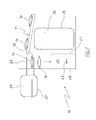
- FIG. 1 is a simplified schematic isometric view of a bag stacking assembly
- FIG. 2 is a schematic isometric view of portion of the assembly of FIG. 1 ;
- FIGS. 3 to 15 are schematic side elevations of the assembly of FIG. 1 , with the assembly at various operational stages.
- FIG. 16 is a schematic side elevation of the assembly of FIG. 1 ;
- FIG. 17 is a further schematic side elevation of the assembly of FIG. 1 ;
- FIG. 18 is a schematic isometric view of the drive assembly employed in assembly of FIG. 1 ;
- FIG. 19 is a schematic side elevation of the drive assembly of FIG. 18 ;
- FIG. 20 is a schematic isometric view of the drive assembly of FIG. 19 ;
- FIG. 21 is a schematic isometric view of a lower portion of the assembly of FIG. 1 ;
- FIG. 22 is a further schematic isometric view of the lower portion as illustrated in FIG. 21 ;
- FIG. 23 is a still further isometric view of the lower portion of FIG. 21 ;
- FIG. 24 is a still further isometric view of the lower portion of FIG. 21 .
- the assembly 10 includes a bag delivery device 11 that in this embodiment is a belt conveyor 12 having an upper belt length 13 that moves the bags 14 in a delivery direction 15 .
- a bag delivery device 11 that in this embodiment is a belt conveyor 12 having an upper belt length 13 that moves the bags 14 in a delivery direction 15 .
- the end 16 of the belt conveyor 12 would be located adjacent a packaging machine that delivers the bags 14 to the surface 13 .
- the bags 14 may be bags of snack foods.
- the belt conveyor 12 has a delivery end 17 from where the bags 14 are delivered to a first delivery assembly 18 (first support).
- the belt conveyor 12 is also movable angularly about a generally upright axis 19 , so that the delivery end 17 moves angularly in the direction 20 .
- the assembly 18 includes a belt or chain drive 21 that supports a plurality of platforms 22 .
- each of the platforms 22 is maintained in a fixed orientation, as each of the platforms 22 moves about a closed loop provided by the drive 21 .
- each of the platforms 22 is provided by a plurality of rods or fingers 23 , which in this embodiment are generally parallel and co-extensive.
- the fingers 23 are transversely spaced so as to be separated by slots 46 , and are fixed to a transverse beam 24 .
- the fingers 23 pass through a backing member 28 provided by a plurality of upwardly oriented wires or rods 25 that are separated by upwardly extending slots 26 .
- the rods 23 pass through the slots 26 , and the rods 25 pass through the slots 46 , when moving about the closed loop provided by the drive 21 .
- the platforms 22 pass in the direction 27 so that adjacent the backing member 28 , the platforms 22 are moving in a downward direction through the slots 26 while projecting therethrough.
- the downward movement is along a linear path.
- the rods 23 (platforms 22 ) are positioned at a receiving position 29 at which the bags 14 are deposited on the platforms 22 in a horizontal row.
- the bags 14 are placed in a horizontal row as a result of the conveyor 12 oscillating in the angular direction 20 so that the bags 14 are sequentially deposited transversely across each platform 22 , as each platform 22 is located at the receiving position 29 .
- the platforms 22 may be moved continuously in the direction 27 , or may be intermittently moved so that the platforms 22 are stationary for at least a portion of time when at the receiving position 29 .
- the backing member 30 is provided by a plurality of wires or rods 31 between which there are slots 32 .
- the bags 14 are formed into stacks 47 between the backing members 28 and 30 . Accordingly between the backing members 28 and 30 there is an upwardly elongated passage 33 within which the bags 14 are stacked.
- the fingers 37 are separated by slots 80 so that the fingers 37 can pass through the slots 32 .
- the platform 22 is moved downwardly so as to move the bags 14 down the passage 33 .
- the bags 14 are stacked in the passage 33 and supported by a second delivery assembly (second support) 34 .
- the assembly 34 is essentially the same construction as the assembly 18 in that it includes a drive 35 having platforms 36 that are moved about a loop provided by the drive 35 .
- the platforms 36 of the drive 35 and the platforms 22 of the drive 18 are moved generally downward through the passage 33 .
- the platforms 36 are preferably maintained in a fixed orientation (horizontal) while passing about the loop provided by the drive 35 .
- the drive 35 includes a chain drive like the chain drive 21 .
- the platforms 36 like the platforms 22 , move along a linear downward path when in the passage 33 .
- the platforms 36 are provided by a plurality of rods or fingers 37 that are fixed to a transverse beam 38 .
- the fingers 37 are transversely spaced so as to be separated by the slots 80 .
- the platform 22 is moved downward along the passage 33 so that the fingers 23 are located adjacent the fingers 37 of a platform 36 .
- the first row of bags 14 are transferred to the platform 36 by movement of the fingers 23 out of the passage 33 .
- the next platform 22 receives a horizontal row of bags 14 and is moved down until it is positioned above the first row of bags 14 supported on the platform 36 , at which time the platform 22 is moved generally horizontally out of the passage 33 so as to deposit the bags 14 supported thereon onto the row of bags 14 below. This process is repeated.
- a stack 47 of bags 14 is formed on the platform 36 by moving the platform 36 downward as the stack 47 is being formed. More particularly each platform 36 is lowered so as to accommodate the next row of bags 14 , that form the stack 47 , to be delivered from the respective platform 22 .
- a completed stack 47 is formed it is moved downward to a second delivery position 75 .
- the movement of the completed stack 47 could be horizontal.
- the stack 47 may have one or more rows of bags 14 .
- the backing member 28 (located at the location 76 ) has an opening 39 that is selectively closed by a pair of doors 40 .
- the doors 40 are open and a transfer member 41 operated to move the stack 47 generally horizontal in the direction 43 to locate the stack 47 in a box 42 at least partly located adjacent the opening 39 .
- a central controller (device) 44 is programmed to coordinate operation of the conveyor 12 , the assembly 18 , the assembly 35 , and movement of the transfer member 41 .
- the assemblies 18 and 34 move the platforms 22 and 36 along a generally linear path down the passage 33 to form the stacks 47 bags 14 .
- the backing member 28 and/or the backing member 30 may be movable horizontally relative to each other to change the horizontal width of the passage 33 to accommodate bags 14 of different sizes.
- side plates 48 may be on either side of the passage 33 to adjust the transverse width of the passage 33 to accommodate a required number of bags 14 in a horizontal row.
- each row may consist of one or more bags 14 , such as two, three, four or five bags 14 .
- the angular movement of the conveyor 11 would need to be adjusted.
- FIGS. 17 to 23 there is provided one embodiment of the assembly 10 .
- the drive 21 includes four pairs of chains 49 , 50 , 51 and 52 .
- the first pair of chains 49 co-operate with the second pair of chains 50 in supporting and moving a first set of the platforms 22 .
- the third pair of chains 51 co-operates with the fourth pair of chains 52 to also support and move a second set of the platforms 22 .
- This enables the platforms 22 (of the first set), driven by the chains 49 and 50 to be operated at different times at different speeds to the platforms 22 (of the second set) supported by the chains 51 and 52 .
- the respective platform 22 may be stationary or moving very slowly. Meanwhile platforms 22 driven by the other pair of chains can be moved at a greater speed so as to be returned to adjacent the position 29 .
- each of the platforms 22 is supported by a pair of arm 54 between which the beam 24 extend so as the fixed thereto.
- Each of the arms 54 has an end supported by a shaft 55 supporting a bearing assembly 56 .
- Each arm 54 is fixed to its respective shaft 55 so that they angularly move in unison.
- Each bearing assembly 56 is supported by a respective chain 49 or 51 .
- each shaft 55 Extending from each shaft 55 is a further arm 57 , with each arm 57 extending to a further bearing assembly 58 , with a further shaft 59 being fixed to a respective one of the arms 57 and supported by a respective bearing assembly 58 .
- Each bearing assembly 58 is supported by a respective one of the chains 50 or 52 .
- the drive 35 is essentially the same construction as the drive 21 , except that the drive 35 is vertically elongated, and the chains move in an opposite angular direction to the direction 27 of the drive 21 .
- the doors 40 include an upper door 61 and a lower door 62 .
- the upper door 61 is pivotably mounted for angular movement about a generally horizontal axis 63
- the lower door 62 is pivotably mounted for angular movement about an axis 64 .
- the axis 63 and 64 are generally parallel and horizontally extending.
- the upper door 61 has a plurality of fingers 65 that are shaped and positioned to pass between the rods 31 .
- the door 61 pivots about the generally horizontal axis 23 from the generally upward position as shown in FIG. 20 , to a generally horizontal position as shown in FIG. 21 , being fingers 25 engage the bags 14 at the upper level of the stack 47 , to ensure that the bags 14 are located at a height that they can be transferred to the box 42 . This may entail some compression of the bags 14 .
- the fingers 23 and 37 are generally horizontally extending when passing downwardly through the passage 33 .
- the fingers 23 and 37 may be inclined, they merely need to be oriented so that the bags 14 can rest thereon.
- the platform 22 and 36 pass downwardly along the passage 33 .
- Their movement may not be linear, it may be curve. All that is required is that the platforms 22 and 36 move downwardly through the passage 33 .
- the bags 14 are deposited on the platform 22 so as to form a horizontal row.
- more than one horizontal row may be supported on each platform 22 .
- the door 61 is formed of two door panels 66 and 67 that are movable relative to each other in the transverse direction 68 to accommodate the stacks 47 being of different widths and boxes 42 having different widths.
- the door 62 is formed of two door panels 69 and 70 .
- the door 69 and 70 are also movable relative to each other in the direction 68 , with the door panels 66 and 67 .
- the panels 66 , 67 , 69 and 70 are mounted on support beams 71 , with the beams 71 being movably mounted on a frame 74 to provide for movement of the panels 66 , 67 , 69 and 70 in the direction 68 .
- each stack 47 may pass.
- side panels 73 are also supported on the beams 71 , with the doors 61 or 62 , and side panels 73 co-operating to provide a generally rectangular aperture through which each stack 47 may pass.
- the door 61 is mounted on the beam 71 for vertical movement to adjust the height of the aperture closed by the doors 61 and 62 .
- the bags 14 are delivered to the receiving position 29 and are arranged in a horizontal row. From there, each row is lowered to a first delivery position 74 that also corresponds to and is adjacent the second receiving position. At the position 74 the bags 14 are transferred to the platforms 36 by the movement of the platforms 22 generally horizontally away from the passage 33 . The platforms 22 return to the position 29 . The platforms 36 are subsequently lowered to accommodate further rows of bags 14 until a stack 47 is formed. Each stack 47 once formed is delivered to the bottom of the passage 33 by the platforms 36 . This is a second delivery position 75 . At this position, each stack 47 is horizontally transferred to a box 42 .
- the platforms 36 are moved horizontally away from the passage 33 and again are transferred back up to the position 74 .
- the stacks 47 once formed and being supported on the platforms 36 , are moved horizontally to a horizontally displaced second delivery position 75 .
Landscapes
- Engineering & Computer Science (AREA)
- Mechanical Engineering (AREA)
- Stacking Of Articles And Auxiliary Devices (AREA)
- Discharge Of Articles From Conveyors (AREA)
- Chain Conveyers (AREA)
- Intermediate Stations On Conveyors (AREA)
- Attitude Control For Articles On Conveyors (AREA)
- Supplying Of Containers To The Packaging Station (AREA)
- Pile Receivers (AREA)
Applications Claiming Priority (2)
| Application Number | Priority Date | Filing Date | Title |
|---|---|---|---|
| AU2015901501A AU2015901501A0 (en) | 2015-04-28 | A bag stacker | |
| AU2015901501 | 2015-04-28 |
Publications (2)
| Publication Number | Publication Date |
|---|---|
| US20160318720A1 US20160318720A1 (en) | 2016-11-03 |
| US10053264B2 true US10053264B2 (en) | 2018-08-21 |
Family
ID=57135789
Family Applications (1)
| Application Number | Title | Priority Date | Filing Date |
|---|---|---|---|
| US15/093,147 Active US10053264B2 (en) | 2015-04-28 | 2016-04-07 | Bag stacker |
Country Status (9)
| Country | Link |
|---|---|
| US (1) | US10053264B2 (ja) |
| JP (1) | JP6688124B2 (ja) |
| AU (2) | AU2016201837B2 (ja) |
| BR (1) | BR102016007584B1 (ja) |
| DE (1) | DE102016207157A1 (ja) |
| ES (1) | ES2588063B1 (ja) |
| GB (1) | GB2540648B (ja) |
| IT (1) | ITUA20161922A1 (ja) |
| MX (1) | MX2016004693A (ja) |
Cited By (1)
| Publication number | Priority date | Publication date | Assignee | Title |
|---|---|---|---|---|
| US20190077604A1 (en) * | 2017-09-14 | 2019-03-14 | Chan Li Machinery Co., Ltd. | Delivery system and layered stacking device for paper packages |
Families Citing this family (13)
| Publication number | Priority date | Publication date | Assignee | Title |
|---|---|---|---|---|
| ITUA20161922A1 (it) | 2015-04-28 | 2017-09-23 | Tna Australia Pty Ltd | Accatastatore di sacchetti. |
| US10809293B2 (en) | 2016-10-27 | 2020-10-20 | Mitsui Chemicals Tochello, Inc. | Method for manufacturing electronic apparatus, adhesive film for manufacturing electronic apparatus, and electronic component testing apparatus |
| CN109014585B (zh) * | 2017-06-12 | 2020-09-11 | 大族激光科技产业集团股份有限公司 | 一种激光打标装置 |
| US10947062B2 (en) * | 2017-08-30 | 2021-03-16 | Pearson Packaging Systems | Product-stacking and case-packing system and method |
| CH714401A1 (de) | 2017-12-04 | 2019-06-14 | Ferag Ag | Vorrichtung zum Beladen und Entladen von schienengeführten Hängefördersystemen. |
| CN108423397B (zh) * | 2018-01-31 | 2019-11-05 | 昆山科默精密机械有限公司 | 一种针对散热片的摆动传送带 |
| CN108382650B (zh) * | 2018-02-13 | 2020-08-11 | 武汉人天包装自动化技术股份有限公司 | 抓取式装袋机 |
| US20200407173A1 (en) * | 2018-04-12 | 2020-12-31 | 888 Brands LLC | Container Transport and Delivery System |
| US11242211B2 (en) | 2018-10-19 | 2022-02-08 | Volm Companies, Inc. | Bin packing system and method |
| CN109335058B (zh) * | 2018-11-20 | 2024-05-03 | 长沙迈迪克智能科技有限公司 | 一种血袋自动装盒设备 |
| DE102020104859A1 (de) * | 2020-02-25 | 2021-08-26 | Khs Gmbh | Palettiervorrichtung sowie Verfahren zur Stapelung von Packstücken |
| KR102386030B1 (ko) * | 2020-06-08 | 2022-04-13 | 주식회사 우도산기 | 면 고속 이송장치 |
| CN114604462B (zh) * | 2022-04-02 | 2024-03-12 | 郑州市顺意科技有限公司 | 一种物料堆叠输送装置 |
Citations (28)
| Publication number | Priority date | Publication date | Assignee | Title |
|---|---|---|---|---|
| US2901952A (en) * | 1955-12-16 | 1959-09-01 | William H Taylor | Apparatus for feeding, counting and stacking magazines, books and other articles |
| US3414138A (en) * | 1965-06-08 | 1968-12-03 | Kochs Adler Ag | Device for the automatic removing and stacking of workpieces, in particular of sewn workpieces |
| US3531905A (en) * | 1967-12-29 | 1970-10-06 | Shozo Omori | Process for forming packaging boxes and simultaneously packing articles therein and apparatus therefor |
| US3729895A (en) * | 1971-07-06 | 1973-05-01 | Touraine Bickfords Foods Inc | Carton loading apparatus |
| US4460169A (en) * | 1981-03-27 | 1984-07-17 | Angelo Bartesaghi | Device for packing sheet-like elements |
| US4465177A (en) * | 1982-02-18 | 1984-08-14 | Dorner Mfg. Corp. | Elevator for a conveying system |
| EP0239742A2 (de) | 1986-03-05 | 1987-10-07 | GRUNDIG E.M.V. Elektro-Mechanische Versuchsanstalt Max Grundig | Verfahren zur Erkennung der Lage von Gegenständen |
| DE3736868A1 (de) | 1987-10-30 | 1989-05-11 | Benz & Hilgers Gmbh | Stapelvorrichtung an verpackungsmaschinen fuer beutel od. dgl. |
| US4934687A (en) * | 1988-01-11 | 1990-06-19 | Galpin Research, Limited Partnership | High speed stream fed stacker method and system for printed products |
| US5022218A (en) * | 1989-03-29 | 1991-06-11 | Bouwe Prakken | Device for filling outers with filled bags |
| GB2245879A (en) | 1990-07-11 | 1992-01-15 | Focke & Co | Apparatus for filling cartons with foil bags |
| US5218813A (en) | 1991-04-24 | 1993-06-15 | Graphic Management Associates, Inc. | Bundling device and method |
| US5383760A (en) * | 1993-11-01 | 1995-01-24 | Ohmstede-Cawley, Ltd. | Apparatus and method for container pattern-forming and palletizing |
| US6145281A (en) * | 1996-05-08 | 2000-11-14 | Dalwell Ab | Method and apparatus for packaging a series of articles in different formations |
| US6641358B2 (en) * | 1999-10-04 | 2003-11-04 | C.G. Bretting Manufacturing Co., Inc. | Web stacker and separator apparatus and method |
| US6925784B2 (en) * | 2003-09-11 | 2005-08-09 | The Procter & Gamble Company | Flexible manufacturing system for consumer packaged products |
| US20060070353A1 (en) | 2004-10-01 | 2006-04-06 | Aaldert Christiaan Van Dam | Device for filling a carton |
| US7699578B2 (en) * | 2005-07-19 | 2010-04-20 | Müller Martini Holding AG | Method and device for forming bundles of stackable objects |
| US20110277423A1 (en) * | 2009-01-27 | 2011-11-17 | A.C.M.I. -Societa' Per Azioni | Palletising device |
| EP2397428A1 (en) | 2010-06-18 | 2011-12-21 | FPS Food Processing Systems B.V. | Apparatus and method for stacking packaging units |
| US20120132091A1 (en) * | 2010-11-30 | 2012-05-31 | Mueller Martini Holding Ag | Apparatus and method for forming bundles composed of printed products |
| US8191702B2 (en) * | 2008-08-26 | 2012-06-05 | Itoh Denki Co., Ltd. | Article lifting device |
| US8240652B2 (en) * | 2004-09-22 | 2012-08-14 | Mtc-Macchine Trasformazione Carta S.R.L. | Method and apparatus for separating packages of interfolded sheets at high flexibility |
| DE102011102245A1 (de) | 2011-05-20 | 2012-11-22 | Hastamat Verpackungstechnik Gmbh | Vorrichtung und Verfahren zum Verpacken von stückigen Produkten |
| US8356967B2 (en) * | 2010-03-15 | 2013-01-22 | Gammtech Corporation | Stacker, stacking system or assembly and method for stacking |
| WO2014195135A1 (de) | 2013-06-07 | 2014-12-11 | Hastamat Verpackungstechnik Gmbh | Verfahren und vorrichtung zur herstellung von verpackungseinheiten in einer schlauchbeutelmaschine |
| WO2015036147A1 (de) | 2013-09-16 | 2015-03-19 | Hastamat Verpackungstechnik Gmbh | Vorrichtung zur herstellung von verpackungseinheiten |
| US20160318720A1 (en) | 2015-04-28 | 2016-11-03 | Tna Australia Pty Limited | Bag stacker |
-
2016
- 2016-03-23 IT ITUA2016A001922A patent/ITUA20161922A1/it unknown
- 2016-03-23 AU AU2016201837A patent/AU2016201837B2/en active Active
- 2016-03-30 JP JP2016067768A patent/JP6688124B2/ja active Active
- 2016-03-31 GB GB1605476.9A patent/GB2540648B/en active Active
- 2016-04-06 BR BR102016007584-0A patent/BR102016007584B1/pt active IP Right Grant
- 2016-04-07 US US15/093,147 patent/US10053264B2/en active Active
- 2016-04-12 MX MX2016004693A patent/MX2016004693A/es unknown
- 2016-04-27 ES ES201630536A patent/ES2588063B1/es active Active
- 2016-04-27 DE DE102016207157.2A patent/DE102016207157A1/de active Pending
-
2020
- 2020-06-26 AU AU2020204283A patent/AU2020204283B2/en active Active
Patent Citations (28)
| Publication number | Priority date | Publication date | Assignee | Title |
|---|---|---|---|---|
| US2901952A (en) * | 1955-12-16 | 1959-09-01 | William H Taylor | Apparatus for feeding, counting and stacking magazines, books and other articles |
| US3414138A (en) * | 1965-06-08 | 1968-12-03 | Kochs Adler Ag | Device for the automatic removing and stacking of workpieces, in particular of sewn workpieces |
| US3531905A (en) * | 1967-12-29 | 1970-10-06 | Shozo Omori | Process for forming packaging boxes and simultaneously packing articles therein and apparatus therefor |
| US3729895A (en) * | 1971-07-06 | 1973-05-01 | Touraine Bickfords Foods Inc | Carton loading apparatus |
| US4460169A (en) * | 1981-03-27 | 1984-07-17 | Angelo Bartesaghi | Device for packing sheet-like elements |
| US4465177A (en) * | 1982-02-18 | 1984-08-14 | Dorner Mfg. Corp. | Elevator for a conveying system |
| EP0239742A2 (de) | 1986-03-05 | 1987-10-07 | GRUNDIG E.M.V. Elektro-Mechanische Versuchsanstalt Max Grundig | Verfahren zur Erkennung der Lage von Gegenständen |
| DE3736868A1 (de) | 1987-10-30 | 1989-05-11 | Benz & Hilgers Gmbh | Stapelvorrichtung an verpackungsmaschinen fuer beutel od. dgl. |
| US4934687A (en) * | 1988-01-11 | 1990-06-19 | Galpin Research, Limited Partnership | High speed stream fed stacker method and system for printed products |
| US5022218A (en) * | 1989-03-29 | 1991-06-11 | Bouwe Prakken | Device for filling outers with filled bags |
| GB2245879A (en) | 1990-07-11 | 1992-01-15 | Focke & Co | Apparatus for filling cartons with foil bags |
| US5218813A (en) | 1991-04-24 | 1993-06-15 | Graphic Management Associates, Inc. | Bundling device and method |
| US5383760A (en) * | 1993-11-01 | 1995-01-24 | Ohmstede-Cawley, Ltd. | Apparatus and method for container pattern-forming and palletizing |
| US6145281A (en) * | 1996-05-08 | 2000-11-14 | Dalwell Ab | Method and apparatus for packaging a series of articles in different formations |
| US6641358B2 (en) * | 1999-10-04 | 2003-11-04 | C.G. Bretting Manufacturing Co., Inc. | Web stacker and separator apparatus and method |
| US6925784B2 (en) * | 2003-09-11 | 2005-08-09 | The Procter & Gamble Company | Flexible manufacturing system for consumer packaged products |
| US8240652B2 (en) * | 2004-09-22 | 2012-08-14 | Mtc-Macchine Trasformazione Carta S.R.L. | Method and apparatus for separating packages of interfolded sheets at high flexibility |
| US20060070353A1 (en) | 2004-10-01 | 2006-04-06 | Aaldert Christiaan Van Dam | Device for filling a carton |
| US7699578B2 (en) * | 2005-07-19 | 2010-04-20 | Müller Martini Holding AG | Method and device for forming bundles of stackable objects |
| US8191702B2 (en) * | 2008-08-26 | 2012-06-05 | Itoh Denki Co., Ltd. | Article lifting device |
| US20110277423A1 (en) * | 2009-01-27 | 2011-11-17 | A.C.M.I. -Societa' Per Azioni | Palletising device |
| US8356967B2 (en) * | 2010-03-15 | 2013-01-22 | Gammtech Corporation | Stacker, stacking system or assembly and method for stacking |
| EP2397428A1 (en) | 2010-06-18 | 2011-12-21 | FPS Food Processing Systems B.V. | Apparatus and method for stacking packaging units |
| US20120132091A1 (en) * | 2010-11-30 | 2012-05-31 | Mueller Martini Holding Ag | Apparatus and method for forming bundles composed of printed products |
| DE102011102245A1 (de) | 2011-05-20 | 2012-11-22 | Hastamat Verpackungstechnik Gmbh | Vorrichtung und Verfahren zum Verpacken von stückigen Produkten |
| WO2014195135A1 (de) | 2013-06-07 | 2014-12-11 | Hastamat Verpackungstechnik Gmbh | Verfahren und vorrichtung zur herstellung von verpackungseinheiten in einer schlauchbeutelmaschine |
| WO2015036147A1 (de) | 2013-09-16 | 2015-03-19 | Hastamat Verpackungstechnik Gmbh | Vorrichtung zur herstellung von verpackungseinheiten |
| US20160318720A1 (en) | 2015-04-28 | 2016-11-03 | Tna Australia Pty Limited | Bag stacker |
Non-Patent Citations (2)
| Title |
|---|
| Search Report dated Feb. 3, 2017 from corresponding Spanish Patent Application No. 201630536 (four pages). |
| Search Report from corresponding British Patent Application GB1605476.9, dated Nov. 17, 2016 (six pages). |
Cited By (2)
| Publication number | Priority date | Publication date | Assignee | Title |
|---|---|---|---|---|
| US20190077604A1 (en) * | 2017-09-14 | 2019-03-14 | Chan Li Machinery Co., Ltd. | Delivery system and layered stacking device for paper packages |
| US10618739B2 (en) * | 2017-09-14 | 2020-04-14 | Chan Li Machinery Co., Ltd. | Delivery system and layered stacking device for paper packages |
Also Published As
| Publication number | Publication date |
|---|---|
| ES2588063A2 (es) | 2016-10-28 |
| ES2588063B1 (es) | 2017-07-20 |
| GB2540648A (en) | 2017-01-25 |
| BR102016007584B1 (pt) | 2023-01-10 |
| BR102016007584A2 (pt) | 2016-11-01 |
| ES2588063R1 (es) | 2017-02-13 |
| JP2016210616A (ja) | 2016-12-15 |
| GB2540648B (en) | 2020-11-04 |
| AU2020204283A1 (en) | 2020-07-16 |
| AU2016201837B2 (en) | 2020-07-23 |
| AU2016201837A1 (en) | 2016-11-17 |
| AU2020204283B2 (en) | 2021-07-22 |
| MX2016004693A (es) | 2018-03-01 |
| ITUA20161922A1 (it) | 2017-09-23 |
| JP6688124B2 (ja) | 2020-04-28 |
| US20160318720A1 (en) | 2016-11-03 |
| DE102016207157A1 (de) | 2016-11-03 |
Similar Documents
| Publication | Publication Date | Title |
|---|---|---|
| AU2020204283B2 (en) | A bag stacker | |
| JP2016210616A5 (ja) | ||
| US10442638B2 (en) | Method and apparatus for conveying articles, piece goods and/or bundles within at least two conveying path sections | |
| CN106742426B (zh) | 多用型盒装物品自动装箱设备 | |
| US11613387B2 (en) | Vibrating device for the orderly rearrangement of folding boxes in a container, discharging conveyor and method for discharging containers | |
| CN110431095B (zh) | 用于从多个产品生产产品的批次的装置 | |
| JP5578611B2 (ja) | 物品の箱詰め装置及び方法 | |
| US8215087B2 (en) | Apparatus and method of forming a stack of food products within a storage container | |
| US11021328B2 (en) | Packaging machine with transport chain | |
| EP2947018B1 (en) | System for filling an open top box with packages | |
| US7464804B2 (en) | Automatic pallet loader system and method | |
| KR101125154B1 (ko) | 단위지함 정렬 장치 | |
| CN206375423U (zh) | 用于水平地移动物品组的设备 | |
| US6952911B2 (en) | Automatic case packaging system | |
| JP7401060B2 (ja) | 搬送装置及び搬送方法 | |
| US20060263193A1 (en) | Device for stacking flat products | |
| US20130206544A1 (en) | Apparatus And Method For Placing Rows And/Or Piles Of Packaged Units Onto Transport Pallets | |
| JP7369491B2 (ja) | 取出機構、取出・搬送システム及び取出・移動・搬送システム | |
| CN204642243U (zh) | 铁钉自动包装机 | |
| US11577862B2 (en) | Automatic case packing equipment for stand-up pouches | |
| JP7293751B2 (ja) | 搬送装置 | |
| JP2022050216A (ja) | 物品集積装置 | |
| JP3453419B2 (ja) | 長物野菜の箱詰装置 | |
| US20170233119A1 (en) | Quad Wicket Exchange System | |
| JPH04339703A (ja) | 箱詰装置 |
Legal Events
| Date | Code | Title | Description |
|---|---|---|---|
| AS | Assignment |
Owner name: TNA AUSTRALIA PTY LIMITED, AUSTRALIA Free format text: ASSIGNMENT OF ASSIGNORS INTEREST;ASSIGNORS:ROOS, LAWRENCE;PEARSON, BRIAN;REEL/FRAME:038608/0380 Effective date: 20160503 |
|
| STCF | Information on status: patent grant |
Free format text: PATENTED CASE |
|
| MAFP | Maintenance fee payment |
Free format text: PAYMENT OF MAINTENANCE FEE, 4TH YEAR, LARGE ENTITY (ORIGINAL EVENT CODE: M1551); ENTITY STATUS OF PATENT OWNER: LARGE ENTITY Year of fee payment: 4 |