US10041292B2 - Low-power radio-frequency receiver - Google Patents
Low-power radio-frequency receiver Download PDFInfo
- Publication number
- US10041292B2 US10041292B2 US13/415,537 US201213415537A US10041292B2 US 10041292 B2 US10041292 B2 US 10041292B2 US 201213415537 A US201213415537 A US 201213415537A US 10041292 B2 US10041292 B2 US 10041292B2
- Authority
- US
- United States
- Prior art keywords
- receiver
- operable
- packet
- wireless
- controller
- Prior art date
- Legal status (The legal status is an assumption and is not a legal conclusion. Google has not performed a legal analysis and makes no representation as to the accuracy of the status listed.)
- Active, expires
Links
Images


Classifications
-
- H—ELECTRICITY
- H04—ELECTRIC COMMUNICATION TECHNIQUE
- H04W—WIRELESS COMMUNICATION NETWORKS
- H04W52/00—Power management, e.g. TPC [Transmission Power Control], power saving or power classes
- H04W52/02—Power saving arrangements
- H04W52/0209—Power saving arrangements in terminal devices
- H04W52/0225—Power saving arrangements in terminal devices using monitoring of external events, e.g. the presence of a signal
- H04W52/0238—Power saving arrangements in terminal devices using monitoring of external events, e.g. the presence of a signal where the received signal is an unwanted signal, e.g. interference or idle signal
-
- E—FIXED CONSTRUCTIONS
- E06—DOORS, WINDOWS, SHUTTERS, OR ROLLER BLINDS IN GENERAL; LADDERS
- E06B—FIXED OR MOVABLE CLOSURES FOR OPENINGS IN BUILDINGS, VEHICLES, FENCES OR LIKE ENCLOSURES IN GENERAL, e.g. DOORS, WINDOWS, BLINDS, GATES
- E06B9/00—Screening or protective devices for wall or similar openings, with or without operating or securing mechanisms; Closures of similar construction
- E06B9/24—Screens or other constructions affording protection against light, especially against sunshine; Similar screens for privacy or appearance; Slat blinds
- E06B9/26—Lamellar or like blinds, e.g. venetian blinds
- E06B9/38—Other details
-
- E—FIXED CONSTRUCTIONS
- E06—DOORS, WINDOWS, SHUTTERS, OR ROLLER BLINDS IN GENERAL; LADDERS
- E06B—FIXED OR MOVABLE CLOSURES FOR OPENINGS IN BUILDINGS, VEHICLES, FENCES OR LIKE ENCLOSURES IN GENERAL, e.g. DOORS, WINDOWS, BLINDS, GATES
- E06B9/00—Screening or protective devices for wall or similar openings, with or without operating or securing mechanisms; Closures of similar construction
- E06B9/24—Screens or other constructions affording protection against light, especially against sunshine; Similar screens for privacy or appearance; Slat blinds
- E06B9/26—Lamellar or like blinds, e.g. venetian blinds
- E06B9/28—Lamellar or like blinds, e.g. venetian blinds with horizontal lamellae, e.g. non-liftable
- E06B9/30—Lamellar or like blinds, e.g. venetian blinds with horizontal lamellae, e.g. non-liftable liftable
- E06B9/32—Operating, guiding, or securing devices therefor
- E06B9/322—Details of operating devices, e.g. pulleys, brakes, spring drums, drives
-
- E—FIXED CONSTRUCTIONS
- E06—DOORS, WINDOWS, SHUTTERS, OR ROLLER BLINDS IN GENERAL; LADDERS
- E06B—FIXED OR MOVABLE CLOSURES FOR OPENINGS IN BUILDINGS, VEHICLES, FENCES OR LIKE ENCLOSURES IN GENERAL, e.g. DOORS, WINDOWS, BLINDS, GATES
- E06B9/00—Screening or protective devices for wall or similar openings, with or without operating or securing mechanisms; Closures of similar construction
- E06B9/56—Operating, guiding or securing devices or arrangements for roll-type closures; Spring drums; Tape drums; Counterweighting arrangements therefor
- E06B9/68—Operating devices or mechanisms, e.g. with electric drive
- E06B9/70—Operating devices or mechanisms, e.g. with electric drive comprising an electric motor positioned outside the roller
-
- E—FIXED CONSTRUCTIONS
- E06—DOORS, WINDOWS, SHUTTERS, OR ROLLER BLINDS IN GENERAL; LADDERS
- E06B—FIXED OR MOVABLE CLOSURES FOR OPENINGS IN BUILDINGS, VEHICLES, FENCES OR LIKE ENCLOSURES IN GENERAL, e.g. DOORS, WINDOWS, BLINDS, GATES
- E06B9/00—Screening or protective devices for wall or similar openings, with or without operating or securing mechanisms; Closures of similar construction
- E06B9/56—Operating, guiding or securing devices or arrangements for roll-type closures; Spring drums; Tape drums; Counterweighting arrangements therefor
- E06B9/68—Operating devices or mechanisms, e.g. with electric drive
- E06B9/72—Operating devices or mechanisms, e.g. with electric drive comprising an electric motor positioned inside the roller
-
- H—ELECTRICITY
- H04—ELECTRIC COMMUNICATION TECHNIQUE
- H04W—WIRELESS COMMUNICATION NETWORKS
- H04W52/00—Power management, e.g. TPC [Transmission Power Control], power saving or power classes
- H04W52/02—Power saving arrangements
- H04W52/0209—Power saving arrangements in terminal devices
- H04W52/0212—Power saving arrangements in terminal devices managed by the network, e.g. network or access point is master and terminal is slave
- H04W52/0216—Power saving arrangements in terminal devices managed by the network, e.g. network or access point is master and terminal is slave using a pre-established activity schedule, e.g. traffic indication frame
-
- H—ELECTRICITY
- H04—ELECTRIC COMMUNICATION TECHNIQUE
- H04W—WIRELESS COMMUNICATION NETWORKS
- H04W52/00—Power management, e.g. TPC [Transmission Power Control], power saving or power classes
- H04W52/02—Power saving arrangements
- H04W52/0209—Power saving arrangements in terminal devices
- H04W52/0212—Power saving arrangements in terminal devices managed by the network, e.g. network or access point is master and terminal is slave
- H04W52/0219—Power saving arrangements in terminal devices managed by the network, e.g. network or access point is master and terminal is slave where the power saving management affects multiple terminals
-
- H—ELECTRICITY
- H04—ELECTRIC COMMUNICATION TECHNIQUE
- H04W—WIRELESS COMMUNICATION NETWORKS
- H04W52/00—Power management, e.g. TPC [Transmission Power Control], power saving or power classes
- H04W52/02—Power saving arrangements
- H04W52/0209—Power saving arrangements in terminal devices
- H04W52/0225—Power saving arrangements in terminal devices using monitoring of external events, e.g. the presence of a signal
- H04W52/0229—Power saving arrangements in terminal devices using monitoring of external events, e.g. the presence of a signal where the received signal is a wanted signal
-
- H—ELECTRICITY
- H04—ELECTRIC COMMUNICATION TECHNIQUE
- H04W—WIRELESS COMMUNICATION NETWORKS
- H04W52/00—Power management, e.g. TPC [Transmission Power Control], power saving or power classes
- H04W52/02—Power saving arrangements
- H04W52/0209—Power saving arrangements in terminal devices
- H04W52/0225—Power saving arrangements in terminal devices using monitoring of external events, e.g. the presence of a signal
- H04W52/0235—Power saving arrangements in terminal devices using monitoring of external events, e.g. the presence of a signal where the received signal is a power saving command
-
- H—ELECTRICITY
- H04—ELECTRIC COMMUNICATION TECHNIQUE
- H04W—WIRELESS COMMUNICATION NETWORKS
- H04W52/00—Power management, e.g. TPC [Transmission Power Control], power saving or power classes
- H04W52/02—Power saving arrangements
- H04W52/0209—Power saving arrangements in terminal devices
- H04W52/0225—Power saving arrangements in terminal devices using monitoring of external events, e.g. the presence of a signal
- H04W52/0245—Power saving arrangements in terminal devices using monitoring of external events, e.g. the presence of a signal according to signal strength
-
- H—ELECTRICITY
- H04—ELECTRIC COMMUNICATION TECHNIQUE
- H04W—WIRELESS COMMUNICATION NETWORKS
- H04W52/00—Power management, e.g. TPC [Transmission Power Control], power saving or power classes
- H04W52/02—Power saving arrangements
- H04W52/0209—Power saving arrangements in terminal devices
- H04W52/0261—Power saving arrangements in terminal devices managing power supply demand, e.g. depending on battery level
- H04W52/0274—Power saving arrangements in terminal devices managing power supply demand, e.g. depending on battery level by switching on or off the equipment or parts thereof
- H04W52/028—Power saving arrangements in terminal devices managing power supply demand, e.g. depending on battery level by switching on or off the equipment or parts thereof switching on or off only a part of the equipment circuit blocks
-
- E—FIXED CONSTRUCTIONS
- E06—DOORS, WINDOWS, SHUTTERS, OR ROLLER BLINDS IN GENERAL; LADDERS
- E06B—FIXED OR MOVABLE CLOSURES FOR OPENINGS IN BUILDINGS, VEHICLES, FENCES OR LIKE ENCLOSURES IN GENERAL, e.g. DOORS, WINDOWS, BLINDS, GATES
- E06B9/00—Screening or protective devices for wall or similar openings, with or without operating or securing mechanisms; Closures of similar construction
- E06B9/24—Screens or other constructions affording protection against light, especially against sunshine; Similar screens for privacy or appearance; Slat blinds
- E06B9/26—Lamellar or like blinds, e.g. venetian blinds
- E06B9/262—Lamellar or like blinds, e.g. venetian blinds with flexibly-interconnected horizontal or vertical strips; Concertina blinds, i.e. upwardly folding flexible screens
- E06B2009/2625—Pleated screens, e.g. concertina- or accordion-like
-
- E—FIXED CONSTRUCTIONS
- E06—DOORS, WINDOWS, SHUTTERS, OR ROLLER BLINDS IN GENERAL; LADDERS
- E06B—FIXED OR MOVABLE CLOSURES FOR OPENINGS IN BUILDINGS, VEHICLES, FENCES OR LIKE ENCLOSURES IN GENERAL, e.g. DOORS, WINDOWS, BLINDS, GATES
- E06B9/00—Screening or protective devices for wall or similar openings, with or without operating or securing mechanisms; Closures of similar construction
- E06B9/56—Operating, guiding or securing devices or arrangements for roll-type closures; Spring drums; Tape drums; Counterweighting arrangements therefor
- E06B9/68—Operating devices or mechanisms, e.g. with electric drive
- E06B2009/6809—Control
- E06B2009/6818—Control using sensors
-
- E—FIXED CONSTRUCTIONS
- E06—DOORS, WINDOWS, SHUTTERS, OR ROLLER BLINDS IN GENERAL; LADDERS
- E06B—FIXED OR MOVABLE CLOSURES FOR OPENINGS IN BUILDINGS, VEHICLES, FENCES OR LIKE ENCLOSURES IN GENERAL, e.g. DOORS, WINDOWS, BLINDS, GATES
- E06B9/00—Screening or protective devices for wall or similar openings, with or without operating or securing mechanisms; Closures of similar construction
- E06B9/56—Operating, guiding or securing devices or arrangements for roll-type closures; Spring drums; Tape drums; Counterweighting arrangements therefor
- E06B9/68—Operating devices or mechanisms, e.g. with electric drive
- E06B2009/6809—Control
- E06B2009/6872—Control using counters to determine shutter position
-
- E—FIXED CONSTRUCTIONS
- E06—DOORS, WINDOWS, SHUTTERS, OR ROLLER BLINDS IN GENERAL; LADDERS
- E06B—FIXED OR MOVABLE CLOSURES FOR OPENINGS IN BUILDINGS, VEHICLES, FENCES OR LIKE ENCLOSURES IN GENERAL, e.g. DOORS, WINDOWS, BLINDS, GATES
- E06B9/00—Screening or protective devices for wall or similar openings, with or without operating or securing mechanisms; Closures of similar construction
- E06B9/56—Operating, guiding or securing devices or arrangements for roll-type closures; Spring drums; Tape drums; Counterweighting arrangements therefor
- E06B9/62—Counterweighting arrangements
-
- H—ELECTRICITY
- H04—ELECTRIC COMMUNICATION TECHNIQUE
- H04W—WIRELESS COMMUNICATION NETWORKS
- H04W52/00—Power management, e.g. TPC [Transmission Power Control], power saving or power classes
- H04W52/02—Power saving arrangements
- H04W52/0209—Power saving arrangements in terminal devices
- H04W52/0261—Power saving arrangements in terminal devices managing power supply demand, e.g. depending on battery level
- H04W52/0287—Power saving arrangements in terminal devices managing power supply demand, e.g. depending on battery level changing the clock frequency of a controller in the equipment
-
- Y—GENERAL TAGGING OF NEW TECHNOLOGICAL DEVELOPMENTS; GENERAL TAGGING OF CROSS-SECTIONAL TECHNOLOGIES SPANNING OVER SEVERAL SECTIONS OF THE IPC; TECHNICAL SUBJECTS COVERED BY FORMER USPC CROSS-REFERENCE ART COLLECTIONS [XRACs] AND DIGESTS
- Y02—TECHNOLOGIES OR APPLICATIONS FOR MITIGATION OR ADAPTATION AGAINST CLIMATE CHANGE
- Y02A—TECHNOLOGIES FOR ADAPTATION TO CLIMATE CHANGE
- Y02A30/00—Adapting or protecting infrastructure or their operation
- Y02A30/24—Structural elements or technologies for improving thermal insulation
-
- Y02A30/257—
-
- Y—GENERAL TAGGING OF NEW TECHNOLOGICAL DEVELOPMENTS; GENERAL TAGGING OF CROSS-SECTIONAL TECHNOLOGIES SPANNING OVER SEVERAL SECTIONS OF THE IPC; TECHNICAL SUBJECTS COVERED BY FORMER USPC CROSS-REFERENCE ART COLLECTIONS [XRACs] AND DIGESTS
- Y02—TECHNOLOGIES OR APPLICATIONS FOR MITIGATION OR ADAPTATION AGAINST CLIMATE CHANGE
- Y02B—CLIMATE CHANGE MITIGATION TECHNOLOGIES RELATED TO BUILDINGS, e.g. HOUSING, HOUSE APPLIANCES OR RELATED END-USER APPLICATIONS
- Y02B80/00—Architectural or constructional elements improving the thermal performance of buildings
-
- Y02B80/50—
-
- Y—GENERAL TAGGING OF NEW TECHNOLOGICAL DEVELOPMENTS; GENERAL TAGGING OF CROSS-SECTIONAL TECHNOLOGIES SPANNING OVER SEVERAL SECTIONS OF THE IPC; TECHNICAL SUBJECTS COVERED BY FORMER USPC CROSS-REFERENCE ART COLLECTIONS [XRACs] AND DIGESTS
- Y02—TECHNOLOGIES OR APPLICATIONS FOR MITIGATION OR ADAPTATION AGAINST CLIMATE CHANGE
- Y02D—CLIMATE CHANGE MITIGATION TECHNOLOGIES IN INFORMATION AND COMMUNICATION TECHNOLOGIES [ICT], I.E. INFORMATION AND COMMUNICATION TECHNOLOGIES AIMING AT THE REDUCTION OF THEIR OWN ENERGY USE
- Y02D30/00—Reducing energy consumption in communication networks
- Y02D30/70—Reducing energy consumption in communication networks in wireless communication networks
-
- Y02D70/00—
-
- Y02D70/12—
-
- Y02D70/122—
Definitions
- the present invention relates to a radio-frequency (RF) load control system, and more specifically, to a low-power RF receiver for use in RF control devices, such as, a battery-powered motorized window treatment or a two-wire dimmer switch.
- RF radio-frequency
- Control systems for controlling electrical loads are known. Such control systems often use the transmission of radio-frequency (RF) signals to provide wireless communication between the control devices of the system.
- the prior art lighting control systems include wireless remote controls, such as, table-top and wall-mounted master controls (e.g., keypads) and car visor controls.
- the master controls of the prior art lighting control system each include a plurality of buttons and transmit RF signals to load control devices (such as dimmer switches) to control the intensities of controlled lighting loads.
- the master controls may also each include one or more visual indicators, e.g., light-emitting diodes (LEDs), for providing feedback to users of the lighting control system.
- LEDs light-emitting diodes
- the car visor controls are able to be clipped to the visor of an automobile and include one or more buttons for controlling the lighting loads of the lighting control system.
- An example of a prior art RF lighting control system is disclosed in commonly-assigned U.S. Pat. No. 5,905,442, issued on May 18, 1999, entitled METHOD AND APPARATUS FOR CONTROLLING AND DETERMINING THE STATUS OF ELECTRICAL DEVICES FROM REMOTE LOCATIONS, the entire disclosure of which is hereby incorporated by reference.
- the RF circuitry i.e., the transmitters, receivers, or transceivers
- the RF circuitry is one of the primary consumers of battery power in the devices. Therefore, typical prior art battery-powered wireless control devices have attempted to limit the amount of time that the control devices are actively transmitting RF signals.
- the RF circuitry is put into a sleep mode in which these circuits drawn less current from the batteries. The RF circuitry is periodically woken up to determine if any RF signals are being received. Thus, the amount of time that the RF circuits are awake as compared to the amount of time that the RF circuits are asleep affects the amount of current drawn from the batteries as well as the lifetime of the batteries.
- U.S. Pat. No. 7,869,481, issued Dec. 28, 2010, entitled LOW POWER RF CONTROL SYSTEM describes a motorized window treatment having an RF receiver, for allowing the motorized window treatment to be controlled from a handheld RF remote control.
- the remote control transmits command signals that each include a pre-sync pulse time and subsequent message data.
- the RF receiver of the motorized window treatment periodically wakes up for a short period of time at a rate that ensures that the RF receiver checks for RF signals at least two times during the amount of time required to transmit the pre-sync pulse time of each control signal.
- the RF receiver wakes up at least two times each 30 milliseconds.
- the amount of time that the RF circuitry is awake as compared to being in the sleep mode is dependent upon a characteristic of the command signals, i.e., the length of the pre-sync pulse time, and must be shorter than the pre-sync pulse time. Therefore, the sleep time cannot be increased (to thus decrease the power consumption of the RF receiver) without increasing the pre-sync pulse time, which will decrease the throughput of the system.
- the length of the command signals may be limited by national or regional standards.
- a low-power RF receiver that may be used in battery-powered control devices to lead to longer battery lifetimes.
- a low-power RF receiver that is able to check for RF signals at a rate that is not limited by a characteristic of each of the transmitted RF signals.
- the present invention provides a low-power radio-frequency (RF) receiver that is characterized by a decreased current consumption over prior art RF receivers.
- the low-power RF receiver may be used in, for example, a battery-powered control device, such as a motorized window treatment that controls the position of a covering material that is adapted to hang in front of an opening, such as a window.
- a battery-powered control device such as a motorized window treatment that controls the position of a covering material that is adapted to hang in front of an opening, such as a window.
- the battery-powered motorized window treatment has a much longer (and more practical) lifetime than typical prior art battery-powered motorized window treatments (e.g., approximately three years).
- the low-power RF receiver is operable to receive RF signals from various types of RF transmitters, such as, for example, battery-powered remote controls, occupancy sensors, vacancy sensors, daylight sensors, temperature sensors, humidity sensors, security sensors, proximity sensors, keypads, key fobs, cell phones, smart phones, tablets, personal digital assistants, personal computers, timeclocks, audio-visual controls, safety devices, central control transmitters, or any combination of these input devices.
- RF transmitters such as, for example, battery-powered remote controls, occupancy sensors, vacancy sensors, daylight sensors, temperature sensors, humidity sensors, security sensors, proximity sensors, keypads, key fobs, cell phones, smart phones, tablets, personal digital assistants, personal computers, timeclocks, audio-visual controls, safety devices, central control transmitters, or any combination of these input devices.
- the low-power RF receiver is used in a load control system having an RF transmitter that transmits a number of sequential packets via RF signals with each packets including the same command and having a packet length.
- the low-power RF receiver is operable to use an RF sub-sampling technique to check for the RF signals and then put the RF receiver to sleep for a sleep time that is longer than the packet length of the packets to thus conserve battery power and lengthen the lifetime of the batteries.
- the low-power RF receiver compares detected RF energy to a detect threshold that may be increased to decrease the sensitivity of the low-power RF receiver and increase the lifetime of the batteries.
- the low-power RF receiver After detecting that an RF signal is being transmitted, the low-power RF receiver is put to sleep for a snooze time period that is longer than the sleep time and just slightly shorter than the time between two consecutive transmitted packets to further conserve battery power.
- the low-power RF receiver may be responsive to RF signals transmitted at a different frequency than the frequency to which other control devices of the load control system are responsive to limit the amount of time that the RF receiver wakes up to process incoming RF signals and thus conserve battery power.
- the RF transmitter is adapted to transmit a number of sequential digital messages at a predetermined transmission rate, where each of the digital messages including the same command and characterized by a packet length.
- the load control device comprises an RF receiver adapted to receive at least one of the sequential digital messages, and a controller operatively coupled to the RF transceiver for receiving the at least one of the sequential digital messages and controlling the load in response to the received digital message.
- the RF receiver is enabled for a sample time period to determine if the RF transmitter is transmitting one of the digital messages.
- the RF receiver enters a sleep mode for a sleep time period between consecutive sample time periods. The sleep time period of the RF receiver is longer than the packet length of each of the digital messages.
- an RF communication system comprises an RF transmitter adapted to transmit a number of sequential digital messages at a predetermined transmission rate, and an RF receiver adapted to receive at least one of the sequential digital messages.
- Each of the digital messages including the same command and characterized by a packet length.
- the RF receiver is enabled for a sampling time to determine if the RF transmitter is transmitting one of the digital messages, and enters a sleep mode for a sleep time period between consecutive sample time periods. The sleep time period of the RF receiver is longer than the packet length of each of the digital messages.
- a wireless signal receiver comprises a wireless receiver circuit for detecting transmitted signals transmitted in a predetermined number of packets, where each packet comprises the same data, there being a packet time and a time between packets substantially longer than the packet time.
- the wireless signal receiver also comprises a control circuit for turning on the wireless receiver circuit for an on-time, where the on-time is substantially less than an off-time of the wireless receiver circuit.
- the on-time of the wireless receiver circuit is also substantially less than the packet time and the off-time between on-times being less than the time between packets. The off-time is selected so that within the plurality of packets, the on-time will coincide with the packet time to ensure that the wireless receiver circuit detects at least one packet during the transmission of the predetermined number of packets if packets are being transmitted.
- a method of communicating digital messages in a load control system comprises: (1) transmitting a number of sequential digital messages at a predetermined transmission rate, each of the digital messages including the same command and characterized by a packet length; (2) enabling an RF receiver for a sample time period to determine if the RF transmitter is transmitting one of the digital messages; and (3) putting the RF receiver in a sleep mode for a sleep time period between consecutive sample time periods.
- the sleep time period of the RF receiver is longer than the packet length of each of the digital messages.
- a wireless signal receiver circuit for detecting wireless control signals has an on/off operation to conserve power.
- the wireless signal receiver circuit comprises a control circuit, and a wireless receiver having an on state when it consumes power and an off state when it consumes less power than consumed in the on state.
- the on state has a duration substantially shorter than the off state, whereby the wireless receiver receives wireless control signals during the on state to be processed by the control circuit.
- the wireless control signals are sent in packets with a packet time such that there is a predefined time between packets.
- the wireless receiver is operable to periodically be in the on state for a sample time substantially less than the packet time to detect a wireless control signal, whereby upon detecting a first packet during the sample time, the wireless receiver is operable to enter the off state to conserve power for an amount of time slightly less than the predefined time between packets, to subsequently turn on and remain on until a succeeding packet starts to be received, and to turn off after the succeeding packet is fully received.
- a battery-powered wireless device comprises: a control circuit having an on state when it consumes power and an off state when it consumes less power than consumed in the on state, and a wireless receiver circuit operable to periodically check for wireless signals.
- the wireless receiver circuit has a detect threshold wherein the wireless receiver circuit is operable to determine whether a wireless signal exceeds the detect threshold.
- the receiver circuit is operable to cause the control circuit to be in on state in response to determining that a wireless signal exceeds the detect threshold.
- the control circuit is further operable to adjust the detect threshold of the wireless receiver circuit whereby the detect threshold can be increased to prevent noise signals from causing the wireless receiver circuit to turn on the control circuit thereby conserving battery power.
- a system for conserving battery power of a battery powered wireless signal receiver comprises a wireless signal receiver that periodically turns on to determine if a wireless signal is being transmitted and is capable of receiving on any of multiple channels.
- the wireless signal receiver includes a control circuit that determines if the wireless signal is intended for the wireless signal receiver.
- the transceiver circuit retransmits the wireless signals and determines a number of transmitted wireless signals. If the number exceeds a threshold amount, the transceiver circuit communicates with the wireless signal receiver to change the channel of communication to an alternate channel and retransmits wireless signals intended for the wireless signal receiver on the alternate channel, whereby the wireless signal receiver will receive fewer wireless signals on the alternate channel, thereby remaining on for less time and reducing battery power consumption.
- a wireless control system comprises: (1) a first wireless signal receiver capable of receiving on wireless signals on a first channel; (2) a second wireless signal receiver that periodically turns on to determine if wireless signals are being transmitted, the second wireless signal receiver being capable of receiving on wireless signals on a second channel; and (3) a transceiver circuit for retransmitting said wireless signals, said transceiver circuit operable to receive a first wireless signal on the first channel and to determine that the first wireless signal contains control information intended for the second wireless signal receiver.
- the transceiver circuit is operable to change its channel of communication from the first channel to the second channel, and transmit the control information in a second wireless signal to the second wireless signal receiver on the second channel.
- FIG. 1 is a perspective view of a motorized window treatment system having a battery-powered motorized window treatment and a remote control according to a first embodiment of the present invention
- FIG. 2 is a perspective view of the battery-powered motorized window treatment of FIG. 1 in a full-closed position
- FIG. 3 is a right side view of the battery-powered motorized window treatment of FIG. 1 ;
- FIG. 4 is a front view of the battery-powered motorized window treatment of FIG. 1 ;
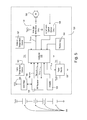
- FIG. 5 is a simplified block diagram of a motor drive unit of the battery-powered motorized window treatment of FIG. 1 ;
- FIGS. 6A and 6B are partial perspective views of the motor drive unit and a headrail of the motorized window treatment of FIG. 1 ;
- FIG. 7 is simplified frequency response of an RF filter of the motor drive unit of FIG. 5 ;
- FIG. 8 is a simplified timing diagram of an RF data transmission event and a sampling event of the motor drive unit of FIG. 5 ;
- FIG. 9 is a simplified flowchart of an RF signal receiving procedure executed by a controller of the motor drive unit of FIG. 5 ;
- FIG. 10 is a simplified flowchart of a command procedure executed periodically by the controller of the motor drive unit of FIG. 5 ;
- FIG. 11 is a simplified flowchart of a motor control procedure executed periodically by the controller of the motor drive unit of FIG. 5 ;
- FIG. 12 is a simplified diagram of a radio-frequency load control system including multiple motorized window treatments according to a second embodiment of the present invention.
- FIG. 13 is a simplified block diagram of a dimmer switch of the load control system of FIG. 12 according to the second embodiment of the present invention.
- FIG. 14 is a simplified block diagram of a dimmer switch of the load control system of FIG. 12 according to an alternate embodiment of the present invention.
- FIG. 15 is a simplified flowchart of an RF sampling rate selection procedure executed by a controller of one of the battery-powered motorized window treatments of FIG. 12 ;
- FIG. 16 is a simplified graph illustrating various signal strength thresholds of one of the battery-powered motorized window treatments of FIG. 12 ;
- FIG. 17 is a simplified flowchart of an RF monitoring procedure performed by a signal repeater of the load control system of FIG. 12 ;
- FIG. 18 is a simplified flowchart of an RF signal receiving procedure performed by a signal repeater of the load control system of FIG. 12 ;
- FIG. 19 is a simplified diagram of a RF load control system having two signal repeaters coupled together via a digital communication link according to a third embodiment of the present invention.
- FIG. 1 is a perspective view of a motorized window treatment system 100 having a battery-powered motorized window treatment 110 mounted in an opening 102 , for example, in front of a window 104 , according to a first embodiment of the present invention.
- the battery-powered motorized window treatment 110 comprises a covering material, for example, a cellular shade fabric 112 as shown in FIG. 1 .
- the cellular shade fabric 112 has a top end connected to a headrail 114 (that extends between two mounting plates 115 ) and a bottom end connected to a weighting element 116 .
- the mounting plates 115 may be connected to the sides of the opening 102 as shown in FIG.
- the cellular shade fabric 112 is able to hang in front of the window 104 , and may be adjusted between a fully-open position P FULLY-OPEN and a fully-closed position P FULLY-CLOSED to control the amount of daylight entering a room or space.
- the mounting plates 115 of the battery-powered motorized window treatment 110 could be mounted externally to the opening 102 (e.g., above the opening) with the shade fabric 112 hanging in front of the opening and the window 104 .
- the battery-powered motorized window treatment 110 could alternatively comprise other types of covering materials, such as, for example, a plurality of horizontally-extending slats (i.e., a Venetian or Persian blind system), pleated blinds, a roller shade fabric, or a Roman shade fabric.
- the motorized window treatment system 100 comprises a radio-frequency (RF) remote control 190 for transmitting RF signals 106 to the motorized window treatment 110 using, for example, a frequency-shift keying (FSK) modulation technique, to thus for control the operation of the motorized window treatment.
- the RF remote control 190 is operable to transmit digital messages including commands to control the motorized window treatment 710 via the RF signals 106 in response to actuations of a plurality of buttons, e.g., an open button 192 , a close button 194 , a raise button 195 , a lower button 196 , and a preset button 198 .
- a plurality of buttons e.g., an open button 192 , a close button 194 , a raise button 195 , a lower button 196 , and a preset button 198 .
- the motorized window treatment 110 controls the cellular shade fabric 112 to the fully-open position P FULLY-OPEN and the fully-closed position P FULLY-CLOSED in response to actuations of the open button 192 and the close button 194 of the remote control 190 , respectively.
- the motorized window treatment 110 raises and lowers the cellular shade fabric 112 in response to actuations of the raise button 195 and the lower button 196 , respectively.
- the motorized window treatment 110 controls the cellular shade fabric 112 to a preset position P PRESET in response to actuations of the preset button 198 .
- FIG. 2 is a perspective view and FIG. 3 is a right side view of the battery-powered motorized window treatment 110 with the cellular shade fabric 112 in the fully-open position P FULLY-OPEN .
- the motorized window treatment 110 comprises a motor drive unit 120 for raising and lowering the weighting element 116 and the cellular shade fabric 112 between the fully-open position P FULLY-OPEN and the fully-closed position P FULLY-CLOSED .
- the motorized window treatment 110 is able to control the amount of daylight entering the room.
- the headrail 114 of the motorized window treatment 110 comprises an internal side 122 and an opposite external side 124 , which faces the window 104 that the shade fabric 112 is covering.
- the motor drive unit 120 comprises an actuator 126 , which is positioned adjacent the internal side 122 of the headrail 114 may be actuated when a user is configuring the motorized window treatment 110 .
- the actuator 126 may be made of, for example, a clear material, such that the actuator may operate as a light pipe to conduct illumination from inside the motor drive unit 120 to thus be provide feedback to the user of the motorized window treatment 110 .
- the motor drive unit 120 is operable to determine a target position P TARGET for the weighting element 116 in response to commands included in the IR signals received from the remote control 190 and to subsequently control a present position P PRES of the weighting element to the target position P TARGET .
- a top side 128 of the headrail 114 is open, such that the motor drive unit 120 may be positioned inside the headrail and the actuator 126 may protrude slightly over the internal side 122 of the headrail.
- FIG. 4 is a front view of the battery-powered motorized window treatment 110 with the internal side 122 of the headrail 114 removed to show the motor drive unit 120 .
- the motorized window treatment 110 comprises lift cords 130 that extend from the headrail 114 to the weighting element 116 for allowing the motor drive unit 120 to raise and lower the weighting element.
- the motor drive unit 120 includes an internal motor 150 ( FIG. 5 ) coupled to drive shafts 132 that extend from the motor on each side of the motor and are each coupled to a respective lift cord spool 134 .
- the lift cords 130 are windingly received around the lift cord spools 134 and are fixedly attached to the weighting element 116 , such that the motor drive unit 120 is operable to rotate the drive shafts 132 to raise and lower the weighting element.
- the motorized window treatment 110 further comprises two constant-force spring assist assemblies 135 , which are each coupled to the drive shafts 132 adjacent to one of the two lift cord spools 134 .
- Each of the lift cord spools 134 and the adjacent constant-force spring assist assembly 135 are housed in a respective lift cord spool enclosure 136 as shown in FIG. 3 .
- the motor drive unit 120 could be located at either end of the headrail 114 and the motorized window treatment 110 could comprise a single drive shaft that extends along the length of the headrail and is coupled to both of the lift cord spools 134 .
- the battery-powered motorized window treatment 110 also comprises a plurality of batteries 138 (e.g., four D-cell batteries), which are electrically coupled in series.
- the seris-combination of the batteries 138 is coupled to the motor drive unit 120 for powering the motor drive unit.
- the batteries 138 are housed inside the headrail 114 and thus out of view of a user of the motorized window treatment 110 .
- the batteries 138 are mounted in two battery holders 139 located inside the headrail 114 , such that there are two batteries in each battery holder as shown in FIG. 4 .
- the batteries 138 provide the motorized window treatment 110 with a practical lifetime (e.g., approximately three years), and are typical “off-the-shelf” batteries that are easy and not expensive to replace.
- the motor drive unit 120 could comprise more batteries (e.g., six or eight) coupled in series or batteries of a different kind (e.g., AA batteries) coupled in series.
- FIG. 5 is a simplified block diagram of the motor drive unit 120 of the battery-powered motorized window treatment 110 .
- the motor drive unit 120 comprises a controller 152 for controlling the operation of the motor 150 , which may comprise, for example, a DC motor.
- the controller 152 may comprise, for example, a microprocessor, a programmable logic device (PLD), a microcontroller, an application specific integrated circuit (ASIC), a field-programmable gate array (FPGA), or any suitable processing device or control circuit.
- PLD programmable logic device
- ASIC application specific integrated circuit
- FPGA field-programmable gate array
- the controller 152 is coupled to an H-bridge motor drive circuit 154 for driving the motor 150 via a set of drive signals V DRIVE to control the weighting element 116 and the cellular shade fabric 112 between the fully-open position P FULLY-OPEN and the fully-closed position P FULLY-CLOSED .
- the controller 152 is operable to rotate the motor 150 at a constant rotational speed by controlling the H-bridge motor drive circuit 154 to supply a pulse-width modulated (PWM) drive signal having a constant duty cycle to the motor.
- PWM pulse-width modulated
- the controller 152 is able to change the rotational speed of the motor 150 by adjusting the duty cycle of the PWM signal applied to the motor and to change the direction of rotation of the motor by changing the polarity of the PWM drive signal applied to the motor.
- the controller 152 receives information regarding the rotational position and direction of rotation of the motor 150 from a rotational position sensor, such as, for example, a transmissive optical sensor circuit 155 .
- the rotational position sensor may also comprise other suitable position sensors or sensor arrangements, such as, for example, Hall-effect, optical, or resistive sensors.
- the controller 152 is operable to determine a rotational position of the motor 150 in response to the transmissive optical sensor circuit 155 , and to use the rotational position of the motor to determine a present position P PRES of the weighting element 116 .
- the controller 152 may comprise an internal non-volatile memory (or alternatively, an external memory coupled to the controller) for storage of the present position P PRES of the shade fabric 112 , the fully open position P FULLY-OPEN , and the fully closed position P FULLY-CLOSED .
- the operation of the H-bridge motor drive circuit 154 and the use of sensor devices to track the direction and speed of the motor drive unit 120 is described in greater detail in commonly-assigned U.S. Pat. No. 5,848,634, issued Dec. 15, 1998, entitled MOTORIZED WINDOW SHADE SYSTEM, and commonly-assigned U.S. Pat. No. 6,497,267, issued Dec. 24, 2002, entitled MOTORIZED WINDOW SHADE WITH ULTRAQUIET MOTOR DRIVE AND ESD PROTECTION, the entire disclosures of which are herein incorporated by reference.
- a user of the window treatment system 100 is able to adjust the position of the weighting element 116 and the cellular shade fabric 112 by using the remote control 190 to transmit commands to the motor drive unit 120 via the RF signals 106 .
- the motor drive unit 120 comprises an RF receiver 166 coupled to an antenna 168 (e.g., a wire antenna) for receiving the RF signals 106 .
- the antenna 168 is coupled to the RF receiver 166 via a surface acoustic wave (SAW) filter 169 (e.g., part number B3580 as manufactured by Epcos AG), which acts to filter RF noise as will be described in greater detail below.
- SAW surface acoustic wave
- the RF receiver 166 is operable to provide an RF data control signal V RF-DATA representative of the received RF signals 106 to a controller 152 , such that the controller is operable to control the H-bridge motor drive circuit 154 in response to the received signals.
- FIGS. 6A and 6B are partial perspective views of the motor drive unit 120 and the headrail 114 of the motorized window treatment 110 .
- the antenna 168 is adapted to extend from the motor drive unit 168 and is received in an elongated antenna wire carrier 170 .
- the antenna wire carrier 170 may be located in a first position immediately adjacent the motor drive unit 120 above the external side 124 of the headrail 114 .
- the antenna wire carrier 170 may be removed from the first position and re-located into a second position in which the antenna 168 is slightly offset (e.g., by a distance of approximately 0.4 inch) from the motor drive unit 120 as shown in FIG. 6B .
- the antenna wire carrier 170 comprises clips 172 that are adapted to snap onto the top edge of the external side 124 of the headrail 114 in the second position.
- the antenna wire carrier 170 provides a mechanical means for adjusting the RF sensitivity of the RF receiver 166 and thus the power consumed by the RF receiver 166 .
- the RF receiver 166 When the antenna wire carrier 170 is located in the second position (as shown in FIG. 6B ), the RF receiver 166 has an increased RF sensitivity (e.g., by approximately 3 dB), and is thus operable to receive more RF signals 106 than if the antenna wire carrier was located in the first position (as shown in FIG. 6A ).
- the increased RF sensitivity means that the RF receiver 166 will consume more power. Therefore, the antenna wire carrier 170 may be moved to the first position in which the RF receiver 166 has a reduced RF sensitivity, but consumes less power.
- the motor drive unit 120 receives power from the series-coupled batteries 138 , which provide a battery voltage V BATT .
- the batteries 138 may comprise D-cell batteries having rated voltages of approximately 1.5 volts, such that the battery voltage V BATT has a magnitude of approximately 6 volts.
- the H-bridge motor drive circuit 154 receives the battery voltage V BATT for driving the motor 150 .
- the controller 152 may be operable to operate in a sleep mode when the motor 150 is idle.
- the motor drive unit 120 further comprises a power supply 156 (e.g., a linear regulator) that receives the battery voltage V BATT and generates a DC supply voltage V CC for powering the controller 152 and other low-voltage circuitry of the motor drive unit.
- the controller 152 is coupled to the power supply 156 and generates a voltage adjustment control signal V ADJ for adjusting the magnitude of the DC supply voltage V CC between a first nominal magnitude (e.g., approximately 2.7 volts) and a second increased magnitude (e.g., approximately 3.3 volts).
- the power supply 156 may comprise, for example, an adjustable linear regulator having one or more feedback resistors that are switched in and out of the circuit by the controller 152 to adjust the magnitude of the DC supply voltage V CC .
- the controller 152 may adjust the magnitude of the DC supply voltage V CC to the second increased magnitude while the controller is driving the motor drive circuit 154 to rotate the motor 150 (since the controller may require an increased supply voltage to drive the motor drive circuit).
- the controller 152 adjusts the magnitude of the DC supply voltage V CC to the first nominal magnitude when the controller is not controlling the motor drive circuit 154 to rotate the motor 150 (e.g., when the controller is in the sleep mode).
- the magnitude of the idle currents drawn by the controller 152 , the IR receiver 166 , and other low-voltage circuitry of the motor drive unit 120 may be significantly smaller when these circuits are powered by the first nominal magnitude of the DC supply voltage V CC .
- the controller 152 is operable to determine that the magnitude of the battery voltage V BATT is getting low and to operate in a low-battery mode when the magnitude of the battery voltage V BATT drops below a first predetermined battery-voltage threshold V B-TH1 (e.g., approximately 1.0 volts per battery). For example, the controller 152 may control the motor drive circuit 154 so that the motor 150 is operated at a reduced speed (e.g., at half speed) to conserve battery power when the controller 152 is operating in the low-battery mode. This would serve as an indication to a consumer that the battery voltage V BATT is low and the batteries 138 need to be changed.
- a first predetermined battery-voltage threshold V B-TH1 e.g., approximately 1.0 volts per battery.
- the controller 152 may shut down electrical loads in the motor drive unit 120 (e.g., by disabling the IR receiver 166 and other low-voltage circuitry of the motor drive unit) and prevent movements of the cellular shade fabric 112 except to allow for at least one additional movement of the cellular shade fabric to the fully-open position P FULLY-OPEN . Having the cellular shade fabric 112 at the fully-open position P FULLY-OPEN allows for easy replacement of the batteries.
- the second predetermined battery-voltage threshold V B-TH2 may be sized to provide enough reserve energy in the batteries 138 to allow for the at least one additional movement of the cellular shade fabric 112 and the weighting element 116 to the fully-open position P FULLY-OPEN .
- the controller 152 may be operable to shut itself down such that no other circuits in the motor drive unit 120 consume any power in order to protect against any potential leakage of the batteries 138 .
- the motor drive unit 120 comprises an alternate (or supplemental) power source, such as a backup battery, e.g., a long-lasting battery (not shown), which generates a backup supply voltage V BACKUP (e.g., approximately 3.0 volts) for powering the controller 152 .
- the alternate power source provides the controller 152 with power when the batteries 138 are removed for replacement, or otherwise depleted, such that the position data relating to the position of the window treatment that is stored in the memory of the controller 152 is maintained.
- a large bus capacitor or an ultra-capacitor can be coupled to the controller 152 (rather than the backup battery), so that even when the batteries 138 are removed for replacement, an adequate charge will remain in the bus capacitor or ultra capacitor to maintain adequate voltage to keep the controller 152 charged for the period of time necessary to replace batteries 138 and thereby prevent loss of stored data in the memory of the controller.
- the motor drive unit 120 allows the motor drive unit 120 to keep track of the position of the weighting element 116 of the window treatment 110 even when the batteries 138 are removed and the window treatment is manually operated (i.e., pulled).
- the controller 152 continues to receive signals from transmissive optical sensor circuit 155 , even when the batteries 138 are removed. Because it remains powered, the controller 152 will continue to calculate the position of the window treatment 110 when manually adjusted. It should be pointed out that the window treatment 110 of the present invention allows a user at any time to manually adjust the position of the window treatment, and that the position of the window treatment is always calculated both when the window treatment is moved by the motor or manually.
- the motor drive unit 120 comprises an internal temperature sensor 160 that is located adjacent the internal side 122 of the headrail 114 (i.e., a room-side temperature sensor), and a external temperature sensor 162 that is located adjacent the external side 124 of the headrail (i.e., a window-side temperature sensor).
- the room-side temperature sensor 160 is operable to measure an interior temperature inside the room in which the motorized window treatment 110 is installed, while the external temperature sensor 162 is operable to measure an exterior temperature between the headrail 114 and the window 104 .
- the motor drive unit 120 further comprises a photosensor 164 , which is located adjacent the external side 124 of the headrail 114 , and is directed to measure the amount of sunlight that may be shining on the window 104 .
- the exterior (window-side) temperature sensor 162 may be implemented as a sensor label (external to the headrail 114 of the battery powered motorized window treatment 110 ) that is operable to be affixed to an inside surface of a window.
- the sensor label may be coupled to the motor drive unit 120 through low voltage wiring (not shown).
- the controller 152 receives inputs from the internal temperature sensor 160 , the external temperature sensor 162 , and the photosensor 164 .
- the controller 152 may operate in an eco-mode to control the position of the weighting element 116 and the cellular shade fabric 112 in response to the internal temperature sensor 160 , the external temperature sensor 162 , and the photosensor 164 , so as to provide energy savings.
- the controller 152 adjusts the amount of the window 104 covered by the cellular shade fabric 112 to attempt to save energy, for example, by reducing the amount of electrical energy consumed by other control systems in the building in which the motorized window treatment 110 is installed.
- the controller 152 may adjust the present position P PRES of the weighting element 116 to control the amount of daylight entering the room in which the motorized window treatment 110 is installed, such that lighting loads in the room may be turned off or dimmed to thus save energy.
- the controller 152 may adjust the present position P PRES of the weighting element 116 to control the heat flow through the window 104 in order to lighten the load on a heating and/or cooling system, e.g., a heating, air-conditioning, and ventilation (HVAC) system, in the building in which the motorized window treatment 110 is installed.
- a heating and/or cooling system e.g., a heating, air-conditioning, and ventilation (HVAC) system
- the motorized window treatment 110 and the RF remote control 190 may be easily programmed, such that the motorized window treatment 110 is responsive to actuations of the buttons 192 - 198 of the remote control 190 .
- the user may associate the remote control 190 with the motorized window treatment 110 by actuating the actuator 126 on the motor drive unit 120 and then pressing and holding, for example, the close button 194 on the remote control for a predetermined amount of time (e.g., approximately five seconds).
- the motorized window treatment is responsive to the RF signals 106 transmitted by the remote control.
- the user may program the preset position P PRESET of the motorized window treatment 110 by actuating the raise and lower buttons 195 , 196 of the remote control 190 to adjust the position of the weighting element 116 to the desired preset position, and then pressing and holding the preset button 198 for the predetermined amount of time.
- the user may also use the remote control 190 to program the upper and lower limits (i.e., the fully-open position P FULLY-OPEN and the fully-closed position P FULLY-CLOSED ) of the motorized window treatments 110 .
- the user actuates the actuator 126 on the motor drive unit 120 , and then simultaneously presses and holds the open button 192 and the raise button 195 of the remote control 190 for the predetermined amount of time (i.e., approximately five seconds).
- the user actuates the raise and lower buttons 195 , 196 of the remote control 190 to adjust the position of the weighting element 116 to the desired fully-closed position P FULLY-CLOSED , and then presses the close button 194 for the predetermined amount of time.
- the user actuates the raise and lower buttons 195 , 196 of the remote control to adjust the position of the weighting element 116 to the desired fully-open position P FULLY-OPEN , and then presses the open button 192 for the predetermined amount of time. The user can then press and hold the open button 192 and the raise button 195 of the remote control 190 for the predetermined amount of time to exit the limit programming mode.
- the RF receiver 166 and the controller 152 are both able to be put in a sleep mode (i.e., low-power mode) to conserve battery power.
- the RF receiver 166 is operable to wake-up periodically to sample (e.g., listen for) RF energy (i.e., RF signals 106 ) as will be described in greater detail below.
- the RF receiver is operable to wake up the controller 152 via an RF wake up signal V RF _ WAKE , such that the controller can begin processing the received RF signal.
- the RF receiver 166 wakes up the controller 152 in response to detecting any RF energy within a particular frequency band.
- the controller 152 wakes up in response to the RF wake up signal V RF _ WAKE .
- additional power is consumed by the controller (since the controller is fully powered when awake). This additional power consumption reduces the life of the batteries 138 , and as a result, it is optimal that the RF receiver 166 only wake up the controller 152 when necessary.
- FIG. 7 shows an example of a simplified frequency response of the SAW filter 169 .
- Frequency 180 illustrates an example frequency of the RF signals 106 .
- a frequency response 182 illustrates the response of only the antenna 168 and the RF receiver 166 (i.e., the response without the SAW filter 169 ). As shown in FIG. 7 , the frequency response 182 spans a wide range of frequencies (e.g., up to an 80 MHz band). As a result, the RF receiver 166 may be responsive to an interference event 184 .
- the RF receiver 166 (without the presence of the SAW filter 169 ) will detect the presence of the interference event 184 , and as a result, will cause the controller 152 to wake up via the RF wake up signal V RF _ WAKE .
- the controller 152 will appropriately disregard this interference event as it will recognize that it is not an RF signal 106 .
- the controller 152 consumes additional power to process the interference event 184 , and this negatively impacts the life of the batteries 138 .
- FIG. 7 also illustrates a SAW frequency response 186 which spans a much narrower band of frequencies than frequency response 182 .
- the SAW frequency response 186 does not encompass the interference event 184 .
- the SAW filter 169 filters interference events (e.g., such as interference event 184 ), and this allows the controller 152 to not wake up unnecessarily, thus further conserving the life of the batteries 138 .
- FIG. 8 is a simplified timing diagram of a data transmission event transmitted by the RF remote control 190 to the motorized window treatment 110 and a sampling event of the RF receiver 166 of the motor drive unit 120 .
- the remote control 190 transmits packets of data (e.g., the control information) via the RF signals 106 with each packet having a packet time period T PACKET (e.g, approximately 5 msec). Each packet of data is typically transmitted multiple times (e.g., up to twelve times) during a given data transmission event. Between each packet of data, there is a packet break time period T PKT _ BRK (e.g., approximately 75 ms), such that the remote control transmits digital messages at a transmission rate of approximately 12.5 packets per second.
- T PKT _ BRK packet break time period
- the RF receiver 166 of the motor drive unit 120 is operable to wake up and listen for any RF signals 106 during an RF sampling time period T SMPL-RF . If no RF signals 106 are detected during the RF sample time period T SMPL-RF , then the RF receiver 166 goes to sleep for an RF sleep time period T SLP-RF , such that the RF receiver samples the RF data at a sampling period T SAMPLE .
- the break time period T PKT _ BRK could not be a fixed value, but could be a varying or random time between each of the transmitted packets.
- the RF sample time period T SMPL-RF and the RF sleep time period T SLP-RF of the RF receiver 166 are sized appropriately to ensure that the RF sample time period T SMPL-RF coincides with at least one packet of a predetermined number of consecutive packets of a data transmission event.
- the RF sleep time period T SLP-RF of the RF receiver 166 can be much longer than the packet time period T PACKET .
- the RF sample time period T SMPL-RF can be significantly shorter than the packet time period T PACKET . Accordingly, the RF receiver 166 is operable to sleep for longer periods of time than prior art RF receivers, thus extending the lifetime of the batteries 138 of the motor drive unit 120 .
- the RF sample time period T SMPL-RF and the RF sleep time period T SLP-RF may be sized to be approximately 0.1 msec and 17.8 msec, respectively, to ensure that the RF sample time period T SMPL-RF coincides with at least one packet of five consecutive packets of a data transmission event.
- FIG. 8 Four packets 200 , 202 , 204 , and 206 of a data transmission event are shown in FIG. 8 .
- the remote control 190 begins to transmit the first packet 200 via the RF signals 106 .
- the first packet 200 is not received by the RF receiver 166 because the packet is transmitted during the RF sleep time period T SLP-RF (i.e., while the RF receiver is sleeping). In other words, the transmission of packet 200 does not coincide with an RF sampling event 210 of the RF receiver.
- the second packet 202 transmitted at time t 1 is not received by the RF receiver 166 because the packet is transmitted during the RF sleep time and does not coincide with one of the RF sampling events 210 of the RF receiver 166 .
- the third packet 204 is transmitted and is detected by the RF receiver 166 , such that the RF receiver wakes up the controller 152 . Since the controller 152 wakes up in the middle of the transmission of the third packet 204 (i.e., has missed the beginning of the transmission of the third packet), the controller is unable to properly process the data contained within the third packet. However, the controller 152 is operable to process the third packet 204 sufficiently to determine that a fourth packet 206 will be transmitted after the packet break time period T PKT _ BRK .
- the controller 152 and the RF receiver 166 are operable to enter the sleep mode for a snooze time period T SNOOZE , which may be approximately equal to or slightly less than the packet break time period T PKT _ BRK .
- the snooze time period T SNOOZE expires just before time t 3 , when the fourth packet 206 is transmitted.
- the duration of the snooze time period T SNOOZE is short enough to ensure that the RF receiver 166 is awake in time to receive the complete transmission of the fourth packet 206 .
- the RF receiver 166 and the controller 152 wake up, and the RF transceiver begins to listen to RF signals 106 for at least the RF sample time period T SMPL-RF . Because the RF receiver 166 and the controller 152 are awake at time t 3 when the remote control 190 begins to transmit the fourth packet 206 , the receiver is able to receive the entire packet. The receiver 166 remains on for an RF on time period T ON-RF and is operable to receive the entire packet 206 during an RF receiving event 212 , such that the controller 152 is able to properly process the packet 206 of data. Thus, because the RF receiver 166 and the controller 152 go back to sleep during the snooze time period T SNOOZE (and do not stay awake and fully powered while waiting for the next packet to be transmitted), the life of the batteries 138 is further conserved.
- FIG. 9 is a simplified flowchart of an RF signal receiving procedure 300 executed by the controller 152 after being awakened in response to the RF wake up signal V RF _ WAKE at step 310 .
- the controller 152 uses a SNOOZE flag to keep track of when the RF receiver 166 has been put to sleep for the snooze time period T SNOOZE . If the SNOOZE flag is not set at step 312 (i.e., the RF receiver 166 has not been put to sleep for the snooze time period T SNOOZE ) and the controller 152 does not detect an indication that an RF signal is present at step 314 , the controller 152 simply goes back to sleep at step 316 and the RF signal receiving procedure 300 exits.
- the controller 152 detects an RF signal at step 314 , the controller sets the SNOOZE flag at step 318 , and puts the RF receiver to sleep for the snooze time period T SNOOZE at step 320 . The controller 152 then goes back to sleep at step 316 , before the RF signal receiving procedure 300 exits.
- the controller 152 If the SNOOZE flag is set at step 312 (i.e., the RF receiver 166 has been put to sleep for the snooze time period T SNOOZE ), the controller 152 first clears the SNOOZE flag at step 322 and then gets ready to receive a digital message. If the RF receiver 766 is not receiving the start of a digital message at step 324 , the controller 152 puts the RF receiver to sleep for the RF sleep time period T SLP-RF at step 326 and goes back to sleep at step 316 , before the RF signal receiving procedure 300 exits.
- the controller 152 stores the received message in a receive (RX) buffer at step 328 and puts the RF receiver to sleep for the RF sleep time period T SLP-RF at step 330 .
- the RF signal receiving procedure 300 exits without the controller 152 being put back to sleep.
- the controller 152 will go back to sleep after processing the received digital message.
- FIG. 10 is a simplified flowchart of a command procedure 400 executed periodically by the controller 152 . If there is not a command in the RX buffer at step 410 , the command procedure 400 simply exits. However, if there is an open command in the RX buffer at step 412 , the controller 152 sets the target position P TARGET equal to the fully-open position P FULLY-OPEN at step 414 , before the command procedure 400 exits. If the received command is a close command at step 416 , the controller 152 sets the target position P TARGET equal to the fully-closed position P FULLY-CLOSED at step 418 and the command procedure 400 exits.
- the controller 152 respectively increases the target position P TARGET by a predetermined increment ⁇ P at step 422 or decreases the target position P TARGET by the predetermined increment ⁇ P at step 426 , before the command procedure 400 exits.
- FIG. 11 is a simplified flowchart of a motor control procedure 500 executed periodically by the controller 152 (e.g., every two msec). If the motor 150 is not presently rotating at step 510 and the present position P PRES is equal to the target position P TARGET at step 512 , the motor control procedure 500 simply exits without controlling the motor. However, if the motor 150 is not presently rotating at step 510 and the present position P PRES is not equal to the target position P TARGET at step 512 , the controller 152 controls the voltage adjustment control signal V ADJ to adjust the magnitude of the DC supply voltage V CC to the increased magnitude (i.e., approximately 3.3 volts) at step 514 .
- V ADJ the voltage adjustment control signal
- the controller 152 then begins to control the H-bridge drive circuit 154 to drive the motor 150 appropriately at step 516 , so as to move the weighting element 116 towards the target position P TARGET . If the motor 150 is presently rotating at step 510 , but the present position P PRES is not yet equal to the target position P TARGET at step 518 , the controller 512 continues to drive the motor 150 appropriately at step 520 and the motor control procedure 500 exits.
- the controller 152 stops driving the motor at step 522 and controls the voltage adjustment control signal V ADJ to adjust the magnitude of the DC supply voltage V CC to the nominal magnitude (i.e., approximately 2.7 volts) at step 524 .
- the controller 152 operates in a low-battery mode when the magnitude of the battery voltage V BATT is getting low. Specifically, if the magnitude of the battery voltage V BATT has dropped below the first battery-voltage threshold V B-TH1 at step 526 , the controller 152 begins at step 528 to operate in the low-battery mode during which the controller 152 will operate the motor at a reduced speed (i.e., at half speed).
- the controller 152 allows for one last movement of the cellular shade fabric 112 and the weighting element 116 to the fully-open position P FULLY-OPEN by setting a FINAL_MOVE flag in memory at step 532 .
- the controller 152 shuts down all unnecessary loads of the motor drive unit 120 (e.g., the external temperature sensor 162 , the photosensor 164 , the internal temperature sensor 160 , and the IR receiver 166 ) and prevents the motor 150 from moving the cellular shade fabric 112 and the weighting element 116 except for one last movement to the fully-open position P FULLY-OPEN .
- the controller 152 shuts itself down at step 538 such that no other circuits in the motor drive unit 120 consume any power to thus protect against any potential leakage of the batteries 138 . Otherwise, the motor control procedure 500 exits.
- the battery-powered motorized window treatment 110 is described in greater detail in U.S. patent application Ser. No. 13/415,084, filed Mar. 8, 2012, entitled MOTORIZED WINDOW TREATMENT, the entire disclosures of which are hereby incorporated by reference. While the battery-powered motorized window treatment 110 of the first embodiment comprises the cellular shade fabric 112 , the low-power RF receiver 166 could alternatively be used in other types of motorized window treatments, such as, for example, roller shades, draperies, Roman shades, Venetian blinds, and tensioned roller shade systems. An example of a roller shade system is described in greater detail in commonly-assigned U.S. Pat. No. 6,983,783, issued Jan.
- FIG. 12 is a simplified diagram of a radio frequency (RF) load control system 600 having multiple battery-powered motorized window treatments 610 according to a second embodiment of the present invention.
- the battery-powered motorized window treatments 610 of the second embodiment each have a very similar structure as the battery-powered motorized window treatment 110 of the first embodiment (as shown in FIG. 5 ).
- each of the motorized window treatments 610 of the second embodiment comprises a motor drive unit 620 having an RF transceiver (not shown) rather than the RF receiver 166 , such that the motorized window treatments are operable to both transmit and receive RF signals 606 .
- the control devices of the load control system 600 are operable to transmit packets using a packet time period T PACKET (e.g., approximately msec) and a packet break time period T PKT _ BRK (e.g., approximately 75 msec) as in the first embodiment.
- T PACKET e.g., approximately msec
- T PKT _ BRK packet break time period
- each motorized window treatment 610 is operable to enable the RF transceiver at a sampling period T SAMPLE (e.g., approximately 17.8 msec) to detect if an RF signal 602 is presently being transmitted.
- Each motorized window treatment 610 is operable put the RF transceiver to sleep for an RF sleep time period T SLP-RF that is much longer than the packet time period T PACKET (e.g., approximately 17.3 msec) and to enable an RF transceiver for the RF sample time period T SMPL-RF that is much shorter than the packet time period T PACKET (e.g., approximately 5 msec) so as to conserve battery power.
- the motorized window treatments 610 execute an RF signal receiving procedure similar to the RF signal receiving procedure 300 of the first embodiment as shown in FIG. 9 .
- the motorized window treatments 610 of the second embodiment do not put the RF transceiver to sleep for the snooze time period T SNOOZE after detecting an RF signal during the RF sample time period T SMPL-RF . Rather, the motorized window treatments 610 of the second embodiment simply remain on after detecting an RF signal during the RF sample time period T SMPL-RF .
- the load control system 600 also comprises a lighting control device, e.g., a wall-mountable dimmer switch 630 , which is coupled to an alternating-current (AC) power source 604 via a line voltage wiring 605 .
- the dimmer switch 630 is operable to adjust the amount of power delivered to a lighting load 632 to control the lighting intensity of the lighting load.
- the dimmer switch 630 is operable to transmit and receive digital messages via the RF signals 606 and is operable to adjust the lighting intensity of the lighting load 632 in response to the digital messages received via the RF signals.
- FIG. 13 is a simplified block diagram of the dimmer switch 630 according to the second embodiment of the present invention.
- the dimmer switch 630 comprises a hot terminal H that is adapted to be coupled to the AC power source 604 and a dimmed hot terminal DH adapted to be coupled to the lighting load 632 .
- the dimmer switch 630 comprises a controllably conductive device 710 coupled in series electrical connection between the AC power source 1002 and the lighting load 632 for control of the power delivered to the lighting load.
- the controllably conductive device 710 may comprise any suitable type of bidirectional semiconductor switch, such as, for example, a triac, a field-effect transistor (FET) in a rectifier bridge, or two FETs in anti-series connection.
- FET field-effect transistor
- the dimmer switch 630 comprises a controller 714 that is operatively coupled to a control input of the controllably conductive device 710 via a gate drive circuit 712 for rendering the controllably conductive device conductive or non-conductive to thus control the amount of power delivered to the lighting load 632 .
- the controller 714 is, for example, a microprocessor, but may alternatively be any suitable processing device, such as a programmable logic device (PLD), a microcontroller, or an application specific integrated circuit (ASIC).
- PLD programmable logic device
- ASIC application specific integrated circuit
- the controller 714 receives inputs from actuators 716 for controlling the present intensity of the lighting load 632 , and controls one or more visual indicators 718 for providing feedback of the present intensity of the lighting load.
- the controller 714 receives a control signal representative of the zero-crossing points of the AC mains line voltage of the AC power source 604 from a zero-crossing detector 720 .
- the controller 714 is operable to render the controllably conductive device 710 conductive and non-conductive at predetermined times relative to the zero-crossing points of the AC waveform using a phase-control dimming technique.
- the dimmer switch 630 further comprises a memory 722 for storing the present intensity of the lighting load 632 as well as other operating characteristics of the dimmer switch.
- the memory 722 may be implemented as an external integrated circuit (IC) or as an internal circuit of the controller 714 .
- the dimmer switch 630 also comprises a radio-frequency (RF) transceiver 724 and an antenna 726 for transmitting and receiving digital messages via RF signals.
- the controller 714 is operable to control the controllably conductive device 710 to adjust the intensity of the lighting load 632 in response to the digital messages received via the RF signals.
- the controller 714 may also transmit feedback information regarding the amount of power being delivered to the lighting load 632 via the digital messages included in the RF signals.
- the RF transceiver 724 could alternatively be implemented as an RF receiver for only receiving RF signals.
- the controller 714 enables the RF transceiver 724 at a sampling period T SAMPLE (e.g., approximately 17.8 msec) using, for example, a duty cycle of approximately 50%, such that the dimmer switch 630 enables the RF transceiver for an RF sample time period T SMPL-RF (e.g., approximately 8.9 msec), and puts the RF transceiver to sleep for an RF sleep time period T SLP-RF (e.g., approximately 8.9 msec). Accordingly, the RF sleep time period T SLP-RF used by the dimmer switch 630 is longer than the packet time period T PACKET so as to reduce the total power consumed by the dimmer switch 630 .
- T SAMPLE e.g., approximately 17.8 msec
- the dimmer switch 630 comprises a power supply 728 for generating a direct-current (DC) supply voltage V CC for powering the controller 714 , the memory 722 , the RF transceiver 724 , and the other low-voltage circuitry of the dimmer switch. Since the dimmer switch 630 does not have a connection to the neutral side of the AC power source 604 , the power supply 724 is operable to conduct a charging current through the lighting load 632 to generate the DC supply voltage V CC . Some lighting loads may be susceptible to flickering and other undesirable behavior if the magnitude of the charging current conducted through the lighting load is too large. Accordingly, the use of the RF sleep time period T SLP-RF that is longer than the packet time period T PACKET by the controller 714 helps to reduce the magnitude of the charging current conducted through the lighting load 632 and thus helps to avoid flickering in the lighting load.
- DC direct-current
- FIG. 14 is a simplified block diagram of a dimmer switch 630 ′ according to an alternate embodiment of the present invention.
- the dimmer switch 630 ′ is very similar to the dimmer switch 630 of the second embodiment.
- the dimmer switch 630 ′ has an earth ground terminal GND that is adapted to be coupled to earth ground.
- the zero-crossing detector 620 and the power supply 628 of the dimmer switch 630 ′ are coupled between the hot terminal H and the earth ground terminal GND (rather than the dimmed hot terminal DH). Accordingly, the power supply 728 conducts the charging current through the earth ground terminal GND (rather than the lighting load 632 ).
- the magnitude of the total current conducted through the earth ground terminal GND by the dimmer switch 630 ′ is limited by standards and regulations in most countries.
- the use of the RF sleep time period T SLP-RF that is longer than the packet time period T PACKET by the controller 714 helps to reduce the magnitude of the charging current conducted through the earth ground terminal GND.
- the load control system 600 further comprises a wall-mounted button keypad 640 and a battery-powered tabletop button keypad 642 .
- the wall-mounted button keypad 640 is powered from the AC power source 604 via the line voltage wiring 605
- the tabletop button keypad 642 is a battery-powered device. Both of the keypads 640 , 642 transmit digital messages to the dimmer switch 630 via the RF signals 606 in order to provide for remote control of the lighting load 632 .
- each of the keypads 640 , 642 is operable to receive digital status messages via the RF signals 606 from the dimmer switch 630 in order to display the status (i.e., on/off state and/or intensity level) of the lighting load 632 .
- the load control system 600 further comprises a battery-powered remote control 644 which is operable to transmit digital messages to the dimmer switch 630 via the RF signals 606 in order to provide for remote control of the lighting load 632 .
- the wall-mounted button keypad 640 , the tabletop button keypad 642 , and the remote control 644 are also operable to adjust the present position P PRES of the battery-powered motorized window treatments 610 by transmitting digital messages via the RF signals 606 .
- the battery-powered motorized window treatments 610 may be operable to transmit status information to the wall-mounted keypad 640 and tabletop button keypad 642 .
- the load control system 600 further comprises a battery-powered wireless occupancy sensor 646 for detecting an occupancy condition (i.e., the presence of an occupant) or a vacancy condition (i.e., the absence of an occupant) in the space in which the occupancy sensor is mounted.
- the occupancy sensor 646 is operable to wirelessly transmit digital messages via the RF signals 606 to the dimmer switch 630 in response to detecting the occupancy condition or the vacancy condition in the space.
- the occupancy sensor 646 may transmit a digital message to the dimmer switch 630 to cause the dimmer switch to turn on the lighting load 632 , and in response to detecting a vacancy condition in the space, transmit a digital message to the dimmer switch to cause the dimmer switch to turn off the lighting load.
- the occupancy sensor 646 could be implemented as a vacancy sensor, such that the dimmer switch 630 would only operate to turn off the lighting load 632 in response to receiving the vacant commands from the vacancy sensor. Examples of RF load control systems having occupancy and vacancy sensors are described in greater detail in commonly-assigned U.S. Pat. No.
- the load control system 600 further comprises a battery-powered daylight sensor 648 for measuring an ambient light intensity in the space in which the daylight sensor in mounted.
- the daylight sensor 648 wirelessly transmits digital messages via the RF signals 606 to the dimmer switch 630 .
- the daylight sensor 648 may transmit a digital message to the dimmer switch 630 to cause the dimmer switches to increase the intensities of the lighting load 632 if the ambient light intensity detected by the daylight sensor 648 is less than a setpoint light intensity, and to decrease the intensities of the lighting load if the ambient light intensity is greater than the setpoint light intensity.
- the packet break time period T PKT _ BRK of the packets transmitted by the daylight sensor 648 may be variable, for example, as a function of the measured light intensity.
- the battery-powered motorized window treatments 610 may be operable to receive digital messages from the occupancy sensor 646 and the daylight sensor 648 via the RF signals 606 and to adjust the present position of the window treatments.
- RF load control systems having daylight sensors are described in greater detail in commonly-assigned U.S. patent application Ser. No. 12/727,956, filed Mar. 19, 2010, entitled WIRELESS BATTERY-POWERED DAYLIGHT SENSOR, and U.S. patent application Ser. No. 12/727,923, filed Mar. 19, 2010, entitled METHOD OF CALIBRATING A DAYLIGHT SENSOR, the entire disclosures of which are hereby incorporated by reference.
- the load control system 600 further comprises a battery-powered temperature control device 650 (e.g., a thermostat) that is operable to control a heating and/or cooling system, e.g., a heating, ventilation, and air conditioning (HVAC) system 652 .
- the temperature control device 650 may be coupled to the HVAC system 652 via an HVAC communication link 654 , e.g., a digital communication link (such as an RS-485 link, an Ethernet link, or a BACnet® link), or alternatively via a wireless communication link (such as an RF communication link).
- the temperature control device 650 may comprise an internal temperature sensor for determining a present temperature in the space in which the temperature control device is located.
- the temperature control device 650 transmits appropriate digital messages to the HVAC system 652 to control the present temperature in the building towards a setpoint temperature.
- the HVAC communication link 654 could comprise a more traditional analog control link for simply turning the HVAC system 652 on and off.
- the temperature control device 650 comprises a user interface, e.g., a touch screen 656 , for displaying the present temperature and the setpoint temperature, and for receiving user inputs for adjusting the setpoint temperature.
- the temperature control device 650 is operable to receive RF signals 606 from a wireless temperature sensor 656 for determining the present temperature in the space, for example, at a location away from the temperature control device 650 .
- the motor drive units 620 of each of the motorized window treatments 610 may be operable to transmit the temperature measurements from the internal and/or external temperature sensors 160 , 162 to the temperature control device 650 .
- Each of the battery-powered devices of the load control system 600 i.e., the tabletop button keypad 642 , the remote control 644 , the occupancy sensor 646 , the daylight sensor 648 , and the temperature control device 650 ) is operable to enable their respective RF transceivers at a sampling period T SAMPLE (e.g., approximately 17.8 msec) to detect if an RF signal 602 is presently being transmitted as described above for the motorized window treatments 610 .
- T SAMPLE e.g., approximately 17.8 msec
- Each of these battery-powered devices is operable put its RF transceiver to sleep for an RF sleep time period T SLP-RF that is much longer than the packet time period T PACKET (e.g., approximately 5 msec) and to enable the RF transceiver for the RF sample time period T SMPL-RF that is much shorter than the packet time period T PACKET (e.g., approximately 17.3 msec) so as to conserve battery power.
- T SLP-RF that is much longer than the packet time period T PACKET (e.g., approximately 5 msec) and to enable the RF transceiver for the RF sample time period T SMPL-RF that is much shorter than the packet time period T PACKET (e.g., approximately 17.3 msec) so as to conserve battery power.
- the load control system 600 could also comprise other types of input devices and load control devices that each may put its RF transceiver to sleep for an RF sleep time period T SLP-RF that is much longer than the packet time period T PACKET .
- the additional types of input devices may comprise battery-powered remote controls, a temperature sensors, humidity sensors, security sensors, proximity sensors, keypads, key fobs, cell phones, smart phones, tablets, personal digital assistants, personal computers, timeclocks, audio-visual controls, safety devices, and central control transmitters.
- the additional types of load control devices may comprise, for example, an electronic dimming ballast for a fluorescent lamp; a driver for a light-emitting diode (LED) light source; a screw-in luminaire that includes a light source and an integral load regulation circuit; a switching device for turning one or more appliances on and off; a plug-in load control device for controlling one or more plug-in loads; a motor control device for controlling a motor load, such as a ceiling fan or an exhaust fan.
- LED light-emitting diode
- the load control system 600 further comprises signal repeaters 660 A, 660 B, which are operable to retransmit any received digital messages to ensure that all of the control devices of the load control system receive all of the RF signals 606 .
- the load control system 600 may comprise, for example, one to five signal repeaters depending upon the physical size of the system.
- Each of the control devices, (e.g., the motorized window treatments 610 , the dimmer switch 630 , the tabletop button keypad 642 , the wall-mounted button keypad 640 , the occupancy sensor 646 , the daylight sensor 648 , and the temperature control device 650 ) of the load control system 600 are located within the communication range of at least one of the signal repeaters 660 A, 660 B.
- the signal repeaters 660 A, 660 B are powered by the AC power source 604 via power supplies 662 plugged into electrical outlets 664 .
- one of the signal repeaters operates as a “main” repeater (i.e., a main controller) to facilitate the operation of the load control system 600 .
- the main repeater 660 A has a database, which defines the operation of the load control system, stored in memory.
- the main repeater 660 A is operable to determine which of the lighting load 632 is energized and to use the database to control any visual indicators of the dimmer switch 630 and the keypads 642 , 640 accordingly to provide the appropriate feedback to the user of the load control system 600 .
- the control devices of the load control system may be operable to transmit status information to the signal repeaters 660 A, 660 B.
- the motor drive unit 620 of each of the motorized window treatments 610 may be operable to transmit a digital message representative of the magnitude of the respective battery voltage to the signal repeaters 660 A, 660 B, a digital message including a low-battery indication to the signal repeaters when operating in the low-battery mode, or a digital message representative of the present position P PRESET of the motorized window treatment.
- the load control system 600 may comprise one to five signal repeaters depending upon the physical size of the system.
- the control devices of the load control system 600 are each operable to adjust the RF sampling period T SAMPLE in response to the total number N RPTR of signal repeaters within the load control system 600 .
- each control device is operable to adjust the RF sleep time period T SLP-RF , while keeping the RF sampling time period T SMPL-RF constant.
- the control devices adjust the respective sampling periods because packets of data may be transmitted differently via the RF signals 606 depending on the number of repeaters in the load control system 600 .
- the packet break time period T PKT _ BRK of the data transmissions may vary in response to the number of repeaters to ensure that the signal repeaters in the load control system 600 have sufficient time to propagate a given packet. Because the packet break time period T PKT _ BRK is a factor in appropriately sizing the RF sleep time period T RF _ SLEEP of each of the control devices to ensure that an RF sampling event coincides with a packet transmission as discussed above with respect to FIG. 8 , the RF sleep time period T RF _ SLEEP also varies accordingly if the packet break time period T PKT _ BRK of a transmitted packet varies.
- FIG. 15 is a simplified flowchart of an RF sampling rate selection procedure 800 that may be executed by any of control devices of the load control system 600 , e.g., the motor drive unit 620 .
- this sampling rate procedure 800 may be executed during a configuration of the motor drive unit 612 .
- that signal repeater will send a message to the motor drive unit 620 to inform the motor drive unit of the total number of repeaters N RPTR in the load control system.
- the motor drive unit 620 determines whether it has received a packet containing the number of repeaters N RPTR .
- the motor drive unit 620 In the event that the motor drive unit 620 has not received such a packet, then the motor drive unit assumes that it is operating in a load control system that contains no signal repeaters. As a result, the motor drive unit 620 uses a first RF sleep time period value T SLP-RF1 (e.g., approximately 17.8 msec) as the RF sleep time period T SLP-RF at step 812 before the RF sampling rate selection procedure 1100 exits.
- T SLP-RF1 e.g., approximately 17.8 msec
- the motor drive unit 620 determines whether the number of repeaters N RPTR is greater than three at step 814 . If the number of repeaters N RPTR is not greater than three at step 814 , the motor drive unit 620 uses the first RF sleep time period value T SLP-RF1 (e.g., approximately 17.8 msec) as the RF sleep time period T SLP-RF at step 816 before the sampling rate selection procedure 800 exits.
- T SLP-RF1 e.g., approximately 17.8 msec
- the motor drive unit 620 uses a second RF sleep time period value T SLP-RF2 (e.g., approximately 16.3 msec) as the RF sleep time period T SLP-RF at step 818 before the RF sampling rate selection procedure 800 exits.
- T SLP-RF2 e.g., approximately 16.3 msec
- the RF sampling rate selection procedure 800 ensures that the motor drive unit 620 adjusts its RF sampling rate T SAMPLE in response to the number of repeaters in the load control system 600 to optimize reliability, response time, and battery life.
- the other battery-powered devices of the load control system 600 may also execute the RF sampling rate selection procedure 800 .
- the RF transceivers of the control devices of the load control system 600 are characterized by a signal strength threshold which is used to detect the transmitted RF signals 606 .
- the RF transceiver of each of the control devices of the load control system 600 is characterized by an adjustable signal strength threshold.
- FIG. 16 is a simplified graph illustrating various signal strength thresholds of, for example, the RF transceiver of one of the motor drive units 620 .
- FIG. 16 illustrates two signal strength thresholds of the RF transceiver: a first threshold 860 (i.e., an extended battery threshold) and a second threshold 870 (i.e., an extended range threshold) having a lower magnitude than the first threshold.
- the first and second thresholds 860 , 870 reside between a noise floor 880 and a signal strength 850 of the nearest signal repeater (e.g., one of the signal repeaters 660 A, 660 B). While FIG. 16 is described with reference to the motorized window treatments 620 , the other battery-powered devices of the load control system 600 (i.e., the tabletop button keypad 642 , the remote control 644 , the occupancy sensor 646 , the daylight sensor 648 , and the temperature control device 650 ) may also have RF transceivers having adjustable signal strength thresholds.
- a user may be operable to select the signal strength of the RF transceiver as having either the first threshold 860 or the second threshold 870 .
- the RF transceiver is operable to detect RF signals of a lower signal strength which can improve the range performance of the RF transceiver (i.e., the RF transceiver can detect RF signals sent from control devices that are located farther away).
- the second threshold 870 may cause the RF transceiver to be more sensitive to noise events as the noise floor 880 may occasionally exceed the second threshold.
- the RF transceiver Each time the RF transceiver receives any RF energy (RF signals 606 , RF noise, etc.) that exceeds the second threshold 870 during the RF sampling time period T SMPL-RF , the RF transceiver wakes up the controller of the motor drive unit 620 , such that the controller then consumes additional power which ultimately reduces the life of the batteries of the motor drive unit.
- the RF transceiver uses the first threshold 860 to detect RF signals 606 , the RF transceiver is less likely to detect RF signals having a lower signal strength, but is less susceptible to noise events.
- the RF transceiver Because the RF transceiver only responds to RF energy (RF signals 606 , RF noise, etc.) that exceeds the first threshold 860 , the RF transceiver does not wake up the controller as frequently as when the second threshold 870 is used. As a result, the life of the batteries can be further extended when the RF transceiver uses the first threshold 660 .
- the first and second thresholds 860 , 870 may be predetermined values.
- the first threshold 860 may have a value of approximately ⁇ 90 dBm and the second threshold 670 may have a value of approximately ⁇ 97 dBm.
- the value of the adjustable threshold of the RF transceiver could be determined automatically during the configuration procedure of the motor drive unit 620 .
- the RF transceiver may be operable to detect an average magnitude of the noise floor 880 and may also be able to detect a magnitude of the signal strength 850 of the nearest signal repeater 660 A, 660 B, and then provide these magnitudes to the controller of the motor drive unit.
- the controller may then calculate an optimal value of a threshold for the RF transceiver that will preserve battery life and provide appropriate range performance. For example, the controller may halve the sum of the magnitude of the noise floor 880 and the magnitude of the signal strength 850 of the nearest signal repeater to calculate the value of the threshold for the RF transceiver.
- the load control system 600 may be operable to prompt a user, e.g., through a programming interface (not shown), to add another signal repeater to the system. By adding another signal repeater to the system, the magnitude of the signal strength of the nearest signal repeater may increase, thus increasing the calculated threshold of the RF transceiver. As a result, the battery life of each of the motor drive units 620 may be further extended.
- the motor drive units 620 are each assigned to a particular frequency channel such that each motor drive can receive RF signals 606 transmitted on that frequency channel.
- the motor drive units 620 will each detect any packet of information that is transmitted on the respective assigned frequency channel—even if that packet does not contain data that is addressed to the motor drive unit.
- the RF transceiver of each motor drive unit 620 begins to detect a packet transmitted on the assigned frequency channel, the RF transceiver will wake up the controller of the motor drive unit as previously described. The controller will then process the packet to determine whether it must adjust the present position P PRES of the motorized window treatment 610 .
- the controller will take no further action and will go back to sleep. However, because the controller woke up to process the packet, the controller consumed power unnecessarily, and negatively impacted the life of the batteries of the motor drive unit 620 .
- the load control system 600 comprises many devices that are operable to send and/or receive RF signals 606 , there can be a very large number of packets regularly transmitted within the system. Many of these packets may not be addressed to the motor drive units 620 , and as a result, need not be processed by the controller of each of the motor drive units.
- the battery-power motorized window treatments 610 may be configured to only listen to RF signals 606 transmitted on an alternate channel distinct from the channels used by the other devices of the load control system 600 .
- FIG. 17 is a simplified flowchart of an RF monitoring procedure 900 performed by a main repeater (e.g., the signal repeater 660 A) of the load control system 600 .
- the main repeater 660 A configures all of the control devices of the load control system 600 to use a given frequency channel (e.g., frequency channel A).
- the main repeater 660 A is operable to monitor a number N of RF packets transmitted within a given time frame during normal operation.
- the main repeater 660 A compares the number N of RF packets to a predetermined maximum number N MAX to determine whether the load control system 600 has a high amount of traffic on frequency channel A.
- the main repeater 660 A configures all of the battery-powered motorized window treatments 610 to listen only to an alternate frequency channel (e.g., frequency channel B). Otherwise, the main repeater 660 A simply exits the RF monitoring procedure 900 without changing the channel configuration of the battery-powered motorized window treatments 610 . Alternatively, the main repeater 660 A could simply configure all battery-powered motorized window treatments 610 to use the alternate frequency channel (i.e., frequency channel B) in lieu of executing the RF monitoring procedure 900 .
- an alternate frequency channel e.g., frequency channel B
- FIG. 18 is a simplified flowchart of an RF signal receiving procedure 1000 performed by the signal repeaters (e.g., the signal repeater 660 A) of the load control system 600 during normal operation when an alternate frequency is in use.
- the signal repeater 660 A receives a packet transmitted on frequency channel A.
- the signal repeater 660 A determines whether the received packet is addressed to at least one of the battery-powered motorized window treatments 610 . If the packet is not addressed to any of the battery-powered motorized window treatments 610 (e.g., the packet is addressed to the dimmer switch 630 ), then the repeater 660 A simply retransmits the packet on channel A at step 1014 before the RF signal receiving procedure 1000 exits.
- the signal repeater 660 A determines that the received packet is addressed to at least one of the battery-powered motorized window treatments 610 , the signal repeater changes its frequency channel from channel A to channel B at step 1016 and transmits the received packet on frequency channel B to the battery-powered motorized window treatments 610 at step 1018 . Finally, the signal repeater 660 A changes its frequency channel from channel B back to channel A at step 1020 and the RF signal receiving procedure 1000 exits.
- FIG. 19 is a simplified diagram of a RF load control system 1100 having two signal repeaters 1160 A, 1160 B coupled together via a digital communication link 1166 according to a third embodiment of the present invention.
- the first signal repeater 1160 A is configured to transmit and receive packets via the RF signals 606 using only the primary frequency channel A
- the second signal repeater 1160 B is configured to transmit and receive packets via the RF signals 606 using only the alternate frequency channel B.
- the first and second signal repeaters 1160 A, 1160 B are operable to transmit digital messages to each other via the digital communication link 1166 , which may comprise, for example, a wired communication link, such as an RS-485 link or an Ethernet link, link, or alternatively may comprise a wireless communication link, such as an RF communication link.
- the digital communication link 1166 may comprise, for example, a wired communication link, such as an RS-485 link or an Ethernet link, link, or alternatively may comprise a wireless communication link, such as an RF communication link.
- the signal repeater 1160 A transmits a digital message (e.g., including the data from the packet) to the second signal repeater 1160 B via the digital communication link 1166 .
- the second signal repeater 1160 B Upon receiving the information via the digital communication link 1160 B, the second signal repeater 1160 B transmits the packets to the battery-powered motorized window treatments 610 via the RF signals 606 using the alternate frequency B.
- the packets transmitted to the motorized window treatments 610 by the second signal repeater 1160 B include the same (or similar) data as the packets that were received by the first signal repeater 1160 A.
- the battery-powered motorized window treatments 610 only listen to RF signals 606 transmitted on the alternate frequency channel B distinct from the channel used by the other devices of the load control system 600 in order to further preserve the battery life of the battery-powered window treatments.
Priority Applications (3)
| Application Number | Priority Date | Filing Date | Title |
|---|---|---|---|
| US13/415,537 US10041292B2 (en) | 2011-03-11 | 2012-03-08 | Low-power radio-frequency receiver |
| US16/055,806 US11753866B2 (en) | 2011-03-11 | 2018-08-06 | Low-power radio-frequency receiver |
| US18/301,517 US11946316B2 (en) | 2011-03-11 | 2023-04-17 | Low-power radio-frequency receiver |
Applications Claiming Priority (4)
| Application Number | Priority Date | Filing Date | Title |
|---|---|---|---|
| US201161451960P | 2011-03-11 | 2011-03-11 | |
| US201161530799P | 2011-09-02 | 2011-09-02 | |
| US201161547319P | 2011-10-14 | 2011-10-14 | |
| US13/415,537 US10041292B2 (en) | 2011-03-11 | 2012-03-08 | Low-power radio-frequency receiver |
Related Child Applications (1)
| Application Number | Title | Priority Date | Filing Date |
|---|---|---|---|
| US16/055,806 Continuation US11753866B2 (en) | 2011-03-11 | 2018-08-06 | Low-power radio-frequency receiver |
Publications (2)
| Publication Number | Publication Date |
|---|---|
| US20120281606A1 US20120281606A1 (en) | 2012-11-08 |
| US10041292B2 true US10041292B2 (en) | 2018-08-07 |
Family
ID=45841682
Family Applications (9)
| Application Number | Title | Priority Date | Filing Date |
|---|---|---|---|
| US13/415,537 Active 2035-09-03 US10041292B2 (en) | 2011-03-11 | 2012-03-08 | Low-power radio-frequency receiver |
| US13/415,084 Active US8950461B2 (en) | 2011-03-11 | 2012-03-08 | Motorized window treatment |
| US13/415,246 Active 2032-05-21 US8851141B2 (en) | 2011-03-11 | 2012-03-08 | Battery-powered motorized window treatment having a service position |
| US14/478,296 Active US9249624B2 (en) | 2011-03-11 | 2014-09-05 | Battery-powered motorized window treatment having a service position |
| US14/579,024 Active US9605478B2 (en) | 2011-03-11 | 2014-12-22 | Motorized window treatment |
| US14/980,549 Active US9745796B2 (en) | 2011-03-11 | 2015-12-28 | Battery-powered motorized window treatment having a service position |
| US15/689,653 Active 2032-08-30 US10590700B2 (en) | 2011-03-11 | 2017-08-29 | Battery-powered motorized window treatment having a service position |
| US16/055,806 Active 2033-09-28 US11753866B2 (en) | 2011-03-11 | 2018-08-06 | Low-power radio-frequency receiver |
| US18/301,517 Active US11946316B2 (en) | 2011-03-11 | 2023-04-17 | Low-power radio-frequency receiver |
Family Applications After (8)
| Application Number | Title | Priority Date | Filing Date |
|---|---|---|---|
| US13/415,084 Active US8950461B2 (en) | 2011-03-11 | 2012-03-08 | Motorized window treatment |
| US13/415,246 Active 2032-05-21 US8851141B2 (en) | 2011-03-11 | 2012-03-08 | Battery-powered motorized window treatment having a service position |
| US14/478,296 Active US9249624B2 (en) | 2011-03-11 | 2014-09-05 | Battery-powered motorized window treatment having a service position |
| US14/579,024 Active US9605478B2 (en) | 2011-03-11 | 2014-12-22 | Motorized window treatment |
| US14/980,549 Active US9745796B2 (en) | 2011-03-11 | 2015-12-28 | Battery-powered motorized window treatment having a service position |
| US15/689,653 Active 2032-08-30 US10590700B2 (en) | 2011-03-11 | 2017-08-29 | Battery-powered motorized window treatment having a service position |
| US16/055,806 Active 2033-09-28 US11753866B2 (en) | 2011-03-11 | 2018-08-06 | Low-power radio-frequency receiver |
| US18/301,517 Active US11946316B2 (en) | 2011-03-11 | 2023-04-17 | Low-power radio-frequency receiver |
Country Status (4)
| Country | Link |
|---|---|
| US (9) | US10041292B2 (fr) |
| EP (7) | EP2733299B1 (fr) |
| CN (6) | CN103620150B (fr) |
| WO (3) | WO2012125423A1 (fr) |
Cited By (6)
| Publication number | Priority date | Publication date | Assignee | Title |
|---|---|---|---|---|
| US20170260808A1 (en) * | 2011-03-11 | 2017-09-14 | Lutron Electronics Co., Inc. | Motorized window treatment |
| US20180347271A1 (en) * | 2011-03-11 | 2018-12-06 | Lutron Electronics Co., Inc. | Low-Power Radio-Frequency Receiver |
| US10655386B2 (en) | 2011-03-11 | 2020-05-19 | Lutron Technology Company Llc | Motorized window treatment |
| WO2020219984A1 (fr) | 2019-04-25 | 2020-10-29 | Lutron Technology Company Llc | Dispositif de commande comrepnant une radio secondaire pour réveiller une radio primaire |
| US10827383B2 (en) | 2018-02-23 | 2020-11-03 | Lutron Technology Company Llc | Collision detection method |
| WO2023114526A1 (fr) | 2021-12-17 | 2023-06-22 | Lutron Technology Company Llc | Commande d'une position d'un élément de recouvrement d'un habillage de fenêtre motorisé |
Families Citing this family (212)
| Publication number | Priority date | Publication date | Assignee | Title |
|---|---|---|---|---|
| US8451116B2 (en) | 2009-03-27 | 2013-05-28 | Lutron Electronics Co., Inc. | Wireless battery-powered daylight sensor |
| US8760293B2 (en) * | 2009-03-27 | 2014-06-24 | Lutron Electronics Co., Inc. | Wireless sensor having a variable transmission rate |
| US8975778B2 (en) * | 2009-07-30 | 2015-03-10 | Lutron Electronics Co., Inc. | Load control system providing manual override of an energy savings mode |
| US9249623B2 (en) | 2010-02-23 | 2016-02-02 | Qmotion Incorporated | Low-power architectural covering |
| US8659246B2 (en) | 2010-02-23 | 2014-02-25 | Homerun Holdings Corporation | High efficiency roller shade |
| US9194179B2 (en) | 2010-02-23 | 2015-11-24 | Qmotion Incorporated | Motorized shade with the transmission wire passing through the support shaft |
| US8575872B2 (en) | 2010-02-23 | 2013-11-05 | Homerun Holdings Corporation | High efficiency roller shade and method for setting artificial stops |
| DE102010027746A1 (de) * | 2010-04-14 | 2011-10-20 | Robert Bosch Gmbh | Verfahren zum Betreiben einer Schließvorrichtung sowie eine Schließvorrichtung |
| US9045939B2 (en) | 2011-03-11 | 2015-06-02 | Lutron Electronics Co., Inc. | Battery-powered motorized window treatment having a service position |
| US9645465B2 (en) | 2011-03-16 | 2017-05-09 | View, Inc. | Controlling transitions in optically switchable devices |
| US8705162B2 (en) | 2012-04-17 | 2014-04-22 | View, Inc. | Controlling transitions in optically switchable devices |
| US9454055B2 (en) | 2011-03-16 | 2016-09-27 | View, Inc. | Multipurpose controller for multistate windows |
| US9981529B2 (en) | 2011-10-21 | 2018-05-29 | Honeywell International Inc. | Actuator having a test mode |
| WO2013059674A1 (fr) | 2011-10-21 | 2013-04-25 | View, Inc. | Atténuation de choc thermique dans des fenêtres pouvant être colorées |
| US10113762B2 (en) * | 2011-11-09 | 2018-10-30 | Honeywell International Inc. | Actuator having an adjustable running time |
| EP2798787B1 (fr) | 2011-12-28 | 2018-10-24 | Lutron Electronics Co., Inc. | Système de régulation de charge avec unités à commande indépendante réagissant à un régulateur à diffusion |
| US20130233496A1 (en) * | 2012-03-08 | 2013-09-12 | Peter W. Ogden, JR. | Motorized window treatment having a belt drive |
| US11635666B2 (en) | 2012-03-13 | 2023-04-25 | View, Inc | Methods of controlling multi-zone tintable windows |
| US11950340B2 (en) | 2012-03-13 | 2024-04-02 | View, Inc. | Adjusting interior lighting based on dynamic glass tinting |
| US8931541B2 (en) | 2012-03-16 | 2015-01-13 | Lutron Electronics Co., Inc. | Motorized drive unit assembly for a shade system |
| US11674843B2 (en) | 2015-10-06 | 2023-06-13 | View, Inc. | Infrared cloud detector systems and methods |
| US10048561B2 (en) | 2013-02-21 | 2018-08-14 | View, Inc. | Control method for tintable windows |
| US9638978B2 (en) | 2013-02-21 | 2017-05-02 | View, Inc. | Control method for tintable windows |
| US8723455B2 (en) * | 2012-04-25 | 2014-05-13 | Homerun Holdings Corporation | Quick change battery arrangement for motorized shade |
| CH706787A2 (fr) * | 2012-07-24 | 2014-01-31 | Daniele Oppizzi | Store photovoltaïque. |
| US20140055061A1 (en) * | 2012-08-24 | 2014-02-27 | Lutron Electronics Co., Inc. | Battery Powered Control Device For Driving A Load With A Pulse Width Modulated Signal |
| US9933761B2 (en) | 2012-11-30 | 2018-04-03 | Lutron Electronics Co., Inc. | Method of controlling a motorized window treatment |
| EP2743442B1 (fr) | 2012-12-12 | 2016-04-27 | FAKRO PP Spolka z ograniczona odpowiedzialnoscia | Store à enroulement automatique pour fenêtres de toit et procédé de commande de celui-ci |
| US9115537B2 (en) * | 2013-02-15 | 2015-08-25 | Lutron Electronics Co., Inc. | Battery-powered roller shade system |
| US11966142B2 (en) | 2013-02-21 | 2024-04-23 | View, Inc. | Control methods and systems using outside temperature as a driver for changing window tint states |
| US11719990B2 (en) | 2013-02-21 | 2023-08-08 | View, Inc. | Control method for tintable windows |
| US11960190B2 (en) | 2013-02-21 | 2024-04-16 | View, Inc. | Control methods and systems using external 3D modeling and schedule-based computing |
| US9169690B2 (en) * | 2013-03-14 | 2015-10-27 | Lutron Electronics Co., Inc. | Window treatment having backlighting |
| US20140262057A1 (en) | 2013-03-15 | 2014-09-18 | Lutron Electronics Co., Inc. | Method of controlling a window treatment using a light sensor |
| CA2906790C (fr) * | 2013-03-15 | 2017-08-15 | Springs Window Fashions, Llc | Train d'engrenages de systeme d'elevation et de commande motorisee de revetement de fenetre |
| WO2014169173A1 (fr) * | 2013-04-12 | 2014-10-16 | Qmotion Incorporated | Couverture architecturale à faible énergie |
| US9103157B2 (en) * | 2013-04-13 | 2015-08-11 | Qmotion Incorporated | Spring counterbalance apparatus and method |
| US9459603B2 (en) * | 2013-04-14 | 2016-10-04 | Atid, Llc | Tactical illusion device and related methods |
| US9488000B2 (en) | 2013-04-15 | 2016-11-08 | Lutron Electronics Co., Inc. | Integrated accessible battery compartment for motorized window treatment |
| USD747896S1 (en) | 2013-04-15 | 2016-01-26 | Lutron Electronics Co., Inc. | Roller shade |
| US9670724B2 (en) * | 2013-04-17 | 2017-06-06 | The Watt Stopper, Inc. | System and method for manual and motorized manipulation of an architectural covering |
| US9992841B2 (en) | 2013-04-19 | 2018-06-05 | Lutron Electronics Co., Inc. | Systems and methods for controlling color temperature |
| US9590453B2 (en) | 2013-06-11 | 2017-03-07 | Lutron Electronics Co., Inc. | Configuring communications for a load control system |
| US9384657B2 (en) * | 2013-06-13 | 2016-07-05 | The Watt Stopper, Inc. | Architectural covering cradle system, multifunction remote and method of use |
| US20150013920A1 (en) * | 2013-07-09 | 2015-01-15 | Qmotion Incorporated | Battery powered venetian and roman shade system and methods of use |
| US10017985B2 (en) | 2013-08-14 | 2018-07-10 | Lutron Electronics Co., Inc. | Window treatment control using bright override |
| WO2015042289A1 (fr) | 2013-09-18 | 2015-03-26 | Lutron Electronics Co., Inc. | Système de traitement à fenêtre motorisée silencieuse |
| FR3011698B1 (fr) * | 2013-10-09 | 2015-10-23 | Valeo Embrayages | Actionneur electrique pour systeme de transmission de vehicule |
| WO2015074068A1 (fr) | 2013-11-18 | 2015-05-21 | Gordon's Window Decor, Inc. | Système de commande à libération rapide pour revêtement d'ouverture architecturale |
| US10149369B2 (en) | 2013-11-21 | 2018-12-04 | Lutron Electronics Co., Inc. | Method of associating wireless control devices |
| WO2015077621A1 (fr) * | 2013-11-21 | 2015-05-28 | Draper, Inc. | Store de fenêtre assisté par ressorts |
| CN103645656A (zh) * | 2013-11-22 | 2014-03-19 | 成都捷康特科技有限公司 | 智能窗帘远程控制装置 |
| US9386669B2 (en) | 2013-12-26 | 2016-07-05 | Lutron Electronics Co., Inc. | Controlling light intensity at a location |
| KR101918343B1 (ko) * | 2014-01-03 | 2018-11-13 | 데 요 컴퍼니 리미티드 | 모터 작동식 창문 가리개 |
| US9903155B1 (en) * | 2014-01-10 | 2018-02-27 | Anita Ann Wagner | Window brackets for providing efficient removal of window screens |
| US9382756B2 (en) | 2014-01-31 | 2016-07-05 | Lutron Electronics Co., Inc. | Cable guided shade system |
| US9540871B2 (en) * | 2014-04-08 | 2017-01-10 | David R. Hall | Motorized gearbox assembly with through-channel design |
| US9869124B2 (en) * | 2014-04-08 | 2018-01-16 | David R. Hall | Motorized gearbox assembly with through-channel design |
| US20150296348A1 (en) * | 2014-04-14 | 2015-10-15 | Lear Corporation | Polling between wireless device and vehicle transceivers |
| MX2016014149A (es) * | 2014-04-28 | 2017-06-14 | Delta T Corp | Control de condición ambiental basado en condiciones detectadas y métodos relacionados. |
| CA2950735C (fr) | 2014-05-30 | 2018-11-06 | Lutron Electronics Co., Inc. | Dispositif de commande sans fil |
| US10358869B2 (en) * | 2014-06-17 | 2019-07-23 | Crestron Electronics, Inc. | Shading control network using a control network |
| CN106661918B (zh) * | 2014-06-23 | 2019-08-27 | 路创技术有限责任公司 | 响应多个传感器控制电动窗用品 |
| US10407982B2 (en) | 2014-06-24 | 2019-09-10 | Lutron Technology Company Llc | Retention systems for window treatment installations |
| US9408282B1 (en) * | 2014-07-21 | 2016-08-02 | Astro, Inc. | Multi-purpose lightbulb |
| US9784417B1 (en) * | 2014-07-21 | 2017-10-10 | Astro, Inc. | Multi-purpose lightbulb |
| FR3024176B1 (fr) * | 2014-07-25 | 2016-08-05 | Somfy Sas | Procede de controle d'un actionneur d'enroulement, actionneur d'enroulement configure pour un tel procede et installation de fermeture ou de protection solaire comprenant un tel actionneur |
| CN105472099A (zh) * | 2014-08-13 | 2016-04-06 | 中兴通讯股份有限公司 | 温度处理方法及装置 |
| US10094169B2 (en) | 2014-11-01 | 2018-10-09 | Lutron Electronics Co., Inc. | Interlocking pivotable fascia for motorized window treatment |
| CA2870983A1 (fr) | 2014-11-06 | 2016-05-06 | Etapa Window Fashions Inc | Moteur adapte pour les cordes de store enrouleur |
| WO2016088919A1 (fr) * | 2014-12-04 | 2016-06-09 | (주) 트라이너스 | Système de microphone sans fil |
| WO2016131081A1 (fr) * | 2015-02-19 | 2016-08-25 | Rollease Acmeda Pty Ltd | Ensemble limiteur pour store |
| CN107580802B (zh) | 2015-03-13 | 2019-11-19 | 路创技术有限责任公司 | 具有响应于外部传感器受控的照亮部分的控制装置 |
| US10392860B2 (en) * | 2015-03-17 | 2019-08-27 | Eric Barnett | Systems and methods for controlling the blinds |
| CN107636247A (zh) * | 2015-04-30 | 2018-01-26 | 夏普株式会社 | 采光装置、采光系统 |
| CN212296178U (zh) | 2015-05-08 | 2021-01-05 | 路创技术有限责任公司 | 电动窗上用品 |
| US9763303B2 (en) | 2015-05-15 | 2017-09-12 | Lutron Electronics Co., Inc. | Keypad interface for programming a load control system |
| AU2016204260B2 (en) | 2015-06-25 | 2021-04-08 | Hunter Douglas Inc. | Shutter assembly with motorized louver drive system |
| US10519713B2 (en) * | 2015-07-01 | 2019-12-31 | Hunter Douglas Inc. | Static mitigation end cap for a covering for an architectural opening |
| TWI746446B (zh) | 2015-07-07 | 2021-11-21 | 美商唯景公司 | 用於可著色窗戶之控制方法 |
| AT516630B1 (de) * | 2015-07-10 | 2016-07-15 | Ifn-Holding Ag | Beschattungsvorrichtung |
| JP6594076B2 (ja) * | 2015-07-22 | 2019-10-23 | 文化シヤッター株式会社 | 開閉装置 |
| ITUB20152680A1 (it) * | 2015-07-30 | 2017-01-30 | Pellini Spa | Sistema per il comando di una tenda a veneziana. |
| CN105741413B (zh) * | 2015-08-05 | 2019-04-26 | 深圳怡化电脑股份有限公司 | 存取款设备及其动态校正传感器,以及校正方法和装置 |
| WO2017049126A1 (fr) | 2015-09-17 | 2017-03-23 | Lutron Electronics Co., Inc. | Serrure de support de montage |
| CN105125045B (zh) * | 2015-09-30 | 2018-04-06 | 深圳万物智联技术有限公司 | 智能窗帘的控制装置 |
| US10863846B2 (en) | 2015-10-02 | 2020-12-15 | Axis Labs Inc. | External motor drive system for window covering system with continuous cord loop |
| CA3000108A1 (fr) * | 2015-10-02 | 2017-04-06 | Axis Labs Inc. | Systeme d'entrainement de moteur externe pour systeme de couvre-fenetre a boucle de cordon continu |
| US11255722B2 (en) | 2015-10-06 | 2022-02-22 | View, Inc. | Infrared cloud detector systems and methods |
| MX2018004266A (es) | 2015-10-09 | 2018-08-09 | Lutron Electronics Co | Dispositivo de control inalambrico que tiene una placa frontal con señales iluminadas. |
| EP3369136B1 (fr) | 2015-10-30 | 2021-06-23 | Lutron Technology Company LLC | Dispositif de communication sans fil à double antenne dans un système de commande de charge |
| CA3002658C (fr) | 2015-10-30 | 2023-05-02 | Lutron Electronics Co., Inc. | Dispositif de commande sans fil comprenant une antenne eclairee par de la lumiere visible |
| CN108605402B (zh) | 2015-12-11 | 2020-09-18 | 路创技术有限责任公司 | 具有可见光传感器的负载控制系统 |
| CN105471352B (zh) * | 2016-01-05 | 2019-05-31 | 珠海格力电器股份有限公司 | 电机调速方法、装置、系统及智能环保桶 |
| US10648231B2 (en) * | 2016-01-14 | 2020-05-12 | Hunter Douglas, Inc. | Methods and apparatus for controlling architectural opening coverings in more than one mode |
| CN205605050U (zh) * | 2016-01-22 | 2016-09-28 | 亿丰综合工业股份有限公司 | 窗帘的阻尼装置 |
| US10326641B2 (en) * | 2016-01-26 | 2019-06-18 | Motorola Mobility Llc | Using RF energy on an uplink channel to transition an unpowered access point to a power-up state |
| US20170223802A1 (en) * | 2016-02-03 | 2017-08-03 | Honeywell International Inc. | Camera-aided controller of illumination |
| EP3205808B1 (fr) | 2016-02-10 | 2020-12-23 | VKR Holding A/S | Agencement d'écran avec un support de fixation |
| MX2018009491A (es) | 2016-02-12 | 2019-06-12 | Cornellcookson Llc | Puerta contra incendios de tela. |
| CN114680420A (zh) | 2016-03-15 | 2022-07-01 | 耐克创新有限合伙公司 | 用于自动化鞋类平台的马达控制 |
| US10819158B2 (en) | 2016-04-01 | 2020-10-27 | Lutron Technology Company Llc | Wireless power supply for electrical devices |
| US10379208B2 (en) | 2016-05-02 | 2019-08-13 | Lutron Technology Company Llc | Fan speed control device |
| US10136549B2 (en) | 2016-05-02 | 2018-11-20 | Lutron Electronics Co., Inc. | Fan speed control device |
| US11202351B2 (en) | 2016-06-03 | 2021-12-14 | Lutron Technology Company Llc | Control device for controlling multiple operating characteristics of an electrical load |
| US9834983B1 (en) * | 2016-06-07 | 2017-12-05 | David R. Hall | Intelligent window blind adjustment |
| CA3030145C (fr) | 2016-07-05 | 2023-10-10 | Lutron Electronics Co., Inc. | Systeme de commande de charge de retention d'etat |
| WO2018009579A1 (fr) | 2016-07-05 | 2018-01-11 | Lutron Electronics Co., Inc. | Commande de groupes de charges électriques par l'intermédiaire de messages de multidiffusion et/ou de monodiffusion |
| US11437814B2 (en) | 2016-07-05 | 2022-09-06 | Lutron Technology Company Llc | State retention load control system |
| CN106050108B (zh) * | 2016-07-25 | 2018-05-08 | 苏州鸿仁窗饰有限公司 | 用于窗帘拉绳收放的收放装置及收放式窗帘 |
| CN106089002A (zh) | 2016-07-25 | 2016-11-09 | 苏州鸿仁窗饰有限公司 | 绕线组件及收放式窗帘 |
| US10608440B2 (en) * | 2016-08-31 | 2020-03-31 | Te Connectivity Corporation | Control circuit configured to determine when a direct current component in an alternating current power line passes a designated threshold |
| CN108778067A (zh) * | 2016-08-31 | 2018-11-09 | 彭革新 | 一种可调节跨度的电动收容装置 |
| USD797060S1 (en) * | 2016-09-28 | 2017-09-12 | AXIS Labs, Inc. | Lift-control device for window coverings |
| CN110169203B (zh) | 2016-10-21 | 2021-07-20 | 路创技术有限责任公司 | 电池供电的遥控设备 |
| CA3208177A1 (fr) | 2016-10-21 | 2018-04-26 | Lutron Technology Company Llc | Commande de groupes de charges electriques |
| CN106761295B (zh) * | 2016-12-01 | 2018-04-20 | 重庆金华兴门业有限公司 | 一种复合门的制造工艺 |
| US10420185B2 (en) | 2016-12-05 | 2019-09-17 | Lutron Technology Company Llc | Systems and methods for controlling color temperature |
| CN110463351B (zh) | 2016-12-09 | 2022-03-08 | 路创技术有限责任公司 | 具有可见光传感器的负载控制系统 |
| US10753145B2 (en) | 2016-12-11 | 2020-08-25 | David T. Biedermann | Motorized shade apparatus |
| US11060353B2 (en) | 2016-12-15 | 2021-07-13 | Lutron Technology Company Llc | Coupling mechanism for use with a roller tube of a window treatment |
| US10407977B2 (en) | 2016-12-28 | 2019-09-10 | Hunter Douglas Inc. | Motorized shutter assembly |
| TWI759419B (zh) * | 2017-02-06 | 2022-04-01 | 美商漢特道格拉斯股份有限公司 | 用於減小馬達總成中之雜訊之方法及設備 |
| CN106908172B (zh) * | 2017-02-27 | 2019-05-21 | 深圳华远微电科技有限公司 | 无线测温系统的信号处理方法和系统 |
| CN110536998B (zh) | 2017-03-03 | 2021-07-13 | 路创技术有限责任公司 | 被配置用于眩光检测和控制机动窗帘的可见光传感器 |
| US10337240B2 (en) * | 2017-03-13 | 2019-07-02 | Hall Labs Llc | Window blinds with capacitor in slats to charge slats and clean the air |
| US11293224B2 (en) | 2017-03-14 | 2022-04-05 | Roll-A-Shade, Inc. | Intelligent automated motorized window treatment with increased energy efficiency and method of using same |
| US11203899B2 (en) | 2018-03-12 | 2021-12-21 | Roll-A-Shade Inc. | Solar-powered intelligent automated motorized window treatment with increased energy efficiency and method of using same |
| US20180266176A1 (en) * | 2017-03-14 | 2018-09-20 | David R. Hall | Motorized Roll-Up Window Shade |
| US10087680B1 (en) * | 2017-03-28 | 2018-10-02 | Hall Labs Llc | Battery-powered window covering |
| US10273747B2 (en) * | 2017-04-07 | 2019-04-30 | Hall Labs Llc | Window covering with hybrid shade-battery |
| TWI628350B (zh) * | 2017-04-14 | 2018-07-01 | 德侑股份有限公司 | 電動窗簾及其致動機構 |
| US20180313558A1 (en) * | 2017-04-27 | 2018-11-01 | Cisco Technology, Inc. | Smart ceiling and floor tiles |
| WO2018200978A2 (fr) | 2017-04-28 | 2018-11-01 | Lutron Electronics Co., Inc. | Support de montage de traitement de fenêtre |
| US11187033B2 (en) | 2017-05-08 | 2021-11-30 | Lutron Technology Company Llc | Variable-stiffness roller shade tube |
| US10965154B2 (en) | 2017-05-11 | 2021-03-30 | Lutron Technology Company Llc | Detecting actuations of buttons of a control device |
| CN107242828A (zh) * | 2017-06-20 | 2017-10-13 | 上海魅质智能科技有限公司 | 马桶盖驱动装置及驱动方法 |
| US20190071926A1 (en) * | 2017-09-07 | 2019-03-07 | David R. Hall | Local and Cloud Based Wireless Control of Motorized Window Coverings |
| US10574757B2 (en) | 2017-10-04 | 2020-02-25 | Resilience Magnum IP, LLC | Self aware lights that self-configure |
| US11596118B2 (en) | 2017-10-04 | 2023-03-07 | Resilience Magnum IP, LLC | Intelligent horticulture light |
| US10510251B2 (en) | 2017-10-04 | 2019-12-17 | Resilience Magnum IP, LLC | Parking space light |
| US11244563B2 (en) | 2017-10-04 | 2022-02-08 | Resilience Magnum IP, LLC | Flow management light |
| US10794603B2 (en) | 2017-10-04 | 2020-10-06 | Resilience Magnum IP, LLC | Intelligent purifier light |
| US10867486B2 (en) | 2017-10-04 | 2020-12-15 | Resilience Magnum IP, LLC | Hospitality light |
| US10251242B1 (en) | 2017-10-04 | 2019-04-02 | Resilience Magnum IP, LLC | Information and hub lights |
| US10408988B2 (en) | 2017-10-04 | 2019-09-10 | Resilience Magnum IP, LLC | Techniques for enhanced diffusion lighting |
| CN107994739B (zh) * | 2017-12-15 | 2020-03-31 | 西安航天动力测控技术研究所 | 一种基于齿槽转矩的制动设计方法 |
| CA3088867C (fr) * | 2018-01-05 | 2023-08-08 | Lutron Technology Company Llc | Alimentation electrique supplementaire pour un dispositif alimente par batterie |
| KR102051896B1 (ko) * | 2018-01-09 | 2019-12-06 | (주)한국윈텍 | 코드리스 블라인드 장치 |
| WO2019157390A1 (fr) | 2018-02-09 | 2019-08-15 | Lutron Technology Company Llc | Procédure d'autotest pour un dispositif de commande |
| US11147146B2 (en) * | 2018-03-27 | 2021-10-12 | Signify Holding B.V. | Sensor-based lighting system with integrated wireless signal repeater |
| US11002071B2 (en) | 2018-03-29 | 2021-05-11 | Crestron Electronics, Inc. | Architectural roller shade housing with adjustable battery compartment |
| WO2019204981A1 (fr) * | 2018-04-24 | 2019-10-31 | Lei Zhenbang | Rideau électrique |
| CN108412407A (zh) * | 2018-04-24 | 2018-08-17 | 雷振邦 | 电动窗帘 |
| CN110545065A (zh) * | 2018-05-28 | 2019-12-06 | 杭州三花研究院有限公司 | 一种控制方法及控制系统 |
| EP3807813A1 (fr) | 2018-06-14 | 2021-04-21 | Lutron Technology Company LLC | Capteur de lumière visible configuré pour la détection d'éblouissement et la commande de traitements de fenêtre motorisée |
| WO2020041488A1 (fr) | 2018-08-21 | 2020-02-27 | Lutron Technology Company Llc | Commande de groupes de charges électriques |
| MX2021002187A (es) | 2018-08-24 | 2021-08-11 | Lutron Tech Co Llc | Dispositivo para detectar ocupantes. |
| CA3110522A1 (fr) | 2018-08-24 | 2020-02-27 | Lutron Technology Company Llc | Dispositif de comptage d'occupants |
| AU2019332824B2 (en) * | 2018-08-28 | 2022-07-28 | Milwaukee Electric Tool Corporation | Battery-powered stand-alone motor unit |
| US20200076014A1 (en) * | 2018-09-04 | 2020-03-05 | GM Global Technology Operations LLC | Continuous hands-free battery monitoring and control |
| EP3847336A1 (fr) | 2018-09-04 | 2021-07-14 | Lutron Technology Company LLC | Commande de couleur d'éclairage et de traitements de fenêtre motorisée |
| EP3850917A1 (fr) | 2018-09-11 | 2021-07-21 | Lutron Technology Company LLC | Dispositif de commande configuré pour fournir un retour d'informations visuel |
| CA3118434A1 (fr) | 2018-10-31 | 2020-05-07 | Lutron Technology Company Llc | Systeme de commande de charge a maintien d'etat |
| FR3088952B1 (fr) * | 2018-11-26 | 2021-03-12 | Simu | Procédé de commande en fonctionnement d’une installation domotique de fermeture, d’occultation ou de protection solaire et installation domotique associée |
| MX2021006727A (es) | 2018-12-07 | 2021-09-21 | Lutron Tech Co Llc | Fuente de luz para mantener parámetros circadianos y permitir flexibilidad al cambiar la intensidad y la temperatura de color. |
| CN109684890B (zh) * | 2018-12-26 | 2022-03-29 | 江苏恒宝智能系统技术有限公司 | 一种降低功耗的方法及装置 |
| CN113661499A (zh) | 2019-02-19 | 2021-11-16 | 路创技术有限责任公司 | 被配置用于检测眩光状况的可见光传感器 |
| US11414926B2 (en) | 2019-02-20 | 2022-08-16 | Mechoshade Systems, Llc | Maintenance and operation of a window shade system |
| EP3935708A1 (fr) | 2019-03-04 | 2022-01-12 | Lutron Technology Company LLC | Distribution de puissance en courant continu dans un système de commande |
| CN110005331B (zh) * | 2019-04-19 | 2022-05-24 | 健达创智科技股份有限公司 | 一种无线电动帘控制系统 |
| CN114009100A (zh) | 2019-04-19 | 2022-02-01 | 路创技术有限责任公司 | 具有自适应传输功率的控制装置 |
| US11434690B2 (en) * | 2019-05-08 | 2022-09-06 | Lutron Technology Company Llc | Lift cord spool for a motorized treatment |
| CN114009150A (zh) | 2019-05-17 | 2022-02-01 | 路创技术有限责任公司 | 在持续过度用户交互之后的灯同步 |
| WO2020236633A1 (fr) | 2019-05-17 | 2020-11-26 | Lutron Technology Company Llc | Commande de groupes de charges électriques |
| CN110260438B (zh) * | 2019-06-11 | 2022-03-29 | 青岛海尔空调器有限总公司 | 智能窗和用于智能窗的控制方法 |
| WO2020257738A1 (fr) | 2019-06-21 | 2020-12-24 | Lutron Technology Company Llc | Sous-programme de démarrage coordonné pour dispositifs de commande d'un réseau |
| CA3147032C (fr) | 2019-07-12 | 2024-01-16 | Lutron Technology Company Llc | Store a rouleau motorise a barre d'ourlet intelligente |
| CN110412920A (zh) * | 2019-08-06 | 2019-11-05 | 珠海格力电器股份有限公司 | 一种电动窗帘的控制方法 |
| EP4013937A1 (fr) | 2019-08-13 | 2022-06-22 | Lutron Technology Company LLC | Habillage de fenêtre à garniture réglable |
| CN110568422B (zh) * | 2019-08-30 | 2022-08-23 | 上海禾赛科技有限公司 | SiPM接收器和激光雷达的动态阈值调节方法以及激光雷达 |
| CN114761659A (zh) | 2019-10-04 | 2022-07-15 | 路创技术有限责任公司 | 覆盖材料和电动窗上用品的控制 |
| CN115023907A (zh) | 2019-12-02 | 2022-09-06 | 路创技术有限责任公司 | 百分位基底链路鉴定 |
| US11770324B1 (en) | 2019-12-02 | 2023-09-26 | Lutron Technology Company Llc | Processing advertisement messages in a mesh network |
| CN115023927A (zh) | 2019-12-20 | 2022-09-06 | 路创技术有限责任公司 | 处置网状网络中的装置的失去或移除 |
| USD923589S1 (en) * | 2020-04-15 | 2021-06-29 | Ningbo Sunfree Motor Technology Company Limited | Curtain controller |
| US11486193B2 (en) * | 2020-04-30 | 2022-11-01 | San Hsin Plastech Co., Ltd. | Solar adjustment apparatus and method of operating the same |
| DE202020102492U1 (de) * | 2020-05-04 | 2020-05-28 | Abb Schweiz Ag | Regler für ein Steuergerät zur Ansteuerung einer Lichtschutzvorrichtung |
| WO2021226526A1 (fr) | 2020-05-08 | 2021-11-11 | Lutron Technology Company, LLC | Attribution de dispositifs de routeur dans un réseau maillé |
| CN115804151A (zh) | 2020-05-15 | 2023-03-14 | 路创技术有限责任公司 | 在噪声源周围定位网络的路由器 |
| WO2021237188A1 (fr) | 2020-05-22 | 2021-11-25 | Lutron Technology Company Llc | Traitement de fenêtre actionné par batterie |
| EP4158985A1 (fr) | 2020-05-29 | 2023-04-05 | Lutron Technology Company LLC | Dispositif de commande ayant un seuil de transmission adaptatif |
| CA3180970A1 (fr) | 2020-07-13 | 2022-01-20 | Galen Edgar Knode | Communication de messages a l'aide d'une technique de multidiffusion coordonnee |
| CN112160673B (zh) * | 2020-09-28 | 2022-01-04 | 广州科通达信息科技有限公司 | 一种具有WiFi插座的窗扇组件 |
| CN112502599A (zh) * | 2020-10-16 | 2021-03-16 | 张世兵 | 一种窗户和窗帘一体机 |
| FR3115555B1 (fr) * | 2020-10-26 | 2023-01-06 | Somfy Activites Sa | Procédé de commande en fonctionnement d’un dispositif d’occultation et dispositif d’occultation associé |
| TWI771810B (zh) * | 2020-11-25 | 2022-07-21 | 億豐綜合工業股份有限公司 | 電動窗簾之控制方法 |
| EP4252490A1 (fr) | 2020-11-30 | 2023-10-04 | Lutron Technology Company LLC | Capteur pour détecter des conditions d'éblouissement |
| WO2022115811A1 (fr) | 2020-11-30 | 2022-06-02 | Lutron Technology Company Llc | Capteur destiné à détecter des conditions d'éblouissement |
| CN112232463B (zh) * | 2020-12-15 | 2021-04-02 | 广州智慧城市发展研究院 | 低功耗rfid读写系统及方法 |
| CN112731821B (zh) * | 2020-12-18 | 2023-03-24 | 卧安科技(深圳)有限公司 | 一种设备运动方法及电子设备 |
| WO2022226363A2 (fr) | 2021-04-22 | 2022-10-27 | Lutron Technology Company Llc | Configuration et commande de systèmes de commande de charge |
| USD996858S1 (en) | 2021-05-02 | 2023-08-29 | Lutron Technology Company Llc | Window treatment |
| US11840886B2 (en) | 2021-05-12 | 2023-12-12 | Ryse Inc. | External motor drive system adjusting for creep in window covering system with continuous cord loop |
| WO2022266522A1 (fr) | 2021-06-18 | 2022-12-22 | Lutron Technology Company Llc | Capteur pour mesurer des conditions environnementales dans un environnement d'utilisateur |
| US20230019165A1 (en) * | 2021-07-19 | 2023-01-19 | Visionary Enterprises LLC | Solar panel window shade device and system |
| CA3219381A1 (fr) | 2021-10-22 | 2023-04-27 | Rhodes B. Baker | Dispositif de detection d'occupant |
| WO2023114528A2 (fr) | 2021-12-17 | 2023-06-22 | Lutron Technology Company Llc | Commande de charge basée sur des gestes |
| CN114913673A (zh) * | 2022-03-03 | 2022-08-16 | 武江 | 一种燃气报警、关断装置的安全控制方法 |
| TWI802352B (zh) * | 2022-03-30 | 2023-05-11 | 慶豐富實業股份有限公司 | 無線電性控制的上樑及電動窗簾 |
| WO2024006194A1 (fr) * | 2022-06-29 | 2024-01-04 | Hunter Douglas, Inc. | Revêtement de structure architecturale |
| CN117162859B (zh) * | 2023-11-02 | 2024-01-02 | 太原理工大学 | 一种挂轨巡检机器人的自动充换电装置 |
Citations (106)
| Publication number | Priority date | Publication date | Assignee | Title |
|---|---|---|---|---|
| US2802523A (en) | 1954-05-24 | 1957-08-13 | Lorentzen Hardware Mfg Corp | Installation providing movement of venetian blind away from window |
| US3169006A (en) | 1963-02-01 | 1965-02-09 | Levolor Lorentzen Inc | Venetian blind installation and bracket therefor |
| US4864588A (en) | 1987-02-11 | 1989-09-05 | Hillier Technologies Limited Partnership | Remote control system, components and methods |
| US4932037A (en) | 1987-02-11 | 1990-06-05 | Hillier Technologies Limited Partnership | Remote control system, components and methods |
| US4995053A (en) | 1987-02-11 | 1991-02-19 | Hillier Technologies Limited Partnership | Remote control system, components and methods |
| US5239205A (en) | 1991-05-02 | 1993-08-24 | Heath Company | Wireless multiple position switching system |
| US5297144A (en) | 1991-01-22 | 1994-03-22 | Spectrix Corporation | Reservation-based polling protocol for a wireless data communications network |
| US5387905A (en) | 1992-10-05 | 1995-02-07 | Motorola, Inc. | Mutli-site group dispatch call method |
| US5454077A (en) | 1990-04-17 | 1995-09-26 | Somfy | Communication system between a plurality of transmitters and receivers having relays responsive to those identifying codes of transmitters contained in its respective table memory |
| EP0767551A2 (fr) | 1995-10-02 | 1997-04-09 | Telia Ab | Méthode pour augmenter la capacité dans un système DECT |
| WO1997018501A1 (fr) | 1995-11-15 | 1997-05-22 | Harmonic Design, Inc. | Actionneur monte sur rail de direction pour couvre-fenetre |
| EP0793158A1 (fr) | 1996-02-29 | 1997-09-03 | ZUMTOBEL LICHT GmbH | Dispositif et méthode pour contrÔler une jalousie |
| US5736965A (en) | 1996-02-07 | 1998-04-07 | Lutron Electronics Co. Inc. | Compact radio frequency transmitting and receiving antenna and control device employing same |
| US5793174A (en) | 1996-09-06 | 1998-08-11 | Hunter Douglas Inc. | Electrically powered window covering assembly |
| US5838226A (en) | 1996-02-07 | 1998-11-17 | Lutron Electronics Co.Inc. | Communication protocol for transmission system for controlling and determining the status of electrical devices from remote locations |
| US5848054A (en) | 1996-02-07 | 1998-12-08 | Lutron Electronics Co. Inc. | Repeater for transmission system for controlling and determining the status of electrical devices from remote locations |
| US5905442A (en) | 1996-02-07 | 1999-05-18 | Lutron Electronics Co., Inc. | Method and apparatus for controlling and determining the status of electrical devices from remote locations |
| WO2001052515A1 (fr) | 2000-01-13 | 2001-07-19 | Thalia Products Inc. | Systeme de commande et de communication pour appareils domestiques et appareils destines a etre utilises dans ce systeme |
| US6278864B1 (en) * | 1995-04-20 | 2001-08-21 | Fujitsu Limited (Japan) | Radio tranceiver for data communications |
| US6324089B1 (en) | 1999-04-16 | 2001-11-27 | Somfy | Actuators remotely controlled by transmitters possessing an identity number |
| US6369530B2 (en) | 1996-09-06 | 2002-04-09 | Hunter Douglas Inc. | Battery-powered wireless remote-control motorized window covering assembly having controller components |
| US20020043938A1 (en) | 2000-08-07 | 2002-04-18 | Lys Ihor A. | Automatic configuration systems and methods for lighting and other applications |
| WO2002068786A1 (fr) | 2001-02-28 | 2002-09-06 | Vkr Holding A/S | Dispositif de rideau, moyens d'entrainement, procede de fonctionnement manuel et montage de ce dispositif |
| WO2002071689A2 (fr) | 2001-03-08 | 2002-09-12 | Koninklijke Philips Electronics N.V. | Procede et systeme d'affectation et de liaison d'une adresse de reseau d'un regulateur de puissance |
| US6459938B1 (en) | 1998-06-25 | 2002-10-01 | Matsushita Electric Works, Ltd. | Remote supervisory control system |
| US20030040813A1 (en) | 1999-12-30 | 2003-02-27 | C-Smart Corporation | Method and apparatus for providing distributed control of a home automation system |
| US20030109270A1 (en) | 2001-06-01 | 2003-06-12 | Peter Shorty | System and a method for building routing tables and for routing signals in an automation system |
| US6687487B1 (en) | 1996-02-07 | 2004-02-03 | Lutron Electronics, Co., Inc. | Repeater for transmission system for controlling and determining the status of electrical devices from remote locations |
| US20040052076A1 (en) | 1997-08-26 | 2004-03-18 | Mueller George G. | Controlled lighting methods and apparatus |
| US6755230B2 (en) | 2001-04-16 | 2004-06-29 | Hunter Douglas Inc. | Powered control system for a covering for architectural openings |
| US6803728B2 (en) | 2002-09-16 | 2004-10-12 | Lutron Electronics Co., Inc. | System for control of devices |
| US20050018644A1 (en) | 2001-08-24 | 2005-01-27 | Christina Gessner | Method for the transmission of data packets in a radio communication system |
| US6856236B2 (en) | 2000-04-10 | 2005-02-15 | Ensys A/S | RF home automation system comprising nodes with dual functionality |
| US6859644B2 (en) | 2002-03-13 | 2005-02-22 | Koninklijke Philips Electronics N.V. | Initialization of wireless-controlled lighting systems |
| US20050146288A1 (en) | 2004-01-07 | 2005-07-07 | Johnson Benjamin A. | Lighting control device having improved long fade off |
| US6927547B2 (en) | 2003-06-10 | 2005-08-09 | Lutron Electronics Co., Inc. | System bridge and timeclock for RF controlled lighting systems |
| US20050215210A1 (en) | 2004-03-24 | 2005-09-29 | Harmonic Design, Inc. | Low power rf control system |
| US20060044152A1 (en) | 2002-09-04 | 2006-03-02 | Ling Wang | Master-slave oriented two-way rf wireless lighting control system |
| US7027416B1 (en) | 1997-10-01 | 2006-04-11 | Honeywell, Inc. | Multi tier wireless communication system |
| US7085627B2 (en) | 2003-12-12 | 2006-08-01 | Lutron Electronics Co., Inc. | Integrated system for controlling lights and shades |
| US20060171332A1 (en) | 2005-02-03 | 2006-08-03 | Control4 Corporation | Device discovery and channel selection in a wireless networking environment |
| US20060174102A1 (en) | 2005-01-28 | 2006-08-03 | Control4 Corporation | Method and apparatus for device detection and multi-mode security in a control network |
| US7089066B2 (en) | 2003-04-24 | 2006-08-08 | Colorado Vnet, Llc | Distributed control systems and methods |
| EP1693991A1 (fr) | 2002-01-03 | 2006-08-23 | Homecontrol A/S | Méthode et système pour la transmission des signaux aux noeuds dans un système |
| US20060185799A1 (en) | 2005-02-24 | 2006-08-24 | Lawrence Kates | Motorized window shade system |
| US20060192697A1 (en) | 2003-08-08 | 2006-08-31 | Quick Ashleigh G | Collision detection in a non-dominant bit radio network communication system |
| US7102502B2 (en) | 2001-12-05 | 2006-09-05 | Somfy Sas | Method for constituting a home automation network |
| US7106261B2 (en) | 2004-02-25 | 2006-09-12 | Control4 Corporation | System for remotely controlling an electrical switching device |
| US7126291B2 (en) | 2003-11-06 | 2006-10-24 | Lutron Electronics Co., Inc. | Radio frequency lighting control system programming device and method |
| US20060256798A1 (en) | 2003-08-08 | 2006-11-16 | Clipsal Integrated Systems Pty Ltd. | Radio network communication system and protocol |
| US20060273970A1 (en) | 2005-06-06 | 2006-12-07 | Lutron Electronics Co., Inc. | Load control device having a compact antenna |
| US20060284734A1 (en) | 2005-06-06 | 2006-12-21 | Lutron Electronics Co., Inc. | Remote control lighting control system |
| US20070089841A1 (en) | 2005-10-26 | 2007-04-26 | Rossato Alejandro M | Head rail and support bracket |
| US7211968B2 (en) | 2003-07-30 | 2007-05-01 | Colorado Vnet, Llc | Lighting control systems and methods |
| US20070097895A1 (en) * | 2005-10-31 | 2007-05-03 | Robert Bosch Gmbh | Node control in wireless sensor networks |
| US7219141B2 (en) | 1999-01-22 | 2007-05-15 | Leviton Manufacturing Co., Inc. | Method of adding a device to a network |
| US20070264963A1 (en) * | 2006-05-10 | 2007-11-15 | Bhaskar Srinivasan | Method and system employing wideband signals for RF wakeup |
| US7307542B1 (en) | 2003-09-03 | 2007-12-11 | Vantage Controls, Inc. | System and method for commissioning addressable lighting systems |
| US20080037577A1 (en) * | 2006-08-09 | 2008-02-14 | Denso Corporation | Inter-vehicle communication apparatus and method capable of detecting packet collision |
| US20080055073A1 (en) | 2006-09-06 | 2008-03-06 | Lutron Electronics Co., Inc. | Method of discovering a remotely-located wireless control device |
| US7346016B2 (en) | 2002-01-03 | 2008-03-18 | Homecontrol A/S | Method and system for transmission of signals to nodes in a system |
| US20080068204A1 (en) | 2006-09-06 | 2008-03-20 | Lutron Electronics Co., Inc. | Method of restoring a remote wireless control device to a known state |
| US20080068126A1 (en) | 2006-09-06 | 2008-03-20 | Lutron Electronics Co., Inc. | Procedure for addressing remotely-located radio frequency components of a control system |
| US20080089266A1 (en) | 2004-10-26 | 2008-04-17 | Jean-Michel Orsat | Method For Communicating In A Network Comprising Wire And Wireless Nodes |
| US7362285B2 (en) | 2004-06-21 | 2008-04-22 | Lutron Electronics Co., Ltd. | Compact radio frequency transmitting and receiving antenna and control device employing same |
| US20080111491A1 (en) | 2006-11-13 | 2008-05-15 | Spira Joel S | Radio-frequency lighting control system |
| US20080136261A1 (en) | 2006-12-11 | 2008-06-12 | Lutron Electronics Co., Inc. | Load control system having a plurality of repeater devices |
| US20080136663A1 (en) | 2006-09-06 | 2008-06-12 | Lutron Electronics Co., Inc. | Method of establishing communication with wireless control devices |
| WO2008095250A1 (fr) | 2007-02-09 | 2008-08-14 | Clipsal Australia Pty Ltd | Système de communication par réseau sans fil |
| US20080192767A1 (en) * | 2007-02-08 | 2008-08-14 | Howe William H | Method of transmitting a high-priority message in a lighting control system |
| US20080218099A1 (en) | 2007-03-05 | 2008-09-11 | Lutron Electronics Co., Inc. | Method of programming a lighting preset from a radio-frequency remote control |
| US20080284327A1 (en) | 2004-09-08 | 2008-11-20 | Tae-Wook Kang | Organic light emitting display and method of fabricating the same |
| US7466090B2 (en) | 2004-08-30 | 2008-12-16 | Hunter Douglas Inc. | Apparatus, software and method for controlling the operation of a window covering |
| US20090103597A1 (en) | 2007-10-23 | 2009-04-23 | Jae-Jean Choi | Wireless modem system and method for connecting to communication network using the same |
| US20090206983A1 (en) | 2008-02-19 | 2009-08-20 | Lutron Electronics Co., Inc. | Communication System for a Radio-Frequency Load Control System |
| US20090252042A1 (en) * | 2008-04-07 | 2009-10-08 | Peter Bradley | Low Power Multiple Channel Mixing Architecture For Detecting Wake-Up Signals and Related Falsing Protection Algorithm |
| US20090251352A1 (en) | 2008-04-04 | 2009-10-08 | Lutron Electronics Co., Inc. | Wireless Battery-Powered Remote Control Having Multiple Mounting Means |
| US20090275302A1 (en) | 2008-05-05 | 2009-11-05 | James Huston | Lower power wake-up device |
| US7653017B2 (en) | 2004-01-30 | 2010-01-26 | Stmicroelectronics N.V. | Bluetooth sniff mode power saving |
| US20100052574A1 (en) | 2008-09-03 | 2010-03-04 | Matthew Robert Blakeley | Battery-powered occupancy sensor |
| US7675247B2 (en) | 2006-09-26 | 2010-03-09 | Nec Lighting, Ltd. | Remote control transmitter which is capable of controlling a plurality of light fittings without the need for a slidable switch |
| US7723939B2 (en) | 2006-05-23 | 2010-05-25 | Lutron Electronics Co., Inc. | Radio-frequency controlled motorized roller shade |
| US20100128645A1 (en) * | 2008-11-26 | 2010-05-27 | Murata Manufacturing Co., Ltd. | System and method for adaptive power conservation based on traffic profiles |
| US20100141153A1 (en) * | 2006-03-28 | 2010-06-10 | Recker Michael V | Wireless lighting devices and applications |
| US20100164564A1 (en) | 2008-12-25 | 2010-07-01 | Kabushiki Kaisha Toshiba | Starting apparatus and starting method |
| EP2222122A1 (fr) | 2009-02-18 | 2010-08-25 | Austriamicrosystems AG | Procédé de détection de réveil dans un récepteur et récepteur de réveil |
| US20100244709A1 (en) | 2009-03-27 | 2010-09-30 | Lutron Electronics Co., Inc. | Wireless Battery-Powered Daylight Sensor |
| US20110026441A1 (en) * | 2009-07-29 | 2011-02-03 | Neil Robert Diener | Dynamically dedicated wireless local area network service for high definition video teleconferencing |
| US20110050451A1 (en) | 2009-09-03 | 2011-03-03 | Lutron Electronics Co., Inc. | Method of selecting a transmission frequency of a one-way wireless remote control device |
| CN201810193U (zh) | 2010-09-26 | 2011-04-27 | 漳州中天电子机械有限公司 | 一种利用太阳能源供电的电动门机/窗帘机控制器 |
| US7940167B2 (en) | 2008-09-03 | 2011-05-10 | Lutron Electronics Co., Inc. | Battery-powered occupancy sensor |
| US20110150252A1 (en) * | 2009-12-21 | 2011-06-23 | Starkey Laboratories, Inc. | Low power intermittent messaging for hearing assistance devices |
| US7971086B2 (en) | 2007-02-06 | 2011-06-28 | D. S. P. Group Ltd. | Integrated waking/while-awake power management system with breaking distance timer for high wake-up latency portion of hardware |
| US20110176465A1 (en) * | 2010-01-21 | 2011-07-21 | Robert Bosch Gmbh | Asynchronous low-power multi-channel media access control |
| US20110203748A1 (en) | 2010-02-23 | 2011-08-25 | Homerun Holdings, Corp | High Efficiency Roller Shade |
| US8009042B2 (en) | 2008-09-03 | 2011-08-30 | Lutron Electronics Co., Inc. | Radio-frequency lighting control system with occupancy sensing |
| US20120056712A1 (en) | 2010-09-02 | 2012-03-08 | Lutron Electronics Co., Inc. | Method of configuring a two-way wireless load control system having one-way wireless remote control devices |
| US20120068824A1 (en) | 2005-06-06 | 2012-03-22 | Lutron Electronics Co., Inc. | Method of assigning a system address to control devices of a load control system |
| US20120068686A1 (en) | 2008-09-03 | 2012-03-22 | Lutron Electronics Co., Inc. | Radio-frequency lighting control system with occupancy sensing |
| US20120133287A1 (en) | 2009-03-27 | 2012-05-31 | Lutron Electronics Co., Inc. | Wireless Sensor Having a Variable Transmission Rate |
| US8193742B2 (en) | 2008-07-22 | 2012-06-05 | Hunter Douglas Inc. | Programmable motor for window coverings |
| CN202395513U (zh) | 2011-11-29 | 2012-08-22 | 宁波杜亚机电技术有限公司 | 一种带记忆功能的低功耗机械型电机 |
| US20130153162A1 (en) * | 2011-03-11 | 2013-06-20 | Lutron Electronics Co., Inc. | Battery-powered motorized window treatment having a service position |
| US20140254477A1 (en) * | 2013-03-11 | 2014-09-11 | Lutron Electronics Co., Inc. | Method for adding a device to a wireless network |
| US20150075732A1 (en) * | 2013-09-18 | 2015-03-19 | Lutron Electronics Co., Inc. | Quiet motorized window treatment system |
| US20150083350A1 (en) * | 2013-09-20 | 2015-03-26 | Lutron Electronics Co., Inc. | Motorized transitional shade system |
Family Cites Families (122)
| Publication number | Priority date | Publication date | Assignee | Title |
|---|---|---|---|---|
| US2580103A (en) | 1945-12-26 | 1951-12-25 | Nellie G Keller | Combined shelf and wall protector |
| US3222689A (en) | 1963-11-14 | 1965-12-14 | Theodore Efron Mfg Co | Shower curtain |
| US3322308A (en) | 1966-05-24 | 1967-05-30 | Clark Mfg Co J L | Plastic container cover with hinged closures |
| DE2209249A1 (de) | 1972-02-26 | 1973-09-06 | Ted Bildplatten | System zur aufzeichnung und wiedergabe eines bildsignals und eines tonsignals |
| US4071215A (en) * | 1976-10-01 | 1978-01-31 | Marathon Manufacturing Company | Venetian blind headrail bracket |
| US4197896A (en) * | 1977-04-09 | 1980-04-15 | Reichstadt Hans U | Window shade casing |
| US4282919A (en) | 1980-04-09 | 1981-08-11 | Teno Francis D | Interior storm window |
| US4314294A (en) * | 1980-04-14 | 1982-02-02 | Mfe Corporation | Tape cassette holder |
| US4531562A (en) * | 1981-02-03 | 1985-07-30 | Chemstyle, Inc. | Interior window cover assembly for selective insulating sealable closure of a window opening |
| US4395135A (en) | 1982-05-06 | 1983-07-26 | Timex Corporation | Optional alarm and battery backup system for a talking timepiece |
| FR2572767B1 (fr) | 1984-11-05 | 1988-04-08 | Nergeco Sa | Dispositif de fixation et de protection de l'element moteur des portes accordeon |
| US4885219A (en) * | 1988-11-21 | 1989-12-05 | American Telephone And Telegraph Company | Rotatable storage compartment for batteries and the like |
| US5212478A (en) | 1989-03-31 | 1993-05-18 | Lutron Electronics Co., Inc. | Dynamic power recovery system |
| US4941000A (en) * | 1989-10-13 | 1990-07-10 | Polaroid Corporation | Downloading film access door assembly for electronic imaging apparatus |
| US5042553A (en) * | 1990-03-14 | 1991-08-27 | Levolor Corporation | Window blind headrail and mounting bracket |
| US5074350A (en) * | 1990-07-20 | 1991-12-24 | Carter John R | Unibody mounting bracket for venetian blinds |
| US5134347A (en) * | 1991-02-22 | 1992-07-28 | Comfortex Corporation | Low power consumption wireless data transmission and control system |
| US5063984A (en) * | 1991-03-13 | 1991-11-12 | Cherveny Albert G | Solar heating drapery opening indcator |
| US5467266A (en) * | 1991-09-03 | 1995-11-14 | Lutron Electronics Co., Inc. | Motor-operated window cover |
| US5682157A (en) | 1992-10-19 | 1997-10-28 | Fasirand Corporation | Frequency-alternating synchronized infrared |
| US5467808A (en) | 1993-01-14 | 1995-11-21 | Eclipse Blinds Limited | Blind or curtain suspension system |
| CN2141456Y (zh) * | 1993-03-01 | 1993-09-01 | 刘瑞琳 | 多功能电动卷门控制装置 |
| FR2703726B1 (fr) * | 1993-04-05 | 1995-06-02 | Plumer Sa | Volet roulant motorisé comprenant des moyens délivrant un signal électrique représentatif du déplacement du tablier. |
| US5333664A (en) | 1993-05-17 | 1994-08-02 | Richard Sirianni | Shower door protector shade |
| US6060852A (en) | 1993-06-11 | 2000-05-09 | Harmonic Design, Inc. | Head rail-mounted actuator for window covering |
| US5391967A (en) | 1993-06-11 | 1995-02-21 | Harmonic Design Inc. | Head rail-mounted mini-blind actuator |
| US5413161A (en) | 1993-09-09 | 1995-05-09 | Corazzini; Warren | Solar powered window shade |
| US5406176A (en) | 1994-01-12 | 1995-04-11 | Aurora Robotics Limited | Computer controlled stage lighting system |
| US5482100A (en) | 1994-04-06 | 1996-01-09 | Newell Operating Company | Cordless, balanced venetian blind or shade with consistent variable force spring motor |
| US5531257A (en) | 1994-04-06 | 1996-07-02 | Newell Operating Company | Cordless, balanced window covering |
| US5760558A (en) | 1995-07-24 | 1998-06-02 | Popat; Pradeep P. | Solar-powered, wireless, retrofittable, automatic controller for venetian blinds and similar window converings |
| JP3351674B2 (ja) * | 1996-01-19 | 2002-12-03 | ペンタックス株式会社 | 電池収納室構造 |
| US5848634A (en) | 1996-12-27 | 1998-12-15 | Latron Electronics Co. Inc. | Motorized window shade system |
| US6121889A (en) | 1997-04-24 | 2000-09-19 | Intermatic Incorporated | In-wall electronic timer |
| DE29710850U1 (de) | 1997-06-20 | 1998-10-15 | Hueppe Form Sonnenschutzsystem | Lamellenjalousie |
| US5907419A (en) | 1997-10-20 | 1999-05-25 | Interlink Electronics, Inc. | Infrared communications scheme |
| US6299115B1 (en) | 1998-06-22 | 2001-10-09 | Hunter Douglas Inc. | Remote control operating system and support structure for a retractable covering for an architectural opening |
| US6580017B1 (en) | 1998-11-02 | 2003-06-17 | Genzyme Transgenics Corporation | Methods of reconstructed goat embryo transfer |
| US6380696B1 (en) | 1998-12-24 | 2002-04-30 | Lutron Electronics Co., Inc. | Multi-scene preset lighting controller |
| US6382294B1 (en) * | 1999-01-11 | 2002-05-07 | Hunter Douglas Inc. | System for holding batteries in a headrail for powered coverings for architectural openings |
| US6446693B1 (en) * | 1999-01-11 | 2002-09-10 | Hunter Douglas Inc. | Headrail and control system for powered coverings for architectural openings |
| US6371192B1 (en) * | 1999-01-11 | 2002-04-16 | Hunter Douglas Inc. | Headrail, including a trap door for accessing batteries for powered coverings for architectual openings |
| US6516858B1 (en) * | 1999-01-11 | 2003-02-11 | Hunter Douglas | Headrail including a detachable battery holder for powered coverings for architectural openings |
| US6199617B1 (en) * | 1999-05-19 | 2001-03-13 | Schweiss Distributing, Inc. | Bi-fold door lift apparatus |
| US6497267B1 (en) | 2000-04-07 | 2002-12-24 | Lutron Electronics Co., Inc. | Motorized window shade with ultraquiet motor drive and ESD protection |
| US6781335B2 (en) | 2001-01-30 | 2004-08-24 | Turnils Ab | Drive assembly for a covering of an architectural opening |
| US6605910B2 (en) * | 2001-09-28 | 2003-08-12 | Wayne-Dalton Corp. | Method and device for setting custom door travel limits on a motorized garage door operator |
| US6994145B2 (en) | 2002-01-02 | 2006-02-07 | Lutron Electronics Co., Inc. | Motorized drapery pull system |
| JP3671007B2 (ja) | 2002-01-31 | 2005-07-13 | 三洋電機株式会社 | 電源装置 |
| US20030145956A1 (en) | 2002-02-01 | 2003-08-07 | Domel Douglas R. | Operating signal system and method for controlling a motorized window covering |
| US6851008B2 (en) * | 2002-03-06 | 2005-02-01 | Broadcom Corporation | Adaptive flow control method and apparatus |
| TW507827U (en) * | 2002-03-07 | 2002-10-21 | Ind Tech Res Inst | Battery-operated electric blind |
| US6812662B1 (en) | 2002-04-01 | 2004-11-02 | Harmonic Design, Inc. | Photoelectric power supply system for motorized window coverings |
| US6819071B2 (en) * | 2003-01-15 | 2004-11-16 | Kenneth B. Graham | Automatic garage door closing system |
| US6983783B2 (en) | 2003-06-10 | 2006-01-10 | Lutron Electronics Co., Inc. | Motorized shade control system |
| US20050087394A1 (en) * | 2003-10-23 | 2005-04-28 | Toti Andrew J. | Control rod mechanism and system |
| US7134469B2 (en) * | 2004-05-17 | 2006-11-14 | Hunter Douglas Inc. | Headrail mounting system |
| US7517609B2 (en) * | 2004-12-06 | 2009-04-14 | Li-Ming Cheng | Battery compartment arrangement for remote control blind |
| US7417785B2 (en) | 2005-01-18 | 2008-08-26 | Research Frontiers Incorporated | Methods and circuits for distributing power to SPD loads |
| US7264034B2 (en) * | 2005-01-25 | 2007-09-04 | Ke-Min Lin | Motorized blind |
| US20060169419A1 (en) * | 2005-02-03 | 2006-08-03 | Li-Ming Cheng | Transmission apparatus for opening and closing slats of an electric blind |
| US7299848B2 (en) | 2005-04-12 | 2007-11-27 | Smoke Guard, Inc. | Closure member control systems, including door control systems for barrier housings, and associated methods |
| KR101235972B1 (ko) * | 2005-05-31 | 2013-02-21 | 삼성전자주식회사 | 단일 무선 인터페이스 무선랜 장치를 위한 다중채널 매체접속제어 방법 및 장치 |
| US7424905B2 (en) | 2005-06-16 | 2008-09-16 | Tony Lai | Window blind |
| CN2799824Y (zh) * | 2005-06-23 | 2006-07-26 | 郑立铭 | 电动窗帘 |
| FR2892250B1 (fr) * | 2005-10-19 | 2008-01-11 | Somfy Sas | Procede de commande d'un actionneur de volet roulant |
| NL1030410C2 (nl) * | 2005-11-14 | 2007-05-15 | Techniku Holding B V | Besturingseenheid voor een zonwering. |
| US20070144684A1 (en) * | 2005-12-27 | 2007-06-28 | Hutchings Douglas F | Door glass assembly with powered blind |
| US7617857B2 (en) | 2006-02-02 | 2009-11-17 | Brad Froese | Illuminated window blind assembly |
| WO2007133445A2 (fr) * | 2006-05-12 | 2007-11-22 | Wayne-Dalton Corp. | Ensemble permettant de bloquer un rideau coupe-vent adjacent à une ouverture dans un bâtiment |
| FR2903213B1 (fr) * | 2006-07-03 | 2008-10-03 | Somfy Sas | Procede de communication par radiofrequences dans une installation domotique |
| US7719215B2 (en) | 2006-08-28 | 2010-05-18 | Hunter Douglas Inc. | System and method for controlling motorized window coverings |
| US7975748B2 (en) * | 2006-11-02 | 2011-07-12 | Teh Yor Co., Ltd. | Suspension system for a cordless window covering |
| FR2910523B1 (fr) | 2006-12-26 | 2009-02-27 | Simu Soc Par Actions Simplifie | Ensemble autonome d'actionnement de volet roulant ou store |
| US20080202708A1 (en) | 2007-02-27 | 2008-08-28 | Opendo Glenn | Retractable door assembly for portable shelter |
| US7772798B2 (en) | 2007-04-03 | 2010-08-10 | Somfy Sas | Self-powered home automation installation and its method of operation |
| US7839109B2 (en) | 2007-04-17 | 2010-11-23 | Lutron Electronics Co., Inc. | Method of controlling a motorized window treatment |
| US7857030B2 (en) * | 2007-07-10 | 2010-12-28 | Li-Ming Cheng | Window covering switchable to manual operation and electrical operation and a clutch thereof |
| US20090174217A1 (en) | 2008-01-07 | 2009-07-09 | Gm Global Technology Operations, Inc. | Integrated Shade Assembly for a Vehicle Window |
| JP2009182444A (ja) * | 2008-01-29 | 2009-08-13 | Oki Electric Ind Co Ltd | 情報通信装置、方法及びプログラム |
| US20090199975A1 (en) * | 2008-02-08 | 2009-08-13 | Wei-Cheng Yeh | Electric roman shade |
| US8056601B2 (en) | 2008-03-12 | 2011-11-15 | Lutron Electronics Co., Inc. | Self-contained tensioned roller shade system |
| JP5014487B2 (ja) * | 2008-03-28 | 2012-08-29 | 京セラ株式会社 | 無線通信方法および無線通信システム |
| US20090308543A1 (en) | 2008-06-13 | 2009-12-17 | Lawrence Kates | Motorized window shade system and mount |
| US8238298B2 (en) * | 2008-08-29 | 2012-08-07 | Trapeze Networks, Inc. | Picking an optimal channel for an access point in a wireless network |
| US20100067422A1 (en) * | 2008-09-12 | 2010-03-18 | Qualcomm Incorporated | Apparatus and methods for controlling a sleep mode in a wireless device |
| US20100092855A1 (en) * | 2008-10-14 | 2010-04-15 | Li-Ming Cheng | Battery Pack Apparatus For Electric Window Coverings |
| WO2010048118A1 (fr) * | 2008-10-20 | 2010-04-29 | Hunter Douglas Inc. | Appareil et procédé permettant de contrôler et de régler un habillage pour une ouverture architecturale |
| US8919419B2 (en) | 2008-12-04 | 2014-12-30 | Qmotion Incorporated | Counterbalanced motorized shade roll system and method |
| US8371358B1 (en) * | 2008-12-04 | 2013-02-12 | Homerun Holdings Corp | Removable battery system and method |
| KR20100072941A (ko) | 2008-12-22 | 2010-07-01 | 삼성전자주식회사 | 태양전지를 구비한 블라인드 및 그 제어방법 |
| DE102009005274A1 (de) | 2009-01-20 | 2010-07-22 | Schiff, Andreas, Dr.-Ing. | Verfahren zur Bewertung der Signalqualität in einem Netzwerk mit Manchester-codierten Signalen mit Hilfe eines Augendiagramms |
| DE202009006587U1 (de) * | 2009-03-04 | 2010-07-22 | Marantec Antriebs- Und Steuerungstechnik Gmbh & Co. Kg | Torantrieb mit zwei Motoren |
| US8866401B2 (en) | 2009-03-06 | 2014-10-21 | Lutron Electronics Co., Inc. | Multi-stage power supply for a load control device having a low-power mode |
| FR2944927B1 (fr) | 2009-04-22 | 2011-07-01 | Somfy Sas | Alimentation a tension de sortie adaptee |
| CN201474583U (zh) * | 2009-05-15 | 2010-05-19 | 郑立铭 | 一种可供手动及电动切换的窗帘 |
| US7869481B2 (en) | 2009-06-12 | 2011-01-11 | Amplitude Technologies | High power solid-state optical amplification process and system |
| DE202009008418U1 (de) | 2009-06-16 | 2009-09-24 | Somfy Sas | Steuerungssystem für einen Elektromotor einer Betätigungseinrichtung für eine Jalousie o.dgl. |
| US9369215B2 (en) * | 2009-09-21 | 2016-06-14 | Koninklijke Philips N.V. | Asynchronous transmission with double wake up |
| US8492987B2 (en) | 2009-10-07 | 2013-07-23 | Lutron Electronics Co., Inc. | Load control device for a light-emitting diode light source |
| US8659246B2 (en) * | 2010-02-23 | 2014-02-25 | Homerun Holdings Corporation | High efficiency roller shade |
| US8368328B2 (en) * | 2010-02-23 | 2013-02-05 | Homerun Holdings Corporation | Method for operating a motorized roller shade |
| US20110253319A1 (en) * | 2010-04-16 | 2011-10-20 | Schaupp John F | Blind or shade |
| US8800633B2 (en) | 2010-05-04 | 2014-08-12 | Qmotion Incorporated | Anti-reversible power spring apparatus and method |
| US8723466B2 (en) | 2010-09-17 | 2014-05-13 | Lutron Electronics Co., Inc. | Motorized venetian blind system |
| US20120073765A1 (en) | 2010-09-17 | 2012-03-29 | Lutron Electronics Co., Inc. | Motorized Venetian Blind System |
| US8820388B2 (en) * | 2010-10-18 | 2014-09-02 | Qmotion Incorporated | Motorizable shade system and method |
| US8968900B2 (en) * | 2011-03-01 | 2015-03-03 | Qmotion Incorporated | Flexible sleeve battery holder apparatus and method |
| US9810020B2 (en) * | 2011-03-11 | 2017-11-07 | Lutron Electronics Co., Inc. | Motorized window treatment |
| US20120261079A1 (en) * | 2011-03-11 | 2012-10-18 | Chambers Samuel F | Method of controlling a motorized window treatment to save energy |
| US10655386B2 (en) * | 2011-03-11 | 2020-05-19 | Lutron Technology Company Llc | Motorized window treatment |
| EP2733299B1 (fr) * | 2011-03-11 | 2015-09-02 | Lutron Electronics Co., Inc. | Habillage de fenêtre motorisé |
| US20130098561A1 (en) * | 2011-10-19 | 2013-04-25 | Homerun Holdings Corporation | Pivoting Valance System for Shades or Blinds and a Method for Pivoting a Valance |
| US20130233496A1 (en) * | 2012-03-08 | 2013-09-12 | Peter W. Ogden, JR. | Motorized window treatment having a belt drive |
| ITPD20120090A1 (it) * | 2012-03-23 | 2013-09-24 | Dallan Spa | Cassonetto per avvolgibili |
| US8723455B2 (en) * | 2012-04-25 | 2014-05-13 | Homerun Holdings Corporation | Quick change battery arrangement for motorized shade |
| US9115537B2 (en) * | 2013-02-15 | 2015-08-25 | Lutron Electronics Co., Inc. | Battery-powered roller shade system |
| US9103157B2 (en) * | 2013-04-13 | 2015-08-11 | Qmotion Incorporated | Spring counterbalance apparatus and method |
| US9488000B2 (en) * | 2013-04-15 | 2016-11-08 | Lutron Electronics Co., Inc. | Integrated accessible battery compartment for motorized window treatment |
| US9670724B2 (en) * | 2013-04-17 | 2017-06-06 | The Watt Stopper, Inc. | System and method for manual and motorized manipulation of an architectural covering |
| US20150247362A1 (en) * | 2014-02-28 | 2015-09-03 | Lutron Electronics Co., Inc. | Fabric-wrapped valance for a window treatment |
| US10094169B2 (en) * | 2014-11-01 | 2018-10-09 | Lutron Electronics Co., Inc. | Interlocking pivotable fascia for motorized window treatment |
-
2012
- 2012-03-08 EP EP14154002.1A patent/EP2733299B1/fr active Active
- 2012-03-08 CN CN201280012632.9A patent/CN103620150B/zh active Active
- 2012-03-08 WO PCT/US2012/028337 patent/WO2012125423A1/fr active Application Filing
- 2012-03-08 EP EP12709265.8A patent/EP2683905B1/fr active Active
- 2012-03-08 US US13/415,537 patent/US10041292B2/en active Active
- 2012-03-08 EP EP14153748.0A patent/EP2757225B1/fr active Active
- 2012-03-08 EP EP12709482.9A patent/EP2683904B1/fr active Active
- 2012-03-08 EP EP12709263.3A patent/EP2683903B1/fr active Active
- 2012-03-08 US US13/415,084 patent/US8950461B2/en active Active
- 2012-03-08 CN CN201410484164.6A patent/CN104389503B/zh active Active
- 2012-03-08 EP EP22199418.9A patent/EP4148226A3/fr active Pending
- 2012-03-08 US US13/415,246 patent/US8851141B2/en active Active
- 2012-03-08 WO PCT/US2012/028315 patent/WO2012125414A2/fr active Application Filing
- 2012-03-08 CN CN201410483953.8A patent/CN104329008B/zh active Active
- 2012-03-08 CN CN201280012604.7A patent/CN103534432B/zh active Active
- 2012-03-08 WO PCT/US2012/028329 patent/WO2012125420A1/fr unknown
- 2012-03-08 EP EP14153754.8A patent/EP2746523B1/fr active Active
- 2012-03-08 CN CN201410483958.0A patent/CN104333889B/zh active Active
- 2012-03-08 CN CN201280012603.2A patent/CN103827432B/zh active Active
-
2014
- 2014-09-05 US US14/478,296 patent/US9249624B2/en active Active
- 2014-12-22 US US14/579,024 patent/US9605478B2/en active Active
-
2015
- 2015-12-28 US US14/980,549 patent/US9745796B2/en active Active
-
2017
- 2017-08-29 US US15/689,653 patent/US10590700B2/en active Active
-
2018
- 2018-08-06 US US16/055,806 patent/US11753866B2/en active Active
-
2023
- 2023-04-17 US US18/301,517 patent/US11946316B2/en active Active
Patent Citations (126)
| Publication number | Priority date | Publication date | Assignee | Title |
|---|---|---|---|---|
| US2802523A (en) | 1954-05-24 | 1957-08-13 | Lorentzen Hardware Mfg Corp | Installation providing movement of venetian blind away from window |
| US3169006A (en) | 1963-02-01 | 1965-02-09 | Levolor Lorentzen Inc | Venetian blind installation and bracket therefor |
| US4864588A (en) | 1987-02-11 | 1989-09-05 | Hillier Technologies Limited Partnership | Remote control system, components and methods |
| US4932037A (en) | 1987-02-11 | 1990-06-05 | Hillier Technologies Limited Partnership | Remote control system, components and methods |
| US4995053A (en) | 1987-02-11 | 1991-02-19 | Hillier Technologies Limited Partnership | Remote control system, components and methods |
| US5454077A (en) | 1990-04-17 | 1995-09-26 | Somfy | Communication system between a plurality of transmitters and receivers having relays responsive to those identifying codes of transmitters contained in its respective table memory |
| US5297144A (en) | 1991-01-22 | 1994-03-22 | Spectrix Corporation | Reservation-based polling protocol for a wireless data communications network |
| US5818128A (en) | 1991-05-02 | 1998-10-06 | Heath Company | Wireless multiple position switching system |
| US5239205A (en) | 1991-05-02 | 1993-08-24 | Heath Company | Wireless multiple position switching system |
| US5340954A (en) | 1991-05-02 | 1994-08-23 | Heath Company | Wireless multiple position switching system |
| US5387905A (en) | 1992-10-05 | 1995-02-07 | Motorola, Inc. | Mutli-site group dispatch call method |
| US6278864B1 (en) * | 1995-04-20 | 2001-08-21 | Fujitsu Limited (Japan) | Radio tranceiver for data communications |
| EP0767551A2 (fr) | 1995-10-02 | 1997-04-09 | Telia Ab | Méthode pour augmenter la capacité dans un système DECT |
| WO1997018501A1 (fr) | 1995-11-15 | 1997-05-22 | Harmonic Design, Inc. | Actionneur monte sur rail de direction pour couvre-fenetre |
| US5848054A (en) | 1996-02-07 | 1998-12-08 | Lutron Electronics Co. Inc. | Repeater for transmission system for controlling and determining the status of electrical devices from remote locations |
| US5982103A (en) | 1996-02-07 | 1999-11-09 | Lutron Electronics Co., Inc. | Compact radio frequency transmitting and receiving antenna and control device employing same |
| US5736965A (en) | 1996-02-07 | 1998-04-07 | Lutron Electronics Co. Inc. | Compact radio frequency transmitting and receiving antenna and control device employing same |
| US5838226A (en) | 1996-02-07 | 1998-11-17 | Lutron Electronics Co.Inc. | Communication protocol for transmission system for controlling and determining the status of electrical devices from remote locations |
| US6687487B1 (en) | 1996-02-07 | 2004-02-03 | Lutron Electronics, Co., Inc. | Repeater for transmission system for controlling and determining the status of electrical devices from remote locations |
| US5905442A (en) | 1996-02-07 | 1999-05-18 | Lutron Electronics Co., Inc. | Method and apparatus for controlling and determining the status of electrical devices from remote locations |
| US6064949A (en) | 1996-02-29 | 2000-05-16 | Zumtobel Licht Gmbh | Method and apparatus for controlling a screening device based on more than one set of factors |
| EP0793158A1 (fr) | 1996-02-29 | 1997-09-03 | ZUMTOBEL LICHT GmbH | Dispositif et méthode pour contrÔler une jalousie |
| DE19622253A1 (de) | 1996-02-29 | 1997-09-04 | Zumtobel Licht | Verfahren und Vorrichtung zur Steuerung einer Abblendeinrichtung |
| US5793174A (en) | 1996-09-06 | 1998-08-11 | Hunter Douglas Inc. | Electrically powered window covering assembly |
| US6057658A (en) | 1996-09-06 | 2000-05-02 | Hunter Douglas, Inc. | Programmed controller for a remotely-controlled battery-powered window covering |
| US6181089B1 (en) | 1996-09-06 | 2001-01-30 | Hunter Douglas Inc. | Remotely-controlled battery-powered window covering having light and position sensors |
| US6259218B1 (en) | 1996-09-06 | 2001-07-10 | Hunter Douglas Inc. | Battery-powered wireless remote-control motorized window covering assembly having a microprocessor controller |
| US5990646A (en) | 1996-09-06 | 1999-11-23 | Hunter Douglas Inc. | Remotely-controlled battery powered-window covering having power saving receiver |
| US6369530B2 (en) | 1996-09-06 | 2002-04-09 | Hunter Douglas Inc. | Battery-powered wireless remote-control motorized window covering assembly having controller components |
| US20040052076A1 (en) | 1997-08-26 | 2004-03-18 | Mueller George G. | Controlled lighting methods and apparatus |
| US7027416B1 (en) | 1997-10-01 | 2006-04-11 | Honeywell, Inc. | Multi tier wireless communication system |
| US6459938B1 (en) | 1998-06-25 | 2002-10-01 | Matsushita Electric Works, Ltd. | Remote supervisory control system |
| US7219141B2 (en) | 1999-01-22 | 2007-05-15 | Leviton Manufacturing Co., Inc. | Method of adding a device to a network |
| US6324089B1 (en) | 1999-04-16 | 2001-11-27 | Somfy | Actuators remotely controlled by transmitters possessing an identity number |
| US20030040813A1 (en) | 1999-12-30 | 2003-02-27 | C-Smart Corporation | Method and apparatus for providing distributed control of a home automation system |
| US6807463B1 (en) | 2000-01-13 | 2004-10-19 | Sunbeam Products, Inc. | Processor-controlled mixture with weight sensors |
| WO2001052515A1 (fr) | 2000-01-13 | 2001-07-19 | Thalia Products Inc. | Systeme de commande et de communication pour appareils domestiques et appareils destines a etre utilises dans ce systeme |
| US6980080B2 (en) | 2000-04-10 | 2005-12-27 | Zensys A/S | RF home automation system with replicable controllers |
| US6856236B2 (en) | 2000-04-10 | 2005-02-15 | Ensys A/S | RF home automation system comprising nodes with dual functionality |
| US20020043938A1 (en) | 2000-08-07 | 2002-04-18 | Lys Ihor A. | Automatic configuration systems and methods for lighting and other applications |
| CN1531621A (zh) | 2001-02-28 | 2004-09-22 | Vkr控股公司 | 屏蔽装置、用于屏蔽装置的驱动装置、手动操作屏蔽装置的方法以及用于屏蔽装置的安装配件 |
| WO2002068786A1 (fr) | 2001-02-28 | 2002-09-06 | Vkr Holding A/S | Dispositif de rideau, moyens d'entrainement, procede de fonctionnement manuel et montage de ce dispositif |
| WO2002071689A2 (fr) | 2001-03-08 | 2002-09-12 | Koninklijke Philips Electronics N.V. | Procede et systeme d'affectation et de liaison d'une adresse de reseau d'un regulateur de puissance |
| US6831569B2 (en) | 2001-03-08 | 2004-12-14 | Koninklijke Philips Electronics N.V. | Method and system for assigning and binding a network address of a ballast |
| US6755230B2 (en) | 2001-04-16 | 2004-06-29 | Hunter Douglas Inc. | Powered control system for a covering for architectural openings |
| US6879806B2 (en) | 2001-06-01 | 2005-04-12 | Zensys A/S | System and a method for building routing tables and for routing signals in an automation system |
| US20030109270A1 (en) | 2001-06-01 | 2003-06-12 | Peter Shorty | System and a method for building routing tables and for routing signals in an automation system |
| US20050018644A1 (en) | 2001-08-24 | 2005-01-27 | Christina Gessner | Method for the transmission of data packets in a radio communication system |
| US7102502B2 (en) | 2001-12-05 | 2006-09-05 | Somfy Sas | Method for constituting a home automation network |
| US7346016B2 (en) | 2002-01-03 | 2008-03-18 | Homecontrol A/S | Method and system for transmission of signals to nodes in a system |
| EP1693991A1 (fr) | 2002-01-03 | 2006-08-23 | Homecontrol A/S | Méthode et système pour la transmission des signaux aux noeuds dans un système |
| US6859644B2 (en) | 2002-03-13 | 2005-02-22 | Koninklijke Philips Electronics N.V. | Initialization of wireless-controlled lighting systems |
| US20060044152A1 (en) | 2002-09-04 | 2006-03-02 | Ling Wang | Master-slave oriented two-way rf wireless lighting control system |
| US6803728B2 (en) | 2002-09-16 | 2004-10-12 | Lutron Electronics Co., Inc. | System for control of devices |
| US7089066B2 (en) | 2003-04-24 | 2006-08-08 | Colorado Vnet, Llc | Distributed control systems and methods |
| US6927547B2 (en) | 2003-06-10 | 2005-08-09 | Lutron Electronics Co., Inc. | System bridge and timeclock for RF controlled lighting systems |
| US7211968B2 (en) | 2003-07-30 | 2007-05-01 | Colorado Vnet, Llc | Lighting control systems and methods |
| US20060256798A1 (en) | 2003-08-08 | 2006-11-16 | Clipsal Integrated Systems Pty Ltd. | Radio network communication system and protocol |
| US20060192697A1 (en) | 2003-08-08 | 2006-08-31 | Quick Ashleigh G | Collision detection in a non-dominant bit radio network communication system |
| US7307542B1 (en) | 2003-09-03 | 2007-12-11 | Vantage Controls, Inc. | System and method for commissioning addressable lighting systems |
| US7126291B2 (en) | 2003-11-06 | 2006-10-24 | Lutron Electronics Co., Inc. | Radio frequency lighting control system programming device and method |
| US7085627B2 (en) | 2003-12-12 | 2006-08-01 | Lutron Electronics Co., Inc. | Integrated system for controlling lights and shades |
| US20050146288A1 (en) | 2004-01-07 | 2005-07-07 | Johnson Benjamin A. | Lighting control device having improved long fade off |
| US7653017B2 (en) | 2004-01-30 | 2010-01-26 | Stmicroelectronics N.V. | Bluetooth sniff mode power saving |
| US7106261B2 (en) | 2004-02-25 | 2006-09-12 | Control4 Corporation | System for remotely controlling an electrical switching device |
| US7860481B2 (en) | 2004-03-24 | 2010-12-28 | Somfy Sas | Low power rf control system |
| US20050215210A1 (en) | 2004-03-24 | 2005-09-29 | Harmonic Design, Inc. | Low power rf control system |
| US7783277B2 (en) | 2004-03-24 | 2010-08-24 | Somfy Sas | Low power rf control system |
| US7362285B2 (en) | 2004-06-21 | 2008-04-22 | Lutron Electronics Co., Ltd. | Compact radio frequency transmitting and receiving antenna and control device employing same |
| US7466090B2 (en) | 2004-08-30 | 2008-12-16 | Hunter Douglas Inc. | Apparatus, software and method for controlling the operation of a window covering |
| US20080284327A1 (en) | 2004-09-08 | 2008-11-20 | Tae-Wook Kang | Organic light emitting display and method of fabricating the same |
| US20080089266A1 (en) | 2004-10-26 | 2008-04-17 | Jean-Michel Orsat | Method For Communicating In A Network Comprising Wire And Wireless Nodes |
| US20060174102A1 (en) | 2005-01-28 | 2006-08-03 | Control4 Corporation | Method and apparatus for device detection and multi-mode security in a control network |
| US20060171332A1 (en) | 2005-02-03 | 2006-08-03 | Control4 Corporation | Device discovery and channel selection in a wireless networking environment |
| WO2006091303A1 (fr) | 2005-02-24 | 2006-08-31 | Lawrence Kates | Systeme motorise de store de fenetre |
| CN101160444A (zh) | 2005-02-24 | 2008-04-09 | L·凯特斯 | 机动化窗帘系统 |
| US20060185799A1 (en) | 2005-02-24 | 2006-08-24 | Lawrence Kates | Motorized window shade system |
| US7498952B2 (en) | 2005-06-06 | 2009-03-03 | Lutron Electronics Co., Inc. | Remote control lighting control system |
| US20120068824A1 (en) | 2005-06-06 | 2012-03-22 | Lutron Electronics Co., Inc. | Method of assigning a system address to control devices of a load control system |
| US20060284734A1 (en) | 2005-06-06 | 2006-12-21 | Lutron Electronics Co., Inc. | Remote control lighting control system |
| US20060273970A1 (en) | 2005-06-06 | 2006-12-07 | Lutron Electronics Co., Inc. | Load control device having a compact antenna |
| US20070089841A1 (en) | 2005-10-26 | 2007-04-26 | Rossato Alejandro M | Head rail and support bracket |
| US20070097895A1 (en) * | 2005-10-31 | 2007-05-03 | Robert Bosch Gmbh | Node control in wireless sensor networks |
| US20100141153A1 (en) * | 2006-03-28 | 2010-06-10 | Recker Michael V | Wireless lighting devices and applications |
| US20070264963A1 (en) * | 2006-05-10 | 2007-11-15 | Bhaskar Srinivasan | Method and system employing wideband signals for RF wakeup |
| US7723939B2 (en) | 2006-05-23 | 2010-05-25 | Lutron Electronics Co., Inc. | Radio-frequency controlled motorized roller shade |
| US20080037577A1 (en) * | 2006-08-09 | 2008-02-14 | Denso Corporation | Inter-vehicle communication apparatus and method capable of detecting packet collision |
| US20080136663A1 (en) | 2006-09-06 | 2008-06-12 | Lutron Electronics Co., Inc. | Method of establishing communication with wireless control devices |
| US7768422B2 (en) | 2006-09-06 | 2010-08-03 | Carmen Jr Lawrence R | Method of restoring a remote wireless control device to a known state |
| US20080068126A1 (en) | 2006-09-06 | 2008-03-20 | Lutron Electronics Co., Inc. | Procedure for addressing remotely-located radio frequency components of a control system |
| US20080068204A1 (en) | 2006-09-06 | 2008-03-20 | Lutron Electronics Co., Inc. | Method of restoring a remote wireless control device to a known state |
| US20080055073A1 (en) | 2006-09-06 | 2008-03-06 | Lutron Electronics Co., Inc. | Method of discovering a remotely-located wireless control device |
| US7675247B2 (en) | 2006-09-26 | 2010-03-09 | Nec Lighting, Ltd. | Remote control transmitter which is capable of controlling a plurality of light fittings without the need for a slidable switch |
| US20080111491A1 (en) | 2006-11-13 | 2008-05-15 | Spira Joel S | Radio-frequency lighting control system |
| US20080136261A1 (en) | 2006-12-11 | 2008-06-12 | Lutron Electronics Co., Inc. | Load control system having a plurality of repeater devices |
| US7971086B2 (en) | 2007-02-06 | 2011-06-28 | D. S. P. Group Ltd. | Integrated waking/while-awake power management system with breaking distance timer for high wake-up latency portion of hardware |
| US20080192767A1 (en) * | 2007-02-08 | 2008-08-14 | Howe William H | Method of transmitting a high-priority message in a lighting control system |
| WO2008095250A1 (fr) | 2007-02-09 | 2008-08-14 | Clipsal Australia Pty Ltd | Système de communication par réseau sans fil |
| US20080218099A1 (en) | 2007-03-05 | 2008-09-11 | Lutron Electronics Co., Inc. | Method of programming a lighting preset from a radio-frequency remote control |
| US20090103597A1 (en) | 2007-10-23 | 2009-04-23 | Jae-Jean Choi | Wireless modem system and method for connecting to communication network using the same |
| US20090206983A1 (en) | 2008-02-19 | 2009-08-20 | Lutron Electronics Co., Inc. | Communication System for a Radio-Frequency Load Control System |
| US20090251352A1 (en) | 2008-04-04 | 2009-10-08 | Lutron Electronics Co., Inc. | Wireless Battery-Powered Remote Control Having Multiple Mounting Means |
| US20090252042A1 (en) * | 2008-04-07 | 2009-10-08 | Peter Bradley | Low Power Multiple Channel Mixing Architecture For Detecting Wake-Up Signals and Related Falsing Protection Algorithm |
| US20090275302A1 (en) | 2008-05-05 | 2009-11-05 | James Huston | Lower power wake-up device |
| US8193742B2 (en) | 2008-07-22 | 2012-06-05 | Hunter Douglas Inc. | Programmable motor for window coverings |
| US8009042B2 (en) | 2008-09-03 | 2011-08-30 | Lutron Electronics Co., Inc. | Radio-frequency lighting control system with occupancy sensing |
| US7940167B2 (en) | 2008-09-03 | 2011-05-10 | Lutron Electronics Co., Inc. | Battery-powered occupancy sensor |
| US20100052574A1 (en) | 2008-09-03 | 2010-03-04 | Matthew Robert Blakeley | Battery-powered occupancy sensor |
| US20120068686A1 (en) | 2008-09-03 | 2012-03-22 | Lutron Electronics Co., Inc. | Radio-frequency lighting control system with occupancy sensing |
| US20100128645A1 (en) * | 2008-11-26 | 2010-05-27 | Murata Manufacturing Co., Ltd. | System and method for adaptive power conservation based on traffic profiles |
| US20100164564A1 (en) | 2008-12-25 | 2010-07-01 | Kabushiki Kaisha Toshiba | Starting apparatus and starting method |
| EP2222122A1 (fr) | 2009-02-18 | 2010-08-25 | Austriamicrosystems AG | Procédé de détection de réveil dans un récepteur et récepteur de réveil |
| US20100244709A1 (en) | 2009-03-27 | 2010-09-30 | Lutron Electronics Co., Inc. | Wireless Battery-Powered Daylight Sensor |
| US20120133287A1 (en) | 2009-03-27 | 2012-05-31 | Lutron Electronics Co., Inc. | Wireless Sensor Having a Variable Transmission Rate |
| US20110026441A1 (en) * | 2009-07-29 | 2011-02-03 | Neil Robert Diener | Dynamically dedicated wireless local area network service for high definition video teleconferencing |
| US20110050451A1 (en) | 2009-09-03 | 2011-03-03 | Lutron Electronics Co., Inc. | Method of selecting a transmission frequency of a one-way wireless remote control device |
| US20110150252A1 (en) * | 2009-12-21 | 2011-06-23 | Starkey Laboratories, Inc. | Low power intermittent messaging for hearing assistance devices |
| US20110176465A1 (en) * | 2010-01-21 | 2011-07-21 | Robert Bosch Gmbh | Asynchronous low-power multi-channel media access control |
| US20110203748A1 (en) | 2010-02-23 | 2011-08-25 | Homerun Holdings, Corp | High Efficiency Roller Shade |
| US20120056712A1 (en) | 2010-09-02 | 2012-03-08 | Lutron Electronics Co., Inc. | Method of configuring a two-way wireless load control system having one-way wireless remote control devices |
| CN201810193U (zh) | 2010-09-26 | 2011-04-27 | 漳州中天电子机械有限公司 | 一种利用太阳能源供电的电动门机/窗帘机控制器 |
| US20130153162A1 (en) * | 2011-03-11 | 2013-06-20 | Lutron Electronics Co., Inc. | Battery-powered motorized window treatment having a service position |
| CN202395513U (zh) | 2011-11-29 | 2012-08-22 | 宁波杜亚机电技术有限公司 | 一种带记忆功能的低功耗机械型电机 |
| US20140254477A1 (en) * | 2013-03-11 | 2014-09-11 | Lutron Electronics Co., Inc. | Method for adding a device to a wireless network |
| US20150075732A1 (en) * | 2013-09-18 | 2015-03-19 | Lutron Electronics Co., Inc. | Quiet motorized window treatment system |
| US20150083350A1 (en) * | 2013-09-20 | 2015-03-26 | Lutron Electronics Co., Inc. | Motorized transitional shade system |
Non-Patent Citations (7)
| Title |
|---|
| Chinese Office Action and Search Report issued in corresponding Chinese Patent Application No. 2014104841646. |
| English translation of Chinese Office Action and Search Report in corresponding Chinese Patent Application No. 2012800126047. |
| European Search Report and the Written Opinion of the Search Division dated Jun. 23, 2014 in related European Patent Application No. 14153748.0-1855. |
| European Search Report and the Written Opinion of the Search Division dated May 22, 2014 for corresponding European Patent Application No. 14153754.8. |
| International Preliminary Report on Patentability dated Sep. 26, 2013 issued in PCT International Application No. PCT/US12/028329. |
| Low-Power Operation, Bluetooth: Connect Without Cables by Jennifer Bray and Charles F. Sturman, © 2001 by Prentice Hall PTR, p. 314-331. |
| Search Report issued by the International Searching Authority dated Jun. 6, 2012 in connection with corresponding PCT application No. PCT/US2012/028337. |
Cited By (15)
| Publication number | Priority date | Publication date | Assignee | Title |
|---|---|---|---|---|
| US11480012B2 (en) | 2011-03-11 | 2022-10-25 | Lutron Technology Company Llc | Motorized window treatment |
| US11753866B2 (en) * | 2011-03-11 | 2023-09-12 | Lutron Technology Company Llc | Low-power radio-frequency receiver |
| US10494864B2 (en) * | 2011-03-11 | 2019-12-03 | Lutron Technology Company Llc | Motorized window treatment |
| US10655386B2 (en) | 2011-03-11 | 2020-05-19 | Lutron Technology Company Llc | Motorized window treatment |
| US11946316B2 (en) * | 2011-03-11 | 2024-04-02 | Lutron Technology Company Llc | Low-power radio-frequency receiver |
| US20180347271A1 (en) * | 2011-03-11 | 2018-12-06 | Lutron Electronics Co., Inc. | Low-Power Radio-Frequency Receiver |
| US11280131B2 (en) | 2011-03-11 | 2022-03-22 | Lutron Technology Company Llc | Motorized window treatment |
| US20170260808A1 (en) * | 2011-03-11 | 2017-09-14 | Lutron Electronics Co., Inc. | Motorized window treatment |
| US20230304355A1 (en) * | 2011-03-11 | 2023-09-28 | Lutron Technology Company Llc | Low-Power Radio-Frequency Receiver |
| US10827383B2 (en) | 2018-02-23 | 2020-11-03 | Lutron Technology Company Llc | Collision detection method |
| US11234162B2 (en) | 2018-02-23 | 2022-01-25 | Lutron Technology Company Llc | Collision detection method |
| US11375583B2 (en) | 2019-04-25 | 2022-06-28 | Lutron Technology Company Llc | Control device having a secondary radio for waking up a primary radio |
| US11871483B2 (en) | 2019-04-25 | 2024-01-09 | Lutron Technology Company Llc | Control device having a secondary radio for waking up a primary radio |
| WO2020219984A1 (fr) | 2019-04-25 | 2020-10-29 | Lutron Technology Company Llc | Dispositif de commande comrepnant une radio secondaire pour réveiller une radio primaire |
| WO2023114526A1 (fr) | 2021-12-17 | 2023-06-22 | Lutron Technology Company Llc | Commande d'une position d'un élément de recouvrement d'un habillage de fenêtre motorisé |
Also Published As
Similar Documents
| Publication | Publication Date | Title |
|---|---|---|
| US11946316B2 (en) | Low-power radio-frequency receiver | |
| US11480012B2 (en) | Motorized window treatment | |
| US11280131B2 (en) | Motorized window treatment | |
| US20120261079A1 (en) | Method of controlling a motorized window treatment to save energy | |
| US11871483B2 (en) | Control device having a secondary radio for waking up a primary radio | |
| US20230193691A1 (en) | Controlling a position of a covering material of a battery-powered motorized window treatment | |
| WO2013032532A1 (fr) | Procédé de commande d'un traitement de fenêtre motorisé pour économiser de l'énergie |
Legal Events
| Date | Code | Title | Description |
|---|---|---|---|
| AS | Assignment |
Owner name: LUTRON ELECTRONICS CO., INC., PENNSYLVANIA Free format text: ASSIGNMENT OF ASSIGNORS INTEREST;ASSIGNORS:COONEY, ANDREW KARL;LENZ, JONATHAN T.;MIERTA, JUSTIN J.;AND OTHERS;SIGNING DATES FROM 20120330 TO 20120501;REEL/FRAME:028140/0356 |
|
| AS | Assignment |
Owner name: LUTRON ELECTRONICS CO., INC., PENNSYLVANIA Free format text: ASSIGNMENT OF ASSIGNORS INTEREST;ASSIGNORS:COONEY, ANDREW KARL;LENZ, JONATHAN T.;MIERTA, JUSTIN J.;AND OTHERS;SIGNING DATES FROM 20120329 TO 20120501;REEL/FRAME:028675/0906 |
|
| STCF | Information on status: patent grant |
Free format text: PATENTED CASE |
|
| AS | Assignment |
Owner name: LUTRON TECHNOLOGY COMPANY LLC, PENNSYLVANIA Free format text: ASSIGNMENT OF ASSIGNORS INTEREST;ASSIGNOR:LUTRON ELECTRONICS CO., INC.;REEL/FRAME:049286/0001 Effective date: 20190304 |
|
| MAFP | Maintenance fee payment |
Free format text: PAYMENT OF MAINTENANCE FEE, 4TH YEAR, LARGE ENTITY (ORIGINAL EVENT CODE: M1551); ENTITY STATUS OF PATENT OWNER: LARGE ENTITY Year of fee payment: 4 |