US10029209B2 - Exhaust gas purification material - Google Patents
Exhaust gas purification material Download PDFInfo
- Publication number
- US10029209B2 US10029209B2 US15/037,356 US201415037356A US10029209B2 US 10029209 B2 US10029209 B2 US 10029209B2 US 201415037356 A US201415037356 A US 201415037356A US 10029209 B2 US10029209 B2 US 10029209B2
- Authority
- US
- United States
- Prior art keywords
- exhaust gas
- filter
- ammonia
- partition wall
- upstream
- Prior art date
- Legal status (The legal status is an assumption and is not a legal conclusion. Google has not performed a legal analysis and makes no representation as to the accuracy of the status listed.)
- Active, expires
Links
- 238000000746 purification Methods 0.000 title claims abstract description 96
- 239000000463 material Substances 0.000 title claims abstract description 43
- QGZKDVFQNNGYKY-UHFFFAOYSA-N Ammonia Chemical compound N QGZKDVFQNNGYKY-UHFFFAOYSA-N 0.000 claims abstract description 262
- 239000003054 catalyst Substances 0.000 claims abstract description 222
- 238000011144 upstream manufacturing Methods 0.000 claims abstract description 135
- 229910021529 ammonia Inorganic materials 0.000 claims abstract description 127
- 238000001179 sorption measurement Methods 0.000 claims abstract description 85
- 239000013618 particulate matter Substances 0.000 claims abstract description 16
- 230000001603 reducing effect Effects 0.000 claims abstract description 11
- 238000005192 partition Methods 0.000 claims description 130
- 239000000758 substrate Substances 0.000 claims description 91
- 239000003638 chemical reducing agent Substances 0.000 claims description 15
- 238000002485 combustion reaction Methods 0.000 claims description 13
- 239000007789 gas Substances 0.000 description 135
- MWUXSHHQAYIFBG-UHFFFAOYSA-N nitrogen oxide Inorganic materials O=[N] MWUXSHHQAYIFBG-UHFFFAOYSA-N 0.000 description 134
- 239000002002 slurry Substances 0.000 description 49
- 229910052878 cordierite Inorganic materials 0.000 description 35
- JSKIRARMQDRGJZ-UHFFFAOYSA-N dimagnesium dioxido-bis[(1-oxido-3-oxo-2,4,6,8,9-pentaoxa-1,3-disila-5,7-dialuminabicyclo[3.3.1]nonan-7-yl)oxy]silane Chemical compound [Mg++].[Mg++].[O-][Si]([O-])(O[Al]1O[Al]2O[Si](=O)O[Si]([O-])(O1)O2)O[Al]1O[Al]2O[Si](=O)O[Si]([O-])(O1)O2 JSKIRARMQDRGJZ-UHFFFAOYSA-N 0.000 description 35
- XSQUKJJJFZCRTK-UHFFFAOYSA-N Urea Chemical compound NC(N)=O XSQUKJJJFZCRTK-UHFFFAOYSA-N 0.000 description 31
- 239000004202 carbamide Substances 0.000 description 31
- 239000010457 zeolite Substances 0.000 description 31
- 229910021536 Zeolite Inorganic materials 0.000 description 24
- 239000000243 solution Substances 0.000 description 16
- 230000001629 suppression Effects 0.000 description 12
- 238000007664 blowing Methods 0.000 description 11
- HNPSIPDUKPIQMN-UHFFFAOYSA-N dioxosilane;oxo(oxoalumanyloxy)alumane Chemical compound O=[Si]=O.O=[Al]O[Al]=O HNPSIPDUKPIQMN-UHFFFAOYSA-N 0.000 description 11
- 238000010586 diagram Methods 0.000 description 10
- 239000012466 permeate Substances 0.000 description 10
- 239000011248 coating agent Substances 0.000 description 9
- 238000000576 coating method Methods 0.000 description 9
- 230000000052 comparative effect Effects 0.000 description 8
- 238000000921 elemental analysis Methods 0.000 description 8
- 238000000034 method Methods 0.000 description 8
- 229910000069 nitrogen hydride Inorganic materials 0.000 description 8
- XEEYBQQBJWHFJM-UHFFFAOYSA-N Iron Chemical compound [Fe] XEEYBQQBJWHFJM-UHFFFAOYSA-N 0.000 description 7
- 238000001035 drying Methods 0.000 description 7
- 238000010304 firing Methods 0.000 description 7
- 230000003647 oxidation Effects 0.000 description 7
- 238000007254 oxidation reaction Methods 0.000 description 7
- 229920006395 saturated elastomer Polymers 0.000 description 6
- 229920000620 organic polymer Polymers 0.000 description 5
- 238000001816 cooling Methods 0.000 description 4
- 239000010949 copper Substances 0.000 description 4
- 239000011148 porous material Substances 0.000 description 4
- 239000007921 spray Substances 0.000 description 4
- RYGMFSIKBFXOCR-UHFFFAOYSA-N Copper Chemical compound [Cu] RYGMFSIKBFXOCR-UHFFFAOYSA-N 0.000 description 3
- PNEYBMLMFCGWSK-UHFFFAOYSA-N aluminium oxide Inorganic materials [O-2].[O-2].[O-2].[Al+3].[Al+3] PNEYBMLMFCGWSK-UHFFFAOYSA-N 0.000 description 3
- 229910052802 copper Inorganic materials 0.000 description 3
- 230000000694 effects Effects 0.000 description 3
- 229930195733 hydrocarbon Natural products 0.000 description 3
- 150000002430 hydrocarbons Chemical class 0.000 description 3
- 229910052742 iron Inorganic materials 0.000 description 3
- 238000003801 milling Methods 0.000 description 3
- 238000002156 mixing Methods 0.000 description 3
- BASFCYQUMIYNBI-UHFFFAOYSA-N platinum Substances [Pt] BASFCYQUMIYNBI-UHFFFAOYSA-N 0.000 description 3
- 238000003756 stirring Methods 0.000 description 3
- 239000000126 substance Substances 0.000 description 3
- XLYOFNOQVPJJNP-UHFFFAOYSA-N water Substances O XLYOFNOQVPJJNP-UHFFFAOYSA-N 0.000 description 3
- 239000004372 Polyvinyl alcohol Substances 0.000 description 2
- VYPSYNLAJGMNEJ-UHFFFAOYSA-N Silicium dioxide Chemical compound O=[Si]=O VYPSYNLAJGMNEJ-UHFFFAOYSA-N 0.000 description 2
- 239000011230 binding agent Substances 0.000 description 2
- 230000033228 biological regulation Effects 0.000 description 2
- 238000010531 catalytic reduction reaction Methods 0.000 description 2
- 229910052593 corundum Inorganic materials 0.000 description 2
- 230000002708 enhancing effect Effects 0.000 description 2
- 238000011156 evaluation Methods 0.000 description 2
- 239000000446 fuel Substances 0.000 description 2
- 229910052751 metal Inorganic materials 0.000 description 2
- 229920002451 polyvinyl alcohol Polymers 0.000 description 2
- 239000010948 rhodium Substances 0.000 description 2
- 238000012360 testing method Methods 0.000 description 2
- 229910001845 yogo sapphire Inorganic materials 0.000 description 2
- GHOKWGTUZJEAQD-ZETCQYMHSA-N (D)-(+)-Pantothenic acid Chemical compound OCC(C)(C)[C@@H](O)C(=O)NCCC(O)=O GHOKWGTUZJEAQD-ZETCQYMHSA-N 0.000 description 1
- OKTJSMMVPCPJKN-UHFFFAOYSA-N Carbon Chemical compound [C] OKTJSMMVPCPJKN-UHFFFAOYSA-N 0.000 description 1
- UGFAIRIUMAVXCW-UHFFFAOYSA-N Carbon monoxide Chemical compound [O+]#[C-] UGFAIRIUMAVXCW-UHFFFAOYSA-N 0.000 description 1
- 239000012010 Cu-Y zeolite Substances 0.000 description 1
- 230000032683 aging Effects 0.000 description 1
- 238000003915 air pollution Methods 0.000 description 1
- 239000000956 alloy Substances 0.000 description 1
- 229910045601 alloy Inorganic materials 0.000 description 1
- 238000013459 approach Methods 0.000 description 1
- 230000015572 biosynthetic process Effects 0.000 description 1
- 238000004364 calculation method Methods 0.000 description 1
- 229910052799 carbon Inorganic materials 0.000 description 1
- 229910002091 carbon monoxide Inorganic materials 0.000 description 1
- 230000003197 catalytic effect Effects 0.000 description 1
- 239000000919 ceramic Substances 0.000 description 1
- 229910052681 coesite Inorganic materials 0.000 description 1
- 229910052906 cristobalite Inorganic materials 0.000 description 1
- 238000013461 design Methods 0.000 description 1
- 239000002283 diesel fuel Substances 0.000 description 1
- 238000005516 engineering process Methods 0.000 description 1
- 230000007062 hydrolysis Effects 0.000 description 1
- 238000006460 hydrolysis reaction Methods 0.000 description 1
- 238000002347 injection Methods 0.000 description 1
- 239000007924 injection Substances 0.000 description 1
- NLYAJNPCOHFWQQ-UHFFFAOYSA-N kaolin Chemical compound O.O.O=[Al]O[Si](=O)O[Si](=O)O[Al]=O NLYAJNPCOHFWQQ-UHFFFAOYSA-N 0.000 description 1
- 239000002184 metal Substances 0.000 description 1
- 229910000510 noble metal Inorganic materials 0.000 description 1
- 230000001590 oxidative effect Effects 0.000 description 1
- 229910052697 platinum Inorganic materials 0.000 description 1
- 229910052703 rhodium Inorganic materials 0.000 description 1
- MHOVAHRLVXNVSD-UHFFFAOYSA-N rhodium atom Chemical compound [Rh] MHOVAHRLVXNVSD-UHFFFAOYSA-N 0.000 description 1
- 238000007789 sealing Methods 0.000 description 1
- RMAQACBXLXPBSY-UHFFFAOYSA-N silicic acid Chemical compound O[Si](O)(O)O RMAQACBXLXPBSY-UHFFFAOYSA-N 0.000 description 1
- 239000000377 silicon dioxide Substances 0.000 description 1
- 238000005507 spraying Methods 0.000 description 1
- 229910052682 stishovite Inorganic materials 0.000 description 1
- 229910052905 tridymite Inorganic materials 0.000 description 1
- 229910052720 vanadium Inorganic materials 0.000 description 1
- LEONUFNNVUYDNQ-UHFFFAOYSA-N vanadium atom Chemical compound [V] LEONUFNNVUYDNQ-UHFFFAOYSA-N 0.000 description 1
Images


Classifications
-
- B—PERFORMING OPERATIONS; TRANSPORTING
- B01—PHYSICAL OR CHEMICAL PROCESSES OR APPARATUS IN GENERAL
- B01D—SEPARATION
- B01D53/00—Separation of gases or vapours; Recovering vapours of volatile solvents from gases; Chemical or biological purification of waste gases, e.g. engine exhaust gases, smoke, fumes, flue gases, aerosols
- B01D53/34—Chemical or biological purification of waste gases
- B01D53/92—Chemical or biological purification of waste gases of engine exhaust gases
- B01D53/94—Chemical or biological purification of waste gases of engine exhaust gases by catalytic processes
- B01D53/9404—Removing only nitrogen compounds
- B01D53/9409—Nitrogen oxides
- B01D53/9413—Processes characterised by a specific catalyst
- B01D53/9418—Processes characterised by a specific catalyst for removing nitrogen oxides by selective catalytic reduction [SCR] using a reducing agent in a lean exhaust gas
-
- B—PERFORMING OPERATIONS; TRANSPORTING
- B01—PHYSICAL OR CHEMICAL PROCESSES OR APPARATUS IN GENERAL
- B01D—SEPARATION
- B01D53/00—Separation of gases or vapours; Recovering vapours of volatile solvents from gases; Chemical or biological purification of waste gases, e.g. engine exhaust gases, smoke, fumes, flue gases, aerosols
- B01D53/34—Chemical or biological purification of waste gases
- B01D53/92—Chemical or biological purification of waste gases of engine exhaust gases
- B01D53/94—Chemical or biological purification of waste gases of engine exhaust gases by catalytic processes
- B01D53/9459—Removing one or more of nitrogen oxides, carbon monoxide, or hydrocarbons by multiple successive catalytic functions; systems with more than one different function, e.g. zone coated catalysts
- B01D53/9463—Removing one or more of nitrogen oxides, carbon monoxide, or hydrocarbons by multiple successive catalytic functions; systems with more than one different function, e.g. zone coated catalysts with catalysts positioned on one brick
- B01D53/9472—Removing one or more of nitrogen oxides, carbon monoxide, or hydrocarbons by multiple successive catalytic functions; systems with more than one different function, e.g. zone coated catalysts with catalysts positioned on one brick in different zones
-
- B—PERFORMING OPERATIONS; TRANSPORTING
- B01—PHYSICAL OR CHEMICAL PROCESSES OR APPARATUS IN GENERAL
- B01D—SEPARATION
- B01D53/00—Separation of gases or vapours; Recovering vapours of volatile solvents from gases; Chemical or biological purification of waste gases, e.g. engine exhaust gases, smoke, fumes, flue gases, aerosols
- B01D53/34—Chemical or biological purification of waste gases
- B01D53/92—Chemical or biological purification of waste gases of engine exhaust gases
- B01D53/94—Chemical or biological purification of waste gases of engine exhaust gases by catalytic processes
- B01D53/9459—Removing one or more of nitrogen oxides, carbon monoxide, or hydrocarbons by multiple successive catalytic functions; systems with more than one different function, e.g. zone coated catalysts
- B01D53/9477—Removing one or more of nitrogen oxides, carbon monoxide, or hydrocarbons by multiple successive catalytic functions; systems with more than one different function, e.g. zone coated catalysts with catalysts positioned on separate bricks, e.g. exhaust systems
-
- B—PERFORMING OPERATIONS; TRANSPORTING
- B01—PHYSICAL OR CHEMICAL PROCESSES OR APPARATUS IN GENERAL
- B01J—CHEMICAL OR PHYSICAL PROCESSES, e.g. CATALYSIS OR COLLOID CHEMISTRY; THEIR RELEVANT APPARATUS
- B01J29/00—Catalysts comprising molecular sieves
- B01J29/04—Catalysts comprising molecular sieves having base-exchange properties, e.g. crystalline zeolites
- B01J29/06—Crystalline aluminosilicate zeolites; Isomorphous compounds thereof
- B01J29/70—Crystalline aluminosilicate zeolites; Isomorphous compounds thereof of types characterised by their specific structure not provided for in groups B01J29/08 - B01J29/65
- B01J29/72—Crystalline aluminosilicate zeolites; Isomorphous compounds thereof of types characterised by their specific structure not provided for in groups B01J29/08 - B01J29/65 containing iron group metals, noble metals or copper
- B01J29/76—Iron group metals or copper
- B01J29/7615—Zeolite Beta
-
- B—PERFORMING OPERATIONS; TRANSPORTING
- B01—PHYSICAL OR CHEMICAL PROCESSES OR APPARATUS IN GENERAL
- B01J—CHEMICAL OR PHYSICAL PROCESSES, e.g. CATALYSIS OR COLLOID CHEMISTRY; THEIR RELEVANT APPARATUS
- B01J29/00—Catalysts comprising molecular sieves
- B01J29/82—Phosphates
- B01J29/84—Aluminophosphates containing other elements, e.g. metals, boron
- B01J29/85—Silicoaluminophosphates (SAPO compounds)
-
- B—PERFORMING OPERATIONS; TRANSPORTING
- B01—PHYSICAL OR CHEMICAL PROCESSES OR APPARATUS IN GENERAL
- B01J—CHEMICAL OR PHYSICAL PROCESSES, e.g. CATALYSIS OR COLLOID CHEMISTRY; THEIR RELEVANT APPARATUS
- B01J35/00—Catalysts, in general, characterised by their form or physical properties
- B01J35/0006—Catalysts containing parts with different compositions
-
- B—PERFORMING OPERATIONS; TRANSPORTING
- B01—PHYSICAL OR CHEMICAL PROCESSES OR APPARATUS IN GENERAL
- B01J—CHEMICAL OR PHYSICAL PROCESSES, e.g. CATALYSIS OR COLLOID CHEMISTRY; THEIR RELEVANT APPARATUS
- B01J35/00—Catalysts, in general, characterised by their form or physical properties
- B01J35/02—Solids
- B01J35/04—Foraminous structures, sieves, grids, honeycombs
-
- B01J35/19—
-
- B01J35/56—
-
- B—PERFORMING OPERATIONS; TRANSPORTING
- B01—PHYSICAL OR CHEMICAL PROCESSES OR APPARATUS IN GENERAL
- B01J—CHEMICAL OR PHYSICAL PROCESSES, e.g. CATALYSIS OR COLLOID CHEMISTRY; THEIR RELEVANT APPARATUS
- B01J37/00—Processes, in general, for preparing catalysts; Processes, in general, for activation of catalysts
- B01J37/02—Impregnation, coating or precipitation
- B01J37/024—Multiple impregnation or coating
- B01J37/0244—Coatings comprising several layers
-
- B—PERFORMING OPERATIONS; TRANSPORTING
- B01—PHYSICAL OR CHEMICAL PROCESSES OR APPARATUS IN GENERAL
- B01J—CHEMICAL OR PHYSICAL PROCESSES, e.g. CATALYSIS OR COLLOID CHEMISTRY; THEIR RELEVANT APPARATUS
- B01J37/00—Processes, in general, for preparing catalysts; Processes, in general, for activation of catalysts
- B01J37/02—Impregnation, coating or precipitation
- B01J37/024—Multiple impregnation or coating
- B01J37/0246—Coatings comprising a zeolite
-
- F—MECHANICAL ENGINEERING; LIGHTING; HEATING; WEAPONS; BLASTING
- F01—MACHINES OR ENGINES IN GENERAL; ENGINE PLANTS IN GENERAL; STEAM ENGINES
- F01N—GAS-FLOW SILENCERS OR EXHAUST APPARATUS FOR MACHINES OR ENGINES IN GENERAL; GAS-FLOW SILENCERS OR EXHAUST APPARATUS FOR INTERNAL COMBUSTION ENGINES
- F01N3/00—Exhaust or silencing apparatus having means for purifying, rendering innocuous, or otherwise treating exhaust
- F01N3/02—Exhaust or silencing apparatus having means for purifying, rendering innocuous, or otherwise treating exhaust for cooling, or for removing solid constituents of, exhaust
- F01N3/021—Exhaust or silencing apparatus having means for purifying, rendering innocuous, or otherwise treating exhaust for cooling, or for removing solid constituents of, exhaust by means of filters
- F01N3/033—Exhaust or silencing apparatus having means for purifying, rendering innocuous, or otherwise treating exhaust for cooling, or for removing solid constituents of, exhaust by means of filters in combination with other devices
- F01N3/035—Exhaust or silencing apparatus having means for purifying, rendering innocuous, or otherwise treating exhaust for cooling, or for removing solid constituents of, exhaust by means of filters in combination with other devices with catalytic reactors, e.g. catalysed diesel particulate filters
-
- F—MECHANICAL ENGINEERING; LIGHTING; HEATING; WEAPONS; BLASTING
- F01—MACHINES OR ENGINES IN GENERAL; ENGINE PLANTS IN GENERAL; STEAM ENGINES
- F01N—GAS-FLOW SILENCERS OR EXHAUST APPARATUS FOR MACHINES OR ENGINES IN GENERAL; GAS-FLOW SILENCERS OR EXHAUST APPARATUS FOR INTERNAL COMBUSTION ENGINES
- F01N3/00—Exhaust or silencing apparatus having means for purifying, rendering innocuous, or otherwise treating exhaust
- F01N3/08—Exhaust or silencing apparatus having means for purifying, rendering innocuous, or otherwise treating exhaust for rendering innocuous
- F01N3/10—Exhaust or silencing apparatus having means for purifying, rendering innocuous, or otherwise treating exhaust for rendering innocuous by thermal or catalytic conversion of noxious components of exhaust
- F01N3/18—Exhaust or silencing apparatus having means for purifying, rendering innocuous, or otherwise treating exhaust for rendering innocuous by thermal or catalytic conversion of noxious components of exhaust characterised by methods of operation; Control
- F01N3/20—Exhaust or silencing apparatus having means for purifying, rendering innocuous, or otherwise treating exhaust for rendering innocuous by thermal or catalytic conversion of noxious components of exhaust characterised by methods of operation; Control specially adapted for catalytic conversion ; Methods of operation or control of catalytic converters
- F01N3/2066—Selective catalytic reduction [SCR]
-
- B—PERFORMING OPERATIONS; TRANSPORTING
- B01—PHYSICAL OR CHEMICAL PROCESSES OR APPARATUS IN GENERAL
- B01D—SEPARATION
- B01D2251/00—Reactants
- B01D2251/20—Reductants
- B01D2251/206—Ammonium compounds
- B01D2251/2067—Urea
-
- B—PERFORMING OPERATIONS; TRANSPORTING
- B01—PHYSICAL OR CHEMICAL PROCESSES OR APPARATUS IN GENERAL
- B01D—SEPARATION
- B01D2255/00—Catalysts
- B01D2255/10—Noble metals or compounds thereof
- B01D2255/102—Platinum group metals
- B01D2255/1021—Platinum
-
- B—PERFORMING OPERATIONS; TRANSPORTING
- B01—PHYSICAL OR CHEMICAL PROCESSES OR APPARATUS IN GENERAL
- B01D—SEPARATION
- B01D2255/00—Catalysts
- B01D2255/10—Noble metals or compounds thereof
- B01D2255/102—Platinum group metals
- B01D2255/1025—Rhodium
-
- B—PERFORMING OPERATIONS; TRANSPORTING
- B01—PHYSICAL OR CHEMICAL PROCESSES OR APPARATUS IN GENERAL
- B01D—SEPARATION
- B01D2255/00—Catalysts
- B01D2255/20—Metals or compounds thereof
- B01D2255/207—Transition metals
- B01D2255/2073—Manganese
-
- B—PERFORMING OPERATIONS; TRANSPORTING
- B01—PHYSICAL OR CHEMICAL PROCESSES OR APPARATUS IN GENERAL
- B01D—SEPARATION
- B01D2255/00—Catalysts
- B01D2255/20—Metals or compounds thereof
- B01D2255/207—Transition metals
- B01D2255/20738—Iron
-
- B—PERFORMING OPERATIONS; TRANSPORTING
- B01—PHYSICAL OR CHEMICAL PROCESSES OR APPARATUS IN GENERAL
- B01D—SEPARATION
- B01D2255/00—Catalysts
- B01D2255/20—Metals or compounds thereof
- B01D2255/207—Transition metals
- B01D2255/20761—Copper
-
- B—PERFORMING OPERATIONS; TRANSPORTING
- B01—PHYSICAL OR CHEMICAL PROCESSES OR APPARATUS IN GENERAL
- B01D—SEPARATION
- B01D2255/00—Catalysts
- B01D2255/20—Metals or compounds thereof
- B01D2255/209—Other metals
- B01D2255/2092—Aluminium
-
- B—PERFORMING OPERATIONS; TRANSPORTING
- B01—PHYSICAL OR CHEMICAL PROCESSES OR APPARATUS IN GENERAL
- B01D—SEPARATION
- B01D2255/00—Catalysts
- B01D2255/50—Zeolites
-
- B—PERFORMING OPERATIONS; TRANSPORTING
- B01—PHYSICAL OR CHEMICAL PROCESSES OR APPARATUS IN GENERAL
- B01D—SEPARATION
- B01D2255/00—Catalysts
- B01D2255/50—Zeolites
- B01D2255/502—Beta zeolites
-
- B—PERFORMING OPERATIONS; TRANSPORTING
- B01—PHYSICAL OR CHEMICAL PROCESSES OR APPARATUS IN GENERAL
- B01D—SEPARATION
- B01D2255/00—Catalysts
- B01D2255/90—Physical characteristics of catalysts
- B01D2255/903—Multi-zoned catalysts
- B01D2255/9032—Two zones
-
- B—PERFORMING OPERATIONS; TRANSPORTING
- B01—PHYSICAL OR CHEMICAL PROCESSES OR APPARATUS IN GENERAL
- B01D—SEPARATION
- B01D2255/00—Catalysts
- B01D2255/90—Physical characteristics of catalysts
- B01D2255/911—NH3-storage component incorporated in the catalyst
-
- B—PERFORMING OPERATIONS; TRANSPORTING
- B01—PHYSICAL OR CHEMICAL PROCESSES OR APPARATUS IN GENERAL
- B01D—SEPARATION
- B01D2255/00—Catalysts
- B01D2255/90—Physical characteristics of catalysts
- B01D2255/915—Catalyst supported on particulate filters
- B01D2255/9155—Wall flow filters
-
- B—PERFORMING OPERATIONS; TRANSPORTING
- B01—PHYSICAL OR CHEMICAL PROCESSES OR APPARATUS IN GENERAL
- B01D—SEPARATION
- B01D2258/00—Sources of waste gases
- B01D2258/01—Engine exhaust gases
- B01D2258/012—Diesel engines and lean burn gasoline engines
-
- B—PERFORMING OPERATIONS; TRANSPORTING
- B01—PHYSICAL OR CHEMICAL PROCESSES OR APPARATUS IN GENERAL
- B01J—CHEMICAL OR PHYSICAL PROCESSES, e.g. CATALYSIS OR COLLOID CHEMISTRY; THEIR RELEVANT APPARATUS
- B01J2229/00—Aspects of molecular sieve catalysts not covered by B01J29/00
- B01J2229/10—After treatment, characterised by the effect to be obtained
- B01J2229/18—After treatment, characterised by the effect to be obtained to introduce other elements into or onto the molecular sieve itself
- B01J2229/186—After treatment, characterised by the effect to be obtained to introduce other elements into or onto the molecular sieve itself not in framework positions
-
- B—PERFORMING OPERATIONS; TRANSPORTING
- B01—PHYSICAL OR CHEMICAL PROCESSES OR APPARATUS IN GENERAL
- B01J—CHEMICAL OR PHYSICAL PROCESSES, e.g. CATALYSIS OR COLLOID CHEMISTRY; THEIR RELEVANT APPARATUS
- B01J2229/00—Aspects of molecular sieve catalysts not covered by B01J29/00
- B01J2229/30—After treatment, characterised by the means used
- B01J2229/42—Addition of matrix or binder particles
-
- B—PERFORMING OPERATIONS; TRANSPORTING
- B01—PHYSICAL OR CHEMICAL PROCESSES OR APPARATUS IN GENERAL
- B01J—CHEMICAL OR PHYSICAL PROCESSES, e.g. CATALYSIS OR COLLOID CHEMISTRY; THEIR RELEVANT APPARATUS
- B01J37/00—Processes, in general, for preparing catalysts; Processes, in general, for activation of catalysts
- B01J37/0009—Use of binding agents; Moulding; Pressing; Powdering; Granulating; Addition of materials ameliorating the mechanical properties of the product catalyst
- B01J37/0018—Addition of a binding agent or of material, later completely removed among others as result of heat treatment, leaching or washing,(e.g. forming of pores; protective layer, desintegrating by heat)
-
- B—PERFORMING OPERATIONS; TRANSPORTING
- B01—PHYSICAL OR CHEMICAL PROCESSES OR APPARATUS IN GENERAL
- B01J—CHEMICAL OR PHYSICAL PROCESSES, e.g. CATALYSIS OR COLLOID CHEMISTRY; THEIR RELEVANT APPARATUS
- B01J37/00—Processes, in general, for preparing catalysts; Processes, in general, for activation of catalysts
- B01J37/0009—Use of binding agents; Moulding; Pressing; Powdering; Granulating; Addition of materials ameliorating the mechanical properties of the product catalyst
- B01J37/0027—Powdering
- B01J37/0036—Grinding
-
- F—MECHANICAL ENGINEERING; LIGHTING; HEATING; WEAPONS; BLASTING
- F01—MACHINES OR ENGINES IN GENERAL; ENGINE PLANTS IN GENERAL; STEAM ENGINES
- F01N—GAS-FLOW SILENCERS OR EXHAUST APPARATUS FOR MACHINES OR ENGINES IN GENERAL; GAS-FLOW SILENCERS OR EXHAUST APPARATUS FOR INTERNAL COMBUSTION ENGINES
- F01N2510/00—Surface coverings
- F01N2510/06—Surface coverings for exhaust purification, e.g. catalytic reaction
- F01N2510/068—Surface coverings for exhaust purification, e.g. catalytic reaction characterised by the distribution of the catalytic coatings
- F01N2510/0682—Surface coverings for exhaust purification, e.g. catalytic reaction characterised by the distribution of the catalytic coatings having a discontinuous, uneven or partially overlapping coating of catalytic material, e.g. higher amount of material upstream than downstream or vice versa
-
- Y—GENERAL TAGGING OF NEW TECHNOLOGICAL DEVELOPMENTS; GENERAL TAGGING OF CROSS-SECTIONAL TECHNOLOGIES SPANNING OVER SEVERAL SECTIONS OF THE IPC; TECHNICAL SUBJECTS COVERED BY FORMER USPC CROSS-REFERENCE ART COLLECTIONS [XRACs] AND DIGESTS
- Y02—TECHNOLOGIES OR APPLICATIONS FOR MITIGATION OR ADAPTATION AGAINST CLIMATE CHANGE
- Y02T—CLIMATE CHANGE MITIGATION TECHNOLOGIES RELATED TO TRANSPORTATION
- Y02T10/00—Road transport of goods or passengers
- Y02T10/10—Internal combustion engine [ICE] based vehicles
- Y02T10/12—Improving ICE efficiencies
-
- Y02T10/24—
Definitions
- the present invention relates to an exhaust gas purification material. More particularly, the present invention relates to an exhaust gas purification material that purifies exhaust gas emitted by an internal combustion engine such as a diesel engine.
- the present international application claims priority based on Japanese Patent Application No. 2013-255818, filed on Dec. 11, 2013, the entire contents of which are incorporated herein by reference.
- exhaust gas emitted by internal combustion engines contains, for instance, particulate matter (PM) having carbon as a main component, and ash made up of unburned components, all of which are known to give rise to air pollution.
- PM particulate matter
- ash made up of unburned components, all of which are known to give rise to air pollution.
- Regulations concerning emissions of particulate matter have become stricter year by year, alongside regulations on harmful components such as hydrocarbons (HC), carbon monoxide (Co) and nitrogen oxides (NOx).
- HC hydrocarbons
- Co carbon monoxide
- NOx nitrogen oxides
- particulate filters for trapping particulate matter are provided in the exhaust passage of internal combustion engines.
- a diesel particulate filter DPF
- Such particulate filters include known filters, referred to as of wall flow-type, having a structure in which a substrate is made up of multiple porous cells, and in which the inlets and the outlets of the multiple cells are plugged alternately (PTL 1, 2).
- wall flow-type particulate filter exhaust gas that flows in through cell inlets passes through a porous cell partition wall that separates the cells, and is discharged out through the cell outlets. As the exhaust gas passes through the porous cell partition wall, the particulate matter is trapped within the pores inside the partition wall.
- Imparting NOx purification ability to the filter is an approach that has been studied in recent years with a view to further enhancing purification performance.
- an SCR (Selective Catalytic Reduction) catalyst that selectively reduces NOx in the exhaust gas as a result of the reducing action of ammonia or the like (PTL 3).
- aqueous urea is supplied upstream of a filter that supports an SCR catalyst, whereupon ammonia is generated through hydrolysis of the aqueous urea. The ammonia adsorbs onto the filter, and NOx in the exhaust gas is purified through the reducing action of the adsorbed ammonia.
- the exhaust gas purification material according to the present invention is an exhaust gas purification material that is disposed in an exhaust passage of an internal combustion engine, and purifies exhaust gas emitted by the internal combustion engine, the exhaust gas purification material including a particulate filter that traps particulate matter in the exhaust gas and contains an SCR catalyst (for instance, a zeolite) for adsorbing ammonia and reducing NOx in the exhaust gas, wherein a maximum allowable adsorption amount of ammonia adsorbable by the filter differs between an upstream portion of the filter including an exhaust gas inlet-side end, and a downstream portion of the filter including an exhaust gas outlet-side end.
- an SCR catalyst for instance, a zeolite
- a maximum allowable adsorption amount of ammonia A in the upstream portion is smaller than a maximum allowable adsorption amount of ammonia B in the downstream portion (A ⁇ B).
- the term maximum allowable adsorption amount of ammonia denotes herein a maximum value of the ammonia adsorption amount at a time where all adsorption sites of the filter (typically, an SCR catalyst) are covered with ammonia.
- the maximum allowable adsorption amount of ammonia can be worked out through calculation on the basis of the usage amount and a basic characteristic (for instance, saturated adsorption amount) of the SCR catalyst.
- the maximum allowable adsorption amount of ammonia in the upstream portion of the filter is smaller than that in the downstream portion, and hence a yet higher NOx purification performance can be elicited, even upon addition of a smaller amount of aqueous urea, in the upstream portion.
- the maximum allowable adsorption amount of ammonia in the downstream portion is larger than that in the upstream portion, and hence discharge (slip) of ammonia to the outside can be suppressed even upon supply of a larger amount of reducing agent solution, in the downstream portion.
- a value of ratio (B/A) of an ammonia maximum allowable adsorption amount A in the upstream portion and an ammonia maximum allowable adsorption amount B in the downstream portion is not particularly limited, but the effect of enhancing catalytic performance, arising from imparting a difference in the ammonia maximum allowable adsorption amount between the upstream portion and the downstream portion, may fail to be elicited sufficiently when the above value of ratio (B/A) is excessively small. Therefore, the above value of ratio (B/A) ranges suitably from about 1.1 to 3, preferably from 1.1 to 2, and particularly preferably from 1.5 to 1.8.
- the upstream portion includes a portion corresponding to at least 20% of the length of the filter from an exhaust gas inlet-side end of the filter towards the exhaust gas outlet.
- a high NOx purification performance can be elicited more reliably in the upstream portion by setting as the upstream portion, a portion corresponding to 20% of the length of the filter from the exhaust gas inlet-side end of the filter towards the exhaust gas outlet.
- the downstream portion includes a portion corresponding to at least 20% of the length of the filter from the exhaust gas outlet-side end of the filter towards the exhaust gas inlet.
- Discharge of ammonia in the downstream portion can be suppressed effectively by setting, as the downstream portion, a portion corresponding to 20% of the length of the filter, from the exhaust gas outlet-side end of the filter towards the exhaust gas inlet.
- a high NOx purification rate can be reliably achieved while suppressing discharge of the ammonia to the outside.
- the SCR catalyst contained in the upstream portion and the SCR catalyst contained in the downstream portion are qualitatively different.
- materials (types) of SCR catalyst in the upstream portion and the downstream portion it becomes possible to reliably obtain an exhaust gas purification material in which the above value of ratio (B/A) can be realized.
- the SCR catalyst contained in the upstream portion and the SCR catalyst contained in the downstream portion are qualitatively identical, and the content of SCR catalyst per L of substrate in the upstream portion is larger than the content of SCR catalyst per L of substrate in the downstream portion.
- Such a configuration boasts high technical value in making it possible to render different the maximum allowable adsorption amount of ammonia between the upstream portion and the downstream portion using only a same type of SCR catalyst, instead of using a plurality of SCR catalysts of different materials (that is, while better exploiting the advantages of using an SCR catalyst of a same material).
- the filter includes: a substrate of wall flow structure, having inlet cells in which only an exhaust gas inflow end is open, outlet cells adjacent to the inlet cells and in which only an exhaust gas outflow end is open, and a porous partition wall that separates the inlet cells and the outlet cells; an upstream catalyst layer provided within the partition wall in the upstream portion and containing an SCR catalyst; and a downstream catalyst layer provided within the partition wall in the downstream portion and containing an SCR catalyst.
- the upstream catalyst layer is formed in such a manner that 80 mass % or more of the total amount of the SCR catalyst is present in a portion corresponding to up to 80% of the thickness of the partition wall, from a surface of the partition wall in contact with the inlet cells towards the outlet cells.
- the downstream catalyst layer is formed in such a manner that 80 mass % or more of the total amount of the SCR catalyst is present in a portion corresponding to up to 80% of the thickness of the partition wall, from the surface of the partition wall in contact the outlet cells towards the inlet cells.
- a high NOx purification performance can be brought out more reliably, even upon addition of a small amount of reducing agent solution, by providing the upstream catalyst layer in such a manner that 80 mass % or more (80 mass % to 100 mass %, for instance 80 mass % to 95 mass %) of the total amount of the SCR catalyst is present in a portion corresponding to up to 80% of the thickness of the partition wall, from the surface of the partition wall in contact with the inlet cells towards the outlet cells.
- discharge of ammonia to the outside can be suppressed effectively, even upon addition of a large amount of reducing agent solution, by providing the downstream catalyst layer in such a manner that 80% or more (80 mass % to 100 mass %, for instance 80 mass % to 95 mass %) of the total amount of the SCR catalyst is present in a portion corresponding to up to 80% of the thickness of the partition wall, from the surface of the partition wall in contact with the outlet cells towards the inlet cells.
- the present invention provides an exhaust gas purification device that includes the exhaust gas purification material described above.
- the exhaust gas purification device includes any one of the exhaust gas purification materials disclosed herein, and reducing agent solution supply part for supplying a reducing agent solution (for instance, aqueous urea) for generating ammonia, from upstream of the exhaust gas purification material, in the exhaust passage.
- a reducing agent solution for instance, aqueous urea
- FIG. 1 is a diagram illustrating schematically an exhaust gas purification device according to an embodiment
- FIG. 2 is a perspective-view diagram illustrating schematically a filter according to an embodiment
- FIG. 3 is a diagram for explaining a filter according to an embodiment
- FIG. 4 is a cross-sectional diagram illustrating schematically a filter according to an embodiment
- FIG. 5A is a diagram for explaining a filter according to an embodiment
- FIG. 5B is a diagram for explaining a filter according to another embodiment
- FIG. 5C is a diagram for explaining a filter according to another embodiment.
- FIG. 5D is a diagram for explaining a filter according to another embodiment.
- an exhaust purification device 100 is used in a diesel engine 1 as an internal combustion engine.
- the configuration of the diesel engine 1 will be explained briefly first.
- the diesel engine 1 explained below is merely an example of the internal combustion engine according to the present invention.
- the exhaust purification device according to the present invention can be used also in an internal combustion engine (for instance, a gasoline engine) other than the diesel engine 1 that is explained below.
- the diesel engine 1 is typically provided with a plurality of combustion chambers 2 and fuel injection valves (not shown) that inject fuel into respective combustion chambers 2 .
- the combustion chambers 2 communicate with an intake manifold 4 and an exhaust manifold 5 .
- the intake manifold 4 is connected to an outlet of a compressor 7 a of an exhaust turbocharger 7 , via an intake duct 6 .
- the inlet of the compressor 7 a is connected to an air cleaner 9 .
- a cooling device (intercooler) 6 a for cooling the air that flows within the intake duct 6 is disposed around the latter.
- the exhaust manifold 5 is connected to the inlet of an exhaust turbine 7 b of the exhaust turbocharger 7 .
- the outlet of the exhaust turbine 7 b is connected to an exhaust passage (exhaust pipe) 3 through which exhaust gas flows.
- the exhaust manifold 5 and the intake manifold 4 are connected to each other via an exhaust gas recirculation passage (EGR passage) 8 .
- An EGR cooling device 8 a for cooling EGR gas that flows in the EGR passage 8 is disposed around the latter.
- An oxidation catalyst 20 , a reducing agent solution supply part 50 and an exhaust gas purification material 30 are disposed in the exhaust passage (exhaust pipe) 3 , in this order from an upstream side (left side in FIG. 1 ) towards the downstream side (right side in FIG. 1 ).
- the exhaust gas purification material 30 is provided with a particulate filter (hereafter also simply referred to as filter) 10 .
- the oxidation catalyst (Diesel Oxidation Catalyst: DOC) 20 is a catalyst having an oxidizing function on components (for instance, CO and HC) in exhaust gas, and may be formed, for instance, out of a monolithic catalyst that supports a noble metal catalyst such as Pt (platinum) or rhodium (Rh).
- DOC Diesel Oxidation Catalyst
- the type of the oxidation catalyst 20 is however not particularly limited.
- the specific configuration of the oxidation catalyst 20 is not a characterizing feature of the present invention, and, accordingly, will not be explained in detail herein.
- the filter 10 is disposed downstream of the oxidation catalyst 20 in the exhaust pipe 3 .
- FIG. 2 is a perspective-view diagram of the filter 10 .
- the filter 10 which is a porous filter capable of trapping particulate matter (PM) contained in the exhaust gas, is provided with multiple pores through which PM cannot pass.
- the filter 10 is configured to purify nitrogen oxides (NOx) in exhaust gas.
- SCR catalysts include, for instance, zeolite catalysts and vanadium catalysts.
- Zeolite catalysts are not particularly limited, and include, for instance, ⁇ -zeolite supporting a metal element, silicoaluminophosphate (SAPO)-based zeolites, ZSM-5 zeolites, Cu—Y zeolites and the like.
- SAPO silicoaluminophosphate
- suitable zeolite structures include, for instance, AEI, AFT, AFX, AST, BEA, BEC, CHA, EAB, ETR, GME, ITE, KFI, LEV, THO, PAU, UFI, SAS, SAT and SAV, in the nomenclature of the International Zeolite Association.
- metal elements supported on the above zeolites include copper and/or iron. Particularly preferably there are used, for instance, SAPO-based zeolites that support copper and ⁇ -zeolites that support iron.
- the reducing agent solution supply part 50 is disposed upstream of the filter 10 in the exhaust pipe 3 .
- the reducing agent solution supply part 50 supplies a reducing agent solution (herein, aqueous urea) for generating ammonia, from upstream of the filter 10 in the flow direction of the exhaust gas.
- a reducing agent solution herein, aqueous urea
- the reducing agent solution supply part 50 is provided with a spray nozzle 52 , a pump 54 and a tank 56 .
- the spray nozzle 52 is connected to the tank 56 via the pump 54 .
- the pump 54 supplies aqueous urea from within the tank 56 to the spray nozzle 52 .
- the aqueous urea supplied to the spray nozzle 52 is sprayed into the exhaust pipe 3 , flows downstream together with inflowing exhaust gas from upstream in the exhaust pipe 3 , and hydrolyzes into ammonia.
- the ammonia adsorbs onto the filter 10 (typically, an SCR catalyst), and NOx in the exhaust gas is purified through the reducing action of the adsorbed ammonia.
- Findings by the inventors have revealed that in order to bring out a NOx purification function immediately at an upstream portion after addition of urea it is effective to use an SCR catalyst having an amount of maximum allowable adsorption amount of ammonia that is comparatively small.
- an SCR catalyst an amount of maximum allowable adsorption amount of ammonia that is comparatively small is used in the entire filter 10 in order to purify NOx efficiently, a trade-off arises in that the ammonia left over from purification of NOx is discharged to the outside when a large amount of aqueous urea is added.
- the inventors decided to prescribe different maximum allowable adsorption amounts of ammonia for the upstream portion and the downstream portion of the filter 10 , to achieve as a result a property whereby ammonia is not readily discharged to the outside even upon supply of a larger amount of ammonia, in the downstream portion, and a property whereby the filter exhibits readily a high NOx purification performance even upon supply of a smaller amount of aqueous urea, in the upstream portion.
- the filter 10 is made up of an upstream portion 10 a and a downstream portion 10 b .
- the upstream portion 10 a may be a portion, from an exhaust gas inlet-side end (upstream end) 10 c of the filter 10 towards an exhaust gas outlet (downstream side), corresponding to at least 20% (at most 80%) of a total length L of the filter 10 (0.2L ⁇ La ⁇ 0.8L).
- the downstream portion 10 b may be a portion, from an exhaust gas outlet-side end (downstream end) 10 d of the filter 10 towards the exhaust gas inlet (upstream side), corresponding to at least 20% (at most 80%) of the total length L of the filter 10 (0.2L ⁇ Lb ⁇ 0.8L).
- the upstream portion 10 a and the downstream portion 10 b of the filter 10 each contain an SCR catalyst.
- the upstream portion 10 a of the filter 10 is configured in such a manner that a maximum allowable adsorption amount of ammonia B in the downstream portion 10 b is larger than that in the upstream portion 10 a , so as to suppress ammonia slip.
- the upstream portion 10 a of the filter 10 is configured in such a manner that a maximum allowable adsorption amount of ammonia A in the upstream portion 10 a is smaller than that in the downstream portion 10 b (A ⁇ B), so as to enhance the NOx purification performance.
- the “maximum allowable adsorption amount” of ammonia is worked out herein on the basis of the saturated adsorption amount and usage amount of the SCR catalyst that is supported on the filter 10 .
- the maximum allowable adsorption amount of ammonia B in the downstream portion 10 b thus obtained may be larger than the maximum allowable adsorption amount of ammonia A in the upstream portion 10 a (A ⁇ B).
- the value of ratio (B/A) of the maximum allowable adsorption amount of ammonia A in the upstream portion 10 a and the maximum allowable adsorption amount of ammonia B in the downstream portion 10 b may be about 1.1 or higher. More preferably, the value of the ratio ranges from 1.1 to 2, and particularly preferably from 1.5 to 1.8.
- the maximum allowable adsorption amount of ammonia A in the upstream portion 10 a is about 230 mmol/L or lower (for instance, in the range 30 mmol/L to 230 mmol/L), preferably 180 mmol/L or lower (for instance, in the range 50 mmol/L to 180 mmol/L), more preferably 110 mmol/L or lower, and yet more preferably 80 mmol/L or lower, from the viewpoint of achieving both NOx purification and ammonia slip suppression at a high level.
- the maximum allowable adsorption amount of ammonia B in the downstream portion 10 b is about 255 mmol/L or lower (for instance, in the range 50 mmol/L to 255 mmol/L), preferably 190 mmol/L or lower (for instance, in the range 80 mmol/L to 190 mmol/L), more preferably 150 mmol/L or lower (for instance, in the range 95 mmol/L to 150 mmol/L) and yet more preferably 120 mmol/L or lower (for instance, in the range 110 mmol/L to 120 mmol/L).
- the maximum allowable adsorption amount of ammonia A in the upstream portion 10 a is preferably smaller by 5 mmol/L or more, more preferably smaller by 10 mmol/L or more, than the maximum allowable adsorption amount of ammonia B in the downstream portion 10 b , from the viewpoint of better eliciting an effect derived from varying the maximum allowable adsorption amount of ammonia between the upstream portion 10 a and the downstream portion 10 b .
- the exhaust gas purification device disclosed herein can be realized preferably in a form where the maximum allowable adsorption amount of ammonia A in the upstream portion 10 a is smaller by 20 mmol/L or more (more preferably, by 25 mmol/L or more, for instance by 30 mmol/L or more) than the maximum allowable adsorption amount of ammonia B in the downstream portion 10 b . Both NOx purification and ammonia slip suppression can be achieved as a result at a yet higher level.
- a plurality of types of SCR catalyst is used in the filter 10 .
- an SCR catalyst that relatively contributes to increasing the maximum allowable adsorption amount of ammonia and an SCR catalyst that relatively contributes to reducing the maximum allowable adsorption amount of ammonia are used in the filter 10 .
- An SCR catalyst that contributes to reducing the maximum allowable adsorption amount of ammonia is used in the upstream portion 10 a of the filter 10 , and, conversely, an SCR catalyst that contributes to increasing the maximum allowable adsorption amount of ammonia is used in the downstream portion 10 b .
- the SCR catalyst contained in the upstream portion 10 a and the SCR catalyst contained in the downstream portion 10 b are qualitatively different.
- a difference is imparted between the maximum allowable adsorption amount of ammonia A in the upstream portion 10 a and the maximum allowable adsorption amount of ammonia B in the downstream portion 10 b in the filter 10 .
- an exhaust gas purification material can be easily and reliably obtained that allows realizing the above value of ratio (B/A).
- Examples of the SCR catalysts that contribute to eliciting different maximum allowable adsorption amounts of ammonia include, for instance, iron-supporting ⁇ -zeolites and copper-supporting SAPO-based zeolites.
- the maximum allowable adsorption amount of ammonia of the filter 10 varies depending on the type of the zeolite catalyst. In an evaluation of the maximum allowable adsorption amount of ammonia of the filter 10 according to the SCR catalysts that are used in the filter 10 , the maximum allowable adsorption amount of ammonia of the filter 10 obeys the order: copper-supporting SAPO-based zeolite>iron-supporting ⁇ -zeolite.
- a copper-supporting SAPO-based zeolite or the like may be used in the SCR catalyst in the downstream portion 10 b of the filter 10 in a case where an iron-supporting ⁇ -zeolite is used in the SCR catalyst of the upstream portion 10 a.
- An identical plurality of SCR catalyst types may in some instances be used both in the upstream portion 10 a and the downstream portion 10 b of the filter 10 .
- the proportion of the SCR catalyst for instance, iron-supporting ⁇ -zeolite
- the proportion of the SCR catalyst that contributes to reducing the maximum allowable adsorption amount of ammonia may be higher in the upstream portion 10 a of the filter 10 than in the downstream portion 10 b .
- the proportion of the SCR catalyst for instance, copper-supporting SAPO-based zeolite
- the mass proportion of the SCR catalyst for instance, iron-supporting ⁇ -zeolite
- the mass proportion of the SCR catalyst for instance, iron-supporting ⁇ -zeolite
- the mass proportion of the SCR catalyst may be 70 wt % or higher (more preferably 80 wt % or higher, and yet more preferably 90 wt % or higher) in the upstream portion 10 a of the filter 10 .
- the mass proportion of the SCR catalyst (for instance, copper-supporting SAPO-based zeolite) that contributes to increasing the maximum allowable adsorption amount of ammonia may be 70 wt % or higher (more preferably 80 wt % or higher, and yet more preferably 90 wt % or higher) in the downstream portion 10 b of the filter 10 .
- the filter 10 according to the present embodiment will be explained next in further detail.
- FIG. 4 is a schematic diagram of an enlarged portion of a cross-section resulting from cutting the filter 10 in the axial direction.
- the filter 10 is provided with a substrate of wall flow structure, an upstream catalyst layer 18 a and a downstream catalyst layer 18 b .
- the substrate has inlet cells 12 in which only an exhaust gas inflow end is open, outlet cells 14 adjacent to the inlet cells 12 and in which only an exhaust gas outflow end is open, and a porous partition wall 16 that separates the inlet cells 12 and the outlet cells 14 .
- the substrate there can be used for instance a honeycomb body or the like made of a ceramic such as cordierite or a heat-resistant alloy.
- the exhaust gas inflow end of the inlet cells 12 In the inlet cells 12 only the exhaust gas inflow end thereof is open. In the outlet cells 14 , which are adjacent to the inlet cells 12 , only the exhaust gas outflow end of the outlet cells 14 is open. In this embodiment, the exhaust gas outflow end of the inlet cells 12 is plugged by a sealing section 15 a , and the exhaust gas inflow end of the outlet cells 14 is plugged by a scaling section 15 b.
- the partition wall 16 is formed between the inlet cells 12 and the outlet cells 14 that are adjacent to each other.
- the inlet cells 12 and the outlet cells 14 are separated by the partition wall 16 .
- the partition wall 16 has a porous structure that allows exhaust gas to pass through.
- the porosity of the partition wall 16 is not particularly limited, but ranges appropriately from about 50% to 70%, preferably from 55% to 65%. When the porosity of the partition wall 16 is excessively low, PM slips through, whereas when the porosity of the partition wall 16 is excessively high, the mechanical strength of the filter 10 tends to drop, which is undesirable.
- the thickness of the partition wall 16 is not particularly limited, and may range from about 200 ⁇ m to about 800 ⁇ m. Within such ranges of thickness of the partition wall an effect is elicited whereby increases in pressure loss are suppressed without incurring losses in PM trapping efficiency.
- the upstream catalyst layer 18 a which is a layer that contains an SCR catalyst, in the upstream portion 10 a of the filter 10 described above, is provided inside the partition wall 16 .
- the upstream catalyst layer 18 a is formed in a portion (1 ⁇ 2L) corresponding to 50% of the total length L of the filter 10 , from the exhaust gas inflow end 10 c of the filter 10 towards the downstream side ( FIG. 3 ).
- the upstream catalyst layer 18 a is unevenly distributed within the partition wall 16 in such a manner that the upstream catalyst layer 18 a is in contact with the inlet cells 12 and not in contact with the outlet cells 14 , in the thickness direction of the partition wall 16 .
- the downstream catalyst layer 18 b which is a layer containing an SCR catalyst in the downstream portion 10 b of the filter 10 described above, is provided inside the partition wall 16 .
- the downstream catalyst layer 18 b is formed in a portion (1 ⁇ 2L) corresponding to 50% of the total length L of the filter 10 , from the exhaust gas outflow end 10 d of the filter 10 towards the upstream side ( FIG. 3 ).
- the downstream catalyst layer 18 b is unevenly distributed within the partition wall 16 in such a manner that the downstream catalyst layer 18 b is in contact with the outlet cells 14 and not in contact with the inlet cells 12 , in the thickness direction of the partition wall 16 .
- the upstream catalyst layer 18 a and the downstream catalyst layer 18 b can be formed through coating of the interior of the partition wall 16 with a slurry containing an SCR catalyst (for instance, suction-coating of a slurry under reduced pressure, or spray-coating of a slurry by air blowing).
- the slurry may contain a binder in order to cause the slurry to appropriately adhere to the interior of the partition wall 16 .
- silica sol, alumina sol or the like can be preferably used as the binder.
- the viscosity of the slurry may be adjusted as appropriate by using an organic polymer (for instance, polyvinyl alcohol) in such a manner that the slurry can flow easily into the partition wall 16 of the substrate.
- the maximum allowable adsorption amount of ammonia B in the downstream portion 10 b is larger than the maximum allowable adsorption amount of ammonia A in the upstream portion 10 a (A ⁇ B).
- an SCR catalyst for instance, ⁇ -zeolite having iron supported thereon
- an SCR catalyst of relatively high saturated adsorption amount for instance, SAPO having copper supported thereon
- SAPO having copper supported thereon
- the exhaust gas that flows in through the inlet cells 12 passes through the porous partition wall 16 and reaches the outlet cells 14 .
- the arrows in FIG. 4 denote the route along with the inflowing exhaust gas from the inlet cells 12 reaches the outlet cells 14 through the partition wall 16 .
- the partition wall 16 has a porous structure; as the exhaust gas passes through the partition wall 16 , therefore, the PM becomes trapped at the surface of the partition wall 16 and in the pores inside the partition wall 16 .
- the upstream catalyst layer 18 a and the downstream catalyst layer 18 b containing an SCR catalyst that adsorbs ammonia are provided inside the partition wall 16 , and hence NOx in the exhaust gas becomes purified as the exhaust gas passes through the interior and the surface of the partition wall 16 .
- the exhaust gas that reaches the outlet cells 14 through the partition wall 16 becomes discharged out of the filter 10 through an opening on the exhaust gas outflow-side.
- the maximum allowable adsorption amount of ammonia in the upstream portion 10 a is smaller than that in the downstream portion 10 b , and hence a high NOx purification performance can be elicited, even upon addition of a small amount of aqueous urea, in the upstream portion 10 a .
- the maximum allowable adsorption amount of ammonia in the downstream portion 10 b is larger than that in the upstream portion 10 a , and hence ammonia slip can be suppressed, even upon addition of the large amount of reducing agent solution, in the downstream portion 10 b .
- the filter 10 according to an embodiment of the present invention has been explained above, but the present invention is not limited to the above embodiment.
- the filter 10 may be configured in such a manner that the SCR catalyst contained in the upstream portion 10 a and the SCR catalyst contained in the downstream portion 10 b are qualitatively identical, and that the content of the SCR catalyst per L of substrate in the upstream portion 10 a is larger than the content of the SCR catalyst per L of substrate in the downstream portion 10 b .
- a difference can be set as a result between the maximum allowable adsorption amount of ammonia A in the upstream portion 10 a and the maximum allowable adsorption amount of ammonia B in the downstream portion 10 b in the filter 10 .
- the content of SCR catalyst per L of substrate in the downstream portion 10 b may range from about 1.1 times to about 2 times the content SCR catalyst per L of substrate in the upstream portion 10 a .
- Such a configuration boasts high technical value in making it possible to render different the maximum allowable adsorption amount of ammonia between the upstream portion and the downstream portion using only a same type of SCR catalyst (for instance, copper-supporting SAPO), without using a plurality of SCR catalysts of different materials (that is, while better exploiting the advantages of using an SCR catalyst of a same material (for instance, copper-supporting SAPO)).
- a same type of SCR catalyst for instance, copper-supporting SAPO
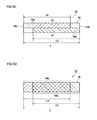
- the thickness Da of the upstream catalyst layer 18 a was set to 1 ⁇ 2 of the thickness D of the partition wall 16
- the thickness Db of the downstream catalyst layer 18 b was set to 1 ⁇ 2 of the thickness D of the partition wall 16 as illustrated in FIG. 5A
- the thicknesses Da, Db of the upstream catalyst layer 18 a and the downstream catalyst layer 18 b are not limited thereto.
- the upstream catalyst layer 18 a may be formed in a portion corresponding to a range of 50% to 100% of the thickness D of the partition wall 16 (preferably, a range of 50% to 80%, i.e.
- the downstream catalyst layer 18 b may be formed in a portion corresponding to a range of 50% to 100% of the thickness D of the partition wall 16 (preferably, a range of 50% to 80%, i.e. 1 ⁇ 2 to 4 ⁇ 5 of the thickness of the partition wall), from the surface of the partition wall 16 in contact with the outlet cells 14 towards the inlet cells 12 .
- the downstream catalyst layer 18 b may be formed so as not to overlap the upstream catalyst layer 18 a in the thickness direction of the partition wall 16 . As illustrated for instance in FIG.
- the upstream catalyst layer 18 a may be formed in such a manner that 80 mass % or more of the total amount of the SCR catalyst (SCR catalyst contained in the upstream catalyst layer 18 a ) is present in a portion corresponding to up to 80% of the thickness D of the partition wall 16 , from the surface of the partition wall 16 in contact with the inlet cells 12 towards the outlet cells 14 .
- the downstream catalyst layer 18 b may be formed in such a manner that 80 mass % or more of the total amount of the SCR catalyst (SCR catalyst contained in the downstream catalyst layer 18 b ) is present in a portion corresponding to up to 80% of the thickness D of the partition wall 16 , from the surface of the partition wall 16 in contact with the outlet cells 14 towards the inlet cells 12 . Enhancement of NOx purification performance and ammonia slip suppression can be achieved, at a yet higher level, within the above ranges of the thickness of the upstream catalyst layer 18 a and the downstream catalyst layer 18 b and of the distribution of the respective SCR catalyst therein.
- the length La of the upstream catalyst layer 18 a was set to 1 ⁇ 2 of the total length L of the filter 10
- the length Lb of the downstream catalyst layer 18 b was set to 1 ⁇ 2 of the total length L of the filter 10 .
- the lengths La, Lb of the upstream catalyst layer 18 a and the downstream catalyst layer 18 b are not limited thereto.
- the upstream catalyst layer 18 a may be formed in a portion corresponding to at least 20% of the total length L of the filter 10 (at most 80%, i.e.
- the downstream catalyst layer 18 b may be formed in a portion corresponding to at least 20% of the total length L of the filter 10 (at most 80%, i.e. within a range of 1 ⁇ 5 to 4 ⁇ 5 of the substrate as a whole), from the exhaust gas outlet-side (downstream end) of the filter 10 towards the exhaust gas inlet (upstream side).
- the upstream catalyst layer 18 a and the downstream catalyst layer 18 b are formed so as not to overlap.
- the formation pattern of the upstream catalyst layer 18 a and the downstream catalyst layer 18 b is not limited thereto.
- the upstream catalyst layer 18 a and the downstream catalyst layer 18 b may be formed overlapping each other (i.e. in such a manner that the SCR catalyst contained in the upstream catalyst layer 18 a and the SCR catalyst contained in the downstream catalyst layer 18 b coexist partially).
- La 0.2L to 0.8L
- Lb 0.2L to 0.8L
- L ⁇ La+Lb ⁇ 1.6L where L denotes the total length of the filter 10 , La denotes the length of the upstream catalyst layer 18 a and Lb denotes the length of the downstream portion 10 b .
- Enhancement of NOx purification performance and ammonia slip suppression can be achieved, at a yet higher level, within the above ranges of length La, Lb of the upstream catalyst layer 18 a and the downstream catalyst layer 18 b.
- test examples relating to the present invention will be explained next, but the present invention is not meant to be limited to the test examples illustrated below.
- SAPO having Cu supported thereon was prepared as the SCR catalyst.
- a slurry A was obtained by charging 200 g of the Cu-supporting SAPO into a solution resulting from mixing 350 g of pure water and 200 g of an Al 2 O 3 sol (AS200, by Nissan Chemical Industries Ltd.), and by stirring and milling the whole.
- ⁇ -zeolite having Fe supported thereon was prepared as an SCR catalyst.
- a slurry B was obtained by charging 200 g of the Fe-supporting ⁇ -zeolite into a solution resulting from mixing 350 g of pure water and 200 g of an Al 2 O 3 sol (AS200, by Nissan Chemical Industries Ltd.), and by stirring and milling the whole.
- the viscosity of the slurry A and the slurry B was adjusted through addition of an organic polymer to the slurries (polyvinyl alcohol having a molecular weight of about 5000 was used herein).
- the exhaust gas inflow end of a cordierite substrate (wall flow-type substrate illustrated in FIG. 2 to FIG. 4 : diameter 129 mm, total length 150 mm, volume 2000 cm 3 , average pore size 25 ⁇ m, porosity 60%) was wash-coated with 255 g of the slurry B.
- the slurry B was next caused to permeate, by air blowing, into the partition wall 16 (in a portion (see FIG.
- An elemental analysis of a cross-section of the obtained filter catalyst revealed that the total amount of the Fe-supporting ⁇ -zeolite was present in a portion (hereafter referred to as first stage) corresponding to 50% of the length L of the cordierite substrate, from the exhaust gas inflow end of the substrate towards the downstream side, being a portion corresponding to 50% of the thickness of the partition wall 16 from the surface of the partition wall 16 in contact with the inlet cells 12 towards the outlet cells 14 (see FIG. 5A ).
- the total amount of Cu-supporting SAPO was found to be present in a portion (hereafter referred to as second stage) corresponding to 50% of the length L of the cordierite substrate from the exhaust gas outflow end of the substrate towards the upstream side, being a portion corresponding to 50% of the thickness of the partition wall 16 from the surface of the partition wall 16 in contact with the outlet cells 14 towards the inlet cells 12 (see FIG. 5A ).
- the coating amount of the first stage and the second stage of the filter catalyst is 75 g per L of substrate.
- the addition amount of the organic polymer to the slurries was modified to make the viscosities of the slurry A and the slurry B different from those of Example 1.
- the degree of permeation of the wash coat layer in the thickness direction of the partition wall 16 was rendered different from that of Example 1 by modifying the air blowing conditions.
- the slurry B was caused to permeate over a portion corresponding to 50% of the length L of the cordierite substrate, from the exhaust gas inflow end of the substrate towards the downstream side, and being a portion corresponding to 80% of the thickness of the partition wall 16 , from the surface of the partition wall 16 in contact with the inlet cells 12 towards the outlet cells 14 (see FIG. 5B ).
- the slurry A was caused to permeate over a portion corresponding to 50% of the length L of the cordierite substrate, from the exhaust gas outflow end of the substrate towards the upstream side, and being a portion corresponding to 80% of the thickness of the partition wall 16 from the surface of the partition wall 16 in contact with the outlet cells 14 towards the inlet cells 12 (see FIG. 5B ).
- a filter catalyst was produced according to a procedure in which other conditions were identical to those of Example 1.
- An elemental analysis of a cross-section of the obtained filter catalyst revealed that 80% of the total amount of the Fe-supporting ⁇ -zeolite was present in a portion corresponding to 50% of the length L of the cordierite substrate, from the exhaust gas inflow end of the substrate towards the downstream side, being a portion corresponding to 80% of the thickness of the partition wall 16 from the surface of the partition wall 16 in contact with the inlet cells 12 towards the outlet cells 14 .
- 80% of the total amount of Cu-supporting SAPO was found to be present in a portion corresponding to 50% of the length L of the cordierite substrate from the exhaust gas outflow end of the substrate towards the upstream side, being a portion corresponding to 80% of the thickness of the partition wall 16 from the surface of the partition wall 16 in contact with the outlet cells 14 towards the inlet cells 12 .
- the addition amount of the organic polymer to the slurries was modified to make the viscosities of the slurry A and the slurry B different from those of Example 1.
- the degree of permeation of the wash coat layer in the thickness direction of the partition wall 16 was rendered different from that of Example 1 by modifying the air blowing conditions.
- the slurry B was caused to permeate over a portion corresponding to 80% of the length L of the cordierite substrate, from the exhaust gas inflow end of the substrate towards the downstream side, and being a portion corresponding to 50% of the thickness of the partition wall 16 , from the surface of the partition wall 16 in contact with the inlet cells 12 towards the outlet cells 14 (see FIG. 5C ).
- the slurry A was caused to permeate over a portion corresponding to 80% of the length L of the cordierite substrate, from the exhaust gas outflow end of the substrate towards the upstream side, and being a portion corresponding to 50% of the thickness of the partition wall 16 from the surface of the partition wall 16 in contact with the outlet cells 14 towards the inlet cells 12 (see FIG. 5C ).
- a filter catalyst was produced according to a procedure in which other conditions were identical to those of Example 1.
- the total amount of Cu-supporting SAPO was found to be present in a portion corresponding to 80% of the length L of the cordierite substrate from the exhaust gas outflow end of the substrate towards the upstream side, being a portion corresponding to 50% of the thickness of the partition wall 16 from the surface of the partition wall 16 in contact with the outlet cells 14 towards the inlet cells 12 .
- the addition amount of the organic polymer to the slurries was modified to make the viscosities of the slurry A and the slurry B different from those of Example 1.
- the degree of permeation of the wash coat layer in the thickness direction of the partition wall 16 was rendered different from that of Example 1 by modifying the air blowing conditions.
- the slurry B was caused to permeate over a portion corresponding to 80% of the length L of the cordierite substrate, from the exhaust gas inflow end of the substrate towards the downstream side, and being a portion corresponding to 80% of the thickness of the partition wall 16 , from the surface of the partition wall 16 in contact with the inlet cells 12 towards the outlet cells 14 (see FIG. 5D ).
- the slurry A was caused to permeate over a portion corresponding to 80% of the length L of the cordierite substrate, from the exhaust gas outflow end of the substrate towards the upstream side, and being a portion corresponding to 80% of the thickness of the partition wall 16 from the surface of the partition wall 16 in contact with the outlet cells 14 towards the inlet cells 12 (see FIG. 5D ).
- a filter catalyst was produced according to a procedure in which other conditions were identical to those of Example 1.
- An elemental analysis of a cross-section of the obtained filter catalyst revealed that 80% of the total amount of the Fe-supporting ⁇ -zeolite was present in a portion corresponding to 80% of the length L of the cordierite substrate, from the exhaust gas inflow end of the substrate towards the downstream side, being a portion corresponding to 80% of the thickness of the partition wall 16 from the surface of the partition wall 16 in contact with the inlet cells 12 towards the outlet cells 14 .
- 80% of the total amount of Cu-supporting SAPO was found to be present in a portion corresponding to 80% of the length L of the cordierite substrate from the exhaust gas outflow end of the substrate towards the upstream side, being a portion corresponding to 80% of the thickness of the partition wall 16 from the surface of the partition wall 16 in contact with the outlet cells 14 towards the inlet cells 12 .
- slurry A an identical material alone was used in both the upstream catalyst layer 18 a and the downstream catalyst layer 18 b , but the maximum allowable adsorption amount of ammonia was set to vary by using different wash coating amounts.
- the exhaust gas inflow end a cordierite substrate was wash-coated using 240 g of the slurry A.
- the slurry A was next caused to permeate, by air blowing, into the partition wall 16 (in a portion (see FIG.
- the total amount of second-stage Cu-supporting SAPO was found to be present in a portion corresponding to 50% of the length L of the cordierite substrate from the exhaust gas outflow end of the substrate towards the upstream side, being a portion corresponding to 50% of the thickness of the partition wall 16 from the surface of the partition wall 16 in contact with the outlet cells 14 towards the inlet cells 12 (see FIG. 5A ).
- the first-stage coating amount of the filter is 70 g per L of substrate
- the second-stage coating amount is 80 g per L of substrate.
- a filter catalyst was produced in accordance with the same procedure as that of Example 5, but herein the air blow conditions during wash coating were modified.
- An elemental analysis of a cross-section of the obtained filter catalyst revealed that 80% of the total amount of first-stage Cu-supporting SAPO was present in a portion corresponding to 50% of the length L of the cordierite substrate, from the exhaust gas inflow end of the substrate towards the downstream side, being a portion corresponding to 80% of the thickness of the partition wall 16 from the surface of the partition wall 16 in contact with the inlet cells 12 towards the outlet cells 14 (see FIG. 5B ).
- a filter catalyst was produced under conditions identical to those of Example 3, but herein the exhaust gas inflow end of the cordierite substrate was wash-coated using 242 g of the slurry A, and the exhaust gas outflow end of the substrate was wash-coated using 268 g of the slurry A.
- the total amount of the Cu-supporting SAPO contained in the slurry A with which the exhaust gas outflow end of the substrate cordierite was wash-coated was found to be present in a portion corresponding to 80% of the length L of the substrate from the exhaust gas outflow end of the substrate towards the upstream side, being a portion corresponding to 50% of the thickness of the partition wall 16 from the surface of the partition wall 16 in contact with the outlet cells 14 towards the inlet cells 12 (see FIG. 5C ).
- a filter catalyst was produced in accordance with the same procedure as that of Example 7, but herein the air blow conditions during wash coating were modified.
- An elemental analysis of a cross-section of the obtained filter catalyst revealed that 80% of the total amount of the Cu-supporting SAPO contained in the slurry A initially charged was present in a portion corresponding to 80% of the length L of the cordierite substrate, from the exhaust gas inflow end of the substrate towards the downstream side, being a portion corresponding to 80% of the thickness of the partition wall 16 from the surface of the partition wall 16 in contact with the inlet cells 12 towards the outlet cells 14 (see FIG. 5D ).
- 80% of the total amount of Cu-supporting SAPO contained in the slurry A charged the second time was found to be present in a portion corresponding to 80% of the length L of the cordierite substrate from the exhaust gas outflow end of the substrate towards the upstream side, being a portion corresponding to 80% of the thickness of the partition wall 16 from the surface of the partition wall 16 in contact with the outlet cells 14 towards the inlet cells 12 (see FIG. 5D ).
- a filter catalyst was produced by immersing a cordierite substrate in the slurry A and removing the excess slurry through air blowing, followed by drying and firing.
- a filter catalyst was produced by immersing a cordierite substrate in the slurry B and removing the excess slurry through air blowing, followed by drying and firing.
- a Cu-supporting SAPO and 100 g of a Fe-supporting (3-zeolite were charged into a solution resulting from mixing 350 g of pure water and 200 g of a SiO 2 sol (SNOWTEX S, by Nissan Chemical Industries Ltd.), with stirring and milling of the whole, to yield a slurry C.
- a filter catalyst was produced by immersing a cordierite substrate in the slurry C and removing the excess slurry through air blowing, followed by drying and firing.
- the NOx purification ability of the filter catalysts of the examples was evaluated. Specifically, the filter catalyst of each example having been subjected beforehand to hydrothermal aging at 650° C. for 50 hours was fitted to the exhaust pipe of a 2.2 L common-rail diesel engine; exhaust gas was caused to flow through the filter catalyst, and the NOx purification rate was measured. An oxidation catalyst was disposed in the exhaust pipe, upstream of the filter catalyst, in order to remove unburned diesel oil discharged by the engine. An injector was disposed in the exhaust pipe upstream of the filter catalyst, and aqueous urea, as a reducing agent solution for generating ammonia, was added from the injector.
- the aqueous urea was adjusted so that the equivalent ratio of NH 3 with respect to NOx was 0.5 or 1.
- the NOx purification rate (%) was calculated herein on the basis of “(NOx concentration (ppm) of gas entering the catalyst ⁇ NOx concentration (ppm) of gas leaving the catalyst)/NOx concentration (ppm) of gas entering the catalyst” ⁇ 100.
- the NH 3 concentration was measured downstream of the filter catalyst, and ammonia slip was evaluated under various conditions in conjunction with the NOx purification rate.
- the evaluation temperature was set to 450° C. The results are given in Table 1.
- the filter catalysts in Comparative examples 1 and 3 in which there was no difference in the maximum allowable adsorption amount of ammonia between the first stage and the second stage, exhibited low NOx purification rate and poor NOx purification performance, in a case where the NH 3 /NOx equivalent ratio was 0.5 (relatively little addition of aqueous urea).
- the filter catalyst of Comparative example 2 exhibited a higher NOx purification rate than those of Comparative examples 1 and 3, the NOx purification rate was lower than in other samples, and significant ammonia slip was likewise observed, when the NH 3 /NOx equivalent ratio was 1 (relatively large addition of aqueous urea).
- the exhaust gas purification device 100 is particularly suitable as a device for purification of harmful components in exhaust gas of comparatively low exhaust temperature, for instance in diesel engines.
- the exhaust gas purification device 100 according to the present invention is not limited to being used for purification of harmful components in exhaust gas of diesel engines, and can be used in various applications that involve purifying harmful components in exhaust gas emitted by other engines (for instance, gasoline engines).
- the present invention allows providing a high-performance exhaust gas purification material that combines NOx purification and ammonia emission suppression at a high level, the material being provided with a particulate filter that contains an SCR catalyst.
Landscapes
- Chemical & Material Sciences (AREA)
- Engineering & Computer Science (AREA)
- Chemical Kinetics & Catalysis (AREA)
- Combustion & Propulsion (AREA)
- Health & Medical Sciences (AREA)
- Organic Chemistry (AREA)
- Materials Engineering (AREA)
- Oil, Petroleum & Natural Gas (AREA)
- General Chemical & Material Sciences (AREA)
- Analytical Chemistry (AREA)
- Environmental & Geological Engineering (AREA)
- Biomedical Technology (AREA)
- Mechanical Engineering (AREA)
- General Engineering & Computer Science (AREA)
- Toxicology (AREA)
- Crystallography & Structural Chemistry (AREA)
- Exhaust Gas After Treatment (AREA)
- Processes For Solid Components From Exhaust (AREA)
- Exhaust Gas Treatment By Means Of Catalyst (AREA)
Priority Applications (1)
| Application Number | Priority Date | Filing Date | Title |
|---|---|---|---|
| US16/014,979 US10335736B2 (en) | 2013-12-11 | 2018-06-21 | Exhaust gas purification material |
Applications Claiming Priority (3)
| Application Number | Priority Date | Filing Date | Title |
|---|---|---|---|
| JP2013-255818 | 2013-12-11 | ||
| JP2013255818 | 2013-12-11 | ||
| PCT/JP2014/082319 WO2015087816A1 (ja) | 2013-12-11 | 2014-12-05 | 排ガス浄化材 |
Related Parent Applications (1)
| Application Number | Title | Priority Date | Filing Date |
|---|---|---|---|
| PCT/JP2014/082319 A-371-Of-International WO2015087816A1 (ja) | 2013-12-11 | 2014-12-05 | 排ガス浄化材 |
Related Child Applications (1)
| Application Number | Title | Priority Date | Filing Date |
|---|---|---|---|
| US16/014,979 Continuation-In-Part US10335736B2 (en) | 2013-12-11 | 2018-06-21 | Exhaust gas purification material |
Publications (2)
| Publication Number | Publication Date |
|---|---|
| US20160279571A1 US20160279571A1 (en) | 2016-09-29 |
| US10029209B2 true US10029209B2 (en) | 2018-07-24 |
Family
ID=53371121
Family Applications (1)
| Application Number | Title | Priority Date | Filing Date |
|---|---|---|---|
| US15/037,356 Active 2034-12-23 US10029209B2 (en) | 2013-12-11 | 2014-12-05 | Exhaust gas purification material |
Country Status (5)
| Country | Link |
|---|---|
| US (1) | US10029209B2 (zh) |
| EP (1) | EP3081777B2 (zh) |
| JP (1) | JP6532826B2 (zh) |
| CN (1) | CN105814292B (zh) |
| WO (1) | WO2015087816A1 (zh) |
Families Citing this family (16)
| Publication number | Priority date | Publication date | Assignee | Title |
|---|---|---|---|---|
| JP6294127B2 (ja) * | 2014-03-31 | 2018-03-14 | 株式会社キャタラー | Scr用触媒及び排ガス浄化触媒システム |
| EP3177386B1 (en) * | 2014-08-07 | 2019-11-27 | Johnson Matthey Public Limited Company | Zoned catalyst for treating exhaust gas |
| US10125649B2 (en) | 2014-10-16 | 2018-11-13 | Cataler Corporation | Exhaust gas purification catalyst |
| US10113462B2 (en) * | 2015-04-24 | 2018-10-30 | Cummins Inc. | Advanced exhaust aftertreatment system architecture |
| DE102017106374A1 (de) * | 2016-04-01 | 2017-10-05 | Johnson Matthey Public Limited Company | Abgasreinigungsfilter |
| JP6738185B2 (ja) | 2016-04-07 | 2020-08-12 | 株式会社キャタラー | 排ガス浄化装置 |
| JP7155108B2 (ja) * | 2016-08-05 | 2022-10-18 | ビーエーエスエフ コーポレーション | 選択的触媒還元物品およびシステム |
| JP6346642B2 (ja) * | 2016-09-26 | 2018-06-20 | 株式会社キャタラー | 排ガス浄化用触媒 |
| JP6605522B2 (ja) * | 2017-03-09 | 2019-11-13 | 株式会社キャタラー | 排ガス浄化用触媒 |
| GB2562161A (en) * | 2017-03-20 | 2018-11-07 | Johnson Matthey Plc | Rear on-wall design SCRF |
| JP6487982B1 (ja) * | 2017-09-28 | 2019-03-20 | 株式会社キャタラー | 排ガス浄化用触媒 |
| JP7174516B2 (ja) * | 2017-10-31 | 2022-11-17 | 株式会社キャタラー | 排ガス浄化用触媒 |
| WO2020031975A1 (ja) * | 2018-08-09 | 2020-02-13 | エヌ・イーケムキャット株式会社 | 触媒塗工ガソリンパティキュレートフィルター及びその製造方法 |
| KR102165633B1 (ko) * | 2019-04-05 | 2020-10-14 | 희성촉매 주식회사 | 배기가스 정화용 촉매 필터의 촉매 슬러리 정량 코팅 방법 |
| JP7414413B2 (ja) * | 2019-06-26 | 2024-01-16 | 株式会社キャタラー | パティキュレートフィルタ |
| JP6994079B2 (ja) * | 2020-05-26 | 2022-01-14 | 株式会社キャタラー | 排ガス浄化触媒装置 |
Citations (13)
| Publication number | Priority date | Publication date | Assignee | Title |
|---|---|---|---|---|
| JP2004060494A (ja) | 2002-07-26 | 2004-02-26 | Toyota Motor Corp | 内燃機関の排気浄化装置 |
| WO2005014146A1 (en) | 2003-08-05 | 2005-02-17 | Umicore Ag & Co. Kg | Catalyst arrangement and method of purifying the exhaust gas of internal combustion engines operated under lean conditions |
| DE102005005663A1 (de) | 2005-02-08 | 2006-08-17 | Daimlerchrysler Ag | Abgasnachbehandlungseinrichtung mit Partikelfilter |
| JP2006291873A (ja) | 2005-04-12 | 2006-10-26 | Toyota Motor Corp | 内燃機関の排気浄化装置 |
| JP2007185571A (ja) | 2006-01-11 | 2007-07-26 | Toyota Central Res & Dev Lab Inc | 排ガス浄化用触媒及びその製造方法 |
| US20090087365A1 (en) | 2007-09-27 | 2009-04-02 | Raoul Klingmann | Removal of particulates from the exhaust gas of internal combustion engines operated with a predominantly stoichiometric air/fuel mixture |
| WO2009124643A1 (de) | 2008-04-11 | 2009-10-15 | Umicore Ag & Co. Kg | Abgasreinigungssystem zur behandlung von motorenabgasen mittels scr-katalysator |
| US20100115930A1 (en) * | 2008-11-07 | 2010-05-13 | Gm Global Technology Operations, Inc. | Exhaust after treatment system |
| WO2011015615A1 (en) | 2009-08-05 | 2011-02-10 | Basf Se | Treatment system for gasoline engine exhaust gas |
| US20110052454A1 (en) | 2009-09-02 | 2011-03-03 | Kabushiki Kaisha Toyota Jidoshokki | Exhaust gas purification apparatus |
| WO2012166833A1 (en) | 2011-05-31 | 2012-12-06 | Johnson Matthey Public Limited Company | Dual function catalytic filter |
| US20130255229A1 (en) | 2012-03-30 | 2013-10-03 | Man Truck & Bus Ag | Method for use in conjunction with an exhaust-gas aftertreatment system |
| US20140301923A1 (en) * | 2013-03-14 | 2014-10-09 | Basf Corporation | Selective Catalytic Reduction Catalyst System |
Family Cites Families (11)
| Publication number | Priority date | Publication date | Assignee | Title |
|---|---|---|---|---|
| JP2002188435A (ja) * | 2000-10-12 | 2002-07-05 | Toyota Motor Corp | 排ガス浄化フィルタ |
| ATE464458T1 (de) * | 2007-02-23 | 2010-04-15 | Umicore Ag & Co Kg | Katalytisch aktiviertes dieselpartikelfilter mit ammoniak-sperrwirkung |
| WO2009118869A1 (ja) | 2008-03-27 | 2009-10-01 | イビデン株式会社 | ハニカム構造体および排ガス処理装置 |
| JP4729631B2 (ja) | 2009-03-11 | 2011-07-20 | トヨタ自動車株式会社 | 内燃機関の排気浄化装置 |
| EP2439384B1 (en) * | 2009-06-03 | 2017-04-05 | Toyota Jidosha Kabushiki Kaisha | Exhaust gas purification device for internal combustion engine |
| GB2475740B (en) * | 2009-11-30 | 2017-06-07 | Johnson Matthey Plc | Catalysts for treating transient NOx emissions |
| US9120056B2 (en) | 2010-02-16 | 2015-09-01 | Ford Global Technologies, Llc | Catalyst assembly for treating engine exhaust |
| JP5632195B2 (ja) * | 2010-05-17 | 2014-11-26 | 日野自動車株式会社 | 排気浄化装置 |
| JP5627367B2 (ja) | 2010-09-22 | 2014-11-19 | トヨタ自動車株式会社 | 排気浄化装置及び排気浄化装置の制御方法 |
| US8789356B2 (en) | 2011-07-28 | 2014-07-29 | Johnson Matthey Public Limited Company | Zoned catalytic filters for treatment of exhaust gas |
| DE102012005508A1 (de) * | 2012-03-17 | 2013-09-19 | Daimler Ag | Katalysatorbauteil einer Kraftfahrzeug-Abgasreinigungsanlage und Verwendung eines Katalysatorbauteils |
-
2014
- 2014-12-05 JP JP2015552429A patent/JP6532826B2/ja active Active
- 2014-12-05 WO PCT/JP2014/082319 patent/WO2015087816A1/ja active Application Filing
- 2014-12-05 EP EP14868881.5A patent/EP3081777B2/en active Active
- 2014-12-05 CN CN201480067269.XA patent/CN105814292B/zh active Active
- 2014-12-05 US US15/037,356 patent/US10029209B2/en active Active
Patent Citations (24)
| Publication number | Priority date | Publication date | Assignee | Title |
|---|---|---|---|---|
| JP2004060494A (ja) | 2002-07-26 | 2004-02-26 | Toyota Motor Corp | 内燃機関の排気浄化装置 |
| WO2005014146A1 (en) | 2003-08-05 | 2005-02-17 | Umicore Ag & Co. Kg | Catalyst arrangement and method of purifying the exhaust gas of internal combustion engines operated under lean conditions |
| JP2007501107A (ja) | 2003-08-05 | 2007-01-25 | ユミコア・アクチエンゲゼルシャフト・ウント・コムパニー・コマンディットゲゼルシャフト | 触媒装置およびリーン条件下で運転される内燃機関の排ガスを浄化する方法 |
| DE102005005663A1 (de) | 2005-02-08 | 2006-08-17 | Daimlerchrysler Ag | Abgasnachbehandlungseinrichtung mit Partikelfilter |
| JP2006291873A (ja) | 2005-04-12 | 2006-10-26 | Toyota Motor Corp | 内燃機関の排気浄化装置 |
| JP2007185571A (ja) | 2006-01-11 | 2007-07-26 | Toyota Central Res & Dev Lab Inc | 排ガス浄化用触媒及びその製造方法 |
| US20090087365A1 (en) | 2007-09-27 | 2009-04-02 | Raoul Klingmann | Removal of particulates from the exhaust gas of internal combustion engines operated with a predominantly stoichiometric air/fuel mixture |
| JP2009082915A (ja) | 2007-09-27 | 2009-04-23 | Umicore Ag & Co Kg | 主として化学量論的空気/燃料混合物により運転される内燃機関エンジンの排ガスからの粒子の除去 |
| WO2009124643A1 (de) | 2008-04-11 | 2009-10-15 | Umicore Ag & Co. Kg | Abgasreinigungssystem zur behandlung von motorenabgasen mittels scr-katalysator |
| JP2011518658A (ja) | 2008-04-11 | 2011-06-30 | ユミコア・アクチエンゲゼルシャフト・ウント・コムパニー・コマンディットゲゼルシャフト | Scr触媒によるエンジン排気ガスの処理のための排気ガス浄化システム |
| US20110146237A1 (en) | 2008-04-11 | 2011-06-23 | Umicore Ag & Co. Kg | Exhaust gas purification system for the treatment of engine exhaust gases by means of scr catalyst |
| US20100115930A1 (en) * | 2008-11-07 | 2010-05-13 | Gm Global Technology Operations, Inc. | Exhaust after treatment system |
| CN101732991A (zh) | 2008-11-07 | 2010-06-16 | 通用汽车环球科技运作公司 | 排气后处理系统 |
| US20110030346A1 (en) | 2009-08-05 | 2011-02-10 | Basf Se | Treatment System for Gasoline Engine Exhaust Gas |
| WO2011015615A1 (en) | 2009-08-05 | 2011-02-10 | Basf Se | Treatment system for gasoline engine exhaust gas |
| JP2013500857A (ja) | 2009-08-05 | 2013-01-10 | ビーエーエスエフ ソシエタス・ヨーロピア | ガソリンエンジン排ガス処理システム |
| EP2292904A2 (en) | 2009-09-02 | 2011-03-09 | Kabushiki Kaisha Toyota Jidoshokki | Exhaust gas purification apparatus |
| JP2011052612A (ja) | 2009-09-02 | 2011-03-17 | Toyota Industries Corp | 排気ガス浄化装置 |
| US20110052454A1 (en) | 2009-09-02 | 2011-03-03 | Kabushiki Kaisha Toyota Jidoshokki | Exhaust gas purification apparatus |
| WO2012166833A1 (en) | 2011-05-31 | 2012-12-06 | Johnson Matthey Public Limited Company | Dual function catalytic filter |
| JP2014522306A (ja) | 2011-05-31 | 2014-09-04 | ジョンソン、マッセイ、パブリック、リミテッド、カンパニー | 二元機能触媒フィルター |
| US20130255229A1 (en) | 2012-03-30 | 2013-10-03 | Man Truck & Bus Ag | Method for use in conjunction with an exhaust-gas aftertreatment system |
| CN103362610A (zh) | 2012-03-30 | 2013-10-23 | 曼卡车和巴士股份公司 | 与废气后处理装置结合的应用方法 |
| US20140301923A1 (en) * | 2013-03-14 | 2014-10-09 | Basf Corporation | Selective Catalytic Reduction Catalyst System |
Non-Patent Citations (3)
| Title |
|---|
| Feb. 10, 2015 International Search Report issued in International Patent Application No. PCT/JP2014/082319. |
| Jan. 12, 2018 Office Action issued in Chinese Patent Application No. 201480067269.X. |
| Jun. 23, 2016 International Preliminary Report on Patentability issued in International Patent Application No. PCT/JP2014/082319. |
Also Published As
| Publication number | Publication date |
|---|---|
| WO2015087816A1 (ja) | 2015-06-18 |
| CN105814292B (zh) | 2018-11-30 |
| EP3081777A1 (en) | 2016-10-19 |
| EP3081777A4 (en) | 2017-08-02 |
| JP6532826B2 (ja) | 2019-06-19 |
| CN105814292A (zh) | 2016-07-27 |
| EP3081777B2 (en) | 2022-09-28 |
| JPWO2015087816A1 (ja) | 2017-03-16 |
| US20160279571A1 (en) | 2016-09-29 |
| EP3081777B1 (en) | 2019-02-06 |
Similar Documents
| Publication | Publication Date | Title |
|---|---|---|
| US10029209B2 (en) | Exhaust gas purification material | |
| RU2392456C2 (ru) | Способ и устройство для очистки выхлопного газа | |
| US9981223B2 (en) | Exhaust gas purification apparatus | |
| US8544260B2 (en) | Emissions treatment systems and methods with catalyzed SCR filter and downstream SCR catalyst | |
| EP2382031B2 (en) | Emissions treatment systems and methods with catalyzed scr filter and downstream scr catalyst | |
| US8679412B2 (en) | Exhaust gas-purifying system | |
| WO2012132678A1 (ja) | アンモニア酸化触媒、およびそれを用いた排気ガス浄化装置並びに排気ガス浄化方法 | |
| KR101986388B1 (ko) | Egr 회로에서 암모니아 슬립 촉매를 가지는 배기 시스템 | |
| RU2015150059A (ru) | Двигатель с принудительным воспламенением топлива и выхлопной системой, содержащей катализируемую фильтрующую подложку с покрытыми зонами | |
| US10286392B2 (en) | Exhaust gas purification catalyst | |
| JP2013506787A (ja) | 4サイクルディーゼルに用いる触媒およびその使用方法 | |
| CN107849962B (zh) | 用于钝化选择性催化还原的催化烟灰过滤器及其制备方法 | |
| US9346019B2 (en) | Coated diesel particle filter | |
| JP2018528062A (ja) | 膜を有する触媒ウォールフロー型フィルター | |
| CN108568308B (zh) | 排气净化用催化剂 | |
| US10335736B2 (en) | Exhaust gas purification material | |
| JP2015112559A (ja) | パティキュレートフィルタ | |
| WO2018123286A1 (ja) | 排ガス浄化用触媒 | |
| WO2024029290A1 (ja) | 排ガス処理用システム | |
| JP7174516B2 (ja) | 排ガス浄化用触媒 | |
| KR20160056174A (ko) | 디젤매연필터의 촉매 코팅방법 | |
| CN117677761A (zh) | 用于净化汽油发动机的废气的废气系统 | |
| KR20170016445A (ko) | 배기가스 정화 장치 | |
| KR20160056173A (ko) | 디젤매연필터의 촉매 코팅방법 |
Legal Events
| Date | Code | Title | Description |
|---|---|---|---|
| AS | Assignment |
Owner name: CATALER CORPORATION, JAPAN Free format text: ASSIGNMENT OF ASSIGNORS INTEREST;ASSIGNORS:TSUJI, MAKOTO;IMAI, HIROTO;KOBAYASHI, SHINTARO;REEL/FRAME:038631/0163 Effective date: 20160121 |
|
| STCF | Information on status: patent grant |
Free format text: PATENTED CASE |
|
| MAFP | Maintenance fee payment |
Free format text: PAYMENT OF MAINTENANCE FEE, 4TH YEAR, LARGE ENTITY (ORIGINAL EVENT CODE: M1551); ENTITY STATUS OF PATENT OWNER: LARGE ENTITY Year of fee payment: 4 |