WO2024029290A1 - 排ガス処理用システム - Google Patents
排ガス処理用システム Download PDFInfo
- Publication number
- WO2024029290A1 WO2024029290A1 PCT/JP2023/025626 JP2023025626W WO2024029290A1 WO 2024029290 A1 WO2024029290 A1 WO 2024029290A1 JP 2023025626 W JP2023025626 W JP 2023025626W WO 2024029290 A1 WO2024029290 A1 WO 2024029290A1
- Authority
- WO
- WIPO (PCT)
- Prior art keywords
- catalyst
- exhaust gas
- region
- flow path
- gas flow
- Prior art date
Links
- 239000003054 catalyst Substances 0.000 claims abstract description 621
- 239000000969 carrier Substances 0.000 claims abstract description 20
- 238000011144 upstream manufacturing Methods 0.000 claims abstract description 18
- LSQZJLSUYDQPKJ-NJBDSQKTSA-N amoxicillin Chemical compound C1([C@@H](N)C(=O)N[C@H]2[C@H]3SC([C@@H](N3C2=O)C(O)=O)(C)C)=CC=C(O)C=C1 LSQZJLSUYDQPKJ-NJBDSQKTSA-N 0.000 claims abstract 9
- 239000010457 zeolite Substances 0.000 claims description 76
- 239000000463 material Substances 0.000 claims description 66
- 229910021536 Zeolite Inorganic materials 0.000 claims description 65
- HNPSIPDUKPIQMN-UHFFFAOYSA-N dioxosilane;oxo(oxoalumanyloxy)alumane Chemical compound O=[Si]=O.O=[Al]O[Al]=O HNPSIPDUKPIQMN-UHFFFAOYSA-N 0.000 claims description 65
- BASFCYQUMIYNBI-UHFFFAOYSA-N platinum Chemical group [Pt] BASFCYQUMIYNBI-UHFFFAOYSA-N 0.000 claims description 45
- 239000002245 particle Substances 0.000 claims description 41
- 230000007704 transition Effects 0.000 claims description 2
- 238000000746 purification Methods 0.000 abstract description 41
- 239000007789 gas Substances 0.000 description 178
- MWUXSHHQAYIFBG-UHFFFAOYSA-N nitrogen oxide Inorganic materials O=[N] MWUXSHHQAYIFBG-UHFFFAOYSA-N 0.000 description 90
- QGZKDVFQNNGYKY-UHFFFAOYSA-N Ammonia Chemical compound N QGZKDVFQNNGYKY-UHFFFAOYSA-N 0.000 description 61
- PNEYBMLMFCGWSK-UHFFFAOYSA-N aluminium oxide Inorganic materials [O-2].[O-2].[O-2].[Al+3].[Al+3] PNEYBMLMFCGWSK-UHFFFAOYSA-N 0.000 description 41
- MCMNRKCIXSYSNV-UHFFFAOYSA-N ZrO2 Inorganic materials O=[Zr]=O MCMNRKCIXSYSNV-UHFFFAOYSA-N 0.000 description 30
- 239000002585 base Substances 0.000 description 29
- GWEVSGVZZGPLCZ-UHFFFAOYSA-N Titan oxide Chemical compound O=[Ti]=O GWEVSGVZZGPLCZ-UHFFFAOYSA-N 0.000 description 28
- 239000002002 slurry Substances 0.000 description 27
- 238000000576 coating method Methods 0.000 description 25
- 239000002131 composite material Substances 0.000 description 24
- 230000003647 oxidation Effects 0.000 description 23
- 238000007254 oxidation reaction Methods 0.000 description 23
- VYPSYNLAJGMNEJ-UHFFFAOYSA-N Silicium dioxide Chemical compound O=[Si]=O VYPSYNLAJGMNEJ-UHFFFAOYSA-N 0.000 description 22
- 229910021529 ammonia Inorganic materials 0.000 description 22
- XEEYBQQBJWHFJM-UHFFFAOYSA-N Iron Chemical compound [Fe] XEEYBQQBJWHFJM-UHFFFAOYSA-N 0.000 description 21
- 239000004202 carbamide Substances 0.000 description 21
- 229910052751 metal Inorganic materials 0.000 description 21
- 239000002184 metal Substances 0.000 description 21
- XSQUKJJJFZCRTK-UHFFFAOYSA-N Urea Chemical compound NC(N)=O XSQUKJJJFZCRTK-UHFFFAOYSA-N 0.000 description 20
- 239000003638 chemical reducing agent Substances 0.000 description 20
- KDLHZDBZIXYQEI-UHFFFAOYSA-N palladium Substances [Pd] KDLHZDBZIXYQEI-UHFFFAOYSA-N 0.000 description 20
- 239000011248 coating agent Substances 0.000 description 18
- 230000003197 catalytic effect Effects 0.000 description 16
- 229910052723 transition metal Inorganic materials 0.000 description 16
- 239000011230 binding agent Substances 0.000 description 15
- 238000000034 method Methods 0.000 description 15
- 238000003860 storage Methods 0.000 description 15
- QVGXLLKOCUKJST-UHFFFAOYSA-N atomic oxygen Chemical compound [O] QVGXLLKOCUKJST-UHFFFAOYSA-N 0.000 description 14
- 239000001301 oxygen Substances 0.000 description 14
- 229910052760 oxygen Inorganic materials 0.000 description 14
- 239000010949 copper Substances 0.000 description 13
- 238000010438 heat treatment Methods 0.000 description 10
- 229910000510 noble metal Inorganic materials 0.000 description 10
- 229910052763 palladium Inorganic materials 0.000 description 9
- 229910052697 platinum Inorganic materials 0.000 description 9
- GQPLMRYTRLFLPF-UHFFFAOYSA-N Nitrous Oxide Chemical compound [O-][N+]#N GQPLMRYTRLFLPF-UHFFFAOYSA-N 0.000 description 8
- 229910052802 copper Inorganic materials 0.000 description 8
- 229910052742 iron Inorganic materials 0.000 description 8
- 229910000069 nitrogen hydride Inorganic materials 0.000 description 8
- 239000010948 rhodium Substances 0.000 description 8
- 239000000377 silicon dioxide Substances 0.000 description 8
- 229910018072 Al 2 O 3 Inorganic materials 0.000 description 7
- RYGMFSIKBFXOCR-UHFFFAOYSA-N Copper Chemical compound [Cu] RYGMFSIKBFXOCR-UHFFFAOYSA-N 0.000 description 7
- 229910004298 SiO 2 Inorganic materials 0.000 description 7
- CETPSERCERDGAM-UHFFFAOYSA-N ceric oxide Chemical compound O=[Ce]=O CETPSERCERDGAM-UHFFFAOYSA-N 0.000 description 7
- 229910000422 cerium(IV) oxide Inorganic materials 0.000 description 7
- 229910052878 cordierite Inorganic materials 0.000 description 7
- JSKIRARMQDRGJZ-UHFFFAOYSA-N dimagnesium dioxido-bis[(1-oxido-3-oxo-2,4,6,8,9-pentaoxa-1,3-disila-5,7-dialuminabicyclo[3.3.1]nonan-7-yl)oxy]silane Chemical compound [Mg++].[Mg++].[O-][Si]([O-])(O[Al]1O[Al]2O[Si](=O)O[Si]([O-])(O1)O2)O[Al]1O[Al]2O[Si](=O)O[Si]([O-])(O1)O2 JSKIRARMQDRGJZ-UHFFFAOYSA-N 0.000 description 7
- 229930195733 hydrocarbon Natural products 0.000 description 7
- 150000002430 hydrocarbons Chemical class 0.000 description 7
- 229910010272 inorganic material Inorganic materials 0.000 description 7
- XLYOFNOQVPJJNP-UHFFFAOYSA-N water Substances O XLYOFNOQVPJJNP-UHFFFAOYSA-N 0.000 description 7
- 229910000873 Beta-alumina solid electrolyte Inorganic materials 0.000 description 6
- UGFAIRIUMAVXCW-UHFFFAOYSA-N Carbon monoxide Chemical compound [O+]#[C-] UGFAIRIUMAVXCW-UHFFFAOYSA-N 0.000 description 6
- QPLDLSVMHZLSFG-UHFFFAOYSA-N Copper oxide Chemical compound [Cu]=O QPLDLSVMHZLSFG-UHFFFAOYSA-N 0.000 description 6
- UQSXHKLRYXJYBZ-UHFFFAOYSA-N Iron oxide Chemical compound [Fe]=O UQSXHKLRYXJYBZ-UHFFFAOYSA-N 0.000 description 6
- 229910010413 TiO 2 Inorganic materials 0.000 description 6
- 229910052784 alkaline earth metal Inorganic materials 0.000 description 6
- -1 ammonium ions Chemical class 0.000 description 6
- 239000012298 atmosphere Substances 0.000 description 6
- 229910002091 carbon monoxide Inorganic materials 0.000 description 6
- 238000002485 combustion reaction Methods 0.000 description 6
- 238000006073 displacement reaction Methods 0.000 description 6
- 238000005342 ion exchange Methods 0.000 description 6
- TWNQGVIAIRXVLR-UHFFFAOYSA-N oxo(oxoalumanyloxy)alumane Chemical compound O=[Al]O[Al]=O TWNQGVIAIRXVLR-UHFFFAOYSA-N 0.000 description 6
- RVTZCBVAJQQJTK-UHFFFAOYSA-N oxygen(2-);zirconium(4+) Chemical compound [O-2].[O-2].[Zr+4] RVTZCBVAJQQJTK-UHFFFAOYSA-N 0.000 description 6
- 239000013618 particulate matter Substances 0.000 description 6
- 239000000047 product Substances 0.000 description 6
- 229910052814 silicon oxide Inorganic materials 0.000 description 6
- QDZRBIRIPNZRSG-UHFFFAOYSA-N titanium nitrate Chemical compound [O-][N+](=O)O[Ti](O[N+]([O-])=O)(O[N+]([O-])=O)O[N+]([O-])=O QDZRBIRIPNZRSG-UHFFFAOYSA-N 0.000 description 6
- OGIDPMRJRNCKJF-UHFFFAOYSA-N titanium oxide Inorganic materials [Ti]=O OGIDPMRJRNCKJF-UHFFFAOYSA-N 0.000 description 6
- OERNJTNJEZOPIA-UHFFFAOYSA-N zirconium nitrate Chemical compound [Zr+4].[O-][N+]([O-])=O.[O-][N+]([O-])=O.[O-][N+]([O-])=O.[O-][N+]([O-])=O OERNJTNJEZOPIA-UHFFFAOYSA-N 0.000 description 6
- 229910001928 zirconium oxide Inorganic materials 0.000 description 6
- PXHVJJICTQNCMI-UHFFFAOYSA-N Nickel Chemical compound [Ni] PXHVJJICTQNCMI-UHFFFAOYSA-N 0.000 description 5
- 239000000654 additive Substances 0.000 description 5
- 230000033228 biological regulation Effects 0.000 description 5
- 230000000052 comparative effect Effects 0.000 description 5
- 150000001875 compounds Chemical class 0.000 description 5
- 238000009826 distribution Methods 0.000 description 5
- 238000001035 drying Methods 0.000 description 5
- 239000000203 mixture Substances 0.000 description 5
- 229910052703 rhodium Inorganic materials 0.000 description 5
- MHOVAHRLVXNVSD-UHFFFAOYSA-N rhodium atom Chemical compound [Rh] MHOVAHRLVXNVSD-UHFFFAOYSA-N 0.000 description 5
- 241000894007 species Species 0.000 description 5
- 239000007921 spray Substances 0.000 description 5
- 150000001768 cations Chemical class 0.000 description 4
- 229910000420 cerium oxide Inorganic materials 0.000 description 4
- 238000010586 diagram Methods 0.000 description 4
- 239000010931 gold Substances 0.000 description 4
- 230000009931 harmful effect Effects 0.000 description 4
- 239000011147 inorganic material Substances 0.000 description 4
- BMMGVYCKOGBVEV-UHFFFAOYSA-N oxo(oxoceriooxy)cerium Chemical compound [Ce]=O.O=[Ce]=O BMMGVYCKOGBVEV-UHFFFAOYSA-N 0.000 description 4
- 239000003973 paint Substances 0.000 description 4
- 239000011148 porous material Substances 0.000 description 4
- 239000010970 precious metal Substances 0.000 description 4
- 229910052761 rare earth metal Inorganic materials 0.000 description 4
- 229910001220 stainless steel Inorganic materials 0.000 description 4
- 239000010935 stainless steel Substances 0.000 description 4
- BNGXYYYYKUGPPF-UHFFFAOYSA-M (3-methylphenyl)methyl-triphenylphosphanium;chloride Chemical compound [Cl-].CC1=CC=CC(C[P+](C=2C=CC=CC=2)(C=2C=CC=CC=2)C=2C=CC=CC=2)=C1 BNGXYYYYKUGPPF-UHFFFAOYSA-M 0.000 description 3
- DUFCMRCMPHIFTR-UHFFFAOYSA-N 5-(dimethylsulfamoyl)-2-methylfuran-3-carboxylic acid Chemical compound CN(C)S(=O)(=O)C1=CC(C(O)=O)=C(C)O1 DUFCMRCMPHIFTR-UHFFFAOYSA-N 0.000 description 3
- KJTLSVCANCCWHF-UHFFFAOYSA-N Ruthenium Chemical compound [Ru] KJTLSVCANCCWHF-UHFFFAOYSA-N 0.000 description 3
- INNSZZHSFSFSGS-UHFFFAOYSA-N acetic acid;titanium Chemical compound [Ti].CC(O)=O.CC(O)=O.CC(O)=O.CC(O)=O INNSZZHSFSFSGS-UHFFFAOYSA-N 0.000 description 3
- HDYRYUINDGQKMC-UHFFFAOYSA-M acetyloxyaluminum;dihydrate Chemical compound O.O.CC(=O)O[Al] HDYRYUINDGQKMC-UHFFFAOYSA-M 0.000 description 3
- 239000002253 acid Substances 0.000 description 3
- 229940009827 aluminum acetate Drugs 0.000 description 3
- 239000003945 anionic surfactant Substances 0.000 description 3
- 229910001593 boehmite Inorganic materials 0.000 description 3
- 238000006243 chemical reaction Methods 0.000 description 3
- 230000001186 cumulative effect Effects 0.000 description 3
- 239000008367 deionised water Substances 0.000 description 3
- 229910021641 deionized water Inorganic materials 0.000 description 3
- 239000006185 dispersion Substances 0.000 description 3
- 230000000694 effects Effects 0.000 description 3
- 238000011156 evaluation Methods 0.000 description 3
- 239000010419 fine particle Substances 0.000 description 3
- 239000000446 fuel Substances 0.000 description 3
- FAHBNUUHRFUEAI-UHFFFAOYSA-M hydroxidooxidoaluminium Chemical compound O[Al]=O FAHBNUUHRFUEAI-UHFFFAOYSA-M 0.000 description 3
- 150000002484 inorganic compounds Chemical class 0.000 description 3
- 229910052741 iridium Inorganic materials 0.000 description 3
- GKOZUEZYRPOHIO-UHFFFAOYSA-N iridium atom Chemical compound [Ir] GKOZUEZYRPOHIO-UHFFFAOYSA-N 0.000 description 3
- 229910052746 lanthanum Inorganic materials 0.000 description 3
- FZLIPJUXYLNCLC-UHFFFAOYSA-N lanthanum atom Chemical compound [La] FZLIPJUXYLNCLC-UHFFFAOYSA-N 0.000 description 3
- 239000011572 manganese Substances 0.000 description 3
- 238000004519 manufacturing process Methods 0.000 description 3
- 239000002923 metal particle Substances 0.000 description 3
- 239000002736 nonionic surfactant Substances 0.000 description 3
- 239000003002 pH adjusting agent Substances 0.000 description 3
- 229910052707 ruthenium Inorganic materials 0.000 description 3
- 150000003839 salts Chemical class 0.000 description 3
- RMAQACBXLXPBSY-UHFFFAOYSA-N silicic acid Chemical compound O[Si](O)(O)O RMAQACBXLXPBSY-UHFFFAOYSA-N 0.000 description 3
- 239000006104 solid solution Substances 0.000 description 3
- 239000004071 soot Substances 0.000 description 3
- 239000003381 stabilizer Substances 0.000 description 3
- 239000004094 surface-active agent Substances 0.000 description 3
- 238000005979 thermal decomposition reaction Methods 0.000 description 3
- 229910052727 yttrium Inorganic materials 0.000 description 3
- VWQVUPCCIRVNHF-UHFFFAOYSA-N yttrium atom Chemical compound [Y] VWQVUPCCIRVNHF-UHFFFAOYSA-N 0.000 description 3
- IJGRMHOSHXDMSA-UHFFFAOYSA-N Atomic nitrogen Chemical compound N#N IJGRMHOSHXDMSA-UHFFFAOYSA-N 0.000 description 2
- 229920002134 Carboxymethyl cellulose Polymers 0.000 description 2
- PWHULOQIROXLJO-UHFFFAOYSA-N Manganese Chemical compound [Mn] PWHULOQIROXLJO-UHFFFAOYSA-N 0.000 description 2
- 239000002202 Polyethylene glycol Substances 0.000 description 2
- 229910052581 Si3N4 Inorganic materials 0.000 description 2
- BQCADISMDOOEFD-UHFFFAOYSA-N Silver Chemical compound [Ag] BQCADISMDOOEFD-UHFFFAOYSA-N 0.000 description 2
- 229910000831 Steel Inorganic materials 0.000 description 2
- CZMRCDWAGMRECN-UGDNZRGBSA-N Sucrose Chemical compound O[C@H]1[C@H](O)[C@@H](CO)O[C@@]1(CO)O[C@@H]1[C@H](O)[C@@H](O)[C@H](O)[C@@H](CO)O1 CZMRCDWAGMRECN-UGDNZRGBSA-N 0.000 description 2
- 229930006000 Sucrose Natural products 0.000 description 2
- 238000004458 analytical method Methods 0.000 description 2
- 230000015572 biosynthetic process Effects 0.000 description 2
- 229910052791 calcium Inorganic materials 0.000 description 2
- 239000001768 carboxy methyl cellulose Substances 0.000 description 2
- 235000010948 carboxy methyl cellulose Nutrition 0.000 description 2
- 239000008112 carboxymethyl-cellulose Substances 0.000 description 2
- 238000010531 catalytic reduction reaction Methods 0.000 description 2
- 239000000919 ceramic Substances 0.000 description 2
- 239000003426 co-catalyst Substances 0.000 description 2
- 229910017052 cobalt Inorganic materials 0.000 description 2
- 239000010941 cobalt Substances 0.000 description 2
- GUTLYIVDDKVIGB-UHFFFAOYSA-N cobalt atom Chemical compound [Co] GUTLYIVDDKVIGB-UHFFFAOYSA-N 0.000 description 2
- 230000001276 controlling effect Effects 0.000 description 2
- 230000006866 deterioration Effects 0.000 description 2
- 238000005485 electric heating Methods 0.000 description 2
- 150000004676 glycans Chemical class 0.000 description 2
- PCHJSUWPFVWCPO-UHFFFAOYSA-N gold Chemical compound [Au] PCHJSUWPFVWCPO-UHFFFAOYSA-N 0.000 description 2
- 229910052737 gold Inorganic materials 0.000 description 2
- 230000007062 hydrolysis Effects 0.000 description 2
- 238000001027 hydrothermal synthesis Methods 0.000 description 2
- 229920003063 hydroxymethyl cellulose Polymers 0.000 description 2
- 229940031574 hydroxymethyl cellulose Drugs 0.000 description 2
- 230000006872 improvement Effects 0.000 description 2
- 239000004615 ingredient Substances 0.000 description 2
- 239000011810 insulating material Substances 0.000 description 2
- 150000002500 ions Chemical class 0.000 description 2
- 229910052749 magnesium Inorganic materials 0.000 description 2
- 229910052748 manganese Inorganic materials 0.000 description 2
- 238000002156 mixing Methods 0.000 description 2
- 239000002808 molecular sieve Substances 0.000 description 2
- 229910052680 mordenite Inorganic materials 0.000 description 2
- 229910052759 nickel Inorganic materials 0.000 description 2
- 239000003921 oil Substances 0.000 description 2
- 230000001590 oxidative effect Effects 0.000 description 2
- 238000010422 painting Methods 0.000 description 2
- 230000002093 peripheral effect Effects 0.000 description 2
- 229920001223 polyethylene glycol Polymers 0.000 description 2
- 229920001282 polysaccharide Polymers 0.000 description 2
- 239000005017 polysaccharide Substances 0.000 description 2
- 230000009467 reduction Effects 0.000 description 2
- 238000006722 reduction reaction Methods 0.000 description 2
- HBMJWWWQQXIZIP-UHFFFAOYSA-N silicon carbide Chemical compound [Si+]#[C-] HBMJWWWQQXIZIP-UHFFFAOYSA-N 0.000 description 2
- 229910010271 silicon carbide Inorganic materials 0.000 description 2
- HQVNEWCFYHHQES-UHFFFAOYSA-N silicon nitride Chemical compound N12[Si]34N5[Si]62N3[Si]51N64 HQVNEWCFYHHQES-UHFFFAOYSA-N 0.000 description 2
- 229910052709 silver Inorganic materials 0.000 description 2
- 239000004332 silver Substances 0.000 description 2
- URGAHOPLAPQHLN-UHFFFAOYSA-N sodium aluminosilicate Chemical compound [Na+].[Al+3].[O-][Si]([O-])=O.[O-][Si]([O-])=O URGAHOPLAPQHLN-UHFFFAOYSA-N 0.000 description 2
- 239000010959 steel Substances 0.000 description 2
- 239000005720 sucrose Substances 0.000 description 2
- 239000002562 thickening agent Substances 0.000 description 2
- 150000003624 transition metals Chemical class 0.000 description 2
- 229910001868 water Inorganic materials 0.000 description 2
- VHUUQVKOLVNVRT-UHFFFAOYSA-N Ammonium hydroxide Chemical compound [NH4+].[OH-] VHUUQVKOLVNVRT-UHFFFAOYSA-N 0.000 description 1
- 241000269350 Anura Species 0.000 description 1
- 229910015999 BaAl Inorganic materials 0.000 description 1
- 229920003043 Cellulose fiber Polymers 0.000 description 1
- 239000005751 Copper oxide Substances 0.000 description 1
- 238000005033 Fourier transform infrared spectroscopy Methods 0.000 description 1
- 230000010718 Oxidation Activity Effects 0.000 description 1
- 238000002441 X-ray diffraction Methods 0.000 description 1
- 230000004913 activation Effects 0.000 description 1
- 229910052783 alkali metal Inorganic materials 0.000 description 1
- 150000001340 alkali metals Chemical class 0.000 description 1
- 150000001342 alkaline earth metals Chemical class 0.000 description 1
- 235000011114 ammonium hydroxide Nutrition 0.000 description 1
- 239000006227 byproduct Substances 0.000 description 1
- 150000004649 carbonic acid derivatives Chemical class 0.000 description 1
- NCEXYHBECQHGNR-UHFFFAOYSA-N chembl421 Chemical compound C1=C(O)C(C(=O)O)=CC(N=NC=2C=CC(=CC=2)S(=O)(=O)NC=2N=CC=CC=2)=C1 NCEXYHBECQHGNR-UHFFFAOYSA-N 0.000 description 1
- 239000011246 composite particle Substances 0.000 description 1
- 229910000431 copper oxide Inorganic materials 0.000 description 1
- 230000003247 decreasing effect Effects 0.000 description 1
- 230000005611 electricity Effects 0.000 description 1
- 238000005516 engineering process Methods 0.000 description 1
- 229910001657 ferrierite group Inorganic materials 0.000 description 1
- 239000005431 greenhouse gas Substances 0.000 description 1
- 238000006460 hydrolysis reaction Methods 0.000 description 1
- 238000002347 injection Methods 0.000 description 1
- 239000007924 injection Substances 0.000 description 1
- 238000009434 installation Methods 0.000 description 1
- 229910044991 metal oxide Inorganic materials 0.000 description 1
- 150000004706 metal oxides Chemical class 0.000 description 1
- 239000011490 mineral wool Substances 0.000 description 1
- 229910052757 nitrogen Inorganic materials 0.000 description 1
- 239000001272 nitrous oxide Substances 0.000 description 1
- 229910052762 osmium Inorganic materials 0.000 description 1
- SYQBFIAQOQZEGI-UHFFFAOYSA-N osmium atom Chemical compound [Os] SYQBFIAQOQZEGI-UHFFFAOYSA-N 0.000 description 1
- 230000000704 physical effect Effects 0.000 description 1
- 230000000607 poisoning effect Effects 0.000 description 1
- 239000000843 powder Substances 0.000 description 1
- 238000000634 powder X-ray diffraction Methods 0.000 description 1
- 238000002360 preparation method Methods 0.000 description 1
- 230000008569 process Effects 0.000 description 1
- 150000002910 rare earth metals Chemical class 0.000 description 1
- 230000001105 regulatory effect Effects 0.000 description 1
- 229910052702 rhenium Inorganic materials 0.000 description 1
- WUAPFZMCVAUBPE-UHFFFAOYSA-N rhenium atom Chemical compound [Re] WUAPFZMCVAUBPE-UHFFFAOYSA-N 0.000 description 1
- 238000005245 sintering Methods 0.000 description 1
- 239000011973 solid acid Substances 0.000 description 1
- 239000000243 solution Substances 0.000 description 1
- 150000003467 sulfuric acid derivatives Chemical class 0.000 description 1
- 230000001629 suppression Effects 0.000 description 1
- 238000010998 test method Methods 0.000 description 1
- 238000009283 thermal hydrolysis Methods 0.000 description 1
- WTHDKMILWLGDKL-UHFFFAOYSA-N urea;hydrate Chemical compound O.NC(N)=O WTHDKMILWLGDKL-UHFFFAOYSA-N 0.000 description 1
- 150000003672 ureas Chemical class 0.000 description 1
Images

Classifications
-
- B—PERFORMING OPERATIONS; TRANSPORTING
- B01—PHYSICAL OR CHEMICAL PROCESSES OR APPARATUS IN GENERAL
- B01D—SEPARATION
- B01D53/00—Separation of gases or vapours; Recovering vapours of volatile solvents from gases; Chemical or biological purification of waste gases, e.g. engine exhaust gases, smoke, fumes, flue gases, aerosols
- B01D53/34—Chemical or biological purification of waste gases
- B01D53/92—Chemical or biological purification of waste gases of engine exhaust gases
- B01D53/94—Chemical or biological purification of waste gases of engine exhaust gases by catalytic processes
-
- B—PERFORMING OPERATIONS; TRANSPORTING
- B01—PHYSICAL OR CHEMICAL PROCESSES OR APPARATUS IN GENERAL
- B01J—CHEMICAL OR PHYSICAL PROCESSES, e.g. CATALYSIS OR COLLOID CHEMISTRY; THEIR RELEVANT APPARATUS
- B01J29/00—Catalysts comprising molecular sieves
- B01J29/04—Catalysts comprising molecular sieves having base-exchange properties, e.g. crystalline zeolites
- B01J29/06—Crystalline aluminosilicate zeolites; Isomorphous compounds thereof
- B01J29/70—Crystalline aluminosilicate zeolites; Isomorphous compounds thereof of types characterised by their specific structure not provided for in groups B01J29/08 - B01J29/65
- B01J29/72—Crystalline aluminosilicate zeolites; Isomorphous compounds thereof of types characterised by their specific structure not provided for in groups B01J29/08 - B01J29/65 containing iron group metals, noble metals or copper
- B01J29/76—Iron group metals or copper
-
- F—MECHANICAL ENGINEERING; LIGHTING; HEATING; WEAPONS; BLASTING
- F01—MACHINES OR ENGINES IN GENERAL; ENGINE PLANTS IN GENERAL; STEAM ENGINES
- F01N—GAS-FLOW SILENCERS OR EXHAUST APPARATUS FOR MACHINES OR ENGINES IN GENERAL; GAS-FLOW SILENCERS OR EXHAUST APPARATUS FOR INTERNAL COMBUSTION ENGINES
- F01N3/00—Exhaust or silencing apparatus having means for purifying, rendering innocuous, or otherwise treating exhaust
- F01N3/02—Exhaust or silencing apparatus having means for purifying, rendering innocuous, or otherwise treating exhaust for cooling, or for removing solid constituents of, exhaust
- F01N3/021—Exhaust or silencing apparatus having means for purifying, rendering innocuous, or otherwise treating exhaust for cooling, or for removing solid constituents of, exhaust by means of filters
- F01N3/022—Exhaust or silencing apparatus having means for purifying, rendering innocuous, or otherwise treating exhaust for cooling, or for removing solid constituents of, exhaust by means of filters characterised by specially adapted filtering structure, e.g. honeycomb, mesh or fibrous
-
- F—MECHANICAL ENGINEERING; LIGHTING; HEATING; WEAPONS; BLASTING
- F01—MACHINES OR ENGINES IN GENERAL; ENGINE PLANTS IN GENERAL; STEAM ENGINES
- F01N—GAS-FLOW SILENCERS OR EXHAUST APPARATUS FOR MACHINES OR ENGINES IN GENERAL; GAS-FLOW SILENCERS OR EXHAUST APPARATUS FOR INTERNAL COMBUSTION ENGINES
- F01N3/00—Exhaust or silencing apparatus having means for purifying, rendering innocuous, or otherwise treating exhaust
- F01N3/02—Exhaust or silencing apparatus having means for purifying, rendering innocuous, or otherwise treating exhaust for cooling, or for removing solid constituents of, exhaust
- F01N3/021—Exhaust or silencing apparatus having means for purifying, rendering innocuous, or otherwise treating exhaust for cooling, or for removing solid constituents of, exhaust by means of filters
- F01N3/033—Exhaust or silencing apparatus having means for purifying, rendering innocuous, or otherwise treating exhaust for cooling, or for removing solid constituents of, exhaust by means of filters in combination with other devices
- F01N3/035—Exhaust or silencing apparatus having means for purifying, rendering innocuous, or otherwise treating exhaust for cooling, or for removing solid constituents of, exhaust by means of filters in combination with other devices with catalytic reactors, e.g. catalysed diesel particulate filters
-
- F—MECHANICAL ENGINEERING; LIGHTING; HEATING; WEAPONS; BLASTING
- F01—MACHINES OR ENGINES IN GENERAL; ENGINE PLANTS IN GENERAL; STEAM ENGINES
- F01N—GAS-FLOW SILENCERS OR EXHAUST APPARATUS FOR MACHINES OR ENGINES IN GENERAL; GAS-FLOW SILENCERS OR EXHAUST APPARATUS FOR INTERNAL COMBUSTION ENGINES
- F01N3/00—Exhaust or silencing apparatus having means for purifying, rendering innocuous, or otherwise treating exhaust
- F01N3/08—Exhaust or silencing apparatus having means for purifying, rendering innocuous, or otherwise treating exhaust for rendering innocuous
- F01N3/10—Exhaust or silencing apparatus having means for purifying, rendering innocuous, or otherwise treating exhaust for rendering innocuous by thermal or catalytic conversion of noxious components of exhaust
- F01N3/24—Exhaust or silencing apparatus having means for purifying, rendering innocuous, or otherwise treating exhaust for rendering innocuous by thermal or catalytic conversion of noxious components of exhaust characterised by constructional aspects of converting apparatus
- F01N3/28—Construction of catalytic reactors
Definitions
- the present disclosure relates to an exhaust gas treatment system including a selective catalytic reduction catalyst.
- DOC diesel oxidation catalysts
- HC hydrocarbons
- NOx nitrogen oxides
- DPF diesel particulate filter
- a catalyst slurry is coated on the DPF and a catalyst slurry is applied on the DPF, and a catalyst slurry is coated on the DPF and a catalyst layer is formed on the DPF.
- Catalyst-coated DPFs in which a catalyst layer is provided have also been proposed.
- urea SCR Selective Catalytic Reduction
- This urea SCR system employs an SCR catalyst that adsorbs ammonia produced by hydrolysis of urea.
- SCR catalyst used in a urea SCR system for example, zeolite on which transition metals such as iron and copper are supported (transition metal supported zeolite) is used in the urea SCR system because it is easy to obtain relatively high NOx purification performance. Widely used in systems.
- NOx is purified into nitrogen and water by chemically reacting NOx with ammonia on such an SCR catalyst.
- NOx is finally reduced to N 2 mainly by reaction formulas [1] to [3] shown below. 4NO+4NH 3 +O 2 ⁇ 4N 2 +6H 2 O ... [1] 6NO 2 +8NH 3 ⁇ 7N 2 +12H 2 O ... [2] NO+NO 2 +2NH 3 ⁇ 2N 2 +3H 2 O ... [3]
- N 2 O may be produced as a byproduct of the urea SCR reaction described above.
- Patent Document 1 includes an iron-supported zeolite in which iron is supported on a medium-pore or large-pore molecular sieve such as a zeolite having a BEA-type skeleton structure.
- Patent Document 2 describes a base material and an SCR catalyst layer on the base material.
- An exhaust gas purification catalyst device comprising: the base material includes catalytic noble metal particles directly supported on the base material; the catalytic noble metal particles contain Pt and Pd; and the average particle diameter of the catalytic noble metal particles is is from 30 nm to 120 nm, and the SCR catalyst layer includes a zeolite doped with Cu or Fe.
- Patent Document 1 and Patent Document 2 cannot be said to be practically sufficient.
- an object of the present disclosure is to provide an exhaust gas treatment system and the like that can achieve improved NOx and N 2 O purification performance.
- the present inventors have made extensive studies to solve the above problems. As a result, we discovered that the above problems can be solved by arranging a predetermined SCR catalyst and AMOX catalyst (Ammonia Oxidation Catalyst) upstream of the DOC catalyst and CSF catalyst, and we have completed the exhaust gas treatment system of the present disclosure. It's arrived.
- AMOX catalyst Ammonia Oxidation Catalyst
- An exhaust gas treatment system comprising a catalyst disposed in an exhaust gas flow path to purify exhaust gas passing through the exhaust gas flow path, the system comprising: one or more catalyst carriers; and one or more catalyst carriers provided on the catalyst carrier.
- the catalyst region includes a first SCR catalyst region disposed upstream of the exhaust gas flow path and having a catalyst length Ls in the flow direction of the exhaust gas flow path; a first AMOX catalyst region having a catalyst length La in the flow direction of the exhaust gas flow path, the first AMOX catalyst region being disposed on the downstream side of the exhaust gas flow path than the SCR catalyst region;
- An exhaust gas treatment system in which a catalyst length La satisfies the following formula (1) and the following formula (2). 0.30*(Ls+La) ⁇ Ls ⁇ 0.90*(Ls+La)...(1) 0.10*(Ls+La) ⁇ La ⁇ 0.70*(Ls+La)...(2)
- the catalyst carrier has a first catalyst carrier, and the first SCR catalyst region and the first AMOX catalyst region are provided on the first catalyst carrier.
- the catalyst carrier has a first catalyst carrier and a second catalyst carrier, the first SCR catalyst region is provided on the first catalyst carrier, and the first AMOX catalyst region is provided on the second catalyst carrier, the exhaust gas treatment system according to ⁇ 1> or ⁇ 2>.
- the length of the first catalyst carrier in the exhaust gas flow direction is within a range of 1.0 to 1.2*Ls with respect to the catalyst length Ls
- the catalyst region includes a DOC catalyst region located downstream of the exhaust gas flow path from the first AMOX catalyst region, and a DOC catalyst region located downstream of the exhaust gas flow path from the DOC catalyst region.
- the exhaust gas treatment system according to any one of ⁇ 1> to ⁇ 5>, further comprising a CSF catalyst region.
- the catalyst region includes a DOC catalyst region located downstream of the exhaust gas flow path from the first AMOX catalyst region, and a DOC catalyst region located downstream of the exhaust gas flow path from the DOC catalyst region. a CSF catalyst region, a second SCR catalyst region disposed downstream of the exhaust gas flow path from the DOC catalyst region and the CSF catalyst region, and a second SCR catalyst region located downstream of the exhaust gas flow path from the second SCR catalyst region.
- the exhaust gas treatment system according to any one of ⁇ 1> to ⁇ 5>, further comprising a second AMOX catalyst region disposed on the side.
- ⁇ 8> The exhaust gas treatment system according to any one of ⁇ 1> to ⁇ 7>, wherein the exhaust gas flow path is an exhaust gas flow path of a diesel engine.
- the first AMOX catalyst region has a laminated structure including a lower catalyst layer and an upper catalyst layer, and the lower catalyst layer includes base material particles and Pt supported on the base material particles.
- the exhaust gas treatment system according to any one of ⁇ 1> to ⁇ 8>, wherein the upper catalyst layer contains at least zeolite.
- the upper catalyst layer contains one or more transition metal-supported zeolites selected from the group consisting of Cu-supported zeolite and Fe-supported zeolite.
- FIG. 1 is a schematic diagram showing an exhaust gas treatment system 100 according to one aspect of the embodiment.
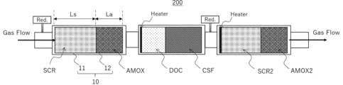
- FIG. 2 is a schematic diagram showing an exhaust gas treatment system 200 according to another aspect of the embodiment.
- the “average particle diameter D50” refers to the particle diameter when the cumulative value from small particle diameters reaches 50% of the total in the volume-based cumulative distribution of particle diameters, and is the so-called particle diameter.
- Median diameter means a value measured with a laser diffraction particle size distribution measuring device (for example, laser diffraction particle size distribution measuring device SALD-3100 manufactured by Shimadzu Corporation).
- the “average particle diameter D 90” refers to the particle diameter when the integrated value from small particle diameters reaches 90% of the total in the volume-based cumulative distribution of particle diameters.
- BET specific surface area refers to a specific surface area/pore distribution measuring device (product name: BELSORP-mini II, manufactured by Microtrack Bell Co., Ltd.) and analysis software (product name: BEL_Master, micro (manufactured by Track Bell Co., Ltd.), and is the value determined by the BET single point method.
- FIG. 1 is a schematic diagram showing an exhaust gas treatment system 100 of this embodiment.
- the exhaust gas treatment system 100 of this embodiment includes a catalyst that is disposed in an exhaust gas flow path (Gas Flow) and purifies the exhaust gas that passes through the exhaust gas flow path.
- This exhaust gas treatment system 100 includes one or more catalyst carriers 10 (catalyst carriers 11, 12) and a plurality of catalyst regions provided on the catalyst carrier 10, and the catalyst regions are arranged upstream of the exhaust gas flow path.
- the exhaust gas flow path also includes at least a first AMOX catalyst region (AMOX) having a catalyst length La in the flow path direction of the exhaust gas flow path.
- AMOX AMOX catalyst region
- the exhaust gas treatment system 100 of this embodiment is preferably used, for example, for purifying exhaust gas discharged from a lean burn engine such as a diesel engine.
- this exhaust gas treatment system 100 includes reducing agent supply means Red. further comprising this reducing agent supply means Red.
- Ammonia if the reducing agent is a urea component, ammonia generated by thermal decomposition of the urea component
- Ammonia resulting from the reducing agent supplied from the SCR catalyst region is adsorbed in the first SCR catalyst region, and the ammonia and NOx are brought into contact with each other. At the same time, excess ammonia is oxidized in the first AMOX catalyst region.
- the catalyst carrier 10 for example, a honeycomb structure widely used in automobile exhaust gas applications is preferably used.
- honeycomb structures include ceramic monolith carriers such as cordierite, silicon carbide, and silicon nitride, metal honeycomb carriers made of stainless steel, wire mesh carriers made of stainless steel, and steel wool-like knit wire carriers.
- the shape is not particularly limited, and any shape such as a prismatic shape, a cylindrical shape, a spherical shape, a honeycomb shape, a sheet shape, etc. can be selected. These can be used alone or in an appropriate combination of two or more.
- Honeycomb structures for automobile exhaust gas applications include flow-through type honeycomb structures in which gas channels are connected, and gas channels in which a portion of the end face is sealed and gas can flow through the wall surface of the gas channel.
- a wall flow type honeycomb structure is widely known, and any of these can be applied. Note that from the viewpoint of suppressing an excessive increase in pressure loss, a flow-through type honeycomb structure is preferably used.
- the catalyst carrier 10 A first SCR catalyst region is provided on the catalyst carrier 11, and a first AMOX catalyst region is provided on the catalyst carrier 12.
- the first SCR catalyst region means a region in which a catalyst material is provided on the catalyst carrier 11 in the flow direction of exhaust gas (the length direction of each catalyst carrier 11).
- the first AMOX catalyst region means a region in which a catalyst material is provided on the catalyst carrier 12 in the flow direction of exhaust gas (the length direction of each catalyst carrier 12). Therefore, the catalyst region provided on the catalyst carrier 10 can be understood as a set of two catalyst regions (the first SCR catalyst region and the first AMOX catalyst region).
- the total length of the catalyst region provided on the catalyst carrier 10 can be understood as the sum of the catalyst length Ls of the first SCR catalyst region and the catalyst length La of the first AMOX catalyst region in the exhaust gas flow direction.
- the capacity (size) of the catalyst carrier 10 (catalyst carriers 11, 12) and the amount of each catalyst material supported should be determined by taking into consideration the type and displacement of the lean-burn engine to be applied, and the amount of catalyst required. It can be adjusted as appropriate depending on the amount, purification performance, etc., and is not particularly limited.
- diesel engines range from small cars with a displacement of about 1L to heavy-duty diesel engines with a displacement of over 50L, and NOx and N2 are contained in the exhaust gas emitted from these diesel engines. O varies greatly depending on its operating state and combustion control method.
- the exhaust gas treatment system 100 of this embodiment which is used to purify NOx and N2O in the exhaust gas emitted from these lean-burn engines, can also be applied to a variety of diesel engine displacements from about 1L to over 50L. You can choose according to your gender. For example, by increasing or decreasing the diameter and length of the catalyst carrier used, the type and blending ratio of the catalyst material used, the amount supported in each catalyst region (first SCR catalyst region and first AMOX catalyst region), etc. , can be adjusted as appropriate.
- a catalyst material containing at least zeolite is used as the catalyst material constituting the first SCR catalyst region (hereinafter sometimes referred to as "zeolite-based catalyst material").
- zeolite-based catalyst material various zeolites conventionally used in this type of exhaust gas purification catalyst can be used without particular limitation.
- Specific examples of zeolite include Y type, A type, L type, mordenite type, ZSM-5 type, ferrierite type, mordenite type, CHA type, AEI type, AFX type, KFI type, SFW type, MFI type.
- zeolites as well as crystalline metal aluminophosphates such as SAPO and ALPO, but are not particularly limited thereto.
- These zeolites can be used alone or in any combination and ratio of two or more.
- Many zeolites of various grades are commercially available from domestic and foreign manufacturers, and commercially available products of various grades can be used depending on the required performance. Moreover, it can also be manufactured by a method known in the art.
- the skeletal structure of zeolite is compiled into a database by the International Zeolite Association (hereinafter sometimes abbreviated as "IZA"), and its IUPAC structural code (hereinafter also simply referred to as "structural code”) ) is referred to.
- IZA International Zeolite Association
- structural code hereinafter also simply referred to as "structural code”
- XRD powder X-ray diffraction
- the Si/Al ratio of the zeolite used is preferably from 1 to 500, more preferably from 1 to 100, even more preferably from 1 to 50.
- the average particle diameter D50 of the zeolite can be appropriately set depending on the desired performance and is not particularly limited. From the viewpoint of maintaining a large specific surface area, increasing heat resistance, and increasing the number of its own catalytic active sites, the average particle diameter D 50 of zeolite is preferably 0.5 ⁇ m to 100 ⁇ m, and preferably 0.5 ⁇ m to 50 ⁇ m. The thickness is more preferably 0.5 ⁇ m to 30 ⁇ m.
- the BET specific surface area of the zeolite can be set as appropriate depending on the desired performance, and is not particularly limited, but from the viewpoint of maintaining a large specific surface area and increasing the catalytic activity, the BET specific surface area by the BET single point method is It is preferably 10 m 2 /g to 1000 m 2 /g, more preferably 50 m 2 /g to 1000 m 2 /g, even more preferably 100 m 2 /g to 1000 m 2 /g.
- cations exist as counter ions in zeolites as solid acid sites, and the cations are generally ammonium ions and protons.
- the zeolite it is preferable to use the zeolite as a transition metal element ion-exchanged zeolite in which the cation sites of this zeolite are ion-exchanged with these transition metal elements.
- the transition metal element may be dispersed and held in the zeolite, but is preferably supported on the surface of the zeolite. Examples of transition metal elements include nickel (Ni), cobalt (Co), copper (Cu), iron (Fe), manganese (Mn), rhenium (Re), etc., but are not particularly limited thereto.
- the ion exchange rate of the zeolite is preferably 1% to 100%, more preferably 10% to 95%, even more preferably 30% to 90%. Note that when the ion exchange rate is 100%, it means that all the cation species in the zeolite have been ion-exchanged with transition metal element ions. Further, the amount of the transition metal element added to the zeolite is preferably 0.1% by mass to 10% by mass, more preferably 1% to 10% by mass, and 2% by mass in terms of oxide (CuO or Fe 2 O 3 ).
- the transition metal elements added as ion-exchange species may be ion-exchanged, but some of them may be present in the form of oxides such as copper oxide and iron oxide.
- the first SCR catalyst region uses CHA type, AEI type, AFX type, KFI type, SFW type, MFI type, It is preferable to contain at least an iron- and/or copper-supported zeolite containing a zeolite having a skeleton structure selected from the group consisting of and BEA type, and iron and/or copper supported on the zeolite.
- zeolites having a skeleton structure of one or more types selected from the group consisting of CHA, AEI, AFX, and AFT are preferred.
- iron and/or copper-supported zeolite containing iron and/or copper supported on the zeolite is more preferred.
- the amount supported in the first SCR catalyst region can be appropriately set depending on the desired performance, and is not particularly limited, but from the viewpoint of catalyst performance and balance of pressure loss, etc.
- the amount is preferably 10 g/L to 500 g/L, more preferably 20 g/L to 400 g/L, and even more preferably 30 g/L to 300 g/L.
- the amount of Fe added to the zeolite is preferably 0.1% by mass to 10% by mass, and 1.0% by mass to 8.0% by mass in terms of oxide (Fe 2 O 3 ). % is more preferable, and 1.5% to 7.0% by weight is even more preferable.
- the amount of Cu added to the zeolite is preferably 0.1% by mass to 10% by mass in terms of oxide (CuO), more preferably 1.0% by mass to 8.0% by mass. It is preferably 1.5% by mass to 7.0% by mass, more preferably 1.5% by mass to 7.0% by mass.
- CuO oxide
- all of the transition metal elements added as ion-exchange species may be ion-exchanged, or a part of them may exist in the form of an oxide such as iron oxide.
- the formation range of the first SCR catalyst region is not particularly limited, but it may be formed over the entire length of the catalyst carrier 11 in the flow direction of exhaust gas, or may be formed only in a part of the catalyst carrier 11. good.
- the length (total length) of the catalyst carrier 11 in the direction of the exhaust gas flow path is within the range of 1.0 to 1.2*Ls relative to the catalyst length Ls. It is preferably within the range of 1.0 to 1.1*Ls, and more preferably within the range of 1.0 to 1.1*Ls.
- the first SCR catalyst region may be formed offset on the upstream side of the catalyst carrier 11 in the flow direction of exhaust gas. Alternatively, it may be formed offset on the downstream side of the catalyst carrier 11.
- the first SCR catalyst region not only has excellent oxygen storage capacity but also relatively excellent heat resistance, as long as the effect of the exhaust gas treatment system of the present disclosure is not excessively inhibited. It may also contain oxygen storage/release materials such as ceria-based oxides and ceria-zirconia-based composite oxides, and other base material particles conventionally used in this type of exhaust gas purification catalyst.
- base particles include inorganic compounds known in the art, such as aluminum oxide (alumina: Al 2 O 3 ) such as ⁇ -alumina, ⁇ -alumina, ⁇ -alumina, ⁇ -alumina, and ⁇ -alumina; Examples include oxides such as zirconium oxide (zirconia: ZrO 2 ), silicon oxide (silica: SiO 2 ), titanium oxide (titania: TiO 2 ), and composite oxides based on these oxides. The type is not particularly limited. These may be composite oxides or solid solutions to which rare earth elements such as lanthanum and yttrium, transition metal elements, and alkaline earth metal elements are added. Note that these oxygen storage/release materials and other base material particles can be used singly or in any combination and ratio of two or more.
- aluminum oxide alumina: Al 2 O 3
- oxides such as zirconium oxide (zirconia: ZrO 2 ), silicon oxide (silica: SiO 2 ), titanium oxide (titania: TiO 2 ), and composite oxide
- the first SCR catalyst region may also contain various other catalyst materials, co-catalysts, and various additives known in the art.
- various sols such as boehmite, alumina sol, titania sol, silica sol, and zirconia sol; binders such as soluble salts such as aluminum nitrate, aluminum acetate, titanium nitrate, titanium acetate, zirconium nitrate, and zirconium acetate may be included. good.
- the first SCR catalyst region may further contain a Ba-containing compound in addition to the above-mentioned components.
- the first SCR catalyst region may contain a dispersion stabilizer such as a nonionic surfactant or anionic surfactant; a pH adjuster; a viscosity adjuster, and the like.
- a dispersion stabilizer such as a nonionic surfactant or anionic surfactant
- a pH adjuster such as sodium bicarbonate
- a viscosity adjuster such as sodium bicarbonate
- the thickener is not particularly limited, and examples thereof include polysaccharides such as sucrose, polyethylene glycol, carboxymethyl cellulose, and hydroxymethyl cellulose.
- the first SCR catalyst region contains alkaline earth metal elements such as Ca and Mg, as well as catalytic active components such as rhodium (Rh), ruthenium (Ru), palladium (Pd), platinum (Pt), and iridium (Ir). ), and noble metal elements such as gold (Au) and silver (Ag).
- alkaline earth metal elements such as Ca and Mg
- catalytic active components such as rhodium (Rh), ruthenium (Ru), palladium (Pd), platinum (Pt), and iridium (Ir).
- noble metal elements such as gold (Au) and silver (Ag).
- the platinum group elements and noble metal elements can be used singly or in any combination and ratio of two or more. However, since platinum group elements and noble metal elements oxidize the ammonia component and generate NOx, it is preferable that they are substantially not included.
- the content of platinum group elements and noble metal elements in the first SCR catalyst region is preferably less than 3 g/L, more preferably less than 1 g/L, in terms of metal amount per 1 L of catalyst carrier 11. It is more preferably less than 0.5 g/L, particularly preferably less than 0.001 g/L.
- the first SCR catalyst region may be placed directly on the catalyst carrier 11, or may be provided via a binder layer, a base layer, or the like.
- binder layers, underlayers, etc. those known in the art can be used, and their types are not particularly limited.
- oxygen storage/release materials such as cerium oxide (ceria: CeO 2 ), ceria-zirconia composite oxide (CZ composite oxide), ⁇ -alumina, ⁇ -alumina, ⁇ -alumina, ⁇ -alumina, ⁇ - Oxides such as aluminum oxide (alumina: Al 2 O 3 ) such as alumina, zirconium oxide (zirconia: ZrO 3 ), silicon oxide (silica: SiO 2 ), titanium oxide (titania: TiO 2 ), and their oxides Composite oxides containing as a main component, etc. can be used.
- the coating amount of the binder layer, base layer, etc. is not particularly limited, but is preferably 1 g/L to 150 g/L, more preferably 10 g/L to 100 g/L, per 1 L of catalyst carrier 11.
- a first AMOX catalyst region is provided on the catalyst carrier 12 located downstream of the exhaust gas flow path of the catalyst carrier 11 (first SCR catalyst region).
- This first AMOX catalyst region is connected to the reducing agent supply means Red.
- the excess ammonia that has passed through the first SCR catalyst region is removed. Oxidize.
- any catalyst material known in the art as a catalyst material for oxidizing ammonia can be used, and its type is not particularly limited.
- AMOX Ammonia oxidation catalyst
- an ammonia oxidation catalyst AMOX is additionally used downstream of the exhaust gas flow path of the SCR catalyst.
- Such an ammonia oxidation catalyst AMOX includes not only a catalyst having an NH 3 oxidation function but also a catalyst component having a NOx purification function.
- platinum group elements selected from platinum, palladium, rhodium, etc. are used as noble metal components, and an inorganic material (base material particle) consisting of one or more types of alumina, silica, titania, zirconia, etc. ) is widely known. It is also known to use inorganic materials whose heat resistance has been improved by adding promoters such as rare earth metals, alkali metals, and alkaline earth metals. On the other hand, platinum and palladium as platinum group elements exhibit excellent oxidation activity.
- ammonia oxidation catalyst AMOX are determined in consideration of the type and displacement of the engine to which the exhaust gas treatment system 100 of this embodiment is applied, and also the required amount of catalyst, purification performance, etc. It can be adjusted as appropriate and is not particularly limited.
- the first AMOX catalyst region used in this embodiment has a laminated structure including a lower catalyst layer and an upper catalyst layer, and the lower catalyst layer preferably includes base particles and a platinum group element supported on the base particles, and the upper catalyst layer preferably includes at least zeolite.
- the zeolite contained in the upper catalyst layer is preferably a zeolite having a skeleton structure selected from the group consisting of CHA, AEI, AFX, KFI, SFW, MFI, and BEA.
- the above-mentioned transition metal element ion exchange zeolite is more preferable, and the above-mentioned Cu-supported zeolite and Fe-supported zeolite are even more preferable.
- the lower catalyst layer is a composite material in which one or more platinum group elements selected from platinum, palladium, rhodium, etc. are supported on an inorganic material (base material particle) consisting of one or more types of alumina, silica, titania, zirconia, etc.
- a catalyst is used.
- the capacity (size) of the first AMOX catalyst region, the coating amount of the catalyst material, etc. are determined by taking into account the type and displacement of the engine to which the exhaust gas treatment system 100 of this embodiment is applied, and depending on the requirements. It can be adjusted as appropriate depending on the amount of catalyst used, purification performance, etc., and is not particularly limited.
- the amount supported on the lower catalyst layer of the first AMOX catalyst region can be appropriately set depending on the desired performance, and is not particularly limited.
- the amount of platinum group element metal per liter is preferably from 0.01 g/L to 5.0 g/L, more preferably from 0.02 g/L to 3.0 g/L, and from 0.03 g/L to 1.0 g. /L is more preferable.
- the supported amount of the upper catalyst layer in the first AMOX catalyst region is preferably 10 g/L to 500 g/L or less, more preferably 20 g/L to 400 g/L, in terms of zeolite per 1 L of the catalyst carrier 12. More preferably 30 g/L to 300 g/L.
- the amount of Fe added to the zeolite is preferably 0.1% by mass to 10% by mass in terms of oxide (Fe 2 O 3 ), and 1.0% by mass. It is more preferably 8.0% by weight, and even more preferably 1.5% by weight to 7.0% by weight.
- the amount of Cu added to the zeolite is preferably 0.1% by mass to 10% by mass, and 1.0% by mass to 8.0% by mass in terms of oxide (CuO). It is more preferably 1.5% by mass to 7.0% by mass.
- all of the transition metal elements added as ion-exchange species may be ion-exchanged, or a part of them may exist in the form of an oxide such as iron oxide.
- the formation range of the first AMOX catalyst region is not particularly limited, but it may be formed over the entire length of the catalyst carrier 12 in the flow direction of exhaust gas, or may be formed only in a part of the catalyst carrier 12. good.
- the length (total length) of the catalyst carrier 12 in the direction of the exhaust gas flow path is within the range of 1.0 to 1.2*La with respect to the catalyst length La. It is preferably within the range of 1.0 to 1.1*La, and more preferably within the range of 1.0 to 1.1*La.
- the first AMOX catalyst region when the first AMOX catalyst region is formed only in a part of the catalyst carrier 12, the first AMOX catalyst region may be formed offset on the upstream side of the catalyst carrier 12 in the flow direction of exhaust gas. Alternatively, it may be formed offset on the downstream side of the catalyst carrier 12.
- the first AMOX catalyst region not only has excellent oxygen storage capacity but also relatively excellent heat resistance, as long as the effect of the exhaust gas treatment system of the present disclosure is not excessively inhibited. It may also contain oxygen storage/release materials such as ceria-based oxides and ceria-zirconia-based composite oxides, and other base material particles conventionally used in this type of exhaust gas purification catalyst.
- base particles include inorganic compounds known in the art, such as aluminum oxide (alumina: Al 2 O 3 ) such as ⁇ -alumina, ⁇ -alumina, ⁇ -alumina, ⁇ -alumina, and ⁇ -alumina; Examples include oxides such as zirconium oxide (zirconia: ZrO 2 ), silicon oxide (silica: SiO 2 ), titanium oxide (titania: TiO 2 ), and composite oxides based on these oxides. The type is not particularly limited. These may be composite oxides or solid solutions to which rare earth elements such as lanthanum and yttrium, transition metal elements, and alkaline earth metal elements are added. Note that these oxygen storage/release materials and other base material particles can be used singly or in any combination and ratio of two or more.
- aluminum oxide alumina: Al 2 O 3
- oxides such as zirconium oxide (zirconia: ZrO 2 ), silicon oxide (silica: SiO 2 ), titanium oxide (titania: TiO 2 ), and composite oxide
- the first AMOX catalyst region may contain various other catalyst materials, promoters, and various additives known in the art.
- various sols such as boehmite, alumina sol, titania sol, silica sol, and zirconia sol; binders such as soluble salts such as aluminum nitrate, aluminum acetate, titanium nitrate, titanium acetate, zirconium nitrate, and zirconium acetate may be included. good.
- the first AMOX catalyst region may further contain a Ba-containing compound in addition to the above-mentioned components.
- the first AMOX catalyst region may contain a dispersion stabilizer such as a nonionic surfactant or anionic surfactant; a pH adjuster; a viscosity adjuster, and the like.
- a dispersion stabilizer such as a nonionic surfactant or anionic surfactant
- a pH adjuster such as a pH adjuster
- a viscosity adjuster such as a viscosity adjuster, and the like.
- the thickener is not particularly limited, and examples thereof include polysaccharides such as sucrose, polyethylene glycol, carboxymethyl cellulose, and hydroxymethyl cellulose.
- the first AMOX catalyst region contains alkaline earth metal elements such as Ca and Mg, as well as rhodium (Rh), ruthenium (Ru), palladium (Pd), platinum (Pt), and iridium (Ir) as catalyst active components. ), and noble metal elements such as gold (Au) and silver (Ag).
- alkaline earth metal elements such as Ca and Mg, as well as rhodium (Rh), ruthenium (Ru), palladium (Pd), platinum (Pt), and iridium (Ir) as catalyst active components.
- noble metal elements such as gold (Au) and silver (Ag).
- the platinum group elements and noble metal elements can be used singly or in any combination and ratio of two or more.
- the first AMOX catalyst region may be placed directly on the catalyst carrier 12, or may be provided via a binder layer, a base layer, or the like.
- binder layers, underlayers, etc. those known in the art can be used, and their types are not particularly limited.
- oxygen storage/release materials such as cerium oxide (ceria: CeO 2 ), ceria-zirconia composite oxide (CZ composite oxide), ⁇ -alumina, ⁇ -alumina, ⁇ -alumina, ⁇ -alumina, ⁇ - Oxides such as aluminum oxide (alumina: Al 2 O 3 ) such as alumina, zirconium oxide (zirconia: ZrO 3 ), silicon oxide (silica: SiO 2 ), titanium oxide (titania: TiO 2 ), and their oxides Composite oxides containing as a main component, etc. can be used.
- the coating amount of the binder layer, base layer, etc. is not particularly limited, but is preferably 1 g/L to 150 g/L, more preferably 10 g/L to 100 g/L, per 1 L of the catalyst carrier 12.
- the catalyst length Ls of the first SCR catalyst region and the catalyst length La of the first AMOX catalyst region described above are expressed by the following formula (1) and the following formula (2). ) is preferably satisfied.
- the exhaust gas treatment system 100 configured in this manner suppresses the generation of NOx caused by NH3 slip and the generation of N2O caused by oxidation of NH3 , and suppresses the generation of NOx and N2O . Purification performance is further improved. 0.30*(Ls+La) ⁇ Ls ⁇ 0.90*(Ls+La)...(1) 0.10*(Ls+La) ⁇ La ⁇ 0.70*(Ls+La)...(2)
- the catalyst length Ls of the first SCR catalyst region and the catalyst length La of the first AMOX catalyst region satisfy the following formula (1a) and the following formula (2a). 0.36*(Ls+La) ⁇ Ls ⁇ 0.86*(Ls+La)...(1a) 0.14*(Ls+La) ⁇ La ⁇ 0.64*(Ls+La)...(2a)
- the catalyst length Ls of the first SCR catalyst region and the catalyst length La of the first AMOX catalyst region satisfy the following formula (1b) and the following formula (2b). 0.30*(Ls+La) ⁇ Ls ⁇ 0.64*(Ls+La)...(1b) 0.36*(Ls+La) ⁇ La ⁇ 0.70*(Ls+La)...(2b)
- the first SCR catalyst region and the first AMOX catalyst region were provided separately on the two catalyst carriers 11 and 12, but the first SCR catalyst region
- the first SCR catalyst region and the first AMOX catalyst region are zone-coated on one catalyst carrier 11 in a predetermined ratio as long as they are arranged upstream of the exhaust gas flow path with respect to the first AMOX catalyst region.
- It can also be implemented as a zone coat SCR/AMOX.
- the zone coat is not particularly limited as long as the surface of one catalyst carrier is coated with multiple catalyst layers divided into sections, but for example, the zone coat As such, it is known to paint the central part and the outer peripheral part concentrically, or to paint the honeycomb structure differently in the depth direction of the through holes.
- zone coats varies depending on the composition, flow rate, temperature, etc. of the harmful components to be purified, and the optimum combination is set as appropriate.
- the ingredients are applied thinly.
- zone coating when a honeycomb structure is coated with catalyst components in multiple layers, one layer may be coated with a thick lower layer and a thin upper layer, and the other layer may be coated with a thin lower layer and a thick upper layer.
- the types of catalysts that can be painted differently include changing the combination of oxidation catalyst and reduction catalyst, and even for the same type of catalyst, the composition, concentration of active species, amount of coating on the honeycomb structure, etc. may be changed. .
- the installation locations of the first SCR catalyst region and the first AMOX catalyst region described above are as long as the first SCR catalyst region is arranged on the upstream side of the exhaust gas flow path with respect to the first AMOX catalyst region.
- it is preferably located directly below the exhaust system, that is, in the case of a lean burn engine such as a diesel engine, directly below the engine.
- a position directly below the engine means a position near the downstream side of the exhaust gas flow path with respect to the engine, and into which exhaust gas from the engine flows without passing through another catalyst.
- the first SCR catalyst region and the first AMOX catalyst region are provided directly below the engine, which means that there is another space between the engine and the first SCR catalyst region and the first AMOX catalyst region. means an embodiment in which no catalyst is involved.
- the reducing agent supply means Red. is for supplying one or more reducing agents selected from the group consisting of a urea component and an ammonia component into the exhaust gas flow path.
- Reducing agent supply means Red Those known in the art can be used, and the type thereof is not particularly limited.
- a tank is used that consists of a reducing agent storage tank, piping connected to the tank, and a spray nozzle attached to the tip of the piping (not shown).
- Reducing agent supply means Red The spray nozzle is installed upstream of the first SCR catalyst region described above.
- the above-mentioned catalyst regions first SCR catalyst region, first AMOX catalyst region
- reducing agent supply means Red it is preferable that the spray nozzle is arranged. Note that when other SCRs other than the first SCR catalyst region are used in combination and these are arranged apart from each other, the reducing agent supply means Red.
- the spray nozzles may be provided at multiple locations.
- the reducing component is selected from urea components and ammonia components.
- urea component a standardized aqueous urea solution with a concentration of 31.8% by mass to 33.3% by mass, such as the product name Adblue, can be used, and if it is an ammonia component, in addition to ammonia water, ammonia Gas etc. can also be used.
- NH3 which is a reducing component, has harmful effects such as a pungent odor in itself, so rather than using NH3 as a reducing component, it is preferable to add urea water from the upstream side of the exhaust gas treatment system 100.
- NH 3 is generated by thermal decomposition or hydrolysis, and this is used as a reducing agent.
- the exhaust gas treatment system 100 of the present embodiment includes a DOC catalyst region (DOC) arranged downstream of the first AMOX catalyst region in the exhaust gas flow path, and a DOC catalyst region (DOC) located downstream of the DOC catalyst region in the exhaust gas flow path. and a laterally disposed CSF catalytic region (CSF). That is, this exhaust gas treatment system 100 is disposed in an exhaust gas flow path and treats at least one type selected from the group consisting of CO, HC, NO, and NH3 in exhaust gas discharged from a lean burn engine such as a diesel engine.
- DOC DOC catalyst region
- DOC DOC catalyst region located downstream of the DOC catalyst region in the exhaust gas flow path.
- CSF CSF catalytic region
- the exhaust gas includes at least one DOC catalyst region that oxidizes PM, and a CSF catalyst region that is disposed in the exhaust gas flow path and that collects and burns or oxidizes and removes particulate component PM in the exhaust gas.
- a plasma generator Pl. etc. may be provided. Each component will be explained in detail below.
- the DOC catalyst region is a catalyst that is disposed in the exhaust gas flow path and oxidizes at least one selected from the group consisting of CO, HC, NO, and NH3 in the exhaust gas discharged from a lean burn engine such as a diesel engine.
- the DOC catalyst region refers to a diesel oxidation catalyst (DOC: Lean NOx storage catalyst (LNT: Diesel Oxidation Catalyst), which stores NOx under lean conditions and releases NOx under rich conditions, oxidizes CO and HC to CO2 and H2O , and reduces NOx to N2 .
- DOC Lean NOx storage catalyst
- LNT Diesel Oxidation Catalyst
- This concept includes Lean NOx Trap) and catalyst-coated PF (cPF) in which these are coated on PF.
- the DOC catalyst region of the exhaust gas treatment system 100 includes base material particles such as metal oxides such as alumina, zirconia, and ceria and zeolite, and platinum group elements (PGM) as catalyst active components supported on this carrier. Composite particles with metal) are commonly used. Various types of these oxidation catalysts are known in the art, and these various oxidation catalysts can be used alone or in any combination as appropriate for the DOC catalyst region.
- base material particles such as metal oxides such as alumina, zirconia, and ceria and zeolite, and platinum group elements (PGM) as catalyst active components supported on this carrier. Composite particles with metal) are commonly used.
- PGM platinum group elements
- the DOC catalyst region is a catalyst layer containing base material particles of inorganic fine particles and a platinum group element-supported catalyst material in which a platinum group element is supported on the base material particles on an integrally structured catalyst carrier such as a honeycomb structure. Those provided with this are preferably used.
- inorganic compounds conventionally used in this type of exhaust gas purification catalyst can be considered.
- oxygen storage/release materials such as zeolite, cerium oxide (ceria: CeO 2 ), ceria-zirconia composite oxide (CZ composite oxide), ⁇ -alumina, ⁇ -alumina, ⁇ -alumina, ⁇ -alumina , aluminum oxide (alumina: Al 2 O 3 ) such as ⁇ -alumina, zirconium oxide (zirconia: ZrO 2 ), silicon oxide (silica: SiO 2 ), titanium oxide (titania: TiO 2 ), and their oxides.
- OSC oxygen storage/release materials
- zeolite such as zeolite, cerium oxide (ceria: CeO 2 ), ceria-zirconia composite oxide (CZ composite oxide), ⁇ -alumina, ⁇ -alumina, ⁇ -alumina, ⁇ -alumina , aluminum oxide (alumina: Al 2 O 3 ) such as ⁇ -alumina, zirconium oxide (zi
- Examples include composite oxides containing oxides as a main component, but the type thereof is not particularly limited. Moreover, these may be composite oxides or solid solutions to which rare earth elements such as lanthanum and yttrium, transition metal elements, and alkaline earth metal elements are added. These inorganic fine particles can be used alone or in any combination and ratio of two or more.
- the oxygen storage/release material means a material that stores or releases oxygen depending on the external environment.
- the average particle diameter D50 of the base material particles in the DOC catalyst region can be appropriately set according to desired performance and is not particularly limited. From the viewpoint of maintaining a large specific surface area, increasing heat resistance, and increasing the number of its own catalytic active sites, the average particle diameter D 50 of the base material particles is preferably 0.5 ⁇ m to 100 ⁇ m, and 1 ⁇ m to 100 ⁇ m. The thickness is more preferably 1 ⁇ m to 50 ⁇ m.
- the BET specific surface area of the base material particles can be appropriately set depending on the desired performance, and is not particularly limited, but from the viewpoint of maintaining a large specific surface area and increasing the catalytic activity,
- the surface area is preferably 10 m 2 /g to 500 m 2 /g, more preferably 20 m 2 /g to 300 m 2 /g, even more preferably 30 m 2 /g to 200 m 2 /g.
- Many materials of various grades are commercially available from domestic and foreign manufacturers, and various grades of commercially available materials can be used as the base particles depending on the required performance. Moreover, it can also be manufactured by a method known in the art.
- platinum group elements examples include platinum (Pt), palladium (Pd), rhodium (Rh), ruthenium (Ru), iridium (Ir), and osmium (Os).
- the platinum group elements can be used alone or in any combination and ratio of two or more. From the viewpoint of improving exhaust gas purification performance and suppressing the progress of grain growth (sintering) of platinum group elements on base material particles, the content ratio of platinum group elements in the DOC catalyst area (per liter of monolithic catalyst carrier)
- the platinum group element mass is usually preferably 0.1 g/L to 20 g/L, more preferably 0.2 g/L to 15 g/L, even more preferably 0.3 g/L to 10 g/L. be.
- the DOC catalyst region may contain various other catalyst materials, promoters, and various additives known in the art.
- various sols such as boehmite, alumina sol, titania sol, silica sol, and zirconia sol; binders such as soluble salts such as aluminum nitrate, aluminum acetate, titanium nitrate, titanium acetate, zirconium nitrate, and zirconium acetate may be included.
- the DOC catalyst region may further contain a Ba-containing compound in addition to the above-mentioned components. By blending a Ba-containing compound, improvement in heat resistance and activation of catalyst performance can be expected.
- the Ba-containing compound examples include sulfates, carbonates, composite oxides, oxides, etc., but are not particularly limited thereto. More specifically, BaO, Ba(CH 3 COO) 2 , BaO 2 , BaSO 4 , BaCO 3 , BaZrO 3 , BaAl 2 O 4 and the like can be mentioned. Furthermore, the DOC catalyst region may contain a dispersion stabilizer such as a nonionic surfactant or anionic surfactant; a pH adjuster; a viscosity adjuster, and the like.
- a dispersion stabilizer such as a nonionic surfactant or anionic surfactant
- honeycomb structure widely used in automobile exhaust gas applications is preferably used.
- honeycomb structures include ceramic monolith carriers such as cordierite, silicon carbide, and silicon nitride, metal honeycomb carriers made of stainless steel, wire mesh carriers made of stainless steel, and steel wool-like knit wire carriers.
- shape is not particularly limited, and any shape such as a prismatic shape, a cylindrical shape, a spherical shape, a honeycomb shape, a sheet shape, etc. can be selected. These can be used alone or in an appropriate combination of two or more.
- Honeycomb structures for automotive exhaust gas applications include two types: a flow-through type structure in which the gas flow path is connected, and a flow-through structure in which a portion of the end face of the gas flow path is sealed and gas can flow through the wall surface of the gas flow path.
- a wall flow type structure is widely known, and any of these can be applied.
- the total coverage of the above-mentioned catalyst layer is not particularly limited, but from the viewpoint of catalyst performance and pressure drop balance, etc., it is 1 g/L to 500 g/L per liter of monolithic catalyst carrier. It is preferably 2 g/L to 450 g/L, more preferably 2 g/L to 80 g/L in the case of a wall-flow type catalyst carrier, and even more preferably 50 g/L to 300 g/L in the case of a flow-through type catalyst carrier.
- the DOC catalyst region may be placed directly on the monolithic catalyst carrier, or may be provided on the monolithic catalyst carrier via a binder layer, a base layer, or the like.
- a binder layer a base layer, or the like.
- the binder layer, base layer, etc. those known in the art can be used, and the types thereof are not particularly limited.
- oxygen storage/release materials such as zeolite, cerium oxide (ceria: CeO 2 ), ceria-zirconia composite oxide (CZ composite oxide), ⁇ -alumina, ⁇ -alumina, ⁇ -alumina, ⁇ -alumina , aluminum oxide (alumina: Al 2 O 3 ) such as ⁇ -alumina, zirconium oxide (zirconia: ZrO 2 ), silicon oxide (silica: SiO 2 ), titanium oxide (titania: TiO 2 ), and their oxides.
- a composite oxide containing an oxide as a main component can be used.
- the coating amount of the binder layer, base layer, etc. is not particularly limited, but is preferably 1 g/L to 150 g/L, more preferably 10 g/L to 100 g/L, per 1 L of the monolithic catalyst carrier.
- each DOC catalyst region is provided in the exhaust gas flow path of the exhaust gas treatment system 100, but a plurality (for example, 2 to 5) may be provided depending on the required performance, etc. You can.
- each DOC catalyst region may be the same type of oxidation catalyst or may be a different type of oxidation catalyst. It is also possible to use a zone-coated oxidation catalyst zDOC obtained by zone-coating two types of oxidation catalyst materials on one catalyst carrier.
- the zone coat is not particularly limited as long as the surface of one catalyst carrier is coated with multiple catalyst layers divided into sections, but for example, the zone coat As such, it is known to paint the central part and the outer peripheral part concentrically, or to paint the honeycomb structure differently in the depth direction of the through holes.
- the application of zone coats varies depending on the composition, flow rate, temperature, etc. of the harmful components to be purified, and the optimum combination is set as appropriate. For example, in the purification of automobile exhaust gas, when painting the front stage and the rear stage separately, one coats one with more types of catalyst components and the other with fewer types of catalyst components, and one coats with more precious metal components and the other with precious metals. There are cases where the ingredients are applied thinly.
- one layer may be coated with a thick lower layer and a thin upper layer, and the other layer may be coated with a thin lower layer and a thick upper layer.
- the types of catalysts that can be painted differently include changing the combination of oxidation catalyst and reduction catalyst, and even for the same type of catalyst, the composition, concentration of active species, amount of coating on the honeycomb structure, etc. may be changed. .
- each DOC catalyst region may be arranged adjacent to each other, and the CSF catalyst region and the reducing agent supply means Red. , heating device Heater, plasma generator Pl. They may be spaced apart from each other in the exhaust gas flow path.
- a CSF catalyst region is provided downstream of the DOC catalyst region described above.
- a catalyzed combustion filter CSF: Catalyzed Soot Filter
- This CSF catalyst region traps particulate components (PM) such as soot in the exhaust gas discharged from the lean fuel engine, and periodically sprays unburned light oil as necessary to burn or oxidize them and remove them.
- PM particulate components
- Such CSF catalyst regions are widely known in the art as particulate filters PF, catalyst-coated particulate filters cPF, catalyst-coated diesel particulate filters cDPF, and the like.
- an electric heating device Heater (catalyst heating heater) is provided in the exhaust gas flow path downstream of the first AMOX catalyst region and upstream of the DOC catalyst region. It is being This heating device is electrically connected to an ECU and an on-vehicle power source (not shown), and by controlling the output of these devices, the temperature of the heating device Heater and, by extension, the temperature of the exhaust gas in the exhaust gas flow path can be controlled.
- the catalytic performance of the DOC catalytic region can be promoted by heating the DOC catalytic region with a heater on the upstream side of the DOC catalytic region at the time of a cold start.
- the exhaust gas flow path is provided with temperature sensors, NOx sensors, etc. electrically connected to the ECU at various locations, and the NOx concentration and exhaust gas temperature of the exhaust gas are monitored at any time.
- the heating device Heater is composed of a metal honeycomb, a jacket-type electric heater attached to the outer periphery of the metal honeycomb, and a coil-type electric heater attached so as to be partially buried inside the metal honeycomb body. (not shown).
- This metal honeycomb can be electrically heated under the control of the control unit ECU, and the temperature of the exhaust gas passing through the exhaust gas flow path can be controlled by the heat generated by the metal honeycomb.
- a heat insulating material is provided on the outer periphery of the exhaust gas flow path over the entire length (not shown).
- the heat insulating material can be appropriately selected from those known in the art and is not particularly limited, but for example, materials using cellulose fibers, rock wool, etc. are preferably used.
- the heating device Heater used here may be, for example, only a jacket type electric heater, or may be an EHC (Electrically Heated Catalyst) in which an SCR catalyst is supported on a metal honeycomb body. Further, the metal honeycomb can also be heated by directly generating heat in the metal honeycomb itself by supplying electricity to the metal honeycomb body. In this case, the temperature of the metal honeycomb and, by extension, the temperature of the exhaust gas in the exhaust gas flow path can be controlled by connecting the metal honeycomb to an on-vehicle power source and controlling its output using the control unit ECU.
- EHC Electrical Heated Catalyst
- Plasma generator Pl. is a so-called atmospheric pressure plasma generator (plasma reactor) that generates low-temperature plasma with low electron energy obtained by atmospheric discharge or the like (not shown).
- Plasma generator Pl. As such, those known in the art can be used, and the type thereof is not particularly limited.
- This plasma generator Pl. The exhaust gas passing through the exhaust gas flow path is treated by the plasma generated by the exhaust gas flow path, thereby making it possible to further reduce the NOx concentration (so-called plasma assisted SCR).
- the SCR catalyst region having a predetermined catalyst length Ls and the AMOX catalyst region having a predetermined catalyst length La are arranged directly under the engine, a large amount of NH Even if 3 is used, NH 3 slip can be relatively reduced, and excessive N 2 O production caused by oxidation of NH 3 that has slipped can be suppressed. Coupled with the arranged DOC catalyst region and CSF catalyst region, the system as a whole can exhibit high NOx and N 2 O purification performance.
- FIG. 2 is a schematic diagram showing the exhaust gas treatment system 200 of this embodiment.
- the exhaust gas treatment system 200 of the present embodiment has a second structure in the exhaust gas treatment system 100 that adsorbs ammonia and reduces it by bringing it into contact with NOx, on the downstream side of the exhaust gas flow path than the DOC catalyst region and the CSF catalyst region.
- An SCR catalyst region (SCR2) and a second AMOX catalyst region (AMOX2) for oxidizing and removing excess ammonia are further provided.
- one or more reducing agents selected from the group consisting of a urea component and an ammonia component are added to the exhaust gas flow path downstream of the CSF catalyst region and upstream of the second SCR catalyst region.
- the above-mentioned reducing agent supply means Red. is supplied into the exhaust gas flow path. is further provided. Further, the above-mentioned electric heating device Heater (catalyst heating heater) is further provided in the exhaust gas flow path downstream of the CSF catalyst region and upstream of the second SCR catalyst region.
- the catalyst material constituting the second SCR catalyst region can be any one known in the art and is not particularly limited.
- the catalyst material constituting the second AMOX catalyst region can be any one known in the art and is not particularly limited.
- a catalyst carrier for example, as explained in the section of the first AMOX catalyst region, a catalyst carrier, a catalyst having an NH 3 oxidation function, a catalyst component having a NOx purification function, an oxygen storage/release material, base material particles, various types known in the art, etc.
- Other catalyst materials, co-catalysts, catalytically active components, various additives, etc. can be preferably used. Therefore, redundant explanation here will be omitted.
- this second AMOX catalyst region is similar to each catalyst region used as an essential component in the exhaust gas treatment system 200 (first SCR catalyst region, first AMOX catalyst region, DOC catalyst region, CSF catalyst region, first In the exhaust gas flow path including the second SCR catalyst region and the second AMOX catalyst region, it is preferably provided at the most downstream position.
- a second SCR catalyst region and a second AMOX catalyst region are further provided. Since the catalyst region is provided, higher NOx and N 2 O purification performance can be achieved as a whole system.
- the SCR catalyst region having the predetermined catalyst length Ls and the AMOX catalyst region having the predetermined catalyst length La are arranged directly under the engine, the NH3 slip amount , NOx purification performance, and N 2 O purification performance can be overcome, and higher NOx and N 2 O purification performance can be achieved as a whole system. Therefore, it can be particularly preferably used as a device for purifying exhaust gas generated from an internal combustion engine such as a diesel engine equipped with a urea SCR system, and can be used as a catalyst for purifying exhaust gas of internal combustion engines such as diesel engines, especially as an exhaust gas purifying device for diesel automobiles. It is useful as
- Pt was supported on a granular silica-alumina composite oxide (BET specific surface area: 100 m 2 /g) consisting of 1.5% by mass of SiO 2 and 98.5% by mass of Al 2 O 3 to obtain Pt-supported silica-alumina. (Contains 0.2% by mass in terms of Pt).
- This Pt-supported silica-alumina was mixed with predetermined amounts of a binder, a surfactant, and deionized water, and milled using a ball mill to obtain catalyst slurry 2 for the AMOX lower layer.
- Example 1 First, the catalyst slurry 1 was applied to a honeycomb flow-through type cordierite catalyst carrier 11 (400 cpsi/4 mil, diameter 144 mm x length 152 mm), which is a monolithic catalyst carrier, from the end to 100% of the length by a wash coating method. After drying, it was fired at 550° C. for 30 minutes in an air atmosphere to form an SCR catalyst region on the catalyst carrier 11. At this time, the amount of SCR catalyst region supported per liter of catalyst carrier was set to 198 g/L.
- the catalyst slurry 2 was applied from the downstream side of the exhaust gas flow path of the honeycomb flow-through type cordierite catalyst carrier 12 (400 cpsi/4 mil, diameter 144 mm x length 152 mm), which is a monolithic catalyst carrier, to a length of 28% of the catalyst carrier.
- the area was coated using the wash coat method and dried.
- the catalyst slurry 3 was zone-coated from the downstream side of the exhaust gas flow path of the catalyst carrier 12 to 28% of the length of the catalyst carrier by a wash coating method, and dried.
- the catalyst slurry 1 was zone coated on the catalyst carrier 12 from the upstream side of the exhaust gas flow path to 72% of the length of the catalyst carrier by a wash coating method, and dried.
- the catalyst slurry 1 is poured into a honeycomb flow-through type cordierite catalyst carrier 11 (400 cpsi/4 mil, diameter 144 mm x length 152 mm), which is a monolithic catalyst carrier, from the upstream side of the exhaust gas flow path to a length of 72% of the catalyst carrier. The area was coated using the wash coat method and dried.
- the catalyst slurry 2 is zone coated from the downstream side of the exhaust gas flow path of the catalyst carrier 11 to 28% of the length of the catalyst carrier by a wash coating method, and after drying, the catalyst slurry 3 is applied to the downstream side of the exhaust gas flow path of the catalyst carrier 11.
- Zone coating was applied from the side up to 28% of the length of the catalyst carrier by a wash coating method and dried. Thereafter, it was fired at 550° C. for 30 minutes in the air to form an SCR catalyst region and an AMOX catalyst region on the catalyst carrier 11. At this time, the amount of SCR catalyst region supported per liter of catalyst carrier was 198 g/L, and the amount of supported amount of AMOX catalyst region was 229 g/L.
- the catalyst slurry 2 is applied to a honeycomb flow-through type cordierite catalyst carrier 12 (400 cpsi/4 mil, diameter 144 mm x length 152 mm), which is a monolithic catalyst carrier, from the downstream side of the exhaust gas flow path to 100% of the catalyst carrier.
- catalyst slurry 3 was zone coated by a wash coat method from the downstream side of the exhaust gas flow path of the catalyst carrier 12 to 100% of the length of the catalyst carrier, and then dried. Thereafter, it was fired at 550° C. for 30 minutes in an air atmosphere to form an AMOX catalyst region on the catalyst carrier 12. At this time, the amount of AMOX catalyst region supported per liter of catalyst carrier was set to 229 g/L.
- DOC a composite supported catalyst in which Pt and Pd are supported on an alumina support is applied to a honeycomb flow-through type cordierite catalyst support (300 cpsi/5 mil, diameter 229 mm x length 102 mm) by a wash coating method.
- DOC was placed in an electric furnace and fired at 550°C for 30 minutes in an air atmosphere, followed by durability treatment at 750°C for 100 hours in an air atmosphere (catalyst).
- Coating amount per liter of carrier 133 g/L
- Pt coating amount in metal terms 1.08 g/L
- Pd coating amount in metal terms 0.36 g/L).
- a composite supported catalyst in which Pt and Pd are supported on an alumina support is applied to a honeycomb wall flow type support (diameter 229 mm x length 203 mm) by a wash coating method, and after drying, it is placed in an electric furnace.
- CSF was used after durability treatment, which was baked at 550°C for 30 minutes in an air atmosphere, and then subjected to durability treatment at 750°C for 100 hours in an air atmosphere (coating amount per liter of catalyst carrier). : 15 g/L, Pt coating amount in terms of metal: 0.44 g/L, Pd coating amount in terms of metal: 0.22 g/L).
- the exhaust gas treatment system of the present disclosure has excellent NOx and N 2 O purification performance, it can be widely and effectively used as an exhaust gas purification device for lean-burn internal combustion engines, and in particular can be used for exhaust gas from lean-burn gasoline vehicles and diesel vehicles. It can be used particularly effectively in purification equipment.
- Exhaust gas treatment system 10 ... Catalyst carrier 11
- Catalyst carrier 12 ... Catalyst carrier
- SCR First SCR catalyst region AMOX... First AMOX catalyst region
- DOC DOC catalyst area
- CSF CSF catalyst area Red... Reducing agent supply means Heater... Heating device 200
- Exhaust gas treatment system SCR2 Second SCR catalyst area AMOX2... Second AMOX catalyst area
Abstract
本開示は、より改善されたNOx及びN2O浄化性能を実現可能な、排ガス処理用システム等を提供する。本開示の排ガス処理用システム100は、排ガス流路中に配置され、前記排ガス流路中を通過する排ガスを浄化する触媒を備え、1以上の触媒担体、及び前記触媒担体上に設けられた複数の触媒領域を備え、前記触媒領域は、前記排ガス流路の上流側に配置された、前記排ガス流路の流路方向に触媒長Lsを有する第1のSCR触媒領域と、前記第1のSCR触媒領域よりも前記排ガス流路の下流側に配置された、前記排ガス流路の流路方向に触媒長Laを有する第1のAMOX触媒領域と、を少なくとも有し、前記触媒長Lsと前記触媒長Laとが、下記式(1)及び下記式(2)を満たす。 0.30*(Ls+La)≦ Ls ≦0.90*(Ls+La)・・・(1) 0.10*(Ls+La)≦ La ≦0.70*(Ls+La)・・・(2)
Description
本開示は、選択的触媒還元触媒を備える排ガス処理用システム等に関する。
希薄燃焼エンジン等の内燃機関から生じる排ガスの浄化技術については、従来から数多くの提案がなされている。例えば、排ガス中の一酸化炭素(CO)、炭化水素(HC)、窒素酸化物(NOx)等の有害成分を浄化するためのディーゼル酸化触媒(DOC:Diesel Oxidation Catalyst)や、排ガス中に含まれる煤等の粒子状物質(PM:Particulate matter)を捕集するためのディーゼル微粒子捕集フィルター(DPF:Diesel Particulate Filter)等を、ディーゼルエンジンの排ガス流路に配置した排ガス浄化装置が広く知られている。さらに近年では、搭載スペースの省スペース化等の観点から、粒子状物質の排出抑制と、CO/HC/NOx等の除去を同時に行うために、微粒子捕集フィルター(PF:Particulate Filter)に触媒スラリーを塗工し、これを焼成することでPF上に触媒層を設けた、触媒化燃焼フィルター(CSF:Catalyzed Soot Filter)や、DPFに触媒スラリーを塗工し、これを焼成することでDPF上に触媒層を設けた、触媒塗工DPF等も提案されている。
また、希薄燃焼エンジンから生じる排ガス中に含まれる窒素酸化物(NOx)を選択的に還元して浄化する触媒として、尿素を用いた尿素SCR(Selective Catalytic Reduction)システムが開発されている。この尿素SCRシステムでは、尿素の加水分解により生成するアンモニアを吸着するSCR触媒が採用されている。尿素SCRシステムで用いられるSCR触媒としては、例えば鉄や銅等の遷移金属が担持されたゼオライト(遷移金属担持ゼオライト)が、比較的に高いNOx浄化性能が得られ易いとの理由で、尿素SCRシステムにおいて幅広く採用されている。尿素SCRシステムでは、このようなSCR触媒上でNOxをアンモニアと化学反応させることにより、NOxを窒素及び水に浄化している。尿素SCR触媒では、主として次に示す反応式〔1〕~〔3〕によって、NOxを最終的にN2に還元している。
4NO+4NH3+O2→4N2+6H2O ・・・〔1〕
6NO2+8NH3→7N2+12H2O ・・・〔2〕
NO+NO2+2NH3→2N2+3H2O ・・・〔3〕
4NO+4NH3+O2→4N2+6H2O ・・・〔1〕
6NO2+8NH3→7N2+12H2O ・・・〔2〕
NO+NO2+2NH3→2N2+3H2O ・・・〔3〕
一方、欧州連合(EU)で施行される次期欧州規制Euro 7, VIIでは、近年の燃費・排ガス規制強化により、温室効果ガスの一酸化二窒素(N2O)についても規制値が定められる。N2Oは、上述した尿素SCR反応の副生物として生成する場合がある。
N2O排出量に着目したSCRシステムとして、例えば、特許文献1には、BEA型の骨格構造を有するゼオライト等の中細孔又は大細孔モレキュラーシーブに鉄を担持させた鉄担持ゼオライトを含む第1のSCR触媒ゾーンと、CHA型の骨格構造を有するゼオライト等の小細孔モレキュラーシーブに銅を担持させた銅担持ゼオライトを含む第2のSCR触媒ゾーンとを備え、排ガスの流れに対して、特定触媒能を有する前記第1のSCR触媒ゾーンを、特定触媒能を有する前記第2のSCR触媒ゾーンの上流に配置した、排ガスを処理するためのシステムが開示されている。
また、NH3の酸化浄化効率が十分に高く、かつ、N2Oの生成量が少ない、排ガス浄化触媒装置として、例えば、特許文献2には、基材と前記基材上のSCR触媒層とを含む排ガス浄化触媒装置であって、前記基材は、前記基材上に直接担持された触媒貴金属粒子を含み、前記触媒貴金属粒子は、Pt及びPdを含み、前記触媒貴金属粒子の平均粒径が、30nm以上120nm以下であり、前記SCR触媒層がCu又はFeでドープされたゼオライトを含む、排ガス浄化触媒装置が開示されている。
近年の自動車排ガス規制はますます厳しくなり、これにともない、排ガス浄化触媒の浄化性能のさらなる向上が求められている。SCR反応における全体としての高いN2選択性を維持しながら望ましくないN2Oの生成を大幅に減少させることが期待されているが、NOx及びN2Oの総排出量の削減という観点から、特許文献1及び特許文献2の手法では、実用上、十分であるとは言えない。
本開示は、上記課題に鑑みてなされたものである。すなわち本開示の目的は、より改善されたNOx及びN2O浄化性能を実現可能な、排ガス処理用システム等を提供することにある。
本発明者らは、上記課題を解決すべく鋭意検討した。その結果、DOC触媒及びCSF触媒の上流側に、所定のSCR触媒及びAMOX触媒(Ammonia Oxidation Catalyst)を配置することにより、上記課題を解決できることを見出し、本開示の排ガス処理用システムを完成するに至った。
すなわち、本開示は、以下に示す種々の具体的態様を提供する。
<1>排ガス流路中に配置され、前記排ガス流路中を通過する排ガスを浄化する触媒を備える、排ガス処理用システムであって、1以上の触媒担体、及び前記触媒担体上に設けられた複数の触媒領域を備え、前記触媒領域は、前記排ガス流路の上流側に配置された、前記排ガス流路の流路方向に触媒長Lsを有する第1のSCR触媒領域と、前記第1のSCR触媒領域よりも前記排ガス流路の下流側に配置された、前記排ガス流路の流路方向に触媒長Laを有する第1のAMOX触媒領域と、を少なくとも有し、前記触媒長Lsと前記触媒長Laとが、下記式(1)及び下記式(2)を満たす、排ガス処理用システム。
0.30*(Ls+La)≦ Ls ≦0.90*(Ls+La)・・・(1)
0.10*(Ls+La)≦ La ≦0.70*(Ls+La)・・・(2)
<2>前記触媒長Lsと前記触媒長Laとが、下記式(1a)及び下記式(2a)を満たす<1>に記載の排ガス処理用システム。
0.36*(Ls+La)≦ Ls ≦0.86*(Ls+La)・・・(1a)
0.14*(Ls+La)≦ La ≦0.64*(Ls+La)・・・(2a)
0.36*(Ls+La)≦ Ls ≦0.86*(Ls+La)・・・(1a)
0.14*(Ls+La)≦ La ≦0.64*(Ls+La)・・・(2a)
<3>前記触媒担体が、第1触媒担体を有し、前記第1のSCR触媒領域、及び前記第1のAMOX触媒領域が、前記第1触媒担体上に設けられている<1>又は<2>に記載の排ガス処理用システム。
<4>前記触媒担体が、第1触媒担体、及び第2触媒担体を有し、前記第1のSCR触媒領域が、前記第1触媒担体上に設けられており、前記第1のAMOX触媒領域が、前記第2触媒担体上に設けられている<1>又は<2>に記載の排ガス処理用システム。
<5>前記排ガス流路方向への前記第1触媒担体の長さが、前記触媒長Lsに対して1.0~1.2*Lsの範囲内にあり、前記排ガス流路方向への前記第2触媒担体の長さが、前記触媒長Laに対して1.0~1.2*Laの範囲内にある<4>に記載の排ガス処理用システム。
<6>前記触媒領域は、前記第1のAMOX触媒領域よりも前記排ガス流路の下流側に配置されたDOC触媒領域と、前記DOC触媒領域よりも前記排ガス流路の下流側に配置されたCSF触媒領域と、をさらに有する<1>~<5>のいずれか一項に記載の排ガス処理用システム。
<7>前記触媒領域は、前記第1のAMOX触媒領域よりも前記排ガス流路の下流側に配置されたDOC触媒領域と、前記DOC触媒領域よりも前記排ガス流路の下流側に配置されたCSF触媒領域と、前記DOC触媒領域及び前記CSF触媒領域よりも前記排ガス流路の下流側に配置された第2のSCR触媒領域と、前記第2のSCR触媒領域よりも前記排ガス流路の下流側に配置された第2のAMOX触媒領域と、をさらに有する<1>~<5>のいずれか一項に記載の排ガス処理用システム。
<8>前記排ガス流路が、ディーゼルエンジンの排ガス流路である<1>~<7>のいずれか一項に記載の排ガス処理用システム。
<9>前記第1のAMOX触媒領域は、下側触媒層及び上側触媒層を備える積層構造を有し、前記下側触媒層は、母材粒子と前記母材粒子上に担持されたPtを含み、前記上側触媒層は、ゼオライトを少なくとも含む、<1>~<8>のいずれか一項に記載の排ガス処理用システム。
<10>前記上側触媒層は、Cu担持ゼオライト、及びFe担持ゼオライトよりなる群から選択される遷移金属担持ゼオライトを1種以上含む<9>に記載の排ガス処理用システム。
<11>前記上側触媒層は、CHA、AEI、AFX、KFI、SFW、MFI、及びBEAよりなる群から選択される骨格構造を有するゼオライトを1種以上含む<9>又は<10>に記載の排ガス処理用システム。
本開示によれば、より改善されたNOx及びN2O浄化性能を実現可能な、排ガス処理用システム等を提供することができる。
以下、本開示の実施の形態について、図面を参照して詳細に説明する。但し、以下の実施の形態は、本開示を説明するための例示であり、本開示はこれらに限定されるものではない。すなわち本開示の排ガス処理用システムは、その要旨を逸脱しない範囲内で任意に変更して実施することができる。なお、本明細書において、上下左右等の位置関係は、特に断らない限り、図面に示す位置関係に基づくものとする。また、図面の寸法比率は、図示の比率に限定されるものではない。一方、本明細書において、「~」を用いてその前後に数値又は物性値を挟んで表現する場合、その前後の値を含むものとして用いる。例えば「1~100」との数値範囲の表記は、その下限値「1」及び上限値「100」の双方を包含するものとする。また、他の数値範囲の表記も同様である。
ここで、本明細書において、「平均粒子径D50」とは、体積基準の粒子径の累積分布において小粒径からの積算値が全体の50%に達したときの粒子径をいい、所謂メディアン径を意味し、レーザー回折式粒子径分布測定装置(例えば、島津製作所社製、レーザー回折式粒子径分布測定装置SALD-3100等)で測定した値を意味する。また、「平均粒子径D90」とは、体積基準の粒子径の累積分布において小粒径からの積算値が全体の90%に達したときの粒子径をいう。
また、本明細書において、「BET比表面積」は、比表面積/細孔分布測定装置(商品名:BELSORP-mini II、マイクロトラック・ベル株式会社製)及び解析用ソフトウェア(商品名:BEL_Master、マイクロトラック・ベル株式会社製)を用い、BET一点法により求めた値とする。
(第1実施形態)
図1は、本実施形態の排ガス処理用システム100を示す概略模式図である。本実施形態の排ガス処理用システム100は、排ガス流路(Gas Flow)中に配置され、前記排ガス流路中を通過する排ガスを浄化する触媒を備える。この排ガス処理用システム100は、1以上の触媒担体10(触媒担体11,12)と、この触媒担体10上に設けられた複数の触媒領域を備え、前記触媒領域は、前記排ガス流路の上流側に配置された、前記排ガス流路の流路方向に触媒長Lsを有する第1のSCR触媒領域(SCR)と、前記第1のSCR触媒領域よりも前記排ガス流路の下流側に配置された、前記排ガス流路の流路方向に触媒長Laを有する第1のAMOX触媒領域(AMOX)と、を少なくとも有する。
図1は、本実施形態の排ガス処理用システム100を示す概略模式図である。本実施形態の排ガス処理用システム100は、排ガス流路(Gas Flow)中に配置され、前記排ガス流路中を通過する排ガスを浄化する触媒を備える。この排ガス処理用システム100は、1以上の触媒担体10(触媒担体11,12)と、この触媒担体10上に設けられた複数の触媒領域を備え、前記触媒領域は、前記排ガス流路の上流側に配置された、前記排ガス流路の流路方向に触媒長Lsを有する第1のSCR触媒領域(SCR)と、前記第1のSCR触媒領域よりも前記排ガス流路の下流側に配置された、前記排ガス流路の流路方向に触媒長Laを有する第1のAMOX触媒領域(AMOX)と、を少なくとも有する。
本実施形態の排ガス処理用システム100は、例えばディーゼルエンジン等の希薄燃焼エンジンから排出される排ガスを浄化する用途で好ましく用いられる。好ましい一態様では、この排ガス処理用システム100は、第1のSCR触媒領域の上流側に後述する還元剤供給手段Red.をさらに備え、この還元剤供給手段Red.から供給される還元剤に起因するアンモニア(還元剤が尿素成分である場合には尿素成分が熱分解等して生成したアンモニア)が第1のSCR触媒領域で吸着され、アンモニアとNOxとを接触させて還元浄化するとともに、過剰分のアンモニアを第1のAMOX触媒領域で酸化する。
触媒担体10(触媒担体11,12)としては、例えば自動車排ガス用途において汎用されているハニカム構造体が好ましく用いられる。このようなハニカム構造体としては、コージェライト、シリコンカーバイド、窒化珪素等のセラミックモノリス担体、ステンレス製等のメタルハニカム担体、ステンレス製等のワイヤメッシュ担体、スチールウール状のニットワイヤ担体等が挙げられる。また、その形状も、特に限定されず、例えば角柱状、円筒状、球状、ハニカム状、シート状等の任意の形状のものが選択可能である。これらは、1種を単独で、又は2種以上を適宜組み合わせて用いることができる。なお、自動車排ガス用途のハニカム構造体としては、気体流路が連通しているフロースルー型ハニカム構造体と、気体流路の一部端面が目封じされ且つ気体流路の壁面を通して気体が流通可能になっているウォールフロー型ハニカム構造体とが広く知られており、これらはいずれも適用可能である。なお、圧力損失の過度の上昇を抑制する観点から、フロースルー型ハニカム構造体が好ましく用いられる。
本実施形態では、触媒担体10として、2つの触媒担体11,12が用いられている。そして、触媒担体11上に第1のSCR触媒領域が、触媒担体12上に第1のAMOX触媒領域が、それぞれ設けられている。なお、図1に示す通り、第1のSCR触媒領域は、排ガスの流れ方向(各触媒担体11の長さ方向)において、触媒担体11上に触媒材料が設けられた領域を意味する。また、図1に示す通り、第1のAMOX触媒領域は、排ガスの流れ方向(各触媒担体12の長さ方向)において、触媒担体12上に触媒材料が設けられた領域を意味する。そのため、触媒担体10上に設けられる触媒領域は、2つの触媒領域(第1のSCR触媒領域と第1のAMOX触媒領域)の集合として把握することができる。そして、触媒担体10上に設けられる触媒領域の全長は、排ガスの流れ方向の第1のSCR触媒領域の触媒長Lsと第1のAMOX触媒領域の触媒長Laの和として把握できる。
なお、触媒担体10(触媒担体11,12)の容量(サイズ)やそれぞれの触媒材料の担持量等は、適用する希薄燃焼エンジンの種類や排気量等を考慮し、また、必要とされる触媒量や浄化性能等に応じて、適宜調整することができ、特に限定されない。例えばディーゼルエンジンの場合、排気量1L程度の小型自動車から、排気量50Lを超えるような重機用(ヘビーデューティー)ディーゼルエンジンまであり、また、それらディーゼルエンジンから排出される排気ガス中のNOx及びN2Oは、その稼動状態、また燃焼制御の方法等により大きく異なる。そして、これら希薄燃焼エンジンから排出される排気ガス中のNOx及びN2Oを浄化するために使用される本実施形態の排ガス処理用システム100も、1L程度から50Lを超えるディーゼルエンジン排気量の多様性にあわせて選定できる。例えば、使用する触媒担体等の直径や長さ、使用する触媒材料の種類や配合割合、各触媒領域(第1のSCR触媒領域と第1のAMOX触媒領域)の担持量等を増減することにより、適宜調整することができる。
[第1のSCR触媒領域]
本実施形態において、第1のSCR触媒領域を構成する触媒材料としては、ゼオライトを少なくとも含有する触媒材料が用いられている(以下、「ゼオライト系触媒材料」と称する場合がある。)。なお、ここで用いるゼオライトとしては、従来この種の排ガス浄化用触媒で使用される各種ゼオライトを特に制限なく用いることができる。ゼオライトの具体例としては、例えば、Y型、A型、L型、モルデナイト型、ZSM-5型、フェリエライト型、モルデナイト型、CHA型、AEI型、AFX型、KFI型、SFW型、MFI型、及びBEA型のゼオライトの他、SAPOやALPO等の結晶性金属アルミノリン酸塩が挙げられるが、これらに特に限定されない。これらのゼオライトは、1種を単独であるいは2種以上を任意の組み合わせ及び比率で用いることができる。ゼオライトは、各種グレードのものが国内外のメーカから数多く市販されており、要求性能に応じて各種グレードの市販品を用いることができる。また、当業界で公知の方法で製造することもできる。なお、ゼオライトの骨格構造は、国際ゼオライト学会(International Zeolite Association,以降では「IZA」と略称することがある。)においてデータベース化されており、そのIUPAC構造コード(以下、単に「構造コード」ともいう。)に規定されている構造が参照される。なお、これらの構造は、Collection of simulated XRD powder patterns for zeolites, Fifth revised edition (2007)に記載の粉末X線回折(以下、「XRD」とする。)パターン、又は、IZAの構造委員会のホームページhttp://www.iza-struture.org/databases/のZeolite Framework Typesに記載のXRDパターンのいずれかと比較することで、同定することができる。ここで、ゼオライトは、Si/Al比に応じてその酸点の数が異なり、一般的にSi/Al比が低いゼオライトは酸点の数が多いが水蒸気共存下での耐久において劣化度合いが大きく、逆にSi/Al比が高いゼオライトは耐熱性に優れているが酸点は少ない傾向にある。これらの観点から、使用するゼオライトのSi/Al比は1~500が好ましく、1~100がより好ましく、1~50がさらに好ましい。
本実施形態において、第1のSCR触媒領域を構成する触媒材料としては、ゼオライトを少なくとも含有する触媒材料が用いられている(以下、「ゼオライト系触媒材料」と称する場合がある。)。なお、ここで用いるゼオライトとしては、従来この種の排ガス浄化用触媒で使用される各種ゼオライトを特に制限なく用いることができる。ゼオライトの具体例としては、例えば、Y型、A型、L型、モルデナイト型、ZSM-5型、フェリエライト型、モルデナイト型、CHA型、AEI型、AFX型、KFI型、SFW型、MFI型、及びBEA型のゼオライトの他、SAPOやALPO等の結晶性金属アルミノリン酸塩が挙げられるが、これらに特に限定されない。これらのゼオライトは、1種を単独であるいは2種以上を任意の組み合わせ及び比率で用いることができる。ゼオライトは、各種グレードのものが国内外のメーカから数多く市販されており、要求性能に応じて各種グレードの市販品を用いることができる。また、当業界で公知の方法で製造することもできる。なお、ゼオライトの骨格構造は、国際ゼオライト学会(International Zeolite Association,以降では「IZA」と略称することがある。)においてデータベース化されており、そのIUPAC構造コード(以下、単に「構造コード」ともいう。)に規定されている構造が参照される。なお、これらの構造は、Collection of simulated XRD powder patterns for zeolites, Fifth revised edition (2007)に記載の粉末X線回折(以下、「XRD」とする。)パターン、又は、IZAの構造委員会のホームページhttp://www.iza-struture.org/databases/のZeolite Framework Typesに記載のXRDパターンのいずれかと比較することで、同定することができる。ここで、ゼオライトは、Si/Al比に応じてその酸点の数が異なり、一般的にSi/Al比が低いゼオライトは酸点の数が多いが水蒸気共存下での耐久において劣化度合いが大きく、逆にSi/Al比が高いゼオライトは耐熱性に優れているが酸点は少ない傾向にある。これらの観点から、使用するゼオライトのSi/Al比は1~500が好ましく、1~100がより好ましく、1~50がさらに好ましい。
ゼオライトの平均粒子径D50は、所望性能に応じて適宜設定することができ、特に限定されない。大きな比表面積を保持させるとともに耐熱性を高めて自身の触媒活性サイトの数を増大させる等の観点から、ゼオライトの平均粒子径D50は、0.5μm~100μmが好ましく、0.5μm~50μmがより好ましく、0.5μm~30μmがさらに好ましい。
また、ゼオライトのBET比表面積は、所望性能に応じて適宜設定することができ、特に限定されないが、大きな比表面積を保持させるとともに触媒活性を高める等の観点から、BET一点法によるBET比表面積が10m2/g~1000m2/gが好ましく、より好ましくは50m2/g~1000m2/g、さらに好ましくは100m2/g~1000m2/gである。
一般にゼオライトには固体酸点として、カチオンがカウンターイオンとして存在し、そのカチオンとしては、アンモニウムイオンやプロトンが一般的である。本実施形態においては、このゼオライトのカチオンサイトをこれらの遷移金属元素とイオン交換した、遷移金属元素イオン交換ゼオライトとして使用することが好ましい。遷移金属元素は、ゼオライト中で分散保持されていてもよいが、上述したゼオライトの表面に担持されていることが好ましい。遷移金属元素としては、ニッケル(Ni)、コバルト(Co)、銅(Cu)、鉄(Fe)、マンガン(Mn)、レニウム(Re)等が挙げられるが、これらに特に限定されない。これらの中でも、ニッケル、コバルト、銅、鉄、マンガンが好ましく、より好ましくは銅、鉄である。なお、これらの遷移金属元素は、1種を単独であるいは2種以上を任意の組み合わせ及び比率で用いることができる。特に限定されないが、ゼオライトのイオン交換率は、1%~100%であることが好ましく、より好ましくは10%~95%、さらに好ましくは30%~90%である。なお、イオン交換率が100%である場合には、ゼオライト中のカチオン種すべてが遷移金属元素イオンでイオン交換されていることを意味する。また、ゼオライトに対する遷移金属元素の添加量は、酸化物(CuOやFe2O3)換算で0.1質量%~10質量%が好ましく、1質量%~10質量%がより好ましく、2質量%~8質量%がさらに好ましい。なお、イオン交換種として添加される遷移金属元素は、そのすべてがイオン交換されていてもよいが、その一部が酸化銅や酸化鉄等の酸化物の状態で存在していてもよい。このようなゼオライト系の触媒材料を含む第1のSCR触媒領域を触媒担体10上に設けた構成とすることにより、圧力損失の上昇を抑止しつつ、高い排ガス浄化性能を実現することができる。
ここで、より改善されたNOx及びN2O浄化性能を実現する観点から、第1のSCR触媒領域は、触媒材料として、CHA型、AEI型、AFX型、KFI型、SFW型、MFI型、及びBEA型よりなる群から選択される骨格構造を有するゼオライト並びに該ゼオライト上に担持された鉄及び/又は銅を含有する、鉄及び/又は銅担持ゼオライトを少なくとも含有することが好ましい。これらの中でも、低温NOx浄化性能、HC種による被毒影響による浄化性能の劣化抑制等の観点から、CHA、AEI、AFX、及びAFTよりなる群から選択される1種以上の骨格構造を有するゼオライト並びに該ゼオライト上に担持された鉄及び/又は銅を含有する、鉄及び/又は銅担持ゼオライトがより好ましい。
なお、第1のSCR触媒領域の担持量は、所望性能に応じて適宜設定することができ、特に限定されないが、触媒性能や圧損のバランス等の観点から、触媒担体11の1Lあたりのゼオライト換算で、10g/L~500g/L以下が好ましく、20g/L~400g/Lがより好ましく、30g/L~300g/Lがさらに好ましい。また、第1のSCR触媒領域において、ゼオライトに対するFeの添加量は、酸化物(Fe2O3)換算で0.1質量%~10質量%が好ましく、1.0質量%~8.0質量%がより好ましく、1.5質量%~7.0質量%がさらに好ましい。また、第1のSCR触媒領域において、ゼオライトに対するCuの添加量は、酸化物(CuO)換算で0.1質量%~10質量%が好ましく、1.0質量%~8.0質量%がより好ましく、1.5質量%~7.0質量%がさらに好ましい。なお、イオン交換種として添加される遷移金属元素は、そのすべてがイオン交換されていてもよいが、その一部が酸化鉄等の酸化物の状態で存在していてもよい。
なお、第1のSCR触媒領域の形成範囲は特に制限されないが、排ガスの流れ方向において、触媒担体11の全長にわたって形成されていてもよいし、触媒担体11の一部のみに形成されていてもよい。システム全体の小型化や効率化等の観点から、排ガス流路方向への触媒担体11の長さ(全長)が、触媒長Lsに対して1.0~1.2*Lsの範囲内にあることが好ましく、1.0~1.1*Lsの範囲内にあることがより好ましい。なお、第1のSCR触媒領域が触媒担体11の一部のみに形成されている場合、第1のSCR触媒領域は、排ガスの流れ方向において、触媒担体11の上流側にオフセット形成されていてもよいし、触媒担体11の下流側にオフセット形成されていてもよい。
また、第1のSCR触媒領域は、本開示の排ガス処理用システムの効果を過度に阻害しない限り、優れた酸素吸放出能(Oxygen Storage Capacity)を有するのみならず比較的に耐熱性にも優れるセリア系酸化物やセリア-ジルコニア系複合酸化物等の酸素吸蔵放出材料や、従来この種の排ガス浄化用触媒で使用される他の母材粒子を含んでいてもよい。他の母材粒子としては、当業界で公知の無機化合物、例えば、γ-アルミナ、β-アルミナ、δ-アルミナ、η-アルミナ、θ-アルミナ等の酸化アルミニウム(アルミナ:Al2O3)、酸化ジルコニウム(ジルコニア:ZrO2)、酸化ケイ素(シリカ:SiO2)、酸化チタン(チタニア:TiO2)等の酸化物やこれらの酸化物を主成分とした複合酸化物等が挙げられるが、その種類は特に限定されない。これらは、ランタン、イットリウム等の希土類元素、遷移金属元素、アルカリ土類金属元素が添加された複合酸化物若しくは固溶体であってもよい。なお、これらの酸素吸蔵放出材料や他の母材粒子は、1種を単独であるいは2種以上を任意の組み合わせ及び比率で用いることができる。
また、第1のSCR触媒領域は、当業界で各種公知の他の触媒材料や助触媒、各種添加剤を含有していてもよい。また、例えば、ベーマイト、アルミナゾル、チタニアゾル、シリカゾル、ジルコニアゾル等の種々のゾル;硝酸アルミニウム、酢酸アルミニウム、硝酸チタン、酢酸チタン、硝酸ジルコニウム、酢酸ジルコニウム等の可溶性の塩等のバインダーを含んでいてもよい。また、第1のSCR触媒領域は、上述した成分以外に、Ba含有化合物をさらに含有していてもよい。さらに、第1のSCR触媒領域は、非イオン系界面活性剤やアニオン系界面活性剤等の分散安定化剤;pH調整剤;粘度調整剤等を含有していてもよい。ここで、増粘剤としては、特に制限されないが、例えば、スクロース、ポリエチレングリコール、カルボキシメチルセルロース、ヒドロキシメチルセルロース等の多糖類が挙げられる。
さらに、第1のSCR触媒領域は、CaやMg等のアルカリ土類金属元素や、触媒活性成分として、ロジウム(Rh)、ルテニウム(Ru)、パラジウム(Pd)、白金(Pt)、イリジウム(Ir)等の白金族元素や、金(Au)、銀(Ag)等の貴金属元素を含んでいてもよい。白金族元素や貴金属元素は、1種を単独であるいは2種以上を任意の組み合わせ及び比率で用いることができる。但し、白金族元素や貴金属元素は、アンモニア成分を酸化しNOxを生成するので実質的に含まないことが好ましい。かかる観点から、第1のSCR触媒領域中の白金族元素や貴金属元素の含有量は、触媒担体11の1Lあたりの金属量換算で、3g/L未満が好ましく、1g/L未満がより好ましく、0.5g/L未満がさらに好ましく、0.001g/L未満が特に好ましい。
なお、第1のSCR触媒領域は、触媒担体11上に直接載置されていてもよいが、バインダー層や下地層等を介して設けられていてもよい。これらのバインダー層や下地層等としては、当業界で公知のものを用いることができ、その種類は特に限定されない。例えば、酸化セリウム(セリア:CeO2)、セリア-ジルコニア複合酸化物(CZ複合酸化物)等の酸素吸蔵放出材料(OSC)、γ-アルミナ、β-アルミナ、δ-アルミナ、η-アルミナ、θ-アルミナ等の酸化アルミニウム(アルミナ:Al2O3)、酸化ジルコニウム(ジルコニア:ZrO3)、酸化ケイ素(シリカ:SiO2)、酸化チタン(チタニア:TiO2)等の酸化物やこれらの酸化物を主成分とした複合酸化物等を用いることができる。なお、バインダー層や下地層等の塗工量は、特に限定されないが、触媒担体11の1Lあたり、1g/L~150g/Lが好ましく、10g/L~100g/Lがより好ましい。
[第1のAMOX触媒領域]
本実施形態において、触媒担体11(第1のSCR触媒領域)の排ガス流路の下流側に位置する触媒担体12上には、第1のAMOX触媒領域が設けられている。この第1のAMOX触媒領域は、還元剤供給手段Red.から供給される還元剤に起因するアンモニア(還元剤が尿素成分である場合には尿素成分が熱分解等して生成したアンモニア)のうち、第1のSCR触媒領域を通過した過剰分のアンモニアを酸化する。
本実施形態において、触媒担体11(第1のSCR触媒領域)の排ガス流路の下流側に位置する触媒担体12上には、第1のAMOX触媒領域が設けられている。この第1のAMOX触媒領域は、還元剤供給手段Red.から供給される還元剤に起因するアンモニア(還元剤が尿素成分である場合には尿素成分が熱分解等して生成したアンモニア)のうち、第1のSCR触媒領域を通過した過剰分のアンモニアを酸化する。
第1のAMOX触媒領域を構成する触媒材料としては、アンモニアを酸化する触媒材料(AMOX:Ammonia oxidation catalyst)として当業界で公知のものを用いることができ、その種類は特に限定されない。通常、尿素SCRシステムではNOxやNH3が規制値以下まで浄化し切れない場合にアンモニア酸化触媒AMOXがSCR触媒の排ガス流路の下流側に追加使用される。このようなアンモニア酸化触媒AMOXには、NH3の酸化機能を有する触媒の他、NOxの浄化機能を有する触媒成分も含まれている。NH3の酸化機能を有する触媒としては、貴金属成分として、白金、パラジウム、ロジウムなどから選ばれる一種以上の白金族元素をアルミナ、シリカ、チタニア、ジルコニアなどの一種以上からなる無機材料(母材粒子)の上に担持したものが広く知られている。また、希土類、アルカリ金属、アルカリ土類金属等の助触媒を加えて耐熱性を向上させた無機材料を使用することも知られている。一方、白金族元素としての白金及びパラジウムは、優れた酸化活性を発揮する。これらを、比表面積が高く、耐熱性も高い上記無機材料上に担持することにより、白金族元素が焼結し難くなり、白金族元素の比表面積を高く維持することで活性サイトが増え、高い活性を発揮することができる。他方、NOxの浄化機能を有する触媒としては、上述した非ゼオライト系触媒材料やゼオライト系触媒材料のすべてが使用できる。これら二種類の触媒は、均一に混合して一体型を有するハニカム構造体に塗布すればよいが、NH3の酸化機能を有する触媒を下層に、NOxの浄化機能を有する触媒を上層に塗布してもよい。なお、アンモニア酸化触媒AMOXの容量(サイズ)等は、本実施形態の排ガス処理用システム100を適用するエンジンの種類や排気量等を考慮し、また、必要とされる触媒量や浄化性能等に応じて、適宜調整することができ、特に限定されない。
より改善されたNOx及びN2O浄化性能を実現する観点から、本実施形態で用いる第1のAMOX触媒領域は、下側触媒層及び上側触媒層を備える積層構造を有し、下側触媒層は母材粒子と前記母材粒子上に担持された白金族元素を含み、前記上側触媒層はゼオライトを少なくとも含むことが好ましい。なお、上側触媒層中に含まれるゼオライトとしては、CHA、AEI、AFX、KFI、SFW、MFI、及びBEAよりなる群から選択される骨格構造を有するゼオライトが好ましい。また、上述した遷移金属元素イオン交換ゼオライトがより好ましく、上述したCu担持ゼオライトやFe担持ゼオライトがさらに好ましい。また、下側触媒層は、白金、パラジウム、ロジウムなどから選ばれる一種以上の白金族元素をアルミナ、シリカ、チタニア、ジルコニアなどの一種以上からなる無機材料(母材粒子)の上に担持した複合触媒を用いることが好ましい。一方、第1のAMOX触媒領域の容量(サイズ)や触媒材料の塗工量等は、本実施形態の排ガス処理用システム100を適用するエンジンの種類や排気量等を考慮し、また、必要とされる触媒量や浄化性能等に応じて、適宜調整することができ、特に限定されない。
なお、第1のAMOX触媒領域の下側触媒層の担持量は、所望性能に応じて適宜設定することができ、特に限定されないが、触媒性能や圧損のバランス等の観点から、触媒担体12の1Lあたりの白金族元素の金属量で、0.01g/L~5.0g/L以下が好ましく、0.02g/L~3.0g/Lがより好ましく、0.03g/L~1.0g/Lがさらに好ましい。
また、第1のAMOX触媒領域の上側触媒層の担持量は、触媒担体12の1Lあたりのゼオライト換算で、10g/L~500g/L以下が好ましく、20g/L~400g/Lがより好ましく、30g/L~300g/Lがさらに好ましい。ここで、第1のAMOX触媒領域の上側触媒層において、ゼオライトに対するFeの添加量は、酸化物(Fe2O3)換算で0.1質量%~10質量%が好ましく、1.0質量%~8.0質量%がより好ましく、1.5質量%~7.0質量%がさらに好ましい。また、第1のAMOX触媒領域の上側触媒層において、ゼオライトに対するCuの添加量は、酸化物(CuO)換算で0.1質量%~10質量%が好ましく、1.0質量%~8.0質量%がより好ましく、1.5質量%~7.0質量%がさらに好ましい。なお、イオン交換種として添加される遷移金属元素は、そのすべてがイオン交換されていてもよいが、その一部が酸化鉄等の酸化物の状態で存在していてもよい。
なお、第1のAMOX触媒領域の形成範囲は特に制限されないが、排ガスの流れ方向において、触媒担体12の全長にわたって形成されていてもよいし、触媒担体12の一部のみに形成されていてもよい。システム全体の小型化や効率化等の観点から、排ガス流路方向への触媒担体12の長さ(全長)が、触媒長Laに対して1.0~1.2*Laの範囲内にあることが好ましく、1.0~1.1*Laの範囲内にあることがより好ましい。なお、第1のAMOX触媒領域が触媒担体12の一部のみに形成されている場合、第1のAMOX触媒領域は、排ガスの流れ方向において、触媒担体12の上流側にオフセット形成されていてもよいし、触媒担体12の下流側にオフセット形成されていてもよい。
また、第1のAMOX触媒領域は、本開示の排ガス処理用システムの効果を過度に阻害しない限り、優れた酸素吸放出能(Oxygen Storage Capacity)を有するのみならず比較的に耐熱性にも優れるセリア系酸化物やセリア-ジルコニア系複合酸化物等の酸素吸蔵放出材料や、従来この種の排ガス浄化用触媒で使用される他の母材粒子を含んでいてもよい。他の母材粒子としては、当業界で公知の無機化合物、例えば、γ-アルミナ、β-アルミナ、δ-アルミナ、η-アルミナ、θ-アルミナ等の酸化アルミニウム(アルミナ:Al2O3)、酸化ジルコニウム(ジルコニア:ZrO2)、酸化ケイ素(シリカ:SiO2)、酸化チタン(チタニア:TiO2)等の酸化物やこれらの酸化物を主成分とした複合酸化物等が挙げられるが、その種類は特に限定されない。これらは、ランタン、イットリウム等の希土類元素、遷移金属元素、アルカリ土類金属元素が添加された複合酸化物若しくは固溶体であってもよい。なお、これらの酸素吸蔵放出材料や他の母材粒子は、1種を単独であるいは2種以上を任意の組み合わせ及び比率で用いることができる。
また、第1のAMOX触媒領域は、当業界で各種公知の他の触媒材料や助触媒、各種添加剤を含有していてもよい。また、例えば、ベーマイト、アルミナゾル、チタニアゾル、シリカゾル、ジルコニアゾル等の種々のゾル;硝酸アルミニウム、酢酸アルミニウム、硝酸チタン、酢酸チタン、硝酸ジルコニウム、酢酸ジルコニウム等の可溶性の塩等のバインダーを含んでいてもよい。また、第1のAMOX触媒領域は、上述した成分以外に、Ba含有化合物をさらに含有していてもよい。さらに、第1のAMOX触媒領域は、非イオン系界面活性剤やアニオン系界面活性剤等の分散安定化剤;pH調整剤;粘度調整剤等を含有していてもよい。ここで、増粘剤としては、特に制限されないが、例えば、スクロース、ポリエチレングリコール、カルボキシメチルセルロース、ヒドロキシメチルセルロース等の多糖類が挙げられる。
さらに、第1のAMOX触媒領域は、CaやMg等のアルカリ土類金属元素や、触媒活性成分として、ロジウム(Rh)、ルテニウム(Ru)、パラジウム(Pd)、白金(Pt)、イリジウム(Ir)等の白金族元素や、金(Au)、銀(Ag)等の貴金属元素を含んでいてもよい。白金族元素や貴金属元素は、1種を単独であるいは2種以上を任意の組み合わせ及び比率で用いることができる。
なお、第1のAMOX触媒領域は、触媒担体12上に直接載置されていてもよいが、バインダー層や下地層等を介して設けられていてもよい。これらのバインダー層や下地層等としては、当業界で公知のものを用いることができ、その種類は特に限定されない。例えば、酸化セリウム(セリア:CeO2)、セリア-ジルコニア複合酸化物(CZ複合酸化物)等の酸素吸蔵放出材料(OSC)、γ-アルミナ、β-アルミナ、δ-アルミナ、η-アルミナ、θ-アルミナ等の酸化アルミニウム(アルミナ:Al2O3)、酸化ジルコニウム(ジルコニア:ZrO3)、酸化ケイ素(シリカ:SiO2)、酸化チタン(チタニア:TiO2)等の酸化物やこれらの酸化物を主成分とした複合酸化物等を用いることができる。なお、バインダー層や下地層等の塗工量は、特に限定されないが、触媒担体12の1Lあたり、1g/L~150g/Lが好ましく、10g/L~100g/Lがより好ましい。
ここで、本実施形態の排ガス処理用システム100では、上述した第1のSCR触媒領域の触媒長Lsと第1のAMOX触媒領域の触媒長Laとが、下記式(1)及び下記式(2)を満たすことが好ましい。このように構成された排ガス処理用システム100は、そうでないものに比して、NH3スリップに起因するNOx生成やNH3酸化に起因するN2O生成等が抑制され、NOx及びN2O浄化性能がより高められたものとなる。
0.30*(Ls+La)≦ Ls ≦0.90*(Ls+La)・・・(1)
0.10*(Ls+La)≦ La ≦0.70*(Ls+La)・・・(2)
0.30*(Ls+La)≦ Ls ≦0.90*(Ls+La)・・・(1)
0.10*(Ls+La)≦ La ≦0.70*(Ls+La)・・・(2)
また、ある実施態様では、第1のSCR触媒領域の触媒長Lsと第1のAMOX触媒領域の触媒長Laとは、下記式(1a)及び下記式(2a)を満たすことがより好ましい。
0.36*(Ls+La)≦ Ls ≦0.86*(Ls+La)・・・(1a)
0.14*(Ls+La)≦ La ≦0.64*(Ls+La)・・・(2a)
0.36*(Ls+La)≦ Ls ≦0.86*(Ls+La)・・・(1a)
0.14*(Ls+La)≦ La ≦0.64*(Ls+La)・・・(2a)
さらに、ある実施態様では、第1のSCR触媒領域の触媒長Lsと第1のAMOX触媒領域の触媒長Laとは、下記式(1b)及び下記式(2b)を満たすことがより好ましい。
0.30*(Ls+La)≦ Ls ≦0.64*(Ls+La)・・・(1b)
0.36*(Ls+La)≦ La ≦0.70*(Ls+La)・・・(2b)
0.30*(Ls+La)≦ Ls ≦0.64*(Ls+La)・・・(1b)
0.36*(Ls+La)≦ La ≦0.70*(Ls+La)・・・(2b)
ここで、第1のSCR触媒領域の触媒長Lsは、Ls+La=1としたとき、0.30以上が好ましく、0.32以上がより好ましく、0.35以上がさらに好ましく、0.36以上が特に好ましい。また、第1のSCR触媒領域の触媒長Lsは、Ls+La=1としたとき、0.90以下が好ましく、0.88以下がより好ましく、0.87以下がさらに好ましく、0.86以下が特に好ましい。
一方、第1のAMOX触媒領域の触媒長Laは、Ls+La=1としたとき、0.10以上が好ましく、0.12以上がより好ましく、0.13以上がさらに好ましく、0.14以上が特に好ましい。また、第1のAMOX触媒領域の触媒長Laは、Ls+La=1としたとき、0.70以下が好ましく、0.68以下がより好ましく、0.65以下がさらに好ましく、0.64以下が特に好ましい。
なお、上記の実施形態では、2つの触媒担体11,12上に、第1のSCR触媒領域と第1のAMOX触媒領域をそれぞれ別個に設けた例を示したが、第1のSCR触媒領域が第1のAMOX触媒領域に対して排ガス流路の上流側に配置されている限り、例えば1つの触媒担体11上に、第1のSCR触媒領域と第1のAMOX触媒領域を所定割合でゾーンコートして、ゾーンコートSCR/AMOXとして実施することもできる。ゾーンコートとしては、一つの触媒担体表面に複数の触媒層を区分けして被覆されているものである限り、特に限定されないが、例えば触媒担体(ハニカム構造体)の通孔方向(軸線)に対して、中心部位と外周部分を同心円状に塗り分ける、ハニカム型造体の通孔深さ方向に塗り分ける等が知られている。ここで、ゾーンコートの塗り分けは、浄化すべき有害成分の組成、流量、温度等によって異なり、適宜最適の組み合わせが設定される。例えば、自動車の排気ガスの浄化において、前段と後段で塗り分けるには、一方に触媒成分の種類を多く、他方に触媒成分の種類を少なく塗る場合、また一方に貴金属成分を多く、他方に貴金属成分を薄く塗る場合等がある。また、ハニカム構造体に触媒成分が多層に被覆される場合のゾーンコートでは、一方の下層を厚くそして上層を薄く塗り、他方には下層を薄くそして上層を厚く塗ることがある。なお、塗り分けられる触媒の種類は、酸化触媒と還元触媒の組み合わせを変える他、同種の触媒であっても、組成、活性種の濃度、ハニカム型構造体への被覆量などを変える場合がある。
また、上述した第1のSCR触媒領域と第1のAMOX触媒領域の設置箇所は、第1のSCR触媒領域が第1のAMOX触媒領域に対して排ガス流路の上流側に配置されている限り、特に限定されないが、排気系の直下位置、すなわちディーゼルエンジン等の希薄燃焼エンジンの場合にはエンジン直下位置に配置されていることが好ましい。ここで、本明細書において、エンジン直下位置とは、エンジンに対して排ガス流路の下流側の近傍であって、エンジンからの排ガスが他の触媒を経由することなく流入する位置を意味する。具体的には、エンジン直下位置に第1のSCR触媒領域及び第1のAMOX触媒領域が設けられているとは、エンジンと第1のSCR触媒領域及び第1のAMOX触媒領域との間に他の触媒が介在しない態様を意味する。
[還元剤供給手段Red.]
本実施形態の排ガス処理用システム100において、還元剤供給手段Red.は、尿素成分及びアンモニア成分よりなる群から選択される1以上の還元剤を排ガス流路内に供給するものである。還元剤供給手段Red.は、当業界で公知のものを用いることができ、その種類は特に限定されない。通常、還元剤の貯蔵タンク、これに接続された配管、配管の先端に取り付けられた噴霧ノズルから構成されたものが用いられる(図示省略)。
本実施形態の排ガス処理用システム100において、還元剤供給手段Red.は、尿素成分及びアンモニア成分よりなる群から選択される1以上の還元剤を排ガス流路内に供給するものである。還元剤供給手段Red.は、当業界で公知のものを用いることができ、その種類は特に限定されない。通常、還元剤の貯蔵タンク、これに接続された配管、配管の先端に取り付けられた噴霧ノズルから構成されたものが用いられる(図示省略)。
還元剤供給手段Red.の噴霧ノズルは、上述した第1のSCR触媒領域の上流側に設置される。とりわけ、本実施形態の排ガス処理用システム100では、上述したNOx及びN2O浄化性能に優れる触媒領域(第1のSCR触媒領域、第1のAMOX触媒領域)がエンジン直下位置に採用されているため、他の要因を廃してその機能を十分に発揮させるために、図示のように上述した第1のSCR触媒領域の上流側の直前に還元剤供給手段Red.の噴霧ノズルが配置されていることが好ましい。なお、第1のSCR触媒領域以外の他のSCRを併用する場合、これらが離間して配置されている場合には、還元剤供給手段Red.の噴霧ノズルを複数箇所に設けてもよい。
還元成分としては、尿素成分又はアンモニア成分から選ばれる。尿素成分としては、濃度31.8質量%~33.3質量%の規格化された尿素水溶液、例えば商品名アドブルー(Adblue)等を使用でき、またアンモニア成分であれば、アンモニア水の他、アンモニアガス等を使用することもできる。なお、還元成分であるNH3は、それ自体に刺激臭等の有害性があるため、還元成分としてはNH3をそのまま使用するよりも、排ガス処理用システム100の上流側から尿素水を添加して、熱分解や加水分解によりNH3を発生させ、これを還元剤として作用させる方式が好ましい。
本実施形態の排ガス処理用システム100は、上述した第1のAMOX触媒領域よりも排ガス流路の下流側に配置されたDOC触媒領域(DOC)と、このDOC触媒領域よりも排ガス流路の下流側に配置されたCSF触媒領域(CSF)と、をさらに有している。すなわちこの排ガス処理用システム100は、排ガス流路中に配置され、ディーゼルエンジン等の希薄燃焼エンジンから排出される排ガス中のCO、HC、NO及びNH3よりなる群から選択される少なくとも1種以上を酸化する1以上のDOC触媒領域と、前記排ガス流路中に配置され、前記排ガス中の微粒子成分PMを捕集し、燃焼ないしは酸化除去するCSF触媒領域と、を少なくとも備えている。さらに、図示していないが、排ガスをプラズマ処理するプラズマ発生装置Pl.等が設けられていてもよい。以下、各構成要素について詳述する。
[DOC触媒領域]
DOC触媒領域は、排ガス流路中に配置され、ディーゼルエンジン等の希薄燃焼エンジンから排出される排ガス中のCO、HC、NO及びNH3よりなる群から選択される少なくとも1種以上を酸化する触媒として機能する。なお、本明細書において、DOC触媒領域とは、排ガス中の一酸化炭素(CO)、炭化水素(HC)、窒素酸化物(NOx)等の有害成分を浄化するためのディーゼル酸化触媒(DOC:Diesel Oxidation Catalyst)、リーン条件下でNOxを吸蔵しリッチ条件下でNOxを放出してCOやHCをCO2やH2Oに酸化するとともにNOxをN2に還元するリーンNOx吸蔵触媒(LNT:Lean NOx Trap)や、これらをPF上に塗布した触媒塗工PF(cPF)を包含する概念である。排ガス処理用システム100のDOC触媒領域としては、アルミナ、ジルコニア、セリア等の金属酸化物やゼオライト等の母材粒子と、この担体上に担持された触媒活性成分として白金族元素(PGM:Platinum Group Metal)とを有する複合粒子が一般的に用いられている。これらは当業界で各種のものが公知であり、DOC触媒領域としては、それら各種の酸化触媒を単独で用いることができ、また、任意の組み合わせで適宜組み合わせて用いることができる。
DOC触媒領域は、排ガス流路中に配置され、ディーゼルエンジン等の希薄燃焼エンジンから排出される排ガス中のCO、HC、NO及びNH3よりなる群から選択される少なくとも1種以上を酸化する触媒として機能する。なお、本明細書において、DOC触媒領域とは、排ガス中の一酸化炭素(CO)、炭化水素(HC)、窒素酸化物(NOx)等の有害成分を浄化するためのディーゼル酸化触媒(DOC:Diesel Oxidation Catalyst)、リーン条件下でNOxを吸蔵しリッチ条件下でNOxを放出してCOやHCをCO2やH2Oに酸化するとともにNOxをN2に還元するリーンNOx吸蔵触媒(LNT:Lean NOx Trap)や、これらをPF上に塗布した触媒塗工PF(cPF)を包含する概念である。排ガス処理用システム100のDOC触媒領域としては、アルミナ、ジルコニア、セリア等の金属酸化物やゼオライト等の母材粒子と、この担体上に担持された触媒活性成分として白金族元素(PGM:Platinum Group Metal)とを有する複合粒子が一般的に用いられている。これらは当業界で各種のものが公知であり、DOC触媒領域としては、それら各種の酸化触媒を単独で用いることができ、また、任意の組み合わせで適宜組み合わせて用いることができる。
DOC触媒領域としては、ハニカム構造体等の一体構造型の触媒担体上に、無機微粒子の母材粒子及びこの母材粒子上に白金族元素が担持された白金族元素担持触媒材料を含む触媒層が設けられたものが、好ましく用いられる。このような白金族元素担持触媒材料を用いてDOC触媒領域を構成することにより、圧力損失の上昇を抑止しつつ、高い排ガス浄化性能を実現することができる。
ここで、白金族元素を担持する母材粒子としての無機微粒子としては、従来この種の排ガス浄化用触媒で使用される無機化合物を考慮することができる。例えば、ゼオライト、酸化セリウム(セリア:CeO2)、セリア-ジルコニア複合酸化物(CZ複合酸化物)等の酸素吸蔵放出材料(OSC)、γ-アルミナ、β-アルミナ、δ-アルミナ、η-アルミナ、θ-アルミナ等の酸化アルミニウム(アルミナ:Al2O3)、酸化ジルコニウム(ジルコニア:ZrO2)、酸化ケイ素(シリカ:SiO2)、酸化チタン(チタニア:TiO2)等の酸化物やこれらの酸化物を主成分とした複合酸化物等が挙げられるが、その種類は特に限定されない。また、これらは、ランタン、イットリウム等の希土類元素、遷移金属元素、アルカリ土類金属元素が添加された複合酸化物若しくは固溶体であってもよい。これら無機微粒子は、1種を単独であるいは2種以上を任意の組み合わせ及び比率で用いることができる。なお、酸素吸蔵放出材料とは、外部環境に応じて酸素を吸蔵しあるいは放出する材料を意味する。
DOC触媒領域の母材粒子の平均粒子径D50は、所望性能に応じて適宜設定することができ、特に限定されない。大きな比表面積を保持させるとともに耐熱性を高めて自身の触媒活性サイトの数を増大させる等の観点から、母材粒子の平均粒子径D50は、0.5μm~100μmが好ましく、1μm~100μmがより好ましく、1μm~50μmがさらに好ましい。また、母材粒子のBET比表面積は、所望性能に応じて適宜設定することができ、特に限定されないが、大きな比表面積を保持させるとともに触媒活性を高める等の観点から、BET一点法によるBET比表面積が10m2/g~500m2/gが好ましく、より好ましくは20m2/g~300m2/g、さらに好ましくは30m2/g~200m2/gである。DOC触媒領域の母材粒子となる各種材料は、各種グレードのものが国内外のメーカから数多く市販されており、要求性能に応じて各種グレードの市販品を母材粒子として用いることができる。また、当業界で公知の方法で製造することもできる。
白金族元素としては、白金(Pt)、パラジウム(Pd)、ロジウム(Rh)、ルテニウム(Ru)、イリジウム(Ir)及びオスミウム(Os)が挙げられる。白金族元素は、1種を単独であるいは2種以上を任意の組み合わせ及び比率で用いることができる。排ガス浄化性能の向上、母材粒子上での白金族元素の粒成長(シンタリング)の進行の抑制等の観点から、DOC触媒領域の白金族元素の含有割合(一体構造型の触媒担体1Lあたりの白金族元素質量)は、通常は0.1g/L~20g/Lが好ましく、より好ましくは0.2g/L~15g/Lであり、さらに好ましくは0.3g/L~10g/Lである。
なお、DOC触媒領域は、当業界で各種公知の他の触媒材料や助触媒、各種添加剤を含有していてもよい。また、例えば、ベーマイト、アルミナゾル、チタニアゾル、シリカゾル、ジルコニアゾル等の種々のゾル;硝酸アルミニウム、酢酸アルミニウム、硝酸チタン、酢酸チタン、硝酸ジルコニウム、酢酸ジルコニウム等の可溶性の塩等のバインダーを含んでいてもよい。また、DOC触媒領域は、上述した成分以外に、Ba含有化合物をさらに含有していてもよい。Ba含有化合物を配合することで、耐熱性の向上、及び触媒性能の活性化を期待できる。Ba含有化合物としては、硫酸塩、炭酸塩、複合酸化物、酸化物等が挙げられるが、これらに特に限定されない。より具体的には、BaO、Ba(CH3COO)2、BaO2、BaSO4、BaCO3、BaZrO3、BaAl2O4等が挙げられる。さらに、DOC触媒領域は、非イオン系界面活性剤やアニオン系界面活性剤等の分散安定化剤;pH調整剤;粘度調整剤等を含有していてもよい。
DOC触媒領域を支持する一体構造型の触媒担体としては、例えば自動車排ガス用途において汎用されているハニカム構造体が好ましく用いられる。このようなハニカム構造体としては、コージェライト、シリコンカーバイド、窒化珪素等のセラミックモノリス担体、ステンレス製等のメタルハニカム担体、ステンレス製等のワイヤメッシュ担体、スチールウール状のニットワイヤ担体等が挙げられる。また、その形状も、特に限定されず、例えば角柱状、円筒状、球状、ハニカム状、シート状等の任意の形状のものが選択可能である。これらは、1種を単独で、又は2種以上を適宜組み合わせて用いることができる。なお、自動車排ガス用途のハニカム構造体としては、気体流路が連通しているフロースルー型構造体と、気体流路の一部端面が目封じされ且つ気体流路の壁面を通して気体が流通可能になっているウォールフロー型構造体とが広く知られており、これらはいずれも適用可能である。
なお、上述したDOC触媒領域において、上述した触媒層の総被覆量は、特に限定されないが、触媒性能や圧損のバランス等の観点から、一体構造型の触媒担体1Lあたり1g/L~500g/Lが好ましく、2g/L~450g/Lがより好ましく、ウォールフロー型触媒担体の場合は2g/L~80g/L、フロースルー型触媒担体の場合は50g/L~300g/Lがさらに好ましい。
また、DOC触媒領域は、一体構造型の触媒担体上に直接載置されていてもよいが、バインダー層や下地層等を介して一体構造型の触媒担体上に設けられていてもよい。バインダー層や下地層等としては、当業界で公知のものを用いることができ、その種類は特に限定されない。例えば、ゼオライト、酸化セリウム(セリア:CeO2)、セリア-ジルコニア複合酸化物(CZ複合酸化物)等の酸素吸蔵放出材料(OSC)、γ-アルミナ、β-アルミナ、δ-アルミナ、η-アルミナ、θ-アルミナ等の酸化アルミニウム(アルミナ:Al2O3)、酸化ジルコニウム(ジルコニア:ZrO2)、酸化ケイ素(シリカ:SiO2)、酸化チタン(チタニア:TiO2)等の酸化物やこれらの酸化物を主成分とした複合酸化物等を用いることができる。なお、バインダー層や下地層等の塗工量は、特に限定されないが、一体構造型の触媒担体1Lあたり1g/L~150g/Lが好ましく、10g/L~100g/Lがより好ましい。
上記のDOC触媒領域は、排ガス処理用システム100の排ガス流路の系内に少なくとも1以上設けられていればよいが、要求性能等に応じて複数個(例えば2個~5個)設けられていてもよい。DOC触媒領域を複数設ける場合、各々のDOC触媒領域は、同種の酸化触媒であってもよいし、別種の酸化触媒であってもよい。また、1つの触媒担体上に2種の酸化触媒材料をゾーンコートして得られるゾーンコート酸化触媒zDOCも使用可能である。ゾーンコートとしては、一つの触媒担体表面に複数の触媒層を区分けして被覆されているものである限り、特に限定されないが、例えば触媒担体(ハニカム構造体)の通孔方向(軸線)に対して、中心部位と外周部分を同心円状に塗り分ける、ハニカム型造体の通孔深さ方向に塗り分ける等が知られている。ここで、ゾーンコートの塗り分けは、浄化すべき有害成分の組成、流量、温度等によって異なり、適宜最適の組み合わせが設定される。例えば、自動車の排気ガスの浄化において、前段と後段で塗り分けるには、一方に触媒成分の種類を多く、他方に触媒成分の種類を少なく塗る場合、また一方に貴金属成分を多く、他方に貴金属成分を薄く塗る場合等がある。また、ハニカム構造体に触媒成分が多層に被覆される場合のゾーンコートでは、一方の下層を厚くそして上層を薄く塗り、他方には下層を薄くそして上層を厚く塗ることがある。なお、塗り分けられる触媒の種類は、酸化触媒と還元触媒の組み合わせを変える他、同種の触媒であっても、組成、活性種の濃度、ハニカム型構造体への被覆量などを変える場合がある。
排ガス流路の系内にDOC触媒領域を複数設ける場合、各々のDOC触媒領域は、隣接して配置されていてもよく、また、CSF触媒領域や還元剤供給手段Red.や加熱装置Heaterやプラズマ発生装置Pl.等を介して、排ガス流路内で離間して配置されていてもよい。
[CSF触媒領域]
本実施形態の排ガス処理用システム100において、上述したDOC触媒領域の下流側には、CSF触媒領域が設けられている。CSF触媒領域としては、例えば、上述したウォールフロー型構造体に触媒材料が塗工された触媒化燃焼フィルター(CSF:Catalyzed Soot Filter)が好ましく用いられる。このCSF触媒領域は、希薄燃料エンジンから排出される排ガス中の煤等の微粒子成分(PM)をトラップし、必要に応じて未燃の軽油を定期的に噴霧して、燃焼ないしは酸化除去する。このようなCSF触媒領域としては、パティキュレートフィルターPF、触媒塗工パティキュレートフィルターcPF、触媒塗工ディーゼル微粒子捕集フィルターcDPF等として、当業界で広く知られている。
本実施形態の排ガス処理用システム100において、上述したDOC触媒領域の下流側には、CSF触媒領域が設けられている。CSF触媒領域としては、例えば、上述したウォールフロー型構造体に触媒材料が塗工された触媒化燃焼フィルター(CSF:Catalyzed Soot Filter)が好ましく用いられる。このCSF触媒領域は、希薄燃料エンジンから排出される排ガス中の煤等の微粒子成分(PM)をトラップし、必要に応じて未燃の軽油を定期的に噴霧して、燃焼ないしは酸化除去する。このようなCSF触媒領域としては、パティキュレートフィルターPF、触媒塗工パティキュレートフィルターcPF、触媒塗工ディーゼル微粒子捕集フィルターcDPF等として、当業界で広く知られている。
[加熱装置Heater]
本実施形態の排ガス処理用システム100において、第1のAMOX触媒領域の下流側であってDOC触媒領域の上流側の排ガス流路には、電気加熱式の加熱装置Heater(触媒加熱ヒーター)が設けられている。この加熱装置は、図示しないECU及び車載電源に電気的に接続されており、これらの出力制御により加熱装置Heaterの温度、ひいては排ガス流路中の排ガス温度が制御可能となっている。そして、例えばコールドスタート時にDOC触媒領域の上流側の加熱装置Heaterにより加温することで、DOC触媒領域の触媒性能を促進することができる。なお、排ガス流路には、ECUに電気的に接続された温度センサやNOxセンサ等が各所に設けられており、排ガスのNOx濃度や排ガス温度が随時モニタリングされている。
本実施形態の排ガス処理用システム100において、第1のAMOX触媒領域の下流側であってDOC触媒領域の上流側の排ガス流路には、電気加熱式の加熱装置Heater(触媒加熱ヒーター)が設けられている。この加熱装置は、図示しないECU及び車載電源に電気的に接続されており、これらの出力制御により加熱装置Heaterの温度、ひいては排ガス流路中の排ガス温度が制御可能となっている。そして、例えばコールドスタート時にDOC触媒領域の上流側の加熱装置Heaterにより加温することで、DOC触媒領域の触媒性能を促進することができる。なお、排ガス流路には、ECUに電気的に接続された温度センサやNOxセンサ等が各所に設けられており、排ガスのNOx濃度や排ガス温度が随時モニタリングされている。
本実施形態では、加熱装置Heaterとして、メタルハニカムと、その外周に装着されるジャケット型の電気ヒータと、メタルハニカム本体内に一部埋設するように装着されたコイル型の電気ヒータから構成されている(図示省略)。このメタルハニカムは、制御部ECUの制御により電気的に加熱可能になっており、メタルハニカムの発熱により、排ガス流路中を通過する排ガスの温度を制御可能になっている。また、本実施形態においては、排ガス流路の外周には断熱保温材が全長に亘って設けられている(図示省略)。断熱保温材としては、当業界で公知のものから適宜選択して用いることができ、特に限定されないが、例えばセルロースファイバーやロックウール等を用いたものが好適に用いられる。ここで用いている加熱装置Heaterは、例えばジャケット型の電気加熱式ヒータのみであってもよいし、また、メタルハニカム本体にSCR触媒が担持されたEHC(Electrically Heated Catalyst)であってもよい。また、メタルハニカムの加熱は、メタルハニカム本体に通電することで、メタルハニカムそのものを直接発熱させることで行うこともできる。この場合、メタルハニカムを車載電源に接続し、制御部ECUにより、その出力制御を行うことで、メタルハニカムの温度、ひいては排ガス流路中の排ガス温度が制御可能である。
[プラズマ発生装置Pl.]
プラズマ発生装置Pl.は、大気中放電などで得られる電子エネルギーの低い低温プラズマを発生させる、所謂大気圧プラズマ発生装置(プラズマリアクター)である(図示省略)。プラズマ発生装置Pl.としては、当業界で公知のものを用いることができ、その種類は特に限定されない。このプラズマ発生装置Pl.が発生するプラズマにより排ガス流路を通過する排ガスが処理され、NOx濃度をより低減させることができる(所謂プラズマアシストSCR)。
プラズマ発生装置Pl.は、大気中放電などで得られる電子エネルギーの低い低温プラズマを発生させる、所謂大気圧プラズマ発生装置(プラズマリアクター)である(図示省略)。プラズマ発生装置Pl.としては、当業界で公知のものを用いることができ、その種類は特に限定されない。このプラズマ発生装置Pl.が発生するプラズマにより排ガス流路を通過する排ガスが処理され、NOx濃度をより低減させることができる(所謂プラズマアシストSCR)。
本実施形態の排ガス処理用システム100では、所定の触媒長Lsを有するSCR触媒領域及び所定の触媒長Laを有するAMOX触媒領域がエンジン直下に配置されているため、従来に比して多量のNH3を使用しても、NH3スリップを比較的に低減でき、また、NH3スリップしたNH3の酸化に起因する過度のN2O生成等を抑制することができるため、これらの下流側に配置されたDOC触媒領域及びCSF触媒領域と相まって、システム全体として高いNOx及びN2O浄化性能を発現させることができる。
(第2実施形態)
図2は、本実施形態の排ガス処理用システム200を示す概略模式図である。本実施形態の排ガス処理用システム200は、上記排ガス処理用システム100において、DOC触媒領域及びCSF触媒領域よりも排ガス流路の下流側に、アンモニアを吸着しNOxと接触させて還元する第2のSCR触媒領域(SCR2)と、過剰分のアンモニアを酸化除去する第2のAMOX触媒領域(AMOX2)と、をさらに設けたものである。この排ガス処理用システム200では、CSF触媒領域の下流側であって第2のSCR触媒領域の上流側の排ガス流路に、尿素成分及びアンモニア成分よりなる群から選択される1以上の還元剤を前記排ガス流路内に供給する上述した還元剤供給手段Red.がさらに設けられている。また、CSF触媒領域の下流側であって第2のSCR触媒領域の上流側の排ガス流路に、上述した電気加熱式の加熱装置Heater(触媒加熱ヒーター)がさらに設けられている。
図2は、本実施形態の排ガス処理用システム200を示す概略模式図である。本実施形態の排ガス処理用システム200は、上記排ガス処理用システム100において、DOC触媒領域及びCSF触媒領域よりも排ガス流路の下流側に、アンモニアを吸着しNOxと接触させて還元する第2のSCR触媒領域(SCR2)と、過剰分のアンモニアを酸化除去する第2のAMOX触媒領域(AMOX2)と、をさらに設けたものである。この排ガス処理用システム200では、CSF触媒領域の下流側であって第2のSCR触媒領域の上流側の排ガス流路に、尿素成分及びアンモニア成分よりなる群から選択される1以上の還元剤を前記排ガス流路内に供給する上述した還元剤供給手段Red.がさらに設けられている。また、CSF触媒領域の下流側であって第2のSCR触媒領域の上流側の排ガス流路に、上述した電気加熱式の加熱装置Heater(触媒加熱ヒーター)がさらに設けられている。
[第2のSCR触媒領域]
第2のSCR触媒領域を構成する触媒材料は、当業界で公知のものを用いることができ、特に制限されない。例えば、第1のSCR触媒領域の項で説明した、触媒担体、ゼオライト系触媒材料、酸素吸蔵放出材料、母材粒子、当業界で各種公知の他の触媒材料や助触媒、触媒活性成分、各種添加剤等を好ましく用いることができる。そのため、ここでの重複した説明は省略する。
第2のSCR触媒領域を構成する触媒材料は、当業界で公知のものを用いることができ、特に制限されない。例えば、第1のSCR触媒領域の項で説明した、触媒担体、ゼオライト系触媒材料、酸素吸蔵放出材料、母材粒子、当業界で各種公知の他の触媒材料や助触媒、触媒活性成分、各種添加剤等を好ましく用いることができる。そのため、ここでの重複した説明は省略する。
[第2のAMOX触媒領域]
第2のAMOX触媒領域を構成する触媒材料は、当業界で公知のものを用いることができ、特に制限されない。例えば、第1のAMOX触媒領域の項で説明した、触媒担体、NH3の酸化機能を有する触媒、NOxの浄化機能を有する触媒成分、酸素吸蔵放出材料、母材粒子、当業界で各種公知の他の触媒材料や助触媒、触媒活性成分、各種添加剤等を好ましく用いることができる。そのため、ここでの重複した説明は省略する。なお、この第2のAMOX触媒領域は、排ガス処理用システム200において必須構成要素として用いられる各触媒領域(第1のSCR触媒領域、第1のAMOX触媒領域、DOC触媒領域、CSF触媒領域、第2のSCR触媒領域、第2のAMOX触媒領域)を含む排ガス流路において、最下流に設けられていることが好ましい。
第2のAMOX触媒領域を構成する触媒材料は、当業界で公知のものを用いることができ、特に制限されない。例えば、第1のAMOX触媒領域の項で説明した、触媒担体、NH3の酸化機能を有する触媒、NOxの浄化機能を有する触媒成分、酸素吸蔵放出材料、母材粒子、当業界で各種公知の他の触媒材料や助触媒、触媒活性成分、各種添加剤等を好ましく用いることができる。そのため、ここでの重複した説明は省略する。なお、この第2のAMOX触媒領域は、排ガス処理用システム200において必須構成要素として用いられる各触媒領域(第1のSCR触媒領域、第1のAMOX触媒領域、DOC触媒領域、CSF触媒領域、第2のSCR触媒領域、第2のAMOX触媒領域)を含む排ガス流路において、最下流に設けられていることが好ましい。
本実施形態の排ガス処理用システム200では、上述した第1のSCR触媒領域及び第1のAMOX触媒領域、DOC触媒領域及びCSF触媒領域の他に、さらに第2のSCR触媒領域及び第2のAMOX触媒領域が設けられているため、システム全体としてより高いNOx及びN2O浄化性能を発現させることができる。
以上詳述した通り、排ガス処理用システム100,200は、所定の触媒長Lsを有するSCR触媒領域及び所定の触媒長Laを有するAMOX触媒領域がエンジン直下に配置されているため、NH3スリップ量、NOx浄化性能、及びN2O浄化性能のトレードオフの関係を克服し、システム全体としてより高いNOx及びN2O浄化性能を発現させることができる。そのため、尿素SCRシステムを搭載したディーゼルエンジン等の内燃機関から生じる排ガスを浄化するための装置として特に好ましく用いることができ、ディーゼルエンジン等の内燃機関の排ガス浄化用触媒、とりわけディーゼル自動車の排ガス浄化装置として有用である。
以下に実施例と比較例を挙げて本開示の排ガス処理用システムの特徴をさらに具体的に説明するが、本開示は、これらによりなんら限定されるものではない。すなわち、以下の実施例に示す材料、使用量、割合、処理内容、処理手順等は、本開示の趣旨を逸脱しない限り、適宜変更することができる。また、以下の実施例における各種の製造条件や評価結果の値は、本開示の実施態様における好ましい上限値又は好ましい下限値としての意味をもつものであり、好ましい範囲は前記した上限又は下限の値と、下記実施例の値又は実施例同士の値との組み合わせで規定される範囲であってもよい。
(調整例1)
水熱合成法により調製したCHA型ゼオライトにCuを担持させて、Cu担持CHA型ゼオライトを得た(SAR:24、CuO換算で4.3質量%含有)。このCu担持CHA型ゼオライトに、バインダーと界面活性剤と脱イオン水とを所定量混合し、ボールミルを用いてミリングして、SCR用の触媒スラリー1を得た。
水熱合成法により調製したCHA型ゼオライトにCuを担持させて、Cu担持CHA型ゼオライトを得た(SAR:24、CuO換算で4.3質量%含有)。このCu担持CHA型ゼオライトに、バインダーと界面活性剤と脱イオン水とを所定量混合し、ボールミルを用いてミリングして、SCR用の触媒スラリー1を得た。
(調整例2)
SiO21.5質量%及びAl2O398.5質量%からなる粒状シリカ-アルミナ複合酸化物(BET比表面積:100m2/g)にPtを担持させてPt担持シリカ-アルミナを得た(Pt換算で0.2質量%含有)。このPt担持シリカ-アルミナに、バインダーと界面活性剤と脱イオン水とを所定量混合し、ボールミルを用いてミリングして、AMOX下層用の触媒スラリー2を得た。
SiO21.5質量%及びAl2O398.5質量%からなる粒状シリカ-アルミナ複合酸化物(BET比表面積:100m2/g)にPtを担持させてPt担持シリカ-アルミナを得た(Pt換算で0.2質量%含有)。このPt担持シリカ-アルミナに、バインダーと界面活性剤と脱イオン水とを所定量混合し、ボールミルを用いてミリングして、AMOX下層用の触媒スラリー2を得た。
(調整例3)Cu担持CHA型ゼオライト
水熱合成法により調製したCHA型ゼオライトにCuを担持させて、Cu担持CHA型ゼオライトを得た(SAR:24、CuO換算で4.3質量%含有)。このCu担持CHA型ゼオライトに、バインダーと界面活性剤と脱イオン水とを所定量混合し、ボールミルを用いてミリングして、AMOX上層用の触媒スラリー3を得た。
水熱合成法により調製したCHA型ゼオライトにCuを担持させて、Cu担持CHA型ゼオライトを得た(SAR:24、CuO換算で4.3質量%含有)。このCu担持CHA型ゼオライトに、バインダーと界面活性剤と脱イオン水とを所定量混合し、ボールミルを用いてミリングして、AMOX上層用の触媒スラリー3を得た。
(実施例1)
まず、触媒スラリー1を、一体構造型の触媒担体であるハニカムフロースルー型コージェライト触媒担体11(400cpsi/4mil、直径144mm×長さ152mm)の端部から100%長までウォッシュコート法により塗布し、乾燥後、大気雰囲気下、550℃で30分焼成し、触媒担体11にSCR触媒領域を形成した。この際、触媒担体1LあたりのSCR触媒領域の担時量が198g/Lとなるようにした。
また、触媒スラリー2を、一体構造型の触媒担体であるハニカムフロースルー型コージェライト触媒担体12(400cpsi/4mil、直径144mm×長さ152mm)の排ガス流路の下流側から触媒担体の28%長までウォッシュコート法によりゾーン塗布し、乾燥した。その後、触媒スラリー3を、触媒担体12の排ガス流路の下流側から触媒担体の28%長までウォッシュコート法によりゾーン塗布し、乾燥した。次いで、触媒スラリー1を、触媒担体12の排ガス流路の上流側から触媒担体の72%長までウォッシュコート法によりゾーン塗布し、乾燥した。その後、大気雰囲気下、550℃で30分焼成し、触媒担体12にSCR触媒領域及びAMOX触媒領域を形成した。この際、触媒担体1LあたりのSCR触媒領域の担時量が198g/L、AMOX触媒領域の担時量が229g/Lとなるようにした。
得られた触媒塗工済み触媒担体11及び触媒塗工済み触媒担体12を、この順に並列配置して、触媒塗工済みハニカム積層触媒を得た(第1のSCR触媒領域の触媒長Ls=0.86、第1のAMOX触媒領域の触媒長La=0.14)。
(実施例2)
触媒担体12へのゾーン塗布を触媒スラリー1は36%長に、触媒スラリー2及び触媒スラリー3は64%長に、それぞれ変更する以外は、実施例1と同様に行い、触媒塗工済みハニカム積層触媒を得た(第1のSCR触媒領域の触媒長Ls=0.68、第1のAMOX触媒領域の触媒長La=0.32)。
触媒担体12へのゾーン塗布を触媒スラリー1は36%長に、触媒スラリー2及び触媒スラリー3は64%長に、それぞれ変更する以外は、実施例1と同様に行い、触媒塗工済みハニカム積層触媒を得た(第1のSCR触媒領域の触媒長Ls=0.68、第1のAMOX触媒領域の触媒長La=0.32)。
(実施例3)
触媒担体12に触媒スラリー1を塗布せず、触媒担体12に触媒スラリー2及び触媒スラリー3を100%長で塗布する以外は、実施例1と同様に行い、触媒塗工済みハニカム積層触媒を得た(第1のSCR触媒領域の触媒長Ls=0.50、第1のAMOX触媒領域の触媒長La=0.50)。
触媒担体12に触媒スラリー1を塗布せず、触媒担体12に触媒スラリー2及び触媒スラリー3を100%長で塗布する以外は、実施例1と同様に行い、触媒塗工済みハニカム積層触媒を得た(第1のSCR触媒領域の触媒長Ls=0.50、第1のAMOX触媒領域の触媒長La=0.50)。
(実施例4)
まず、触媒スラリー1を、一体構造型の触媒担体であるハニカムフロースルー型コージェライト触媒担体11(400cpsi/4mil、直径144mm×長さ152mm)の排ガス流路の上流側から触媒担体の72%長までウォッシュコート法によりゾーン塗布し、乾燥した。次いで、触媒スラリー2を、触媒担体11の排ガス流路の下流側から触媒担体の28%長までウォッシュコート法によりゾーン塗布し、乾燥後、触媒スラリー3を、触媒担体11の排ガス流路の下流側から触媒担体の28%長までウォッシュコート法によりゾーン塗布し、乾燥した。その後、大気雰囲気下、550℃で30分焼成し、触媒担体11にSCR触媒領域及びAMOX触媒領域を形成した。この際、触媒担体1LあたりのSCR触媒領域の担時量が198g/L、AMOX触媒領域の担時量が229g/Lとなるようにした。
次に、触媒スラリー2を、一体構造型の触媒担体であるハニカムフロースルー型コージェライト触媒担体12(400cpsi/4mil、直径144mm×長さ152mm)の排ガス流路の下流側から触媒担体の100%長までウォッシュコート法によりゾーン塗布し、乾燥後、触媒スラリー3を、触媒担体12の排ガス流路の下流側から触媒担体の100%長までウォッシュコート法によりゾーン塗布し、乾燥した。その後、大気雰囲気下、550℃で30分焼成し、触媒担体12にAMOX触媒領域を形成した。この際、触媒担体1LあたりのAMOX触媒領域の担時量が229g/Lとなるようにした。
得られた触媒塗工済み触媒担体11及び触媒塗工済み触媒担体12を、この順に並列配置して、触媒塗工済みハニカム積層触媒を得た(第1のSCR触媒領域の触媒長Ls=0.36、第1のAMOX触媒領域の触媒長La=0.64)。
(比較例1)
触媒担体12へのゾーン塗布を触媒スラリー1は84%長に、触媒スラリー2及び触媒スラリー3は16%長に、それぞれ変更する以外は、実施例1と同様に行い、触媒塗工済みハニカム積層触媒を得た(第1のSCR触媒領域の触媒長Ls=0.92、第1のAMOX触媒領域の触媒長La=0.08)。
触媒担体12へのゾーン塗布を触媒スラリー1は84%長に、触媒スラリー2及び触媒スラリー3は16%長に、それぞれ変更する以外は、実施例1と同様に行い、触媒塗工済みハニカム積層触媒を得た(第1のSCR触媒領域の触媒長Ls=0.92、第1のAMOX触媒領域の触媒長La=0.08)。
(比較例2)
触媒担体11及び触媒担体12に触媒スラリー2及び触媒スラリー3を100%長で塗布する以外は、実施例1と同様に行い、触媒塗工済みハニカム積層触媒を得た(第1のSCR触媒領域の触媒長Ls=0.00、第1のAMOX触媒領域の触媒長La=1.00)。
触媒担体11及び触媒担体12に触媒スラリー2及び触媒スラリー3を100%長で塗布する以外は、実施例1と同様に行い、触媒塗工済みハニカム積層触媒を得た(第1のSCR触媒領域の触媒長Ls=0.00、第1のAMOX触媒領域の触媒長La=1.00)。
(水熱耐久)
実施例1~4及び比較例1~2の触媒塗工済みハニカム積層触媒を、ガス加湿装置(商品名RMG-1000、株式会社ジェイ・サイエンス・ラボ製)を接続した電気炉(商品名OXK-600X、株式会社共栄電気炉製作所製)内に静置し、10%水蒸気を含むAirを70L/minの流量供給下650℃で100時間保持して、水熱耐久を行った。
実施例1~4及び比較例1~2の触媒塗工済みハニカム積層触媒を、ガス加湿装置(商品名RMG-1000、株式会社ジェイ・サイエンス・ラボ製)を接続した電気炉(商品名OXK-600X、株式会社共栄電気炉製作所製)内に静置し、10%水蒸気を含むAirを70L/minの流量供給下650℃で100時間保持して、水熱耐久を行った。
(性能評価)
水熱耐久後の実施例1~4及び比較例1~2の触媒塗工済みハニカム積層触媒を、コンバーター内にそれぞれ設置して、エンジン試験をそれぞれ行った。このエンジン試験では、5.2L DI TIの台上エンジン(5.2L ダイレクトインジェクション ターボ・インタークーラー付き)を使用し、該エンジンのターボ出口から850mm下流側に、触媒塗工済みハニカム積層触媒等を設置し、さらにその下流側にDOC及びCSFの順に設置して、排ガス浄化性能の評価を行った。ここでは、触媒入口出口のNOx、NH3、N2O等のガス濃度を計測し、触媒性能を評価した。なお、このエンジン試験では、燃料としてJIS2号軽油(S含有量:質量基準で10ppm以下)を使用した。
水熱耐久後の実施例1~4及び比較例1~2の触媒塗工済みハニカム積層触媒を、コンバーター内にそれぞれ設置して、エンジン試験をそれぞれ行った。このエンジン試験では、5.2L DI TIの台上エンジン(5.2L ダイレクトインジェクション ターボ・インタークーラー付き)を使用し、該エンジンのターボ出口から850mm下流側に、触媒塗工済みハニカム積層触媒等を設置し、さらにその下流側にDOC及びCSFの順に設置して、排ガス浄化性能の評価を行った。ここでは、触媒入口出口のNOx、NH3、N2O等のガス濃度を計測し、触媒性能を評価した。なお、このエンジン試験では、燃料としてJIS2号軽油(S含有量:質量基準で10ppm以下)を使用した。
また、DOCとしては、Pt及びPdをアルミナ担体上に担持させた複合担持触媒を、ハニカムフロースルー型コージェライト触媒担体(300cpsi/5mil、直径229mm×長さ102mm)にウォッシュコート法により塗布し、乾燥後、電気炉内に入れて、大気雰囲気下、550℃で30分焼成し、その後に大気雰囲気下、750℃及び100時間の耐久処理を行った、耐久処理後のDOCを用いた(触媒担体1Lあたりの塗工量:133g/L、金属換算のPt塗工量:1.08g/L、金属換算のPd塗工量:0.36g/L)。
また、CSFとしては、Pt及びPdをアルミナ担体上に担持させた複合担持触媒を、ハニカムウォールフロー型担体(直径229mm×長さ203mm)にウォッシュコート法により塗布し、乾燥後、電気炉内に入れて、大気雰囲気下、550℃で30分焼成し、その後に大気雰囲気下、750℃及び100時間の耐久処理を行った、耐久処理後のCSFを用いた(触媒担体1Lあたりの塗工量:15g/L、金属換算のPt塗工量:0.44g/L、金属換算のPd塗工量:0.22g/L)。

なお、NOxとNH3とN2Oの排出量については、FTPモード(Federal Test Procedure)により、AMOX出口及びCSF出口でそれぞれ測定した。排気ガス成分のNOxの分析は、HORIBA製:MEXA ONE D2を使用して計測した。また、N2Oの分析は、HORIBA製:MEXA ONE QL NXを使用して計測した。また、NH3については岩田電業製の定量分析装置:FTIR FAST-1400を使用して測定した。ここで、FTPは米国環境省が定める排ガス規制における試験モードの一つである。本評価におけるFTPモードのサンプル入口温度は166℃から434℃であり、AMOX出口およびCSF出口を計測した平均温度は292℃であった。
本開示の排ガス処理用システムは、NOx及びN2O浄化性能に優れるため、希薄燃焼の内燃機関の排ガス浄化装置として広く且つ有効に利用することができ、とりわけリーンバーンガソリン自動車やディーゼル自動車の排ガス浄化装置において、殊に有効に利用可能である。
100 ・・・排ガス処理用システム
10 ・・・触媒担体
11 ・・・触媒担体
12 ・・・触媒担体
SCR ・・・第1のSCR触媒領域
AMOX ・・・第1のAMOX触媒領域
DOC ・・・DOC触媒領域
CSF ・・・CSF触媒領域
Red ・・・還元剤供給手段
Heater ・・・加熱装置
200 ・・・排ガス処理用システム
SCR2・・・第2のSCR触媒領域
AMOX2・・・第2のAMOX触媒領域
10 ・・・触媒担体
11 ・・・触媒担体
12 ・・・触媒担体
SCR ・・・第1のSCR触媒領域
AMOX ・・・第1のAMOX触媒領域
DOC ・・・DOC触媒領域
CSF ・・・CSF触媒領域
Red ・・・還元剤供給手段
Heater ・・・加熱装置
200 ・・・排ガス処理用システム
SCR2・・・第2のSCR触媒領域
AMOX2・・・第2のAMOX触媒領域
Claims (11)
- 排ガス流路中に配置され、前記排ガス流路中を通過する排ガスを浄化する触媒を備える、排ガス処理用システムであって、
1以上の触媒担体、及び前記触媒担体上に設けられた複数の触媒領域を備え、
前記触媒領域は、前記排ガス流路の上流側に配置された、前記排ガス流路の流路方向に触媒長Lsを有する第1のSCR触媒領域と、前記第1のSCR触媒領域よりも前記排ガス流路の下流側に配置された、前記排ガス流路の流路方向に触媒長Laを有する第1のAMOX触媒領域と、を少なくとも有し、
前記触媒長Lsと前記触媒長Laとが、下記式(1)及び下記式(2)を満たす、
排ガス処理用システム。
0.30*(Ls+La)≦ Ls ≦0.90*(Ls+La)・・・(1)
0.10*(Ls+La)≦ La ≦0.70*(Ls+La)・・・(2) - 前記触媒長Lsと前記触媒長Laとが、下記式(1a)及び下記式(2a)を満たす
請求項1に記載の排ガス処理用システム。
0.36*(Ls+La)≦ Ls ≦0.86*(Ls+La)・・・(1a)
0.14*(Ls+La)≦ La ≦0.64*(Ls+La)・・・(2a) - 前記触媒担体が、第1触媒担体を有し、
前記第1のSCR触媒領域、及び前記第1のAMOX触媒領域が、前記第1触媒担体上に設けられている
請求項1に記載の排ガス処理用システム。 - 前記触媒担体が、第1触媒担体、及び第2触媒担体を有し、
前記第1のSCR触媒領域が、前記第1触媒担体上に設けられており、
前記第1のAMOX触媒領域が、前記第2触媒担体上に設けられている
請求項1に記載の排ガス処理用システム。 - 前記排ガス流路方向への前記第1触媒担体の長さが、前記触媒長Lsに対して1.0~1.2*Lsの範囲内にあり、
前記排ガス流路方向への前記第2触媒担体の長さが、前記触媒長Laに対して1.0~1.2*Laの範囲内にある
請求項4に記載の排ガス処理用システム。 - 前記触媒領域は、前記第1のAMOX触媒領域よりも前記排ガス流路の下流側に配置されたDOC触媒領域と、前記DOC触媒領域よりも前記排ガス流路の下流側に配置されたCSF触媒領域と、をさらに有する
請求項1に記載の排ガス処理用システム。 - 前記触媒領域は、前記第1のAMOX触媒領域よりも前記排ガス流路の下流側に配置されたDOC触媒領域と、前記DOC触媒領域よりも前記排ガス流路の下流側に配置されたCSF触媒領域と、前記DOC触媒領域及び前記CSF触媒領域よりも前記排ガス流路の下流側に配置された第2のSCR触媒領域と、前記第2のSCR触媒領域よりも前記排ガス流路の下流側に配置された第2のAMOX触媒領域と、をさらに有する
請求項1に記載の排ガス処理用システム。 - 前記排ガス流路が、ディーゼルエンジンの排ガス流路である
請求項1に記載の排ガス処理用システム。 - 前記第1のAMOX触媒領域は、下側触媒層及び上側触媒層を備える積層構造を有し、
前記下側触媒層は、母材粒子と前記母材粒子上に担持された白金族元素を含み、
前記上側触媒層は、ゼオライトを少なくとも含む、
請求項1に記載の排ガス処理用システム。 - 前記上側触媒層は、Cu担持ゼオライト、及びFe担持ゼオライトよりなる群から選択される遷移金属担持ゼオライトを1種以上含む
請求項9に記載の排ガス処理用システム。 - 前記上側触媒層は、CHA、AEI、AFX、KFI、SFW、MFI、及びBEAよりなる群から選択される骨格構造を有するゼオライトを1種以上含む
請求項9に記載の排ガス処理用システム。
Applications Claiming Priority (2)
| Application Number | Priority Date | Filing Date | Title |
|---|---|---|---|
| JP2022-124491 | 2022-08-04 | ||
| JP2022124491 | 2022-08-04 |
Publications (1)
| Publication Number | Publication Date |
|---|---|
| WO2024029290A1 true WO2024029290A1 (ja) | 2024-02-08 |
Family
ID=89849208
Family Applications (1)
| Application Number | Title | Priority Date | Filing Date |
|---|---|---|---|
| PCT/JP2023/025626 WO2024029290A1 (ja) | 2022-08-04 | 2023-07-11 | 排ガス処理用システム |
Country Status (1)
| Country | Link |
|---|---|
| WO (1) | WO2024029290A1 (ja) |
Citations (5)
| Publication number | Priority date | Publication date | Assignee | Title |
|---|---|---|---|---|
| JP2012507662A (ja) * | 2008-11-03 | 2012-03-29 | ビー・エイ・エス・エフ、コーポレーション | Scrおよびamoxを統合した触媒システム |
| JP2013525109A (ja) * | 2010-05-05 | 2013-06-20 | ビー・エイ・エス・エフ、コーポレーション | 一体型scrおよびamox触媒システム |
| JP2018527162A (ja) * | 2015-06-18 | 2018-09-20 | ジョンソン、マッセイ、パブリック、リミテッド、カンパニーJohnson Matthey Public Limited Company | ゾーン化排気システム |
| WO2020196628A1 (ja) * | 2019-03-27 | 2020-10-01 | エヌ・イーケムキャット株式会社 | ディーゼル用選択的還元触媒及びディーゼル排ガス浄化装置 |
| JP2021514447A (ja) * | 2018-02-19 | 2021-06-10 | ビーエーエスエフ コーポレーション | 上流scr触媒を有する排気ガス処理システム |
-
2023
- 2023-07-11 WO PCT/JP2023/025626 patent/WO2024029290A1/ja unknown
Patent Citations (5)
| Publication number | Priority date | Publication date | Assignee | Title |
|---|---|---|---|---|
| JP2012507662A (ja) * | 2008-11-03 | 2012-03-29 | ビー・エイ・エス・エフ、コーポレーション | Scrおよびamoxを統合した触媒システム |
| JP2013525109A (ja) * | 2010-05-05 | 2013-06-20 | ビー・エイ・エス・エフ、コーポレーション | 一体型scrおよびamox触媒システム |
| JP2018527162A (ja) * | 2015-06-18 | 2018-09-20 | ジョンソン、マッセイ、パブリック、リミテッド、カンパニーJohnson Matthey Public Limited Company | ゾーン化排気システム |
| JP2021514447A (ja) * | 2018-02-19 | 2021-06-10 | ビーエーエスエフ コーポレーション | 上流scr触媒を有する排気ガス処理システム |
| WO2020196628A1 (ja) * | 2019-03-27 | 2020-10-01 | エヌ・イーケムキャット株式会社 | ディーゼル用選択的還元触媒及びディーゼル排ガス浄化装置 |
Similar Documents
| Publication | Publication Date | Title |
|---|---|---|
| JP6007306B2 (ja) | アンモニア酸化触媒、および排気ガス浄化装置並びに排気ガス浄化方法 | |
| US20200222853A1 (en) | Bimetallic catalysts for selective ammonia oxidation | |
| JP5732297B2 (ja) | アンモニア酸化触媒、および排気ガス浄化装置並びに排気ガス浄化方法 | |
| US7767175B2 (en) | Ammonia SCR catalyst and method of using the catalyst | |
| JP5769708B2 (ja) | 選択還元型触媒を用いた排気ガス浄化装置及び排気ガス浄化方法 | |
| JP5110954B2 (ja) | 選択還元型触媒を用いた排気ガス浄化触媒装置並びに排気ガス浄化方法 | |
| JP5769732B2 (ja) | 選択還元型触媒、およびそれを用いた排気ガス浄化装置並びに排気ガス浄化方法 | |
| JP7378295B2 (ja) | フィルター基材のための触媒結合剤 | |
| WO2013172128A1 (ja) | 排気ガス浄化装置 | |
| JP2009262098A (ja) | 選択還元触媒を用いた排気ガス浄化方法 | |
| JPWO2009057650A1 (ja) | 窒素酸化物除去用触媒およびそれを用いた窒素酸化物除去方法 | |
| US11179706B2 (en) | Lean NOx trap catalyst | |
| JP7426945B2 (ja) | 排ガス浄化装置 | |
| EP4039356A1 (en) | Exhaust gas purification device | |
| JP2012152744A (ja) | 排気ガス浄化用選択還元触媒及びそれを用いた排気ガス浄化装置 | |
| WO2020196628A1 (ja) | ディーゼル用選択的還元触媒及びディーゼル排ガス浄化装置 | |
| WO2024029290A1 (ja) | 排ガス処理用システム | |
| WO2024029289A1 (ja) | 排ガス処理用の選択的触媒還元システム、及びこれを用いた希薄燃焼エンジン用排ガス浄化装置 | |
| JP2024021552A (ja) | Scr触媒塗工パティキュレートフィルター、及びこれを用いた排ガス浄化システム |