US10026570B2 - Vacuum valve - Google Patents
Vacuum valve Download PDFInfo
- Publication number
- US10026570B2 US10026570B2 US15/295,263 US201615295263A US10026570B2 US 10026570 B2 US10026570 B2 US 10026570B2 US 201615295263 A US201615295263 A US 201615295263A US 10026570 B2 US10026570 B2 US 10026570B2
- Authority
- US
- United States
- Prior art keywords
- connecting plate
- electrode
- contact point
- slits
- vacuum valve
- Prior art date
- Legal status (The legal status is an assumption and is not a legal conclusion. Google has not performed a legal analysis and makes no representation as to the accuracy of the status listed.)
- Active
Links
Images


Classifications
-
- H—ELECTRICITY
- H01—ELECTRIC ELEMENTS
- H01H—ELECTRIC SWITCHES; RELAYS; SELECTORS; EMERGENCY PROTECTIVE DEVICES
- H01H33/00—High-tension or heavy-current switches with arc-extinguishing or arc-preventing means
- H01H33/60—Switches wherein the means for extinguishing or preventing the arc do not include separate means for obtaining or increasing flow of arc-extinguishing fluid
- H01H33/66—Vacuum switches
- H01H33/664—Contacts; Arc-extinguishing means, e.g. arcing rings
- H01H33/6646—Contacts; Arc-extinguishing means, e.g. arcing rings having non flat disc-like contact surface
-
- H—ELECTRICITY
- H01—ELECTRIC ELEMENTS
- H01H—ELECTRIC SWITCHES; RELAYS; SELECTORS; EMERGENCY PROTECTIVE DEVICES
- H01H33/00—High-tension or heavy-current switches with arc-extinguishing or arc-preventing means
- H01H33/60—Switches wherein the means for extinguishing or preventing the arc do not include separate means for obtaining or increasing flow of arc-extinguishing fluid
- H01H33/66—Vacuum switches
- H01H33/664—Contacts; Arc-extinguishing means, e.g. arcing rings
-
- H—ELECTRICITY
- H01—ELECTRIC ELEMENTS
- H01H—ELECTRIC SWITCHES; RELAYS; SELECTORS; EMERGENCY PROTECTIVE DEVICES
- H01H1/00—Contacts
- H01H1/06—Contacts characterised by the shape or structure of the contact-making surface, e.g. grooved
-
- H—ELECTRICITY
- H01—ELECTRIC ELEMENTS
- H01H—ELECTRIC SWITCHES; RELAYS; SELECTORS; EMERGENCY PROTECTIVE DEVICES
- H01H33/00—High-tension or heavy-current switches with arc-extinguishing or arc-preventing means
- H01H33/60—Switches wherein the means for extinguishing or preventing the arc do not include separate means for obtaining or increasing flow of arc-extinguishing fluid
- H01H33/66—Vacuum switches
- H01H33/664—Contacts; Arc-extinguishing means, e.g. arcing rings
- H01H33/6642—Contacts; Arc-extinguishing means, e.g. arcing rings having cup-shaped contacts, the cylindrical wall of which being provided with inclined slits to form a coil
-
- H—ELECTRICITY
- H01—ELECTRIC ELEMENTS
- H01H—ELECTRIC SWITCHES; RELAYS; SELECTORS; EMERGENCY PROTECTIVE DEVICES
- H01H33/00—High-tension or heavy-current switches with arc-extinguishing or arc-preventing means
- H01H33/60—Switches wherein the means for extinguishing or preventing the arc do not include separate means for obtaining or increasing flow of arc-extinguishing fluid
- H01H33/66—Vacuum switches
- H01H33/664—Contacts; Arc-extinguishing means, e.g. arcing rings
- H01H33/6643—Contacts; Arc-extinguishing means, e.g. arcing rings having disc-shaped contacts subdivided in petal-like segments, e.g. by helical grooves
Definitions
- Embodiments of the present disclosure relate to a vacuum valve.
- FIG. 15 is a sectional view illustrating an example of a configuration of a conventional vacuum valve.
- Openings on both ends of an insulation vessel 601 made of, for example, ceramics, are sealed with a fixed side sealing metal fitting 602 and a movable side sealing metal fitting 603 , respectively.
- a fixed side conductor 604 passes through the fixed side sealing metal fitting 602 , and is fixed to it.
- a fixed side electrode 605 is fixed to one end of the fixed side conductor 604 .
- a movable side electrode 606 is disposed to face the fixed side electrode 605 .
- the movable side electrode 606 is fixed to one end of a movable side conductor 607 which passes though an opening of the movable side sealing metal fitting 603 , and can move along the opening.
- a magnetic field (vertical magnetic field) is axially generated by the fixed side electrode 605 and the movable side electrode 606 .
- One end of elastic bellows 608 is fixed to the intermediate part of the movable side conductor 607 .
- the other end of the bellows 608 is fixed to the movable side sealing metal fitting 603 .
- a cylindrical shield 609 is disposed to surround the electrodes 605 , 606 and is fixed to the inside of the insulation vessel 601 .
- the vacuum valve configured as mentioned above is molded by insulating material, for example a resin, and an insulating part 610 is formed.
- a conductive part 611 is formed on the outer circumference of the insulating part 610 by application of conductive paint.
- the conductive paint is, for example, silver paint.
- the movable side conductor 607 which is connected to the operating mechanism moves axially. Then, the fixed electrode 605 and the movable electrode 606 can be electrically brought into contact or out of contact with each other. When the fixed electrode 605 and the movable electrode 606 are separated from each other, an arc occurs. However, the arc is diffused throughout contact points of the electrodes 605 , 606 by the effect of the vertical magnetic field.
- the intensity of the vertical magnetic field lowers, and it may be necessary to enlarge the electrodes 605 , 606 in order to interrupt high electric current.
- a vacuum valve comprising: an electrode having a first surface which a hollow part is formed on, which electrode spiral slits slantingly cross an axial direction are formed on outer circumference of, a conductor fixed on a second surface of the electrode, which second surface is opposite the first surface, a contact point having a first concavity which opens to the conductor side, which contact point is fixed on the first surface of the electrode, and a connecting plate whose resistivity is lower than one of the contact point, which connecting plate is disposed inside the first concavity, and connecting plate slits which extend inward from circumference as a starting point are formed on, wherein central axes of the connecting plate slits incline in a rotatory direction of the spiral of the electrode slits against a line which connects a center point of the connecting plate and a center point of a radial direction on the starting point of the connecting plate slits, as viewed from the contact point side.
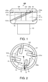
- FIG. 1 is a side view illustrating a configuration of an electrode part of a vacuum valve according to a first embodiment.
- FIG. 2 is a transparent top view of the electrode part of the vacuum valve according to the first embodiment, which is seen from a contact point side.
- FIG. 3 is a side view illustrating a configuration of an electrode part of a vacuum valve according to a second embodiment.
- FIG. 4 is a side view illustrating a configuration of an electrode part of a vacuum valve according to a third embodiment.
- FIG. 5 is a transparent top view of the electrode part of the vacuum valve according to the third embodiment, which is seen from a contact point side.
- FIG. 6 is a side view illustrating a configuration of an electrode part of a vacuum valve according to a fourth embodiment.
- FIG. 7 is a side view illustrating a configuration of an electrode part of a vacuum valve according to a fifth embodiment.
- FIG. 8 is a transparent top view of the electrode part of the vacuum valve according to the fifth embodiment, which is seen from a contact point side.
- FIG. 9 is a side view illustrating a configuration of an electrode part of a vacuum valve according to a sixth embodiment.
- FIG. 10 is a side view illustrating a configuration of an electrode part of a vacuum valve according to a seventh embodiment.
- FIG. 11 is a side view illustrating a configuration of an electrode part of a vacuum valve according to an eighth embodiment.
- FIG. 12 is a side view illustrating a configuration of an electrode part of a vacuum valve according to a ninth embodiment.
- FIG. 13 is a figure viewing from the arrow direction of the A-A line of FIG. 12 .
- FIG. 14 is a top view of a connecting plate of the vacuum valve according to the ninth embodiment, which is viewed from a contact point side.
- FIG. 15 is a sectional view illustrating an example of a configuration of a conventional vacuum valve.
- FIG. 1 is a side view illustrating a configuration of an electrode part of a vacuum valve according to a first embodiment
- FIG. 2 is a transparent top view of the electrode part of the vacuum valve according to the first embodiment, which is seen from a contact point side.
- the electrode part 100 of the vacuum valve according to the first embodiment includes an electrode 101 , a contact point 102 , a conductor 103 , a reinforcing member 104 and a connecting plate 105 .
- the electrode 101 is cup-shape. That is, the electrode 101 has a first surface which a hollow part 101 b is formed on.
- the electrode 101 is made of material with high electric conductivity, for example copper.
- Two or more spiral electrode slits 101 a which slantingly cross an axial direction of the electrode 101 are formed on the outer circumference of the electrode 101 .
- a first surface of the contact point 102 is fixed on the first surface of the electrode 101 .
- the contact point 102 is made of material which is excellent in the interruption performance, for example an alloy of copper and chromium.
- a second surface of the contact point 102 can be brought into contact or out of contact with a contact point (not shown) which is disposed to face the contact point 102 .
- the conductor 103 is fixed on a second surface of the electrode 101 , which second surface is opposite the first surface of the electrode 101 . Electric current flows into the conductor 103 in its axial direction.
- the reinforcing member 104 is disposed inside the hollow part 101 b .
- the reinforcing member 104 mechanically supports and fixes the bottom of the hollow part 101 b and the first surface of the contact point 102 .
- the reinforcing member 104 is made of, for example, insulating material or stainless steel.
- the contact point 102 has a first concavity 102 a on the first surface.
- the first concavity 102 a opens to the conductor 103 side.
- the connecting plate 105 is disposed inside the first concavity 102 a and is made of material whose resistivity is lower than one of the contact point 102 .
- Such material is, for example, copper.
- two or more connecting plate slits 105 a are formed on the connecting plate 105 and extend inward from the circumference of the connecting plate 105 as a starting point.
- the central axes 10 of the connecting plate slits 105 a incline in the rotatory direction of the spiral of the electrode slits 101 a against the line 13 which connects the center point 11 of the connecting plate 105 and the center point 12 of the radial direction on the starting point of the connecting plate slits 105 a.
- the electrode slits 101 a rise to right. Therefore, the rotatory direction of the spiral of the electrode slits 101 a is defined as “right”. That is, the central axes 10 of the connecting plate slits 105 a incline in right against the line 13 which connects the center point 11 of the connecting plate 105 and the center point 12 of the radial direction on the starting point of the connecting plate slits 105 a , as viewed from the contact point 102 side.
- the rotatory direction of the spiral of the electrode slits 101 a is defined as “left”, and the central axes 10 of the connecting plate slits 105 a incline in left against the line 13 which connects the center point 11 of the connecting plate 105 and the center point 12 of the radial direction on the starting point of the connecting plate slits 105 a , as viewed from the contact point 102 side.
- the first surface of the electrode 101 makes contact with both of the contact point 102 and the connecting plate 105 . Since the connecting plate 105 is made of material whose resistivity is lower than one of the contact point 102 , the resistance of the connecting plate 105 is small. Therefore, when electric current is interrupted, a lot of electric current which flows through the electrode part 100 flows through the conductor 103 , the electrode 101 , the connecting plate 105 and the contact point 102 in order. Then, it flows into the contact point (not shown) disposed to face the contact point 102 via an arc which occurs between the contact point 102 and the contact point (not shown).
- the central axes 10 of the connecting plate slits 105 a incline in the rotatory direction of the spiral of the electrode slits 101 a (it is “right” in FIG. 1 ) against the line 13 which connects the center point 11 of the connecting plate 105 and the center point 12 of the radial direction on the starting point of the connecting plate slits 105 a.
- the direction of electric current 15 which flows through the connecting plate 105 is limited by the connecting plate slits 105 a , as shown in FIG. 2 .
- a vertical magnetic field is also generated upward in FIG. 1 by circumferential-direction component of the electric current 15 which flows through the connecting plate 105 .
- the vacuum valve of the first embodiment in addition to the vertical magnetic field generated by the electric current 14 which flows through the electrode 101 , the same-direction vertical magnetic field is also generated by the electric current 15 which flows through the connecting plate 105 . Therefore, intensity of the vertical magnetic field which is generated between the contact point 102 and the contact point (not shown) disposed to face it can improve.
- the vacuum valve is configured so that at least a part of the electrode slits 101 a and the connecting plate slits 105 a may overlap, as viewed from the contact point 102 side. Therefore, when electric current flows from the electrode 101 into the connecting plate 105 , the electric current is prevented from flowing into the direction (electric current 16 ) by which the intensity of the vertical magnetic field is weakened, and the electric current easily flows into the direction (the electric current 15 ) by which the intensity of the vertical magnetic field is strengthened.
- FIG. 3 is a side view illustrating a configuration of an electrode part of a vacuum valve according to the second embodiment.
- the second embodiment differs from the first embodiment in that a gap 201 is formed between the electrode 101 and the contact point 102 .
- the electrode 101 makes contact with only the connecting plate 105 .
- FIG. 4 is a side view illustrating a configuration of an electrode part of a vacuum valve according to the third embodiment.
- FIG. 5 is a transparent top view of the electrode part of the vacuum valve according to the third embodiment, which is seen from a contact point side.
- the third embodiment differs from the first embodiment in including contacting portions 301 .
- the contacting portions 301 are formed between the electrode 101 and the contact point 102 . That is, the electrode 101 and the contact point 102 do not make contact with each other except the contacting portions 301 .
- the contacting portions 301 are located at the opposite side to the rotatory direction of the spiral of the electrode slits 101 a with respect to the electrode slits 101 a (left side along the circumferential direction with respect to the electrode slits 101 a in FIG. 5 ), as viewed from the contact point 102 side.
- the contacting portions 301 are disposed near the electrode slits 101 a .
- the connecting plate slits 105 a are disposed at the opposite side to the electrode slits 101 a , as viewed from the contacting portions 301 , and near the contacting portions 301 .
- the contacting portions 301 are located at the opposite side to the rotatory direction of the spiral of the electrode slits 101 a with respect to the electrode slits 101 a , as viewed from the contact point 102 side, and disposed near the electrode slits 101 a , the circumferential-direction component of the electric current 14 which flows through the electrode 101 increases. It is possible to further strengthen the intensity of the vertical magnetic field which is generated between the contact point 102 and the contact point (not shown) disposed to face it.
- FIG. 6 is a side view illustrating a configuration of an electrode part of a vacuum valve according to the fourth embodiment.
- the fourth embodiment differs from the first embodiment in that the connecting plate slits 105 a are formed as inclined along the direction of the spiral of the electrode slits 101 a.
- the direction of electric current which flows into the connecting plate 105 is limited by the connecting plate slits 105 a (electric current 17 in FIG. 6 ). Therefore, the circumferential-direction component of the electric current which flows through the connecting plate 105 increases. It is possible to further strengthen the intensity of the vertical magnetic field which is generated between the contact point 102 and the contact point (not shown) disposed to face it.
- FIG. 7 is a side view illustrating a configuration of an electrode part of a vacuum valve according to the fifth embodiment.
- FIG. 8 is a transparent top view of the electrode part of the vacuum valve according to the fifth embodiment, which is seen from a contact point side.
- the fifth embodiment differs from the first embodiment in that a hollow 501 is formed on the second surface of the contact point 102 .
- the connecting plate slits 105 a reach to the inside of the broken line A which corresponds to the hollow 501 from the starting point on the circumference of the connecting plate 105 . That is, the area C is located between the connecting plate slits 105 a.
- the direction of electric current which flows through the area C of the connecting plate 105 is limited by the connecting plate slits 105 a . Since the circumferential-direction component of the electric current increases, a high intensity vertical magnetic field is generated in the area C. The arc occurs in the contacting portion 18 corresponding to the area C in which the high intensity vertical magnetic field is generated by the hollow 501 . Therefore, the arc can be affected by the vertical magnetic field further.
- FIG. 9 is a side view illustrating a configuration of an electrode part of a vacuum valve according to the sixth embodiment.
- the sixth embodiment differs from the first embodiment in including a cylindrical magnetic substance 401 .
- the magnetic substance 401 is made of, for example pure iron, and disposed inside of the hollow part 101 b of the electrode 101 . Gaps are formed between the magnetic substance 401 and the inside surface of the electrode 101 , and between the magnetic substance 401 and the connecting plate 105 , respectively, so that they are not electrically connected each other. Instead of forming the gaps, a high resistant substance or an insulator may be disposed between the magnetic substance 401 and the inside surface of the electrode 101 , and between the magnetic substance 401 and the connecting plate 105 , respectively.
- the magnetic substance 401 which has low magnetic resistance is disposed inside of the hollow part 101 b of the electrode 101 . Therefore, it is possible to further strengthen the intensity of the vertical magnetic field which is generated between the contact point 102 and the contact point (not shown) disposed to face it, in addition to the effects obtained in the first embodiment.
- FIG. 10 is a side view illustrating a configuration of an electrode part of a vacuum valve according to the seventh embodiment.
- the seventh embodiment differs from the first embodiment in including a second concavity 701 .
- the arc can be affected by the vertical magnetic field further, and it is possible to control the arc more stably, in addition to the effects obtained in the first embodiment.
- FIG. 11 is a side view illustrating a configuration of an electrode part of a vacuum valve according to the eighth embodiment.
- the eighth embodiment differs from the sixth embodiment and the seventh embodiment in that the vacuum valve has the magnetic substance 401 and the second concavity 701 , and the magnetic substance 401 extends toward the inside of the second concavity 701 from the hollow part 101 b.
- the magnetic substance 401 is disposed near the arc which occurs between the contact point 102 and the contact point (not shown).
- the arc can be affected by the vertical magnetic field further, and it is possible to control the arc more stably, in addition to the effects obtained in the sixth embodiment or the seventh embodiment.
- FIG. 12 is a side view illustrating a configuration of an electrode part of a vacuum valve according to the ninth embodiment.
- FIG. 13 is a figure viewing from the arrow direction of the A-A line of FIG. 12 .
- FIG. 14 is a top view of a connecting plate of the vacuum valve according to the ninth embodiment, which is viewed from a contact point side. In FIGS. 12 to 14 , only one electrode part 900 of a pair of electrode parts is described.
- the ninth embodiment differs from the first embodiment in the electrode part 900 .
- the electrode part 900 includes a conductor 901 , a contact point 902 , an electrode 903 , and a connecting plate 904 .
- the electrode 903 includes an arm 905 , an arc part 906 , and a connecting pin 907 .
- the arm 905 which extends to an outer side in a vertical direction with respect to an axial direction of the conductor 901 is fixed to an axial end of the conductor 901 .
- the arc part 906 is supported at the tip of the arm 905 , and formed in an arc shape along the circumferential direction around the conductor 901 .
- the connecting pin 907 is formed at the tip of the arc part 906 .
- the arc part 906 is electrically connected with the contact point 902 via the connecting pin 907 .
- the contact point 902 can be brought into contact or out of contact with a contact point (not shown) which is disposed to face it.
- the contact point 902 has a first concavity 902 a which opens to the conductor 901 side.
- the connecting plate 904 is disposed inside the first concavity 902 a and is made of material whose resistivity is lower than one of the contact point 902 .
- Such material is, for example, copper.
- two or more connecting plate slits 904 a are formed on the connecting plate 904 and extend inward from the circumference of the connecting plate 904 as a starting point.
- the central axes 20 of the connecting plate slits 904 a incline in the opposite direction to the rotatory direction of electric current 24 which flows to the arc part 906 from the arm 905 against the line 23 which connects the center point 21 of the connecting plate 904 and the center point 22 of the radial direction on the starting point of the connecting plate slits 904 a.
- the central axes 20 of the connecting plate slits 904 a incline in right which is the opposite direction to the rotatory direction of the electric current 24 which flows to the arc part 906 from the arm 905 against the line 23 which connects the center point 21 of the connecting plate 904 and the center point 22 of the radial direction on the starting point of the connecting plate slits 904 a , as viewed from the contact point 902 side.
- an accidental current or a load current flows into the contact point (not shown) disposed to face the contact point 902 from the conductor 901 via the arm 905 , the arc part 906 , the connecting pin 907 , the connecting plate 904 , and the contact point 902 .
- a magnetic field (vertical magnetic field) is axially generated (upward in FIG. 12 ) between the contact point 902 and the contact point (not shown) by the electric current 24 which flows through the arc part 904 .
- the direction of electric current 25 which flows through the connecting plate 904 is limited by the connecting plate slits 904 a , as shown in FIG. 14 .
- a vertical magnetic field is also generated upward in FIG. 12 by circumferential-direction component of the electric current 25 which flows through the connecting plate slits 904 .
- the vacuum valve of the ninth embodiment in addition to the vertical magnetic field generated by the electric current 24 which flows through arc part 906 of the electrode 903 , the same-direction vertical magnetic field is also generated by the electric current 25 which flows through the connecting plate 904 . Therefore, intensity of the vertical magnetic field which is generated between the contact point 902 and the contact point (not shown) disposed to face it can improve.
Landscapes
- High-Tension Arc-Extinguishing Switches Without Spraying Means (AREA)
Applications Claiming Priority (3)
| Application Number | Priority Date | Filing Date | Title |
|---|---|---|---|
| JP2014085371A JP6268031B2 (ja) | 2014-04-17 | 2014-04-17 | 真空バルブ |
| JP2014-085371 | 2014-04-17 | ||
| PCT/JP2015/000872 WO2015159470A1 (ja) | 2014-04-17 | 2015-02-23 | 真空バルブ |
Related Parent Applications (1)
| Application Number | Title | Priority Date | Filing Date |
|---|---|---|---|
| PCT/JP2015/000872 Continuation WO2015159470A1 (ja) | 2014-04-17 | 2015-02-23 | 真空バルブ |
Publications (2)
| Publication Number | Publication Date |
|---|---|
| US20170032914A1 US20170032914A1 (en) | 2017-02-02 |
| US10026570B2 true US10026570B2 (en) | 2018-07-17 |
Family
ID=54323699
Family Applications (1)
| Application Number | Title | Priority Date | Filing Date |
|---|---|---|---|
| US15/295,263 Active US10026570B2 (en) | 2014-04-17 | 2016-10-17 | Vacuum valve |
Country Status (5)
| Country | Link |
|---|---|
| US (1) | US10026570B2 (de) |
| EP (1) | EP3133631B1 (de) |
| JP (1) | JP6268031B2 (de) |
| CN (1) | CN106233414B (de) |
| WO (1) | WO2015159470A1 (de) |
Families Citing this family (1)
| Publication number | Priority date | Publication date | Assignee | Title |
|---|---|---|---|---|
| JP7067879B2 (ja) * | 2017-07-14 | 2022-05-16 | 株式会社東芝 | 真空バルブ |
Citations (18)
| Publication number | Priority date | Publication date | Assignee | Title |
|---|---|---|---|---|
| US3980850A (en) * | 1974-12-19 | 1976-09-14 | Westinghouse Electric Corporation | Vacuum interrupter with cup-shaped contact having an inner arc controlling electrode |
| US4117288A (en) * | 1976-06-25 | 1978-09-26 | Westinghouse Electric Corp. | Vacuum type circuit interrupter with a contact having integral axial magnetic field means |
| US4210790A (en) * | 1976-06-09 | 1980-07-01 | Hitachi, Ltd. | Vacuum-type circuit interrupter |
| US4334133A (en) * | 1979-03-20 | 1982-06-08 | Siemens Aktiengesellschaft | Contact arrangement for vacuum switches |
| JPH01204322A (ja) | 1988-02-08 | 1989-08-16 | Toshiba Corp | 真空バルブ |
| JPH04155721A (ja) | 1990-10-18 | 1992-05-28 | Toshiba Corp | 真空バルブ |
| US5438174A (en) * | 1993-11-22 | 1995-08-01 | Eaton Corporation | Vacuum interrupter with a radial magnetic field |
| JPH0822751A (ja) | 1994-07-11 | 1996-01-23 | Toshiba Corp | 真空バルブ |
| JPH09115397A (ja) | 1995-10-20 | 1997-05-02 | Toshiba Corp | 真空バルブ |
| US5804788A (en) * | 1994-11-16 | 1998-09-08 | Eaton Corporation | Cylindrical coil and contact support for vacuum interrupter |
| US6072141A (en) * | 1994-09-22 | 2000-06-06 | Slamecka; Ernst | Vacuum switch contact arrangement |
| JP2002042617A (ja) | 2000-07-31 | 2002-02-08 | Toshiba Fa Syst Eng Corp | 真空バルブ |
| US6479779B1 (en) * | 1999-02-02 | 2002-11-12 | Alstom Uk Limited | Vacuum switching device |
| JP2008262772A (ja) | 2007-04-11 | 2008-10-30 | Toshiba Corp | 真空バルブ |
| WO2010052992A1 (ja) | 2008-11-04 | 2010-05-14 | 株式会社日本Aeパワーシステムズ | 真空遮断器用電極構造 |
| CN101834086A (zh) | 2009-03-11 | 2010-09-15 | Ls产电株式会社 | 用于真空断续器的电极 |
| JP2014049353A (ja) | 2012-08-31 | 2014-03-17 | Toshiba Corp | 固体絶縁スイッチギヤおよび固体絶縁スイッチギヤの真空バルブ |
| US20140131316A1 (en) * | 2011-07-23 | 2014-05-15 | Abb Technology Ag | Contact assembly for a vacuum circuit breaker |
Family Cites Families (5)
| Publication number | Priority date | Publication date | Assignee | Title |
|---|---|---|---|---|
| JP3568683B2 (ja) * | 1995-04-28 | 2004-09-22 | 株式会社東芝 | 真空バルブ |
| CN1205534A (zh) * | 1997-07-11 | 1999-01-20 | 株式会社日立制作所 | 真空断路器 |
| DE10027198B4 (de) * | 1999-06-04 | 2006-06-22 | Mitsubishi Denki K.K. | Elektrode für eine paarweise Anordnung in einem Vakuumrohr eines Vakuumschalters |
| JP5561715B2 (ja) * | 2009-10-14 | 2014-07-30 | キヤノンマシナリー株式会社 | ボンディング装置 |
| JP5281171B2 (ja) * | 2010-01-18 | 2013-09-04 | 三菱電機株式会社 | 真空バルブ |
-
2014
- 2014-04-17 JP JP2014085371A patent/JP6268031B2/ja active Active
-
2015
- 2015-02-23 EP EP15779643.4A patent/EP3133631B1/de active Active
- 2015-02-23 WO PCT/JP2015/000872 patent/WO2015159470A1/ja not_active Ceased
- 2015-02-23 CN CN201580020041.XA patent/CN106233414B/zh active Active
-
2016
- 2016-10-17 US US15/295,263 patent/US10026570B2/en active Active
Patent Citations (23)
| Publication number | Priority date | Publication date | Assignee | Title |
|---|---|---|---|---|
| US3980850A (en) * | 1974-12-19 | 1976-09-14 | Westinghouse Electric Corporation | Vacuum interrupter with cup-shaped contact having an inner arc controlling electrode |
| US4210790A (en) * | 1976-06-09 | 1980-07-01 | Hitachi, Ltd. | Vacuum-type circuit interrupter |
| US4117288A (en) * | 1976-06-25 | 1978-09-26 | Westinghouse Electric Corp. | Vacuum type circuit interrupter with a contact having integral axial magnetic field means |
| US4334133A (en) * | 1979-03-20 | 1982-06-08 | Siemens Aktiengesellschaft | Contact arrangement for vacuum switches |
| JPH01204322A (ja) | 1988-02-08 | 1989-08-16 | Toshiba Corp | 真空バルブ |
| JPH04155721A (ja) | 1990-10-18 | 1992-05-28 | Toshiba Corp | 真空バルブ |
| US5438174A (en) * | 1993-11-22 | 1995-08-01 | Eaton Corporation | Vacuum interrupter with a radial magnetic field |
| JPH0822751A (ja) | 1994-07-11 | 1996-01-23 | Toshiba Corp | 真空バルブ |
| US6072141A (en) * | 1994-09-22 | 2000-06-06 | Slamecka; Ernst | Vacuum switch contact arrangement |
| US5804788A (en) * | 1994-11-16 | 1998-09-08 | Eaton Corporation | Cylindrical coil and contact support for vacuum interrupter |
| JPH09115397A (ja) | 1995-10-20 | 1997-05-02 | Toshiba Corp | 真空バルブ |
| US6479779B1 (en) * | 1999-02-02 | 2002-11-12 | Alstom Uk Limited | Vacuum switching device |
| JP2002042617A (ja) | 2000-07-31 | 2002-02-08 | Toshiba Fa Syst Eng Corp | 真空バルブ |
| JP2008262772A (ja) | 2007-04-11 | 2008-10-30 | Toshiba Corp | 真空バルブ |
| JP2010113821A (ja) | 2008-11-04 | 2010-05-20 | Japan Ae Power Systems Corp | 真空遮断器用電極構造 |
| WO2010052992A1 (ja) | 2008-11-04 | 2010-05-14 | 株式会社日本Aeパワーシステムズ | 真空遮断器用電極構造 |
| EP2346061A1 (de) | 2008-11-04 | 2011-07-20 | Japan AE Power Systems Corporation | Elektrodenstruktur für einen vakuumschutzschalter |
| CN102187418A (zh) | 2008-11-04 | 2011-09-14 | 日本Ae帕瓦株式会社 | 真空断路器用电极结构 |
| US20110220613A1 (en) | 2008-11-04 | 2011-09-15 | Japan Ae Power Systems Corporation | Electrode structure for vacuum circuit breaker |
| CN101834086A (zh) | 2009-03-11 | 2010-09-15 | Ls产电株式会社 | 用于真空断续器的电极 |
| US20100230388A1 (en) | 2009-03-11 | 2010-09-16 | Ls Industrial Systems Co., Ltd. | Electrode for vacuum interrupter |
| US20140131316A1 (en) * | 2011-07-23 | 2014-05-15 | Abb Technology Ag | Contact assembly for a vacuum circuit breaker |
| JP2014049353A (ja) | 2012-08-31 | 2014-03-17 | Toshiba Corp | 固体絶縁スイッチギヤおよび固体絶縁スイッチギヤの真空バルブ |
Non-Patent Citations (3)
| Title |
|---|
| Extended European Search Report issued in counterpart European application No. 15779643.4, dated Jan. 2, 2018 (8 pages). |
| International Search Report issued in related Application No. PCT/JP2015/000872, dated Mar. 17, 2015 (9 pages). |
| Office Action issued in related CN Application No. 201580020041.X, dated Nov. 16, 2017 (9 pages). |
Also Published As
| Publication number | Publication date |
|---|---|
| EP3133631A1 (de) | 2017-02-22 |
| EP3133631A4 (de) | 2018-01-24 |
| JP2015207348A (ja) | 2015-11-19 |
| US20170032914A1 (en) | 2017-02-02 |
| CN106233414B (zh) | 2019-05-31 |
| JP6268031B2 (ja) | 2018-01-24 |
| CN106233414A (zh) | 2016-12-14 |
| WO2015159470A1 (ja) | 2015-10-22 |
| EP3133631B1 (de) | 2019-01-09 |
Similar Documents
| Publication | Publication Date | Title |
|---|---|---|
| US10614980B2 (en) | Vacuum bottle for electrical switching device | |
| TWI405921B (zh) | 真空閥 | |
| US9006600B2 (en) | High current vacuum interrupter with sectional electrode and multi heat pipes | |
| US3372259A (en) | Vacuum-type electric circuit interrupter with arc-voltage limiting means | |
| US10026570B2 (en) | Vacuum valve | |
| JP6808397B2 (ja) | 真空バルブ | |
| JP5197065B2 (ja) | 真空バルブ | |
| US9496106B2 (en) | Electrode assembly and vacuum interrupter including the same | |
| US9852858B2 (en) | Contact of vacuum interrupter | |
| JP2016048636A (ja) | 真空バルブ | |
| JP6138601B2 (ja) | 真空遮断器用電極及びそれを用いた真空バルブ | |
| JP5525316B2 (ja) | 真空バルブ | |
| JP5475601B2 (ja) | 真空バルブ | |
| JP2015023008A (ja) | 真空バルブ | |
| US9330869B2 (en) | Vacuum valve | |
| JP2009289660A (ja) | 真空バルブ | |
| JP2014127280A (ja) | 真空バルブ | |
| US12283444B2 (en) | Vacuum interrupter | |
| JP5556596B2 (ja) | 真空バルブ | |
| KR20120006447A (ko) | 진공 밸브 | |
| JP2014049353A (ja) | 固体絶縁スイッチギヤおよび固体絶縁スイッチギヤの真空バルブ | |
| JP6395642B2 (ja) | 真空バルブ | |
| JP2013242978A (ja) | 真空バルブ | |
| CN101326606A (zh) | 真空开关管 | |
| JP2019200914A (ja) | 真空バルブ |
Legal Events
| Date | Code | Title | Description |
|---|---|---|---|
| AS | Assignment |
Owner name: KABUSHIKI KAISHA TOSHIBA, JAPAN Free format text: ASSIGNMENT OF ASSIGNORS INTEREST;ASSIGNORS:NIWA, YOSHIMITSU;SAKAGUCHI, WATARU;SEKIMORI, YUKI;REEL/FRAME:040032/0534 Effective date: 20160823 |
|
| STCF | Information on status: patent grant |
Free format text: PATENTED CASE |
|
| MAFP | Maintenance fee payment |
Free format text: PAYMENT OF MAINTENANCE FEE, 4TH YEAR, LARGE ENTITY (ORIGINAL EVENT CODE: M1551); ENTITY STATUS OF PATENT OWNER: LARGE ENTITY Year of fee payment: 4 |
|
| MAFP | Maintenance fee payment |
Free format text: PAYMENT OF MAINTENANCE FEE, 8TH YEAR, LARGE ENTITY (ORIGINAL EVENT CODE: M1552); ENTITY STATUS OF PATENT OWNER: LARGE ENTITY Year of fee payment: 8 |