EP3133631B1 - Vakuumventil - Google Patents
Vakuumventil Download PDFInfo
- Publication number
- EP3133631B1 EP3133631B1 EP15779643.4A EP15779643A EP3133631B1 EP 3133631 B1 EP3133631 B1 EP 3133631B1 EP 15779643 A EP15779643 A EP 15779643A EP 3133631 B1 EP3133631 B1 EP 3133631B1
- Authority
- EP
- European Patent Office
- Prior art keywords
- connecting plate
- electrode
- contact point
- vacuum valve
- slits
- Prior art date
- Legal status (The legal status is an assumption and is not a legal conclusion. Google has not performed a legal analysis and makes no representation as to the accuracy of the status listed.)
- Active
Links
Images


Classifications
-
- H—ELECTRICITY
- H01—ELECTRIC ELEMENTS
- H01H—ELECTRIC SWITCHES; RELAYS; SELECTORS; EMERGENCY PROTECTIVE DEVICES
- H01H33/00—High-tension or heavy-current switches with arc-extinguishing or arc-preventing means
- H01H33/60—Switches wherein the means for extinguishing or preventing the arc do not include separate means for obtaining or increasing flow of arc-extinguishing fluid
- H01H33/66—Vacuum switches
- H01H33/664—Contacts; Arc-extinguishing means, e.g. arcing rings
- H01H33/6646—Contacts; Arc-extinguishing means, e.g. arcing rings having non flat disc-like contact surface
-
- H—ELECTRICITY
- H01—ELECTRIC ELEMENTS
- H01H—ELECTRIC SWITCHES; RELAYS; SELECTORS; EMERGENCY PROTECTIVE DEVICES
- H01H33/00—High-tension or heavy-current switches with arc-extinguishing or arc-preventing means
- H01H33/60—Switches wherein the means for extinguishing or preventing the arc do not include separate means for obtaining or increasing flow of arc-extinguishing fluid
- H01H33/66—Vacuum switches
- H01H33/664—Contacts; Arc-extinguishing means, e.g. arcing rings
-
- H—ELECTRICITY
- H01—ELECTRIC ELEMENTS
- H01H—ELECTRIC SWITCHES; RELAYS; SELECTORS; EMERGENCY PROTECTIVE DEVICES
- H01H1/00—Contacts
- H01H1/06—Contacts characterised by the shape or structure of the contact-making surface, e.g. grooved
-
- H—ELECTRICITY
- H01—ELECTRIC ELEMENTS
- H01H—ELECTRIC SWITCHES; RELAYS; SELECTORS; EMERGENCY PROTECTIVE DEVICES
- H01H33/00—High-tension or heavy-current switches with arc-extinguishing or arc-preventing means
- H01H33/60—Switches wherein the means for extinguishing or preventing the arc do not include separate means for obtaining or increasing flow of arc-extinguishing fluid
- H01H33/66—Vacuum switches
- H01H33/664—Contacts; Arc-extinguishing means, e.g. arcing rings
- H01H33/6642—Contacts; Arc-extinguishing means, e.g. arcing rings having cup-shaped contacts, the cylindrical wall of which being provided with inclined slits to form a coil
-
- H—ELECTRICITY
- H01—ELECTRIC ELEMENTS
- H01H—ELECTRIC SWITCHES; RELAYS; SELECTORS; EMERGENCY PROTECTIVE DEVICES
- H01H33/00—High-tension or heavy-current switches with arc-extinguishing or arc-preventing means
- H01H33/60—Switches wherein the means for extinguishing or preventing the arc do not include separate means for obtaining or increasing flow of arc-extinguishing fluid
- H01H33/66—Vacuum switches
- H01H33/664—Contacts; Arc-extinguishing means, e.g. arcing rings
- H01H33/6643—Contacts; Arc-extinguishing means, e.g. arcing rings having disc-shaped contacts subdivided in petal-like segments, e.g. by helical grooves
Definitions
- Embodiments of the present disclosure relate to a vacuum valve.
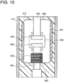
- FIG. 15 is a sectional view illustrating an example of a configuration of a conventional vacuum valve.
- Openings on both ends of an insulation vessel 601 made of, for example, ceramics, are sealed with a fixed side sealing metal fitting 602 and a movable side sealing metal fitting 603, respectively.
- a fixed side conductor 604 passes through the fixed side sealing metal fitting 602, and is fixed to it.
- a fixed side electrode 605 is fixed to one end of the fixed side conductor 604.
- a movable side electrode 606 is disposed to face the fixed side electrode 605.
- the movable side electrode 606 is fixed to one end of a movable side conductor 607 which passes though an opening of the movable side sealing metal fitting 603, and can move along the opening.
- a magnetic field (vertical magnetic field) is axially generated by the fixed side electrode 605 and the movable side electrode 606.
- One end of elastic bellows 608 is fixed to the intermediate part of the movable side conductor 607.
- the other end of the bellows 608 is fixed to the movable side sealing metal fitting 603.
- a cylindrical shield 609 is disposed to surround the electrodes 605, 606 and is fixed to the inside of the insulation vessel 601.
- the vacuum valve configured as mentioned above is molded by insulating material, for example a resin, and an insulating part 610 is formed.
- a conductive part 611 is formed on the outer circumference of the insulating part 610 by application of conductive paint.
- the conductive paint is, for example, silver paint.
- the movable side conductor 607 which is connected to the operating mechanism moves axially. Then, the fixed electrode 605 and the movable electrode 606 can be electrically brought into contact or out of contact with each other. When the fixed electrode 605 and the movable electrode 606 are separated from each other, an arc occurs. However, the arc is diffused throughout contact points of the electrodes 605,606 by the effect of the vertical magnetic field.
- JP H09 115397A discloses a vacuum valve including a contact, a conduction plate, a cup electrode having slits, and a movable conduction shaft.
- JP H08 22751A discloses a vacuum valve including a contact and a movable electrode.
- US 3 980 850 discloses a vacuum interrupter including a side wall having angled slots, a reentrant lip portion and an open center.
- JP H04 155721 A discloses a vacuum valve including a contact 3 and an electrode.
- An even further prior art document is JP 2008-26772 A .
- the intensity of the vertical magnetic field is lower. It may be difficult for the vertical magnetic field to diffuse the arc throughout the contact points of the electrodes 605,606. If the curvature radius at the ends of the contact points of the electrodes 605,606 is enlarged for electric field relief, the thickness of the contact points becomes thick, and the distance between the electrodes 605,606 and the arc also becomes large. Therefore, the intensity of the vertical magnetic field lowers, and it may be necessary to enlarge the electrodes 605,606 in order to interrupt high electric current.
- a vacuum valve according to embodiments of the present disclosure comprises the features of claim 1. Embodiments are named in the dependent claims.
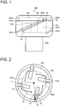
- FIG. 1 is a side view illustrating a configuration of an electrode part of a vacuum valve according to a first embodiment
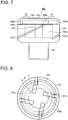
- FIG. 2 is a transparent top view of the electrode part of the vacuum valve according to the first embodiment, which is seen from a contact point side.
- the electrode part 100 of the vacuum valve according to the first embodiment includes an electrode 101, a contact point 102, a conductor 103, a reinforcing member 104 and a connecting plate 105.
- the electrode 101 is cup-shape. That is, the electrode 101 has a first surface which a hollow part 101b is formed on.
- the electrode 101 is made of material with high electric conductivity, for example copper.
- Two or more spiral electrode slits 101a which slantingly cross an axial direction of the electrode 101 are formed on the outer circumference of the electrode 101.
- a first surface of the contact point 102 is fixed on the first surface of the electrode 101.
- the contact point 102 is made of material which is excellent in the interruption performance, for example an alloy of copper and chromium.
- a second surface of the contact point 102 can be brought into contact or out of contact with a contact point (not shown) which is disposed to face the contact point 102.
- the conductor 103 is fixed on a second surface of the electrode 101, which second surface is opposite the first surface of the electrode 101. Electric current flows into the conductor 103 in its axial direction.
- the reinforcing member 104 is disposed inside the hollow part 101b.
- the reinforcing member 104 mechanically supports and fixes the bottom of the hollow part 101b and the first surface of the contact point 102.
- the reinforcing member 104 is made of, for example, insulating material or stainless steel.
- the contact point 102 has a first concavity 102a on the first surface.
- the first concavity 102a opens to the conductor 103 side.
- the connecting plate 105 is disposed inside the first concavity 102a and is made of material whose resistivity is lower than one of the contact point 102. Such material is, for example, copper.
- two or more connecting plate slits 105a are formed on the connecting plate 105 and extend inward from the circumference of the connecting plate 105 as a starting point.
- the central axes 10 of the connecting plate slits 105a incline in the rotatory direction of the spiral of the electrode slits 101a against the line 13 which connects the center point 11 of the connecting plate 105 and the center point 12 of the radial direction on the starting point of the connecting plate slits 105a.
- the electrode slits 101a rise to right. Therefore, the rotatory direction of the spiral of the electrode slits 101a is defined as "right". That is, the central axes 10 of the connecting plate slits 105a incline in right against the line 13 which connects the center point 11 of the connecting plate 105 and the center point 12 of the radial direction on the starting point of the connecting plate slits 105a, as viewed from the contact point 102 side.
- the rotatory direction of the spiral of the electrode slits 101a is defined as "left"
- the central axes 10 of the connecting plate slits 105a incline in left against the line 13 which connects the center point 11 of the connecting plate 105 and the center point 12 of the radial direction on the starting point of the connecting plate slits 105a, as viewed from the contact point 102 side.
- the first surface of the electrode 101 makes contact with both of the contact point 102 and the connecting plate 105. Since the connecting plate 105 is made of material whose resistivity is lower than one of the contact point 102, the resistance of the connecting plate 105 is small. Therefore, when electric current is interrupted, a lot of electric current which flows through the electrode part 100 flows through the conductor 103, the electrode 101, the connecting plate 105 and the contact point 102 in order. Then, it flows into the contact point (not shown) disposed to face the contact point 102 via an arc which occurs between the contact point 102 and the contact point (not shown).
- the direction of electric current 14 which flows from the conductor 13 into the electrode 101 is limited by the electrode slits 101a. That is, the electric current 14 passes between the electrode slits 101a, as shown in FIG. 1 . Therefore, a vertical magnetic field is generated upward in FIG. 1 by circumferential-direction component of the electric current 14 which flows through the electrode 101.
- the central axes 10 of the connecting plate slits 105a incline in the rotatory direction of the spiral of the electrode slits 101a (it is "right” in FIG. 1 ) against the line 13 which connects the center point 11 of the connecting plate 105 and the center point 12 of the radial direction on the starting point of the connecting plate slits 105a.
- the direction of electric current 15 which flows through the connecting plate 105 is limited by the connecting plate slits 105a, as shown in FIG. 2 .
- a vertical magnetic field is also generated upward in FIG. 1 by circumferential-direction component of the electric current 15 which flows through the connecting plate 105.
- the vacuum valve of the first embodiment in addition to the vertical magnetic field generated by the electric current 14 which flows through the electrode 101, the same-direction vertical magnetic field is also generated by the electric current 15 which flows through the connecting plate 105. Therefore, intensity of the vertical magnetic field which is generated between the contact point 102 and the contact point (not shown) disposed to face it can improve.
- the vacuum valve is configured so that at least a part of the electrode slits 101a and the connecting plate slits 105a may overlap, as viewed from the contact point 102 side. Therefore, when electric current flows from the electrode 101 into the connecting plate 105, the electric current is prevented from flowing into the direction (electric current 16) by which the intensity of the vertical magnetic field is weakened, and the electric current easily flows into the direction (the electric current 15) by which the intensity of the vertical magnetic field is strengthened.
- FIG. 3 is a side view illustrating a configuration of an electrode part of a vacuum valve according to the second embodiment.
- the second embodiment differs from the first embodiment in that a gap 201 is formed between the electrode 101 and the contact point 102.
- the electrode 101 makes contact with only the connecting plate 105.
- FIG. 4 is a side view illustrating a configuration of an electrode part of a vacuum valve according to the third embodiment.
- FIG. 5 is a transparent top view of the electrode part of the vacuum valve according to the third embodiment, which is seen from a contact point side.
- the third embodiment differs from the first embodiment in including contacting portions 301.
- the contacting portions 301 are formed between the electrode 101 and the contact point 102. That is, the electrode 101 and the contact point 102 do not make contact with each other except the contacting portions 301.
- the contacting portions 301 are located at the opposite side to the rotatory direction of the spiral of the electrode slits 101a with respect to the electrode slits 101a (left side along the circumferential direction with respect to the electrode slits 101a in FIG. 5 ), as viewed from the contact point 102 side.
- the contacting portions 301 are disposed near the electrode slits 101a.
- the connecting plate slits 105a are disposed at the opposite side to the electrode slits 101a, as viewed from the contacting portions 301, and near the contacting portions 301.
- the contacting portions 301 are located at the opposite side to the rotatory direction of the spiral of the electrode slits 101a with respect to the electrode slits 101a, as viewed from the contact point 102 side, and disposed near the electrode slits 101a, the circumferential-direction component of the electric current 14 which flows through the electrode 101 increases. It is possible to further strengthen the intensity of the vertical magnetic field which is generated between the contact point 102 and the contact point (not shown) disposed to face it.
- FIG. 6 is a side view illustrating a configuration of an electrode part of a vacuum valve according to the fourth embodiment.
- the fourth embodiment differs from the first embodiment in that the connecting plate slits 105a are formed as inclined along the direction of the spiral of the electrode slits 101a.
- the direction of electric current which flows into the connecting plate 105 is limited by the connecting plate slits 105a (electric current 17 in FIG. 6 ). Therefore, the circumferential-direction component of the electric current which flows through the connecting plate 105 increases. It is possible to further strengthen the intensity of the vertical magnetic field which is generated between the contact point 102 and the contact point (not shown) disposed to face it.
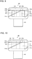
- FIG. 7 is a side view illustrating a configuration of an electrode part of a vacuum valve according to the fifth embodiment.
- FIG. 8 is a transparent top view of the electrode part of the vacuum valve according to the fifth embodiment, which is seen from a contact point side.
- the fifth embodiment differs from the first embodiment in that a hollow 501 is formed on the second surface of the contact point 102.
- the contact point 102 When the contact point 102 is brought into contact with the contact point (not shown) which is disposed to face it, they are brought into contact with each other in the contacting portion 18. That is because the hollow 501 is formed on the second surface of the contact point 102. The arc occurs in the contacting portion 18 when the contact points are separated from each other.
- the inside of the broken line A corresponds to the hollow 501 in FIG. 8 .
- the area C surrounded with broken line A and broken line B corresponds to the contacting portion 18 in FIG. 8 .
- the connecting plate slits 105a reach to the inside of the broken line A which corresponds to the hollow 501 from the starting point on the circumference of the connecting plate 105. That is, the area C is located between the connecting plate slits 105a.
- the direction of electric current which flows through the area C of the connecting plate 105 is limited by the connecting plate slits 105a. Since the circumferential-direction component of the electric current increases, a high intensity vertical magnetic field is generated in the area C. The arc occurs in the contacting portion 18 corresponding to the area C in which the high intensity vertical magnetic field is generated by the hollow 501. Therefore, the arc can be affected by the vertical magnetic field further.
- FIG. 9 is a side view illustrating a configuration of an electrode part of a vacuum valve according to the sixth embodiment.
- the sixth embodiment differs from the first embodiment in including a cylindrical magnetic substance 401.
- the magnetic substance 401 is made of, for example pure iron, and disposed inside of the hollow part 101b of the electrode 101. Gaps are formed between the magnetic substance 401 and the inside surface of the electrode 101, and between the magnetic substance 401 and the connecting plate 105, respectively, so that they are not electrically connected each other. Instead of forming the gaps, a high resistant substance or an insulator may be disposed between the magnetic substance 401 and the inside surface of the electrode 101, and between the magnetic substance 401 and the connecting plate 105, respectively.
- the magnetic substance 401 which has low magnetic resistance is disposed inside of the hollow part 101b of the electrode 101. Therefore, it is possible to further strengthen the intensity of the vertical magnetic field which is generated between the contact point 102 and the contact point (not shown) disposed to face it, in addition to the effects obtained in the first embodiment.
- FIG. 10 is a side view illustrating a configuration of an electrode part of a vacuum valve according to the seventh embodiment.
- the seventh embodiment differs from the first embodiment in including a second concavity 701.
- the connecting plate 105 has a second concavity 701 which opens to the conductor 103 side.
- the size of the radial direction of the second concavity 701 is almost the same (including just the same) as the size of the hollow part 101b.
- the connecting plate 105 has the second concavity 701. Therefore, electric current which flows through the connecting plate 105 passes near the contact point 102, that is, the electric current passes near the arc which occurs between the contact point 102 and the contact point (not shown).
- the arc can be affected by the vertical magnetic field further, and it is possible to control the arc more stably, in addition to the effects obtained in the first embodiment.
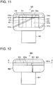
- FIG. 11 is a side view illustrating a configuration of an electrode part of a vacuum valve according to the eighth embodiment.
- the eighth embodiment differs from the sixth embodiment and the seventh embodiment in that the vacuum valve has the magnetic substance 401 and the second concavity 701, and the magnetic substance 401 extends toward the inside of the second concavity 701 from the hollow part 101b.
- the magnetic substance 401 is disposed near the arc which occurs between the contact point 102 and the contact point (not shown).
- the arc can be affected by the vertical magnetic field further, and it is possible to control the arc more stably, in addition to the effects obtained in the sixth embodiment or the seventh embodiment.
- FIG. 12 is a side view illustrating a configuration of an electrode part of a vacuum valve according to the ninth embodiment.
- FIG. 13 is a figure viewing from the arrow direction of the A-A line of FIG. 12 .
- FIG. 14 is a top view of a connecting plate of the vacuum valve according to the ninth embodiment, which is viewed from a contact point side. In FIGS. 12 to 14 , only one electrode part 900 of a pair of electrode parts is described.
- the ninth embodiment differs from the first embodiment in the electrode part 900.
- the electrode part 900 includes a conductor 901, a contact point 902, an electrode 903, and a connecting plate 904.
- the electrode 903 includes an arm 905, an arc part 906, and a connecting pin 907.
- the arm 905 which extends to an outer side in a vertical direction with respect to an axial direction of the conductor 901 is fixed to an axial end of the conductor 901.
- the arc part 906 is supported at the tip of the arm 905, and formed in an arc shape along the circumferential direction around the conductor 901.
- the connecting pin 907 is formed at the tip of the arc part 906.
- the arc part 906 is electrically connected with the contact point 902 via the connecting pin 907.
- the contact point 902 can be brought into contact or out of contact with a contact point (not shown) which is disposed to face it.
- the contact point 902 has a first concavity 902a which opens to the conductor 901 side.
- the connecting plate 904 is disposed inside the first concavity 902a and is made of material whose resistivity is lower than one of the contact point 902. Such material is, for example, copper.
- two or more connecting plate slits 904a are formed on the connecting plate 904 and extend inward from the circumference of the connecting plate 904 as a starting point.
- the central axes 20 of the connecting plate slits 904a incline in the opposite direction to the rotatory direction of electric current 24 which flows to the arc part 906 from the arm 905 against the line 23 which connects the center point 21 of the connecting plate 904 and the center point 22 of the radial direction on the starting point of the connecting plate slits 904a.
- the central axes 20 of the connecting plate slits 904a incline in right which is the opposite direction to the rotatory direction of the electric current 24 which flows to the arc part 906 from the arm 905 against the line 23 which connects the center point 21 of the connecting plate 904 and the center point 22 of the radial direction on the starting point of the connecting plate slits 904a, as viewed from the contact point 902 side.
- a magnetic field (vertical magnetic field) is axially generated (upward in FIG. 12 ) between the contact point 902 and the contact point (not shown) by the electric current 24 which flows through the arc part 904.
- the direction of electric current 25 which flows through the connecting plate 904 is limited by the connecting plate slits 904a, as shown in FIG. 14 .
- a vertical magnetic field is also generated upward in FIG. 12 by circumferential-direction component of the electric current 25 which flows through the connecting plate slits 904.
- the vacuum valve of the ninth embodiment in addition to the vertical magnetic field generated by the electric current 24 which flows through arc part 906 of the electrode 903, the same-direction vertical magnetic field is also generated by the electric current 25 which flows through the connecting plate 904. Therefore, intensity of the vertical magnetic field which is generated between the contact point 902 and the contact point (not shown) disposed to face it can improve.
Landscapes
- High-Tension Arc-Extinguishing Switches Without Spraying Means (AREA)
Claims (9)
- Vakuumventil, umfassend:eine Elektrode (101), die eine erste Oberfläche aufweist, an der ein Hohlteil (101b) geformt ist, in dem spiralförmige Elektrodenschlitze (101a) schräg geformt sind und eine axiale Richtung am Außenumfang der Elektrode queren;einen Leiter (103), der auf einer zweiten Oberfläche der Elektrode befestigt ist, wobei die zweite Oberfläche gegenüber der ersten Oberfläche liegt;einen Kontaktpunkt (102); undeine Verbindungsplatte (105), wobei Verbindungsplattenschlitze auf der Verbindungsplatte geformt sind,wobei sich zentrale Achsen der Verbindungsplattenschlitze (105a) in eine Drehrichtung der Spirale der Elektrodenschlitze gegen eine Linie (13) neigen, die einen zentralen Punkt (11) der Verbindungsplatte (105) und einen zentralen Punkt (12) einer radialen Richtung am Ausgangspunkt der Verbindungsplattenschlitze, von der Seite des Kontaktpunkts (102) aus betrachtet, verbindet, dadurch gekennzeichnet, dassder Kontaktpunkt eine erste Konkavität (102a) aufweist, die sich zu der Leiterseite hin öffnet, wobei der Kontaktpunkt auf der ersten Oberfläche der Elektrode befestigt ist, wobei die Verbindungsplatte (105) innerhalb der ersten Konkavität angeordnet ist;der spezifische Widerstand der Verbindungsplatte niedriger ist als der Kontaktpunkt, undsich die Verbindungsplattenschlitze vom Umfang als Ausgangspunkt nach innen erstrecken.
- Vakuumventil nach Anspruch 1, wobei sich mindestens ein Teil der Elektrodenschlitze (101a) und der Verbindungsplattenschlitze, von der Seite des Kontaktpunkts aus betrachtet, überlappen.
- Vakuumventil nach Anspruch 1 oder 2, wobei zwischen der Elektrode (101) und dem Kontaktpunkt (102) eine Spalte (201) geformt ist, und die Elektrode mit der Verbindungsplatte (105) einen Kontakt herstellt.
- Vakuumventil nach Anspruch 1 oder 2, wobei mindestens ein kontaktierender Punkt zwischen der Elektrode und dem Kontaktpunkt gebildet ist.
- Vakuumventil nach einem der Ansprüche 1-4, wobei die Verbindungsplattenschlitze als entlang einer Richtung der Spirale der Elektrodenschlitze geneigt geformt sind.
- Vakuumventil nach einem der Ansprüche 1-5, wobei an der zweiten Oberfläche des Kontaktpunkts ein Hohlraum (501) gebildet ist, und die Verbindungsplattenschlitze zu einer Position reichen, die dem Hohlraum vom Ausgangspunkt am Umfang der Verbindungsplatte entsprechen.
- Vakuumventil nach einem der Ansprüche 1-6, wobei die Verbindungsplatte eine zweite Konkavität (701) aufweist, die sich zur Leiterseite hin öffnet, und die Größe einer radialen Richtung der zweiten Konkavität fast gleich ist wie die Größe des Hohlteils.
- Vakuumventil nach Anspruch 7, wobei eine magnetische Substanz (401) im Inneren des Hohlteils angeordnet ist.
- Vakuumventil nach Anspruch 8, wobei sich die magnetische Substanz vom Hohlteil in das Innere der zweiten Konkavität hin erstreckt.
Applications Claiming Priority (2)
| Application Number | Priority Date | Filing Date | Title |
|---|---|---|---|
| JP2014085371A JP6268031B2 (ja) | 2014-04-17 | 2014-04-17 | 真空バルブ |
| PCT/JP2015/000872 WO2015159470A1 (ja) | 2014-04-17 | 2015-02-23 | 真空バルブ |
Publications (3)
| Publication Number | Publication Date |
|---|---|
| EP3133631A1 EP3133631A1 (de) | 2017-02-22 |
| EP3133631A4 EP3133631A4 (de) | 2018-01-24 |
| EP3133631B1 true EP3133631B1 (de) | 2019-01-09 |
Family
ID=54323699
Family Applications (1)
| Application Number | Title | Priority Date | Filing Date |
|---|---|---|---|
| EP15779643.4A Active EP3133631B1 (de) | 2014-04-17 | 2015-02-23 | Vakuumventil |
Country Status (5)
| Country | Link |
|---|---|
| US (1) | US10026570B2 (de) |
| EP (1) | EP3133631B1 (de) |
| JP (1) | JP6268031B2 (de) |
| CN (1) | CN106233414B (de) |
| WO (1) | WO2015159470A1 (de) |
Families Citing this family (1)
| Publication number | Priority date | Publication date | Assignee | Title |
|---|---|---|---|---|
| JP7067879B2 (ja) * | 2017-07-14 | 2022-05-16 | 株式会社東芝 | 真空バルブ |
Family Cites Families (23)
| Publication number | Priority date | Publication date | Assignee | Title |
|---|---|---|---|---|
| US3980850A (en) * | 1974-12-19 | 1976-09-14 | Westinghouse Electric Corporation | Vacuum interrupter with cup-shaped contact having an inner arc controlling electrode |
| JPS52150571A (en) * | 1976-06-09 | 1977-12-14 | Hitachi Ltd | Vacuum breaker electrode |
| US4117288A (en) * | 1976-06-25 | 1978-09-26 | Westinghouse Electric Corp. | Vacuum type circuit interrupter with a contact having integral axial magnetic field means |
| EP0017076B1 (de) * | 1979-03-30 | 1983-05-11 | Siemens Aktiengesellschaft | Kontaktanordnung für Vacuumschalter und Verfahren zu ihrer Herstellung |
| JPH01204322A (ja) * | 1988-02-08 | 1989-08-16 | Toshiba Corp | 真空バルブ |
| JPH04155721A (ja) * | 1990-10-18 | 1992-05-28 | Toshiba Corp | 真空バルブ |
| US5438174A (en) * | 1993-11-22 | 1995-08-01 | Eaton Corporation | Vacuum interrupter with a radial magnetic field |
| JPH0822751A (ja) * | 1994-07-11 | 1996-01-23 | Toshiba Corp | 真空バルブ |
| WO1996009637A1 (de) * | 1994-09-22 | 1996-03-28 | Ernst Slamecka | Vakuumschalter-kontaktanordnung |
| KR100361390B1 (ko) * | 1994-11-16 | 2003-02-19 | 이턴 코포레이션 | 진공차단기,진공차단기용접점코일조립체및원주전극코일의제조방법 |
| JP3568683B2 (ja) * | 1995-04-28 | 2004-09-22 | 株式会社東芝 | 真空バルブ |
| JPH09115397A (ja) * | 1995-10-20 | 1997-05-02 | Toshiba Corp | 真空バルブ |
| CN1205534A (zh) * | 1997-07-11 | 1999-01-20 | 株式会社日立制作所 | 真空断路器 |
| GB2338111B (en) * | 1999-02-02 | 2001-03-21 | Alstom Uk Ltd | Improvements relating to vacuum switching devices |
| DE10027198B4 (de) * | 1999-06-04 | 2006-06-22 | Mitsubishi Denki K.K. | Elektrode für eine paarweise Anordnung in einem Vakuumrohr eines Vakuumschalters |
| JP2002042617A (ja) * | 2000-07-31 | 2002-02-08 | Toshiba Fa Syst Eng Corp | 真空バルブ |
| JP4966076B2 (ja) * | 2007-04-11 | 2012-07-04 | 株式会社東芝 | 真空バルブ |
| JP2010113821A (ja) | 2008-11-04 | 2010-05-20 | Japan Ae Power Systems Corp | 真空遮断器用電極構造 |
| KR101261967B1 (ko) | 2009-03-11 | 2013-05-08 | 엘에스산전 주식회사 | 진공인터럽터의 전극 |
| JP5561715B2 (ja) * | 2009-10-14 | 2014-07-30 | キヤノンマシナリー株式会社 | ボンディング装置 |
| JP5281171B2 (ja) * | 2010-01-18 | 2013-09-04 | 三菱電機株式会社 | 真空バルブ |
| EP2551878A1 (de) * | 2011-07-23 | 2013-01-30 | ABB Technology AG | Kontaktanordnung für einen Vakuumschalter |
| JP2014049353A (ja) * | 2012-08-31 | 2014-03-17 | Toshiba Corp | 固体絶縁スイッチギヤおよび固体絶縁スイッチギヤの真空バルブ |
-
2014
- 2014-04-17 JP JP2014085371A patent/JP6268031B2/ja active Active
-
2015
- 2015-02-23 EP EP15779643.4A patent/EP3133631B1/de active Active
- 2015-02-23 WO PCT/JP2015/000872 patent/WO2015159470A1/ja not_active Ceased
- 2015-02-23 CN CN201580020041.XA patent/CN106233414B/zh active Active
-
2016
- 2016-10-17 US US15/295,263 patent/US10026570B2/en active Active
Non-Patent Citations (1)
| Title |
|---|
| None * |
Also Published As
| Publication number | Publication date |
|---|---|
| EP3133631A1 (de) | 2017-02-22 |
| EP3133631A4 (de) | 2018-01-24 |
| JP2015207348A (ja) | 2015-11-19 |
| US20170032914A1 (en) | 2017-02-02 |
| US10026570B2 (en) | 2018-07-17 |
| CN106233414B (zh) | 2019-05-31 |
| JP6268031B2 (ja) | 2018-01-24 |
| CN106233414A (zh) | 2016-12-14 |
| WO2015159470A1 (ja) | 2015-10-22 |
Similar Documents
| Publication | Publication Date | Title |
|---|---|---|
| US10614980B2 (en) | Vacuum bottle for electrical switching device | |
| US9006600B2 (en) | High current vacuum interrupter with sectional electrode and multi heat pipes | |
| JP5243575B2 (ja) | 真空遮断器 | |
| US3372259A (en) | Vacuum-type electric circuit interrupter with arc-voltage limiting means | |
| EP3133631B1 (de) | Vakuumventil | |
| JP5197065B2 (ja) | 真空バルブ | |
| US6674039B1 (en) | Contact arrangement for a vacuum interrupter | |
| US11756756B2 (en) | Vacuum interrupter with double live shield | |
| US9496106B2 (en) | Electrode assembly and vacuum interrupter including the same | |
| US9852858B2 (en) | Contact of vacuum interrupter | |
| CN102334171B (zh) | 用于真空开关管的保持环和真空开关管 | |
| JP5475601B2 (ja) | 真空バルブ | |
| JP5525316B2 (ja) | 真空バルブ | |
| AU2016321594B2 (en) | Switching contact of a vacuum interrupter comprising supporting bodies | |
| US12283444B2 (en) | Vacuum interrupter | |
| JP2014127280A (ja) | 真空バルブ | |
| JP2009289660A (ja) | 真空バルブ | |
| EP4693359A1 (de) | Steuerung des elektrischen feldes für vakuumschalter und vakuumschalter | |
| JP2015023008A (ja) | 真空バルブ | |
| US4740662A (en) | Vacuum circuit interrupter | |
| KR20120006447A (ko) | 진공 밸브 | |
| JP2015001999A (ja) | 真空遮断器用電極及びそれを用いた真空バルブ | |
| JP2014049353A (ja) | 固体絶縁スイッチギヤおよび固体絶縁スイッチギヤの真空バルブ | |
| CN112614734A (zh) | 真空灭弧室的外壳及真空灭弧室 | |
| CN101326606A (zh) | 真空开关管 |
Legal Events
| Date | Code | Title | Description |
|---|---|---|---|
| STAA | Information on the status of an ep patent application or granted ep patent |
Free format text: STATUS: THE INTERNATIONAL PUBLICATION HAS BEEN MADE |
|
| PUAI | Public reference made under article 153(3) epc to a published international application that has entered the european phase |
Free format text: ORIGINAL CODE: 0009012 |
|
| STAA | Information on the status of an ep patent application or granted ep patent |
Free format text: STATUS: REQUEST FOR EXAMINATION WAS MADE |
|
| 17P | Request for examination filed |
Effective date: 20161116 |
|
| AK | Designated contracting states |
Kind code of ref document: A1 Designated state(s): AL AT BE BG CH CY CZ DE DK EE ES FI FR GB GR HR HU IE IS IT LI LT LU LV MC MK MT NL NO PL PT RO RS SE SI SK SM TR |
|
| AX | Request for extension of the european patent |
Extension state: BA ME |
|
| DAX | Request for extension of the european patent (deleted) | ||
| A4 | Supplementary search report drawn up and despatched |
Effective date: 20180102 |
|
| RIC1 | Information provided on ipc code assigned before grant |
Ipc: H01H 33/664 20060101AFI20171219BHEP |
|
| GRAP | Despatch of communication of intention to grant a patent |
Free format text: ORIGINAL CODE: EPIDOSNIGR1 |
|
| STAA | Information on the status of an ep patent application or granted ep patent |
Free format text: STATUS: GRANT OF PATENT IS INTENDED |
|
| INTG | Intention to grant announced |
Effective date: 20180910 |
|
| GRAS | Grant fee paid |
Free format text: ORIGINAL CODE: EPIDOSNIGR3 |
|
| GRAA | (expected) grant |
Free format text: ORIGINAL CODE: 0009210 |
|
| STAA | Information on the status of an ep patent application or granted ep patent |
Free format text: STATUS: THE PATENT HAS BEEN GRANTED |
|
| AK | Designated contracting states |
Kind code of ref document: B1 Designated state(s): AL AT BE BG CH CY CZ DE DK EE ES FI FR GB GR HR HU IE IS IT LI LT LU LV MC MK MT NL NO PL PT RO RS SE SI SK SM TR |
|
| REG | Reference to a national code |
Ref country code: GB Ref legal event code: FG4D |
|
| REG | Reference to a national code |
Ref country code: CH Ref legal event code: EP Ref country code: AT Ref legal event code: REF Ref document number: 1088355 Country of ref document: AT Kind code of ref document: T Effective date: 20190115 |
|
| REG | Reference to a national code |
Ref country code: IE Ref legal event code: FG4D |
|
| REG | Reference to a national code |
Ref country code: DE Ref legal event code: R096 Ref document number: 602015023279 Country of ref document: DE |
|
| REG | Reference to a national code |
Ref country code: NL Ref legal event code: MP Effective date: 20190109 |
|
| REG | Reference to a national code |
Ref country code: LT Ref legal event code: MG4D |
|
| PG25 | Lapsed in a contracting state [announced via postgrant information from national office to epo] |
Ref country code: NL Free format text: LAPSE BECAUSE OF FAILURE TO SUBMIT A TRANSLATION OF THE DESCRIPTION OR TO PAY THE FEE WITHIN THE PRESCRIBED TIME-LIMIT Effective date: 20190109 |
|
| REG | Reference to a national code |
Ref country code: AT Ref legal event code: MK05 Ref document number: 1088355 Country of ref document: AT Kind code of ref document: T Effective date: 20190109 |
|
| PG25 | Lapsed in a contracting state [announced via postgrant information from national office to epo] |
Ref country code: SE Free format text: LAPSE BECAUSE OF FAILURE TO SUBMIT A TRANSLATION OF THE DESCRIPTION OR TO PAY THE FEE WITHIN THE PRESCRIBED TIME-LIMIT Effective date: 20190109 Ref country code: LT Free format text: LAPSE BECAUSE OF FAILURE TO SUBMIT A TRANSLATION OF THE DESCRIPTION OR TO PAY THE FEE WITHIN THE PRESCRIBED TIME-LIMIT Effective date: 20190109 Ref country code: ES Free format text: LAPSE BECAUSE OF FAILURE TO SUBMIT A TRANSLATION OF THE DESCRIPTION OR TO PAY THE FEE WITHIN THE PRESCRIBED TIME-LIMIT Effective date: 20190109 Ref country code: FI Free format text: LAPSE BECAUSE OF FAILURE TO SUBMIT A TRANSLATION OF THE DESCRIPTION OR TO PAY THE FEE WITHIN THE PRESCRIBED TIME-LIMIT Effective date: 20190109 Ref country code: PL Free format text: LAPSE BECAUSE OF FAILURE TO SUBMIT A TRANSLATION OF THE DESCRIPTION OR TO PAY THE FEE WITHIN THE PRESCRIBED TIME-LIMIT Effective date: 20190109 Ref country code: PT Free format text: LAPSE BECAUSE OF FAILURE TO SUBMIT A TRANSLATION OF THE DESCRIPTION OR TO PAY THE FEE WITHIN THE PRESCRIBED TIME-LIMIT Effective date: 20190509 Ref country code: NO Free format text: LAPSE BECAUSE OF FAILURE TO SUBMIT A TRANSLATION OF THE DESCRIPTION OR TO PAY THE FEE WITHIN THE PRESCRIBED TIME-LIMIT Effective date: 20190409 |
|
| PG25 | Lapsed in a contracting state [announced via postgrant information from national office to epo] |
Ref country code: BG Free format text: LAPSE BECAUSE OF FAILURE TO SUBMIT A TRANSLATION OF THE DESCRIPTION OR TO PAY THE FEE WITHIN THE PRESCRIBED TIME-LIMIT Effective date: 20190409 Ref country code: LV Free format text: LAPSE BECAUSE OF FAILURE TO SUBMIT A TRANSLATION OF THE DESCRIPTION OR TO PAY THE FEE WITHIN THE PRESCRIBED TIME-LIMIT Effective date: 20190109 Ref country code: IS Free format text: LAPSE BECAUSE OF FAILURE TO SUBMIT A TRANSLATION OF THE DESCRIPTION OR TO PAY THE FEE WITHIN THE PRESCRIBED TIME-LIMIT Effective date: 20190509 Ref country code: HR Free format text: LAPSE BECAUSE OF FAILURE TO SUBMIT A TRANSLATION OF THE DESCRIPTION OR TO PAY THE FEE WITHIN THE PRESCRIBED TIME-LIMIT Effective date: 20190109 Ref country code: RS Free format text: LAPSE BECAUSE OF FAILURE TO SUBMIT A TRANSLATION OF THE DESCRIPTION OR TO PAY THE FEE WITHIN THE PRESCRIBED TIME-LIMIT Effective date: 20190109 Ref country code: GR Free format text: LAPSE BECAUSE OF FAILURE TO SUBMIT A TRANSLATION OF THE DESCRIPTION OR TO PAY THE FEE WITHIN THE PRESCRIBED TIME-LIMIT Effective date: 20190410 |
|
| REG | Reference to a national code |
Ref country code: CH Ref legal event code: PL |
|
| REG | Reference to a national code |
Ref country code: DE Ref legal event code: R097 Ref document number: 602015023279 Country of ref document: DE |
|
| PG25 | Lapsed in a contracting state [announced via postgrant information from national office to epo] |
Ref country code: AL Free format text: LAPSE BECAUSE OF FAILURE TO SUBMIT A TRANSLATION OF THE DESCRIPTION OR TO PAY THE FEE WITHIN THE PRESCRIBED TIME-LIMIT Effective date: 20190109 Ref country code: LU Free format text: LAPSE BECAUSE OF NON-PAYMENT OF DUE FEES Effective date: 20190223 Ref country code: MC Free format text: LAPSE BECAUSE OF FAILURE TO SUBMIT A TRANSLATION OF THE DESCRIPTION OR TO PAY THE FEE WITHIN THE PRESCRIBED TIME-LIMIT Effective date: 20190109 Ref country code: RO Free format text: LAPSE BECAUSE OF FAILURE TO SUBMIT A TRANSLATION OF THE DESCRIPTION OR TO PAY THE FEE WITHIN THE PRESCRIBED TIME-LIMIT Effective date: 20190109 Ref country code: CZ Free format text: LAPSE BECAUSE OF FAILURE TO SUBMIT A TRANSLATION OF THE DESCRIPTION OR TO PAY THE FEE WITHIN THE PRESCRIBED TIME-LIMIT Effective date: 20190109 Ref country code: EE Free format text: LAPSE BECAUSE OF FAILURE TO SUBMIT A TRANSLATION OF THE DESCRIPTION OR TO PAY THE FEE WITHIN THE PRESCRIBED TIME-LIMIT Effective date: 20190109 Ref country code: AT Free format text: LAPSE BECAUSE OF FAILURE TO SUBMIT A TRANSLATION OF THE DESCRIPTION OR TO PAY THE FEE WITHIN THE PRESCRIBED TIME-LIMIT Effective date: 20190109 Ref country code: SK Free format text: LAPSE BECAUSE OF FAILURE TO SUBMIT A TRANSLATION OF THE DESCRIPTION OR TO PAY THE FEE WITHIN THE PRESCRIBED TIME-LIMIT Effective date: 20190109 Ref country code: IT Free format text: LAPSE BECAUSE OF FAILURE TO SUBMIT A TRANSLATION OF THE DESCRIPTION OR TO PAY THE FEE WITHIN THE PRESCRIBED TIME-LIMIT Effective date: 20190109 Ref country code: DK Free format text: LAPSE BECAUSE OF FAILURE TO SUBMIT A TRANSLATION OF THE DESCRIPTION OR TO PAY THE FEE WITHIN THE PRESCRIBED TIME-LIMIT Effective date: 20190109 |
|
| PLBE | No opposition filed within time limit |
Free format text: ORIGINAL CODE: 0009261 |
|
| STAA | Information on the status of an ep patent application or granted ep patent |
Free format text: STATUS: NO OPPOSITION FILED WITHIN TIME LIMIT |
|
| REG | Reference to a national code |
Ref country code: BE Ref legal event code: MM Effective date: 20190228 |
|
| REG | Reference to a national code |
Ref country code: IE Ref legal event code: MM4A |
|
| PG25 | Lapsed in a contracting state [announced via postgrant information from national office to epo] |
Ref country code: SM Free format text: LAPSE BECAUSE OF FAILURE TO SUBMIT A TRANSLATION OF THE DESCRIPTION OR TO PAY THE FEE WITHIN THE PRESCRIBED TIME-LIMIT Effective date: 20190109 |
|
| 26N | No opposition filed |
Effective date: 20191010 |
|
| GBPC | Gb: european patent ceased through non-payment of renewal fee |
Effective date: 20190409 |
|
| PG25 | Lapsed in a contracting state [announced via postgrant information from national office to epo] |
Ref country code: LI Free format text: LAPSE BECAUSE OF NON-PAYMENT OF DUE FEES Effective date: 20190228 Ref country code: CH Free format text: LAPSE BECAUSE OF NON-PAYMENT OF DUE FEES Effective date: 20190228 |
|
| PG25 | Lapsed in a contracting state [announced via postgrant information from national office to epo] |
Ref country code: GB Free format text: LAPSE BECAUSE OF NON-PAYMENT OF DUE FEES Effective date: 20190409 Ref country code: IE Free format text: LAPSE BECAUSE OF NON-PAYMENT OF DUE FEES Effective date: 20190223 |
|
| PG25 | Lapsed in a contracting state [announced via postgrant information from national office to epo] |
Ref country code: SI Free format text: LAPSE BECAUSE OF FAILURE TO SUBMIT A TRANSLATION OF THE DESCRIPTION OR TO PAY THE FEE WITHIN THE PRESCRIBED TIME-LIMIT Effective date: 20190109 Ref country code: BE Free format text: LAPSE BECAUSE OF NON-PAYMENT OF DUE FEES Effective date: 20190228 |
|
| PG25 | Lapsed in a contracting state [announced via postgrant information from national office to epo] |
Ref country code: TR Free format text: LAPSE BECAUSE OF FAILURE TO SUBMIT A TRANSLATION OF THE DESCRIPTION OR TO PAY THE FEE WITHIN THE PRESCRIBED TIME-LIMIT Effective date: 20190109 |
|
| PG25 | Lapsed in a contracting state [announced via postgrant information from national office to epo] |
Ref country code: MT Free format text: LAPSE BECAUSE OF NON-PAYMENT OF DUE FEES Effective date: 20190223 |
|
| PG25 | Lapsed in a contracting state [announced via postgrant information from national office to epo] |
Ref country code: CY Free format text: LAPSE BECAUSE OF FAILURE TO SUBMIT A TRANSLATION OF THE DESCRIPTION OR TO PAY THE FEE WITHIN THE PRESCRIBED TIME-LIMIT Effective date: 20190109 |
|
| PG25 | Lapsed in a contracting state [announced via postgrant information from national office to epo] |
Ref country code: HU Free format text: LAPSE BECAUSE OF FAILURE TO SUBMIT A TRANSLATION OF THE DESCRIPTION OR TO PAY THE FEE WITHIN THE PRESCRIBED TIME-LIMIT; INVALID AB INITIO Effective date: 20150223 |
|
| PG25 | Lapsed in a contracting state [announced via postgrant information from national office to epo] |
Ref country code: MK Free format text: LAPSE BECAUSE OF FAILURE TO SUBMIT A TRANSLATION OF THE DESCRIPTION OR TO PAY THE FEE WITHIN THE PRESCRIBED TIME-LIMIT Effective date: 20190109 |
|
| PGFP | Annual fee paid to national office [announced via postgrant information from national office to epo] |
Ref country code: FR Payment date: 20251231 Year of fee payment: 12 |
|
| PGFP | Annual fee paid to national office [announced via postgrant information from national office to epo] |
Ref country code: DE Payment date: 20260102 Year of fee payment: 12 |