US10016235B2 - Endoscope system having first transmission and reception electrodes, second transmission and reception electrodes and electrically powered treatment device powered to perform treatment - Google Patents
Endoscope system having first transmission and reception electrodes, second transmission and reception electrodes and electrically powered treatment device powered to perform treatment Download PDFInfo
- Publication number
- US10016235B2 US10016235B2 US14/841,014 US201514841014A US10016235B2 US 10016235 B2 US10016235 B2 US 10016235B2 US 201514841014 A US201514841014 A US 201514841014A US 10016235 B2 US10016235 B2 US 10016235B2
- Authority
- US
- United States
- Prior art keywords
- electrode
- power
- endoscope
- reception
- treatment tool
- Prior art date
- Legal status (The legal status is an assumption and is not a legal conclusion. Google has not performed a legal analysis and makes no representation as to the accuracy of the status listed.)
- Active, expires
Links
Images


Classifications
-
- A—HUMAN NECESSITIES
- A61—MEDICAL OR VETERINARY SCIENCE; HYGIENE
- A61B—DIAGNOSIS; SURGERY; IDENTIFICATION
- A61B18/00—Surgical instruments, devices or methods for transferring non-mechanical forms of energy to or from the body
- A61B18/04—Surgical instruments, devices or methods for transferring non-mechanical forms of energy to or from the body by heating
- A61B18/12—Surgical instruments, devices or methods for transferring non-mechanical forms of energy to or from the body by heating by passing a current through the tissue to be heated, e.g. high-frequency current
- A61B18/14—Probes or electrodes therefor
- A61B18/1492—Probes or electrodes therefor having a flexible, catheter-like structure, e.g. for heart ablation
-
- A—HUMAN NECESSITIES
- A61—MEDICAL OR VETERINARY SCIENCE; HYGIENE
- A61B—DIAGNOSIS; SURGERY; IDENTIFICATION
- A61B1/00—Instruments for performing medical examinations of the interior of cavities or tubes of the body by visual or photographical inspection, e.g. endoscopes; Illuminating arrangements therefor
- A61B1/00002—Operational features of endoscopes
- A61B1/00025—Operational features of endoscopes characterised by power management
- A61B1/00027—Operational features of endoscopes characterised by power management characterised by power supply
- A61B1/00029—Operational features of endoscopes characterised by power management characterised by power supply externally powered, e.g. wireless
-
- A—HUMAN NECESSITIES
- A61—MEDICAL OR VETERINARY SCIENCE; HYGIENE
- A61B—DIAGNOSIS; SURGERY; IDENTIFICATION
- A61B1/00—Instruments for performing medical examinations of the interior of cavities or tubes of the body by visual or photographical inspection, e.g. endoscopes; Illuminating arrangements therefor
- A61B1/012—Instruments for performing medical examinations of the interior of cavities or tubes of the body by visual or photographical inspection, e.g. endoscopes; Illuminating arrangements therefor characterised by internal passages or accessories therefor
- A61B1/018—Instruments for performing medical examinations of the interior of cavities or tubes of the body by visual or photographical inspection, e.g. endoscopes; Illuminating arrangements therefor characterised by internal passages or accessories therefor for receiving instruments
-
- A—HUMAN NECESSITIES
- A61—MEDICAL OR VETERINARY SCIENCE; HYGIENE
- A61B—DIAGNOSIS; SURGERY; IDENTIFICATION
- A61B18/00—Surgical instruments, devices or methods for transferring non-mechanical forms of energy to or from the body
- A61B18/04—Surgical instruments, devices or methods for transferring non-mechanical forms of energy to or from the body by heating
- A61B18/12—Surgical instruments, devices or methods for transferring non-mechanical forms of energy to or from the body by heating by passing a current through the tissue to be heated, e.g. high-frequency current
- A61B18/1206—Generators therefor
-
- A—HUMAN NECESSITIES
- A61—MEDICAL OR VETERINARY SCIENCE; HYGIENE
- A61B—DIAGNOSIS; SURGERY; IDENTIFICATION
- A61B18/00—Surgical instruments, devices or methods for transferring non-mechanical forms of energy to or from the body
- A61B18/04—Surgical instruments, devices or methods for transferring non-mechanical forms of energy to or from the body by heating
- A61B18/12—Surgical instruments, devices or methods for transferring non-mechanical forms of energy to or from the body by heating by passing a current through the tissue to be heated, e.g. high-frequency current
- A61B18/14—Probes or electrodes therefor
- A61B18/1442—Probes having pivoting end effectors, e.g. forceps
- A61B18/1445—Probes having pivoting end effectors, e.g. forceps at the distal end of a shaft, e.g. forceps or scissors at the end of a rigid rod
-
- G—PHYSICS
- G02—OPTICS
- G02B—OPTICAL ELEMENTS, SYSTEMS OR APPARATUS
- G02B23/00—Telescopes, e.g. binoculars; Periscopes; Instruments for viewing the inside of hollow bodies; Viewfinders; Optical aiming or sighting devices
- G02B23/24—Instruments or systems for viewing the inside of hollow bodies, e.g. fibrescopes
- G02B23/2476—Non-optical details, e.g. housings, mountings, supports
-
- H—ELECTRICITY
- H02—GENERATION; CONVERSION OR DISTRIBUTION OF ELECTRIC POWER
- H02J—ELECTRIC POWER NETWORKS; CIRCUIT ARRANGEMENTS OR SYSTEMS FOR SUPPLYING OR DISTRIBUTING ELECTRIC POWER; SYSTEMS FOR STORING ELECTRIC ENERGY
- H02J50/00—Circuit arrangements or systems for wireless supply or distribution of electric power
- H02J50/05—Circuit arrangements or systems for wireless supply or distribution of electric power using capacitive coupling
-
- A—HUMAN NECESSITIES
- A61—MEDICAL OR VETERINARY SCIENCE; HYGIENE
- A61B—DIAGNOSIS; SURGERY; IDENTIFICATION
- A61B1/00—Instruments for performing medical examinations of the interior of cavities or tubes of the body by visual or photographical inspection, e.g. endoscopes; Illuminating arrangements therefor
- A61B1/00112—Connection or coupling means
- A61B1/00121—Connectors, fasteners and adapters, e.g. on the endoscope handle
- A61B1/00124—Connectors, fasteners and adapters, e.g. on the endoscope handle electrical, e.g. electrical plug-and-socket connection
-
- A—HUMAN NECESSITIES
- A61—MEDICAL OR VETERINARY SCIENCE; HYGIENE
- A61B—DIAGNOSIS; SURGERY; IDENTIFICATION
- A61B17/00—Surgical instruments, devices or methods
- A61B17/00234—Surgical instruments, devices or methods for minimally invasive surgery
- A61B2017/00292—Surgical instruments, devices or methods for minimally invasive surgery mounted on or guided by flexible, e.g. catheter-like, means
- A61B2017/0034—Surgical instruments, devices or methods for minimally invasive surgery mounted on or guided by flexible, e.g. catheter-like, means adapted to be inserted through a working channel of an endoscope
-
- A—HUMAN NECESSITIES
- A61—MEDICAL OR VETERINARY SCIENCE; HYGIENE
- A61B—DIAGNOSIS; SURGERY; IDENTIFICATION
- A61B18/00—Surgical instruments, devices or methods for transferring non-mechanical forms of energy to or from the body
- A61B2018/00053—Mechanical features of the instrument of device
- A61B2018/00172—Connectors and adapters therefor
- A61B2018/00178—Electrical connectors
-
- A—HUMAN NECESSITIES
- A61—MEDICAL OR VETERINARY SCIENCE; HYGIENE
- A61B—DIAGNOSIS; SURGERY; IDENTIFICATION
- A61B18/00—Surgical instruments, devices or methods for transferring non-mechanical forms of energy to or from the body
- A61B2018/00571—Surgical instruments, devices or methods for transferring non-mechanical forms of energy to or from the body for achieving a particular surgical effect
- A61B2018/00601—Cutting
-
- A—HUMAN NECESSITIES
- A61—MEDICAL OR VETERINARY SCIENCE; HYGIENE
- A61B—DIAGNOSIS; SURGERY; IDENTIFICATION
- A61B18/00—Surgical instruments, devices or methods for transferring non-mechanical forms of energy to or from the body
- A61B2018/00982—Surgical instruments, devices or methods for transferring non-mechanical forms of energy to or from the body combined with or comprising means for visual or photographic inspections inside the body, e.g. endoscopes
-
- A—HUMAN NECESSITIES
- A61—MEDICAL OR VETERINARY SCIENCE; HYGIENE
- A61B—DIAGNOSIS; SURGERY; IDENTIFICATION
- A61B18/00—Surgical instruments, devices or methods for transferring non-mechanical forms of energy to or from the body
- A61B18/04—Surgical instruments, devices or methods for transferring non-mechanical forms of energy to or from the body by heating
- A61B18/12—Surgical instruments, devices or methods for transferring non-mechanical forms of energy to or from the body by heating by passing a current through the tissue to be heated, e.g. high-frequency current
- A61B18/1206—Generators therefor
- A61B2018/1286—Generators therefor having a specific transformer
-
- A—HUMAN NECESSITIES
- A61—MEDICAL OR VETERINARY SCIENCE; HYGIENE
- A61B—DIAGNOSIS; SURGERY; IDENTIFICATION
- A61B18/00—Surgical instruments, devices or methods for transferring non-mechanical forms of energy to or from the body
- A61B18/04—Surgical instruments, devices or methods for transferring non-mechanical forms of energy to or from the body by heating
- A61B18/12—Surgical instruments, devices or methods for transferring non-mechanical forms of energy to or from the body by heating by passing a current through the tissue to be heated, e.g. high-frequency current
- A61B18/14—Probes or electrodes therefor
- A61B2018/147—Electrodes transferring energy by capacitive coupling, i.e. with a dielectricum between electrode and target tissue
-
- A—HUMAN NECESSITIES
- A61—MEDICAL OR VETERINARY SCIENCE; HYGIENE
- A61B—DIAGNOSIS; SURGERY; IDENTIFICATION
- A61B2560/00—Constructional details of operational features of apparatus; Accessories for medical measuring apparatus
- A61B2560/02—Operational features
- A61B2560/0204—Operational features of power management
- A61B2560/0214—Operational features of power management of power generation or supply
-
- H—ELECTRICITY
- H02—GENERATION; CONVERSION OR DISTRIBUTION OF ELECTRIC POWER
- H02J—ELECTRIC POWER NETWORKS; CIRCUIT ARRANGEMENTS OR SYSTEMS FOR SUPPLYING OR DISTRIBUTING ELECTRIC POWER; SYSTEMS FOR STORING ELECTRIC ENERGY
- H02J2105/00—Networks for supplying or distributing electric power characterised by their spatial reach or by the load
- H02J2105/40—Networks for supplying or distributing electric power characterised by their spatial reach or by the load characterised by the loads connecting to the networks or being supplied by the networks
- H02J2105/46—Medical devices, medical implants or life supporting devices
Definitions
- the present invention relates to an endoscope system for feeding power wirelessly to a device passing through a channel of a flexible endoscope.
- U.S. Pat. No. 7,824,407 discloses high-frequency incision forceps for applying high-frequency current to a body tissue to do a treatment as a device passing through a channel of a flexible endoscope and inserted into a body.
- U.S. Pat. No. 6,949,068 discloses such an endoscope shape detector that passes a probe comprising multiple magnetism generating elements through a channel to detect and display the shape of an insertion section of a flexible endoscope.
- a cable is connected to devices, such as the high-frequency incision forceps, the probe of the endoscope shape detector, and the like to supply power necessary for operation.
- devices such as the high-frequency incision forceps, the probe of the endoscope shape detector, and the like to supply power necessary for operation.
- this cable may disturb operator's operations and hence reduce operability.
- U.S. Pat. No. 6,187,002 and U.S. Pat. No. 6,206,875 disclose that power is wirelessly fed from a transmission electrode of a trocar to a reception electrode of a capacitive cordless electrosurgical instrument inserted in the trocar through capacitive coupling.
- An endoscope system comprising: an endoscope comprising: an endoscope insertion section comprising a portion that is flexible, wherein the endoscope defines a channel having a distal opening in the endoscope insertion section; a first transmission electrode arranged to the channel, wherein the first transmission electrode is electrically connected to a power source configured to output a high-frequency power; and a second transmission electrode arranged to the channel, wherein the second transmission electrode is electrically connected to the power source; and a treatment tool comprising: a treatment tool insertion section configured to be movably inserted in the channel of the endoscope; a first reception electrode arranged to the treatment tool insertion section, wherein the first reception electrode is spaced apart from the first transmission electrode to form a first capacitor; a second reception electrode arranged to the treatment tool insertion section, wherein the second reception electrode is spaced apart from the second transmission electrode to form a second capacitor; and an electrically powered treatment device attached to the treatment tool insertion section to be moved by the treatment tool insertion section, wherein the
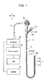
- FIG. 1 is a configuration diagram of an endoscope system of a first embodiment.
- FIG. 2 is a schematic sectional view of an endoscope in the endoscope system of the first embodiment.
- FIG. 3 is a schematic sectional view of a treatment tool in the endoscope system of the first embodiment.
- FIG. 4 is a schematic diagram of a transmission electrode and a reception electrode in the endoscope system of the first embodiment.
- FIG. 5A is a schematic sectional view of the endoscope system of the first embodiment.
- FIG. 5B is a schematic sectional view of the endoscope system of the first embodiment.
- FIG. 6A is a sectional view of the transmission electrode and the reception electrode in the endoscope system of the first embodiment.
- FIG. 6B is a sectional view of the transmission electrode and the reception electrode in the endoscope system of the first embodiment.
- FIG. 7 is an equivalent circuit diagram of the endoscope system of the first embodiment.
- FIG. 8 is an equivalent circuit diagram of an endoscope system as a variation 1 of the first embodiment.
- FIG. 9A is a schematic diagram of an electrode as a variation 2 of the endoscope system of the first embodiment.
- FIG. 9B is a schematic diagram of an electrode as the variation 2 of the endoscope system of the first embodiment.
- FIG. 9C is a schematic diagram of an electrode as the variation 2 of the endoscope system of the first embodiment.
- FIG. 9D is a schematic diagram of an electrode as the variation 2 of the endoscope system of the first embodiment.
- FIG. 9E is a schematic diagram of an electrode as the variation 2 of the endoscope system of the first embodiment.
- FIG. 9F is a schematic diagram of an electrode as the variation 2 of the endoscope system of the first embodiment.
- FIG. 9G is a schematic diagram of an electrode as the variation 2 of the endoscope system of the first embodiment.
- FIG. 9H is a schematic diagram of an electrode as the variation 2 of the endoscope system of the first embodiment.
- FIG. 9I is a schematic diagram of an electrode as the variation 2 of the endoscope system of the first embodiment.
- FIG. 10 is a schematic diagram of electrodes as the variation 2 of the endoscope system of the first embodiment.
- FIG. 11 is a schematic sectional view of the electrodes as the variation 2 of the endoscope system of the first embodiment.
- FIG. 12 is a schematic sectional view of the electrodes as the variation 2 of the endoscope system of the first embodiment.
- FIG. 13 is an equivalent circuit diagram of an endoscope system as a variation 3 of the first embodiment.
- FIG. 14A is a schematic diagram of electrodes in an endoscope system as a variation 3 of the first embodiment.
- FIG. 14B is a schematic diagram of electrodes in the endoscope system as the variation 3 of the first embodiment.
- FIG. 14C is a schematic diagram of electrodes in the endoscope system as the variation 3 of the first embodiment.
- FIG. 14D is a schematic diagram of electrodes in the endoscope system as the variation 3 of the first embodiment.
- FIG. 14E is a schematic diagram of electrodes in the endoscope system as the variation 3 of the first embodiment.
- FIG. 15 is a schematic sectional view of an endoscope in an endoscope system as a variation 4 of the first embodiment.
- FIG. 16 is a schematic sectional view of power transmission/reception units in an endoscope system as a variation 5 of the first embodiment.
- FIG. 17 is an equivalent circuit diagram of a power reception unit in an endoscope system as a variation 6 of the first embodiment.
- FIG. 18 is an equivalent circuit diagram of a power reception unit in an endoscope system of a second embodiment.
- an endoscope system 1 of the embodiment comprises a flexible endoscope (hereinafter called “endoscope”) 10 , a treatment tool 20 as a device passing through a channel 14 of the endoscope 10 , and a power source 30 .
- endoscope flexible endoscope
- treatment tool 20 as a device passing through a channel 14 of the endoscope 10
- power source 30 a power source
- the endoscope 10 comprises an endoscope insertion section 11 and an operation section 12 arranged on a base end side of the endoscope insertion section 11 , and a universal cord 13 provided to extend from the operation section 12 .
- the endoscope insertion section 11 comprises a distal end portion 11 A in which an imaging unit 15 (an image sensor such as a CCD or a CMOS) (see FIG. 2 ) is arranged, a curved portion 11 B for changing the direction of the distal end portion 11 A, and a soft portion 11 C being flexible and elongated.
- an imaging unit 15 an image sensor such as a CCD or a CMOS
- the operation section 12 is a non-flexible section grasped by an operator to perform a directional operation of the distal end portion 11 A, an air supply operation, a water supply operation, an endoscopic image taking operation, and the like.
- the endoscope insertion section 11 is a flexible section to be movably inserted from an oral cavity or an anus into an alimentary tract.
- a processor 32 as a hardware connected to the universal cord 13 of the endoscope 10 comprises a control unit (not illustrated) composed of a CPU and the like for controlling the entire endoscope system 1 to process an imaging signal output from the imaging unit 15 and display an endoscopic image on a monitor 33 .
- the power source 30 connected to the processor 32 supplies high-frequency power to the treatment tool 20 .
- a foot switch SW 31 controls ON/OFF of the output of the power source 30 .
- a line can be branched from the universal cord 13 may be connected directly to the power source 30 .
- the endoscope 10 comprises a flexible channel 14 made of a resin tube passing through the endoscope insertion section 11 from an insertion opening 14 A of the operation section 12 to an distal opening 14 B of the distal end portion 11 A.
- the treatment tool 20 comprises a distal end portion 21 A in which a treatment unit 22 is arranged, a treatment tool insertion section 21 B can be flexible and elongated, and an operation section 21 C arranged on the base end side of the treatment tool insertion section 21 B and operated by the operator outside the body.
- the treatment tool 20 is inserted from the insertion opening 14 A to pass through the channel 14 and protrude the distal end portion 21 A from the distal opening 14 B.
- the distal end portion 21 A comprises a pair of blades (electrodes) 22 A, 22 B (see FIG. 3 ) as the treatment unit 22 through which high-frequency current is passed.
- a body tissue (affected area) LT as a treated area grasped with the pair of blades 22 A, 22 B (see FIG. 3 ) of forceps according to the operation in the operation section 21 C is excised and bleeding is stopped by Joule heat generated by the high-frequency current.
- the power source 30 outputs high-frequency power, for example, with a frequency of not less than 100 kHz and not more than 100 MHz.
- the frequency of the high-frequency power is preferably selected from frequencies allowed by the laws and the like, which is 13.56 MHz, for example. It is preferred, but not particularly limited to, that the waveform amplitude of the high-frequency power be of a sinusoidal wave.
- the treatment tool 20 and the power source 30 are not connected by wire. However, when the treatment tool 20 is inserted into the channel 14 , the treatment tool 20 receives, in wireless power transmission, power required to do a treatment from the power source 30 through the endoscope 10 . Note that the wireless power transmission is the same in meaning as wireless power supply.
- the endoscope 10 comprises a power transmission unit 19 comprising a first transmission electrode 18 A and a second transmission electrode 18 B to convert the high-frequency power output from the power source 30 into an alternating electric field.
- the first transmission electrode 18 A and the second transmission electrode 18 B of the endoscope 10 are made of cylindrical conductors laid to cover the outer circumference of the channel 14 .
- the first transmission electrode 18 A and the second transmission electrode 18 B are almost identical in diameter and length to each other (e.g., ⁇ 20%) with a gap (air gap) for insulation between both.
- the channel 14 comprises a flexible tube and a branch tube, and one side of the branch tube is connected to an air sending and sucking tube 14 C.
- the power transmission unit 19 may be structured to comprise a hollow section with which part of the channel 14 is replaced as long as it is located inside of at least either of the operation section 12 and the endoscope insertion section 11 .
- a component that forms the hollow section in the above structure is also regarded as part of the channel 14 .
- the conductors of the first transmission electrode 18 A and the second transmission electrode 18 B may be exposed to the inner surface of the hollow section in terms of the function as electrodes, it is preferred that the inner surface of the hollow section be sealed by an insulating material because the channel 14 is also used for sending and sucking air, and the like.
- the treatment tool 20 comprises a power reception unit 29 comprising a first reception electrode 28 A and a second reception electrode 28 B to receive an alternating electric field.
- the first reception electrode 28 A and the second reception electrode 28 B of the treatment tool 20 are made up of cylindrical conductors laid along the outer circumferential surface of the insertion section 21 B.
- the first reception electrode 28 A is almost identical in diameter and length to the second reception electrode 28 B with a gap (air gap) for insulation between both.
- each of the first transmission electrode 18 A and the second transmission electrode 18 B is called the power transmission electrode 18
- each of the first reception electrode 28 A and the second reception electrode 28 B is called the reception electrode 28 .
- a region of part of the insertion section 21 B, where the reception electrode 28 is arranged, is so arranged that the conductor will not be exposed to the outermost circumferential surface, and if it can be inserted into the channel 14 , the outer diameter ⁇ (20) of the region may be made larger than other regions.
- the reception electrode 28 of the treatment tool 20 cannot efficiently receive an alternating electric field generated by the power transmission electrode 18 of the endoscope 10 until the treatment unit 22 protrudes from the distal opening 14 B.
- the reception electrodes 28 A and 28 B are in a state of being inserted in the transmission electrodes 18 A and 18 B, respectively. Therefore, in the endoscope system 1 , the reception electrode 28 and the power transmission electrode 18 are strongly capacitively coupled to each other in the state where the treatment unit 22 is protruding from the distal opening 14 B so that the alternating electric field generated by the power transmission electrode 18 can be received efficiently.
- the transmission electrodes 18 A and 18 B laid along the outer surface of the cylindrical channel, and the reception electrodes 28 A and 28 B laid along the outer surface of the cylindrical treatment tool are both cylindrical.
- the first transmission electrode 18 A and the first reception electrode 28 A arranged opposite to each other in a concentric fashion form a first capacitor C 1 .
- the second transmission electrode 18 B and the second reception electrode 28 B arranged opposite to each other in a concentric fashion form a second capacitor C 2 in the same manner.
- the treatment tool 20 has no physical contact (connection) with the endoscope 10 through the conductor.
- the power reception unit 29 of the treatment tool 20 is capacitively coupled to the power transmission unit 19 of the endoscope 10 .
- the high-frequency power output from the power source 30 of the endoscope 10 in the endoscope system 1 is output to the treatment unit 22 of the treatment tool 20 through the capacitors C 1 and C 2 .
- wiring for connection between the power source 30 and the second transmission electrode 18 B may be ground connection.
- the power from the power transmission unit 19 is transmitted to the power reception unit 29 capacitively coupled to supply power to the treatment tool 20 .
- the efficiency of wireless transmission through capacitive coupling is proportional to the magnitude of capacitive coupling between the power transmission electrode 18 and the reception electrode 28 , i.e. the capacitances CA and CB of the capacitors C 1 and C 2 formed by the power transmission electrode 18 and the reception electrode 28 .
- the capacitance CA of the capacitor C 1 and the capacitance CB of the capacitor C 2 are substantially the same.
- the capacitance C of the capacitor is proportional to a dielectric constant ⁇ between electrodes and a counter electrode area A, and inversely proportional to an inter-electrode distance g.
- the inner diameter ⁇ (14) of the channel 14 is larger than the outer diameter ⁇ (20) of the treatment tool insertion section 21 B so that the treatment tool insertion section 21 B of the treatment tool 20 can be inserted.
- the thickness of the channel 14 is regarded as zero, when the electrodes of the capacitors C 1 and C 2 are coaxial with each other and not eccentric, the inter-electrode distance g therebetween is very short as 0.1 mm.
- the counter electrode area A is proportional to a length L of a shorter electrode.
- the length of the power transmission electrode 18 and the reception electrode 28 be 1 cm or more. If the length is in the above range or more, power can be transmitted and received.
- the maximum length of the power transmission electrode 18 and the reception electrode 28 is determined by a length D of the channel 14 .
- the channel length D of the flexible endoscope 10 is about not less than 100 cm and not more than 230 cm.
- the maximum length of the reception electrode 28 is also about (D ⁇ )/2.
- the length of the power transmission electrode 18 and the reception electrode 28 be not less than 5 cm and not more than 100 cm in terms of the transmission/reception efficiency and the self-inductance.
- an insulating material comprising a high dielectric constant ⁇ , such as fluorocarbon resin, may be arranged between the power transmission electrode 18 and the reception electrode 28 to increase the capacitance C.
- the capacitance C may be increased by a mechanism for making the center positions of the power transmission electrode 18 and the reception electrode 28 eccentric to each other, or a mechanism for pressing the channel with the power transmission electrode 18 laid to deform to the center side or to one side in order to reduce the inter-electrode distance g locally.
- a state in which the capacitance becomes the highest with the capacitors made not eccentric is a state in which the reception electrode 28 is inserted into the entire length of the power transmission electrode 18 . Therefore, it is preferred that the length of the reception electrode 28 be longer than the length of the power transmission electrode 18 , and in light of the protrusion amount d from the distal opening 14 B of the treatment tool 20 , it is particularly preferred that the total length of the two reception electrodes 28 be (total length of the two transmission electrodes 18 +gap ⁇ +protrusion amount d). Note that the protrusion amount d is, for example, not less than 1 cm and not more than 10 cm, though it depends on the treatment tool.
- the minimum length of the power transmission electrode 18 and the like is a length at which parasitic capacitance in the circuit and capacitance involved in transmitting/receiving power, i.e. combined capacitance of the capacitance CA of the capacitor C 1 and the capacitance CB of the capacitor C 2 becomes substantially the same as each other.
- the parasitic capacitance in the circuit is higher than the capacitance involved in transmitting/receiving power, most of the supplied power does not reach the treatment unit.
- the treatment unit consumes more of the power input from the power transmission unit to the power reception unit, transmission efficiency becomes higher. Therefore, it is preferred that the load on the treatment unit, i.e., the resistance should be large compared with various resistive components in the circuit.
- the power transmission electrode 18 is arranged in the operation section 12 of the channel 14 , it may be arranged in the soft portion 11 C of the channel 14 , or arranged in the operation section 12 and the soft portion 11 C of the channel 14 . Further, the first transmission electrode 18 A may be arranged in the operation section 12 of the channel 14 and the second transmission electrode 18 B may be arranged in the soft portion 11 C of the channel 14 .
- the length of the reception electrode 28 illustrated in FIG. 3 is short, it may be, for example, an electrode having almost the same length as the length of the insertion section 21 B.
- the power transmission electrode 18 and the reception electrode 28 are only need to be arranged in positions where the electrodes are strongly capacitively coupled to each other when the treatment unit is in operation. Note that the power transmission electrode 18 and the reception electrode 28 placed inside the flexible, soft portion 11 C need to be flexible.
- the channel 14 is so used that capacitors C 1 and C 2 short in inter-electrode distance g, wide in counter electrode area A, and high in capacitance C can be formed.
- the endoscope system 1 comprising the flexible endoscope 10 comprising the flexible, elongated endoscope insertion section 11 (channel 14 ) is high in the efficiency of wireless power transmission because it can increase the length of the power transmission electrode 18 and the reception electrode 28 according to the length of the endoscope insertion section 11 .
- the length of the power transmission electrode 18 and the reception electrode 28 is easy to set the length of the power transmission electrode 18 and the reception electrode 28 to 5 cm or more, the power transmission electrode 18 and the reception electrode 28 placed inside the flexible, soft portion 11 C need to be flexible.
- the capacitors C 1 and C 2 are made up of concentric counter electrodes, even when the treatment tool 20 rotates in the channel 14 around the longitudinal direction as its axis, the power transmission electrode 18 and the reception electrode 28 are capacitively coupled stably. Thus, the operator can carry out an insertion operation without being conscious of the rotation of the treatment tool 20 .
- the power transmission electrode 18 is made of cylindrical metal laid to cover the outer circumference of the channel 14 .
- a metal film made of copper or the like is formed on the outer circumferential surface of the channel 14 as a flexible tube by an evaporation method or a plating method to enable the formation of the power transmission electrode 18 .
- the reception electrode 28 can also be made by forming a metal film on the outer circumferential surface of the treatment tool insertion section 21 B of the treatment tool 20 in the same manner as the power transmission electrode 18 . Note that it is preferred that the surfaces of the power transmission electrode 18 and the reception electrode 28 should be covered with insulating films to ensure the insulating performance and reliability.
- the power transmission electrode 18 and the reception electrode 28 made of the metal films are easy to be laid on curved surfaces, and have flexibility.
- the same treatment tool 20 can be used even for multiple endoscopes different in channel length D.
- the arrangement position of the power transmission electrode 18 should be set with reference to the distal opening 14 B.
- the center of gravity of the power transmission electrode 18 of the endoscope only needs to be arranged in a position a predetermined distance D 1 from the distal opening 14 B.
- the center of gravity means a center position in the longitudinal direction of the entire length of an electrode involved in transmitting or receiving power.
- the electrode is divided into multiple parts in the longitudinal direction, it is a center position of the entire length comprising all the parts.
- distance D 2 from the insertion opening 14 A to the power transmission electrode 18 in an endoscope comprising a longer channel length D becomes longer than that of an endoscope having a shorter channel length D.
- the multiple endoscopes can wirelessly feed power to the treatment tool 20 efficiently.
- an endoscope system comprising one endoscope and multiple treatment tools has the same effect, where the power reception unit 29 is arranged in a position capable of receiving the alternating electric field generated by the power transmission unit 19 most efficiently in a state of inserting each of the treatment tools into the channel 14 up to the operating position, respectively.
- an endoscope side circuit comprising a power source 30 and a power transmission unit 19 has no physical contact through a conductor with a treatment tool side circuit comprising a power reception unit 29 and treatment units 22 ( 22 A, 22 B) to apply current to a body tissue LT as a load section that consumes power.
- the power reception unit 29 is capacitively coupled to a non-radiative alternating electric field generated in a space near the power transmission unit 19 .
- the power is supplied to the treatment unit 22 of the treatment tool 20 through the power reception unit 29 capacitively coupled.
- the treatment tool 20 in the endoscope system 1 has no wiring (cable) connected to the power source 30 , it is easy to handle the treatment tool 20 with good operability. Further, since the power transmission unit 19 is arranged inside the endoscope 10 , a generated electromagnetic field is less likely to leak outside the endoscope 10 , and the influence of the leakage electromagnetic field on peripheral devices is small. Further, since distance between a living body as an object to be treated and the power transmitting/receiving units is ensured, the influence of heat generation is small.
- the cylindrical reception electrode 28 is coaxial with the cylindrical power transmission electrode 18 and the counter electrode area is largest among same-sized counter electrodes, the capacitance C of the capacitor is high.
- the reception electrode 28 and the transmission electrode 18 can be arranged over the entire length of the endoscope insertion section 11 of the flexible endoscope 10 , it is easy to further increase the capacitance.
- a relative positional relationship between the power transmission unit 19 and the power reception unit 29 is defined by arranging the power transmission unit 19 inside the endoscope 10 , the state of strongly capacitive coupling between the power transmission unit 19 and the power reception unit 29 , i.e., a state of high power transmission efficiency can be maintained stably, and energy saving performance is excellent as well.
- the endoscope system 1 may comprise an inductance element 17 in a power transmission/reception circuit comprising the power transmission unit 19 of the endoscope 10 and the power reception unit 29 of the treatment tool 20 .
- the addition of an inductance component causes the power transmission/reception circuit to form a serial resonance circuit with a predetermined resonant frequency F 1 .
- circuit capacitance Ctotal comprising the capacitance CA of the capacitor C 1 and the capacitance CB of the capacitor C 2
- circuit inductance Ltotal comprising the inductance element 17
- the frequency F 0 of the high-frequency power output from the power source 30 coincides with the resonant frequency F 1 of the power transmission/reception circuit. Therefore, the high-frequency power output from the power source 30 is efficiently output to the treatment unit 22 .
- the power reception unit 29 of the treatment tool 20 may comprise an inductance element, or the power transmission unit 19 and the power reception unit 29 may comprise inductance elements, respectively.
- voltage across the terminals of the inductance element in the resonance circuit is the same as the voltage across the terminals of the capacitor, and the inductance of the inductance element is set to compensate for a reactance using the capacitance of the capacitor and a specific frequency.
- the voltage across the terminals is inversely proportional to the capacitance. Therefore, the higher the capacitance of the capacitor, the lower the voltage across the terminals, and this can lead to reducing risk of insulation breakdown.
- the capacitance is too high, self-resonance may occur due to the self-inductance of the resonance circuit even without any inductance element 17 , and this can deteriorate controllability.
- the capacitance needs to be low to arrange an inductance element in order to improve controllability.
- the capacitance is set in consideration of trade-off between the risk of insulation breakdown and controllability. Since the voltage across the terminals of the inductance element is proportional to the inductance, though not described in detail, the inductance element acts in an opposite way to the capacitance element.
- a switch is used to control ON/OFF of the power output to the treatment tool 20 as already described above.
- the switch is illustrated as the foot switch 31 in FIG. 1 , but the switch may be arranged in the power source 30 , the operation section 12 of the endoscope 10 , or the operation section 21 C of the treatment tool 20 .
- the switch connected to the power source 30 or the switch arranged in the power source 30 controls ON/OFF of the output of the power source 30 .
- the switch arranged in the operation section 12 or the operation section 21 C controls ON/OFF of power through an internal circuit of the power transmission unit 19 or the power reception unit 29 .
- a Q value of the power transmission/reception circuit can be increased/decreased to make a vast change in transmission/reception efficiency in order to obtain the same effect as the ON/OFF control.
- the control of decreasing the Q value may cause a problem such as heat generation.
- the switch may be a button switch, a touch gesture-capable operating part, a speech-recognition operating part, or the like.
- the switch as power transmission starting/stopping means for starting or stopping output from the power source 30 is arranged separately from the power source 30 , or arranged in the operation section 12 of the endoscope 10 or in the treatment tool 20 .
- endoscope systems 1 A to 1 F, and the like as variations 1 to 6 of the first embodiment will be described. Since the endoscope systems 1 A to 1 F, and the like comprise the same components as the endoscope system 1 already described and are similar to the endoscope system 1 , the same reference numerals are given to components having the same functions to omit the description thereof.
- All the endoscope systems 1 A to 1 F, and the like have the effects of the endoscope system 1 , and further have more beneficial effects than the endoscope system 1 , respectively.
- an inductance element 17 A is a variable inductance element. Then, a control unit 32 A adjusts the inductance of the inductance element 17 A to make the resonant frequency F 1 of the resonance circuit coincide with the frequency F 0 of high-frequency power output from the power source 30 .
- the control unit 32 A is, for example, arranged in the processor 32 , the power source 30 , or the endoscope 10 .
- the resonant frequency F 1 of the resonance circuit varies.
- the resonant frequency F 1 is adjusted to coincide with the frequency F 0 of high-frequency power.
- control unit 32 A may control the power source 30 according to the change in the resonant frequency F 1 of the power transmission/reception circuit to change the frequency F 0 of high-frequency power or an output value of the high-frequency power.
- the inductance element 17 A is described as part of the power transmission unit 19 A, but the inductance element 17 A and the control unit 32 A may be, for example, part of the processor 32 . Further, the inductance element 17 A and the like may be arranged in the operation section 21 C of the treatment tool 20 . In other words, the inductance element 17 A and the control unit 32 A have only to be comprised in any of the components in the endoscope system 1 A.
- an impedance matching circuit may be arranged before the power transmission unit to make the impedance on the treatment unit side of the power transmission unit coincide with the output impedance of the power supply in order to suppress reflection so that the efficiency of power input from the power source 30 to the resonance circuit will be increased.
- the impedance matching circuit composed of a combination of two or more elements such as a capacitance element and an inductance element may be part of the processor 32 , or may be arranged in the operation section 21 C of the treatment tool 20 .
- the distribution of a generated alternating electric field, a capacitive coupling state, and the like greatly vary depending on the electrode structure and arrangement of the power transmitting/receiving units.
- power can be wirelessly transmitted as long as the structure is such that an alternating electric field generated in the power transmission unit 19 causes capacitive coupling to the power reception unit 29 .
- FIG. 9A to FIG. 12 illustrate electrodes as variations of the power transmission electrode 18 and the reception electrode 28 .
- the structure of the reception electrode 28 of the power reception unit 29 may be the same as or different from the power transmission electrode 18 of the power transmission unit 19 .
- An electrode 8 A in FIG. 9A is made of a metal member, made by shaping copper foil or the like into a cylinder, or of a copper tube or the like.
- An electrode 8 B in FIG. 9B is made by coupling multiple cylindrical metal members and electrically connecting the metal members. The electrode 8 B will have flexibility even if each of the cylindrical metal members has low flexibility. Since an electrode 8 C in FIG. 9C is made of a metal member formed into a mesh, it has flexibility. Since an electrode 8 D in FIG. 9D comprises a slit formed in the longitudinal direction, a reduction in eddy current loss is small.
- An electrode 8 E in FIG. 9E is divided by multiple slits, but respective pieces are electrically connected. Since the electrode 8 E is divided into multiple elongated members, it has flexibility.
- An electrode 8 F in FIG. 9F comprises a spiral form. Although adjacent element wires are in non-contact with each other in the electrode 8 F, it is preferred that the electrode 8 F be a so-called densely wound coil with adjacent element wires being in contact and conductive with each other to reduce self-inductance.
- An electrode 8 G in FIG. 9G is formed into a spiral shape comprising folded portions.
- An electrode 8 H in FIG. 9H comprises folded portions at the edges in the longitudinal direction.
- a densely wound spiral coil may be arranged in the treatment tool insertion section 21 B of the treatment tool 20 to ensure flexibility and mechanical strength.
- the reception electrode 28 can be formed by using part of a shape holding spiral coil of the treatment tool 20 , which comprises the same structure as the electrode 10 F, to reduce the size and cost of the treatment tool 20 .
- a conducting wire for energization is connected to the shape holding spiral coil so that it can be used as the reception electrode 28 .
- the shape holding spiral coil is made of stainless steel or the like comprising a relatively high electric resistance, it is preferred that a low-resistance metal material should be formed on the surface by plating with copper, silver, or the like to reduce the electric resistance.
- at least part of the stainless coil may be replaced by a coil made of a low-resistance metal material so that it will be used as the reception electrode 28 .
- an electrode 8 I illustrated in FIG. 9I is similar in structure to the electrode 8 B, each of adjacent cylindrical metal members is used as the transmission electrode 18 A or the transmission electrode 18 B, respectively. In other words, the adjacent cylindrical metal members are not connected.
- the capacitance CA of capacitor C 1 and the capacitance CB of the capacitor C 1 will be little different from each other even if the flexible channel 14 is highly deformed to change each inter-electrode distance gA between the transmission electrode 18 A and the reception electrode 28 A, and each inter-electrode distance gB between the transmission electrode 18 B and the reception electrode 28 B.
- the change in capacitance CA of the capacitor C 1 and the change in the capacitance CB of the capacitor C 2 are averaged.
- the transmission/reception efficiency is less likely to change drastically.
- the power transmission electrode 18 and the reception electrode 28 may be placed to form two pairs of capacitors C 1 and C 2 at the same position in the longitudinal direction. Compared with a case where the power transmission electrode 18 and the reception electrode 28 are arranged in the longitudinal direction, since this structure allows respective electrode lengths to be reduced to half or the maximum length of the electrode lengths to be doubled, the design freedom is high.
- the power transmission electrode 18 is divided into ten parts, i.e., transmission electrodes 18 N 1 to 18 N 10 .
- the transmission electrodes 18 N 1 to 18 N 10 are connected to the power source 30 through respective switching elements (not illustrated).
- the treatment tool 20 is rotatable inside the channel 14 .
- some of the transmission electrodes 18 N 1 to 18 N 10 are selected as being capacitively coupled most strongly to the reception electrodes 28 to form the capacitors C 1 and C 2 . It is preferred that the number of electrode divisions be not less than three and not more than ten. A predetermined effect can be obtained within the above range.
- the transmission electrodes 18 A and 18 B form a capacitor C 3 that generates an alternating electric field as a near field.
- the reception electrodes 28 A and 28 B form a capacitor C 4 , and the capacitor C 4 is capacitively coupled to the alternating electric field generated by the capacitor C 3 .
- the transmission electrode 18 A and the transmission electrode 18 B are arranged in the form of a dipole antenna.
- a power transmission unit 19 C and a power reception unit 29 C comprise inductance elements 17 C and 27 C, respectively, to form an independent resonance circuit. Then, a resonant frequency F 1 C of the power transmission unit 19 C and a resonant frequency F 2 C of the power reception unit are the same as the frequency F 0 of the high-frequency power.
- FIG. 14B to FIG. 14E illustrate structures in which dipole antenna-shaped electrodes illustrated in FIG. 14A are folded or wound.
- FIG. 14E illustrates a structure in which two electrodes paired in the longitudinal direction are wound in the shape of a double helix. Since the electrodes wound in the shape of the double helix can obtain higher capacitance than those folded or wound in the opposite directions, the transmission efficiency is high. Further, since the electric field is distributed in a wide range in the longitudinal direction, the positional degree of freedom of the treatment tool 20 is high and operability is excellent.
- an endoscope system 1 D comprising an endoscope 10 D with a shielding member 18 S arranged therein to shield an electromagnetic field as illustrated in FIG. 15 is preferable.
- the shielding member 18 S only needs to be arranged to cover at least part of the outer circumference of the power transmission electrode 18 , it is preferred that shielding member 18 S should be arranged to cover the outer circumference completely.
- a conductive material for example, a metal material such as gold, silver, copper, aluminum, or stainless steel, highly doped semiconductor, conductive resin, or the like is used.
- a soft magnetic material such as Permalloy
- the shielding member 18 S may be connected to the ground (ground-connected).
- the channel 14 is covered with the shielding member 18 S covering the power transmission unit 19 in the endoscope system 1 D.
- various bipolar treatment tools each comprising a load section operating with power received by the power reception unit 29 .
- high-frequency incision forceps high-frequency hemostatic forceps, hot biopsy forceps, a high-frequency coagulation treatment tool, an AC generating treatment tool for plasma, a heating treatment tool, a cooling treatment tool, a vibrating treatment tool, a radiation treatment tool, or the like can be used as the treatment tool 20 .
- the devices are not limited to treatment tools for applying high-frequency power to the body tissue LT to do treatments, and the devices may also be various electric-driven treatment tools.
- the endoscope system can be used for an ultrasonic treatment tool using ultrasonic vibration to make an incision in a body tissue and coagulate the body tissue, an ultrasonic suction treatment tool using ultrasonic vibration to grind and suck a body tissue, a resection treatment tool using a turning force of a drill or the like to grind a body tissue, a treatment tool with an actuator having the function of electrically driving the tips of forceps, and the like.
- the devices in the present invention comprise a probe and the like that are passed through the channel 14 but the distal end portion 21 A thereof does not protrude from the distal opening 14 B.
- a probe comprising multiple magnetism generating elements of an endoscope shape detector for detecting an endoscope insertion shape is a device of the present invention.
- Power received through wireless transmission is output to the magnetism generating elements as a load section.
- an auxiliary light probe 20 E with an LED element 22 E arranged in a distal end portion thereof in an endoscope system 1 E is also used in a state where the distal end portion 21 A does not protrude from the distal opening 14 B.
- the received power is output to the LED element 22 E as a load section.
- the sum of the total electrode length Lelec, i.e. the total length of overlapping portions between the power transmission electrode 18 and the reception electrode 28 , and a total gap ⁇ existing depending on the electrode structure is not less than 50 cm and not more than 100 cm, which is drawn to be almost the same as the length D of the channel 14 .
- the power reception unit 29 is arranged in a position capable of receiving the alternating electric field generated by the power transmission unit 19 most efficiently in a state of being inserted into the channel 14 up to the operating position, i.e., in an inserted state where the supply of power is required.
- auxiliary light probe 20 E When the auxiliary light probe 20 E is used, for example, even an endoscope having no special light observation function can irradiate, if needed, an affected area with special light of a wavelength appropriate to the affected area and generated by the auxiliary light probe 20 E to make more effective observations.
- the endoscope system should have treatment tools each with power reception efficiency corresponding to the load.
- the counter electrode area is set small for a treatment tool for which a power of 1 W is required so that the power reception efficiency of the treatment tool will be 1/100 of the power reception efficiency of a treatment tool for which a power of 100 W is required.
- the resonant frequency of the power reception unit may be set to deviate from the frequency of the alternating electric field intentionally to reduce the power reception efficiency.
- a treatment tool with lower power required for the treatment is so set that the power transmission efficiency between the power transmission unit 19 and the power reception unit 29 will be reduced.
- an endoscope system comprising multiple treatment tools, each comprising a power reception unit the power reception efficiency of which is set according to each load, does not need to adjust the output of the power source 30 according to the treatment tool 20 , the operability is good.
- high-frequency AC power received by the power reception unit 29 is used directly for a treatment through the treatment unit 22 .
- the power used for the treatment is the same as the high-frequency power output from the power source 30 , for example, a sinusoidal AC power of 13.56 MHz.
- a treatment tool 20 F in an endoscope system 1 F as a variation 6 comprises a power conversion unit 25 for converting high-frequency power received by the power reception unit 29 and outputting the covered power to the treatment unit 22 .
- the power conversion unit 25 converts the power, received by the power reception unit 29 , to power appropriate for a treatment through the treatment unit 22 .
- the treatment tool 20 F in the endoscope system 1 F may also comprise an output switching unit as a switch for switching between outputting the high-frequency power, received by the power reception unit 29 , directly to the treatment unit 22 , and outputting the high-frequency power to the power conversion unit 25 .
- the power conversion unit 25 boosts the voltage of sinusoidal, high-frequency AC power, modulates the amplitude to obtain DC power, pulse waveform power, attenuation waveform power, square-wave power, or the like, or modulates the frequency.
- the treatment tool 20 F in the endoscope system 1 F comprises the power conversion unit 25 for converting the waveform or the like of the power received by the power reception unit 29 into a waveform or the like of power to be applied by the treatment unit. Further, the treatment tool 20 F comprises the output switching unit for applying, to the treatment unit 22 , either the power received by the power reception unit 29 directly or power converted by the power conversion unit 25 .
- the endoscope system 1 F for converting the power, received by the power reception unit 29 , into power appropriate for a treatment and outputting the converted power to the treatment unit 22 can do a better treatment.
- an endoscope system 1 G of a second embodiment will be described. Since the endoscope system 1 G is similar to the endoscope systems 1 to 1 F already described, the same reference numerals are given to components having the same functions to omit the description thereof.
- a treatment tool 20 G in the endoscope system 1 G comprises a power conversion unit 25 G for converting received AC power to DC power, a power storage unit 40 for storing power output from the power conversion unit 25 G, a notice unit 41 for giving notice of a power storage state of the power storage unit 40 , and a drive unit 42 for converting the DC power stored in and output from the power storage unit 40 into power according to the specification of the treatment unit 22 .
- the power storage unit 40 is not limited to a battery such as a lithium-ion secondary battery.
- a battery such as a lithium-ion secondary battery.
- an electric double layer capacitor can be used particularly preferably as the power storage unit 40 because it can be charged and discharged rapidly with little degradation of capacity caused by charging and discharging, though the power storable capacity is smaller than the secondary battery.
- the power storage unit 40 may be composed of the secondary battery and the electric double layer capacitor.
- the notice unit 41 is an indication unit made up, for example, of an LED to indicate the amount of power storage (remaining power level) of the power storage unit 40 .
- the indication unit glows green when the amount of power storage is enough to allow a prolonged treatment, glows yellow when the amount of power storage is a bit small, and glows red when the amount of power storage is too small to do the treatment.
- the notice unit 41 may generate sound, light, vibration, or the like to notify the operator of that effect.
- the endoscope system 1 G has the effects of the endoscope system 1 and the like, and further can do a treatment in a state where the power reception unit 29 cannot receive power.
- an endoscope system comprising a primary battery can obtain the above effect, it is more preferred to comprise the power storage unit 40 without a need to exchange batteries.
- the time required for the treatment unit 22 to use power is short and intermittent. Therefore, even if the power reception unit 29 can receive only low power, the treatment tool 20 G can charge the power storage unit 40 during an interval between treatments.
- the treatment tool 20 G uses, for a treatment, power stored in the power storage unit 40 , there is no problem if the power required by the treatment unit 22 exceeds the power received by the power reception unit 29 , and a high-power treatment can be done despite the generation of a strong electric field being unnecessary.
- the power transmission unit 19 does not need to generate a strong electric field even when high power is required instantaneously. Therefore, there is no danger to cause adverse effects of a leakage electric field on peripheral devices.
- the high-frequency power output from the power source 30 can be reduced in the endoscope system 1 G, the electric field leakage from the power transmission unit 19 is reduced, and it is less likely to cause the heat generation problem or the like.
- the power received by the power reception unit 29 may be used directly for the treatment even in the endoscope system 1 G.
- endoscope systems obtained by combining the aforementioned embodiments and variations have a combination of the effects of respective endoscope systems.
- an endoscope system of one embodiment comprises: a flexible endoscope comprising a flexible insertion section comprising a distal end portion in which an imaging unit is arranged, an operation section arranged on a base end side of the insertion section, and a flexible channel that passes through the insertion section; a power supply for outputting high-frequency power; and a treatment tool with a treatment unit comprising a pair of blades for supplying power to an area to be treated, the treatment unit being inserted from an insertion opening of the operation section, passing through the channel, and protruding from an opening of the distal end portion, wherein
- the flexible endoscope comprises a power transmission unit comprising a first transmission electrode and a second transmission electrode laid along the outer circumferential surface of the channel to generate an alternating electric field by the high-frequency current input from the power supply, and
- the treatment tool comprises the treatment unit for doing a treatment with power, a power reception unit comprising a first reception electrode arranged opposite to the first transmission electrode in a concentric fashion to form a first capacitor and a second reception electrode arranged opposite to the second transmission electrode in a concentric fashion to form a second capacitor identical in length to the first capacitor in a state where the treatment unit is inserted into the channel up to an operating position to receive the alternating electric field so as to form, together with the power transmission unit, a resonance circuit comprising a resonant frequency identical to the frequency of the high-frequency power input from the power source, a power storage unit for storing power received by the power reception unit and outputting, to the treatment unit, power higher than the power received by the power reception unit, and a notice unit for giving notice of a power storage state of the power storage unit.
- a power reception unit comprising a first reception electrode arranged opposite to the first transmission electrode in a concentric fashion to form a first capacitor and a second reception electrode arranged opposite to the second transmission electrode in a
Landscapes
- Health & Medical Sciences (AREA)
- Life Sciences & Earth Sciences (AREA)
- Engineering & Computer Science (AREA)
- Surgery (AREA)
- Physics & Mathematics (AREA)
- Molecular Biology (AREA)
- Heart & Thoracic Surgery (AREA)
- Animal Behavior & Ethology (AREA)
- General Health & Medical Sciences (AREA)
- Nuclear Medicine, Radiotherapy & Molecular Imaging (AREA)
- Medical Informatics (AREA)
- Public Health (AREA)
- Veterinary Medicine (AREA)
- Biomedical Technology (AREA)
- Plasma & Fusion (AREA)
- Otolaryngology (AREA)
- Optics & Photonics (AREA)
- Biophysics (AREA)
- Radiology & Medical Imaging (AREA)
- Pathology (AREA)
- Computer Networks & Wireless Communication (AREA)
- Cardiology (AREA)
- Power Engineering (AREA)
- Astronomy & Astrophysics (AREA)
- General Physics & Mathematics (AREA)
- Surgical Instruments (AREA)
- Endoscopes (AREA)
- Instruments For Viewing The Inside Of Hollow Bodies (AREA)
Applications Claiming Priority (3)
| Application Number | Priority Date | Filing Date | Title |
|---|---|---|---|
| JP2013136760 | 2013-06-28 | ||
| JP2013-136760 | 2013-06-28 | ||
| PCT/JP2014/050804 WO2014208106A1 (ja) | 2013-06-28 | 2014-01-17 | 内視鏡システム |
Related Parent Applications (1)
| Application Number | Title | Priority Date | Filing Date |
|---|---|---|---|
| PCT/JP2014/050804 Continuation WO2014208106A1 (ja) | 2013-06-28 | 2014-01-17 | 内視鏡システム |
Publications (2)
| Publication Number | Publication Date |
|---|---|
| US20150366610A1 US20150366610A1 (en) | 2015-12-24 |
| US10016235B2 true US10016235B2 (en) | 2018-07-10 |
Family
ID=52141465
Family Applications (1)
| Application Number | Title | Priority Date | Filing Date |
|---|---|---|---|
| US14/841,014 Active 2035-02-16 US10016235B2 (en) | 2013-06-28 | 2015-08-31 | Endoscope system having first transmission and reception electrodes, second transmission and reception electrodes and electrically powered treatment device powered to perform treatment |
Country Status (5)
| Country | Link |
|---|---|
| US (1) | US10016235B2 (ja) |
| EP (1) | EP3015050A4 (ja) |
| JP (1) | JP6120963B2 (ja) |
| CN (1) | CN105358036B (ja) |
| WO (1) | WO2014208106A1 (ja) |
Families Citing this family (10)
| Publication number | Priority date | Publication date | Assignee | Title |
|---|---|---|---|---|
| JP6177095B2 (ja) * | 2013-11-08 | 2017-08-09 | オリンパス株式会社 | 処置具及び医用システム |
| JP6289091B2 (ja) * | 2013-12-26 | 2018-03-07 | オリンパス株式会社 | 硬度可変アクチュエータ |
| EP3132736A4 (en) * | 2014-04-16 | 2017-12-13 | Olympus Corporation | Endoscope and instrument |
| JP6329422B2 (ja) * | 2014-04-21 | 2018-05-23 | オリンパス株式会社 | 医療器具、挿入補助具、および医療システム |
| KR20160030672A (ko) * | 2014-09-11 | 2016-03-21 | 삼성전기주식회사 | 무선 전력 수신 장치 및 무선 전력 송수신 시스템 |
| JP6362762B2 (ja) * | 2015-02-27 | 2018-07-25 | オリンパス株式会社 | 医療用給電システム |
| US9612700B2 (en) * | 2015-07-31 | 2017-04-04 | Haier Us Appliance Solutions, Inc. | User interface assemblies and electrode assemblies having intertwined electrodes |
| JP6835850B2 (ja) * | 2015-12-29 | 2021-02-24 | コーニンクレッカ フィリップス エヌ ヴェKoninklijke Philips N.V. | 手術ロボットの制御のためのシステム、制御ユニット、及び方法 |
| WO2017209754A1 (en) * | 2016-06-02 | 2017-12-07 | GYRUS ACMI, INC. (d/b/a OLYMPUS SURGICAL TECHNOLOGIES AMERICA) | Endoscope working channel protection |
| JP7358296B2 (ja) * | 2020-05-19 | 2023-10-10 | 新光電気工業株式会社 | 非接触給電装置 |
Citations (34)
| Publication number | Priority date | Publication date | Assignee | Title |
|---|---|---|---|---|
| JPS6083633A (ja) | 1983-10-12 | 1985-05-11 | オリンパス光学工業株式会社 | 内視鏡装置 |
| JPH0354605A (ja) | 1989-07-21 | 1991-03-08 | Fanuc Ltd | 数値制御装置 |
| US5249585A (en) * | 1988-07-28 | 1993-10-05 | Bsd Medical Corporation | Urethral inserted applicator for prostate hyperthermia |
| US5342381A (en) * | 1993-02-11 | 1994-08-30 | Everest Medical Corporation | Combination bipolar scissors and forceps instrument |
| US5540685A (en) * | 1995-01-06 | 1996-07-30 | Everest Medical Corporation | Bipolar electrical scissors with metal cutting edges and shearing surfaces |
| US5817092A (en) * | 1995-11-09 | 1998-10-06 | Radio Therapeutics Corporation | Apparatus, system and method for delivering radio frequency energy to a treatment site |
| US5849020A (en) | 1997-06-30 | 1998-12-15 | Ethicon Endo-Surgery, Inc. | Inductively coupled electrosurgical instrument |
| EP0888749A1 (en) | 1997-06-30 | 1999-01-07 | Ethicon Endo-Surgery, Inc. | Capacitively coupled cordless electrosurgical instrument |
| JPH1199158A (ja) | 1997-06-30 | 1999-04-13 | Ethicon Endo Surgery Inc | 静電的に連結した電気式外科手術用トロカール |
| US5916215A (en) * | 1997-06-30 | 1999-06-29 | Ethicon Endo-Surgery, Inc. | Inductively coupled electrosurgical trocar |
| JP2000254134A (ja) | 1999-03-10 | 2000-09-19 | Olympus Optical Co Ltd | 処置装置 |
| JP2002321721A (ja) | 2001-04-20 | 2002-11-05 | Ishida Co Ltd | ラベル貼付機 |
| US20040133189A1 (en) | 2002-12-27 | 2004-07-08 | Olympus Corporation | Surgical operation apparatus and control method thereof |
| US20050049633A1 (en) * | 2003-08-08 | 2005-03-03 | Olympus Corporation | Hemostatic forceps for endoscope |
| US20050182292A1 (en) * | 2004-01-16 | 2005-08-18 | Olympus Corporation | Endoscopic surgical instrument |
| JP2005224426A (ja) | 2004-02-13 | 2005-08-25 | Olympus Corp | 内視鏡用処置具 |
| US6949068B2 (en) | 2001-05-07 | 2005-09-27 | Olympus Corporation | Endoscope shape detector |
| EP1782742A2 (en) | 2005-10-28 | 2007-05-09 | Olympus Medical Systems Corp. | Treatment tool for endoscope |
| US20080015409A1 (en) * | 2006-03-09 | 2008-01-17 | Barlow David E | Treatment device for endoscope |
| US20100179384A1 (en) * | 2008-04-25 | 2010-07-15 | Hans David Hoeg | Wirelessly Powered Medical Devices And Instruments |
| US20110018359A1 (en) | 2009-07-23 | 2011-01-27 | Sony Corporation | Noncontact power feed system, noncontact relay apparatus, noncontact power reception apparatus, and noncontact power feed method |
| US20110025132A1 (en) * | 2008-04-22 | 2011-02-03 | Olympus Corporation | Power transmission system |
| US20110218402A1 (en) * | 2008-11-18 | 2011-09-08 | Olympus Corporation | Capsule-type medical device, power supply apparatus, and power supply system |
| US20110251606A1 (en) * | 2010-04-12 | 2011-10-13 | Tyco Healthcare Group Lp | Surgical Instrument with Non-Contact Electrical Coupling |
| JP2012055697A (ja) | 2010-09-10 | 2012-03-22 | Karl Storz Imaging Inc | 回転可能結合を備えた無線カメラ接続 |
| US20120184951A1 (en) * | 2011-01-19 | 2012-07-19 | Viola Frank J | Surgical Instrument Including Inductively Coupled Accessory |
| US20120209061A1 (en) | 2009-10-23 | 2012-08-16 | Olympus Corporation | Endoscope system |
| US20120221002A1 (en) | 2011-02-28 | 2012-08-30 | Ethicon Endo-Surgery, Inc. | Electrical ablation devices and methods |
| WO2013024419A2 (en) | 2011-08-16 | 2013-02-21 | Koninklijke Philips Electronics N.V. | Transfer layer for wireless capacitive power |
| WO2013073508A1 (ja) | 2011-11-14 | 2013-05-23 | 株式会社村田製作所 | 電力伝送システム |
| JP2013121201A (ja) | 2011-12-06 | 2013-06-17 | Fuji Mach Mfg Co Ltd | プリント基板の基板構造 |
| JP2013123319A (ja) | 2011-12-12 | 2013-06-20 | Fuji Mach Mfg Co Ltd | 非接触給電装置 |
| JP2014004237A (ja) | 2012-06-26 | 2014-01-16 | Olympus Corp | 医療用無線給電システム |
| US9184595B2 (en) * | 2008-09-27 | 2015-11-10 | Witricity Corporation | Wireless energy transfer in lossy environments |
Family Cites Families (9)
| Publication number | Priority date | Publication date | Assignee | Title |
|---|---|---|---|---|
| JP2579650B2 (ja) * | 1987-11-27 | 1997-02-05 | オリンパス光学工業株式会社 | 体内用レーザ光照射装置 |
| JPH0724087Y2 (ja) * | 1989-10-02 | 1995-06-05 | 富士写真光機株式会社 | 内視鏡の処置具挿通チャンネル |
| JP2801873B2 (ja) * | 1995-09-14 | 1998-09-21 | 株式会社東芝 | 電気メス装置 |
| US6022362A (en) * | 1998-09-03 | 2000-02-08 | Rubicor Medical, Inc. | Excisional biopsy devices and methods |
| EP1339312B1 (en) * | 2000-10-10 | 2006-01-04 | Microchips, Inc. | Microchip reservoir devices using wireless transmission of power and data |
| GB0614557D0 (en) * | 2006-07-21 | 2006-08-30 | Emcision Ltd | Tissue Ablator |
| US9526407B2 (en) * | 2008-04-25 | 2016-12-27 | Karl Storz Imaging, Inc. | Wirelessly powered medical devices and instruments |
| JP5106237B2 (ja) * | 2008-05-02 | 2012-12-26 | オリンパス株式会社 | 無線給電システム |
| CN101904733B (zh) * | 2010-05-24 | 2012-06-20 | 清华大学 | 无线能量传输系统及方法 |
-
2014
- 2014-01-17 EP EP14818805.5A patent/EP3015050A4/en not_active Withdrawn
- 2014-01-17 WO PCT/JP2014/050804 patent/WO2014208106A1/ja not_active Ceased
- 2014-01-17 CN CN201480036912.2A patent/CN105358036B/zh active Active
- 2014-01-17 JP JP2015523871A patent/JP6120963B2/ja active Active
-
2015
- 2015-08-31 US US14/841,014 patent/US10016235B2/en active Active
Patent Citations (44)
| Publication number | Priority date | Publication date | Assignee | Title |
|---|---|---|---|---|
| JPS6083633A (ja) | 1983-10-12 | 1985-05-11 | オリンパス光学工業株式会社 | 内視鏡装置 |
| US5249585A (en) * | 1988-07-28 | 1993-10-05 | Bsd Medical Corporation | Urethral inserted applicator for prostate hyperthermia |
| JPH0354605A (ja) | 1989-07-21 | 1991-03-08 | Fanuc Ltd | 数値制御装置 |
| US5342381A (en) * | 1993-02-11 | 1994-08-30 | Everest Medical Corporation | Combination bipolar scissors and forceps instrument |
| US5540685A (en) * | 1995-01-06 | 1996-07-30 | Everest Medical Corporation | Bipolar electrical scissors with metal cutting edges and shearing surfaces |
| US5817092A (en) * | 1995-11-09 | 1998-10-06 | Radio Therapeutics Corporation | Apparatus, system and method for delivering radio frequency energy to a treatment site |
| US5916215A (en) * | 1997-06-30 | 1999-06-29 | Ethicon Endo-Surgery, Inc. | Inductively coupled electrosurgical trocar |
| JPH1199158A (ja) | 1997-06-30 | 1999-04-13 | Ethicon Endo Surgery Inc | 静電的に連結した電気式外科手術用トロカール |
| JPH11128242A (ja) | 1997-06-30 | 1999-05-18 | Ethicon Endo Surgery Inc | 誘導結合型電気式外科手術用器具 |
| US5849020A (en) | 1997-06-30 | 1998-12-15 | Ethicon Endo-Surgery, Inc. | Inductively coupled electrosurgical instrument |
| US6187002B1 (en) | 1997-06-30 | 2001-02-13 | Ethicon Endo-Surgery, Inc. | Capacitive electrosurgical trocar including adapater |
| US6206875B1 (en) | 1997-06-30 | 2001-03-27 | Ethicon Endo-Surgery, Inc. | Method of capactively coupling energy to an electrosurgical instrument |
| EP0888749A1 (en) | 1997-06-30 | 1999-01-07 | Ethicon Endo-Surgery, Inc. | Capacitively coupled cordless electrosurgical instrument |
| JP2000254134A (ja) | 1999-03-10 | 2000-09-19 | Olympus Optical Co Ltd | 処置装置 |
| JP2002321721A (ja) | 2001-04-20 | 2002-11-05 | Ishida Co Ltd | ラベル貼付機 |
| US6949068B2 (en) | 2001-05-07 | 2005-09-27 | Olympus Corporation | Endoscope shape detector |
| US20040133189A1 (en) | 2002-12-27 | 2004-07-08 | Olympus Corporation | Surgical operation apparatus and control method thereof |
| JP2004208922A (ja) | 2002-12-27 | 2004-07-29 | Olympus Corp | 医療装置及び医療用マニピュレータ並びに医療装置の制御方法 |
| US20050049633A1 (en) * | 2003-08-08 | 2005-03-03 | Olympus Corporation | Hemostatic forceps for endoscope |
| US20050182292A1 (en) * | 2004-01-16 | 2005-08-18 | Olympus Corporation | Endoscopic surgical instrument |
| JP2005224426A (ja) | 2004-02-13 | 2005-08-25 | Olympus Corp | 内視鏡用処置具 |
| EP1782742A2 (en) | 2005-10-28 | 2007-05-09 | Olympus Medical Systems Corp. | Treatment tool for endoscope |
| US7824407B2 (en) | 2005-10-28 | 2010-11-02 | Olympus Corporation | Treatment tool for endoscope |
| US20080015409A1 (en) * | 2006-03-09 | 2008-01-17 | Barlow David E | Treatment device for endoscope |
| US20110025132A1 (en) * | 2008-04-22 | 2011-02-03 | Olympus Corporation | Power transmission system |
| US20100179384A1 (en) * | 2008-04-25 | 2010-07-15 | Hans David Hoeg | Wirelessly Powered Medical Devices And Instruments |
| US9184595B2 (en) * | 2008-09-27 | 2015-11-10 | Witricity Corporation | Wireless energy transfer in lossy environments |
| US20110218402A1 (en) * | 2008-11-18 | 2011-09-08 | Olympus Corporation | Capsule-type medical device, power supply apparatus, and power supply system |
| US20110018359A1 (en) | 2009-07-23 | 2011-01-27 | Sony Corporation | Noncontact power feed system, noncontact relay apparatus, noncontact power reception apparatus, and noncontact power feed method |
| JP2011030317A (ja) | 2009-07-23 | 2011-02-10 | Sony Corp | 非接触給電システム、非接触中継装置、非接触受電装置および非接触給電方法 |
| US20120209061A1 (en) | 2009-10-23 | 2012-08-16 | Olympus Corporation | Endoscope system |
| US20110251606A1 (en) * | 2010-04-12 | 2011-10-13 | Tyco Healthcare Group Lp | Surgical Instrument with Non-Contact Electrical Coupling |
| JP2012055697A (ja) | 2010-09-10 | 2012-03-22 | Karl Storz Imaging Inc | 回転可能結合を備えた無線カメラ接続 |
| US20120184951A1 (en) * | 2011-01-19 | 2012-07-19 | Viola Frank J | Surgical Instrument Including Inductively Coupled Accessory |
| US20120221002A1 (en) | 2011-02-28 | 2012-08-30 | Ethicon Endo-Surgery, Inc. | Electrical ablation devices and methods |
| WO2013024419A2 (en) | 2011-08-16 | 2013-02-21 | Koninklijke Philips Electronics N.V. | Transfer layer for wireless capacitive power |
| EP2782214A1 (en) | 2011-11-14 | 2014-09-24 | Murata Manufacturing Co., Ltd. | Power transmission system |
| WO2013073508A1 (ja) | 2011-11-14 | 2013-05-23 | 株式会社村田製作所 | 電力伝送システム |
| JP2013121201A (ja) | 2011-12-06 | 2013-06-17 | Fuji Mach Mfg Co Ltd | プリント基板の基板構造 |
| JP2013123319A (ja) | 2011-12-12 | 2013-06-20 | Fuji Mach Mfg Co Ltd | 非接触給電装置 |
| JP2014004237A (ja) | 2012-06-26 | 2014-01-16 | Olympus Corp | 医療用無線給電システム |
| CN104321029A (zh) | 2012-06-26 | 2015-01-28 | 奥林巴斯株式会社 | 医疗用无线给电系统 |
| US20150057653A1 (en) | 2012-06-26 | 2015-02-26 | Olympus Corporation | Medical wireless power supply system |
| EP2865348A1 (en) | 2012-06-26 | 2015-04-29 | Olympus Corporation | Medical wireless power supply system |
Non-Patent Citations (5)
| Title |
|---|
| Extended Supplementary European Search Report dated Feb. 3, 2017 in European Patent Application No. 14 81 8805.5. |
| Harakawa, Kenichi et al., "Possibility of Wireless Power Supply by Electric Coupling Technology", Takenaka Technical Research Report, No. 66, 2010, pp. 1-8, with English abstract. |
| International Search Report dated Aug. 6, 2013 issued in PCT/JP2013/066735. |
| International Search Report dated Feb. 10, 2014 issued in PCT/JP2014/050804. |
| Written Opinion of the International Searching Authority dated Aug. 6, 2013 issued in PCT/JP2013/066735. |
Also Published As
| Publication number | Publication date |
|---|---|
| EP3015050A4 (en) | 2017-03-08 |
| WO2014208106A1 (ja) | 2014-12-31 |
| CN105358036B (zh) | 2017-09-19 |
| US20150366610A1 (en) | 2015-12-24 |
| JPWO2014208106A1 (ja) | 2017-02-23 |
| EP3015050A1 (en) | 2016-05-04 |
| CN105358036A (zh) | 2016-02-24 |
| JP6120963B2 (ja) | 2017-04-26 |
Similar Documents
| Publication | Publication Date | Title |
|---|---|---|
| US10016235B2 (en) | Endoscope system having first transmission and reception electrodes, second transmission and reception electrodes and electrically powered treatment device powered to perform treatment | |
| US9833124B2 (en) | Treatment tool and endoscope system with inductance elements to power treatment device of treatment tool | |
| US9826888B2 (en) | Endoscope having power transmission electrode and treatment tool having power reception electrode, and endoscope system | |
| US10321901B2 (en) | Medical instrument that wirelessly receives power, insertion assisting tool that wirelessly transmits power and medical system | |
| JP7050305B2 (ja) | マイクロ波源が組み込まれた電気外科装置 | |
| JP2013034871A (ja) | 電気外科用高周波エネルギー伝達媒体 | |
| KR20160067112A (ko) | 비-공진 불균형 손실 전송 라인 구조물로부터 마이크로파 에너지를 전달하는 전기 수술 겸자 | |
| US20160242845A1 (en) | Treatment device and medical system | |
| JP6274960B2 (ja) | 内視鏡システム | |
| JP2015123117A (ja) | 医療用無線給電システム | |
| US20160183773A1 (en) | Treatment device and surgical system | |
| US20220378504A1 (en) | Electricity supplier | |
| CN102860869A (zh) | 一种针状双极手术电极装置及方法 | |
| CN104321029A (zh) | 医疗用无线给电系统 |
Legal Events
| Date | Code | Title | Description |
|---|---|---|---|
| AS | Assignment |
Owner name: OLYMPUS CORPORATION, JAPAN Free format text: ASSIGNMENT OF ASSIGNORS INTEREST;ASSIGNORS:TSURUTA, SHOEI;SUGIYAMA, YUTA;MATSUI, AKIRA;REEL/FRAME:036653/0044 Effective date: 20150818 |
|
| AS | Assignment |
Owner name: OLYMPUS CORPORATION, JAPAN Free format text: CHANGE OF ADDRESS;ASSIGNOR:OLYMPUS CORPORATION;REEL/FRAME:043076/0827 Effective date: 20160401 |
|
| STCF | Information on status: patent grant |
Free format text: PATENTED CASE |
|
| MAFP | Maintenance fee payment |
Free format text: PAYMENT OF MAINTENANCE FEE, 4TH YEAR, LARGE ENTITY (ORIGINAL EVENT CODE: M1551); ENTITY STATUS OF PATENT OWNER: LARGE ENTITY Year of fee payment: 4 |
|
| FEPP | Fee payment procedure |
Free format text: MAINTENANCE FEE REMINDER MAILED (ORIGINAL EVENT CODE: REM.); ENTITY STATUS OF PATENT OWNER: LARGE ENTITY |