JP7586876B2 - コネクタ - Google Patents
コネクタ Download PDFInfo
- Publication number
- JP7586876B2 JP7586876B2 JP2022164072A JP2022164072A JP7586876B2 JP 7586876 B2 JP7586876 B2 JP 7586876B2 JP 2022164072 A JP2022164072 A JP 2022164072A JP 2022164072 A JP2022164072 A JP 2022164072A JP 7586876 B2 JP7586876 B2 JP 7586876B2
- Authority
- JP
- Japan
- Prior art keywords
- tab
- terminal
- housing
- connector
- locking
- Prior art date
- Legal status (The legal status is an assumption and is not a legal conclusion. Google has not performed a legal analysis and makes no representation as to the accuracy of the status listed.)
- Active
Links
Images


Classifications
-
- H—ELECTRICITY
- H01—ELECTRIC ELEMENTS
- H01R—ELECTRICALLY-CONDUCTIVE CONNECTIONS; STRUCTURAL ASSOCIATIONS OF A PLURALITY OF MUTUALLY-INSULATED ELECTRICAL CONNECTING ELEMENTS; COUPLING DEVICES; CURRENT COLLECTORS
- H01R11/00—Individual connecting elements providing two or more spaced connecting locations for conductive members which are, or may be, thereby interconnected, e.g. end pieces for wires or cables supported by the wire or cable and having means for facilitating electrical connection to some other wire, terminal, or conductive member, blocks of binding posts
- H01R11/11—End pieces or tapping pieces for wires, supported by the wire and for facilitating electrical connection to some other wire, terminal or conductive member
-
- H—ELECTRICITY
- H01—ELECTRIC ELEMENTS
- H01R—ELECTRICALLY-CONDUCTIVE CONNECTIONS; STRUCTURAL ASSOCIATIONS OF A PLURALITY OF MUTUALLY-INSULATED ELECTRICAL CONNECTING ELEMENTS; COUPLING DEVICES; CURRENT COLLECTORS
- H01R13/00—Details of coupling devices of the kinds covered by groups H01R12/70 or H01R24/00 - H01R33/00
- H01R13/40—Securing contact members in or to a base or case; Insulating of contact members
- H01R13/405—Securing in non-demountable manner, e.g. moulding, riveting
- H01R13/41—Securing in non-demountable manner, e.g. moulding, riveting by frictional grip in grommet, panel or base
-
- H—ELECTRICITY
- H01—ELECTRIC ELEMENTS
- H01R—ELECTRICALLY-CONDUCTIVE CONNECTIONS; STRUCTURAL ASSOCIATIONS OF A PLURALITY OF MUTUALLY-INSULATED ELECTRICAL CONNECTING ELEMENTS; COUPLING DEVICES; CURRENT COLLECTORS
- H01R13/00—Details of coupling devices of the kinds covered by groups H01R12/70 or H01R24/00 - H01R33/00
- H01R13/40—Securing contact members in or to a base or case; Insulating of contact members
- H01R13/42—Securing in a demountable manner
- H01R13/428—Securing in a demountable manner by resilient locking means on the contact members; by locking means on resilient contact members
-
- H—ELECTRICITY
- H01—ELECTRIC ELEMENTS
- H01R—ELECTRICALLY-CONDUCTIVE CONNECTIONS; STRUCTURAL ASSOCIATIONS OF A PLURALITY OF MUTUALLY-INSULATED ELECTRICAL CONNECTING ELEMENTS; COUPLING DEVICES; CURRENT COLLECTORS
- H01R13/00—Details of coupling devices of the kinds covered by groups H01R12/70 or H01R24/00 - H01R33/00
- H01R13/02—Contact members
- H01R13/04—Pins or blades for co-operation with sockets
- H01R13/05—Resilient pins or blades
- H01R13/055—Resilient pins or blades co-operating with sockets having a rectangular transverse section
-
- H—ELECTRICITY
- H01—ELECTRIC ELEMENTS
- H01R—ELECTRICALLY-CONDUCTIVE CONNECTIONS; STRUCTURAL ASSOCIATIONS OF A PLURALITY OF MUTUALLY-INSULATED ELECTRICAL CONNECTING ELEMENTS; COUPLING DEVICES; CURRENT COLLECTORS
- H01R4/00—Electrically-conductive connections between two or more conductive members in direct contact, i.e. touching one another; Means for effecting or maintaining such contact; Electrically-conductive connections having two or more spaced connecting locations for conductors and using contact members penetrating insulation
- H01R4/28—Clamped connections, spring connections
- H01R4/30—Clamped connections, spring connections utilising a screw or nut clamping member
-
- H—ELECTRICITY
- H01—ELECTRIC ELEMENTS
- H01R—ELECTRICALLY-CONDUCTIVE CONNECTIONS; STRUCTURAL ASSOCIATIONS OF A PLURALITY OF MUTUALLY-INSULATED ELECTRICAL CONNECTING ELEMENTS; COUPLING DEVICES; CURRENT COLLECTORS
- H01R4/00—Electrically-conductive connections between two or more conductive members in direct contact, i.e. touching one another; Means for effecting or maintaining such contact; Electrically-conductive connections having two or more spaced connecting locations for conductors and using contact members penetrating insulation
- H01R4/58—Electrically-conductive connections between two or more conductive members in direct contact, i.e. touching one another; Means for effecting or maintaining such contact; Electrically-conductive connections having two or more spaced connecting locations for conductors and using contact members penetrating insulation characterised by the form or material of the contacting members
- H01R4/64—Connections between or with conductive parts having primarily a non-electric function, e.g. frame, casing, rail
-
- H—ELECTRICITY
- H01—ELECTRIC ELEMENTS
- H01R—ELECTRICALLY-CONDUCTIVE CONNECTIONS; STRUCTURAL ASSOCIATIONS OF A PLURALITY OF MUTUALLY-INSULATED ELECTRICAL CONNECTING ELEMENTS; COUPLING DEVICES; CURRENT COLLECTORS
- H01R4/00—Electrically-conductive connections between two or more conductive members in direct contact, i.e. touching one another; Means for effecting or maintaining such contact; Electrically-conductive connections having two or more spaced connecting locations for conductors and using contact members penetrating insulation
- H01R4/58—Electrically-conductive connections between two or more conductive members in direct contact, i.e. touching one another; Means for effecting or maintaining such contact; Electrically-conductive connections having two or more spaced connecting locations for conductors and using contact members penetrating insulation characterised by the form or material of the contacting members
- H01R4/66—Connections with the terrestrial mass, e.g. earth plate, earth pin
-
- H—ELECTRICITY
- H01—ELECTRIC ELEMENTS
- H01R—ELECTRICALLY-CONDUCTIVE CONNECTIONS; STRUCTURAL ASSOCIATIONS OF A PLURALITY OF MUTUALLY-INSULATED ELECTRICAL CONNECTING ELEMENTS; COUPLING DEVICES; CURRENT COLLECTORS
- H01R13/00—Details of coupling devices of the kinds covered by groups H01R12/70 or H01R24/00 - H01R33/00
- H01R13/02—Contact members
- H01R13/10—Sockets for co-operation with pins or blades
- H01R13/11—Resilient sockets
- H01R13/113—Resilient sockets co-operating with pins or blades having a rectangular transverse section
-
- H—ELECTRICITY
- H01—ELECTRIC ELEMENTS
- H01R—ELECTRICALLY-CONDUCTIVE CONNECTIONS; STRUCTURAL ASSOCIATIONS OF A PLURALITY OF MUTUALLY-INSULATED ELECTRICAL CONNECTING ELEMENTS; COUPLING DEVICES; CURRENT COLLECTORS
- H01R2201/00—Connectors or connections adapted for particular applications
- H01R2201/26—Connectors or connections adapted for particular applications for vehicles
-
- H—ELECTRICITY
- H01—ELECTRIC ELEMENTS
- H01R—ELECTRICALLY-CONDUCTIVE CONNECTIONS; STRUCTURAL ASSOCIATIONS OF A PLURALITY OF MUTUALLY-INSULATED ELECTRICAL CONNECTING ELEMENTS; COUPLING DEVICES; CURRENT COLLECTORS
- H01R4/00—Electrically-conductive connections between two or more conductive members in direct contact, i.e. touching one another; Means for effecting or maintaining such contact; Electrically-conductive connections having two or more spaced connecting locations for conductors and using contact members penetrating insulation
- H01R4/10—Electrically-conductive connections between two or more conductive members in direct contact, i.e. touching one another; Means for effecting or maintaining such contact; Electrically-conductive connections having two or more spaced connecting locations for conductors and using contact members penetrating insulation effected solely by twisting, wrapping, bending, crimping, or other permanent deformation
- H01R4/18—Electrically-conductive connections between two or more conductive members in direct contact, i.e. touching one another; Means for effecting or maintaining such contact; Electrically-conductive connections having two or more spaced connecting locations for conductors and using contact members penetrating insulation effected solely by twisting, wrapping, bending, crimping, or other permanent deformation by crimping
- H01R4/183—Electrically-conductive connections between two or more conductive members in direct contact, i.e. touching one another; Means for effecting or maintaining such contact; Electrically-conductive connections having two or more spaced connecting locations for conductors and using contact members penetrating insulation effected solely by twisting, wrapping, bending, crimping, or other permanent deformation by crimping for cylindrical elongated bodies, e.g. cables having circular cross-section
- H01R4/184—Electrically-conductive connections between two or more conductive members in direct contact, i.e. touching one another; Means for effecting or maintaining such contact; Electrically-conductive connections having two or more spaced connecting locations for conductors and using contact members penetrating insulation effected solely by twisting, wrapping, bending, crimping, or other permanent deformation by crimping for cylindrical elongated bodies, e.g. cables having circular cross-section comprising a U-shaped wire-receiving portion
- H01R4/185—Electrically-conductive connections between two or more conductive members in direct contact, i.e. touching one another; Means for effecting or maintaining such contact; Electrically-conductive connections having two or more spaced connecting locations for conductors and using contact members penetrating insulation effected solely by twisting, wrapping, bending, crimping, or other permanent deformation by crimping for cylindrical elongated bodies, e.g. cables having circular cross-section comprising a U-shaped wire-receiving portion combined with a U-shaped insulation-receiving portion
Landscapes
- Connector Housings Or Holding Contact Members (AREA)
- Connections By Means Of Piercing Elements, Nuts, Or Screws (AREA)
Description
前記複数のタブ部が収容される複数の収容室を有し、前記端子金具が収容される、ハウジングと、
前記収容室に収容されて前記複数のタブ部の各々に電気的に接続される相手側端子と、前記相手側端子が取り付けられる電線と、を有する複数の端子付き電線と、
を備える、コネクタであって、
前記端子金具は、
前記所定方向における前記タブ連設部の一端から途中位置までに位置する少なくとも一つの前記タブ部の各々が有する第1係止部と、前記途中位置から前記所定方向における前記タブ連設部の他端までに位置する少なくとも一つの前記タブ部の各々が有する第2係止部と、を有し、
前記第1係止部によって前記タブ部を前記収容室に保持する保持力は、前記第2係止部によって前記タブ部を前記収容室に保持する保持力よりも大きく、
前記相手側端子は、
前記タブ部が挿入される筒状の箱部と、前記箱部の前記他端側の側壁に設けられて前記タブ部が前記所定方向に通過可能な広さを有する開口部と、を有する、
コネクタであること。
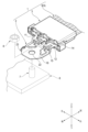
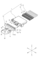
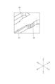
以下、図面を参照しながら、本発明の実施形態に係るコネクタ1について説明する。以下、説明の便宜上、図1~図11に示すように、「前」、「後」、「左」、「右」、「上」及び「下」を定義する。「前後方向」、「左右方向」及び「上下方向」は、互いに直交している。前後方向は、端子金具2のハウジング3への取付方向(図2参照)、及び、電線5の端末に接続された相手側端子4のハウジング3への挿入方向(図2参照)と、一致している。
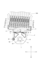
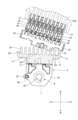
以上説明したように、本実施形態に係るコネクタ1は、アースポイント6(自動車の車体フレーム等)に固定された状態で使用される。コネクタ1が固定されたアースポイント6を有する自動車の解体作業が行われる際、コネクタ1がアースポイント6に固定された状態のまま、図9に白矢印で示すように、作業者等が、複数の端子付き電線9の電線5を一括してハウジングから離れる向き(前向き)に引く。この結果、複数の相手側端子4を介してハウジング3にその向きの外力が及ぶ。上述したように、第1係止突起24によりタブ部18,21を収容室31,32に保持する保持力が第2係止突起25によりタブ部18,21を収容室31,32に保持する保持力よりも大きい。このため、相対的に保持力が劣る第2係止突起25が、第1係止突起24よりも先にハウジング3から分離し易い。更に、相対的に保持力が劣る第2係止突起25は、第1係止突起24よりもタブ連設部17,19の相対的に左側に位置する(図3も参照)。そのため、まず、タブ連設部17,19の左端側のタブ部18,21がハウジング3から分離することで、ハウジング3の左側がアースポイント6に固定されている端子金具2に対して端子金具2から離れる向き(前向き)に移動するように、ハウジング3全体が(上方からみて時計回りに)僅かに傾斜する。
なお、本発明は上記各実施形態に限定されることはなく、本発明の範囲内において種々の変形例を採用できる。例えば、本発明は、上述した実施形態に限定されるものではなく、適宜、変形、改良、等が可能である。その他、上述した実施形態における各構成要素の材質、形状、寸法、数、配置箇所、等は本発明を達成できるものであれば任意であり、限定されない。
複数のタブ部(18,21)が間隔をあけて所定方向に並ぶようにタブ連設部(17,19)から延出した端子部(12,14)と、前記タブ連設部(17,19)に繋がり且つ外部端子(6)に接続されることになる接点部(16)と、を備え、前記端子部(12,14)及び前記接点部(16)が一繋がりの導体板から構成される、端子金具(2)と、
前記複数の前記タブ部(18,21)が収容される複数の収容室(31,32)を有し、前記端子金具(2)が収容されるハウジング(3)と、
前記収容室(31,32)に収容されて前記複数の前記タブ部(18,21)の各々に電気的に接続される相手側端子(4)と、前記相手側端子(4)が取り付けられる電線(5)と、を有する複数の端子付き電線(9)と、
を備える、コネクタ(1)であって、
前記端子金具(2)は、
前記所定方向における前記タブ連設部(17,19)の一端から途中位置までに位置する少なくとも一つの前記タブ部(18,21)の各々が有する第1係止部(24)と、前記途中位置から前記所定方向における前記タブ連設部(17,19)の他端までに位置する少なくとも一つの前記タブ部(18,21)の各々が有する第2係止部(25)と、を有し、
前記第1係止部(24)によって前記タブ部(18,21)を前記収容室(31,32)に保持する保持力は、前記第2係止部(25)によって前記タブ部(18,21)を前記収容室(31,32)に保持する保持力よりも大きく、
前記相手側端子(4)は、
前記タブ部(18,21)が挿入される筒状の箱部(41)と、前記箱部(41)の前記他端側の側壁に設けられて前記タブ部(18,21)が前記所定方向に通過可能な広さを有する開口部(44)と、を有する、
コネクタ(1)。
上記[1]に記載のコネクタ(1)において、
前記第1係止部(24)は、
前記タブ部(18,21)から前記導体板の板面方向に突出し且つ前記導体板の厚さ方向に延びる突起形状を有し、
前記第2係止部(25)は、
前記タブ部(18,21)から前記導体板の板面方向に突出し且つ前記導体板の厚さ方向に延びる突起形状を有し、
前記第1係止部(24)の前記厚さ方向における厚さが、前記第2係止部(25)の前記厚さ方向における厚さよりも大きい、
コネクタ(1)。
上記[2]に記載のコネクタ(1)において、
前記第1係止部(24)を有する前記タブ部(18,21)の数が、前記第2係止部(25)を有する前記タブ部(18,21)の数よりも多い、
コネクタ(1)。
上記[1]に記載のコネクタ(1)において、
前記端子金具(2)は、
前記第1係止部(24)及び前記第2係止部(25)の何れも有さない前記タブ部(18,21)を有する、
コネクタ(1)。
2 端子金具
3 ハウジング
4 相手側端子
5 電線
6 アースポイント(外部端子)
9 端子付き電線
12 第1端子部(端子部)
14 第2端子部(端子部)
16 固定部(接点部)
17 第1タブ連設部(タブ連設部)
18 第1タブ部(タブ部)
19 第2タブ連設部(タブ連設部)
21 第2タブ部(タブ部)
24 第1係止突起(第1係止部)
25 第2係止突起(第2係止部)
31 第1収容室(収容室)
32 第2収容室(収容室)
41 箱部
44 開口部
Claims (4)
- 複数のタブ部が間隔をあけて所定方向に並ぶようにタブ連設部から延出した端子部と、前記タブ連設部に繋がり且つ外部端子に接続されることになる接点部と、を備え、前記端子部及び前記接点部が一繋がりの導体板から構成される、端子金具と、
前記複数のタブ部が収容される複数の収容室を有し、前記端子金具が収容される、ハウジングと、
前記収容室に収容されて前記複数のタブ部の各々に電気的に接続される相手側端子と、前記相手側端子が取り付けられる電線と、を有する複数の端子付き電線と、
を備える、コネクタであって、
前記端子金具は、
前記所定方向における前記タブ連設部の一端から途中位置までに位置する少なくとも一つの前記タブ部の各々が有する第1係止部と、前記途中位置から前記所定方向における前記タブ連設部の他端までに位置する少なくとも一つの前記タブ部の各々が有する第2係止部と、を有し、
前記第1係止部によって前記タブ部を前記収容室に保持する保持力は、前記第2係止部によって前記タブ部を前記収容室に保持する保持力よりも大きく、
前記相手側端子は、
前記タブ部が挿入される筒状の箱部と、前記箱部の前記他端側の側壁に設けられて前記タブ部が前記所定方向に通過可能な広さを有する開口部と、を有する、
コネクタ。 - 請求項1に記載のコネクタにおいて、
前記第1係止部は、
前記タブ部から前記導体板の板面方向に突出し且つ前記導体板の厚さ方向に延びる突起形状を有し、
前記第2係止部は、
前記タブ部から前記導体板の板面方向に突出し且つ前記導体板の厚さ方向に延びる突起形状を有し、
前記第1係止部の前記厚さ方向における厚さが、前記第2係止部の前記厚さ方向における厚さよりも大きい、
コネクタ。 - 請求項2に記載のコネクタにおいて、
前記第1係止部を有する前記タブ部の数が、前記第2係止部を有する前記タブ部の数よりも多い、
コネクタ。 - 請求項1に記載のコネクタにおいて、
前記端子金具は、
前記第1係止部及び前記第2係止部の何れも有さない前記タブ部を有する、
コネクタ。
Priority Applications (3)
| Application Number | Priority Date | Filing Date | Title |
|---|---|---|---|
| JP2022164072A JP7586876B2 (ja) | 2022-10-12 | 2022-10-12 | コネクタ |
| US18/470,853 US12470006B2 (en) | 2022-10-12 | 2023-09-20 | Connector with a terminal fitting |
| CN202311214008.3A CN117878629A (zh) | 2022-10-12 | 2023-09-20 | 连接器 |
Applications Claiming Priority (1)
| Application Number | Priority Date | Filing Date | Title |
|---|---|---|---|
| JP2022164072A JP7586876B2 (ja) | 2022-10-12 | 2022-10-12 | コネクタ |
Publications (2)
| Publication Number | Publication Date |
|---|---|
| JP2024057375A JP2024057375A (ja) | 2024-04-24 |
| JP7586876B2 true JP7586876B2 (ja) | 2024-11-19 |
Family
ID=90581732
Family Applications (1)
| Application Number | Title | Priority Date | Filing Date |
|---|---|---|---|
| JP2022164072A Active JP7586876B2 (ja) | 2022-10-12 | 2022-10-12 | コネクタ |
Country Status (3)
| Country | Link |
|---|---|
| US (1) | US12470006B2 (ja) |
| JP (1) | JP7586876B2 (ja) |
| CN (1) | CN117878629A (ja) |
Citations (4)
| Publication number | Priority date | Publication date | Assignee | Title |
|---|---|---|---|---|
| JP2005353361A (ja) | 2004-06-09 | 2005-12-22 | Sumitomo Wiring Syst Ltd | コネクタ |
| JP2012084406A (ja) | 2010-10-12 | 2012-04-26 | Yazaki Corp | コネクタ |
| JP2013073911A (ja) | 2011-09-29 | 2013-04-22 | Auto Network Gijutsu Kenkyusho:Kk | ジョイントコネクタ |
| JP2014049329A (ja) | 2012-08-31 | 2014-03-17 | Yazaki Corp | 圧入端子及び端子圧入構造 |
Family Cites Families (6)
| Publication number | Priority date | Publication date | Assignee | Title |
|---|---|---|---|---|
| JPH021823Y2 (ja) * | 1985-02-27 | 1990-01-17 | ||
| JPH081572Y2 (ja) * | 1991-03-28 | 1996-01-17 | 矢崎総業株式会社 | プリント基板用コネクタ |
| US9362665B2 (en) | 2011-09-29 | 2016-06-07 | Autonetworks Technologies, Ltd. | Joint connector with pairs of locking lances and communication space extending between the pairs of locking lances |
| JP6422908B2 (ja) * | 2016-03-15 | 2018-11-14 | 矢崎総業株式会社 | コネクタ |
| JP6898380B2 (ja) * | 2019-04-04 | 2021-07-07 | 矢崎総業株式会社 | コネクタ |
| JP2022042037A (ja) * | 2020-09-02 | 2022-03-14 | 矢崎総業株式会社 | コネクタ |
-
2022
- 2022-10-12 JP JP2022164072A patent/JP7586876B2/ja active Active
-
2023
- 2023-09-20 CN CN202311214008.3A patent/CN117878629A/zh active Pending
- 2023-09-20 US US18/470,853 patent/US12470006B2/en active Active
Patent Citations (4)
| Publication number | Priority date | Publication date | Assignee | Title |
|---|---|---|---|---|
| JP2005353361A (ja) | 2004-06-09 | 2005-12-22 | Sumitomo Wiring Syst Ltd | コネクタ |
| JP2012084406A (ja) | 2010-10-12 | 2012-04-26 | Yazaki Corp | コネクタ |
| JP2013073911A (ja) | 2011-09-29 | 2013-04-22 | Auto Network Gijutsu Kenkyusho:Kk | ジョイントコネクタ |
| JP2014049329A (ja) | 2012-08-31 | 2014-03-17 | Yazaki Corp | 圧入端子及び端子圧入構造 |
Also Published As
| Publication number | Publication date |
|---|---|
| CN117878629A (zh) | 2024-04-12 |
| JP2024057375A (ja) | 2024-04-24 |
| US12470006B2 (en) | 2025-11-11 |
| US20240128675A1 (en) | 2024-04-18 |
Similar Documents
| Publication | Publication Date | Title |
|---|---|---|
| JP5563241B2 (ja) | 電気コネクタ | |
| US9912106B2 (en) | Electrical connector having improved shielding shell | |
| JP6493611B1 (ja) | 電気コネクタ | |
| JP2622888B2 (ja) | 電気コネクタ | |
| JP5534350B2 (ja) | コネクタ装置 | |
| JP7363626B2 (ja) | コネクタおよびコネクタ装置 | |
| US6942504B2 (en) | Connector | |
| JP7100073B2 (ja) | 電気接続部品 | |
| US20180131117A1 (en) | Joint connector | |
| US5564953A (en) | Divided-type multi-pole connector | |
| KR102503963B1 (ko) | 전기 접속 부품 | |
| JP7586876B2 (ja) | コネクタ | |
| JP7236034B2 (ja) | 分岐用コネクタ | |
| JP2023008307A (ja) | コネクタ嵌合構造 | |
| JP7256094B2 (ja) | ジョイントコネクタ | |
| JP7248737B2 (ja) | コネクタ | |
| JP4960273B2 (ja) | ケーブルコネクタ | |
| JP7410562B2 (ja) | 電気コネクタ | |
| WO2016017392A1 (ja) | コネクタユニット、枠部付サブコネクタ及びキャップ付サブコネクタ | |
| JPH09289059A (ja) | コネクタ | |
| US12494594B2 (en) | Terminal fitting housing unit with heat sink portion | |
| JP2026031098A (ja) | 電気接続部品 | |
| WO2024190296A1 (ja) | コネクタ | |
| JP2024131161A (ja) | 箱状体、及び、電子部品内蔵ユニット | |
| WO2022255087A1 (ja) | コネクタ |
Legal Events
| Date | Code | Title | Description |
|---|---|---|---|
| A621 | Written request for application examination |
Free format text: JAPANESE INTERMEDIATE CODE: A621 Effective date: 20240216 |
|
| A977 | Report on retrieval |
Free format text: JAPANESE INTERMEDIATE CODE: A971007 Effective date: 20240829 |
|
| A131 | Notification of reasons for refusal |
Free format text: JAPANESE INTERMEDIATE CODE: A131 Effective date: 20240903 |
|
| A521 | Request for written amendment filed |
Free format text: JAPANESE INTERMEDIATE CODE: A523 Effective date: 20241004 |
|
| TRDD | Decision of grant or rejection written | ||
| A01 | Written decision to grant a patent or to grant a registration (utility model) |
Free format text: JAPANESE INTERMEDIATE CODE: A01 Effective date: 20241105 |
|
| A61 | First payment of annual fees (during grant procedure) |
Free format text: JAPANESE INTERMEDIATE CODE: A61 Effective date: 20241107 |
|
| R150 | Certificate of patent or registration of utility model |
Ref document number: 7586876 Country of ref document: JP Free format text: JAPANESE INTERMEDIATE CODE: R150 |