JP7345558B2 - バルブタイミング調整装置 - Google Patents
バルブタイミング調整装置 Download PDFInfo
- Publication number
- JP7345558B2 JP7345558B2 JP2021553175A JP2021553175A JP7345558B2 JP 7345558 B2 JP7345558 B2 JP 7345558B2 JP 2021553175 A JP2021553175 A JP 2021553175A JP 2021553175 A JP2021553175 A JP 2021553175A JP 7345558 B2 JP7345558 B2 JP 7345558B2
- Authority
- JP
- Japan
- Prior art keywords
- hole
- cover
- case
- bolt
- nut
- Prior art date
- Legal status (The legal status is an assumption and is not a legal conclusion. Google has not performed a legal analysis and makes no representation as to the accuracy of the status listed.)
- Active
Links
- 230000002093 peripheral effect Effects 0.000 claims description 9
- 238000004381 surface treatment Methods 0.000 description 6
- 238000010586 diagram Methods 0.000 description 5
- 230000035515 penetration Effects 0.000 description 5
- 239000000446 fuel Substances 0.000 description 3
- 239000000470 constituent Substances 0.000 description 2
- 238000005422 blasting Methods 0.000 description 1
- 230000003247 decreasing effect Effects 0.000 description 1
- 230000000694 effects Effects 0.000 description 1
- 230000000149 penetrating effect Effects 0.000 description 1
Images


Classifications
-
- F—MECHANICAL ENGINEERING; LIGHTING; HEATING; WEAPONS; BLASTING
- F01—MACHINES OR ENGINES IN GENERAL; ENGINE PLANTS IN GENERAL; STEAM ENGINES
- F01L—CYCLICALLY OPERATING VALVES FOR MACHINES OR ENGINES
- F01L1/00—Valve-gear or valve arrangements, e.g. lift-valve gear
- F01L1/34—Valve-gear or valve arrangements, e.g. lift-valve gear characterised by the provision of means for changing the timing of the valves without changing the duration of opening and without affecting the magnitude of the valve lift
- F01L1/344—Valve-gear or valve arrangements, e.g. lift-valve gear characterised by the provision of means for changing the timing of the valves without changing the duration of opening and without affecting the magnitude of the valve lift changing the angular relationship between crankshaft and camshaft, e.g. using helicoidal gear
- F01L1/3442—Valve-gear or valve arrangements, e.g. lift-valve gear characterised by the provision of means for changing the timing of the valves without changing the duration of opening and without affecting the magnitude of the valve lift changing the angular relationship between crankshaft and camshaft, e.g. using helicoidal gear using hydraulic chambers with variable volume to transmit the rotating force
- F01L2001/34423—Details relating to the hydraulic feeding circuit
-
- F—MECHANICAL ENGINEERING; LIGHTING; HEATING; WEAPONS; BLASTING
- F16—ENGINEERING ELEMENTS AND UNITS; GENERAL MEASURES FOR PRODUCING AND MAINTAINING EFFECTIVE FUNCTIONING OF MACHINES OR INSTALLATIONS; THERMAL INSULATION IN GENERAL
- F16B—DEVICES FOR FASTENING OR SECURING CONSTRUCTIONAL ELEMENTS OR MACHINE PARTS TOGETHER, e.g. NAILS, BOLTS, CIRCLIPS, CLAMPS, CLIPS OR WEDGES; JOINTS OR JOINTING
- F16B33/00—Features common to bolt and nut
- F16B33/002—Means for preventing rotation of screw-threaded elements
Description
実施の形態1.
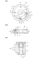
図1は、実施の形態1に係るVVT1の構成例を示す図であり、図1AはVVT1の正面図、図1Bは背面図、図1CはA-A断面図、図1Dは締結構造の拡大図である。なお、図1Aでは、第2のカバー5の一部を省略し、ケース2の内部構造を露出させてある。
図2は、従来のVVT1aの一例を示す図であり、図2Aは正面図、図2BはB-B断面図、図2Cは締結構造の拡大図である。図2において図1と同一又は相当する部分は、同一の符号を付し説明を省略する。図2Aでは、第2のカバー5の一部を省略し、ケース2の内部構造を露出させてある。
図4は、実施の形態2に係るVVT1の構成例を示す図であり、図4Aは正面図、図4BはD-D断面図、図4Cは締結構造の拡大図である。図4において図1と同一又は相当する部分は、同一の符号を付し説明を省略する。図4Aでは、第2のカバー5の一部を省略し、ケース2の内部構造を露出させてある。
実施の形態2に係るVVT1において、ナット7aの筒部7bはケース2に収納されるため、作業者が、ボルト6をナット7aに締結する際に工具等を用いてナット7aの回転を止めることは難しい。ボルト6締結時にナット7aが回転しないためには、ナット7aのフランジ部7dと第2のカバー5の凹部5bとの摩擦力がボルト6の締め付けトルクよりも大きくなる必要がある。そのためには、フランジ部7d又は凹部5bに、摩擦係数を増加させるための表面処理(例えば、ショットブラスト)が施されている必要がある。この表面処理はVVT1のコスト上昇を招く。そこで、実施の形態3では、上記の表面処理に代わる、より安価な回転止め機構をVVT1に追加する。
また、VVT1のコスト上昇が許容される場合、第1の回転止め部7eと第1の嵌合部5e、及び、第2の回転止め部7jと第2の嵌合部2jではなく、上記の表面処理が施されていてもよい。
図8は、実施の形態4に係るVVT1における締結構造の拡大図である。図8において図4と同一又は相当する部分は、同一の符号を付し説明を省略する。
Claims (3)
- クランクシャフトと同期回転する、筒状のケースと、
前記ケースに収納され、カムシャフトと同期回転するロータと、
第1の貫通穴を有し、前記ケースの一方の開口部を塞ぐ第1のカバーと、
第2の貫通穴を有し、前記ケースのもう一方の開口部を塞ぐ第2のカバーと、
前記第1の貫通穴を貫通し、前記第1のカバーから突出しない状態で前記第1のカバーと前記ケースとを固定する第1の締結部材と、
前記第2の貫通穴を貫通し、前記第2のカバーから突出しない状態で前記第2のカバーと前記ケースとを固定する第2の締結部材とを備え、
前記第2の締結部材は、内周面にメネジが設けられた、前記第2の貫通穴を貫通する筒部と、前記筒部の一端側に設けられて前記第2の貫通穴の縁部に引っ掛かるフランジ部とを有するナットであり、
前記第1の締結部材は、前記ナットに締結されるボルトであり、
前記ケースは、前記第1の貫通穴および前記第2の貫通穴に対向する位置に設けられた第3の貫通穴を有し、
前記第3の貫通穴は、前記ナットの前記筒部を収納する第1の部分と、前記ボルトを貫通させる第2の部分と、を有した貫通穴であり、
前記第1の部分の内径は、前記第2の部分の内径よりも大きく、
前記筒部は、前記フランジ部が設けられた一端側とは反対側に、前記第3の貫通穴における前記第2の部分の内径よりも大きい内径である、前記ボルトを貫通させる大内径部を有する
ことを特徴とするバルブタイミング調整装置。 - 前記フランジ部は、前記ナットの回転を防止する形状の第1の回転止め部を有し、
前記第2のカバーは、前記フランジ部の前記第1の回転止め部に嵌合する第1の嵌合部を有する
ことを特徴とする請求項1記載のバルブタイミング調整装置。 - 前記筒部は、外周面に設けられた、前記ナットの回転を防止する形状の第2の回転止め部を有し、
前記ケースは、前記第3の貫通穴の内周面に設けられた、前記筒部の前記第2の回転止め部に嵌合する第2の嵌合部を有する
ことを特徴とする請求項1記載のバルブタイミング調整装置。
Applications Claiming Priority (1)
| Application Number | Priority Date | Filing Date | Title |
|---|---|---|---|
| PCT/JP2019/041249 WO2021079396A1 (ja) | 2019-10-21 | 2019-10-21 | バルブタイミング調整装置 |
Publications (2)
| Publication Number | Publication Date |
|---|---|
| JPWO2021079396A1 JPWO2021079396A1 (ja) | 2021-04-29 |
| JP7345558B2 true JP7345558B2 (ja) | 2023-09-15 |
Family
ID=75620586
Family Applications (1)
| Application Number | Title | Priority Date | Filing Date |
|---|---|---|---|
| JP2021553175A Active JP7345558B2 (ja) | 2019-10-21 | 2019-10-21 | バルブタイミング調整装置 |
Country Status (4)
| Country | Link |
|---|---|
| US (1) | US20220316366A1 (ja) |
| JP (1) | JP7345558B2 (ja) |
| CN (1) | CN217002003U (ja) |
| WO (1) | WO2021079396A1 (ja) |
Citations (7)
| Publication number | Priority date | Publication date | Assignee | Title |
|---|---|---|---|---|
| JP2002061609A (ja) | 2000-08-21 | 2002-02-28 | Ckd Corp | シリンダの結合構造及びシリンダの結合方法 |
| JP2006138237A (ja) | 2004-11-11 | 2006-06-01 | Nittan Valve Co Ltd | 自動車用エンジンにおける位相可変装置 |
| JP2006328986A (ja) | 2005-05-24 | 2006-12-07 | Hitachi Ltd | 内燃機関のバルブタイミング制御装置 |
| JP2007064484A (ja) | 2005-08-31 | 2007-03-15 | Ejot Gmbh & Co Kg | ファスナのための雌部品 |
| JP2009215881A (ja) | 2006-07-05 | 2009-09-24 | Mitsubishi Electric Corp | バルブタイミング調整装置 |
| WO2015076324A1 (ja) | 2013-11-22 | 2015-05-28 | 矢崎総業株式会社 | 締結部材付き部品とその取付方法 |
| JP2016133163A (ja) | 2015-01-19 | 2016-07-25 | 三菱電機株式会社 | 繊維強化プラスチック部材の締結構造およびレーザ加工機 |
Family Cites Families (8)
| Publication number | Priority date | Publication date | Assignee | Title |
|---|---|---|---|---|
| JPS6173911U (ja) * | 1984-10-22 | 1986-05-19 | ||
| US4828441A (en) * | 1987-07-08 | 1989-05-09 | United Technologies Corporation | Locked threaded insert for high stress application |
| FR2690490A1 (fr) * | 1992-04-27 | 1993-10-29 | Peugeot | Assemblage d'une pièce contre une paroi d'un corps creux. |
| JP3191846B2 (ja) * | 1994-10-20 | 2001-07-23 | 株式会社デンソー | 内燃機関用バルブタイミング調整装置 |
| DE19958541A1 (de) * | 1999-12-04 | 2001-06-07 | Schaeffler Waelzlager Ohg | Vorrichtung zur Drehwinkelverstellung einer Nockenwelle |
| DE10054797A1 (de) * | 2000-11-04 | 2002-05-08 | Ina Schaeffler Kg | Verfahren und Vorrichtung zur Drehwinkelverstellung einer Welle gegenüber ihrem Antrieb |
| DE102010009394A1 (de) * | 2010-02-26 | 2011-09-01 | Schaeffler Technologies Gmbh & Co. Kg | Vorrichtung zur varibalen Einstellung der Steuerzeiten von Gaswechselventilen einer Brennkraftmaschine |
| DE102014201608A1 (de) * | 2014-01-30 | 2015-07-30 | Schaeffler Technologies AG & Co. KG | Nockenwellenversteller |
-
2019
- 2019-10-21 CN CN201990001466.XU patent/CN217002003U/zh active Active
- 2019-10-21 WO PCT/JP2019/041249 patent/WO2021079396A1/ja active Application Filing
- 2019-10-21 JP JP2021553175A patent/JP7345558B2/ja active Active
- 2019-10-21 US US17/634,171 patent/US20220316366A1/en not_active Abandoned
Patent Citations (7)
| Publication number | Priority date | Publication date | Assignee | Title |
|---|---|---|---|---|
| JP2002061609A (ja) | 2000-08-21 | 2002-02-28 | Ckd Corp | シリンダの結合構造及びシリンダの結合方法 |
| JP2006138237A (ja) | 2004-11-11 | 2006-06-01 | Nittan Valve Co Ltd | 自動車用エンジンにおける位相可変装置 |
| JP2006328986A (ja) | 2005-05-24 | 2006-12-07 | Hitachi Ltd | 内燃機関のバルブタイミング制御装置 |
| JP2007064484A (ja) | 2005-08-31 | 2007-03-15 | Ejot Gmbh & Co Kg | ファスナのための雌部品 |
| JP2009215881A (ja) | 2006-07-05 | 2009-09-24 | Mitsubishi Electric Corp | バルブタイミング調整装置 |
| WO2015076324A1 (ja) | 2013-11-22 | 2015-05-28 | 矢崎総業株式会社 | 締結部材付き部品とその取付方法 |
| JP2016133163A (ja) | 2015-01-19 | 2016-07-25 | 三菱電機株式会社 | 繊維強化プラスチック部材の締結構造およびレーザ加工機 |
Also Published As
| Publication number | Publication date |
|---|---|
| WO2021079396A1 (ja) | 2021-04-29 |
| CN217002003U (zh) | 2022-07-19 |
| US20220316366A1 (en) | 2022-10-06 |
| JPWO2021079396A1 (ja) | 2021-04-29 |
Similar Documents
| Publication | Publication Date | Title |
|---|---|---|
| US9422836B2 (en) | Valve timing control apparatus | |
| JP4161277B2 (ja) | 弁開閉時期制御装置 | |
| US7222598B2 (en) | Valve timing controller | |
| JP6443382B2 (ja) | バルブタイミング調整装置 | |
| JP7353789B2 (ja) | 波動歯車ユニット、歯車変速装置及びバルブタイミング変更装置 | |
| JP5184403B2 (ja) | 内燃機関のバルブタイミング制御装置 | |
| JP2006299891A (ja) | 駆動力伝達装置およびそれを用いた内燃機関用バルブタイミング調整装置 | |
| JP7345558B2 (ja) | バルブタイミング調整装置 | |
| KR101502877B1 (ko) | 밸브 개폐 시기 제어 장치 및 그 전방 부재의 고정 방법 | |
| JP2007127057A (ja) | バルブタイミング調整装置の取付構造 | |
| JP5900533B2 (ja) | バルブタイミング調整装置 | |
| JP7161917B2 (ja) | 位相変更ユニット及びバルブタイミング変更装置 | |
| US20200263572A1 (en) | Valve timing change device | |
| JP5179406B2 (ja) | 内燃機関のバルブタイミング制御装置 | |
| JP6436848B2 (ja) | バルブタイミング調整装置 | |
| JP7003024B2 (ja) | バルブタイミング調整装置 | |
| JP7131445B2 (ja) | バルブタイミング調整装置 | |
| JP6552777B2 (ja) | バルブタイミング調整装置 | |
| JP5447436B2 (ja) | バルブタイミング調整装置 | |
| JP6443294B2 (ja) | バルブタイミング調整装置 | |
| JP2006077662A (ja) | バルブタイミング調整装置 | |
| JP2007198258A (ja) | 位相可変装置および内燃機関用カム軸位相可変装置 | |
| JPH08312367A (ja) | 内燃機関用クランクスプロケット | |
| WO2020189482A1 (ja) | バルブタイミング調整装置 | |
| JP5562104B2 (ja) | バルブタイミング変更装置 |
Legal Events
| Date | Code | Title | Description |
|---|---|---|---|
| A621 | Written request for application examination |
Free format text: JAPANESE INTERMEDIATE CODE: A621 Effective date: 20211001 |
|
| A131 | Notification of reasons for refusal |
Free format text: JAPANESE INTERMEDIATE CODE: A131 Effective date: 20221018 |
|
| A521 | Request for written amendment filed |
Free format text: JAPANESE INTERMEDIATE CODE: A523 Effective date: 20221205 |
|
| A02 | Decision of refusal |
Free format text: JAPANESE INTERMEDIATE CODE: A02 Effective date: 20230328 |
|
| A521 | Request for written amendment filed |
Free format text: JAPANESE INTERMEDIATE CODE: A523 Effective date: 20230530 |
|
| A911 | Transfer to examiner for re-examination before appeal (zenchi) |
Free format text: JAPANESE INTERMEDIATE CODE: A911 Effective date: 20230606 |
|
| A131 | Notification of reasons for refusal |
Free format text: JAPANESE INTERMEDIATE CODE: A131 Effective date: 20230801 |
|
| A521 | Request for written amendment filed |
Free format text: JAPANESE INTERMEDIATE CODE: A523 Effective date: 20230810 |
|
| TRDD | Decision of grant or rejection written | ||
| A01 | Written decision to grant a patent or to grant a registration (utility model) |
Free format text: JAPANESE INTERMEDIATE CODE: A01 Effective date: 20230829 |
|
| A61 | First payment of annual fees (during grant procedure) |
Free format text: JAPANESE INTERMEDIATE CODE: A61 Effective date: 20230905 |
|
| R150 | Certificate of patent or registration of utility model |
Ref document number: 7345558 Country of ref document: JP Free format text: JAPANESE INTERMEDIATE CODE: R150 |