JP7341779B2 - 塗装ブース用の空調装置 - Google Patents
塗装ブース用の空調装置 Download PDFInfo
- Publication number
- JP7341779B2 JP7341779B2 JP2019143733A JP2019143733A JP7341779B2 JP 7341779 B2 JP7341779 B2 JP 7341779B2 JP 2019143733 A JP2019143733 A JP 2019143733A JP 2019143733 A JP2019143733 A JP 2019143733A JP 7341779 B2 JP7341779 B2 JP 7341779B2
- Authority
- JP
- Japan
- Prior art keywords
- air
- air conditioner
- humidifying
- mist
- intake port
- Prior art date
- Legal status (The legal status is an assumption and is not a legal conclusion. Google has not performed a legal analysis and makes no representation as to the accuracy of the status listed.)
- Active
Links
Images


Classifications
-
- F—MECHANICAL ENGINEERING; LIGHTING; HEATING; WEAPONS; BLASTING
- F24—HEATING; RANGES; VENTILATING
- F24F—AIR-CONDITIONING; AIR-HUMIDIFICATION; VENTILATION; USE OF AIR CURRENTS FOR SCREENING
- F24F6/00—Air-humidification, e.g. cooling by humidification
- F24F6/12—Air-humidification, e.g. cooling by humidification by forming water dispersions in the air
- F24F6/14—Air-humidification, e.g. cooling by humidification by forming water dispersions in the air using nozzles
-
- B—PERFORMING OPERATIONS; TRANSPORTING
- B05—SPRAYING OR ATOMISING IN GENERAL; APPLYING FLUENT MATERIALS TO SURFACES, IN GENERAL
- B05B—SPRAYING APPARATUS; ATOMISING APPARATUS; NOZZLES
- B05B16/00—Spray booths
- B05B16/40—Construction elements specially adapted therefor, e.g. floors, walls or ceilings
-
- F—MECHANICAL ENGINEERING; LIGHTING; HEATING; WEAPONS; BLASTING
- F24—HEATING; RANGES; VENTILATING
- F24F—AIR-CONDITIONING; AIR-HUMIDIFICATION; VENTILATION; USE OF AIR CURRENTS FOR SCREENING
- F24F3/00—Air-conditioning systems in which conditioned primary air is supplied from one or more central stations to distributing units in the rooms or spaces where it may receive secondary treatment; Apparatus specially designed for such systems
- F24F3/044—Systems in which all treatment is given in the central station, i.e. all-air systems
-
- B—PERFORMING OPERATIONS; TRANSPORTING
- B05—SPRAYING OR ATOMISING IN GENERAL; APPLYING FLUENT MATERIALS TO SURFACES, IN GENERAL
- B05B—SPRAYING APPARATUS; ATOMISING APPARATUS; NOZZLES
- B05B16/00—Spray booths
- B05B16/60—Ventilation arrangements specially adapted therefor
-
- B—PERFORMING OPERATIONS; TRANSPORTING
- B05—SPRAYING OR ATOMISING IN GENERAL; APPLYING FLUENT MATERIALS TO SURFACES, IN GENERAL
- B05B—SPRAYING APPARATUS; ATOMISING APPARATUS; NOZZLES
- B05B14/00—Arrangements for collecting, re-using or eliminating excess spraying material
- B05B14/40—Arrangements for collecting, re-using or eliminating excess spraying material for use in spray booths
- B05B14/43—Arrangements for collecting, re-using or eliminating excess spraying material for use in spray booths by filtering the air charged with excess material
-
- B—PERFORMING OPERATIONS; TRANSPORTING
- B05—SPRAYING OR ATOMISING IN GENERAL; APPLYING FLUENT MATERIALS TO SURFACES, IN GENERAL
- B05B—SPRAYING APPARATUS; ATOMISING APPARATUS; NOZZLES
- B05B7/00—Spraying apparatus for discharge of liquids or other fluent materials from two or more sources, e.g. of liquid and air, of powder and gas
- B05B7/0075—Nozzle arrangements in gas streams
-
- F—MECHANICAL ENGINEERING; LIGHTING; HEATING; WEAPONS; BLASTING
- F24—HEATING; RANGES; VENTILATING
- F24F—AIR-CONDITIONING; AIR-HUMIDIFICATION; VENTILATION; USE OF AIR CURRENTS FOR SCREENING
- F24F3/00—Air-conditioning systems in which conditioned primary air is supplied from one or more central stations to distributing units in the rooms or spaces where it may receive secondary treatment; Apparatus specially designed for such systems
- F24F3/12—Air-conditioning systems in which conditioned primary air is supplied from one or more central stations to distributing units in the rooms or spaces where it may receive secondary treatment; Apparatus specially designed for such systems characterised by the treatment of the air otherwise than by heating and cooling
- F24F3/14—Air-conditioning systems in which conditioned primary air is supplied from one or more central stations to distributing units in the rooms or spaces where it may receive secondary treatment; Apparatus specially designed for such systems characterised by the treatment of the air otherwise than by heating and cooling by humidification; by dehumidification
- F24F3/147—Air-conditioning systems in which conditioned primary air is supplied from one or more central stations to distributing units in the rooms or spaces where it may receive secondary treatment; Apparatus specially designed for such systems characterised by the treatment of the air otherwise than by heating and cooling by humidification; by dehumidification with both heat and humidity transfer between supplied and exhausted air
-
- F—MECHANICAL ENGINEERING; LIGHTING; HEATING; WEAPONS; BLASTING
- F24—HEATING; RANGES; VENTILATING
- F24F—AIR-CONDITIONING; AIR-HUMIDIFICATION; VENTILATION; USE OF AIR CURRENTS FOR SCREENING
- F24F3/00—Air-conditioning systems in which conditioned primary air is supplied from one or more central stations to distributing units in the rooms or spaces where it may receive secondary treatment; Apparatus specially designed for such systems
- F24F3/12—Air-conditioning systems in which conditioned primary air is supplied from one or more central stations to distributing units in the rooms or spaces where it may receive secondary treatment; Apparatus specially designed for such systems characterised by the treatment of the air otherwise than by heating and cooling
- F24F3/14—Air-conditioning systems in which conditioned primary air is supplied from one or more central stations to distributing units in the rooms or spaces where it may receive secondary treatment; Apparatus specially designed for such systems characterised by the treatment of the air otherwise than by heating and cooling by humidification; by dehumidification
- F24F3/153—Air-conditioning systems in which conditioned primary air is supplied from one or more central stations to distributing units in the rooms or spaces where it may receive secondary treatment; Apparatus specially designed for such systems characterised by the treatment of the air otherwise than by heating and cooling by humidification; by dehumidification with subsequent heating, i.e. with the air, given the required humidity in the central station, passing a heating element to achieve the required temperature
-
- F—MECHANICAL ENGINEERING; LIGHTING; HEATING; WEAPONS; BLASTING
- F24—HEATING; RANGES; VENTILATING
- F24F—AIR-CONDITIONING; AIR-HUMIDIFICATION; VENTILATION; USE OF AIR CURRENTS FOR SCREENING
- F24F6/00—Air-humidification, e.g. cooling by humidification
- F24F6/02—Air-humidification, e.g. cooling by humidification by evaporation of water in the air
- F24F6/04—Air-humidification, e.g. cooling by humidification by evaporation of water in the air using stationary unheated wet elements
-
- B—PERFORMING OPERATIONS; TRANSPORTING
- B05—SPRAYING OR ATOMISING IN GENERAL; APPLYING FLUENT MATERIALS TO SURFACES, IN GENERAL
- B05B—SPRAYING APPARATUS; ATOMISING APPARATUS; NOZZLES
- B05B1/00—Nozzles, spray heads or other outlets, with or without auxiliary devices such as valves, heating means
- B05B1/14—Nozzles, spray heads or other outlets, with or without auxiliary devices such as valves, heating means with multiple outlet openings; with strainers in or outside the outlet opening
- B05B1/20—Arrangements of several outlets along elongated bodies, e.g. perforated pipes or troughs, e.g. spray booms; Outlet elements therefor
- B05B1/205—Arrangements of several outlets along elongated bodies, e.g. perforated pipes or troughs, e.g. spray booms; Outlet elements therefor characterised by the longitudinal shape of the elongated body
-
- B—PERFORMING OPERATIONS; TRANSPORTING
- B05—SPRAYING OR ATOMISING IN GENERAL; APPLYING FLUENT MATERIALS TO SURFACES, IN GENERAL
- B05B—SPRAYING APPARATUS; ATOMISING APPARATUS; NOZZLES
- B05B13/00—Machines or plants for applying liquids or other fluent materials to surfaces of objects or other work by spraying, not covered by groups B05B1/00 - B05B11/00
- B05B13/02—Means for supporting work; Arrangement or mounting of spray heads; Adaptation or arrangement of means for feeding work
- B05B13/04—Means for supporting work; Arrangement or mounting of spray heads; Adaptation or arrangement of means for feeding work the spray heads being moved during spraying operation
- B05B13/0431—Means for supporting work; Arrangement or mounting of spray heads; Adaptation or arrangement of means for feeding work the spray heads being moved during spraying operation with spray heads moved by robots or articulated arms, e.g. for applying liquid or other fluent material to 3D-surfaces
-
- B—PERFORMING OPERATIONS; TRANSPORTING
- B05—SPRAYING OR ATOMISING IN GENERAL; APPLYING FLUENT MATERIALS TO SURFACES, IN GENERAL
- B05B—SPRAYING APPARATUS; ATOMISING APPARATUS; NOZZLES
- B05B17/00—Apparatus for spraying or atomising liquids or other fluent materials, not covered by the preceding groups
- B05B17/04—Apparatus for spraying or atomising liquids or other fluent materials, not covered by the preceding groups operating with special methods
- B05B17/06—Apparatus for spraying or atomising liquids or other fluent materials, not covered by the preceding groups operating with special methods using ultrasonic or other kinds of vibrations
-
- B—PERFORMING OPERATIONS; TRANSPORTING
- B05—SPRAYING OR ATOMISING IN GENERAL; APPLYING FLUENT MATERIALS TO SURFACES, IN GENERAL
- B05B—SPRAYING APPARATUS; ATOMISING APPARATUS; NOZZLES
- B05B9/00—Spraying apparatus for discharge of liquids or other fluent material, without essentially mixing with gas or vapour
- B05B9/03—Spraying apparatus for discharge of liquids or other fluent material, without essentially mixing with gas or vapour characterised by means for supplying liquid or other fluent material
- B05B9/04—Spraying apparatus for discharge of liquids or other fluent material, without essentially mixing with gas or vapour characterised by means for supplying liquid or other fluent material with pressurised or compressible container; with pump
- B05B9/0403—Spraying apparatus for discharge of liquids or other fluent material, without essentially mixing with gas or vapour characterised by means for supplying liquid or other fluent material with pressurised or compressible container; with pump with pumps for liquids or other fluent material
- B05B9/0423—Spraying apparatus for discharge of liquids or other fluent material, without essentially mixing with gas or vapour characterised by means for supplying liquid or other fluent material with pressurised or compressible container; with pump with pumps for liquids or other fluent material for supplying liquid or other fluent material to several spraying apparatus
-
- F—MECHANICAL ENGINEERING; LIGHTING; HEATING; WEAPONS; BLASTING
- F24—HEATING; RANGES; VENTILATING
- F24F—AIR-CONDITIONING; AIR-HUMIDIFICATION; VENTILATION; USE OF AIR CURRENTS FOR SCREENING
- F24F6/00—Air-humidification, e.g. cooling by humidification
- F24F6/12—Air-humidification, e.g. cooling by humidification by forming water dispersions in the air
- F24F6/14—Air-humidification, e.g. cooling by humidification by forming water dispersions in the air using nozzles
- F24F2006/146—Air-humidification, e.g. cooling by humidification by forming water dispersions in the air using nozzles using pressurised water for spraying
-
- Y—GENERAL TAGGING OF NEW TECHNOLOGICAL DEVELOPMENTS; GENERAL TAGGING OF CROSS-SECTIONAL TECHNOLOGIES SPANNING OVER SEVERAL SECTIONS OF THE IPC; TECHNICAL SUBJECTS COVERED BY FORMER USPC CROSS-REFERENCE ART COLLECTIONS [XRACs] AND DIGESTS
- Y02—TECHNOLOGIES OR APPLICATIONS FOR MITIGATION OR ADAPTATION AGAINST CLIMATE CHANGE
- Y02B—CLIMATE CHANGE MITIGATION TECHNOLOGIES RELATED TO BUILDINGS, e.g. HOUSING, HOUSE APPLIANCES OR RELATED END-USER APPLICATIONS
- Y02B30/00—Energy efficient heating, ventilation or air conditioning [HVAC]
- Y02B30/54—Free-cooling systems
Description
11 :取込口
12 :吐出口
13 :筐体
20 :加温手段
30 :加湿手段
31 :ミストノズル
40 :気化手段
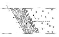
41 :エレメント
41a :上縁
41b :下縁
50 :温湿度調節手段
60 :塗装ブース
62 :被塗物
Claims (5)
- 被塗物に塗装を行う塗装ブースに空気を供給する供給口が設けられた筐体と、
前記筐体に空気を取り込む取込口と、
前記取込口から取り込まれた空気に対して加湿ミストを噴霧する加湿手段と、
前記加湿手段と前記供給口との間に配され、加湿ミストの粒子径よりも小さい空孔が設けられた多孔質体からなる複数枚の板状のエレメントと、を備え、
前記複数枚の板状のエレメントは、上下方向に互いに離間して前記取込口から前記供給口へ向かって上向きとなるように傾斜して配置され、かつ、上下に隣り合うエレメントどうしにおいて、上側の前記エレメントの下縁が、下側の前記エレメントの上縁よりも下方に位置するように配置され、
前記加湿ミストが噴霧された空気は、前記複数枚の板状のエレメントを通過することによって未気化の加湿ミストが空気と接触して気化することを特徴とする空調装置。 - 各前記エレメントは、水平に対して45~85度の範囲の傾斜姿勢で配置されている請求項1に記載の空調装置。
- 前記エレメントは、セラミックボード又は金属焼結体の多孔質体を有する請求項1または2に記載の空調装置。
- 前記取込口と前記加湿手段との間に配され、前記取込口から取り込まれた空気を加温する加温手段を備える請求項1から3のいずれか一項に記載の空調装置。
- 前記複数枚の板状のエレメントと前記供給口との間に配され、前記複数枚の板状のエレメントを通過した空気を温湿度調節する温湿度調節手段を備える請求項1から4のいずれか一項に記載の空調装置。
Priority Applications (5)
| Application Number | Priority Date | Filing Date | Title |
|---|---|---|---|
| JP2019143733A JP7341779B2 (ja) | 2019-08-05 | 2019-08-05 | 塗装ブース用の空調装置 |
| KR1020217020592A KR102619498B1 (ko) | 2019-08-05 | 2020-07-28 | 도장 부스용의 공조 장치 |
| PCT/JP2020/028873 WO2021024857A1 (ja) | 2019-08-05 | 2020-07-28 | 塗装ブース用の空調装置 |
| CN202080004579.2A CN112654434B (zh) | 2019-08-05 | 2020-07-28 | 涂装室用的空调装置 |
| US17/272,480 US20210325059A1 (en) | 2019-08-05 | 2020-07-28 | Air Conditioner for Paint Booth |
Applications Claiming Priority (1)
| Application Number | Priority Date | Filing Date | Title |
|---|---|---|---|
| JP2019143733A JP7341779B2 (ja) | 2019-08-05 | 2019-08-05 | 塗装ブース用の空調装置 |
Publications (3)
| Publication Number | Publication Date |
|---|---|
| JP2021025697A JP2021025697A (ja) | 2021-02-22 |
| JP2021025697A5 JP2021025697A5 (ja) | 2022-01-28 |
| JP7341779B2 true JP7341779B2 (ja) | 2023-09-11 |
Family
ID=74503616
Family Applications (1)
| Application Number | Title | Priority Date | Filing Date |
|---|---|---|---|
| JP2019143733A Active JP7341779B2 (ja) | 2019-08-05 | 2019-08-05 | 塗装ブース用の空調装置 |
Country Status (5)
| Country | Link |
|---|---|
| US (1) | US20210325059A1 (ja) |
| JP (1) | JP7341779B2 (ja) |
| KR (1) | KR102619498B1 (ja) |
| CN (1) | CN112654434B (ja) |
| WO (1) | WO2021024857A1 (ja) |
Citations (1)
| Publication number | Priority date | Publication date | Assignee | Title |
|---|---|---|---|---|
| JP2012122671A (ja) | 2010-12-08 | 2012-06-28 | Sanki Eng Co Ltd | 水噴霧加湿装置 |
Family Cites Families (28)
| Publication number | Priority date | Publication date | Assignee | Title |
|---|---|---|---|---|
| JPS5922586B2 (ja) * | 1979-02-27 | 1984-05-28 | 日産自動車株式会社 | 塗装用空気調和装置 |
| JPS6125537Y2 (ja) * | 1980-03-14 | 1986-08-01 | ||
| JPS57165063A (en) * | 1981-04-07 | 1982-10-09 | Nissan Motor Co Ltd | Air-conditioner for coating |
| JPS6354535A (ja) * | 1986-08-22 | 1988-03-08 | Chizuko Ozawa | 冷房装置 |
| JP2543648Y2 (ja) * | 1993-12-10 | 1997-08-13 | 株式会社ワコー | スプレー式加湿機 |
| JP3120021B2 (ja) * | 1995-06-19 | 2000-12-25 | クボタ空調株式会社 | 蒸気加湿器 |
| US6059866A (en) * | 1997-09-30 | 2000-05-09 | Sanki Engineering Co., Ltd | Air washer |
| JP2004053238A (ja) * | 2002-07-23 | 2004-02-19 | Shinei Sangyo Kk | 調湿機 |
| CN200952794Y (zh) * | 2006-04-10 | 2007-09-26 | 爱克斯爱尔(北京)加湿系统有限公司 | 中央空调加湿系统 |
| JP4816251B2 (ja) * | 2006-05-26 | 2011-11-16 | マックス株式会社 | 空調装置及び建物 |
| US7291196B1 (en) * | 2006-11-16 | 2007-11-06 | Lerner Bernard J | Filamentary pad for improved mist elimination and mass transfer |
| KR20080056595A (ko) * | 2006-12-18 | 2008-06-23 | 강경형 | 증기발생 장치 |
| CN101617175A (zh) * | 2007-03-28 | 2009-12-30 | 东芝开利株式会社 | 加湿装置和空调机 |
| JP5493814B2 (ja) | 2009-12-16 | 2014-05-14 | マツダ株式会社 | 塗装用空調装置の制御方法及びその装置 |
| US8273158B2 (en) * | 2010-11-29 | 2012-09-25 | General Electric Company | Mist eliminator, moisture removal system, and method of removing water particles from inlet air |
| JP2013213616A (ja) * | 2012-04-02 | 2013-10-17 | Fuji Electric Co Ltd | 気化冷却装置、およびその制御方法 |
| JP5839483B2 (ja) * | 2012-05-29 | 2016-01-06 | トリニティ工業株式会社 | 塗装ブース用空調装置 |
| JP6167326B2 (ja) * | 2013-03-14 | 2017-07-26 | パナソニックIpマネジメント株式会社 | 塗装ミスト処理装置 |
| JP6169432B2 (ja) * | 2013-07-26 | 2017-07-26 | 大阪瓦斯株式会社 | 加湿器 |
| KR101552874B1 (ko) * | 2015-05-28 | 2015-09-14 | 김정우 | 초입자 분무장치 |
| US9982907B2 (en) * | 2015-07-17 | 2018-05-29 | Valeriy S. Maisotsenko | Method and systems for energy-saving heating and humidifying of buildings using outside air |
| DE102016114466A1 (de) * | 2016-08-04 | 2018-02-08 | Eisenmann Se | Konditioniervorrichtung und Verfahren zum Konditionieren eines gasförmigen Mediums sowie Anlage und Verfahren zum Behandeln von Werkstücken |
| DE102016124478A1 (de) | 2016-12-15 | 2018-06-21 | Eisenmann Se | Vorrichtung zum Befeuchten eines Luftstroms |
| JP2018162909A (ja) | 2017-03-24 | 2018-10-18 | トヨタ自動車株式会社 | 気化式加湿器 |
| KR101938689B1 (ko) * | 2017-04-21 | 2019-04-10 | 한정흠 | 미세먼지포집 및 가습기능을 갖는 에너지 절약형 공기조화기 |
| JP6970962B2 (ja) * | 2017-09-22 | 2021-11-24 | 株式会社Japan Zero | 塗装システム |
| JP2019072695A (ja) * | 2017-10-18 | 2019-05-16 | 株式会社エー・イー・エス | クローズド塗装装置 |
| CN208170612U (zh) * | 2018-03-26 | 2018-11-30 | 维谛技术有限公司 | 一种加湿装置 |
-
2019
- 2019-08-05 JP JP2019143733A patent/JP7341779B2/ja active Active
-
2020
- 2020-07-28 US US17/272,480 patent/US20210325059A1/en active Pending
- 2020-07-28 CN CN202080004579.2A patent/CN112654434B/zh active Active
- 2020-07-28 KR KR1020217020592A patent/KR102619498B1/ko active IP Right Grant
- 2020-07-28 WO PCT/JP2020/028873 patent/WO2021024857A1/ja active Application Filing
Patent Citations (1)
| Publication number | Priority date | Publication date | Assignee | Title |
|---|---|---|---|---|
| JP2012122671A (ja) | 2010-12-08 | 2012-06-28 | Sanki Eng Co Ltd | 水噴霧加湿装置 |
Also Published As
| Publication number | Publication date |
|---|---|
| US20210325059A1 (en) | 2021-10-21 |
| CN112654434B (zh) | 2023-02-24 |
| WO2021024857A1 (ja) | 2021-02-11 |
| KR102619498B1 (ko) | 2023-12-28 |
| CN112654434A (zh) | 2021-04-13 |
| JP2021025697A (ja) | 2021-02-22 |
| KR20210099083A (ko) | 2021-08-11 |
Similar Documents
| Publication | Publication Date | Title |
|---|---|---|
| US11639801B2 (en) | Methods, systems, and devices for humidifying | |
| US6129285A (en) | System and method for air humidification | |
| US7752860B2 (en) | Method and apparatus for improving evaporator performance | |
| US20040003619A1 (en) | Surface treatment method for improving the surface wettability of wet surface heat exchangers | |
| KR20110016861A (ko) | 온습도 조정 장치 및 온습도 조정 방법 | |
| US20210123695A1 (en) | Heat exchanger with spray nozzle | |
| KR100924960B1 (ko) | 크린룸내 직접분무식 기화가습장치 및 습도제어방법 | |
| JP7341779B2 (ja) | 塗装ブース用の空調装置 | |
| KR100874886B1 (ko) | 크린룸내 직접분무식 기화가습장치 및 습도제어방법 | |
| JP2014202438A (ja) | 加湿器 | |
| WO2011078757A1 (en) | A method and an apparatus in a ventilation system | |
| JP6831160B2 (ja) | 水噴霧型加湿装置 | |
| CN209522894U (zh) | 一种带钢镀后空气加湿冷却系统 | |
| JP2021025697A5 (ja) | ||
| KR20120013789A (ko) | 미세 물 분무수단을 구비한 공조기 | |
| CN109457205A (zh) | 一种带钢镀后空气加湿冷却方法及冷却系统 | |
| TH2101000850A (th) | เครื่องปรับอากาศสำหรับห้องพ่นสี | |
| CN215951648U (zh) | 加湿装置和空调系统 | |
| JP2001330285A (ja) | 調湿用ノズル | |
| US11226123B2 (en) | Inductive-humidification and evaporative-cooling ventilation system | |
| JP2019007664A (ja) | 水膜気化式加湿器 | |
| FI124958B (fi) | Ilmastointijärjestelmä tilan kostuttamiseksi ja vastaava ilmastoinnin päätelaite | |
| TWM638397U (zh) | 具高精密水溫控制之濕度控制裝置 | |
| JPS6229841A (ja) | 空気調和機 | |
| IT201900003345A1 (it) | Apparato e metodo di raffreddamento per uno scambiatore di calore e scambiatore di calore |
Legal Events
| Date | Code | Title | Description |
|---|---|---|---|
| A521 | Request for written amendment filed |
Free format text: JAPANESE INTERMEDIATE CODE: A523 Effective date: 20220119 |
|
| A621 | Written request for application examination |
Free format text: JAPANESE INTERMEDIATE CODE: A621 Effective date: 20220119 |
|
| A131 | Notification of reasons for refusal |
Free format text: JAPANESE INTERMEDIATE CODE: A131 Effective date: 20230307 |
|
| A521 | Request for written amendment filed |
Free format text: JAPANESE INTERMEDIATE CODE: A523 Effective date: 20230426 |
|
| TRDD | Decision of grant or rejection written | ||
| A01 | Written decision to grant a patent or to grant a registration (utility model) |
Free format text: JAPANESE INTERMEDIATE CODE: A01 Effective date: 20230816 |
|
| A61 | First payment of annual fees (during grant procedure) |
Free format text: JAPANESE INTERMEDIATE CODE: A61 Effective date: 20230830 |
|
| R150 | Certificate of patent or registration of utility model |
Ref document number: 7341779 Country of ref document: JP Free format text: JAPANESE INTERMEDIATE CODE: R150 |