JP7120903B2 - LASER PROCESSING APPARATUS AND LASER PROCESSING METHOD - Google Patents

LASER PROCESSING APPARATUS AND LASER PROCESSING METHOD Download PDF

Info

Publication number
JP7120903B2
JP7120903B2 JP2018234809A JP2018234809A JP7120903B2 JP 7120903 B2 JP7120903 B2 JP 7120903B2 JP 2018234809 A JP2018234809 A JP 2018234809A JP 2018234809 A JP2018234809 A JP 2018234809A JP 7120903 B2 JP7120903 B2 JP 7120903B2
Authority
JP
Japan
Prior art keywords
region
laser
orientation
line
laser processing
Prior art date
Legal status (The legal status is an assumption and is not a legal conclusion. Google has not performed a legal analysis and makes no representation as to the accuracy of the status listed.)
Active
Application number
JP2018234809A
Other languages
Japanese (ja)
Other versions
JP2020069530A (en
Inventor
剛志 坂本
克洋 是松
Current Assignee (The listed assignees may be inaccurate. Google has not performed a legal analysis and makes no representation or warranty as to the accuracy of the list.)
Hamamatsu Photonics KK
Original Assignee
Hamamatsu Photonics KK
Priority date (The priority date is an assumption and is not a legal conclusion. Google has not performed a legal analysis and makes no representation as to the accuracy of the date listed.)
Filing date
Publication date
Application filed by Hamamatsu Photonics KK filed Critical Hamamatsu Photonics KK
Priority to KR1020217015678A priority Critical patent/KR20210080513A/en
Priority to DE112019005451.1T priority patent/DE112019005451T5/en
Priority to CN201980072868.3A priority patent/CN113165120B/en
Priority to US17/288,841 priority patent/US11897056B2/en
Priority to TW108139199A priority patent/TW202023724A/en
Priority to PCT/JP2019/042589 priority patent/WO2020090894A1/en
Publication of JP2020069530A publication Critical patent/JP2020069530A/en
Application granted granted Critical
Publication of JP7120903B2 publication Critical patent/JP7120903B2/en
Active legal-status Critical Current
Anticipated expiration legal-status Critical

Links

Images

Classifications

    • HELECTRICITY
    • H01ELECTRIC ELEMENTS
    • H01LSEMICONDUCTOR DEVICES NOT COVERED BY CLASS H10
    • H01L21/00Processes or apparatus adapted for the manufacture or treatment of semiconductor or solid state devices or of parts thereof
    • H01L21/70Manufacture or treatment of devices consisting of a plurality of solid state components formed in or on a common substrate or of parts thereof; Manufacture of integrated circuit devices or of parts thereof
    • H01L21/77Manufacture or treatment of devices consisting of a plurality of solid state components or integrated circuits formed in, or on, a common substrate
    • H01L21/78Manufacture or treatment of devices consisting of a plurality of solid state components or integrated circuits formed in, or on, a common substrate with subsequent division of the substrate into plural individual devices
    • H01L21/7806Manufacture or treatment of devices consisting of a plurality of solid state components or integrated circuits formed in, or on, a common substrate with subsequent division of the substrate into plural individual devices involving the separation of the active layers from a substrate
    • BPERFORMING OPERATIONS; TRANSPORTING
    • B23MACHINE TOOLS; METAL-WORKING NOT OTHERWISE PROVIDED FOR
    • B23KSOLDERING OR UNSOLDERING; WELDING; CLADDING OR PLATING BY SOLDERING OR WELDING; CUTTING BY APPLYING HEAT LOCALLY, e.g. FLAME CUTTING; WORKING BY LASER BEAM
    • B23K26/00Working by laser beam, e.g. welding, cutting or boring
    • B23K26/50Working by transmitting the laser beam through or within the workpiece
    • B23K26/53Working by transmitting the laser beam through or within the workpiece for modifying or reforming the material inside the workpiece, e.g. for producing break initiation cracks
    • BPERFORMING OPERATIONS; TRANSPORTING
    • B23MACHINE TOOLS; METAL-WORKING NOT OTHERWISE PROVIDED FOR
    • B23KSOLDERING OR UNSOLDERING; WELDING; CLADDING OR PLATING BY SOLDERING OR WELDING; CUTTING BY APPLYING HEAT LOCALLY, e.g. FLAME CUTTING; WORKING BY LASER BEAM
    • B23K26/00Working by laser beam, e.g. welding, cutting or boring
    • B23K26/08Devices involving relative movement between laser beam and workpiece
    • B23K26/0823Devices involving rotation of the workpiece
    • BPERFORMING OPERATIONS; TRANSPORTING
    • B23MACHINE TOOLS; METAL-WORKING NOT OTHERWISE PROVIDED FOR
    • B23KSOLDERING OR UNSOLDERING; WELDING; CLADDING OR PLATING BY SOLDERING OR WELDING; CUTTING BY APPLYING HEAT LOCALLY, e.g. FLAME CUTTING; WORKING BY LASER BEAM
    • B23K26/00Working by laser beam, e.g. welding, cutting or boring
    • B23K26/0006Working by laser beam, e.g. welding, cutting or boring taking account of the properties of the material involved
    • BPERFORMING OPERATIONS; TRANSPORTING
    • B23MACHINE TOOLS; METAL-WORKING NOT OTHERWISE PROVIDED FOR
    • B23KSOLDERING OR UNSOLDERING; WELDING; CLADDING OR PLATING BY SOLDERING OR WELDING; CUTTING BY APPLYING HEAT LOCALLY, e.g. FLAME CUTTING; WORKING BY LASER BEAM
    • B23K26/00Working by laser beam, e.g. welding, cutting or boring
    • B23K26/02Positioning or observing the workpiece, e.g. with respect to the point of impact; Aligning, aiming or focusing the laser beam
    • B23K26/06Shaping the laser beam, e.g. by masks or multi-focusing
    • B23K26/0604Shaping the laser beam, e.g. by masks or multi-focusing by a combination of beams
    • BPERFORMING OPERATIONS; TRANSPORTING
    • B23MACHINE TOOLS; METAL-WORKING NOT OTHERWISE PROVIDED FOR
    • B23KSOLDERING OR UNSOLDERING; WELDING; CLADDING OR PLATING BY SOLDERING OR WELDING; CUTTING BY APPLYING HEAT LOCALLY, e.g. FLAME CUTTING; WORKING BY LASER BEAM
    • B23K26/00Working by laser beam, e.g. welding, cutting or boring
    • B23K26/02Positioning or observing the workpiece, e.g. with respect to the point of impact; Aligning, aiming or focusing the laser beam
    • B23K26/06Shaping the laser beam, e.g. by masks or multi-focusing
    • B23K26/062Shaping the laser beam, e.g. by masks or multi-focusing by direct control of the laser beam
    • B23K26/0622Shaping the laser beam, e.g. by masks or multi-focusing by direct control of the laser beam by shaping pulses
    • BPERFORMING OPERATIONS; TRANSPORTING
    • B23MACHINE TOOLS; METAL-WORKING NOT OTHERWISE PROVIDED FOR
    • B23KSOLDERING OR UNSOLDERING; WELDING; CLADDING OR PLATING BY SOLDERING OR WELDING; CUTTING BY APPLYING HEAT LOCALLY, e.g. FLAME CUTTING; WORKING BY LASER BEAM
    • B23K26/00Working by laser beam, e.g. welding, cutting or boring
    • B23K26/02Positioning or observing the workpiece, e.g. with respect to the point of impact; Aligning, aiming or focusing the laser beam
    • B23K26/06Shaping the laser beam, e.g. by masks or multi-focusing
    • B23K26/064Shaping the laser beam, e.g. by masks or multi-focusing by means of optical elements, e.g. lenses, mirrors or prisms
    • BPERFORMING OPERATIONS; TRANSPORTING
    • B23MACHINE TOOLS; METAL-WORKING NOT OTHERWISE PROVIDED FOR
    • B23KSOLDERING OR UNSOLDERING; WELDING; CLADDING OR PLATING BY SOLDERING OR WELDING; CUTTING BY APPLYING HEAT LOCALLY, e.g. FLAME CUTTING; WORKING BY LASER BEAM
    • B23K26/00Working by laser beam, e.g. welding, cutting or boring
    • B23K26/08Devices involving relative movement between laser beam and workpiece
    • B23K26/083Devices involving movement of the workpiece in at least one axial direction
    • B23K26/0853Devices involving movement of the workpiece in at least in two axial directions, e.g. in a plane
    • BPERFORMING OPERATIONS; TRANSPORTING
    • B23MACHINE TOOLS; METAL-WORKING NOT OTHERWISE PROVIDED FOR
    • B23KSOLDERING OR UNSOLDERING; WELDING; CLADDING OR PLATING BY SOLDERING OR WELDING; CUTTING BY APPLYING HEAT LOCALLY, e.g. FLAME CUTTING; WORKING BY LASER BEAM
    • B23K26/00Working by laser beam, e.g. welding, cutting or boring
    • B23K26/08Devices involving relative movement between laser beam and workpiece
    • B23K26/0869Devices involving movement of the laser head in at least one axial direction
    • B23K26/0876Devices involving movement of the laser head in at least one axial direction in at least two axial directions
    • B23K26/0884Devices involving movement of the laser head in at least one axial direction in at least two axial directions in at least in three axial directions, e.g. manipulators, robots
    • BPERFORMING OPERATIONS; TRANSPORTING
    • B23MACHINE TOOLS; METAL-WORKING NOT OTHERWISE PROVIDED FOR
    • B23KSOLDERING OR UNSOLDERING; WELDING; CLADDING OR PLATING BY SOLDERING OR WELDING; CUTTING BY APPLYING HEAT LOCALLY, e.g. FLAME CUTTING; WORKING BY LASER BEAM
    • B23K26/00Working by laser beam, e.g. welding, cutting or boring
    • B23K26/351Working by laser beam, e.g. welding, cutting or boring for trimming or tuning of electrical components
    • BPERFORMING OPERATIONS; TRANSPORTING
    • B23MACHINE TOOLS; METAL-WORKING NOT OTHERWISE PROVIDED FOR
    • B23KSOLDERING OR UNSOLDERING; WELDING; CLADDING OR PLATING BY SOLDERING OR WELDING; CUTTING BY APPLYING HEAT LOCALLY, e.g. FLAME CUTTING; WORKING BY LASER BEAM
    • B23K37/00Auxiliary devices or processes, not specially adapted to a procedure covered by only one of the preceding main groups
    • B23K37/02Carriages for supporting the welding or cutting element
    • B23K37/0211Carriages for supporting the welding or cutting element travelling on a guide member, e.g. rail, track
    • B23K37/0235Carriages for supporting the welding or cutting element travelling on a guide member, e.g. rail, track the guide member forming part of a portal
    • HELECTRICITY
    • H01ELECTRIC ELEMENTS
    • H01LSEMICONDUCTOR DEVICES NOT COVERED BY CLASS H10
    • H01L21/00Processes or apparatus adapted for the manufacture or treatment of semiconductor or solid state devices or of parts thereof
    • H01L21/02Manufacture or treatment of semiconductor devices or of parts thereof
    • H01L21/04Manufacture or treatment of semiconductor devices or of parts thereof the devices having at least one potential-jump barrier or surface barrier, e.g. PN junction, depletion layer or carrier concentration layer
    • H01L21/18Manufacture or treatment of semiconductor devices or of parts thereof the devices having at least one potential-jump barrier or surface barrier, e.g. PN junction, depletion layer or carrier concentration layer the devices having semiconductor bodies comprising elements of Group IV of the Periodic System or AIIIBV compounds with or without impurities, e.g. doping materials
    • H01L21/30Treatment of semiconductor bodies using processes or apparatus not provided for in groups H01L21/20 - H01L21/26
    • H01L21/302Treatment of semiconductor bodies using processes or apparatus not provided for in groups H01L21/20 - H01L21/26 to change their surface-physical characteristics or shape, e.g. etching, polishing, cutting
    • H01L21/304Mechanical treatment, e.g. grinding, polishing, cutting
    • BPERFORMING OPERATIONS; TRANSPORTING
    • B23MACHINE TOOLS; METAL-WORKING NOT OTHERWISE PROVIDED FOR
    • B23KSOLDERING OR UNSOLDERING; WELDING; CLADDING OR PLATING BY SOLDERING OR WELDING; CUTTING BY APPLYING HEAT LOCALLY, e.g. FLAME CUTTING; WORKING BY LASER BEAM
    • B23K2101/00Articles made by soldering, welding or cutting
    • B23K2101/36Electric or electronic devices
    • B23K2101/40Semiconductor devices
    • BPERFORMING OPERATIONS; TRANSPORTING
    • B23MACHINE TOOLS; METAL-WORKING NOT OTHERWISE PROVIDED FOR
    • B23KSOLDERING OR UNSOLDERING; WELDING; CLADDING OR PLATING BY SOLDERING OR WELDING; CUTTING BY APPLYING HEAT LOCALLY, e.g. FLAME CUTTING; WORKING BY LASER BEAM
    • B23K2103/00Materials to be soldered, welded or cut
    • B23K2103/50Inorganic material, e.g. metals, not provided for in B23K2103/02 – B23K2103/26
    • B23K2103/56Inorganic material, e.g. metals, not provided for in B23K2103/02 – B23K2103/26 semiconducting

Description

本発明は、レーザ加工装置及びレーザ加工方法に関する。 The present invention relates to a laser processing apparatus and a laser processing method.

特許文献1には、ワークを保持する保持機構と、保持機構に保持されたワークにレーザ光を照射するレーザ照射機構と、を備えるレーザ加工装置が記載されている。特許文献1に記載のレーザ加工装置では、集光レンズを有するレーザ照射機構が基台に対して固定されており、集光レンズの光軸に垂直な方向に沿ったワークの移動が保持機構によって実施される。 Patent Literature 1 describes a laser processing apparatus that includes a holding mechanism that holds a work and a laser irradiation mechanism that irradiates the work held by the holding mechanism with a laser beam. In the laser processing apparatus described in Patent Document 1, a laser irradiation mechanism having a condenser lens is fixed to a base, and movement of the workpiece along the direction perpendicular to the optical axis of the condenser lens is controlled by the holding mechanism. be implemented.

特許第5456510号公報Japanese Patent No. 5456510

ところで、例えば半導体デバイスの製造工程では、半導体ウェハからその外縁部分を不要部分として除去するトリミング加工が実施される場合がある。しかし、対象物からその外縁部分を除去するために、対象物の外縁の内側において環状に延在するラインに沿ってレーザ光の集光点を相対的に移動させることにより、当該ラインに沿って改質領域を形成すると、外縁部分が除去された対象物のトリム面の品質が場所によって低下するおそれがあることが分かった。 By the way, for example, in the manufacturing process of a semiconductor device, there is a case where a trimming process is performed to remove the outer edge portion from the semiconductor wafer as an unnecessary portion. However, in order to remove the outer edge portion from the object, by relatively moving the focal point of the laser light along a line extending annularly inside the outer edge of the object, It has been found that the formation of the modified region can degrade the quality of the trimmed surface of the object from which the outer edge portion has been removed in some locations.

そこで、本発明は、外縁部分が除去された対象物のトリム面の品質が場所によって低下するのを抑制することができるレーザ加工装置及びレーザ加工方法を提供することを課題とする。 SUMMARY OF THE INVENTION Accordingly, it is an object of the present invention to provide a laser processing apparatus and a laser processing method that can prevent the quality of the trimmed surface of an object from which the outer edge portion has been removed from deteriorating depending on the location.

本発明に係るレーザ加工装置は、対象物に少なくとも集光領域の一部を合わせてレーザ光を照射することにより、対象物に改質領域を形成するレーザ加工装置であって、対象物を支持する支持部と、支持部によって支持された対象物にレーザ光を照射する照射部と、支持部及び照射部を制御する制御部と、を備え、照射部は、レーザ光の光軸に垂直な面内における集光領域の一部の形状が長手方向を有するようにレーザ光を成形する成形部を有し、制御部は、対象物に関する対象物情報、及び、対象物の外縁の内側において環状に延在するラインに沿って集光領域の一部を相対的に移動させる場合のラインに関するライン情報に基づいて、長手方向が集光領域の一部の移動方向と交差するように、ラインの第1領域に沿って集光領域の一部を相対的に移動させる場合の長手方向の向きである第1向きと、ラインの第2領域に沿って集光領域の一部を相対的に移動させる場合の長手方向の向きである第2向きと、を決定する決定部と、第1領域に沿って集光領域の一部を相対的に移動させて改質領域を形成させると共にラインの第1領域以外の領域での改質領域の形成を停止させる第1処理と、第2領域に沿って集光領域の一部を相対的に移動させて改質領域を形成させると共にラインの第2領域以外の領域での改質領域の形成を停止させる第2処理と、を実行する加工制御部と、加工制御部によって第1処理を実行する場合に、第1向きとなるように長手方向の向きを調整すると共に、加工制御部によって第2処理を実行する場合に、第2向きとなるように長手方向の向きを調整する調整部と、を有する。 A laser processing apparatus according to the present invention is a laser processing apparatus that forms a modified region on an object by irradiating the object with a laser beam with at least a part of the condensing region aligned with the object, and supports the object. an irradiation unit for irradiating an object supported by the support with a laser beam; and a control unit for controlling the support and the irradiation unit, wherein the irradiation unit is perpendicular to the optical axis of the laser beam. It has a shaping unit that shapes the laser beam so that the shape of a part of the condensing area in the plane has a longitudinal direction, and the control unit receives object information about the object and an annular shape inside the outer edge of the object. Based on the line information about the line when moving a part of the light collection area relative to the line extending in the direction of A first orientation, which is the longitudinal orientation of the relative movement of a portion of the collection region along the first region, and a relative movement of the portion of the collection region along the second region of the line. a determination unit that determines a second orientation, which is the longitudinal orientation when the line is oriented; A first process for stopping the formation of modified regions in regions other than one region; a second process for stopping the formation of the modified region in a region other than the region; an adjustment unit that adjusts the orientation and adjusts the orientation in the longitudinal direction so as to be in the second orientation when the processing control unit executes the second process.

このレーザ加工装置では、ラインの第1領域に沿って集光領域の一部を相対的に移動させて改質領域を形成させると共に、ラインの第1領域以外の領域での改質領域の形成を停止させる第1処理を実行する。第1処理においては、レーザ光の光軸に垂直な面内における集光領域の一部の形状(以下、「ビーム形状」ともいう)の長手方向の向きが、集光領域の一部の移動方向(以下、「加工進行方向」ともいう)と交差する向きであって対象物情報及びライン情報に基づいて決定された第1向きへ調整される。また、ラインの第2領域に沿って集光領域の一部を相対的に移動させて改質領域を形成させると共に、ラインの第2領域以外の領域での改質領域の形成を停止させる第2処理を実行する。第2処理においては、ビーム形状の長手方向の向きが、加工進行方向と交差する向きであって対象物情報及びライン情報に基づいて決定された第2向きへ調整される。したがって、ビーム形状の長手方向が加工進行方向と一致した状態でラインに沿って集光領域の一部を相対的に移動させただけでは、例えば対象物の物性に起因して第1領域及び第2領域のトリム面の品質が低下するような場合に、そのようなトリム面の品質の低下を抑制することができる。よって、外縁部分が除去された対象物のトリム面の品質が場所によって低下するのを抑制することができる。 In this laser processing apparatus, part of the condensing region is relatively moved along the first region of the line to form the modified region, and the modified region is formed in a region other than the first region of the line. to stop the first process. In the first process, the longitudinal direction of the shape of a part of the condensing region in the plane perpendicular to the optical axis of the laser beam (hereinafter also referred to as “beam shape”) is changed by the movement of the part of the condensing region. It is adjusted to a first direction that intersects with a direction (hereinafter also referred to as “processing progress direction”) and is determined based on the object information and the line information. Further, a part of the condensing region is relatively moved along the second region of the line to form the modified region, and the formation of the modified region in the region other than the second region of the line is stopped. 2 process. In the second process, the longitudinal direction of the beam shape is adjusted to a second direction that intersects with the processing progress direction and is determined based on the object information and the line information. Therefore, if only a part of the condensing area is relatively moved along the line while the longitudinal direction of the beam shape is aligned with the processing progress direction, the first area and the first area may be affected by the physical properties of the object, for example. When the quality of the trimmed surface in the two regions deteriorates, such a deterioration in the quality of the trimmed surface can be suppressed. Therefore, it is possible to prevent the quality of the trimmed surface of the object from which the outer edge portion has been removed from deteriorating depending on the location.

本発明に係るレーザ加工装置では、対象物情報は、対象物の結晶方位に関する情報を含み、ライン情報は、集光領域の一部の移動方向に関する情報を含んでいてもよい。これにより、対象物が結晶方位を有する場合にも、対象物のトリム面の品質が場所によって低下するのを抑制することができる。 In the laser processing apparatus according to the present invention, the object information may include information about the crystal orientation of the object, and the line information may include information about the direction of movement of the part of the condensing area. As a result, even when the object has a crystal orientation, it is possible to prevent the quality of the trimmed surface of the object from deteriorating depending on the location.

本発明に係るレーザ加工装置では、成形部は、空間光変調器を含み、調整部は、空間光変調器を制御することにより、長手方向の向きを調整してもよい。これにより、ビーム形状の長手方向の向きを確実に調整することができる。 In the laser processing apparatus according to the present invention, the shaping section may include the spatial light modulator, and the adjustment section may adjust the orientation in the longitudinal direction by controlling the spatial light modulator. This makes it possible to reliably adjust the orientation of the beam shape in the longitudinal direction.

本発明に係るレーザ加工装置では、対象物は、(100)面を主面とし、一方の(110)面に垂直な第1結晶方位及び他方の(110)面に垂直な第2結晶方位を有するウェハであり、ラインは、主面に垂直な方向から見た場合に円環状に延在しており、第1領域は、ラインに沿って集光領域の一部を相対的に移動させる場合に、第1結晶方位に対する集光領域の一部の移動方向の角度である加工角度が0°以上45°未満となる領域を含み、第2領域は、ラインに沿って集光領域の一部を相対的に移動させる場合に、加工角度が45°以上90°未満となる領域を含んでいてもよい。これにより、対象物が(100)面を主面とするウェハである場合に、対象物のトリム面の品質が場所によって低下するのを抑制することができる。 In the laser processing apparatus according to the present invention, the object has a (100) plane as a principal plane, a first crystal orientation perpendicular to one (110) plane, and a second crystal orientation perpendicular to the other (110) plane. wherein the line extends in an annular shape when viewed in a direction perpendicular to the main surface, and the first region relatively moves a part of the light collection region along the line , includes a region where the processing angle, which is the angle of the movement direction of a part of the light-collecting region with respect to the first crystal orientation, is 0 ° or more and less than 45 °, and the second region is a part of the light-collecting region along the line may include a region where the processing angle is 45° or more and less than 90° when relatively moving the . As a result, when the object is a wafer having the (100) plane as the main surface, it is possible to prevent the quality of the trimmed surface of the object from deteriorating depending on the location.

本発明に係るレーザ加工装置では、第1向き及び第2向きは、第1結晶方位及び第2結晶方位のうち移動方向との間の角度が大きい一方に近づくように、移動方向に対して傾斜した方向の向きであってもよい。これにより、対象物が(100)面を主面とするウェハである場合に、第1領域及び第2領域のそれぞれにおいて対象物のトリム面の品質が低下するのをより確実に抑制することができる。 In the laser processing apparatus according to the present invention, the first orientation and the second orientation are inclined with respect to the movement direction so as to approach one of the first crystal orientation and the second crystal orientation having a larger angle with the movement direction. It may be in the direction in which the As a result, when the object is a wafer having the (100) plane as the main surface, deterioration in the quality of the trimmed surface of the object in each of the first region and the second region can be suppressed more reliably. can.

本発明に係るレーザ加工装置では、第1向き及び第2向きは、第1結晶方位及び第2結晶方位のうち移動方向との間の角度が大きい一方に近づくように移動方向から10°~35°傾斜した方向の向きであってもよい。これにより、対象物が(100)面を主面とするウェハである場合に、第1領域及び第2領域のそれぞれにおいて対象物のトリム面の品質が低下するのをより確実に抑制することができる。 In the laser processing apparatus according to the present invention, the first orientation and the second orientation are 10° to 35° from the movement direction so as to approach the one of the first crystal orientation and the second crystal orientation that has a larger angle with the movement direction. ° It may be oriented in a slanted direction. As a result, when the object is a wafer having the (100) plane as the main surface, deterioration in the quality of the trimmed surface of the object in each of the first region and the second region can be suppressed more reliably. can.

本発明に係るレーザ加工装置では、照射部は、レーザ光として第1レーザ光を照射する第1レーザ加工ヘッドと、レーザ光として第2レーザ光を照射する第2レーザ加工ヘッドと、を有し、第1処理では、第1領域に沿って第1レーザ光の集光領域の一部を相対的に移動させて改質領域を形成させると共にラインの第1領域以外の領域での改質領域の形成を停止させ、第2処理では、第2領域に沿って第2レーザ光の集光領域の一部を相対的に移動させて改質領域を形成させると共にラインの第2領域以外の領域での改質領域の形成を停止させ、調整部は、第1処理を実行する場合に、第1レーザ光の光軸に垂直な面内における集光領域の一部の形状の長手方向の向きを、第1向きとなるように調整し、第2処理を実行する場合に、第2レーザ光の光軸に垂直な面内における集光領域の一部の形状の長手方向の向きを、第2向きとなるように調整してもよい。照射部として第1及び第2レーザ加工ヘッドを備える場合、第1処理と第2処理とを並列的に(同時に)に実行することができ、これにより、タクトアップを実現することができる。 In the laser processing apparatus according to the present invention, the irradiation unit has a first laser processing head that irradiates the first laser beam as the laser beam and a second laser processing head that irradiates the second laser beam as the laser beam. , in the first process, a part of the focused region of the first laser beam is relatively moved along the first region to form a modified region, and a modified region in a region other than the first region of the line; is stopped, and in the second process, a portion of the focused region of the second laser beam is relatively moved along the second region to form a modified region and a region other than the second region of the line When the first process is performed, the adjustment unit stops the formation of the modified region in the direction of the longitudinal direction of the shape of the part of the light collection region in the plane perpendicular to the optical axis of the first laser light is adjusted to be in the first direction, and when the second process is performed, the longitudinal direction of the shape of the part of the condensing region in the plane perpendicular to the optical axis of the second laser beam is changed to the first direction. You may adjust so that it may become two directions. When the first and second laser processing heads are provided as the irradiation unit, the first process and the second process can be executed in parallel (simultaneously), thereby realizing a tact-up.

本発明に係るレーザ加工方法は、対象物に少なくとも集光領域の一部を合わせてレーザ光を照射することにより、対象物に改質領域を形成するレーザ加工方法であって、対象物に関する対象物情報、及び、対象物の外縁の内側において環状に延在するラインに沿って集光領域の一部を相対的に移動させる場合のラインに関するライン情報に基づいて、レーザ光の光軸に垂直な面内における集光領域の一部の形状が有する長手方向が集光領域の一部の移動方向と交差するように、ラインの第1領域に沿って集光領域の一部を相対的に移動させる場合の長手方向の向きである第1向きと、ラインの第2領域に沿って集光領域の一部を相対的に移動させる場合の長手方向の向きである第2向きと、を決定する決定工程と、第1領域に沿って集光領域の一部を相対的に移動させて改質領域を形成させると共にラインの第1領域以外の領域での改質領域の形成を停止させる第1加工工程と、第2領域に沿って集光領域の一部を相対的に移動させて改質領域を形成させると共にラインの第2領域以外の領域での改質領域の形成を停止させる第2加工工程と、第1加工工程を実行する場合に、第1向きとなるように長手方向の向きを調整する第1調整工程と、第2加工工程を実行する場合に、第2向きとなるように長手方向の向きを調整する第2調整工程と、を備える。 A laser processing method according to the present invention is a laser processing method for forming a modified region on an object by irradiating the object with laser light with at least a part of the condensing region aligned with the object, wherein the object related to the object perpendicular to the optical axis of the laser beam based on the object information and the line information about the line when a portion of the condensing area is relatively moved along the line extending annularly inside the outer edge of the object A portion of the light-collecting region is relatively aligned along the first region of the line so that the longitudinal direction of the shape of the portion of the light-collecting region in the same plane intersects the direction of movement of the portion of the light-collecting region. Determining a first longitudinal orientation of the movement and a second longitudinal orientation of the relative movement of the portion of the collection area along the second region of the line. and a step of relatively moving a portion of the light collection region along the first region to form the modified region and stopping the formation of the modified region in regions other than the first region of the line. 1. A processing step, and a second process for forming a modified region by relatively moving a portion of the light collecting region along the second region and stopping the formation of the modified region in regions other than the second region of the line. 2 processing steps, a first adjustment step of adjusting the orientation of the longitudinal direction so as to be in the first direction when performing the first processing step, and a second direction when performing the second processing step and a second adjustment step of adjusting the longitudinal orientation such that

このレーザ加工方法では、ラインの第1領域に沿って集光領域の一部を相対的に移動させて改質領域を形成すると共に、ラインの第1領域以外の領域では、改質領域の形成を停止する第1加工工程を実施する。第1加工工程においては、ビーム形状の長手方向の向きが、加工進行方向と交差する向きであって対象物情報及びライン情報に基づいて決定された第1向きへ調整される。また、ラインの第2領域に沿って集光領域の一部を相対的に移動させて改質領域を形成すると共に、ラインの第2領域以外の領域では、改質領域の形成を停止する第2加工工程を実施する。第2加工工程においては、ビーム形状の長手方向の向きが、加工進行方向と交差する向きであって対象物情報及びライン情報に基づいて決定された第2向きへ調整される。したがって、ビーム形状の長手方向が加工進行方向と一致した状態でラインに沿って集光領域の一部を相対的に移動させただけでは、例えば対象物の物性に起因して第1領域及び第2領域のトリム面の品質が低下するような場合に、そのようなトリム面の品質の低下を抑制することができる。よって、外縁部分が除去された対象物のトリム面の品質が場所によって低下するのを抑制することができる。 In this laser processing method, a part of the condensing region is relatively moved along the first region of the line to form the modified region, and the modified region is formed in the region other than the first region of the line. A first processing step is performed to stop the In the first processing step, the longitudinal direction of the beam shape is adjusted to the first direction that intersects the processing progress direction and is determined based on the object information and the line information. Further, along the second region of the line, a part of the light collecting region is relatively moved to form the modified region, and in regions other than the second region of the line, the formation of the modified region is stopped. 2 processing steps are performed. In the second processing step, the longitudinal direction of the beam shape is adjusted to the second direction that intersects with the processing progress direction and is determined based on the object information and the line information. Therefore, if only a part of the condensing area is relatively moved along the line while the longitudinal direction of the beam shape is aligned with the processing progress direction, the first area and the first area may be affected by the physical properties of the object, for example. When the quality of the trimmed surface in the two regions deteriorates, such a deterioration in the quality of the trimmed surface can be suppressed. Therefore, it is possible to prevent the quality of the trimmed surface of the object from which the outer edge portion has been removed from deteriorating depending on the location.

本発明によれば、外縁部分が除去された対象物のトリム面の品質が場所によって低下するのを抑制することができるレーザ加工装置及びレーザ加工方法を提供することが可能となる。 ADVANTAGE OF THE INVENTION According to this invention, it becomes possible to provide the laser processing apparatus and laser processing method which can suppress that the quality of the trimmed surface of the target object from which the outer edge part was removed declines depending on the place.

実施形態のレーザ加工装置の斜視図である。1 is a perspective view of a laser processing apparatus according to an embodiment; FIG. 図1に示されるレーザ加工装置の一部分の正面図である。2 is a front view of a portion of the laser processing apparatus shown in FIG. 1; FIG. 図1に示されるレーザ加工装置のレーザ加工ヘッドの正面図である。FIG. 2 is a front view of a laser processing head of the laser processing apparatus shown in FIG. 1; 図3に示されるレーザ加工ヘッドの側面図である。4 is a side view of the laser processing head shown in FIG. 3; FIG. 図3に示されるレーザ加工ヘッドの光学系の構成図である。4 is a configuration diagram of an optical system of the laser processing head shown in FIG. 3; FIG. 変形例のレーザ加工ヘッドの光学系の構成図である。It is a block diagram of the optical system of the laser processing head of a modification. 変形例のレーザ加工装置の一部分の正面図である。It is a partial front view of the laser processing apparatus of a modification. 変形例のレーザ加工装置の斜視図である。It is a perspective view of the laser processing apparatus of a modification. 第1実施形態に係るレーザ加工装置の概略構成を示す平面図である。BRIEF DESCRIPTION OF THE DRAWINGS It is a top view which shows schematic structure of the laser processing apparatus which concerns on 1st Embodiment. (a)は、対象物の例を示す平面図である。(b)は、図10(a)に示す対象物の側面図である。(a) is a plan view showing an example of a target object. 10(b) is a side view of the object shown in FIG. 10(a); FIG. (a)は、第1実施形態に係るトリミング加工を説明するための対象物の側面図である。(b)は、図11(a)の続きを示す対象物の平面図である。(c)は、図11(b)に示す対象物の側面図である。(a) is a side view of an object for explaining trimming processing according to the first embodiment. 11B is a plan view of the object, continuing from FIG. 11A; FIG. (c) is a side view of the object shown in FIG.11(b). (a)は、図11(b)の続きを示す対象物の側面図である。(b)は、図12(a)の続きを示す対象物の平面図である。11(a) is a side view of the object, continuing from FIG. 11(b); FIG. 12B is a plan view of the object, continuing from FIG. 12A; FIG. (a)は、図12(b)の続きを示す対象物の平面図である。(b)は、図13(a)に示す対象物の側面図である。(c)は、第1実施形態に係る研磨加工を説明するための対象物の側面図である。12(a) is a plan view of the object continued from FIG. 12(b); FIG. 13(b) is a side view of the object shown in FIG. 13(a); FIG. (c) is a side view of an object for explaining polishing according to the first embodiment. 第1実施形態に係るトリミング加工の対象となる対象物の平面図である。4 is a plan view of an object to be trimmed according to the first embodiment; FIG. (a)は、第1実施形態に係るトリミング加工の要部を説明するための対象物の平面図である。(b)は、図15(a)のレーザ加工時のビーム形状を示す図である。(a) is a plan view of an object for explaining a main part of trimming processing according to the first embodiment. (b) is a diagram showing a beam shape during laser processing of FIG. 15(a). (a)は、図15(a)の続きを示す対象物の平面図である。(b)は、図16(a)のレーザ加工時のビーム形状を示す図である。15(a) is a plan view of the object, continuing from FIG. 15(a); FIG. (b) is a diagram showing a beam shape during laser processing of FIG. 16(a). 図9のレーザ加工装置でレーザ加工を実行する場合の第1運用例を示すタイムテーブルである。FIG. 10 is a timetable showing a first operation example when laser processing is performed by the laser processing apparatus of FIG. 9; FIG. 図9のレーザ加工装置でレーザ加工を実行する場合の第2運用例を示すタイムテーブルである。FIG. 10 is a timetable showing a second operation example when laser processing is performed by the laser processing apparatus of FIG. 9; FIG. 図9のレーザ加工装置でレーザ加工を実行する場合の第3運用例を示すタイムテーブルである。FIG. 10 is a timetable showing a third operation example when laser processing is performed by the laser processing apparatus of FIG. 9; FIG. 図9のレーザ加工装置でレーザ加工を実行する場合の第4運用例を示すタイムテーブルである。FIG. 10 is a timetable showing a fourth operation example when laser processing is performed by the laser processing apparatus of FIG. 9; FIG. (a)は、ビーム形状の長手方向を加工進行方向と一致させた場合のトリミング加工後の対象物の一部を示す写真図である。(b)は、図9のレーザ加工装置によるトリミング加工後の対象物の一部を示す写真図である。(a) is a photographic view showing a part of the object after trimming when the longitudinal direction of the beam shape is aligned with the processing progress direction. 10B is a photographic view showing a part of the object after trimming processing by the laser processing apparatus of FIG. 9; FIG. (a)は、ビーム形状の長手方向を加工進行方向と一致させた場合のトリミング加工後の対象物の一部を示す写真図である。(b)は、図9のレーザ加工装置によるトリミング加工後の対象物の一部を示す写真図である。(a) is a photographic view showing a part of the object after trimming when the longitudinal direction of the beam shape is aligned with the processing progress direction. 10B is a photographic view showing a part of the object after trimming processing by the laser processing apparatus of FIG. 9; FIG. トリミング加工後の対象物の一部を示す図である。It is a figure which shows a part of target object after trimming processing. ビーム角度及び加工角度を変化させた場合の加工品質を評価した実験結果を示す表である。FIG. 10 is a table showing experimental results of evaluation of processing quality when the beam angle and processing angle are changed; FIG. 図24の実験結果に係る対象物のトリム面を示す写真図である。FIG. 25 is a photographic view showing a trimmed surface of the object according to the experimental result of FIG. 24; 図24の実験結果に係る対象物のトリム面を示す写真図である。FIG. 25 is a photographic view showing a trimmed surface of the object according to the experimental result of FIG. 24; 図24の実験結果に係る対象物のトリム面を示す写真図である。FIG. 25 is a photographic view showing a trimmed surface of the object according to the experimental result of FIG. 24; 図24の実験結果に係る対象物のトリム面を示す写真図である。FIG. 25 is a photographic view showing a trimmed surface of the object according to the experimental result of FIG. 24; 図24の実験結果に係る対象物のトリム面を示す写真図である。FIG. 25 is a photographic view showing a trimmed surface of the object according to the experimental result of FIG. 24; 図24の実験結果に係る対象物のトリム面を示す写真図である。FIG. 25 is a photographic view showing a trimmed surface of the object according to the experimental result of FIG. 24; 図24の実験結果に係る対象物のトリム面を示す写真図である。FIG. 25 is a photographic view showing a trimmed surface of the object according to the experimental result of FIG. 24; 図24の実験結果に係る対象物のトリム面を示す写真図である。FIG. 25 is a photographic view showing a trimmed surface of the object according to the experimental result of FIG. 24; 図24の実験結果に係る対象物のトリム面を示す写真図である。FIG. 25 is a photographic view showing a trimmed surface of the object according to the experimental result of FIG. 24; 図24の実験結果に係る対象物のトリム面を示す写真図である。FIG. 25 is a photographic view showing a trimmed surface of the object according to the experimental result of FIG. 24; 図24の実験結果に係る対象物のトリム面を示す写真図である。FIG. 25 is a photographic view showing a trimmed surface of the object according to the experimental result of FIG. 24; 図24の実験結果に係る対象物のトリム面を示す写真図である。FIG. 25 is a photographic view showing a trimmed surface of the object according to the experimental result of FIG. 24; 図24の実験結果に係る対象物のトリム面を示す写真図である。FIG. 25 is a photographic view showing a trimmed surface of the object according to the experimental result of FIG. 24; 図24の実験結果に係る対象物のトリム面を示す写真図である。FIG. 25 is a photographic view showing a trimmed surface of the object according to the experimental result of FIG. 24; 図24の実験結果に係る対象物のトリム面を示す写真図である。FIG. 25 is a photographic view showing a trimmed surface of the object according to the experimental result of FIG. 24; 図24の実験結果に係る対象物のトリム面を示す写真図である。FIG. 25 is a photographic view showing a trimmed surface of the object according to the experimental result of FIG. 24; 図24の実験結果に係る対象物のトリム面を示す写真図である。FIG. 25 is a photographic view showing a trimmed surface of the object according to the experimental result of FIG. 24; 図24の実験結果に係る対象物のトリム面を示す写真図である。FIG. 25 is a photographic view showing a trimmed surface of the object according to the experimental result of FIG. 24; 図24の実験結果に係る対象物のトリム面を示す写真図である。FIG. 25 is a photographic view showing a trimmed surface of the object according to the experimental result of FIG. 24; 図24の実験結果に係る対象物のトリム面を示す写真図である。FIG. 25 is a photographic view showing a trimmed surface of the object according to the experimental result of FIG. 24; 図24の実験結果に係る対象物のトリム面を示す写真図である。FIG. 25 is a photographic view showing a trimmed surface of the object according to the experimental result of FIG. 24; 図24の実験結果に係る対象物のトリム面を示す写真図である。FIG. 25 is a photographic view showing a trimmed surface of the object according to the experimental result of FIG. 24; 図24の実験結果に係る対象物のトリム面を示す写真図である。FIG. 25 is a photographic view showing a trimmed surface of the object according to the experimental result of FIG. 24; 図24の実験結果に係る対象物のトリム面を示す写真図である。FIG. 25 is a photographic view showing a trimmed surface of the object according to the experimental result of FIG. 24; 図24の実験結果に係る対象物のトリム面を示す写真図である。FIG. 25 is a photographic view showing a trimmed surface of the object according to the experimental result of FIG. 24; 図24の実験結果に係る対象物のトリム面を示す写真図である。FIG. 25 is a photographic view showing a trimmed surface of the object according to the experimental result of FIG. 24; 図24の実験結果に係る対象物のトリム面を示す写真図である。FIG. 25 is a photographic view showing a trimmed surface of the object according to the experimental result of FIG. 24; 図24の実験結果に係る対象物のトリム面を示す写真図である。FIG. 25 is a photographic view showing a trimmed surface of the object according to the experimental result of FIG. 24; 図24の実験結果に係る対象物のトリム面を示す写真図である。FIG. 25 is a photographic view showing a trimmed surface of the object according to the experimental result of FIG. 24; 図24の実験結果に係る対象物のトリム面を示す写真図である。FIG. 25 is a photographic view showing a trimmed surface of the object according to the experimental result of FIG. 24; (a)は、第2実施形態に係るトリミング加工の要部を説明するための対象物の平面図である。(b)は、図55(a)のレーザ加工時のビーム形状を示す図である。(a) is a plan view of an object for explaining the main part of the trimming process according to the second embodiment. (b) is a diagram showing a beam shape during laser processing of FIG. 55(a). (a)は、図55(a)の続きを示す対象物の平面図である。(b)は、図56(a)のレーザ加工時のビーム形状を示す図である。55(a) is a plan view of the object continued from FIG. 55(a); FIG. 56(b) is a diagram showing a beam shape during laser processing of FIG. 56(a). (a)は、図56(a)の続きを示す対象物の平面図である。(b)は、図57(a)のレーザ加工時のビーム形状を示す図である。56(a) is a plan view of the object continued from FIG. 56(a); FIG. (b) is a diagram showing a beam shape during laser processing of FIG. 57(a). (a)は、図57(a)の続きを示す対象物の平面図である。(b)は、図58(a)のレーザ加工時のビーム形状を示す図である。57(a) is a plan view of the object continued from FIG. 57(a); FIG. (b) is a diagram showing a beam shape during laser processing of FIG. 58(a). (a)は、ビーム形状の向きの切り替えを説明するための図である。(b)は、ビーム形状の向きの切り替えを説明するための他の図である。(a) is a diagram for explaining switching of the direction of a beam shape. (b) is another diagram for explaining the switching of the direction of the beam shape. (a)は、第3実施形態に係るトリミング加工の要部を説明するための対象物の平面図である。(b)は、図60(a)のレーザ加工時のビーム形状を示す図である。(a) is a plan view of an object for explaining the main part of the trimming process according to the third embodiment. (b) is a diagram showing a beam shape during laser processing of FIG. 60(a). (a)は、図60(a)の続きを示す対象物の平面図である。(b)は、図61(a)のレーザ加工時のビーム形状を示す図である。60(a) is a plan view of the object continued from FIG. 60(a); FIG. (b) is a diagram showing a beam shape during laser processing of FIG. 61(a). (a)は、図61(a)の続きを示す対象物の平面図である。(b)は、図62(a)のレーザ加工時のビーム形状を示す図である。61(a) is a plan view of the object continued from FIG. 61(a); FIG. (b) is a diagram showing a beam shape during laser processing of FIG. 62(a). (a)は、図62(a)の続きを示す対象物の平面図である。(b)は、図63(a)のレーザ加工時のビーム形状を示す図である。62(a) is a plan view of the object continued from FIG. 62(a); FIG. 63(b) is a diagram showing a beam shape during laser processing of FIG. 63(a). (a)は、図63(a)の続きを示す対象物の平面図である。(b)は、図64(a)のレーザ加工時のビーム形状を示す図である。63(a) is a plan view of the object continued from FIG. 63(a); FIG. 64(b) is a diagram showing a beam shape during laser processing of FIG. 64(a). 第4実施形態に係るトリミング加工の対象となる対象物の平面図である。FIG. 11 is a plan view of an object to be trimmed according to the fourth embodiment; (a)は、第4実施形態に係るトリミング加工の要部を説明するための対象物の一部平面図である。(b)は、図66(a)のレーザ加工時のビーム形状を示す図である。(a) is a partial plan view of an object for explaining the main part of the trimming process according to the fourth embodiment. (b) is a diagram showing a beam shape during laser processing of FIG. 66(a). (a)は、図66(a)の続きを示す対象物の一部平面図である。(b)は、図67(a)のレーザ加工時のビーム形状を示す図である。66(a) is a partial plan view of the object continued from FIG. 66(a); FIG. (b) is a diagram showing a beam shape during laser processing of FIG. 67(a). (a)は、図67(a)の続きを示す対象物の一部平面図である。(b)は、図68(a)のレーザ加工時のビーム形状を示す図である。67(a) is a partial plan view of the object continued from FIG. 67(a); FIG. (b) is a diagram showing a beam shape during laser processing of FIG. 68(a). 変形例に係るレーザ加工装置の概略構成を示す平面図である。It is a top view which shows schematic structure of the laser processing apparatus which concerns on a modification. 他の変形例に係るレーザ加工装置の概略構成を示す平面図である。It is a top view which shows schematic structure of the laser processing apparatus which concerns on another modification. (a)は、非点収差を有する第1レーザ光についての集光点付近におけるレーザ光入射面側のビーム形状を示す図である。(b)は、非点収差を有する第1レーザ光についての集光点付近におけるレーザ光入射面側とその反対面側との間のビーム形状を示す図である。(c)は、非点収差を有する第1レーザ光についての集光点付近におけるレーザ光入射面の反対面側のビーム形状を示す図である。(a) is a diagram showing a beam shape of a first laser beam having astigmatism on the side of a laser beam incidence surface near a condensing point. (b) is a diagram showing the beam shape between the laser light incident surface side and the opposite surface side in the vicinity of the focal point for the first laser beam having astigmatism. (c) is a diagram showing the beam shape of the first laser beam having astigmatism on the side opposite to the laser beam incidence surface near the focal point. (a)は、スリット又は楕円光学系を用いた場合の第1レーザ光についての集光点付近におけるレーザ光入射面側のビーム形状を示す図である。(b)は、スリット又は楕円光学系を用いた場合の第1レーザ光についての集光点のビーム形状を示す図である。(c)は、スリット又は楕円光学系を用いた場合の第1レーザ光についての集光点付近におけるレーザ光入射面の反対面側のビーム形状を示す図である。(a) is a diagram showing the beam shape on the side of the laser light incident surface near the focal point for the first laser light when a slit or an elliptical optical system is used. (b) is a diagram showing a beam shape of a focal point for the first laser light when a slit or an elliptical optical system is used. (c) is a diagram showing the beam shape of the first laser beam on the side opposite to the laser beam incidence surface near the focal point when a slit or an elliptical optical system is used.

以下、本発明の実施形態について、図面を参照して詳細に説明する。なお、各図において同一又は相当部分には同一符号を付し、重複する説明を省略する。 BEST MODE FOR CARRYING OUT THE INVENTION Hereinafter, embodiments of the present invention will be described in detail with reference to the drawings. In each figure, the same or corresponding parts are denoted by the same reference numerals, and redundant explanations are omitted.

まず、レーザ加工装置の基本的な構成、作用、効果及び変形例について説明する。 First, the basic configuration, functions, effects, and modifications of the laser processing apparatus will be described.

[レーザ加工装置の構成]
図1に示されるように、レーザ加工装置1は、複数の移動機構5,6と、支持部7と、1対のレーザ加工ヘッド(第1レーザ加工ヘッド、第2レーザ加工ヘッド)10A,10Bと、光源ユニット8と、制御部9と、を備えている。以下、第1方向をX方向、第1方向に垂直な第2方向をY方向、第1方向及び第2方向に垂直な第3方向をZ方向という。本実施形態では、X方向及びY方向は水平方向であり、Z方向は鉛直方向である。
[Configuration of laser processing device]
As shown in FIG. 1, the laser processing apparatus 1 includes a plurality of moving mechanisms 5 and 6, a support portion 7, and a pair of laser processing heads (first laser processing head and second laser processing head) 10A and 10B. , a light source unit 8 , and a control unit 9 . Hereinafter, the first direction will be referred to as the X direction, the second direction perpendicular to the first direction will be referred to as the Y direction, and the third direction perpendicular to the first and second directions will be referred to as the Z direction. In this embodiment, the X and Y directions are horizontal and the Z direction is vertical.

移動機構5は、固定部51と、移動部53と、取付部55と、を有している。固定部51は、装置フレーム1aに取り付けられている。移動部53は、固定部51に設けられたレールに取り付けられており、Y方向に沿って移動することができる。取付部55は、移動部53に設けられたレールに取り付けられており、X方向に沿って移動することができる。 The moving mechanism 5 has a fixed portion 51 , a moving portion 53 and a mounting portion 55 . The fixing portion 51 is attached to the device frame 1a. The moving part 53 is attached to a rail provided on the fixed part 51 and can move along the Y direction. The attachment portion 55 is attached to a rail provided on the moving portion 53 and can move along the X direction.

移動機構6は、固定部61と、1対の移動部(第1移動部、第2移動部)63,64と、1対の取付部(第1取付部、第2取付部)65,66と、を有している。固定部61は、装置フレーム1aに取り付けられている。1対の移動部63,64のそれぞれは、固定部61に設けられたレールに取り付けられており、それぞれが独立して、Y方向に沿って移動することができる。取付部65は、移動部63に設けられたレールに取り付けられており、Z方向に沿って移動することができる。取付部66は、移動部64に設けられたレールに取り付けられており、Z方向に沿って移動することができる。つまり、装置フレーム1aに対しては、1対の取付部65,66のそれぞれが、Y方向及びZ方向のそれぞれに沿って移動することができる。移動部63,64のそれぞれは、第1及び第2水平移動機構(水平移動機構)をそれぞれ構成する。取付部65,66のそれぞれは、第1及び第2鉛直移動機構(鉛直移動機構)をそれぞれ構成する。 The moving mechanism 6 includes a fixed portion 61, a pair of moving portions (first moving portion, second moving portion) 63, 64, and a pair of mounting portions (first mounting portion, second mounting portion) 65, 66. and have The fixed part 61 is attached to the device frame 1a. Each of the pair of moving parts 63 and 64 is attached to a rail provided on the fixed part 61 and can move independently along the Y direction. The attachment portion 65 is attached to a rail provided on the moving portion 63 and can move along the Z direction. The attachment portion 66 is attached to a rail provided on the moving portion 64 and can move along the Z direction. That is, each of the pair of mounting portions 65 and 66 can move along the Y direction and the Z direction with respect to the device frame 1a. Each of the moving parts 63 and 64 configures first and second horizontal movement mechanisms (horizontal movement mechanisms), respectively. Each of the mounting portions 65 and 66 configures first and second vertical movement mechanisms (vertical movement mechanisms), respectively.

支持部7は、移動機構5の取付部55に設けられた回転軸に取り付けられており、Z方向に平行な軸線を中心線として回転することができる。つまり、支持部7は、X方向及びY方向のそれぞれに沿って移動することができ、Z方向に平行な軸線を中心線として回転することができる。支持部7は、対象物100を支持する。対象物100は、例えば、ウェハである。 The support portion 7 is attached to a rotation shaft provided in the attachment portion 55 of the moving mechanism 5, and can rotate around an axis line parallel to the Z direction. That is, the support portion 7 can move along each of the X direction and the Y direction, and can rotate about an axis line parallel to the Z direction. The support section 7 supports the target object 100 . Object 100 is, for example, a wafer.

図1及び図2に示されるように、レーザ加工ヘッド10Aは、移動機構6の取付部65に取り付けられている。レーザ加工ヘッド10Aは、Z方向において支持部7と対向した状態で、支持部7に支持された対象物100にレーザ光L1(「第1レーザ光L1」とも称する)を照射する。レーザ加工ヘッド10Bは、移動機構6の取付部66に取り付けられている。レーザ加工ヘッド10Bは、Z方向において支持部7と対向した状態で、支持部7に支持された対象物100にレーザ光L2(「第2レーザ光L2」とも称する)を照射する。レーザ加工ヘッド10A,10Bは、照射部を構成する。 As shown in FIGS. 1 and 2, the laser processing head 10A is attached to the attachment portion 65 of the moving mechanism 6. As shown in FIGS. The laser processing head 10A irradiates the object 100 supported by the support portion 7 with the laser beam L1 (also referred to as “first laser beam L1”) while facing the support portion 7 in the Z direction. The laser processing head 10B is attached to the attachment portion 66 of the moving mechanism 6. As shown in FIG. The laser processing head 10B irradiates the object 100 supported by the support portion 7 with a laser beam L2 (also referred to as “second laser beam L2”) while facing the support portion 7 in the Z direction. The laser processing heads 10A and 10B constitute an irradiation section.

光源ユニット8は、1対の光源81,82を有している。光源81は、レーザ光L1を出力する。レーザ光L1は、光源81の出射部81aから出射され、光ファイバ2によってレーザ加工ヘッド10Aに導光される。光源82は、レーザ光L2を出力する。レーザ光L2は、光源82の出射部82aから出射され、別の光ファイバ2によってレーザ加工ヘッド10Bに導光される。 The light source unit 8 has a pair of light sources 81 and 82 . The light source 81 outputs laser light L1. The laser beam L1 is emitted from the emitting portion 81a of the light source 81 and guided to the laser processing head 10A by the optical fiber 2. As shown in FIG. The light source 82 outputs laser light L2. The laser beam L2 is emitted from the emitting portion 82a of the light source 82 and guided to the laser processing head 10B by another optical fiber 2. As shown in FIG.

制御部9は、レーザ加工装置1の各部(支持部7、複数の移動機構5,6、1対のレーザ加工ヘッド10A,10B、及び光源ユニット8等)を制御する。制御部9は、プロセッサ、メモリ、ストレージ及び通信デバイス等を含むコンピュータ装置として構成されている。制御部9では、メモリ等に読み込まれたソフトウェア(プログラム)が、プロセッサによって実行され、メモリ及びストレージにおけるデータの読み出し及び書き込み、並びに、通信デバイスによる通信が、プロセッサによって制御される。これにより、制御部9は、各種機能を実現する。 The control section 9 controls each section of the laser processing apparatus 1 (the support section 7, the plurality of moving mechanisms 5 and 6, the pair of laser processing heads 10A and 10B, the light source unit 8, and the like). The control unit 9 is configured as a computer device including a processor, memory, storage, communication device, and the like. In the control unit 9, the software (program) loaded into the memory or the like is executed by the processor, and the reading and writing of data in the memory and storage and the communication by the communication device are controlled by the processor. Thereby, the control part 9 implement|achieves various functions.

以上のように構成されたレーザ加工装置1による加工の一例について説明する。当該加工の一例は、ウェハである対象物100を複数のチップに切断するために、格子状に設定された複数のラインに沿って対象物100の内部に改質領域を形成する例である。 An example of processing by the laser processing apparatus 1 configured as above will be described. An example of such processing is forming modified regions inside the object 100 along a plurality of lines set in a grid pattern in order to cut the object 100, which is a wafer, into a plurality of chips.

まず、対象物100を支持している支持部7がZ方向において1対のレーザ加工ヘッド10A,10Bと対向するように、移動機構5が、X方向及びY方向のそれぞれに沿って支持部7を移動させる。続いて、対象物100において一方向に延在する複数のラインがX方向に沿うように、移動機構5が、Z方向に平行な軸線を中心線として支持部7を回転させる。 First, the moving mechanism 5 moves the support part 7 along each of the X direction and the Y direction so that the support part 7 supporting the object 100 faces the pair of laser processing heads 10A and 10B in the Z direction. to move. Subsequently, the moving mechanism 5 rotates the support part 7 around an axis line parallel to the Z direction so that a plurality of lines extending in one direction on the object 100 are along the X direction.

続いて、一方向に延在する一のライン上にレーザ光L1の集光点(集光領域の一部)が位置するように、移動機構6が、Y方向に沿ってレーザ加工ヘッド10Aを移動させる。その一方で、一方向に延在する他のライン上にレーザ光L2の集光点が位置するように、移動機構6が、Y方向に沿ってレーザ加工ヘッド10Bを移動させる。続いて、対象物100の内部にレーザ光L1の集光点が位置するように、移動機構6が、Z方向に沿ってレーザ加工ヘッド10Aを移動させる。その一方で、対象物100の内部にレーザ光L2の集光点が位置するように、移動機構6が、Z方向に沿ってレーザ加工ヘッド10Bを移動させる。 Subsequently, the moving mechanism 6 moves the laser processing head 10A along the Y direction so that the focal point (part of the focal area) of the laser beam L1 is positioned on one line extending in one direction. move. On the other hand, the moving mechanism 6 moves the laser processing head 10B along the Y direction so that the focal point of the laser beam L2 is positioned on another line extending in one direction. Subsequently, the moving mechanism 6 moves the laser processing head 10A along the Z direction so that the focal point of the laser beam L1 is located inside the object 100. FIG. On the other hand, the movement mechanism 6 moves the laser processing head 10B along the Z direction so that the focal point of the laser beam L2 is located inside the object 100. FIG.

続いて、光源81がレーザ光L1を出力してレーザ加工ヘッド10Aが対象物100にレーザ光L1を照射すると共に、光源82がレーザ光L2を出力してレーザ加工ヘッド10Bが対象物100にレーザ光L2を照射する。それと同時に、一方向に延在する一のラインに沿ってレーザ光L1の集光点が相対的に移動し且つ一方向に延在する他のラインに沿ってレーザ光L2の集光点が相対的に移動するように、移動機構5が、X方向に沿って支持部7を移動させる。このようにして、レーザ加工装置1は、対象物100において一方向に延在する複数のラインのそれぞれに沿って、対象物100の内部に改質領域を形成する。 Subsequently, the light source 81 outputs the laser beam L1, the laser processing head 10A irradiates the object 100 with the laser beam L1, and the light source 82 outputs the laser beam L2, and the laser processing head 10B irradiates the object 100 with the laser beam. Light L2 is emitted. At the same time, the focal point of the laser beam L1 moves relatively along one line extending in one direction, and the focal point of the laser beam L2 moves relatively along another line extending in one direction. The moving mechanism 5 moves the support portion 7 along the X direction so as to move the support portion 7 vertically. In this manner, the laser processing apparatus 1 forms modified regions inside the object 100 along each of a plurality of lines extending in one direction on the object 100 .

続いて、対象物100において一方向と直交する他方向に延在する複数のラインがX方向に沿うように、移動機構5が、Z方向に平行な軸線を中心線として支持部7を回転させる。 Subsequently, the moving mechanism 5 rotates the support part 7 about an axis line parallel to the Z direction so that a plurality of lines extending in the other direction orthogonal to the one direction on the object 100 are along the X direction. .

続いて、他方向に延在する一のライン上にレーザ光L1の集光点が位置するように、移動機構6が、Y方向に沿ってレーザ加工ヘッド10Aを移動させる。その一方で、他方向に延在する他のライン上にレーザ光L2の集光点が位置するように、移動機構6が、Y方向に沿ってレーザ加工ヘッド10Bを移動させる。続いて、対象物100の内部にレーザ光L1の集光点が位置するように、移動機構6が、Z方向に沿ってレーザ加工ヘッド10Aを移動させる。その一方で、対象物100の内部にレーザ光L2の集光点が位置するように、移動機構6が、Z方向に沿ってレーザ加工ヘッド10Bを移動させる。 Subsequently, the moving mechanism 6 moves the laser processing head 10A along the Y direction so that the focal point of the laser beam L1 is positioned on one line extending in the other direction. On the other hand, the moving mechanism 6 moves the laser processing head 10B along the Y direction so that the focal point of the laser beam L2 is positioned on another line extending in the other direction. Subsequently, the moving mechanism 6 moves the laser processing head 10A along the Z direction so that the focal point of the laser beam L1 is located inside the object 100. FIG. On the other hand, the movement mechanism 6 moves the laser processing head 10B along the Z direction so that the focal point of the laser beam L2 is located inside the object 100. FIG.

続いて、光源81がレーザ光L1を出力してレーザ加工ヘッド10Aが対象物100にレーザ光L1を照射すると共に、光源82がレーザ光L2を出力してレーザ加工ヘッド10Bが対象物100にレーザ光L2を照射する。それと同時に、他方向に延在する一のラインに沿ってレーザ光L1の集光点が相対的に移動し且つ他方向に延在する他のラインに沿ってレーザ光L2の集光点が相対的に移動するように、移動機構5が、X方向に沿って支持部7を移動させる。このようにして、レーザ加工装置1は、対象物100において一方向と直交する他方向に延在する複数のラインのそれぞれに沿って、対象物100の内部に改質領域を形成する。 Subsequently, the light source 81 outputs the laser beam L1, the laser processing head 10A irradiates the object 100 with the laser beam L1, and the light source 82 outputs the laser beam L2, and the laser processing head 10B irradiates the object 100 with the laser beam. Light L2 is emitted. At the same time, the focal point of the laser beam L1 moves relatively along one line extending in the other direction, and the focal point of the laser beam L2 moves relatively along another line extending in the other direction. The moving mechanism 5 moves the support portion 7 along the X direction so as to move the support portion 7 vertically. In this manner, the laser processing apparatus 1 forms modified regions inside the object 100 along each of a plurality of lines extending in the other direction orthogonal to the one direction in the object 100 .

なお、上述した加工の一例では、光源81は、例えばパルス発振方式によって、対象物100に対して透過性を有するレーザ光L1を出力し、光源82は、例えばパルス発振方式によって、対象物100に対して透過性を有するレーザ光L2を出力する。そのようなレーザ光が対象物100の内部に集光されると、レーザ光の集光点に対応する部分においてレーザ光が特に吸収され、対象物100の内部に改質領域が形成される。改質領域は、密度、屈折率、機械的強度、その他の物理的特性が周囲の非改質領域とは異なる領域である。改質領域としては、例えば、溶融処理領域、クラック領域、絶縁破壊領域、屈折率変化領域等がある。 In the example of processing described above, the light source 81 outputs a laser beam L1 having transparency to the object 100 by, for example, a pulse oscillation method, and the light source 82 emits laser light L1 to the object 100 by, for example, a pulse oscillation method. A laser beam L2 having transparency to the laser beam is output. When such laser light is focused inside the object 100 , the laser light is particularly absorbed in a portion corresponding to the focal point of the laser light, and a modified region is formed inside the object 100 . A modified region is a region that differs in density, refractive index, mechanical strength, or other physical properties from the surrounding unmodified region. Modified regions include, for example, a melting process region, a crack region, a dielectric breakdown region, a refractive index change region, and the like.

パルス発振方式によって出力されたレーザ光が対象物100に照射され、対象物100に設定されたラインに沿ってレーザ光の集光点が相対的に移動させられると、複数の改質スポットがラインに沿って1列に並ぶように形成される。1つの改質スポットは、1パルスのレーザ光の照射によって形成される。1列の改質領域は、1列に並んだ複数の改質スポットの集合である。隣り合う改質スポットは、対象物100に対するレーザ光の集光点の相対的な移動速度及びレーザ光の繰り返し周波数によって、互いに繋がる場合も、互いに離れる場合もある。設定されるラインの形状は、格子状に限定されず、環状、直線状、曲線状及びこれらの少なくとも何れかを組合せた形状であってもよい。
[レーザ加工ヘッドの構成]
When the object 100 is irradiated with the laser beam output by the pulse oscillation method, and the focal point of the laser beam is relatively moved along the line set on the object 100, a plurality of modified spots are formed into a line. are arranged in a row along the One modified spot is formed by one pulse of laser light irradiation. A row of modified regions is a set of a plurality of modified spots arranged in a row. Adjacent modified spots may be connected to each other or separated from each other depending on the relative moving speed of the focal point of the laser light with respect to the object 100 and the repetition frequency of the laser light. The shape of the lines to be set is not limited to a grid shape, and may be circular, linear, curved, or a combination of at least any of these.
[Configuration of laser processing head]

図3及び図4に示されるように、レーザ加工ヘッド10Aは、筐体11と、入射部12と、調整部13と、集光部14と、を備えている。 As shown in FIGS. 3 and 4, the laser processing head 10A includes a housing 11, an incident section 12, an adjusting section 13, and a condensing section .

筐体11は、第1壁部21及び第2壁部22、第3壁部23及び第4壁部24、並びに、第5壁部25及び第6壁部26を有している。第1壁部21及び第2壁部22は、X方向において互いに対向している。第3壁部23及び第4壁部24は、Y方向において互いに対向している。第5壁部25及び第6壁部26は、Z方向において互いに対向している。 The housing 11 has a first wall portion 21 and a second wall portion 22 , a third wall portion 23 and a fourth wall portion 24 , and a fifth wall portion 25 and a sixth wall portion 26 . The first wall portion 21 and the second wall portion 22 face each other in the X direction. The third wall portion 23 and the fourth wall portion 24 face each other in the Y direction. The fifth wall portion 25 and the sixth wall portion 26 face each other in the Z direction.

第3壁部23と第4壁部24との距離は、第1壁部21と第2壁部22との距離よりも小さい。第1壁部21と第2壁部22との距離は、第5壁部25と第6壁部26との距離よりも小さい。なお、第1壁部21と第2壁部22との距離は、第5壁部25と第6壁部26との距離と等しくてもよいし、或いは、第5壁部25と第6壁部26との距離よりも大きくてもよい。 The distance between the third wall portion 23 and the fourth wall portion 24 is smaller than the distance between the first wall portion 21 and the second wall portion 22 . The distance between the first wall portion 21 and the second wall portion 22 is smaller than the distance between the fifth wall portion 25 and the sixth wall portion 26 . The distance between the first wall portion 21 and the second wall portion 22 may be equal to the distance between the fifth wall portion 25 and the sixth wall portion 26, or the distance between the fifth wall portion 25 and the sixth wall portion may be the same. It may be larger than the distance from the portion 26 .

レーザ加工ヘッド10Aでは、第1壁部21は、移動機構6の固定部61側に位置しており、第2壁部22は、固定部61とは反対側に位置している。第3壁部23は、移動機構6の取付部65側に位置しており、第4壁部24は、取付部65とは反対側であってレーザ加工ヘッド10B側に位置している(図2参照)。第5壁部25は、支持部7とは反対側に位置しており、第6壁部26は、支持部7側に位置している。 In the laser processing head 10</b>A, the first wall portion 21 is positioned on the fixed portion 61 side of the moving mechanism 6 , and the second wall portion 22 is positioned on the opposite side of the fixed portion 61 . The third wall portion 23 is located on the mounting portion 65 side of the moving mechanism 6, and the fourth wall portion 24 is located on the side opposite to the mounting portion 65 and on the laser processing head 10B side (Fig. 2). The fifth wall portion 25 is located on the side opposite to the support portion 7, and the sixth wall portion 26 is located on the support portion 7 side.

筐体11は、第3壁部23が移動機構6の取付部65側に配置された状態で筐体11が取付部65に取り付けられるように、構成されている。具体的には、次のとおりである。取付部65は、ベースプレート65aと、取付プレート65bと、を有している。ベースプレート65aは、移動部63に設けられたレールに取り付けられている(図2参照)。取付プレート65bは、ベースプレート65aにおけるレーザ加工ヘッド10B側の端部に立設されている(図2参照)。筐体11は、第3壁部23が取付プレート65bに接触した状態で、台座27を介してボルト28が取付プレート65bに螺合されることで、取付部65に取り付けられている。台座27は、第1壁部21及び第2壁部22のそれぞれに設けられている。筐体11は、取付部65に対して着脱可能である。 The housing 11 is configured such that the housing 11 is attached to the mounting portion 65 with the third wall portion 23 arranged on the mounting portion 65 side of the moving mechanism 6 . Specifically, it is as follows. The mounting portion 65 has a base plate 65a and a mounting plate 65b. The base plate 65a is attached to a rail provided on the moving portion 63 (see FIG. 2). The mounting plate 65b is erected at the end of the base plate 65a on the side of the laser processing head 10B (see FIG. 2). The housing 11 is attached to the mounting portion 65 by screwing the bolt 28 into the mounting plate 65b via the pedestal 27 while the third wall portion 23 is in contact with the mounting plate 65b. The pedestal 27 is provided on each of the first wall portion 21 and the second wall portion 22 . The housing 11 can be attached to and detached from the attachment portion 65 .

入射部12は、第5壁部25に取り付けられている。入射部12は、筐体11内にレーザ光L1を入射させる。入射部12は、X方向においては第2壁部22側(一方の壁部側)に片寄っており、Y方向においては第4壁部24側に片寄っている。つまり、X方向における入射部12と第2壁部22との距離は、X方向における入射部12と第1壁部21との距離よりも小さく、Y方向における入射部12と第4壁部24との距離は、X方向における入射部12と第3壁部23との距離よりも小さい。 The incidence section 12 is attached to the fifth wall section 25 . The incident part 12 causes the laser beam L<b>1 to enter the housing 11 . The incident portion 12 is biased toward the second wall portion 22 (one wall portion) in the X direction, and biased toward the fourth wall portion 24 in the Y direction. That is, the distance between the incident portion 12 and the second wall portion 22 in the X direction is smaller than the distance between the incident portion 12 and the first wall portion 21 in the X direction, and the distance between the incident portion 12 and the fourth wall portion 24 in the Y direction is smaller. is smaller than the distance between the entrance portion 12 and the third wall portion 23 in the X direction.

入射部12は、光ファイバ2の接続端部2aが接続可能となるように構成されている。光ファイバ2の接続端部2aには、ファイバの出射端から出射されたレーザ光L1をコリメートするコリメータレンズが設けられており、戻り光を抑制するアイソレータが設けられていない。当該アイソレータは、接続端部2aよりも光源81側であるファイバの途中に設けられている。これにより、接続端部2aの小型化、延いては、入射部12の小型化が図られている。なお、光ファイバ2の接続端部2aにアイソレータが設けられていてもよい。 The incident portion 12 is configured so that the connection end portion 2a of the optical fiber 2 can be connected. The connection end 2a of the optical fiber 2 is provided with a collimator lens for collimating the laser light L1 emitted from the output end of the fiber, and is not provided with an isolator for suppressing return light. The isolator is provided in the middle of the fiber on the light source 81 side of the connection end 2a. Thereby, miniaturization of the connecting end portion 2a, and further miniaturization of the incident portion 12 is achieved. An isolator may be provided at the connection end portion 2a of the optical fiber 2. FIG.

調整部13は、筐体11内に配置されている。調整部13は、入射部12から入射したレーザ光L1を調整する。調整部13が有する各構成は、筐体11内に設けられた光学ベース29に取り付けられている。光学ベース29は、筐体11内の領域を第3壁部23側の領域と第4壁部24側の領域とに仕切るように、筐体11に取り付けられている。光学ベース29は、筐体11と一体となっている。調整部13が有する各構成は、第4壁部24側において光学ベース29に取り付けられている調整部13が有する各構成の詳細については後述する。 The adjustment unit 13 is arranged inside the housing 11 . The adjuster 13 adjusts the laser beam L1 incident from the incident part 12 . Each component of the adjustment section 13 is attached to an optical base 29 provided inside the housing 11 . The optical base 29 is attached to the housing 11 so as to divide the area inside the housing 11 into an area on the side of the third wall 23 and an area on the side of the fourth wall 24 . The optical base 29 is integrated with the housing 11 . Details of each configuration of the adjustment section 13 attached to the optical base 29 on the fourth wall section 24 side will be described later.

集光部14は、第6壁部26に配置されている。具体的には、集光部14は、第6壁部26に形成された孔26aに挿通された状態で、第6壁部26に配置されている。集光部14は、調整部13によって調整されたレーザ光L1を集光しつつ筐体11外に出射させる。集光部14は、X方向においては第2壁部22側(一方の壁部側)に片寄っており、Y方向においては第4壁部24側に片寄っている。つまり、X方向における集光部14と第2壁部22との距離は、X方向における集光部14と第1壁部21との距離よりも小さく、Y方向における集光部14と第4壁部24との距離は、X方向における集光部14と第3壁部23との距離よりも小さい。 The condensing portion 14 is arranged on the sixth wall portion 26 . Specifically, the condensing portion 14 is arranged on the sixth wall portion 26 while being inserted through a hole 26 a formed in the sixth wall portion 26 . The light collecting unit 14 emits the laser light L1 adjusted by the adjusting unit 13 to the outside of the housing 11 while collecting the laser light L1. The condensing portion 14 is biased toward the second wall portion 22 (one wall portion) in the X direction, and biased toward the fourth wall portion 24 in the Y direction. That is, the distance between the condensing part 14 and the second wall part 22 in the X direction is smaller than the distance between the condensing part 14 and the first wall part 21 in the X direction, and the distance between the condensing part 14 and the fourth wall part 21 in the Y direction The distance to the wall portion 24 is smaller than the distance between the light collecting portion 14 and the third wall portion 23 in the X direction.

図5に示されるように、調整部13は、アッテネータ31と、ビームエキスパンダ32と、ミラー33と、を有している。入射部12、並びに、調整部13のアッテネータ31、ビームエキスパンダ32及びミラー33は、Z方向に沿って延在する直線(第1直線)A1上に配置されている。アッテネータ31及びビームエキスパンダ32は、直線A1上において、入射部12とミラー33との間に配置されている。アッテネータ31は、入射部12から入射したレーザ光L1の出力を調整する。ビームエキスパンダ32は、アッテネータ31で出力が調整されたレーザ光L1の径を拡大する。ミラー33は、ビームエキスパンダ32で径が拡大されたレーザ光L1を反射する。 As shown in FIG. 5 , the adjustment section 13 has an attenuator 31 , a beam expander 32 and a mirror 33 . The incident section 12 and the attenuator 31, beam expander 32 and mirror 33 of the adjusting section 13 are arranged on a straight line (first straight line) A1 extending along the Z direction. The attenuator 31 and the beam expander 32 are arranged between the incident part 12 and the mirror 33 on the straight line A1. The attenuator 31 adjusts the output of the laser beam L1 incident from the incident portion 12 . The beam expander 32 expands the diameter of the laser light L1 whose output has been adjusted by the attenuator 31 . The mirror 33 reflects the laser beam L1 whose diameter has been expanded by the beam expander 32 .

調整部13は、反射型空間光変調器34と、結像光学系35と、を更に有している。調整部13の反射型空間光変調器34及び結像光学系35、並びに、集光部14は、Z方向に沿って延在する直線(第2直線)A2上に配置されている。反射型空間光変調器34は、ミラー33で反射されたレーザ光L1を変調する。反射型空間光変調器34は、例えば、反射型液晶(LCOS:Liquid Crystal on Silicon)の空間光変調器(SLM:Spatial Light Modulator)である。結像光学系35は、反射型空間光変調器34の反射面34aと集光部14の入射瞳面14aとが結像関係にある両側テレセントリック光学系を構成している。結像光学系35は、3つ以上のレンズによって構成されている。 The adjusting section 13 further has a reflective spatial light modulator 34 and an imaging optical system 35 . The reflective spatial light modulator 34 and imaging optical system 35 of the adjusting section 13, and the condensing section 14 are arranged on a straight line (second straight line) A2 extending along the Z direction. A reflective spatial light modulator 34 modulates the laser light L1 reflected by the mirror 33 . The reflective spatial light modulator 34 is, for example, a reflective liquid crystal (LCOS: Liquid Crystal on Silicon) spatial light modulator (SLM: Spatial Light Modulator). The imaging optical system 35 constitutes a double-telecentric optical system in which the reflecting surface 34a of the reflective spatial light modulator 34 and the entrance pupil surface 14a of the condensing section 14 are in an imaging relationship. The imaging optical system 35 is composed of three or more lenses.

直線A1及び直線A2は、Y方向に垂直な平面上に位置している。直線A1は、直線A2に対して第2壁部22側(一方の壁部側)に位置している。レーザ加工ヘッド10Aでは、レーザ光L1は、入射部12から筐体11内に入射して直線A1上を進行し、ミラー33及び反射型空間光変調器34で順次に反射された後、直線A2上を進行して集光部14から筐体11外に出射する。なお、アッテネータ31及びビームエキスパンダ32の配列の順序は、逆であってもよい。また、アッテネータ31は、ミラー33と反射型空間光変調器34との間に配置されていてもよい。また、調整部13は、他の光学部品(例えば、ビームエキスパンダ32の前に配置されるステアリングミラー等)を有していてもよい。 The straight lines A1 and A2 are positioned on a plane perpendicular to the Y direction. The straight line A1 is located on the second wall portion 22 side (one wall portion side) with respect to the straight line A2. In the laser processing head 10A, the laser beam L1 enters the housing 11 from the incident portion 12, travels along the straight line A1, is reflected by the mirror 33 and the reflective spatial light modulator 34 in sequence, and then travels along the straight line A2. The light travels upward and exits from the housing 11 through the condensing section 14 . The order of arrangement of the attenuator 31 and the beam expander 32 may be reversed. Also, the attenuator 31 may be arranged between the mirror 33 and the reflective spatial light modulator 34 . Also, the adjustment unit 13 may have other optical components (for example, a steering mirror or the like arranged in front of the beam expander 32).

レーザ加工ヘッド10Aは、ダイクロイックミラー15と、測定部16と、観察部17と、駆動部18と、回路部19と、を更に備えている。 The laser processing head 10</b>A further includes a dichroic mirror 15 , a measuring section 16 , an observing section 17 , a driving section 18 and a circuit section 19 .

ダイクロイックミラー15は、直線A2上において、結像光学系35と集光部14との間に配置されている。つまり、ダイクロイックミラー15は、筐体11内において、調整部13と集光部14との間に配置されている。ダイクロイックミラー15は、第4壁部24側において光学ベース29に取り付けられている。ダイクロイックミラー15は、レーザ光L1を透過させる。ダイクロイックミラー15は、非点収差を抑制する観点では、例えば、キューブ型、又は、ねじれの関係を有するように配置された2枚のプレート型が好ましい。 The dichroic mirror 15 is arranged between the imaging optical system 35 and the condenser 14 on the straight line A2. In other words, the dichroic mirror 15 is arranged inside the housing 11 between the adjusting section 13 and the condensing section 14 . The dichroic mirror 15 is attached to the optical base 29 on the fourth wall 24 side. The dichroic mirror 15 transmits the laser beam L1. From the viewpoint of suppressing astigmatism, the dichroic mirror 15 is preferably, for example, a cube type or two plate types arranged to have a twisted relationship.

測定部16は、筐体11内において、調整部13に対して第1壁部21側(一方の壁部側とは反対側)に配置されている。測定部16は、第4壁部24側において光学ベース29に取り付けられている。測定部16は、対象物100の表面(例えば、レーザ光L1が入射する側の表面)と集光部14との距離を測定するための測定光L10を出力し、集光部14を介して、対象物100の表面で反射された測定光L10を検出する。つまり、測定部16から出力された測定光L10は、集光部14を介して対象物100の表面に照射され、対象物100の表面で反射された測定光L10は、集光部14を介して測定部16で検出される。 The measurement unit 16 is arranged in the housing 11 on the first wall portion 21 side (the side opposite to the one wall portion side) with respect to the adjustment portion 13 . The measurement section 16 is attached to the optical base 29 on the fourth wall section 24 side. The measurement unit 16 outputs measurement light L10 for measuring the distance between the surface of the object 100 (for example, the surface on which the laser beam L1 is incident) and the light collecting unit 14, and outputs the measurement light L10 through the light collecting unit 14. , the measuring light L10 reflected by the surface of the object 100 is detected. That is, the measurement light L10 output from the measurement unit 16 is irradiated onto the surface of the object 100 via the light condensing unit 14, and the measurement light L10 reflected by the surface of the object 100 is transmitted through the light condensing unit 14. is detected by the measuring unit 16.

より具体的には、測定部16から出力された測定光L10は、第4壁部24側において光学ベース29に取り付けられたビームスプリッタ20及びダイクロイックミラー15で順次に反射され、集光部14から筐体11外に出射する。対象物100の表面で反射された測定光L10は、集光部14から筐体11内に入射してダイクロイックミラー15及びビームスプリッタ20で順次に反射され、測定部16に入射し、測定部16で検出される。 More specifically, the measurement light L10 output from the measurement unit 16 is sequentially reflected by the beam splitter 20 and the dichroic mirror 15 attached to the optical base 29 on the fourth wall 24 side, and is emitted from the light collection unit 14. The light is emitted outside the housing 11 . The measurement light L10 reflected by the surface of the object 100 enters the housing 11 from the light collecting unit 14, is sequentially reflected by the dichroic mirror 15 and the beam splitter 20, enters the measurement unit 16, and reaches the measurement unit 16. detected by

観察部17は、筐体11内において、調整部13に対して第1壁部21側(一方の壁部側とは反対側)に配置されている。観察部17は、第4壁部24側において光学ベース29に取り付けられている。観察部17は、対象物100の表面(例えば、レーザ光L1が入射する側の表面)を観察するための観察光L20を出力し、集光部14を介して、対象物100の表面で反射された観察光L20を検出する。つまり、観察部17から出力された観察光L20は、集光部14を介して対象物100の表面に照射され、対象物100の表面で反射された観察光L20は、集光部14を介して観察部17で検出される。 The observation unit 17 is arranged in the housing 11 on the first wall portion 21 side (the side opposite to the one wall portion side) with respect to the adjustment portion 13 . The observation section 17 is attached to the optical base 29 on the fourth wall section 24 side. The observation unit 17 outputs observation light L20 for observing the surface of the object 100 (for example, the surface on which the laser beam L1 is incident), which is reflected by the surface of the object 100 via the light collecting unit 14 . The observed light L20 is detected. That is, the observation light L20 output from the observation unit 17 is irradiated onto the surface of the object 100 via the light collecting unit 14, and the observation light L20 reflected by the surface of the object 100 is transmitted through the light collecting unit 14. is detected by the observation unit 17.

より具体的には、観察部17から出力された観察光L20は、ビームスプリッタ20を透過してダイクロイックミラー15で反射され、集光部14から筐体11外に出射する。対象物100の表面で反射された観察光L20は、集光部14から筐体11内に入射してダイクロイックミラー15で反射され、ビームスプリッタ20を透過して観察部17に入射し、観察部17で検出される。なお、レーザ光L1、測定光L10及び観察光L20のそれぞれの波長は、互いに異なっている(少なくともそれぞれの中心波長が互いにずれている)。 More specifically, the observation light L20 output from the observation unit 17 is transmitted through the beam splitter 20, reflected by the dichroic mirror 15, and emitted from the light collection unit 14 to the outside of the housing 11. FIG. The observation light L20 reflected by the surface of the object 100 enters the housing 11 from the light collecting unit 14, is reflected by the dichroic mirror 15, passes through the beam splitter 20, enters the observation unit 17, and enters the observation unit 17. 17 is detected. Note that the wavelengths of the laser light L1, the measurement light L10, and the observation light L20 are different from each other (at least their center wavelengths are shifted from each other).

駆動部18は、第4壁部24側において光学ベース29に取り付けられている。筐体11の第6壁部26に取り付けられている。駆動部18は、例えば圧電素子の駆動力によって、第6壁部26に配置された集光部14をZ方向に沿って移動させる。 The driving section 18 is attached to the optical base 29 on the fourth wall section 24 side. It is attached to the sixth wall portion 26 of the housing 11 . The drive unit 18 moves the condensing unit 14 arranged on the sixth wall 26 along the Z direction, for example, by driving force of a piezoelectric element.

回路部19は、筐体11内において、光学ベース29に対して第3壁部23側に配置されている。つまり、回路部19は、筐体11内において、調整部13、測定部16及び観察部17に対して第3壁部23側に配置されている。回路部19は、例えば、複数の回路基板である。回路部19は、測定部16から出力された信号、及び反射型空間光変調器34に入力する信号を処理する。回路部19は、測定部16から出力された信号に基づいて駆動部18を制御する。一例として、回路部19は、測定部16から出力された信号に基づいて、対象物100の表面と集光部14との距離が一定に維持されるように(すなわち、対象物100の表面とレーザ光L1の集光点との距離が一定に維持されるように)、駆動部18を制御する。なお、筐体11には、回路部19を制御部9(図1参照)等に電気的に接続するための配線が接続されるコネクタ(図示省略)が設けられている。 The circuit section 19 is arranged inside the housing 11 on the third wall section 23 side with respect to the optical base 29 . That is, the circuit section 19 is arranged on the third wall section 23 side with respect to the adjustment section 13 , the measurement section 16 and the observation section 17 in the housing 11 . The circuit section 19 is, for example, a plurality of circuit boards. The circuit section 19 processes the signal output from the measuring section 16 and the signal input to the reflective spatial light modulator 34 . The circuit section 19 controls the driving section 18 based on the signal output from the measuring section 16 . As an example, the circuit unit 19 maintains a constant distance between the surface of the object 100 and the light collecting unit 14 based on the signal output from the measurement unit 16 (that is, the distance between the surface of the object 100 and the The drive unit 18 is controlled so that the distance to the focal point of the laser light L1 is maintained constant. The housing 11 is provided with a connector (not shown) to which wiring for electrically connecting the circuit section 19 to the control section 9 (see FIG. 1) or the like is connected.

レーザ加工ヘッド10Bは、レーザ加工ヘッド10Aと同様に、筐体11と、入射部12と、調整部13と、集光部14と、ダイクロイックミラー15と、測定部16と、観察部17と、駆動部18と、回路部19と、を備えている。ただし、レーザ加工ヘッド10Bの各構成は、図2に示されるように、1対の取付部65,66間の中点を通り且つY方向に垂直な仮想平面に関して、レーザ加工ヘッド10Aの各構成と面対称の関係を有するように、配置されている。 Similar to the laser processing head 10A, the laser processing head 10B includes a housing 11, an incident section 12, an adjusting section 13, a light collecting section 14, a dichroic mirror 15, a measuring section 16, an observing section 17, A driving unit 18 and a circuit unit 19 are provided. However, each configuration of the laser processing head 10B is, as shown in FIG. are arranged so as to have a symmetrical relationship with

例えば、レーザ加工ヘッド10Aの筐体(第1筐体)11は、第4壁部24が第3壁部23に対してレーザ加工ヘッド10B側に位置し且つ第6壁部26が第5壁部25に対して支持部7側に位置するように、取付部65に取り付けられている。これに対し、レーザ加工ヘッド10Bの筐体(第2筐体)11は、第4壁部24が第3壁部23に対してレーザ加工ヘッド10A側に位置し且つ第6壁部26が第5壁部25に対して支持部7側に位置するように、取付部66に取り付けられている。 For example, the housing (first housing) 11 of the laser processing head 10A has the fourth wall portion 24 located on the laser processing head 10B side with respect to the third wall portion 23, and the sixth wall portion 26 located on the fifth wall. It is attached to the attachment portion 65 so as to be positioned on the support portion 7 side with respect to the portion 25 . On the other hand, in the case (second case) 11 of the laser processing head 10B, the fourth wall portion 24 is located on the laser processing head 10A side with respect to the third wall portion 23, and the sixth wall portion 26 is located on the side of the laser processing head 10A. 5 is attached to the attachment portion 66 so as to be positioned on the support portion 7 side with respect to the wall portion 25 .

レーザ加工ヘッド10Bの筐体11は、第3壁部23が取付部66側に配置された状態で筐体11が取付部66に取り付けられるように、構成されている。具体的には、次のとおりである。取付部66は、ベースプレート66aと、取付プレート66bと、を有している。ベースプレート66aは、移動部63に設けられたレールに取り付けられている。取付プレート66bは、ベースプレート66aにおけるレーザ加工ヘッド10A側の端部に立設されている。レーザ加工ヘッド10Bの筐体11は、第3壁部23が取付プレート66bに接触した状態で、取付部66に取り付けられている。レーザ加工ヘッド10Bの筐体11は、取付部66に対して着脱可能である。
[作用及び効果]
The housing 11 of the laser processing head 10B is configured such that the housing 11 is attached to the mounting portion 66 with the third wall portion 23 arranged on the mounting portion 66 side. Specifically, it is as follows. The mounting portion 66 has a base plate 66a and a mounting plate 66b. The base plate 66 a is attached to rails provided on the moving portion 63 . The mounting plate 66b is erected at the end of the base plate 66a on the side of the laser processing head 10A. The housing 11 of the laser processing head 10B is attached to the attachment portion 66 with the third wall portion 23 in contact with the attachment plate 66b. The housing 11 of the laser processing head 10B is attachable to and detachable from the mounting portion 66 .
[Action and effect]

レーザ加工ヘッド10Aでは、レーザ光L1を出力する光源が筐体11内に設けられていないため、筐体11の小型化を図ることができる。更に、筐体11において、第3壁部23と第4壁部24との距離が第1壁部21と第2壁部22との距離よりも小さく、第6壁部26に配置された集光部14がY方向において第4壁部24側に片寄っている。これにより、集光部14の光軸に垂直な方向に沿って筐体11を移動させる場合に、例えば、第4壁部24側に他の構成(例えば、レーザ加工ヘッド10B)が存在したとしても、当該他の構成に集光部14を近付けることができる。よって、レーザ加工ヘッド10Aは、集光部14をその光軸に垂直な方向に沿って移動させるのに好適である。 In the laser processing head 10A, since the light source for outputting the laser beam L1 is not provided inside the housing 11, the housing 11 can be made smaller. Furthermore, in the housing 11 , the distance between the third wall portion 23 and the fourth wall portion 24 is smaller than the distance between the first wall portion 21 and the second wall portion 22 , and the cluster disposed on the sixth wall portion 26 The light portion 14 is biased toward the fourth wall portion 24 in the Y direction. As a result, when the housing 11 is moved along the direction perpendicular to the optical axis of the light collecting unit 14, for example, if there is another configuration (for example, the laser processing head 10B) on the side of the fourth wall 24, Also, the condensing unit 14 can be brought closer to the other configuration. Therefore, the laser processing head 10A is suitable for moving the condensing section 14 along the direction perpendicular to its optical axis.

また、レーザ加工ヘッド10Aでは、入射部12が、第5壁部25に設けられており、Y方向において第4壁部24側に片寄っている。これにより、筐体11内の領域のうち調整部13に対して第3壁部23側の領域に他の構成(例えば、回路部19)を配置する等、当該領域を有効に利用することができる。 In addition, in the laser processing head 10A, the incident portion 12 is provided on the fifth wall portion 25 and is biased toward the fourth wall portion 24 in the Y direction. As a result, it is possible to effectively utilize the region by arranging other components (for example, the circuit section 19) in the region on the third wall portion 23 side with respect to the adjustment portion 13 in the region within the housing 11. can.

また、レーザ加工ヘッド10Aでは、集光部14が、X方向において第2壁部22側に片寄っている。これにより、集光部14の光軸に垂直な方向に沿って筐体11を移動させる場合に、例えば、第2壁部22側に他の構成が存在したとしても、当該他の構成に集光部14を近付けることができる。 Further, in the laser processing head 10A, the condensing portion 14 is biased toward the second wall portion 22 in the X direction. As a result, when the housing 11 is moved along the direction perpendicular to the optical axis of the condensing section 14, for example, even if there is another configuration on the side of the second wall section 22, the other configuration is focused. The optical section 14 can be brought closer.

また、レーザ加工ヘッド10Aでは、入射部12が、第5壁部25に設けられており、X方向において第2壁部22側に片寄っている。これにより、筐体11内の領域のうち調整部13に対して第1壁部21側の領域に他の構成(例えば、測定部16及び観察部17)を配置する等、当該領域を有効に利用することができる。 In addition, in the laser processing head 10A, the incident portion 12 is provided on the fifth wall portion 25 and is biased toward the second wall portion 22 in the X direction. As a result, other components (for example, the measurement unit 16 and the observation unit 17) are arranged in the area on the first wall part 21 side with respect to the adjustment part 13 in the area inside the housing 11, so that the area can be effectively used. can be used.

また、レーザ加工ヘッド10Aでは、測定部16及び観察部17が、筐体11内の領域のうち調整部13に対して第1壁部21側の領域に配置されており、回路部19が、筐体11内の領域のうち調整部13に対して第3壁部23側に配置されており、ダイクロイックミラー15が、筐体11内において調整部13と集光部14との間に配置されている。これにより、筐体11内の領域を有効に利用することができる。更に、レーザ加工装置1において、対象物100の表面と集光部14との距離の測定結果に基づいた加工が可能となる。また、レーザ加工装置1において、対象物100の表面の観察結果に基づいた加工が可能となる。 In the laser processing head 10A, the measurement unit 16 and the observation unit 17 are arranged in a region on the first wall 21 side with respect to the adjustment unit 13 in the region inside the housing 11, and the circuit unit 19 is The dichroic mirror 15 is arranged on the third wall portion 23 side with respect to the adjustment portion 13 in the area inside the housing 11 , and the dichroic mirror 15 is arranged between the adjustment portion 13 and the light collecting portion 14 in the housing 11 . ing. As a result, the area inside the housing 11 can be effectively used. Furthermore, in the laser processing apparatus 1, processing based on the measurement result of the distance between the surface of the object 100 and the condensing section 14 is possible. Moreover, in the laser processing apparatus 1, processing based on the observation result of the surface of the target object 100 becomes possible.

また、レーザ加工ヘッド10Aでは、回路部19が、測定部16から出力された信号に基づいて駆動部18を制御する。これにより、対象物100の表面と集光部14との距離の測定結果に基づいてレーザ光L1の集光点の位置を調整することができる。 Further, in the laser processing head 10A, the circuit section 19 controls the driving section 18 based on the signal output from the measuring section 16. FIG. Thereby, the position of the converging point of the laser light L1 can be adjusted based on the measurement result of the distance between the surface of the object 100 and the condensing section 14 .

また、レーザ加工ヘッド10Aでは、入射部12、並びに、調整部13のアッテネータ31、ビームエキスパンダ32及びミラー33が、Z方向に沿って延在する直線A1上に配置されており、調整部13の反射型空間光変調器34、結像光学系35及び集光部14、並びに、集光部14が、Z方向に沿って延在する直線A2上に配置されている。これにより、アッテネータ31、ビームエキスパンダ32、反射型空間光変調器34及び結像光学系35を有する調整部13をコンパクトに構成することができる。 In the laser processing head 10A, the incident portion 12 and the attenuator 31, the beam expander 32 and the mirror 33 of the adjustment portion 13 are arranged on a straight line A1 extending along the Z direction. are arranged on a straight line A2 extending along the Z direction. Thereby, the adjustment section 13 having the attenuator 31, the beam expander 32, the reflective spatial light modulator 34, and the imaging optical system 35 can be configured compactly.

また、レーザ加工ヘッド10Aでは、直線A1が、直線A2に対して第2壁部22側に位置している。これにより、筐体11内の領域のうち調整部13に対して第1壁部21側の領域において、集光部14を用いた他の光学系(例えば、測定部16及び観察部17)を構成する場合に、当該他の光学系の構成の自由度を向上させることができる。 Further, in the laser processing head 10A, the straight line A1 is located on the second wall portion 22 side with respect to the straight line A2. As a result, another optical system (for example, the measurement unit 16 and the observation unit 17) using the light collecting unit 14 is installed in the area on the first wall unit 21 side with respect to the adjustment unit 13 in the area inside the housing 11. When configured, the degree of freedom in configuration of the other optical system can be improved.

以上の作用及び効果は、レーザ加工ヘッド10Bによっても同様に奏される。 The actions and effects described above are similarly exhibited by the laser processing head 10B.

また、レーザ加工装置1では、レーザ加工ヘッド10Aの集光部14が、レーザ加工ヘッド10Aの筐体11においてレーザ加工ヘッド10B側に片寄っており、レーザ加工ヘッド10Bの集光部14が、レーザ加工ヘッド10Bの筐体11においてレーザ加工ヘッド10A側に片寄っている。これにより、1対のレーザ加工ヘッド10A,10BのそれぞれをY方向に沿って移動させる場合に、レーザ加工ヘッド10Aの集光部14とレーザ加工ヘッド10Bの集光部14とを互いに近付けることができる。よって、レーザ加工装置1によれば、対象物100を効率良く加工することができる。 Further, in the laser processing apparatus 1, the condensing portion 14 of the laser processing head 10A is biased toward the laser processing head 10B in the housing 11 of the laser processing head 10A. The housing 11 of the processing head 10B is biased toward the laser processing head 10A. As a result, when each of the pair of laser processing heads 10A and 10B is moved along the Y direction, the condensing portion 14 of the laser processing head 10A and the condensing portion 14 of the laser processing head 10B can be brought closer to each other. can. Therefore, according to the laser processing apparatus 1, the target object 100 can be processed efficiently.

また、レーザ加工装置1では、1対の取付部65,66のそれぞれが、Y方向及びZ方向のそれぞれに沿って移動する。これにより、対象物100をより効率良く加工することができる。 Moreover, in the laser processing apparatus 1, each of the pair of mounting portions 65 and 66 moves along each of the Y direction and the Z direction. Thereby, the target object 100 can be processed more efficiently.

また、レーザ加工装置1では、支持部7が、X方向及びY方向のそれぞれに沿って移動し、Z方向に平行な軸線を中心線として回転する。これにより、対象物100をより効率良く加工することができる。
[変形例]
Further, in the laser processing apparatus 1, the support portion 7 moves along each of the X direction and the Y direction, and rotates about an axis line parallel to the Z direction. Thereby, the target object 100 can be processed more efficiently.
[Modification]

例えば、図6に示されるように、入射部12、調整部13及び集光部14は、Z方向に沿って延在する直線A上に配置されていてもよい。これによれば、調整部13をコンパクトに構成することができる。その場合、調整部13は、反射型空間光変調器34及び結像光学系35を有していなくてもよい。また、調整部13は、アッテネータ31及びビームエキスパンダ32を有していてもよい。これによれば、アッテネータ31及びビームエキスパンダ32を有する調整部13をコンパクトに構成することができる。なお、アッテネータ31及びビームエキスパンダ32の配列の順序は、逆であってもよい。 For example, as shown in FIG. 6, the incident section 12, the adjusting section 13, and the condensing section 14 may be arranged on a straight line A extending along the Z direction. According to this, the adjustment part 13 can be configured compactly. In that case, the adjusting section 13 may not have the reflective spatial light modulator 34 and the imaging optical system 35 . Also, the adjustment unit 13 may have an attenuator 31 and a beam expander 32 . According to this, the adjustment section 13 having the attenuator 31 and the beam expander 32 can be configured compactly. The order of arrangement of the attenuator 31 and the beam expander 32 may be reversed.

また、筐体11は、第1壁部21、第2壁部22、第3壁部23及び第5壁部25の少なくとも1つがレーザ加工装置1の取付部65(又は取付部66)側に配置された状態で筐体11が取付部65(又は取付部66)に取り付けられるように、構成されていればよい。また、集光部14は、少なくともY方向において第4壁部24側に片寄っていればよい。これらによれば、Y方向に沿って筐体11を移動させる場合に、例えば、第4壁部24側に他の構成が存在したとしても、当該他の構成に集光部14を近付けることができる。また、Z方向に沿って筐体11を移動させる場合に、例えば、対象物100に集光部14を近付けることができる。 At least one of the first wall portion 21, the second wall portion 22, the third wall portion 23, and the fifth wall portion 25 of the housing 11 faces the mounting portion 65 (or the mounting portion 66) of the laser processing apparatus 1. It is sufficient that the housing 11 is attached to the attachment portion 65 (or the attachment portion 66) in the arranged state. In addition, the condensing portion 14 may be biased toward the fourth wall portion 24 at least in the Y direction. According to these, when moving the housing 11 along the Y direction, for example, even if there is another configuration on the side of the fourth wall portion 24, the light collecting section 14 can be brought closer to the other configuration. can. Moreover, when moving the housing|casing 11 along a Z direction, the light collection part 14 can be brought close to the target object 100, for example.

また、集光部14は、X方向において第1壁部21側に片寄っていてもよい。これによれば、集光部14の光軸に垂直な方向に沿って筐体11を移動させる場合に、例えば、第1壁部21側に他の構成が存在したとしても、当該他の構成に集光部14を近付けることができる。その場合、入射部12は、X方向において第1壁部21側に片寄っていてもよい。これによれば、筐体11内の領域のうち調整部13に対して第2壁部22側の領域に他の構成(例えば、測定部16及び観察部17)を配置する等、当該領域を有効に利用することができる。 Also, the condensing portion 14 may be biased toward the first wall portion 21 in the X direction. According to this, when the housing 11 is moved along the direction perpendicular to the optical axis of the light collector 14, for example, even if there is another configuration on the side of the first wall 21, the other configuration can be brought close to the condensing part 14. In that case, the incident portion 12 may be biased toward the first wall portion 21 in the X direction. According to this, other components (for example, the measurement unit 16 and the observation unit 17) are arranged in the area on the second wall part 22 side with respect to the adjustment part 13 in the area inside the housing 11, and the area is can be used effectively.

また、光源ユニット8の出射部81aからレーザ加工ヘッド10Aの入射部12へのレーザ光L1の導光、及び光源ユニット8の出射部82aからレーザ加工ヘッド10Bの入射部12へのレーザ光L2の導光の少なくとも1つは、ミラーによって実施されてもよい。図7は、レーザ光L1がミラーによって導光されるレーザ加工装置1の一部分の正面図である。図7に示される構成では、レーザ光L1を反射するミラー3が、Y方向において光源ユニット8の出射部81aと対向し且つZ方向においてレーザ加工ヘッド10Aの入射部12と対向するように、移動機構6の移動部63に取り付けられている。 Also, the laser beam L1 is guided from the emission portion 81a of the light source unit 8 to the incident portion 12 of the laser processing head 10A, and the laser beam L2 is guided from the emission portion 82a of the light source unit 8 to the incident portion 12 of the laser processing head 10B. At least one of the light guides may be implemented by a mirror. FIG. 7 is a partial front view of the laser processing apparatus 1 in which the laser beam L1 is guided by a mirror. In the configuration shown in FIG. 7, the mirror 3 that reflects the laser beam L1 is moved so as to face the emission part 81a of the light source unit 8 in the Y direction and the incidence part 12 of the laser processing head 10A in the Z direction. It is attached to the moving part 63 of the mechanism 6 .

図7に示される構成では、移動機構6の移動部63をY方向に沿って移動させても、Y方向においてミラー3が光源ユニット8の出射部81aと対向する状態が維持される。また、移動機構6の取付部65をZ方向に沿って移動させても、Z方向においてミラー3がレーザ加工ヘッド10Aの入射部12と対向する状態が維持される。したがって、レーザ加工ヘッド10Aの位置によらず、光源ユニット8の出射部81aから出射されたレーザ光L1を、レーザ加工ヘッド10Aの入射部12に確実に入射させることができる。しかも、光ファイバ2による導光が困難な高出力長短パルスレーザ等の光源を利用することもできる。 In the configuration shown in FIG. 7, even if the moving portion 63 of the moving mechanism 6 is moved along the Y direction, the state in which the mirror 3 faces the emitting portion 81a of the light source unit 8 in the Y direction is maintained. Further, even if the mounting portion 65 of the moving mechanism 6 is moved along the Z direction, the state in which the mirror 3 faces the incident portion 12 of the laser processing head 10A in the Z direction is maintained. Therefore, regardless of the position of the laser processing head 10A, the laser beam L1 emitted from the emission portion 81a of the light source unit 8 can be reliably made incident on the incidence portion 12 of the laser processing head 10A. Moreover, it is possible to use a light source such as a high-output long-short pulse laser, which is difficult to guide through the optical fiber 2 .

また、図7に示される構成では、ミラー3は、角度調整及び位置調整の少なくとも1つが可能となるように、移動機構6の移動部63に取り付けられていてもよい。これによれば、光源ユニット8の出射部81aから出射されたレーザ光L1を、レーザ加工ヘッド10Aの入射部12に、より確実に入射させることができる。 Further, in the configuration shown in FIG. 7, the mirror 3 may be attached to the moving portion 63 of the moving mechanism 6 so as to enable at least one of angle adjustment and position adjustment. According to this, the laser beam L1 emitted from the emitting portion 81a of the light source unit 8 can be more reliably incident on the incident portion 12 of the laser processing head 10A.

また、光源ユニット8は、1つの光源を有するものであってもよい。その場合、光源ユニット8は、1つの光源から出力されたレーザ光の一部を出射部81aから出射させ且つ当該レーザ光の残部を出射部82bから出射させるように、構成されていればよい。 Also, the light source unit 8 may have one light source. In that case, the light source unit 8 may be configured to emit a part of the laser light output from one light source from the emission part 81a and the rest of the laser light from the emission part 82b.

また、レーザ加工装置1は、1つのレーザ加工ヘッド10Aを備えていてもよい。1つのレーザ加工ヘッド10Aを備えるレーザ加工装置1でも、集光部14の光軸に垂直なY方向に沿って筐体11を移動させる場合に、例えば、第4壁部24側に他の構成が存在したとしても、当該他の構成に集光部14を近付けることができる。よって、1つのレーザ加工ヘッド10Aを備えるレーザ加工装置1によっても、対象物100を効率良く加工することができる。また、1つのレーザ加工ヘッド10Aを備えるレーザ加工装置1において、取付部65がZ方向に沿って移動すれば、対象物100をより効率良く加工することができる。また、1つのレーザ加工ヘッド10Aを備えるレーザ加工装置1において、支持部7が、X方向に沿って移動し、Z方向に平行な軸線を中心線として回転すれば、対象物100をより効率良く加工することができる。 Moreover, the laser processing apparatus 1 may be provided with one laser processing head 10A. Even in the laser processing apparatus 1 having one laser processing head 10A, when moving the housing 11 along the Y direction perpendicular to the optical axis of the light collecting unit 14, for example, another configuration on the side of the fourth wall 24 exists, the condensing section 14 can be brought closer to the other configuration. Therefore, the object 100 can be efficiently processed even by the laser processing apparatus 1 having one laser processing head 10A. In addition, in the laser processing apparatus 1 having one laser processing head 10A, the object 100 can be processed more efficiently if the mounting portion 65 moves along the Z direction. In addition, in the laser processing apparatus 1 having one laser processing head 10A, if the support portion 7 moves along the X direction and rotates about an axis line parallel to the Z direction, the object 100 can be processed more efficiently. can be processed.

また、レーザ加工装置1は、3つ以上のレーザ加工ヘッドを備えていてもよい。図8は、2対のレーザ加工ヘッドを備えるレーザ加工装置1の斜視図である。図8に示されるレーザ加工装置1は、複数の移動機構200,300,400と、支持部7と、1対のレーザ加工ヘッド10A,10Bと、1対のレーザ加工ヘッド10C,10Dと、光源ユニット(図示省略)と、を備えている。 Moreover, the laser processing apparatus 1 may be provided with three or more laser processing heads. FIG. 8 is a perspective view of a laser processing apparatus 1 having two pairs of laser processing heads. The laser processing apparatus 1 shown in FIG. 8 includes a plurality of moving mechanisms 200, 300, and 400, a support section 7, a pair of laser processing heads 10A and 10B, a pair of laser processing heads 10C and 10D, and a light source. A unit (not shown) is provided.

移動機構200は、X方向、Y方向及びZ方向のそれぞれの方向に沿って支持部7を移動させ、Z方向に平行な軸線を中心線として支持部7を回転させる。 The moving mechanism 200 moves the supporter 7 along each of the X, Y, and Z directions, and rotates the supporter 7 about an axis parallel to the Z direction.

移動機構300は、固定部301と、1対の取付部(第1取付部、第2取付部)305,306と、を有している。固定部301は、装置フレーム(図示省略)に取り付けられている。1対の取付部305,306のそれぞれは、固定部301に設けられたレールに取り付けられており、それぞれが独立して、Y方向に沿って移動することができる。 The moving mechanism 300 has a fixed portion 301 and a pair of mounting portions (a first mounting portion and a second mounting portion) 305 and 306 . The fixed part 301 is attached to a device frame (not shown). Each of the pair of attachment portions 305 and 306 is attached to a rail provided on the fixed portion 301 and can move independently along the Y direction.

移動機構400は、固定部401と、1対の取付部(第1取付部、第2取付部)405,406と、を有している。固定部401は、装置フレーム(図示省略)に取り付けられている。1対の取付部405,406のそれぞれは、固定部401に設けられたレールに取り付けられており、それぞれが独立して、X方向に沿って移動することができる。なお、固定部401のレールは、固定部301のレールと立体的に交差するように配置されている。 The moving mechanism 400 has a fixed portion 401 and a pair of mounting portions (a first mounting portion and a second mounting portion) 405 and 406 . The fixed part 401 is attached to a device frame (not shown). Each of the pair of attachment portions 405 and 406 is attached to a rail provided on the fixed portion 401 and can move independently along the X direction. Note that the rails of the fixed portion 401 are arranged so as to three-dimensionally intersect with the rails of the fixed portion 301 .

レーザ加工ヘッド10Aは、移動機構300の取付部305に取り付けられている。レーザ加工ヘッド10Aは、Z方向において支持部7と対向した状態で、支持部7に支持された対象物100にレーザ光を照射する。レーザ加工ヘッド10Aから出射されるレーザ光は、光源ユニット(図示省略)から光ファイバ2によって導光される。レーザ加工ヘッド10Bは、移動機構300の取付部306に取り付けられている。レーザ加工ヘッド10Bは、Z方向において支持部7と対向した状態で、支持部7に支持された対象物100にレーザ光を照射する。レーザ加工ヘッド10Bから出射されるレーザ光は、光源ユニット(図示省略)から光ファイバ2によって導光される。 The laser processing head 10A is attached to the attachment portion 305 of the moving mechanism 300. As shown in FIG. The laser processing head 10A irradiates the object 100 supported by the support portion 7 with laser light while facing the support portion 7 in the Z direction. A laser beam emitted from the laser processing head 10A is guided by an optical fiber 2 from a light source unit (not shown). The laser processing head 10B is attached to the attachment portion 306 of the moving mechanism 300. As shown in FIG. The laser processing head 10B irradiates the object 100 supported by the support portion 7 with a laser beam while facing the support portion 7 in the Z direction. A laser beam emitted from the laser processing head 10B is guided by an optical fiber 2 from a light source unit (not shown).

レーザ加工ヘッド10Cは、移動機構400の取付部405に取り付けられている。レーザ加工ヘッド10Cは、Z方向において支持部7と対向した状態で、支持部7に支持された対象物100にレーザ光を照射する。レーザ加工ヘッド10Cから出射されるレーザ光は、光源ユニット(図示省略)から光ファイバ2によって導光される。レーザ加工ヘッド10Dは、移動機構400の取付部406に取り付けられている。レーザ加工ヘッド10Dは、Z方向において支持部7と対向した状態で、支持部7に支持された対象物100にレーザ光を照射する。レーザ加工ヘッド10Dから出射されるレーザ光は、光源ユニット(図示省略)から光ファイバ2によって導光される。 The laser processing head 10</b>C is attached to the attachment portion 405 of the moving mechanism 400 . The laser processing head 10</b>C irradiates the object 100 supported by the support section 7 with laser light while facing the support section 7 in the Z direction. A laser beam emitted from the laser processing head 10C is guided by an optical fiber 2 from a light source unit (not shown). The laser processing head 10</b>D is attached to the attachment portion 406 of the moving mechanism 400 . The laser processing head 10</b>D irradiates the object 100 supported by the support section 7 with laser light while facing the support section 7 in the Z direction. A laser beam emitted from the laser processing head 10D is guided by an optical fiber 2 from a light source unit (not shown).

図8に示されるレーザ加工装置1における1対のレーザ加工ヘッド10A,10Bの構成は、図1に示されるレーザ加工装置1における1対のレーザ加工ヘッド10A,10Bの構成と同様である。図8に示されるレーザ加工装置1における1対のレーザ加工ヘッド10C,10Dの構成は、図1に示されるレーザ加工装置1における1対のレーザ加工ヘッド10A,10BをZ方向に平行な軸線を中心線として90°回転した場合の1対のレーザ加工ヘッド10A,10Bの構成と同様である。 The configuration of the pair of laser processing heads 10A and 10B in the laser processing device 1 shown in FIG. 8 is the same as the configuration of the pair of laser processing heads 10A and 10B in the laser processing device 1 shown in FIG. The configuration of the pair of laser processing heads 10C and 10D in the laser processing apparatus 1 shown in FIG. 8 is such that the pair of laser processing heads 10A and 10B in the laser processing apparatus 1 shown in FIG. It is the same as the configuration of the pair of laser processing heads 10A and 10B when rotated 90° about the center line.

例えば、レーザ加工ヘッド10Cの筐体(第1筐体)11は、第4壁部24が第3壁部23に対してレーザ加工ヘッド10D側に位置し且つ第6壁部26が第5壁部25に対して支持部7側に位置するように、取付部65に取り付けられている。レーザ加工ヘッド10Cの集光部14は、Y方向において第4壁部24側(すなわち、レーザ加工ヘッド10D側)に片寄っている。 For example, the housing (first housing) 11 of the laser processing head 10C has the fourth wall portion 24 located on the laser processing head 10D side with respect to the third wall portion 23, and the sixth wall portion 26 located on the fifth wall. It is attached to the attachment portion 65 so as to be positioned on the support portion 7 side with respect to the portion 25 . The condensing portion 14 of the laser processing head 10C is biased toward the fourth wall portion 24 side (that is, the laser processing head 10D side) in the Y direction.

レーザ加工ヘッド10Dの筐体(第2筐体)11は、第4壁部24が第3壁部23に対してレーザ加工ヘッド10C側に位置し且つ第6壁部26が第5壁部25に対して支持部7側に位置するように、取付部66に取り付けられている。レーザ加工ヘッド10Dの集光部14は、Y方向において第4壁部24側(すなわち、レーザ加工ヘッド10C側)に片寄っている。 A housing (second housing) 11 of the laser processing head 10D has a fourth wall portion 24 located on the laser processing head 10C side with respect to the third wall portion 23, and a sixth wall portion 26 located on the fifth wall portion 25. is attached to the attachment portion 66 so as to be positioned on the support portion 7 side with respect to the The condensing portion 14 of the laser processing head 10D is biased toward the fourth wall portion 24 side (that is, the laser processing head 10C side) in the Y direction.

以上により、図8に示されるレーザ加工装置1では、1対のレーザ加工ヘッド10A,10BのそれぞれをY方向に沿って移動させる場合に、レーザ加工ヘッド10Aの集光部14とレーザ加工ヘッド10Bの集光部14とを互いに近付けることができる。また、1対のレーザ加工ヘッド10C,10DのそれぞれをX方向に沿って移動させる場合に、レーザ加工ヘッド10Cの集光部14とレーザ加工ヘッド10Dの集光部14とを互いに近付けることができる。 As described above, in the laser processing apparatus 1 shown in FIG. 8, when each of the pair of laser processing heads 10A and 10B is moved along the Y direction, the condensing portion 14 of the laser processing head 10A and the laser processing head 10B can be brought close to each other. Further, when the pair of laser processing heads 10C and 10D are moved along the X direction, the condensing portion 14 of the laser processing head 10C and the condensing portion 14 of the laser processing head 10D can be brought closer to each other. .

また、レーザ加工ヘッド及びレーザ加工装置は、対象物100の内部に改質領域を形成するためのものに限定されず、他のレーザ加工を実施するためのものであってもよい。 Moreover, the laser processing head and the laser processing apparatus are not limited to those for forming the modified region inside the object 100, and may be those for performing other laser processing.

次に、各実施形態を説明する。以下、上述した実施形態と重複する説明は省略する。 Next, each embodiment will be described. Hereinafter, descriptions that overlap with the above-described embodiments will be omitted.

[第1実施形態]
図9に示される第1実施形態に係るレーザ加工装置101は、レーザ加工装置1は、対象物100に集光点(少なくとも集光領域の一部)を合わせて第1レーザ光L1を照射することにより、対象物100に改質領域を形成する。レーザ加工装置101は、対象物100にトリミング加工を施し、半導体デバイスを取得(製造)する。レーザ加工装置101は、対象物100の外縁の内側において環状に延在するラインM3に沿って、改質領域を形成する。レーザ加工装置101は、ステージ107、第1レーザ加工ヘッド10A、第1Z軸レール106A、X軸レール108、アライメントカメラ110、並びに、制御部9を備える。
[First embodiment]
A laser processing apparatus 101 according to the first embodiment shown in FIG. 9 irradiates a first laser beam L1 with a condensing point (at least a part of a condensing area) on an object 100. Thereby, a modified region is formed in the object 100 . The laser processing apparatus 101 performs a trimming process on the object 100 to obtain (manufacture) a semiconductor device. The laser processing apparatus 101 forms a modified region along a line M3 extending annularly inside the outer edge of the object 100 . The laser processing apparatus 101 includes a stage 107, a first laser processing head 10A, a first Z-axis rail 106A, an X-axis rail 108, an alignment camera 110, and a controller 9.

トリミング加工は、対象物100において不要部分を除去する加工である。トリミング加工は、対象物100に集光点(少なくとも集光領域の一部)を合わせて第1レーザ光L1を照射することにより、対象物100に改質領域4を形成するレーザ加工方法を含む。対象物100は、例えば円板状に形成された半導体ウェハを含む。対象物としては特に限定されず、種々の材料で形成されていてもよいし、種々の形状を呈していてもよい。対象物100の表面100aには、機能素子(不図示)が形成されている。機能素子は、例えば、フォトダイオード等の受光素子、レーザダイオード等の発光素子、メモリ等の回路素子等である。なお、以下においては、X方向が上記レーザ加工装置1(図1参照)のY方向に対応し、Y方向が上記レーザ加工装置1(図1参照)のX方向に対応する。 The trimming process is a process of removing unnecessary portions from the object 100 . The trimming process includes a laser processing method of forming the modified region 4 on the object 100 by irradiating the object 100 with the first laser beam L1 with the focal point (at least part of the focal region) aligned. . The object 100 includes, for example, a disk-shaped semiconductor wafer. The object is not particularly limited, and may be made of various materials and may have various shapes. A functional element (not shown) is formed on the surface 100a of the object 100 . Functional elements are, for example, light receiving elements such as photodiodes, light emitting elements such as laser diodes, circuit elements such as memories, and the like. In the following, the X direction corresponds to the Y direction of the laser processing device 1 (see FIG. 1), and the Y direction corresponds to the X direction of the laser processing device 1 (see FIG. 1).

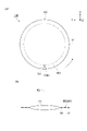
図10(a)及び図10(b)に示されるように、対象物100には、有効領域R及び除去領域Eが設定されている。有効領域Rは、取得する半導体デバイスに対応する部分である。ここでの有効領域Rは、対象物100を厚さ方向から見て中央部分を含む円板状の部分である。除去領域Eは、対象物100における有効領域Rよりも外側の領域である。除去領域Eは、対象物100において有効領域R以外の外縁部分である。ここでの除去領域Eは、有効領域Rを囲う円環状の部分である。除去領域Eは、対象物100を厚さ方向から見て周縁部分(外縁のベベル部)を含む。有効領域R及び除去領域Eの設定は、制御部9において行うことができる。有効領域R及び除去領域Eは、座標指定されたものであってもよい。 As shown in FIGS. 10A and 10B, an effective area R and a removal area E are set on the object 100. FIG. The effective area R is a portion corresponding to the semiconductor device to be acquired. The effective region R here is a disk-shaped portion including the central portion when the object 100 is viewed from the thickness direction. The removal area E is an area outside the effective area R of the object 100 . The removal area E is an outer edge portion other than the effective area R in the object 100 . The removal area E here is an annular portion surrounding the effective area R. As shown in FIG. The removal region E includes a peripheral edge portion (outer edge bevel portion) when the object 100 is viewed from the thickness direction. The effective area R and the removal area E can be set by the controller 9 . The valid area R and the removal area E may be coordinate-specified.

ステージ107は、対象物100が載置される支持部である。ステージ107は、上記支持部7(図1参照)と同様に構成されている。本実施形態のステージ107には、対象物100の裏面100bをレーザ光入射面側である上側にした状態(表面100aをステージ107側である下側にした状態)で、対象物100が載置されている。ステージ107は、その中心に設けられた回転軸Cを有する。回転軸Cは、Z方向に沿って延びる軸である。ステージ107は、回転軸Cを中心に回転可能である。ステージ107は、モータ等の公知の駆動装置の駆動力により回転駆動される。 The stage 107 is a support on which the object 100 is placed. The stage 107 is constructed in the same manner as the support section 7 (see FIG. 1). The object 100 is placed on the stage 107 of the present embodiment with the back surface 100b of the object 100 facing upward, which is the side of the laser light incident surface (with the front surface 100a facing downward, which is the stage 107 side). It is The stage 107 has a rotation axis C provided at its center. The rotation axis C is an axis extending along the Z direction. The stage 107 is rotatable around the rotation axis C. As shown in FIG. The stage 107 is rotationally driven by a driving force of a known driving device such as a motor.

第1レーザ加工ヘッド10Aは、ステージ107に載置された対象物100に第1レーザ光L1をZ方向に沿って照射し、当該対象物100の内部に改質領域を形成する。第1レーザ加工ヘッド10Aは、第1Z軸レール106A及びX軸レール108に取り付けられている。第1レーザ加工ヘッド10Aは、モータ等の公知の駆動装置の駆動力により、第1Z軸レール106Aに沿ってZ方向に直線的に移動可能である。第1レーザ加工ヘッド10Aは、モータ等の公知の駆動装置の駆動力により、X軸レール108に沿ってX方向に直線的に移動可能である。第1レーザ加工ヘッド10Aは、照射部を構成する。 The first laser processing head 10A irradiates the object 100 placed on the stage 107 with the first laser beam L1 along the Z direction to form a modified region inside the object 100 . The first laser processing head 10A is attached to a first Z-axis rail 106A and an X-axis rail 108. As shown in FIG. The first laser processing head 10A is linearly movable in the Z direction along the first Z-axis rail 106A by the driving force of a known driving device such as a motor. The first laser processing head 10A is linearly movable in the X direction along the X-axis rail 108 by a driving force of a known driving device such as a motor. The first laser processing head 10A constitutes an irradiation section.

第1レーザ加工ヘッド10Aは、上述したように、反射型空間光変調器34を備えている。反射型空間光変調器34は、第1レーザ光L1の光軸に垂直な面内における集光点の形状(以下、「ビーム形状」ともいう)を成形する成形部を構成する。反射型空間光変調器34は、ビーム形状が長手方向を有するように第1レーザ光L1を成形する。例えば反射型空間光変調器34は、ビーム形状を楕円形状とする変調パターンを液晶層に表示させることで、ビーム形状を楕円形状へ成形する。 The first laser processing head 10A includes the reflective spatial light modulator 34 as described above. The reflective spatial light modulator 34 constitutes a shaping section that shapes the shape of the focal point (hereinafter also referred to as “beam shape”) in the plane perpendicular to the optical axis of the first laser beam L1. The reflective spatial light modulator 34 shapes the first laser light L1 so that the beam shape has a longitudinal direction. For example, the reflective spatial light modulator 34 forms the beam shape into an elliptical shape by causing the liquid crystal layer to display a modulation pattern that makes the beam shape an elliptical shape.

ビーム形状は、楕円形状に限定されず、長尺形状であればよい。ビーム形状は、扁平円形状、長円形状又はトラック形状であってもよい。ビーム形状は、長尺な三角形形状、矩形形状又は多角形形状であってもよい。このようなビーム形状を実現する反射型空間光変調器34の変調パターンは、スリットパターン及び非点パターンの少なくとも何れかを含んでいてもよい。なお、第1レーザ光L1が非点収差等によって複数の集光点を有する場合、複数の集光点のうち、第1レーザ光L1の光路における最も上流側の集光点の形状が、本実施形態のビーム形状である(その他のレーザ光において同じ)。ここでの長手方向は、ビーム形状に係る楕円形状の長軸方向であり、楕円長軸方向とも称される。 The beam shape is not limited to an elliptical shape, and may be any long shape. The beam shape may be flat circular, oval or track shaped. The beam shape may be an elongated triangular, rectangular or polygonal shape. The modulation pattern of the reflective spatial light modulator 34 that achieves such a beam shape may include at least one of a slit pattern and an astigmatic pattern. When the first laser beam L1 has a plurality of condensing points due to astigmatism or the like, the shape of the most upstream condensing point in the optical path of the first laser beam L1 among the plurality of condensing points is the same as that of the present invention. It is the beam shape of the embodiment (same for other laser beams). The longitudinal direction here is the major axis direction of the elliptical shape related to the beam shape, and is also called the major axis direction of the ellipse.

ビーム形状は、集光点の形状に限定されず、集光点付近の形状であってもよく、要は、集光領域(集光する領域)の一部の形状であればよい。例えば、非点収差を有する第1レーザ光L1の場合、図71(a)に示されるように、集光点付近におけるレーザ光入射面側の領域では、ビーム形状71が長手方向NHを有する。図71(a)のビーム形状71の平面内(集光点付近におけるレーザ光入射面側のZ方向位置での平面内)のビーム強度分布では、長手方向NHに強い強度を持つ分布になっており、ビーム強度の強い方向が長手方向NHと一致している。 The shape of the beam is not limited to the shape of the condensing point, and may be the shape of the vicinity of the condensing point. For example, in the case of the first laser beam L1 having astigmatism, as shown in FIG. 71(a), the beam shape 71 has the longitudinal direction NH in the area near the focal point on the side of the laser beam incidence surface. In the beam intensity distribution in the plane of the beam shape 71 in FIG. 71(a) (in the plane at the Z-direction position on the side of the laser beam incident surface near the focal point), the intensity is strong in the longitudinal direction NH. , and the direction in which the beam intensity is strong coincides with the longitudinal direction NH.

非点収差を有する第1レーザ光L1の場合、図71(c)に示されるように、集光点付近におけるレーザ光入射面の反対面側の領域では、ビーム形状71が、レーザ光入射面側の領域の長手方向NH(図71(a)参照)に対して垂直な長手方向NH0を有する。図71(c)のビーム形状71の平面内(集光点付近におけるレーザ光入射面の反対面側のZ方向位置での平面内)のビーム強度分布では、長手方向NH0に強い強度を持つ分布になっており、ビーム強度の強い方向が長手方向NH0と一致している。非点収差を有する第1レーザ光L1の場合、図71(b)に示されるように、集光点付近におけるレーザ光入射面側とその反対面側との間の領域では、ビーム形状71が長手方向を有さずに円形となる。 In the case of the first laser beam L1 having astigmatism, as shown in FIG. 71(c), in the region on the side opposite to the laser beam incidence surface near the condensing point, the beam shape 71 corresponds to the laser beam incidence surface. It has a longitudinal direction NH0 perpendicular to the longitudinal direction NH of the side region (see FIG. 71(a)). In the beam intensity distribution in the plane of the beam shape 71 in FIG. 71(c) (in the plane at the Z-direction position on the opposite side of the laser beam incident surface near the condensing point), the distribution has a strong intensity in the longitudinal direction NH0. , and the direction in which the beam intensity is strong coincides with the longitudinal direction NH0. In the case of the first laser beam L1 having astigmatism, as shown in FIG. 71(b), the beam shape 71 is changed in the region between the laser beam incident surface side and the opposite surface side in the vicinity of the focal point. It is circular with no longitudinal direction.

このような非点収差を有する第1レーザ光L1の場合において、本実施形態が対象とする集光領域の一部は、集光点付近におけるレーザ光入射面側の領域を含み、本実施形態が対象とするビーム形状は、図71(a)に示されるビーム形状71である。 In the case of the first laser beam L1 having such astigmatism, a part of the condensing region targeted by the present embodiment includes a region near the condensing point on the side of the laser light incident surface. The target beam shape is the beam shape 71 shown in FIG. 71(a).

なお、反射型空間光変調器34の変調パターンを調整することによって、集光領域における図71(a)に示されるビーム形状71となる位置を、所望に制御することができる。例えば、集光点付近におけるレーザ光入射面の反対面側の領域にて図71(a)に示されるビーム形状71を有するように制御することができる。また例えば、集光点付近におけるレーザ光入射面側とその反対面側との間の領域にて図71(a)に示されるビーム形状71を有するように制御することができる。集光領域の一部の位置は、特に限定されず、対象物100のレーザ光入射面からその反対面までの間の何れかの位置であればよい。 By adjusting the modulation pattern of the reflective spatial light modulator 34, the position of the beam shape 71 shown in FIG. 71(a) in the converging area can be controlled as desired. For example, it is possible to control the region on the opposite side of the laser beam incident surface near the focal point to have the beam shape 71 shown in FIG. 71(a). Further, for example, it is possible to control so as to have a beam shape 71 shown in FIG. The position of the part of the condensing area is not particularly limited, and may be any position between the laser light incident surface of the object 100 and the opposite surface thereof.

また例えば、変調パターンの制御及び/又は機械式機構によるスリット又は楕円光学系を用いた場合、図72(a)に示されるように、集光点付近におけるレーザ光入射面側の領域では、ビーム形状71が長手方向NHを有する。図72(a)のビーム形状71の平面内(集光点付近におけるレーザ光入射面側のZ方向位置での平面内)のビーム強度分布では、長手方向NHに強い強度を持つ分布になっており、ビーム強度の強い方向が長手方向NHと一致している。 Further, for example, when a slit or an elliptical optical system by modulation pattern control and/or a mechanical mechanism is used, as shown in FIG. Shape 71 has a longitudinal direction NH. In the beam intensity distribution in the plane of the beam shape 71 in FIG. 72(a) (in the plane at the Z-direction position on the side of the laser beam incident surface near the focal point), the intensity is strong in the longitudinal direction NH. , and the direction in which the beam intensity is strong coincides with the longitudinal direction NH.

スリット又は楕円光学系を用いた場合、図72(c)に示されるように、集光点付近におけるレーザ光入射面の反対面側の領域では、ビーム形状71が、レーザ光入射面側の領域の長手方向NH(図71(a)参照)と同じ長手方向NHを有する。図72(c)のビーム形状71の平面内(集光点付近におけるレーザ光入射面の反対面側のZ方向位置での平面内)のビーム強度分布では、長手方向NHに強い強度を持つ分布になっており、ビーム強度の強い方向が長手方向NHと一致している。スリット又は楕円光学系を用いた場合、図72(b)に示されるように、集光点では、ビーム形状71が、レーザ光入射面側の領域の長手方向NH(図72(a)参照)に対して垂直な長手方向NH0を有する。図72(b)のビーム形状71の平面内(集光点のZ方向位置での平面内)のビーム強度分布では、長手方向NH0に強い強度を持つ分布になっており、ビーム強度の強い方向が長手方向NH0と一致している。 When a slit or elliptical optical system is used, as shown in FIG. has the same longitudinal direction NH as the longitudinal direction NH of (see FIG. 71(a)). In the beam intensity distribution in the plane of the beam shape 71 in FIG. 72(c) (in the plane at the Z-direction position on the opposite side of the laser beam incident surface near the condensing point), a distribution with strong intensity in the longitudinal direction NH , and the direction in which the beam intensity is strong coincides with the longitudinal direction NH. When a slit or an elliptical optical system is used, as shown in FIG. 72(b), at the focal point, the beam shape 71 extends along the longitudinal direction NH of the region on the side of the laser light incident surface (see FIG. 72(a)). has a longitudinal direction NH0 perpendicular to . In the beam intensity distribution in the plane of the beam shape 71 in FIG. 72(b) (in the plane at the Z-direction position of the focal point), the intensity is strong in the longitudinal direction NH0. coincides with the longitudinal direction NH0.

このようなスリット又は楕円光学系を用いた場合には、集光点以外のビーム形状71が長手方向を有する形状となり、集光点以外のビーム形状71は、本実施形態が対象とするビーム形状である。すなわち、本実施形態が対象とする集光領域の一部は、集光点付近におけるレーザ光入射面側の領域を含み、本実施形態が対象とするビーム形状は、図72(a)に示されるビーム形状71である。 When such a slit or elliptical optical system is used, the beam shape 71 other than the condensing point has a longitudinal direction, and the beam shape 71 other than the condensing point is the beam shape targeted by this embodiment. is. That is, part of the light condensing region targeted by this embodiment includes the region on the side of the laser light incident surface near the condensing point, and the beam shape targeted by this embodiment is shown in FIG. is the beam shape 71 that is

第1レーザ加工ヘッド10Aは、測距センサ36を備えている。測距センサ36は、対象物100のレーザ光入射面に対して測距用レーザ光を出射し、当該レーザ光入射面によって反射された測距用の光を検出することで、対象物100のレーザ光入射面の変位データを取得する。測距センサ36としては、第1レーザ光L1と別軸のセンサである場合、三角測距方式、レーザ共焦点方式、白色共焦点方式、分光干渉方式、非点収差方式等のセンサを利用することができる。測距センサ36としては、第1レーザ光L1と同軸のセンサである場合、非点収差方式等のセンサを利用することができる。第1レーザ加工ヘッド10Aの回路部19(図3参照)は、測距センサ36で取得した変位データに基づいて、集光部14がレーザ光入射面に追従するように駆動部18(図5参照)を駆動させる。これにより、対象物100のレーザ光入射面と第1レーザ光L1の集光点である第1集光点との距離が一定に維持されるように、当該変位データに基づき集光部14がZ方向に沿って移動する。このような測距センサ36及びその制御(以下、「追従制御」ともいう)については、他のレーザ加工ヘッドにおいても同様である。 The first laser processing head 10A has a distance sensor 36 . The distance measuring sensor 36 emits a laser beam for distance measurement to the laser beam incident surface of the object 100 and detects the light for distance measurement reflected by the laser beam entrance surface to detect the distance of the object 100. Acquire the displacement data of the laser light incident surface. As the distance measuring sensor 36, if the sensor has a different axis from that of the first laser beam L1, a sensor of a triangular distance measuring method, a laser confocal method, a white light confocal method, a spectral interference method, an astigmatism method, or the like is used. be able to. As the distance measuring sensor 36, if it is a sensor coaxial with the first laser beam L1, an astigmatic sensor or the like can be used. The circuit unit 19 (see FIG. 3) of the first laser processing head 10A controls the driving unit 18 (see FIG. 5) so that the light collecting unit 14 follows the laser beam incident surface based on the displacement data acquired by the distance measuring sensor 36. reference). As a result, the light collecting unit 14 is adjusted based on the displacement data so that the distance between the laser light incident surface of the object 100 and the first light collecting point, which is the light collecting point of the first laser light L1, is kept constant. Move along the Z direction. Such a distance measuring sensor 36 and its control (hereinafter also referred to as "following control") are the same for other laser processing heads.

第1Z軸レール106Aは、Z方向に沿って延びるレールである。第1Z軸レール106Aは、取付部65を介して第1レーザ加工ヘッド10Aに取り付けられている。第1Z軸レール106Aは、第1レーザ光L1の第1集光点がZ方向に沿って移動するように、第1レーザ加工ヘッド10AをZ方向に沿って移動させる。第1Z軸レール106Aは、上記移動機構6(図1参照)又は上記移動機構300(図8参照)のレールに対応する。第1Z軸レール106Aは、鉛直移動機構を構成する。 The first Z-axis rail 106A is a rail extending along the Z direction. The first Z-axis rail 106A is attached to the first laser processing head 10A via an attachment portion 65. As shown in FIG. The first Z-axis rail 106A moves the first laser processing head 10A along the Z direction so that the first focal point of the first laser beam L1 moves along the Z direction. The first Z-axis rail 106A corresponds to the rail of the moving mechanism 6 (see FIG. 1) or the moving mechanism 300 (see FIG. 8). The first Z-axis rail 106A constitutes a vertical movement mechanism.

X軸レール108は、X方向に沿って延びるレールである。X軸レール108は、第1及び第2Z軸レール106A,106Bのそれぞれに取り付けられている。X軸レール108は、第1レーザ光L1の第1集光点がX方向に沿って移動するように、第1レーザ加工ヘッド10AをX方向に沿って移動させる。X軸レール108は、第1集光点が回転軸C又はその付近を通過するように、第1レーザ加工ヘッド10Aを移動させる。X軸レール108は、上記移動機構6(図1参照)又は上記移動機構300(図8参照)のレールに対応する。X軸レール108は、水平移動機構を構成する。 The X-axis rail 108 is a rail extending along the X direction. The X-axis rail 108 is attached to each of the first and second Z-axis rails 106A, 106B. The X-axis rail 108 moves the first laser processing head 10A along the X direction so that the first focal point of the first laser beam L1 moves along the X direction. The X-axis rail 108 moves the first laser processing head 10A so that the first focal point passes through the rotation axis C or its vicinity. The X-axis rail 108 corresponds to the rail of the moving mechanism 6 (see FIG. 1) or the moving mechanism 300 (see FIG. 8). The X-axis rail 108 constitutes a horizontal movement mechanism.

アライメントカメラ110は、各種の調整に用いられる画像を取得するカメラである。アライメントカメラ110は、対象物100を撮像する。アライメントカメラ110は、第1レーザ加工ヘッド10Aが取り付けられた取付部65に設置されており、第1レーザ加工ヘッド10Aと同期して可動する。 The alignment camera 110 is a camera that acquires images used for various adjustments. The alignment camera 110 images the target object 100 . The alignment camera 110 is installed in the attachment part 65 to which the 1st laser processing head 10A was attached, and moves synchronizing with the 1st laser processing head 10A.

制御部9は、プロセッサ、メモリ、ストレージ及び通信デバイス等を含むコンピュータ装置として構成されている。制御部9では、メモリ等に読み込まれたソフトウェア(プログラム)が、プロセッサによって実行され、メモリ及びストレージにおけるデータの読み出し及び書き込み、並びに、通信デバイスによる通信が、プロセッサによって制御される。これにより、制御部9は、各種機能を実現する。 The control unit 9 is configured as a computer device including a processor, memory, storage, communication device, and the like. In the control unit 9, the software (program) loaded into the memory or the like is executed by the processor, and the reading and writing of data in the memory and storage and the communication by the communication device are controlled by the processor. Thereby, the control part 9 implement|achieves various functions.

制御部9は、ステージ107及び第1レーザ加工ヘッド10Aを制御する。制御部9は、ステージ107の回転、第1レーザ加工ヘッド10Aからの第1レーザ光L1の照射、ビーム形状、及び、第1集光点の移動を制御する。制御部9は、ステージ107の回転量に関する回転情報(以下、「θ情報」ともいう)に基づいて、各種の制御を実行可能である。θ情報は、ステージ107を回転させる駆動装置の駆動量から取得されてもよいし、別途のセンサ等により取得されてもよい。θ情報は、公知の種々の手法により取得することができる。ここでのθ情報は、対象物100が0°方向の位置に位置するときの状態を基準にした回転角度を含む。 The controller 9 controls the stage 107 and the first laser processing head 10A. The controller 9 controls rotation of the stage 107, irradiation of the first laser beam L1 from the first laser processing head 10A, beam shape, and movement of the first focal point. The control unit 9 can perform various controls based on rotation information (hereinafter also referred to as “θ information”) regarding the amount of rotation of the stage 107 . The θ information may be acquired from the driving amount of the driving device that rotates the stage 107, or may be acquired by a separate sensor or the like. θ information can be obtained by various known techniques. The θ information here includes the rotation angle based on the state when the object 100 is positioned in the direction of 0°.

制御部9は、ステージ107を回転させながら、対象物100におけるラインM3(有効領域Rの周縁)に沿った位置に第1集光点を位置させた状態で、θ情報に基づいて第1レーザ加工ヘッド10Aにおける第1レーザ光L1の照射の開始及び停止を制御することにより、有効領域Rの周縁に沿って改質領域を形成させる周縁処理を実行する。 While rotating the stage 107, the control unit 9 positions the first focal point at a position along the line M3 (periphery of the effective area R) on the object 100, and operates the first laser beam based on the θ information. By controlling the start and stop of the irradiation of the first laser beam L1 in the processing head 10A, edge processing for forming a modified area along the edge of the effective area R is performed.

制御部9は、ステージ107を回転させずに、除去領域Eに第1レーザ光L1を照射させると共に、当該第1レーザ光L1の第1集光点を移動させることにより、除去領域Eに改質領域を形成させる除去処理を実行する。 Without rotating the stage 107, the control unit 9 irradiates the removal region E with the first laser beam L1 and moves the first condensing point of the first laser beam L1, thereby changing the removal region E. Perform a removal process that creates textured regions.

制御部9は、改質領域に含まれる複数の改質スポットのピッチ(加工進行方向に隣接する改質スポットの間隔)が一定になるように、ステージ107の回転、第1レーザ加工ヘッド10Aからの第1レーザ光L1の照射、並びに、第1集光点の移動の少なくとも何れかを制御する。 The control unit 9 rotates the stage 107 and rotates the first laser processing head 10A so that the pitch of the plurality of modified spots included in the modified region (interval between adjacent modified spots in the processing progress direction) is constant. and at least one of the movement of the first focal point and the irradiation of the first laser beam L1.

制御部9は、アライメントカメラ110の撮像画像から、対象物100の回転方向の基準位置(0°方向の位置)及び対象物100の直径を取得する。制御部9は、第1レーザ加工ヘッド10Aがステージ107の回転軸C上までX軸レール108に沿って移動できるように、第1レーザ加工ヘッド10Aの移動を制御する。 The control unit 9 acquires the reference position (0° direction position) of the object 100 in the rotational direction and the diameter of the object 100 from the image captured by the alignment camera 110 . The control unit 9 controls movement of the first laser processing head 10A so that the first laser processing head 10A can move along the X-axis rail 108 to the rotation axis C of the stage 107 .

次に、レーザ加工装置101を用いて、対象物100にトリミング加工を施し、半導体デバイスを取得(製造)する方法の一例について、以下に説明する。 Next, an example of a method for obtaining (manufacturing) a semiconductor device by performing a trimming process on the object 100 using the laser processing apparatus 101 will be described below.

まず、裏面100bをレーザ光入射面側にした状態でステージ107上に対象物100を載置する。対象物100において機能素子が搭載された表面100a側は、支持基板ないしテープ材が接着されて保護されている。 First, the object 100 is placed on the stage 107 with the back surface 100b facing the laser beam incident surface. The surface 100a side of the object 100 on which the functional element is mounted is protected by adhering a support substrate or tape material.

続いて、トリミング加工を実施する。トリミング加工では、制御部9により周縁処理を実行する。具体的には、図11(a)に示されるように、ステージ107を一定の回転速度で回転しながら、対象物100における有効領域Rの周縁に沿った位置に第1集光点(集光点)P1を位置させた状態で、θ情報に基づいて第1レーザ加工ヘッド10Aにおける第1レーザ光L1の照射の開始及び停止を制御する。これにより、図11(b)及び11(c)に示されるように、ラインM3(有効領域Rの周縁)に沿って改質領域4を形成する。形成した改質領域4は、改質スポット及び改質スポットから延びる亀裂を含む。 Then, trimming is performed. In the trimming process, the control unit 9 executes edge processing. Specifically, as shown in FIG. 11A, while rotating the stage 107 at a constant rotational speed, the first condensing point (condensing With the point P1 positioned, the start and stop of irradiation of the first laser beam L1 in the first laser processing head 10A are controlled based on the θ information. Thereby, as shown in FIGS. 11(b) and 11(c), the modified region 4 is formed along the line M3 (periphery of the effective region R). The modified region 4 formed includes modified spots and cracks extending from the modified spots.

トリミング加工では、制御部9により除去処理を実行する。具体的には、図12(a)に示されるように、ステージ107を回転させずに、除去領域Eにおいて第1レーザ光L1を照射すると共に、第1レーザ加工ヘッド10AをX軸レール108に沿って互いに離れる方向に移動し、当該第1レーザ光L1の第1集光点P1を対象物100の中心から離れる方向に移動する。ステージ107を90°回転させた後、除去領域Eにおいて第1レーザ光L1を照射すると共に、第1レーザ加工ヘッド10AをX軸レール108に沿って互いに離れる方向に移動し、当該第1レーザ光L1の第1集光点P1を対象物100の中心から離れる方向に移動する。 In the trimming process, the control unit 9 executes removal processing. Specifically, as shown in FIG. 12A, the first laser beam L1 is applied to the removal area E without rotating the stage 107, and the first laser processing head 10A is moved to the X-axis rail 108. , and the first condensing point P1 of the first laser beam L1 moves away from the center of the object 100. As shown in FIG. After rotating the stage 107 by 90°, the removal area E is irradiated with the first laser beam L1, and the first laser processing head 10A is moved along the X-axis rail 108 in a direction away from each other, and the first laser beam The first converging point P1 of L1 is moved away from the center of the object 100 .

これにより、図12(b)に示されるように、Z方向から見て除去領域Eに4等分するように延びるラインに沿って、改質領域4を形成する。形成した改質領域4は、改質スポット及び改質スポットから延びる亀裂を含む。この亀裂は、表面100a及び裏面100bの少なくとも何れかに到達していてもよいし、表面100a及び裏面100bの少なくとも何れかに到達していなくてもよい。その後、図13(a)及び図13(b)に示されるように、例えば冶具又はエアーにより、改質領域4を境界として除去領域Eを取り除く。 As a result, as shown in FIG. 12(b), the modified region 4 is formed along the line extending so as to divide the removed region E into four equal parts when viewed in the Z direction. The modified region 4 formed includes modified spots and cracks extending from the modified spots. The crack may reach at least one of the front surface 100a and the back surface 100b, or may not reach at least one of the front surface 100a and the back surface 100b. After that, as shown in FIGS. 13(a) and 13(b), the removed region E is removed with the modified region 4 as a boundary, for example, using a jig or air.

続いて、図13(c)に示されるように、対象物100の剥離面100hに対して仕上げの研削、ないし砥石等の研磨材KMによる研磨を行う。エッチングにより対象物100を剥離している場合、当該研磨を簡略化することができる。以上の結果、半導体デバイス100Kが取得される。 Subsequently, as shown in FIG. 13C, the peeled surface 100h of the object 100 is subjected to finish grinding or polishing with an abrasive material KM such as a whetstone. When the object 100 is removed by etching, the polishing can be simplified. As a result, the semiconductor device 100K is obtained.

次に、本実施形態のトリミング加工に関して、より詳細に説明する。 Next, the trimming process of this embodiment will be described in more detail.

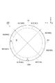
図14に示されるように、対象物100は、板状を呈し、その主面として表面100a及び裏面100b(図10参照)を有する。対象物100は、(100)面を主面とするウェハである。対象物100は、シリコンで形成されたシリコンウェハである。対象物100は、一方の(110)面に垂直な第1結晶方位K1と、他方の(110)面に垂直な第2結晶方位K2と、を有する。(110)面は、へき開面である。第1結晶方位K1及び第2結晶方位K2は、へき開方向、すなわち、対象物100において最も亀裂が延びやすい方向である。第1結晶方位K1と第2結晶方位K2とは、互いに直交する。 As shown in FIG. 14, the target object 100 has a plate shape and has a front surface 100a and a back surface 100b (see FIG. 10) as its principal surfaces. A target object 100 is a wafer whose main surface is the (100) plane. The object 100 is a silicon wafer made of silicon. The object 100 has a first crystal orientation K1 perpendicular to one (110) plane and a second crystal orientation K2 perpendicular to the other (110) plane. The (110) plane is a cleavage plane. The first crystal orientation K1 and the second crystal orientation K2 are cleavage directions, that is, directions in which cracks are most likely to extend in the object 100 . The first crystal orientation K1 and the second crystal orientation K2 are orthogonal to each other.

対象物100には、アライメント対象100nが設けられている。例えばアライメント対象100nは、対象物100の0°方向の位置に対してθ方向(ステージ107の回転軸C回りの回転方向)に一定の関係を有する。0°方向の位置とは、θ方向において基準となる対象物100の位置である。例えばアライメント対象100nは、外縁部に形成されたノッチである。なお、アライメント対象100nは、特に限定されず、対象物100のオリエンテーションフラットであってもよいし、機能素子のパターンであってもよい。図示する例では、アライメント対象100nは、対象物100の0°方向の位置に設けられている。換言すると、アライメント対象100nは、対象物100における第2結晶方位K2の方向に延びる直径上の位置に設けられている。 The object 100 is provided with an alignment object 100n. For example, the alignment target 100n has a certain relationship in the θ direction (rotation direction about the rotation axis C of the stage 107) with respect to the position of the target 100 in the 0° direction. The position in the 0° direction is the position of the object 100 that serves as a reference in the θ direction. For example, the alignment target 100n is a notch formed in the outer edge. The alignment target 100n is not particularly limited, and may be an orientation flat of the target 100 or a pattern of functional elements. In the illustrated example, the alignment target 100n is provided at the position of the target 100 in the 0° direction. In other words, the alignment target 100n is provided at a position on the diameter of the target 100 extending in the direction of the second crystal orientation K2.

対象物100には、トリミング予定ラインとしてのラインM3が設定されている。ラインM3は、改質領域4の形成を予定するラインである。ラインM3は、対象物100の外縁の内側において環状に延在する。ここでのラインM3は、円環状に延在する。ラインM3は、対象物100の有効領域Rと除去領域Eとの境界に設定されている。ラインM3の設定は、制御部9において行うことができる。ラインM3は、仮想的なラインであるが、実際に引かれたラインであってもよい。ラインM3は、座標指定されたものであってもよい。 A line M3 is set on the object 100 as a line to be trimmed. A line M3 is a line on which the modified region 4 is to be formed. The line M3 extends annularly inside the outer edge of the object 100 . The line M3 here extends in an annular shape. A line M3 is set at the boundary between the effective area R and the removal area E of the object 100 . The setting of the line M3 can be performed in the control section 9. FIG. The line M3 is a virtual line, but it may be an actually drawn line. The line M3 may be coordinate-specified.

図9に示されるように、レーザ加工装置101の制御部9は、取得部9a、決定部9b、加工制御部9c、及び調整部9dを有している。取得部9aは、対象物100に関する対象物情報を取得する。対象物情報は、例えば対象物100の結晶方位(第1結晶方位K1及び第2結晶方位K2)に関する情報と、対象物100の0°方向の位置及び対象物100の直径に関するアライメント情報と、を含む。を含む。取得部9aは、アライメントカメラ110の撮像画像、並びに、ユーザの操作又は外部からの通信等による入力に基づいて、対象物情報を取得することができる。 As shown in FIG. 9, the control unit 9 of the laser processing device 101 has an acquisition unit 9a, a determination unit 9b, a processing control unit 9c, and an adjustment unit 9d. The acquisition unit 9 a acquires object information about the object 100 . The object information includes, for example, information about the crystal orientation of the object 100 (the first crystal orientation K1 and the second crystal orientation K2), and alignment information about the position of the object 100 in the 0° direction and the diameter of the object 100. include. including. The acquisition unit 9a can acquire target object information based on the image captured by the alignment camera 110 and an input by a user's operation, communication from the outside, or the like.

取得部9aは、ラインM3に関するライン情報を取得する。ライン情報は、ラインM3の情報、及び、ラインM3に沿って第1集光点P1を相対的に移動させる場合の当該移動の移動方向(「加工進行方向」ともいう)に関する情報を含む。例えば加工進行方向は、ラインM3上に位置する第1集光点P1を通るラインM3の接線方向である。取得部9aは、ユーザの操作又は外部からの通信等による入力に基づいて、ライン情報を取得することができる。 The acquisition unit 9a acquires line information about the line M3. The line information includes information on the line M3 and information on the direction of movement (also referred to as "processing direction") when the first focal point P1 is relatively moved along the line M3. For example, the processing progress direction is the tangential direction of the line M3 passing through the first condensing point P1 located on the line M3. The acquisition unit 9a can acquire line information based on an input by a user's operation or communication from the outside.

決定部9bは、取得部9aによって取得された対象物情報及びライン情報に基づいて、ビーム形状の長手方向が加工進行方向と交差するように、ラインM3に沿って第1集光点P1を相対的に移動させる場合の長手方向の向きを決定する。具体的には、決定部9bは、対象物情報及びライン情報に基づいて、長手方向NHの向きを第1向き及び第2向きに決定する。第1向きは、ラインM3の第1領域M31に沿って第1集光点P1を相対的に移動させる場合のビーム形状の長手方向の向きである。第2向きは、ラインM3の第2領域M32に沿って第1集光点P1を相対的に移動させる場合のビーム形状の長手方向の向きである。以下、「ビーム形状の長手方向の向き」を、単に「ビーム形状の向き」ともいう。 Based on the object information and the line information acquired by the acquisition unit 9a, the determination unit 9b moves the first condensing point P1 along the line M3 so that the longitudinal direction of the beam shape intersects the processing progress direction. Determines the longitudinal orientation of the vertical movement. Specifically, the determination unit 9b determines the orientation of the longitudinal direction NH to be the first orientation and the second orientation based on the target object information and the line information. The first direction is the longitudinal direction of the beam shape when the first focal point P1 is relatively moved along the first region M31 of the line M3. The second direction is the longitudinal direction of the beam shape when the first focal point P1 is relatively moved along the second region M32 of the line M3. Hereinafter, the "longitudinal direction of the beam shape" is also simply referred to as the "beam shape direction."

第1領域M31は、ラインM3が対象物100の第2結晶方位K2と直交する1点を0°の点とした場合に、0°の点から45°の点の前までの間の部分、90°の点から135°の点の前までの間の部分、180°の点から225°の点の前までの間の部分、及び270°の点から315°の点の前までの間の部分を含む。第2領域M32は、ラインM3が対象物100の第2結晶方位K2と直交する1点を0°の点とした場合に、45°の点から90°の点の前までの間の部分、135°の点から180°の点の前までの間の部分、225°の点から270°の点の前までの間の部分、及び315°の点から360°の点の前までの間の部分を含む。以下、このようなラインM3上における各点の角度の定義について同様である。 The first region M31 is a portion between the 0° point and the front of the 45° point, where the point where the line M3 intersects the second crystal orientation K2 of the target object 100 is the 0° point. The portion between the 90° point and before the 135° point, the portion between the 180° point and before the 225° point, and the portion between the 270° point and before the 315° point Including part. The second region M32 is a portion between a point of 45° and a point before the point of 90° when one point where the line M3 intersects the second crystal orientation K2 of the target object 100 is the point of 0°. The portion between the 135° point and before the 180° point, the portion between the 225° point and before the 270° point, and the portion between the 315° point and before the 360° point Including part. Hereinafter, the definition of the angle of each point on the line M3 is the same.

第1領域M31は、ラインM3に沿って第1集光点P1を相対的に移動させる場合に、後述の加工角度が0°以上45°未満もしくは-90°以上-45°未満となる領域を含む。第2領域M32は、ラインM3に沿って第1集光点P1を相対的に移動させる場合に、後述の加工角度が45°以上90°未満もしくは-45°以上0°未満となる領域を含む。ちなみに、ラインM3における第1領域M31及び第2領域M32のそれぞれは、後述の第4実施形態の第1部分に対応する。 The first region M31 is a region where the processing angle described later is 0° or more and less than 45° or -90° or more and less than -45° when the first focal point P1 is relatively moved along the line M3. include. The second region M32 includes a region where the processing angle described later is 45° or more and less than 90° or -45° or more and less than 0° when the first converging point P1 is relatively moved along the line M3. . Incidentally, each of the first region M31 and the second region M32 in the line M3 corresponds to the first portion of the fourth embodiment described later.

図15(b)に示されるように、加工角度αは、第1結晶方位K1に対する加工進行方向BDの角度である。加工角度αは、レーザ光入射面である裏面100bから見て、反時計回りに向かう角度を正(プラス)の角度とし、時計回りに向かう角度を負(マイナス)の角度とする。加工角度αは、ステージ107のθ情報、対象物情報及びライン情報に基づき取得できる。第1領域M31に沿って第1集光点P1を相対的に移動している場合は、加工角度αが0°以上45°未満もしくは-90°以上-45°未満の場合として認識することができる。第2領域M32に沿って第1集光点P1を相対的に移動する場合は、加工角度αが45°以上90°未満もしくは-45°以上0°未満の場合として認識することができる。 As shown in FIG. 15(b), the processing angle α is the angle of the processing progress direction BD with respect to the first crystal orientation K1. The processing angle α is defined as a positive (plus) angle when viewed from the rear surface 100b, which is the laser light incident surface, in a counterclockwise direction, and a negative (minus) angle in a clockwise direction. The processing angle α can be acquired based on the θ information of the stage 107, the object information, and the line information. When the first converging point P1 is relatively moved along the first region M31, it can be recognized as the case where the processing angle α is 0° or more and less than 45° or -90° or more and less than -45°. can. When the first focal point P1 is relatively moved along the second region M32, it can be recognized as a case where the processing angle α is 45° or more and less than 90° or −45° or more and less than 0°.

第1向き及び第2向きは、第1結晶方位K1及び第2結晶方位K2のうち加工進行方向BDとの間の角度が大きい一方(より離れている一方)に近づくように、加工進行方向BDに対して傾斜した方向の向きである。 The first orientation and the second orientation are set so as to approach one of the first crystal orientation K1 and the second crystal orientation K2 that has a larger angle with the processing direction BD (the one that is farther apart). is the orientation in a direction oblique to

第1向き及び第2向きは、加工角度αが0°以上90°未満の場合、次のとおりである。第1向きは、第2結晶方位K2に近づく側へ長手方向NHが加工進行方向BDに対して傾斜した方向の向きである。第2向きは、第1結晶方位K1に近づく側へ長手方向NHが加工進行方向BDに対して傾斜した方向の向きである。第1向きは、加工進行方向BDから第2結晶方位K2に近づく側へ10°~35°傾斜した方向の向きである。第2向きは、加工進行方向BDから第1結晶方位K1に近づく側へ10°~35°傾斜した方向の向きである。 The first orientation and the second orientation are as follows when the processing angle α is 0° or more and less than 90°. The first direction is the direction in which the longitudinal direction NH is inclined with respect to the processing progress direction BD toward the side approaching the second crystal orientation K2. The second direction is the direction in which the longitudinal direction NH is inclined with respect to the processing progress direction BD toward the side approaching the first crystal orientation K1. The first direction is a direction inclined by 10° to 35° from the processing direction BD toward the second crystal orientation K2. The second direction is a direction inclined by 10° to 35° from the processing direction BD toward the first crystal orientation K1.

第1向きは、ビーム角度βが+10°~+35°の場合のビーム形状71の向きである。第2向きは、ビーム角度βが-35°~-10°の場合のビーム形状71の向きである。ビーム角度βは、加工進行方向BDと長手方向NHとの間の角度である。ビーム角度βは、レーザ光入射面である裏面100bから見て、反時計回りに向かう角度を正(プラス)の角度とし、時計回りに向かう角度を負(マイナス)の角度とする。ビーム角度βは、ビーム形状71の向きと加工進行方向BDとに基づき取得できる。 The first orientation is the orientation of the beam shape 71 when the beam angle β is between +10° and +35°. The second orientation is the orientation of the beam shape 71 when the beam angle β is between -35° and -10°. The beam angle β is the angle between the processing progress direction BD and the longitudinal direction NH. The beam angle β is positive when viewed from the rear surface 100b, which is the laser light incident surface, in a counterclockwise direction, and is a negative angle in a clockwise direction. The beam angle β can be obtained based on the orientation of the beam shape 71 and the processing progress direction BD.

加工制御部9cは、対象物100に対するレーザ加工の開始及び停止を制御する。加工制御部9cは、ラインM3の第1領域M31に沿って第1集光点P1を相対的に移動させて改質領域4を形成させると共に、ラインM3の第1領域M31以外の領域での改質領域4の形成を停止させる第1処理を実行する。加工制御部9cは、ラインM3の第2領域M32に沿って第1集光点P1を相対的に移動させて改質領域4を形成させると共に、ラインM3の第2領域M32以外の領域での改質領域4の形成を停止させる第2処理と、を実行する。 The processing control unit 9c controls the start and stop of laser processing on the object 100 . The processing control unit 9c relatively moves the first condensing point P1 along the first region M31 of the line M3 to form the modified region 4, and also moves the region other than the first region M31 of the line M3. A first process for stopping the formation of the modified region 4 is performed. The processing control unit 9c relatively moves the first condensing point P1 along the second region M32 of the line M3 to form the modified region 4, and moves the region other than the second region M32 of the line M3. and a second process of stopping the formation of the modified region 4 .

加工制御部9cによる改質領域4の形成及びその停止の切り替えは、次のようにして実現することができる。例えば、第1レーザ加工ヘッド10Aにおいて、第1レーザ光L1の照射(出力)の開始及び停止(ON/OFF)を切替えることで、改質領域4の形成と当該形成の停止とを切り替えることが可能である。具体的には、レーザ発振器が固体レーザで構成されている場合、共振器内に設けられたQスイッチ(AOM(音響光学変調器)、EOM(電気光学変調器)等)のON/OFFが切り替えられることで、第1レーザ光L1の照射の開始及び停止が高速に切り替えられる。レーザ発振器がファイバレーザで構成されている場合、シードレーザ、アンプ(励起用)レーザを構成する半導体レーザの出力のON/OFFが切り替えられることで、第1レーザ光L1の照射の開始及び停止が高速に切り替えられる。レーザ発振器が外部変調素子を用いている場合、共振器外に設けられた外部変調素子(AOM、EOM等)のON/OFFが切り替えられることで、第1レーザ光L1の照射のON/OFFが高速に切り替えられる。 Formation of the modified region 4 by the processing control unit 9c and switching of stoppage thereof can be realized as follows. For example, in the first laser processing head 10A, by switching the start and stop (ON/OFF) of the irradiation (output) of the first laser beam L1, it is possible to switch between the formation of the modified region 4 and the stop of the formation. It is possible. Specifically, when the laser oscillator is composed of a solid-state laser, a Q switch (AOM (acousto-optic modulator), EOM (electro-optic modulator), etc.) provided in the resonator is switched ON/OFF. As a result, the start and stop of the irradiation of the first laser beam L1 can be switched at high speed. When the laser oscillator is composed of a fiber laser, the irradiation of the first laser beam L1 can be started and stopped by switching ON/OFF of the output of the semiconductor laser constituting the seed laser and amplifier (excitation) laser. High speed switching. When the laser oscillator uses an external modulation element, ON/OFF of the irradiation of the first laser beam L1 is turned on/off by switching ON/OFF of the external modulation element (AOM, EOM, etc.) provided outside the resonator. High speed switching.

或いは、加工制御部9cによる改質領域4の形成及びその停止の切り替えは、次のようにして実現してもよい。例えば、シャッタ等の機械式機構を制御するによって第1レーザ光L1の光路を開閉し、改質領域4の形成と当該形成の停止とを切り替えてもよい。第1レーザ光L1をCW光(連続波)へ切り替えることで、改質領域4の形成を停止させてもよい。反射型空間光変調器34の液晶層に、第1レーザ光L1の集光状態を改質できない状態とするパターン(例えば、レーザ散乱させる梨地模様のパターン)を表示することで、改質領域4の形成を停止させてもよい。アッテネータ等の出力調整部を制御し、改質領域が形成できないように第1レーザ光L1の出力に低下させることで、改質領域4の形成を停止させてもよい。偏光方向を切り替えることで、改質領域4の形成を停止させてもよい。第1レーザ光L1を光軸以外の方向に散乱させて(飛ばして)カットすることで、改質領域4の形成を停止させてもよい。 Alternatively, the formation and stop of the modified region 4 by the processing control unit 9c may be switched as follows. For example, the optical path of the first laser beam L1 may be opened and closed by controlling a mechanical mechanism such as a shutter to switch between forming the modified region 4 and stopping the formation. The formation of the modified region 4 may be stopped by switching the first laser beam L1 to CW light (continuous wave). By displaying on the liquid crystal layer of the reflective spatial light modulator 34 a pattern (for example, a satin pattern that causes laser scattering) that makes it impossible to modify the condensed state of the first laser beam L1, the modified region 4 may stop the formation of The formation of the modified region 4 may be stopped by controlling an output adjustment unit such as an attenuator and lowering the output of the first laser beam L1 so that the modified region cannot be formed. The formation of the modified region 4 may be stopped by switching the polarization direction. The formation of the modified region 4 may be stopped by scattering (flying) the first laser beam L1 in a direction other than the optical axis and cutting it.

調整部9dは、反射型空間光変調器34を制御することにより、ビーム形状71の向きを調整する。調整部9dは、加工制御部9cによって第1処理を実行する場合に、第1向きとなるようにビーム形状71の向きを調整する。調整部9dは、加工制御部9cによって第2処理を実行する場合に、第2向きとなるようにビーム形状71の向きを調整する。調整部9dは、加工進行方向BDに対して±35°の範囲で変化するように、ビーム形状71の長手方向NHを調整する。 The adjuster 9 d adjusts the direction of the beam shape 71 by controlling the reflective spatial light modulator 34 . The adjuster 9d adjusts the orientation of the beam shape 71 so as to be in the first orientation when the processing controller 9c executes the first process. The adjustment unit 9d adjusts the orientation of the beam shape 71 so as to have the second orientation when the processing control unit 9c executes the second process. The adjuster 9d adjusts the longitudinal direction NH of the beam shape 71 so as to vary within a range of ±35° with respect to the processing progress direction BD.

上述したレーザ加工装置101では、以下のトリミング加工(レーザ加工方法)を実施する。 The laser processing apparatus 101 described above performs the following trimming processing (laser processing method).

トリミング加工では、まず、アライメントカメラ110が対象物100のアライメント対象100nの直上に位置し且つアライメント対象100nにアライメントカメラ110のピントが合うように、ステージ107を回転させると共にアライメントカメラ110が搭載されている第1レーザ加工ヘッド10AをX軸レール108及び第1Z軸レール106Aに沿って移動させる。 In the trimming process, first, the stage 107 is rotated and the alignment camera 110 is mounted so that the alignment camera 110 is positioned directly above the alignment target 100n of the object 100 and the alignment camera 110 is focused on the alignment target 100n. The first laser processing head 10A is moved along the X-axis rail 108 and the first Z-axis rail 106A.

アライメントカメラ110により撮像を行う。アライメントカメラ110の撮像画像に基づいて、対象物100の0°方向の位置を取得する。取得部9aにより、アライメントカメラ110の撮像画像、並びに、ユーザの操作又は外部からの通信等による入力に基づいて、対象物情報及びライン情報を取得する(情報取得工程)。対象物情報は、対象物100の0°方向の位置及び直径に関するアライメント情報を含む。上述したように、アライメント対象100nは0°方向の位置に対してθ方向に一定の関係を有することから、撮像画像からアライメント対象100nの位置を得ることで、0°方向の位置を取得できる。アライメントカメラ110の撮像画像に基づくことで、対象物100の直径を取得できる。なお、対象物100の直径は、ユーザからの入力により設定されてもよい。 An image is captured by the alignment camera 110 . Based on the image captured by the alignment camera 110, the position of the object 100 in the 0° direction is acquired. The acquiring unit 9a acquires the target object information and the line information based on the image captured by the alignment camera 110 and the input by the user's operation or communication from the outside (information acquiring step). The object information includes alignment information regarding the position and diameter of the object 100 in the 0° direction. As described above, since the alignment target 100n has a certain relationship in the θ direction with respect to the position in the 0° direction, the position in the 0° direction can be obtained by obtaining the position of the alignment target 100n from the captured image. Based on the image captured by the alignment camera 110, the diameter of the target object 100 can be obtained. Note that the diameter of the target object 100 may be set by an input from the user.

取得された対象物情報及びライン情報に基づいて、決定部9bにより、ラインM3に沿って第1集光点P1を相対的に移動させる場合のビーム形状71の長手方向NHの向きとして第1向き及び第2向きを決定する(決定工程)。 Based on the acquired object information and line information, the determination unit 9b determines the first direction as the direction of the longitudinal direction NH of the beam shape 71 when the first condensing point P1 is relatively moved along the line M3. and a second orientation (determining step).

続いて、ステージ107を回転させ、対象物100を0°方向の位置に位置させる。X方向において、第1集光点P1がトリミング所定位置に位置するように、第1レーザ加工ヘッド10AをX軸レール108及び第1Z軸レール106Aに沿って移動させる。例えばトリミング所定位置は、対象物100におけるラインM3上の所定位置である。 Subsequently, the stage 107 is rotated to position the object 100 in the direction of 0°. In the X direction, the first laser processing head 10A is moved along the X-axis rail 108 and the first Z-axis rail 106A so that the first focal point P1 is located at the predetermined trimming position. For example, the predetermined trimming position is a predetermined position on line M3 on object 100 .

続いて、ステージ107の回転を開始する。測距センサによる裏面100bの追従を開始する。なお、測距センサの追従開始の前に、第1集光点P1の位置が測距センサの測長可能範囲内であることを予め確認する。ステージ107の回転速度が一定(等速)になった時点で、第1レーザ加工ヘッド10Aによる第1レーザ光L1の照射を開始する。 Subsequently, rotation of the stage 107 is started. Tracking of the rear surface 100b by the distance measuring sensor is started. It should be noted that before the tracking of the distance measuring sensor is started, it is confirmed in advance that the position of the first condensing point P1 is within the measurable range of the distance measuring sensor. When the rotation speed of the stage 107 becomes constant (constant speed), the irradiation of the first laser beam L1 by the first laser processing head 10A is started.

ステージ107を回転させながら、加工制御部9cにより第1レーザ光L1の照射のON/OFFを切り替えることで、図15(a)に示されるように、ラインM3のうち第1領域M31に沿って第1集光点P1を相対的に移動させて改質領域4を形成させると共に、ラインM3の第1領域M31以外の領域での改質領域4の形成を停止させる(第1加工工程)。図15(b)に示されるように、第1加工工程を実行する場合、調整部9dにより、第1向きとなるようにビーム形状71の向きを調整する。つまり、第1加工工程におけるビーム形状71の向きは、第1向きで固定されている。 While rotating the stage 107, by switching ON/OFF of irradiation of the first laser beam L1 by the processing control unit 9c, as shown in FIG. The first condensing point P1 is relatively moved to form the modified region 4, and the formation of the modified region 4 in the area other than the first area M31 of the line M3 is stopped (first processing step). As shown in FIG. 15(b), when performing the first processing step, the orientation of the beam shape 71 is adjusted by the adjuster 9d so as to be in the first orientation. That is, the orientation of the beam shape 71 in the first processing step is fixed at the first orientation.

続いて、ステージ107を回転させながら、加工制御部9cにより第1レーザ光L1の照射のON/OFFを切り替えることで、図16(a)に示されるように、ラインM3のうち第2領域M32に沿って第1集光点P1を相対的に移動させて改質領域4を形成させると共に、ラインM3の第1領域M31以外の領域での改質領域4の形成を停止させる(第2加工工程)。図16(b)に示されるように、第2加工工程を実行する場合、調整部9dにより、第2向きとなるようにビーム形状71の向きを調整する。つまり、第2加工工程におけるビーム形状71の向きは、第2向きで固定されている。 Subsequently, while rotating the stage 107, the ON/OFF of the irradiation of the first laser beam L1 is switched by the processing control unit 9c, so that the second region M32 of the line M3 is changed as shown in FIG. 16(a). along the line M3 to form the modified region 4, and stop the formation of the modified region 4 in the region other than the first region M31 of the line M3 (second processing process). As shown in FIG. 16(b), when performing the second processing step, the adjustment unit 9d adjusts the orientation of the beam shape 71 so as to be in the second orientation. That is, the orientation of the beam shape 71 in the second processing step is fixed at the second orientation.

上述した第1加工工程及び第2加工工程を、トリミング所定位置のZ方向位置を変えて繰り返し行う。以上により、対象物100の内部において、有効領域Rの周縁のラインM3に沿って、Z方向に複数列の改質領域4を形成する。 The above-described first processing step and second processing step are repeated by changing the Z-direction position of the predetermined trimming position. As described above, a plurality of rows of modified regions 4 are formed in the Z direction along the peripheral line M3 of the effective region R inside the object 100 .

以上、本実施形態のレーザ加工装置101では、ラインM3の第1領域M31に沿って第1集光点P1を相対的に移動させて改質領域4を形成させると共に、ラインM3の第1領域M31以外の領域での改質領域4の形成を停止させる第1処理を実行する。第1処理では、ビーム形状71の長手方向NHの向きが、加工進行方向BDと交差する向きであって対象物情報及びライン情報に基づいて決定された第1向きへ調整される。また、ラインM3の第2領域M32に沿って第1集光点P1を相対的に移動させて改質領域4を形成すると共に、ラインM3の第2領域M32以外の領域での改質領域4の形成を停止させる第2処理を実行する。第2処理では、ビーム形状71の長手方向NHの向きが、加工進行方向BDと交差する向きであって対象物情報及びライン情報に基づいて決定された第2向きへ調整される。したがって、長手方向NHが加工進行方向BDと一致した状態でラインM3に沿って第1集光点P1を相対的に移動させただけでは、例えば対象物100の物性に起因して第1領域M31及び第2領域M32のトリム面の品質が低下するような場合に、そのようなトリム面の品質の低下を抑制することができる。よって、レーザ加工装置101では、外縁部分である除去領域Eが除去された対象物100のトリム面の品質が場所によって低下するのを抑制することができる。 As described above, in the laser processing apparatus 101 of the present embodiment, the first focal point P1 is relatively moved along the first region M31 of the line M3 to form the modified region 4, and the first region of the line M3 A first process is performed to stop the formation of the modified region 4 in regions other than M31. In the first process, the orientation of the longitudinal direction NH of the beam shape 71 is adjusted to the first orientation that intersects with the processing advancing direction BD and is determined based on the object information and the line information. Further, along the second region M32 of the line M3, the first condensing point P1 is relatively moved to form the modified region 4, and the modified region 4 in the region other than the second region M32 of the line M3. A second process is performed to stop the formation of In the second process, the orientation of the longitudinal direction NH of the beam shape 71 is adjusted to a second orientation that intersects with the processing advancing direction BD and is determined based on the object information and the line information. Therefore, if the first condensing point P1 is relatively moved along the line M3 in a state where the longitudinal direction NH is aligned with the processing progress direction BD, for example, the physical properties of the object 100 may cause the first region M31 to And when the quality of the trimmed surface of the second region M32 deteriorates, such deterioration of the quality of the trimmed surface can be suppressed. Therefore, the laser processing apparatus 101 can prevent the quality of the trimmed surface of the object 100 from which the removal area E, which is the outer edge portion, has been removed from deteriorating depending on the location.

本実施形態のレーザ加工装置101によるレーザ加工方法では、ラインM3の第1領域M31に沿って第1集光点P1を相対的に移動させて改質領域4を形成すると共に、ラインM3の第1領域M31以外の領域では、改質領域4の形成を停止する第1加工工程を実施する。第1加工工程では、長手方向NHの向きが、加工進行方向BDと交差する向きであって対象物情報及びライン情報に基づいて決定された第1向きへ調整される。また、ラインM3の第2領域M32に沿って第1集光点P1を相対的に移動させて改質領域4を形成すると共に、ラインM3の第2領域M32以外の領域では、改質領域4の形成を停止する第2加工工程を実施する。第2加工工程では、長手方向NHの向きが、加工進行方向BDと交差する向きであって対象物情報及びライン情報に基づいて決定された第2向きへ調整される。したがって、ビーム形状71の長手方向NHが加工進行方向BDと一致した状態でラインM3に沿って第1集光点P1を相対的に移動させただけでは、例えば対象物100の物性に起因して第1領域M31及び第2領域M32のトリム面の品質が低下するような場合に、そのようなトリム面の品質の低下を抑制することができる。よって、レーザ加工装置101によるレーザ加工方法では、外縁部分である除去領域Eが除去された対象物100のトリム面の品質が、場所によって低下するのを抑制することができる。 In the laser processing method by the laser processing apparatus 101 of the present embodiment, the first focal point P1 is relatively moved along the first region M31 of the line M3 to form the modified region 4, and In regions other than the one region M31, a first processing step is performed to stop the formation of the modified region 4 . In the first machining step, the orientation of the longitudinal direction NH is adjusted to a first orientation that intersects the machining advancing direction BD and is determined based on the object information and the line information. Further, along the second region M32 of the line M3, the first condensing point P1 is relatively moved to form the modified region 4, and in regions other than the second region M32 of the line M3, the modified region 4 A second processing step is performed to stop the formation of the In the second machining step, the orientation of the longitudinal direction NH is adjusted to a second orientation that intersects the machining advancing direction BD and is determined based on the object information and the line information. Therefore, if the longitudinal direction NH of the beam shape 71 coincides with the processing progress direction BD and the first condensing point P1 is relatively moved along the line M3, for example, due to the physical properties of the object 100, When the quality of the trimmed surfaces of the first region M31 and the second region M32 deteriorates, such deterioration of the trimmed surface quality can be suppressed. Therefore, in the laser processing method using the laser processing apparatus 101, the quality of the trimmed surface of the object 100 from which the removal region E, which is the outer edge portion, has been removed can be suppressed from deteriorating depending on the location.

特に本実施形態においては、第1処理(第1加工工程)では、ビーム形状71の向きが第1向きで固定されており、同様に、第2処理(第2加工工程)では、ビーム形状71の向きが第2向きで固定されている。第1処理及び第2処理(第1加工工程及び第2加工工程)のそれぞれにおいて、ビーム形状71が変動せずに一定となることから、安定したレーザ加工を実現することが可能となる。 Particularly in this embodiment, in the first processing (first processing step), the orientation of the beam shape 71 is fixed in the first direction, and similarly, in the second processing (second processing step), the beam shape 71 is fixed at the second orientation. In each of the first processing and the second processing (the first processing step and the second processing step), the beam shape 71 does not fluctuate and becomes constant, making it possible to realize stable laser processing.

ところで、改質領域4が形成される場所によっては、改質領域4から延びる亀裂が、へき開しやすい結晶方位の影響で加工進行方向BDに伸展し難くなり、トリム面の品質が悪化してしまうおそれがある。この点、レーザ加工装置101では、対象物情報は、対象物100の結晶方位(第1結晶方位K1及び第2結晶方位K2)に関する情報を含む。ライン情報は、加工進行方向BDに関する情報を含む。これにより、対象物100が結晶方位を有する場合にも、対象物100のトリム面の品質が場所によって低下するのを抑制することができる。 By the way, depending on the location where the modified region 4 is formed, the crack extending from the modified region 4 becomes difficult to extend in the processing progress direction BD due to the influence of the crystal orientation that facilitates cleavage, and the quality of the trimmed surface deteriorates. There is a risk. In this regard, in the laser processing apparatus 101, the target object information includes information on the crystal orientations of the target object 100 (the first crystal orientation K1 and the second crystal orientation K2). The line information includes information on the machining advancing direction BD. As a result, even when the object 100 has a crystal orientation, it is possible to prevent the quality of the trimmed surface of the object 100 from deteriorating depending on the location.

本実施形態のレーザ加工装置101では、反射型空間光変調器34が成形部として含まれ、調整部9dは、反射型空間光変調器34を制御することにより、長手方向NHの向きを調整する。これにより、長手方向NHの向きを確実に調整することができる。 In the laser processing apparatus 101 of the present embodiment, the reflective spatial light modulator 34 is included as a shaping unit, and the adjustment unit 9d controls the reflective spatial light modulator 34 to adjust the orientation of the longitudinal direction NH. . This makes it possible to reliably adjust the orientation of the longitudinal direction NH.

本実施形態のレーザ加工装置101では、対象物100は、(100)面を主面とし、一方の(110)面に垂直な第1結晶方位K1及び他方の(110)面に垂直な第2結晶方位K2を有するウェハである。ラインM3は、対象物100の主面に垂直な方向から見た場合に円環状に延在する。第1領域M31は、ラインM3に沿って第1集光点P1を相対的に移動させる場合に、加工角度αが0°以上45°未満となる領域を含む。第2領域M32は、ラインM3に沿って第1集光点P1を相対的に移動させる場合に、加工角度αが45°以上90°未満となる領域を含む。これにより、対象物100が(100)面を主面とするウェハである場合に、対象物100のトリム面の品質が場所によって低下するのを抑制することができる。 In the laser processing apparatus 101 of the present embodiment, the object 100 has a (100) plane as a main surface, a first crystal orientation K1 perpendicular to one (110) plane, and a second crystal orientation K1 perpendicular to the other (110) plane. It is a wafer with crystal orientation K2. The line M3 extends annularly when viewed from a direction perpendicular to the main surface of the object 100 . The first region M31 includes a region where the processing angle α is 0° or more and less than 45° when the first focal point P1 is relatively moved along the line M3. The second region M32 includes a region where the processing angle α is 45° or more and less than 90° when the first focal point P1 is relatively moved along the line M3. As a result, when the object 100 is a wafer having the (100) plane as the main surface, it is possible to prevent the quality of the trimmed surface of the object 100 from deteriorating depending on the location.

本実施形態のレーザ加工装置101では、第1向き及び第2向きは、第1結晶方位K1及び第2結晶方位K2のうち加工進行方向BDとの間の角度が大きい一方に近づくように、加工進行方向BDに対して傾斜した方向の向きである。これにより、対象物100が(100)面を主面とするウェハである場合に、第1領域M31及び第2領域M32のそれぞれにおいて対象物100のトリム面の品質が低下するのをより確実に抑制することができる。 In the laser processing apparatus 101 of the present embodiment, the first direction and the second direction are closer to the one of the first crystal orientation K1 and the second crystal orientation K2 that has a larger angle with the processing progress direction BD. It is an orientation in a direction that is inclined with respect to the traveling direction BD. As a result, when the object 100 is a wafer having the (100) plane as the main surface, deterioration of the quality of the trim surface of the object 100 in each of the first region M31 and the second region M32 can be more reliably prevented. can be suppressed.

例えば第1結晶方位K1に亀裂が引っ張れる場合には、ビーム形状71の向きを加工進行方向BDの向きにするのではなく、加工進行方向BDに対して第1結晶方位K1側とは反対側の第2結晶方位K2に近づくように傾斜させる。これにより、図15(b)に示されるように、結晶方位(結晶軸)による亀裂伸展力W1に対して、ビーム形状71を長尺状にしたことによる亀裂伸展力W2が打ち消すように作用し、亀裂が加工進行方向BDに精度よく沿って伸びるようになる。 For example, when the crack is pulled in the first crystal orientation K1, the direction of the beam shape 71 is not directed in the processing progress direction BD, but in the direction opposite to the first crystal orientation K1 side with respect to the processing progress direction BD. Tilt so as to approach the second crystal orientation K2. As a result, as shown in FIG. 15(b), the crack extending force W2 due to the elongated beam shape 71 acts to cancel out the crack extending force W1 due to the crystal orientation (crystal axis). , the crack extends precisely along the processing progress direction BD.

例えば第2結晶方位K2に亀裂が引っ張れる場合には、ビーム形状71の向きを加工進行方向BDの向きにするのではなく、加工進行方向BDに対して第2結晶方位K2側とは反対側の第1結晶方位K1に近づくように傾斜させる。これにより、図16(b)に示されるように、結晶方位による亀裂伸展力W1に対して、ビーム形状71を長尺状にしたことによる亀裂伸展力W2が打ち消すように作用し、亀裂が加工進行方向BDに精度よく沿って伸びるようになる。 For example, when the crack is pulled in the second crystal orientation K2, the direction of the beam shape 71 is not directed in the processing direction BD, but in the direction opposite to the second crystal orientation K2 with respect to the processing direction BD. Tilt so as to approach the first crystal orientation K1. As a result, as shown in FIG. 16(b), the crack extension force W2 due to the elongated beam shape 71 acts to cancel out the crack extension force W1 due to the crystal orientation, and the crack is processed. It will extend along the traveling direction BD with high accuracy.

本実施形態のレーザ加工装置101では、第1向きは、第1結晶方位K1及び第2結晶方位K2のうち加工進行方向BDとの間の角度が大きい一方に近づく側へ、加工進行方向BDから10°~35°傾斜した方向の向きである。第2向きは、第1結晶方位K1及び第2結晶方位K2のうち加工進行方向BDとの間の角度が大きい一方に近づく側へ、加工進行方向BDから10°~35°傾斜した方向の向きである。これにより、対象物100が(100)面を主面とするウェハである場合に、第1領域M31及び第2領域M32のそれぞれにおいて対象物100のトリム面の品質が低下するのをより確実に抑制することができる。 In the laser processing apparatus 101 of the present embodiment, the first orientation is toward the side of the first crystal orientation K1 or the second crystal orientation K2 that has a larger angle with the processing direction BD. It is oriented in a direction inclined by 10° to 35°. The second orientation is a direction that is inclined by 10° to 35° from the processing direction BD toward one of the first crystal orientation K1 and the second crystal orientation K2 that has a larger angle with the processing direction BD. is. As a result, when the object 100 is a wafer having the (100) plane as the main surface, deterioration of the quality of the trim surface of the object 100 in each of the first region M31 and the second region M32 can be more reliably prevented. can be suppressed.

本実施形態のレーザ加工装置101及びレーザ加工装置101によるレーザ加工方法では、ラインM3の第1部分(第1領域M31又は第2領域M32)において、ビーム形状71の長手方向NHが加工進行方向BDと交差した状態で、ラインM3に沿って第1集光点P1が相対的に移動させられる。これにより、例えば、長手方向NHが加工進行方向BDと一致した状態でラインM3に沿って第1集光点P1を相対的に移動させただけでは、対象物100の物性に起因してラインM3の第1部分においてトリム面の品質が低下するような場合に、そのようなトリム面の品質の低下を抑制することができる。トリム面の品質が場所によって低下するのを抑制することができる。 In the laser processing apparatus 101 of the present embodiment and the laser processing method by the laser processing apparatus 101, in the first portion (the first region M31 or the second region M32) of the line M3, the longitudinal direction NH of the beam shape 71 is the processing progress direction BD , the first condensing point P1 is relatively moved along the line M3. As a result, for example, if the first condensing point P1 is relatively moved along the line M3 in a state where the longitudinal direction NH coincides with the processing advancing direction BD, the physical properties of the object 100 will cause the line M3 If the quality of the trim surface deteriorates in the first portion of the trim surface, such deterioration of the quality of the trim surface can be suppressed. It is possible to suppress the quality of the trim surface from deteriorating depending on the location.

図17は、図9のレーザ加工装置101でレーザ加工を実行する場合の、具体的な第1運用例を示すタイムテーブルである。図17中のトレース加工とは、測距センサ36により対象物100のレーザ光入射面に対して測距用レーザ光を出射し、レーザ光入射面によって反射された測距用の光を検出することで、レーザ光入射面の変位データを取得する処理である。図17中の追従制御とは、測距センサ36による上述の制御である。追従制御の記録とは、当該変位データを取得する制御であり、追従制御の再生とは、当該変位データに基づき集光部14がレーザ光入射面に追従するように駆動部18(図5参照)を駆動させる制御である。「Z方向の加工位置」は、集光部14(図5参照)の集光位置(焦点)である。「レーザ光の照射」は、第1レーザ光L1の照射である。 FIG. 17 is a timetable showing a specific first operational example when laser processing is performed by the laser processing apparatus 101 of FIG. The trace processing in FIG. 17 means that the distance measurement sensor 36 emits a laser beam for distance measurement to the laser beam incidence surface of the object 100, and detects the light for distance measurement reflected by the laser beam incidence surface. This is the process of acquiring the displacement data of the laser light incident surface. The follow-up control in FIG. 17 is the above-described control by the distance measuring sensor 36 . Recording of follow-up control is control for acquiring the displacement data, and reproduction of follow-up control is controlling the drive unit 18 (see FIG. 5) so that the condensing unit 14 follows the laser beam incident surface based on the displacement data. ) is the control that drives the The “processing position in the Z direction” is the condensing position (focus) of the condensing section 14 (see FIG. 5). “Laser beam irradiation” is irradiation with the first laser beam L1.

図17中のレーザ加工では、Z方向に7列の改質領域4を対象物100の内部に形成する。7列の改質領域4は、レーザ光入射面から最も遠い位置から順に、「SD1」、「SD2」、「SD3」、「SD4」、「SD5」、「SD6」及び「SD7」と称される(以下、同様)。SD1~SD3の形成時においては、第1向き及び第2向きへビーム形状71の向きを調整し、SD4~SD7の形成時においては、ビーム形状71の長手方向NHを加工進行方向BDと一致させている。 In the laser processing in FIG. 17, seven rows of modified regions 4 are formed inside the object 100 in the Z direction. The seven rows of modified regions 4 are referred to as "SD1", "SD2", "SD3", "SD4", "SD5", "SD6" and "SD7" in order from the farthest position from the laser light incident surface. (same below). When forming SD1 to SD3, the orientation of the beam shape 71 is adjusted in the first direction and the second direction, and when forming SD4 to SD7, the longitudinal direction NH of the beam shape 71 is aligned with the processing progress direction BD. ing.

図17では、時間T1~T10の順に時間が進展する。図17に示される各種の処理は、キャリブレーション、アライメント及びハイトセットの終了後に実施される。キャリブレーションは、各種の計測値の較正処理である。アライメントは、各種部品の調整処理である。ハイトセットは、レーザ光入射面を撮像し、投影されるレチクルパターンのコントラストが最大になるようにステージ107をZ方向に相対移動させ、このときのレーザ光入射面のZ方向位置をピント位置(変位が0μm)とする処理である。各種の処理のタイミングは、例えばステージ107のθ情報及び回転速度等に基づいている。図17に関する以上の点については、図18~図20においても同様である。 In FIG. 17, time advances in order of time T1 to T10. Various types of processing shown in FIG. 17 are performed after calibration, alignment, and height setting. Calibration is the process of calibrating various measurements. Alignment is adjustment processing of various parts. Height setting takes an image of the laser light incident surface, relatively moves the stage 107 in the Z direction so that the contrast of the projected reticle pattern is maximized, and changes the Z direction position of the laser light incident surface at this time to the focus position ( The displacement is 0 μm). The timing of various processes is based on, for example, θ information and rotational speed of the stage 107 . The above points regarding FIG. 17 are the same for FIGS. 18 to 20 as well.

レーザ加工装置101では、図17のタイムテーブルに例示される手順で各種の処理を実行することができる。図17の例では、ステージ107は、θ方向(回転軸C回りの回転方向)の一方向に連続回転せず、θ方向の一方向と他方向とに回転する。 The laser processing apparatus 101 can execute various processes according to the procedure illustrated in the timetable of FIG. 17 . In the example of FIG. 17, the stage 107 does not rotate continuously in one direction of the θ direction (rotation direction around the rotation axis C), but rotates in one direction and the other direction of the θ direction.

具体的には、レーザ加工装置101では、図17に示されるように、時間T1までトレース加工を実施する。時間T1まででは、ステージ107を一方向の回転方向に加速する。Z方向の加工位置をレーザ光入射面とし、追従制御は停止する。ビーム形状71の向きを第1向きへ切り替える。第1レーザ光L1の照射は停止する。時間T2では、引き続きトレース加工を実施する。時間T2では、ステージ107を一方向に等速回転し、追従制御によりレーザ光入射面の変位データを取得する。それ以外の時間T2の処理内容は、時間T1の処理内容と同様である。 Specifically, in the laser processing apparatus 101, as shown in FIG. 17, trace processing is performed until time T1. Until time T1, the stage 107 is accelerated in one direction of rotation. The processing position in the Z direction is set as the laser light incident surface, and follow-up control is stopped. Switch the orientation of the beam shape 71 to the first orientation. The irradiation of the first laser beam L1 is stopped. At time T2, trace processing is continued. At time T2, the stage 107 is rotated in one direction at a constant speed, and the displacement data of the laser beam incident surface is acquired by follow-up control. Other processing contents at time T2 are the same as those at time T1.

時間T3では、引き続きトレース加工を実施する。時間T3では、ステージ107の一方向の回転を減速し、Z方向の加工位置をSD1の形成時の加工位置へ移動し、追従制御を停止する。それ以外の時間T3の処理内容は、時間T2の処理内容と同様である。時間T4では、SD1の形成に係るレーザ加工(SD1加工)を実施する。時間T4では、ステージ107を他方向の回転方向に加速する。それ以外の時間T4の処理内容は、時間T3の処理内容と同様である。 At time T3, trace processing is continued. At time T3, the rotation of the stage 107 in one direction is decelerated, the processing position in the Z direction is moved to the processing position during the formation of SD1, and follow-up control is stopped. Other processing contents at time T3 are the same as those at time T2. At time T4, laser processing (SD1 processing) for forming SD1 is performed. At time T4, the stage 107 is accelerated in the other rotational direction. Other processing contents at time T4 are the same as those at time T3.

時間T5では、引き続きSD1加工を実施する。時間T5では、ステージ107を他方向に等速回転し、追従制御により集光部14がレーザ光入射面に追従するように駆動部18(図5参照)を駆動させる。時間T5では、Z方向の加工位置はSD1の形成時の加工位置であり、ビーム形状71の向きは第1向きである。ラインM3の第1領域M31に沿って、第1レーザ光L1を照射(ON)して第1集光点P1を移動し、改質領域4を形成する。一方、ラインM3の第2領域M32に沿っては、第1レーザ光L1を照射せず(OFF)、改質領域4の形成を停止する。 At time T5, SD1 machining is continued. At time T5, the stage 107 is rotated in the other direction at a constant speed, and the driving section 18 (see FIG. 5) is driven so that the condensing section 14 follows the laser beam incident surface by follow-up control. At time T5, the processing position in the Z direction is the processing position at the time of forming SD1, and the direction of beam shape 71 is the first direction. Along the first region M31 of the line M3, the first laser beam L1 is irradiated (turned on) to move the first focal point P1 to form the modified region 4. As shown in FIG. On the other hand, along the second region M32 of the line M3, the first laser beam L1 is not irradiated (OFF), and the formation of the modified region 4 is stopped.

時間T6では、引き続きSD1加工を実施する。時間T6では、ステージ107の他方向の回転を減速し、追従制御を停止し、ビーム形状71の向きを第2向きへ切り替え、第1レーザ光L1の照射は停止する。時間T6では、Z方向の加工位置はSD1の形成時の加工位置である。時間T7では、引き続きSD1加工を実施する。時間T7では、ステージ107を一方向の回転方向に加速する。それ以外の時間T7の処理内容は、時間T6の処理内容と同様である。 At time T6, SD1 machining is continued. At time T6, the rotation of the stage 107 in the other direction is decelerated, the tracking control is stopped, the direction of the beam shape 71 is switched to the second direction, and the irradiation of the first laser beam L1 is stopped. At time T6, the processing position in the Z direction is the processing position during the formation of SD1. At time T7, SD1 machining is continued. At time T7, the stage 107 is accelerated in one rotational direction. Other processing contents at time T7 are the same as those at time T6.

時間T8では、引き続きSD1加工を実施する。時間T8では、ステージ107を一方向に等速回転し、追従制御により集光部14がレーザ光入射面に追従するように駆動部18(図5参照)を駆動させる。時間T8では、Z方向の加工位置はSD1の形成時の加工位置であり、ビーム形状71の向きは第2向きである。ラインM3の第2領域M32に沿って、第1レーザ光L1を照射(ON)して第1集光点P1を移動し、改質領域4を形成する。一方、ラインM3の第1領域M31に沿っては、第1レーザ光L1を照射せず(OFF)、改質領域4の形成を停止する。 At time T8, SD1 machining is continued. At time T8, the stage 107 is rotated in one direction at a constant speed, and the driving section 18 (see FIG. 5) is driven so that the condensing section 14 follows the laser beam incident surface by follow-up control. At time T8, the processing position in the Z direction is the processing position at the time of forming SD1, and the orientation of beam shape 71 is the second orientation. Along the second region M32 of the line M3, the first laser beam L1 is irradiated (turned on) to move the first focal point P1 to form the modified region 4. As shown in FIG. On the other hand, along the first region M31 of the line M3, the first laser beam L1 is not irradiated (OFF), and the formation of the modified region 4 is stopped.

時間T9では、引き続きSD1加工を実施する。時間T9では、ステージ107の一方向の回転を減速し、Z方向の加工位置をSD2の形成時の加工位置へ移動し、追従制御を停止する。時間T9では、ビーム形状71の向きを第1向きへ切り替え、第1レーザ光L1の照射は停止する。 At time T9, SD1 processing continues. At time T9, the rotation of the stage 107 in one direction is decelerated, the processing position in the Z direction is moved to the processing position during the formation of SD2, and follow-up control is stopped. At time T9, the direction of the beam shape 71 is switched to the first direction, and the irradiation of the first laser beam L1 is stopped.

時間T10では、SD2の形成に係るレーザ加工(SD2加工)を実施する。時間T10では、ステージ107を他方向の回転方向に加速する。それ以外の時間T10の処理内容は、時間T9の処理内容と同様である。以降、レーザ加工が完了するまで、同様に処理を繰り返す。 At time T10, laser processing (SD2 processing) for forming SD2 is performed. At time T10, the stage 107 is accelerated in the other rotational direction. Other processing contents at time T10 are the same as those at time T9. After that, the same processing is repeated until the laser processing is completed.

なお、等速には、おおよそ等速の意味が含まれる。トレース加工における等速回転と改質領域4の形成時における等速回転とでは、回転速度は異なっていてもよい。改質領域4の形成時における等速回転は、加工速度(パルスピッチ)が一定となる回転である。等速回転時におけるレーザ加工は、等速回転になった後に指定座標の位置(例えばノッチ等が設けられたθ方向位置)から開始してもよい。回転の減速と加速との間で、ステージ107が一度停止してもよいし、当該停止中にZ方向の加工位置又はビーム形状71の向きを変更してもよい。これらは、以下においても同様である。 It should be noted that constant velocity includes the meaning of approximately constant velocity. The uniform rotation during tracing and the uniform rotation during formation of the modified region 4 may be different in rotation speed. Constant-speed rotation during formation of the modified region 4 is rotation in which the processing speed (pulse pitch) is constant. Laser processing during constant-speed rotation may be started from a designated coordinate position (for example, a position in the θ direction provided with a notch or the like) after constant-speed rotation. Between the deceleration and acceleration of the rotation, the stage 107 may stop once, and the processing position in the Z direction or the orientation of the beam shape 71 may be changed during the stop. These also apply to the following.

図18は、図9のレーザ加工装置101でレーザ加工を実行する場合の、具体的な第2運用例を示すタイムテーブルである。レーザ加工装置101では、図18のタイムテーブルに例示される手順で各種の処理を実行することができる。図18の例では、ステージ107は、θ方向の一方向に連続回転せず、θ方向の一方向と他方向とに回転する。 FIG. 18 is a timetable showing a second specific example of operation when laser processing is performed by the laser processing apparatus 101 of FIG. The laser processing apparatus 101 can execute various processes according to the procedure illustrated in the timetable of FIG. 18 . In the example of FIG. 18, the stage 107 does not rotate continuously in one direction of the θ direction, but rotates in one direction and the other direction of the θ direction.

図18に示されるように、時間T1まで、SD1加工を実施する。時間T1まででは、ステージ107を一方向の回転方向に加速する。Z方向の加工位置をSD1の形成時の加工位置とし、追従制御は停止する。ビーム形状71の向きを第1向きへ切り替える。第1レーザ光L1の照射は停止する。 As shown in FIG. 18, SD1 machining is performed until time T1. Until time T1, the stage 107 is accelerated in one direction of rotation. The processing position in the Z direction is set as the processing position at the time of forming SD1, and follow-up control is stopped. Switch the orientation of the beam shape 71 to the first orientation. The irradiation of the first laser beam L1 is stopped.

時間T2では、引き続きSD1加工を実施する。時間T2では、ステージ107を一方向に等速回転し、追従制御により集光部14がレーザ光入射面に追従するように駆動部18(図5参照)を駆動させる。時間T2では、Z方向の加工位置はSD1の形成時の加工位置であり、ビーム形状71の向きは第1向きである。ラインM3の第1領域M31に沿って、第1レーザ光L1を照射(ON)して第1集光点P1を移動し、改質領域4を形成する。一方、ラインM3の第2領域M32に沿っては、第1レーザ光L1を照射せず(OFF)、改質領域4の形成を停止する。 At time T2, SD1 machining is continued. At time T2, the stage 107 is rotated in one direction at a constant speed, and the driving section 18 (see FIG. 5) is driven so that the condensing section 14 follows the laser beam incident surface by follow-up control. At time T2, the processing position in the Z direction is the processing position at the time of forming SD1, and the direction of beam shape 71 is the first direction. Along the first region M31 of the line M3, the first laser beam L1 is irradiated (turned on) to move the first focal point P1 to form the modified region 4. As shown in FIG. On the other hand, along the second region M32 of the line M3, the first laser beam L1 is not irradiated (OFF), and the formation of the modified region 4 is stopped.

時間T3では、引き続きSD1加工を実施する。時間T3では、ステージ107の一方向の回転を減速し、Z方向の加工位置をSD1の形成時の加工位置へ移動し、追従制御を停止する。時間T3では、ビーム形状71の向きを第2向きへ切り替え、第1レーザ光L1の照射は停止する。時間T4では、引き続きSD1加工を実施する。時間T4では、ステージ107を他方向の回転方向に加速する。それ以外の時間T4の処理内容は、時間T3の処理内容と同様である。 At time T3, SD1 machining is continued. At time T3, the rotation of the stage 107 in one direction is decelerated, the processing position in the Z direction is moved to the processing position during the formation of SD1, and follow-up control is stopped. At time T3, the direction of the beam shape 71 is switched to the second direction, and the irradiation of the first laser beam L1 is stopped. At time T4, SD1 machining is continued. At time T4, the stage 107 is accelerated in the other rotational direction. Other processing contents at time T4 are the same as those at time T3.

時間T5では、引き続きSD1加工を実施する。時間T5では、ステージ107を他方向に等速回転し、追従制御により集光部14がレーザ光入射面に追従するように駆動部18(図5参照)を駆動させる。時間T5では、Z方向の加工位置はSD1の形成時の加工位置であり、ビーム形状71の向きは第2向きである。ラインM3の第2領域M32に沿って、第1レーザ光L1を照射(ON)して第1集光点P1を移動し、改質領域4を形成する。一方、ラインM3の第1領域M31に沿っては、第1レーザ光L1を照射せず(OFF)、改質領域4の形成を停止する。 At time T5, SD1 machining is continued. At time T5, the stage 107 is rotated in the other direction at a constant speed, and the driving section 18 (see FIG. 5) is driven so that the condensing section 14 follows the laser beam incident surface by follow-up control. At time T5, the processing position in the Z direction is the processing position at the time of forming SD1, and the orientation of beam shape 71 is the second orientation. Along the second region M32 of the line M3, the first laser beam L1 is irradiated (turned on) to move the first focal point P1 to form the modified region 4. As shown in FIG. On the other hand, along the first region M31 of the line M3, the first laser beam L1 is not irradiated (OFF), and the formation of the modified region 4 is stopped.

時間T6では、引き続きSD1加工を実施する。時間T6では、ステージ107の他方向の回転を減速し、Z方向の加工位置をSD2の形成時の加工位置へ移動し、追従制御を停止し、ビーム形状71の向きを第1向きへ切り替え、第1レーザ光L1の照射は停止する。時間T7では、SD2加工を実施する。時間T7では、ステージ107を一方向の回転方向に加速する。それ以外の時間T7の処理内容は、時間T6の処理内容と同様である。以降、レーザ加工が完了するまで、同様に処理を繰り返す。なお、図18の時間T2の追従制御では、測長範囲が長い場合として、追従動作を実施したが、測長範囲が狭い場合には、記録又は再生の動作を実施してもよい。 At time T6, SD1 machining is continued. At time T6, the rotation of the stage 107 in the other direction is decelerated, the processing position in the Z direction is moved to the processing position during the formation of SD2, the follow-up control is stopped, the direction of the beam shape 71 is switched to the first direction, The irradiation of the first laser beam L1 is stopped. At time T7, SD2 machining is performed. At time T7, the stage 107 is accelerated in one rotational direction. Other processing contents at time T7 are the same as those at time T6. After that, the same processing is repeated until the laser processing is completed. In the follow-up control at time T2 in FIG. 18, the follow-up operation is performed assuming that the length measurement range is long. However, if the length measurement range is narrow, the recording or playback operation may be performed.

図19は、図9のレーザ加工装置101でレーザ加工を実行する場合の、具体的な第3運用例を示すタイムテーブルである。レーザ加工装置101では、図19のタイムテーブルに例示される手順で各種の処理を実行することができる。図19の例では、ステージ107は、θ方向の一方向又は他方向に連続回転する。 FIG. 19 is a timetable showing a specific third operational example when laser processing is performed by the laser processing apparatus 101 of FIG. The laser processing apparatus 101 can execute various processes according to the procedure illustrated in the timetable of FIG. 19 . In the example of FIG. 19, the stage 107 continuously rotates in one or the other direction of the θ direction.

図19に示されるように、時間T1まで、トレース加工を実施する。時間T1まででは、ステージ107を加速する。Z方向の加工位置をレーザ光入射面とし、追従制御は停止する。ビーム形状71の向きを第1向きへ切り替える。第1レーザ光L1の照射は停止する。時間T2では、引き続きトレース加工を実施する。時間T2では、ステージ107を等速回転し、追従制御によりレーザ光入射面の変位データを取得する。それ以外の時間T2の処理内容は、時間T1の処理内容と同様である。 As shown in FIG. 19, tracing is performed until time T1. Until time T1, the stage 107 is accelerated. The processing position in the Z direction is set as the laser light incident surface, and follow-up control is stopped. Switch the orientation of the beam shape 71 to the first orientation. The irradiation of the first laser beam L1 is stopped. At time T2, trace processing is continued. At time T2, the stage 107 is rotated at a constant speed, and the displacement data of the laser beam incident surface is obtained by follow-up control. Other processing contents at time T2 are the same as those at time T1.

時間T3では、引き続きトレース加工を実施する。時間T3では、ステージ107の回転を維持し、Z方向の加工位置をSD1の形成時の加工位置へ移動し、追従制御を停止する。それ以外の時間T3の処理内容は、時間T2の処理内容と同様である。時間T4では、SD1加工を実施する。時間T4では、ステージ107を等速回転し、追従制御により集光部14がレーザ光入射面に追従するように駆動部18(図5参照)を駆動させる。時間T4では、Z方向の加工位置はSD1の形成時の加工位置であり、ビーム形状71の向きは第1向きである。ラインM3の第1領域M31に沿って、第1レーザ光L1を照射(ON)して第1集光点P1を移動し、改質領域4を形成する。一方、ラインM3の第2領域M32に沿っては、第1レーザ光L1を照射せず(OFF)、改質領域4の形成を停止する。 At time T3, trace processing is continued. At time T3, the rotation of the stage 107 is maintained, the processing position in the Z direction is moved to the processing position during the formation of SD1, and follow-up control is stopped. Other processing contents at time T3 are the same as those at time T2. At time T4, SD1 machining is performed. At time T4, the stage 107 is rotated at a constant speed, and the driving section 18 (see FIG. 5) is driven so that the condensing section 14 follows the laser beam incident surface by follow-up control. At time T4, the processing position in the Z direction is the processing position at the time of forming SD1, and the direction of beam shape 71 is the first direction. Along the first region M31 of the line M3, the first laser beam L1 is irradiated (turned on) to move the first focal point P1 to form the modified region 4. As shown in FIG. On the other hand, along the second region M32 of the line M3, the first laser beam L1 is not irradiated (OFF), and the formation of the modified region 4 is stopped.

時間T5では、引き続きSD1加工を実施する。時間T5では、ステージ107の回転を維持し、Z方向の加工位置はSD1の形成時の加工位置のままとし、追従制御を停止し、ビーム形状71の向きを第2向きへ切り替え、第1レーザ光L1の照射は停止する。 At time T5, SD1 machining is continued. At time T5, the rotation of the stage 107 is maintained, the processing position in the Z direction remains at the processing position during the formation of SD1, the follow-up control is stopped, the direction of the beam shape 71 is switched to the second direction, and the first laser The irradiation of the light L1 is stopped.

時間T6では、引き続きSD1加工を実施する。時間T6では、ステージ107を等速回転し、追従制御により集光部14がレーザ光入射面に追従するように駆動部18(図5参照)を駆動させる。時間T6では、Z方向の加工位置はSD1の形成時の加工位置であり、ビーム形状71の向きは第2向きである。ラインM3の第2領域M32に沿って、第1レーザ光L1を照射(ON)して第1集光点P1を移動し、改質領域4を形成する。一方、ラインM3の第1領域M31に沿っては、第1レーザ光L1を照射せず(OFF)、改質領域4の形成を停止する。 At time T6, SD1 machining is continued. At time T6, the stage 107 is rotated at a constant speed, and the driving section 18 (see FIG. 5) is driven so that the condensing section 14 follows the laser beam incident surface by follow-up control. At time T6, the processing position in the Z direction is the processing position at the time of forming SD1, and the orientation of beam shape 71 is the second orientation. Along the second region M32 of the line M3, the first laser beam L1 is irradiated (turned on) to move the first focal point P1 to form the modified region 4. As shown in FIG. On the other hand, along the first region M31 of the line M3, the first laser beam L1 is not irradiated (OFF), and the formation of the modified region 4 is stopped.

時間T7では、引き続きSD1加工を実施する。時間T7では、ステージ107の回転を維持し、Z方向の加工位置をSD2の形成時の加工位置へ移動し、追従制御を停止する。時間T7では、ビーム形状71の向きを第1向きへ切り替え、第1レーザ光L1の照射は停止する。 At time T7, SD1 machining is continued. At time T7, the rotation of the stage 107 is maintained, the processing position in the Z direction is moved to the processing position during the formation of SD2, and follow-up control is stopped. At time T7, the direction of the beam shape 71 is switched to the first direction, and the irradiation of the first laser beam L1 is stopped.

時間T8では、SD2加工を実施する。時間T8では、ステージ107を等速回転し、追従制御により集光部14がレーザ光入射面に追従するように駆動部18(図5参照)を駆動させる。時間T8では、Z方向の加工位置はSD2の形成時の加工位置であり、ビーム形状71の向きは第1向きである。ラインM3の第1領域M31に沿って、第1レーザ光L1を照射(ON)して第1集光点P1を移動し、改質領域4を形成する。一方、ラインM3の第2領域M32に沿っては、第1レーザ光L1を照射せず(OFF)、改質領域4の形成を停止する。以降、レーザ加工が完了するまで、同様に処理を繰り返す。 At time T8, SD2 machining is performed. At time T8, the stage 107 is rotated at a constant speed, and the driving section 18 (see FIG. 5) is driven so that the condensing section 14 follows the laser beam incident surface by follow-up control. At time T8, the processing position in the Z direction is the processing position at the time of forming SD2, and the direction of beam shape 71 is the first direction. Along the first region M31 of the line M3, the first laser beam L1 is irradiated (turned on) to move the first focal point P1 to form the modified region 4. As shown in FIG. On the other hand, along the second region M32 of the line M3, the first laser beam L1 is not irradiated (OFF), and the formation of the modified region 4 is stopped. After that, the same processing is repeated until the laser processing is completed.

なお、時間T3,T5,T7における回転の維持では、回転速度は等速でなくてもよいし、回転速度を可変してよいし、要は、回転が停止していなければよい。時間T3,T5,T7における回転の維持では、ビーム形状71の向きを切り替えるに要する時間が長い場合には、その間に2回転以上ステージ107が回転していてもよい。これらは、以下においても同様である。 In maintaining the rotation at times T3, T5, and T7, the rotation speed may not be constant, the rotation speed may be variable, or the rotation may not be stopped. In maintaining the rotation at times T3, T5, and T7, if the time required to switch the direction of the beam shape 71 is long, the stage 107 may rotate two or more times during that time. These also apply to the following.

図20は、図9のレーザ加工装置101でレーザ加工を実行する場合の、具体的な第4運用例を示すタイムテーブルである。レーザ加工装置101では、図20のタイムテーブルに例示される手順で各種の処理を実行することができる。図20の例では、ステージ107は、θ方向の一方向又は他方向に連続回転する。 FIG. 20 is a timetable showing a specific fourth operation example when laser processing is performed by the laser processing apparatus 101 of FIG. The laser processing apparatus 101 can execute various processes according to the procedure illustrated in the timetable of FIG. 20 . In the example of FIG. 20, the stage 107 continuously rotates in one or the other direction of the θ direction.

図20に示されるように、時間T1まで、SD1加工を実施する。時間T1まででは、ステージ107を加速する。Z方向の加工位置をSD1の形成時の加工位置とし、追従制御は停止する。ビーム形状71の向きを第1向きへ切り替える。第1レーザ光L1の照射は停止する。 As shown in FIG. 20, SD1 machining is performed until time T1. Until time T1, the stage 107 is accelerated. The processing position in the Z direction is set as the processing position at the time of forming SD1, and follow-up control is stopped. Switch the orientation of the beam shape 71 to the first orientation. The irradiation of the first laser beam L1 is stopped.

時間T2では、引き続きSD1加工を実施する。時間T2では、ステージ107を等速回転し、追従制御により集光部14がレーザ光入射面に追従するように駆動部18(図5参照)を駆動させる。時間T2では、Z方向の加工位置はSD1の形成時の加工位置であり、ビーム形状71の向きは第1向きである。ラインM3の第1領域M31に沿って、第1レーザ光L1を照射(ON)して第1集光点P1を移動し、改質領域4を形成する。一方、ラインM3の第2領域M32に沿っては、第1レーザ光L1を照射せず(OFF)、改質領域4の形成を停止する。 At time T2, SD1 machining is continued. At time T2, the stage 107 is rotated at a constant speed, and the driving section 18 (see FIG. 5) is driven so that the condensing section 14 follows the laser beam incident surface by follow-up control. At time T2, the processing position in the Z direction is the processing position at the time of forming SD1, and the direction of beam shape 71 is the first direction. Along the first region M31 of the line M3, the first laser beam L1 is irradiated (turned on) to move the first focal point P1 to form the modified region 4. As shown in FIG. On the other hand, along the second region M32 of the line M3, the first laser beam L1 is not irradiated (OFF), and the formation of the modified region 4 is stopped.

時間T3では、引き続きSD1加工を実施する。時間T3では、ステージ107の回転を維持し、Z方向の加工位置をSD1の形成時の加工位置のままとし、追従制御を停止する。時間T3では、ビーム形状71の向きを第2向きへ切り替え、第1レーザ光L1の照射は停止する。 At time T3, SD1 machining is continued. At time T3, the rotation of the stage 107 is maintained, the machining position in the Z direction remains at the machining position during the formation of SD1, and follow-up control is stopped. At time T3, the direction of the beam shape 71 is switched to the second direction, and the irradiation of the first laser beam L1 is stopped.

時間T4では、引き続きSD1加工を実施する。時間T4では、ステージ107を他方向に等速回転し、追従制御により集光部14がレーザ光入射面に追従するように駆動部18(図5参照)を駆動させる。時間T4では、Z方向の加工位置はSD1の形成時の加工位置であり、ビーム形状71の向きは第2向きである。ラインM3の第2領域M32に沿って、第1レーザ光L1を照射(ON)して第1集光点P1を移動し、改質領域4を形成する。一方、ラインM3の第1領域M31に沿っては、第1レーザ光L1を照射せず(OFF)、改質領域4の形成を停止する。 At time T4, SD1 machining is continued. At time T4, the stage 107 is rotated in the other direction at a constant speed, and the driving section 18 (see FIG. 5) is driven so that the condensing section 14 follows the laser beam incident surface by follow-up control. At time T4, the processing position in the Z direction is the processing position at the time of forming SD1, and the orientation of beam shape 71 is the second orientation. Along the second region M32 of the line M3, the first laser beam L1 is irradiated (turned on) to move the first focal point P1 to form the modified region 4. As shown in FIG. On the other hand, along the first region M31 of the line M3, the first laser beam L1 is not irradiated (OFF), and the formation of the modified region 4 is stopped.

時間T5では、引き続きSD1加工を実施する。時間T6では、ステージ107の回転を維持し、Z方向の加工位置をSD2の形成時の加工位置へ移動し、追従制御を停止し、ビーム形状71の向きを第1向きへ切り替え、第1レーザ光L1の照射は停止する。 At time T5, SD1 machining is continued. At time T6, the rotation of the stage 107 is maintained, the processing position in the Z direction is moved to the processing position during the formation of SD2, the follow-up control is stopped, the direction of the beam shape 71 is switched to the first direction, and the first laser The irradiation of the light L1 is stopped.

時間T6では、SD2加工を実施する。時間T6では、ステージ107を等速回転し、追従制御により集光部14がレーザ光入射面に追従するように駆動部18(図5参照)を駆動させる。時間T6では、Z方向の加工位置はSD2の形成時の加工位置であり、ビーム形状71の向きは第1向きである。ラインM3の第1領域M31に沿って、第1レーザ光L1を照射(ON)して第1集光点P1を移動し、改質領域4を形成する。一方、ラインM3の第2領域M32に沿っては、第1レーザ光L1を照射せず(OFF)、改質領域4の形成を停止する。以降、レーザ加工が完了するまで、同様に処理を繰り返す。 At time T6, SD2 machining is performed. At time T6, the stage 107 is rotated at a constant speed, and the driving section 18 (see FIG. 5) is driven so that the condensing section 14 follows the laser beam incident surface by follow-up control. At time T6, the processing position in the Z direction is the processing position at the time of forming SD2, and the orientation of beam shape 71 is the first orientation. Along the first region M31 of the line M3, the first laser beam L1 is irradiated (turned on) to move the first focal point P1 to form the modified region 4. As shown in FIG. On the other hand, along the second region M32 of the line M3, the first laser beam L1 is not irradiated (OFF), and the formation of the modified region 4 is stopped. After that, the same processing is repeated until the laser processing is completed.

ちなみに、上記第1~第4運用例では、ラインM3の第1領域M31に沿って改質領域4を形成した後にラインM3の第2領域M32に沿って改質領域4を形成したが、第2領域M32に沿って改質領域4を形成した後に第1領域M31に沿って改質領域4を形成してもよい。また、第2領域M32に沿ってSD1に係る改質領域4を形成した後、第2領域M32に沿ってSD2に係る改質領域4を形成し、第1領域M31に沿ってSD2に係る改質領域4を形成してもよい。また、第1領域M31に沿ってSD1に係る改質領域4を形成し、第1領域M31に沿ってSD2に係る改質領域4を形成した後に、第2領域M32に沿ってSD1に係る改質領域4を形成し、第2領域M32に沿ってSD2に係る改質領域4を形成してもよい。 Incidentally, in the first to fourth operation examples, the modified region 4 is formed along the second region M32 of the line M3 after forming the modified region 4 along the first region M31 of the line M3. The modified region 4 may be formed along the first region M31 after forming the modified region 4 along the second region M32. Further, after forming the modified region 4 related to SD1 along the second region M32, the modified region 4 related to SD2 is formed along the second region M32, and the modified region 4 related to SD2 is formed along the first region M31. A textured region 4 may be formed. Further, the modified region 4 related to SD1 is formed along the first region M31, and after forming the modified region 4 related to SD2 along the first region M31, the modified region 4 related to SD1 is formed along the second region M32. The modified region 4 may be formed, and the modified region 4 related to SD2 may be formed along the second region M32.

図21(a)は、ビーム形状71の長手方向NHを加工進行方向BDと一致させた場合のトリミング加工後の対象物100の一部を示す写真図である。図21(b)は、図9のレーザ加工装置101によるトリミング加工後の対象物100の一部を示す写真図である。図21(a)及び図21(b)の写真図は、対象物100においてラインM3の第1領域M31に沿って形成された改質領域4を境界として切断した場合の切断面であるトリム面を示す。図21(a)及び図21(b)のレーザ加工では、対象物100においてZ方向に7列の改質領域4を形成している。 FIG. 21(a) is a photographic view showing a part of the object 100 after trimming when the longitudinal direction NH of the beam shape 71 is aligned with the processing progress direction BD. FIG. 21(b) is a photographic view showing a part of the object 100 after trimming by the laser processing apparatus 101 of FIG. 21(a) and 21(b) are photographic views of the trim surface, which is the cut surface when the object 100 is cut with the modified region 4 formed along the first region M31 of the line M3 as a boundary. indicates 21(a) and 21(b), the object 100 is formed with seven rows of modified regions 4 in the Z direction.

図21(a)では、SD1~SD7の形成時において、ビーム形状71の長手方向NHを加工進行方向BDと一致させている。図21(b)では、SD1~SD3の形成時において、第1加工工程で第1向きとなるようにビーム形状71の向きを調整し、SD4~SD7の形成時において、ビーム形状71の長手方向NHを加工進行方向BDと一致させている。対象物100は、シリコンで形成されたミラーウェハであり、厚さが775μmである。対象物100は、(100)面を主面とし、抵抗率が1Ω・cmである。レーザ光入射面を裏面100bとし、表面100aからSD1までの距離が60μmである。 In FIG. 21(a), the longitudinal direction NH of the beam shape 71 is aligned with the processing progress direction BD when forming SD1 to SD7. In FIG. 21(b), when forming SD1 to SD3, the orientation of the beam shape 71 is adjusted so as to be in the first direction in the first processing step, and when forming SD4 to SD7, the longitudinal direction of the beam shape 71 is adjusted. NH is aligned with the processing progress direction BD. The object 100 is a mirror wafer made of silicon and has a thickness of 775 μm. The object 100 has a (100) plane as a main surface and a resistivity of 1 Ω·cm. The laser light incident surface is the rear surface 100b, and the distance from the front surface 100a to SD1 is 60 μm.

図21(a)及び図21(b)の対比からわかるように、ラインM3の第1領域M31に沿って改質領域4を形成する場合、加工進行方向BDであったビーム形状71の向きが第1向きとなるように調整することで、SD1から表面100aにまで到達するツイストハックルを抑え、品質悪化を抑制できるということが確認できる。 As can be seen from the comparison between FIGS. 21A and 21B, when forming the modified region 4 along the first region M31 of the line M3, the direction of the beam shape 71 that was in the processing progress direction BD is changed to It can be confirmed that by adjusting the first direction, twist hackles reaching the surface 100a from SD1 can be suppressed, and quality deterioration can be suppressed.

図22(a)は、ビーム形状71の長手方向NHを加工進行方向BDと一致させた場合のトリミング加工後の対象物100の一部を示す写真図である。図22(b)は、図9のレーザ加工装置101によるトリミング加工後の対象物100の一部を示す写真図である。図22(a)及び図22(b)の写真図は、対象物100においてラインM3の第2領域M32に沿って形成された改質領域4を境界として切断した場合の切断面であるトリム面を示す。 FIG. 22(a) is a photographic view showing a part of the object 100 after trimming when the longitudinal direction NH of the beam shape 71 is aligned with the processing progress direction BD. FIG. 22(b) is a photographic view showing a part of the object 100 after trimming by the laser processing apparatus 101 of FIG. 22(a) and 22(b) are photographic views of the trim surface, which is a cut surface when the object 100 is cut with the modified region 4 formed along the second region M32 of the line M3 as a boundary. indicates

図22(a)では、SD1~SD7の形成時において、ビーム形状71の長手方向NHを加工進行方向BDと一致させている。図22(b)では、SD1~SD3の形成時において、第2加工工程で第2向きとなるようにビーム形状71の向きを調整し、SD4~SD7の形成時において、ビーム形状71の長手方向NHを加工進行方向BDと一致させている。対象物100は、シリコンで形成されたミラーウェハであり、厚さが775μmである。対象物100は、(100)面を主面とし、抵抗率が1Ω・cmである。レーザ光入射面を裏面100bとし、表面100aからSD1までの距離が60μmである。 In FIG. 22(a), the longitudinal direction NH of the beam shape 71 is aligned with the processing progress direction BD when forming SD1 to SD7. In FIG. 22(b), when forming SD1 to SD3, the direction of the beam shape 71 is adjusted so as to be in the second direction in the second processing step, and when forming SD4 to SD7, the longitudinal direction of the beam shape 71 is adjusted. NH is aligned with the processing progress direction BD. The object 100 is a mirror wafer made of silicon and has a thickness of 775 μm. The object 100 has a (100) plane as a main surface and a resistivity of 1 Ω·cm. The laser light incident surface is the rear surface 100b, and the distance from the front surface 100a to SD1 is 60 μm.

図22(a)及び図22(b)の対比からわかるように、ラインM3の第2領域M32に沿って改質領域4を形成する場合、加工進行方向BDに向いていたビーム形状の向きを第2向きとなるように調整することで、SD1から表面100aにまで到達するツイストハックルを抑え、品質悪化を抑制できるということが確認できる。 As can be seen from the comparison between FIGS. 22A and 22B, when forming the modified region 4 along the second region M32 of the line M3, the direction of the beam shape facing the processing progress direction BD is changed to It can be confirmed that by adjusting to the second direction, twist hackles reaching from SD1 to the surface 100a can be suppressed, and quality deterioration can be suppressed.

図23は、トリミング加工後の対象物100の一部を示す図である。図23中の写真図は、対象物100においてラインM3に沿って形成された改質領域4を境界として切断した場合の切断面であるトリム面を示す。図23の各写真図は、全列(SD1~SD7)の改質領域4を形成する際にビーム角度βを0°にした場合と、SD1の改質領域4を形成する際にビーム角度βを+15°にし且つその他の改質領域4を形成する際にビーム角度βを0°にした場合と、SD1及びSD2の改質領域4を形成する際にビーム角度βを+15°にし且つその他の改質領域4を形成する際にビーム角度βを0°にした場合と、SD1~SD3の改質領域4を形成する際にビーム角度βを+15°にし且つその他の改質領域4を形成する際にビーム角度βを0°にした場合と、の結果を示す。 FIG. 23 is a diagram showing a portion of the object 100 after trimming. The photographic view in FIG. 23 shows a trim surface, which is a cut surface when the object 100 is cut with the modified region 4 formed along the line M3 as a boundary. Each photograph in FIG. 23 shows a case where the beam angle β is set to 0° when forming the modified regions 4 of all rows (SD1 to SD7), and a case where the beam angle β is set to 0° when forming the modified regions 4 of SD1. is set to +15° and the beam angle β is set to 0° when forming other modified regions 4, and when the beam angle β is set to +15° when forming the modified regions 4 of SD1 and SD2 and other When forming the modified region 4, the beam angle β is set to 0°, and when forming the modified regions 4 of SD1 to SD3, the beam angle β is set to +15° and the other modified regions 4 are formed. The results are shown when the beam angle β is actually set to 0°.

図23に示されるように、全列の改質領域4を形成する際にビーム角度βを0°にした場合には加工品質が悪化し、ビーム角度βを調整して形成した改質領域4の列数が増えるほど、加工品質が良好になることを確認できる。ビーム角度βを調整して形成した改質領域4の列数は1列から効果あり、ビーム角度βを調整して形成した改質領域4を3列形成すれば、一層最適なレーザ加工が実現可能であることを確認できる。 As shown in FIG. 23, when the beam angle β is set to 0° when forming the modified regions 4 in all rows, the processing quality deteriorates, and the modified regions 4 formed by adjusting the beam angle β It can be confirmed that the more the number of rows of , the better the processing quality. The number of rows of the modified regions 4 formed by adjusting the beam angle β is effective from one row, and by forming three rows of the modified regions 4 formed by adjusting the beam angle β, even more optimal laser processing is realized. can confirm that it is possible.

図24は、ビーム角度β及び加工角度αを変化させた場合の加工品質を評価した実験結果をまとめた表である。図25~図54は、図24の実験結果に係る各対象物100のトリム面を示す写真図である。ここでの評価実験では、対象物100に複数列の改質領域4を形成している。対象物100は、シリコンで形成されたミラーウェハであり、(100)面を主面とし、抵抗率が1Ω・cmである。レーザ光入射面は裏面100bである。図24中では、大変良好な加工品質を「○」、良好(ほぼ良好)な加工品質を「△」、悪化している加工品質を「×」として示す。SD1(レーザ光入射面から最も遠い位置の改質領域4)の下にツイストハックルが生じていても、それがレーザ光入射面とは反対側の面である表面100aまで到達していないような場合には、良好な加工品質(図24中の「△」)となる。 FIG. 24 is a table summarizing experimental results of evaluating the processing quality when the beam angle β and the processing angle α are changed. 25 to 54 are photographic diagrams showing the trimmed surfaces of the objects 100 according to the experimental results of FIG. In the evaluation experiment here, a plurality of rows of modified regions 4 are formed on the object 100 . The object 100 is a mirror wafer made of silicon, has a (100) plane as a main surface, and has a resistivity of 1 Ω·cm. The laser light incident surface is the rear surface 100b. In FIG. 24, very good processing quality is indicated by “◯”, good (almost good) processing quality is indicated by “Δ”, and deteriorated processing quality is indicated by “x”. Even if a twist hackle occurs under SD1 (modified region 4 farthest from the laser light incident surface), it does not reach the surface 100a opposite to the laser light incident surface. In this case, the processing quality is good (“Δ” in FIG. 24).

図24、図25及び図40に示されるように、加工角度αが0°の場合においては、ビーム角度βが5°~30°及び-5°~-30°のときに加工品質が大変良好になることがわかる。図24、図26及び図41に示されるように、加工角度αが5°の場合においては、ビーム角度βが10°~35°のときに加工品質が大変良好になることがわかる。 As shown in FIGS. 24, 25 and 40, when the processing angle α is 0°, the processing quality is very good when the beam angle β is 5° to 30° and -5° to -30°. It turns out to be As shown in FIGS. 24, 26 and 41, when the machining angle α is 5°, the machining quality is very good when the beam angle β is 10° to 35°.

図24、図27及び図42に示されるように、加工角度αが10°の場合においては、ビーム角度βが10°~35°のときに加工品質が大変良好になることがわかる。図24、図28及び図43に示されるように、加工角度αが15°の場合においては、ビーム角度βが5°~10°及び20°のときに加工品質が大変良好になることがわかる。 As shown in FIGS. 24, 27 and 42, when the machining angle α is 10°, the machining quality is very good when the beam angle β is 10° to 35°. As shown in FIGS. 24, 28 and 43, when the processing angle α is 15°, the processing quality is very good when the beam angle β is 5° to 10° and 20°. .

図24、図29及び図44に示されるように、加工角度αが20°の場合においては、ビーム角度βが0°~35°のときに加工品質が大変良好になることがわかる。図24、図30及び図45に示されるように、加工角度αが22.5°の場合においては、ビーム角度βが-5°~30°のときに加工品質が大変良好になることがわかる。 As shown in FIGS. 24, 29 and 44, when the machining angle α is 20°, the machining quality is very good when the beam angle β is 0° to 35°. As shown in FIGS. 24, 30 and 45, when the processing angle α is 22.5°, the processing quality is very good when the beam angle β is −5° to 30°. .

図24、図31及び図46に示されるように、加工角度αが25°の場合においては、ビーム角度βが0°~30°のときに加工品質が大変良好になることがわかる。図24、図32及び図47に示されるように、加工角度αが30°の場合においては、ビーム角度βが0°~10°及び22°~25°のときに加工品質が大変良好になることがわかる。 As shown in FIGS. 24, 31 and 46, when the machining angle α is 25°, the machining quality is very good when the beam angle β is 0° to 30°. As shown in FIGS. 24, 32 and 47, when the processing angle α is 30°, the processing quality is very good when the beam angle β is 0° to 10° and 22° to 25°. I understand.

図24、図33及び図48に示されるように、加工角度αが35°の場合においては、ビーム角度βが0°~22°のときに加工品質が大変良好になることがわかる。図24、図34及び図49に示されるように、加工角度αが40°の場合においては、ビーム角度βが0°~10°のときに加工品質が大変良好になることがわかる。 As shown in FIGS. 24, 33 and 48, when the machining angle α is 35°, the machining quality is very good when the beam angle β is 0° to 22°. As shown in FIGS. 24, 34 and 49, when the machining angle α is 40°, the machining quality is very good when the beam angle β is 0° to 10°.

図24、図35及び図50に示されるように、加工角度αが45°の場合においては、ビーム角度βが-5°~10°、-15°及び-22°のときに加工品質が大変良好になることがわかる。図24、図36及び図51に示されるように、加工角度αが50°の場合においては、ビーム角度βが-5°~0°、-15°及び-22°のときに加工品質が大変良好になることがわかる。 As shown in FIGS. 24, 35 and 50, when the processing angle α is 45°, the processing quality is very poor when the beam angles β are −5° to 10°, −15° and −22°. you know it will get better. As shown in FIGS. 24, 36 and 51, when the processing angle α is 50°, the processing quality is very poor when the beam angle β is −5° to 0°, −15° and −22°. you know it will get better.

図24、図37及び図52に示されるように、加工角度αが55°の場合においては、ビーム角度βが-30°~0°及び-5のときに加工品質が大変良好になることがわかる。図24、図38及び図53に示されるように、加工角度αが80°の場合においては、ビーム角度βが-35°~-15°のときに加工品質が大変良好になることがわかる。
図24、図39及び図54に示されるように、加工角度αが85°の場合においては、ビーム角度βが-35°~-10°のときに加工品質が大変良好になることがわかる。
As shown in FIGS. 24, 37 and 52, when the machining angle α is 55°, the machining quality is very good when the beam angle β is −30° to 0° and −5°. Recognize. As shown in FIGS. 24, 38 and 53, when the processing angle α is 80°, the processing quality is very good when the beam angle β is −35° to −15°.
As shown in FIGS. 24, 39 and 54, when the processing angle α is 85°, the processing quality is very good when the beam angle β is −35° to −10°.

図24~図54の結果に示されるように、ビーム形状71の長手方向NHを加工進行方向BDと一致させた場合に少し品質が悪化する加工角度αは、15°~30°及び60°~75°であることがわかる。この加工角度域(15°~30°及び60°~75°)で加工品質改善効果が特に奏されるビーム角度βは、0°~35°であることがわかる。また、ビーム形状71の長手方向NHを加工進行方向BDと一致させた場合に品質悪化が特に激しい加工角度αは、5°~15°及び75°~85°であることがわかる。この加工角度域(5°~15°及び75°~85°)で加工品質改善効果が特に奏されるビーム角度βは、10°~35°及び-35°~-10°であることがわかる。 As shown in the results of FIGS. 24 to 54, when the longitudinal direction NH of the beam shape 71 is aligned with the processing direction BD, the processing angles α at which the quality deteriorates slightly are 15° to 30° and 60° to 75°. It can be seen that the beam angle β at which the processing quality improvement effect is particularly exhibited in this processing angle range (15° to 30° and 60° to 75°) is 0° to 35°. Further, it can be seen that the processing angles α at which the deterioration in quality is particularly severe when the longitudinal direction NH of the beam shape 71 is aligned with the processing advancing direction BD are 5° to 15° and 75° to 85°. It can be seen that the beam angle β at which the processing quality improvement effect is particularly exhibited in this processing angle range (5° to 15° and 75° to 85°) is 10° to 35° and -35° to -10°. .

加工角度αが0°以上45°では、品質悪化が特に激しい加工角度αである5°~15°においての加工品質改善が重要となるため、ビーム角度βは、そのときの改善効果が特に奏されるである10°~35°としてもよい。加工角度αが45°以上90°未満では、品質悪化が特に激しい加工角度αである75°~85°においての加工品質改善が重要となるため、ビーム角度βは、そのときの改善効果が特に奏されるである-35°~-10°としてもよい。 When the processing angle α is 0° or more and 45°, it is important to improve the processing quality at the processing angle α of 5° to 15° where the quality deterioration is particularly severe. It may be 10° to 35°. When the processing angle α is 45° or more and less than 90°, it is important to improve the processing quality at the processing angle α of 75° to 85° where the quality deterioration is particularly severe. It may be -35° to -10°, which is the desired angle.

[第2実施形態]
次に、第2実施形態に係るレーザ加工装置について説明する。第2実施形態の説明では、第1実施形態と異なる点を説明し、第1実施形態と重複する説明を省略する。
[Second embodiment]
Next, a laser processing apparatus according to a second embodiment will be described. In the explanation of the second embodiment, points different from the first embodiment will be explained, and explanations that overlap with the first embodiment will be omitted.

本実施形態の加工制御部9cは、対象物100において、ラインM3に沿って第1集光点P1を相対的に1周移動させることで、ラインM3に沿った環状の改質領域4を形成させる周回処理を実行する。周回処理では、ステージ107を回転させながら、対象物100のZ方向における所定位置に第1集光点P1が位置するように第1レーザ光L1を照射し、第1レーザ光L1の当該照射の開始からステージ107が1回転(360°回転)したときに当該照射を停止させることで、ラインM3に沿った環状の改質領域4を形成させる。 The processing control unit 9c of the present embodiment forms the annular modified region 4 along the line M3 by relatively moving the first condensing point P1 one round along the line M3 on the object 100. Execute the loop processing that causes the In the orbiting process, while rotating the stage 107, the first laser beam L1 is irradiated so that the first focal point P1 is located at a predetermined position in the Z direction of the object 100, and the irradiation of the first laser beam L1 is performed. By stopping the irradiation when the stage 107 has made one rotation (360° rotation) from the start, an annular modified region 4 is formed along the line M3.

本実施形態の調整部9dは、ラインM3に沿って第1集光点P1を相対的に移動させている間に、決定部9bによって決定された向きとなるように長手方向NHの向きを調整する。具体的には、調整部9dは、加工制御部9cで周回処理を実行し、ラインM3に沿って第1集光点P1を相対的に1周移動させている間において、第1領域M31に第1集光点P1が位置する場合には第1向き(図55(b)及び図57(b)参照)となるように長手方向NHの向きをリアルタイムに切り替え、第2領域M32に第1集光点P1が位置する場合には第2向き(図56(b)及び図58(b)参照)となるように長手方向NHの向きをリアルタイムに切り替える。 The adjustment unit 9d of the present embodiment adjusts the orientation of the longitudinal direction NH so as to be the orientation determined by the determination unit 9b while relatively moving the first condensing point P1 along the line M3. do. Specifically, the adjustment unit 9d causes the processing control unit 9c to execute the circling process, and while the first condensing point P1 is relatively moved along the line M3 by one turn, the first area M31 When the first condensing point P1 is positioned, the direction of the longitudinal direction NH is switched in real time so as to be in the first direction (see FIGS. 55(b) and 57(b)), and the second region M32 is moved to the first direction. When the condensing point P1 is located, the direction of the longitudinal direction NH is switched in real time so as to become the second direction (see FIGS. 56(b) and 58(b)).

本実施形態のレーザ加工装置101では、例えば以下のトリミング加工を実施する。 In the laser processing apparatus 101 of this embodiment, for example, the following trimming processing is performed.

図55(a)に示されるように、ステージ107を回転させながら第1レーザ光L1を照射して、ラインM3の第1領域M31に沿って第1集光点P1を相対的に移動させる。これにより、対象物100におけるZ方向の所定位置に、第1領域M31に沿って改質領域4を形成する。このとき、ビーム形状71の向きは、調整部9dにより、図55(b)に示される第1向きとなるように調整されている。 As shown in FIG. 55(a), the stage 107 is rotated while the first laser beam L1 is applied to relatively move the first focal point P1 along the first area M31 of the line M3. As a result, the modified region 4 is formed along the first region M31 at a predetermined position in the Z direction on the object 100 . At this time, the orientation of the beam shape 71 is adjusted by the adjuster 9d so as to be in the first orientation shown in FIG. 55(b).

第1領域M31から第2領域M32へ第1集光点P1が移動するとき、調整部9dにより、ビーム形状71の向きを図56(b)に示される第2向きとなるように調整する(調整工程)。図56(a)に示されるように、引き続きステージ107を回転させながら第1レーザ光L1を照射して、ラインM3の第2領域M32に沿って第1集光点P1を相対的に移動させる。これにより、対象物100におけるZ方向の所定位置に、第2領域M32に沿って改質領域4を形成する。 When the first focal point P1 moves from the first region M31 to the second region M32, the adjustment unit 9d adjusts the direction of the beam shape 71 to the second direction shown in FIG. adjustment process). As shown in FIG. 56(a), the stage 107 is continuously rotated while the first laser beam L1 is applied to relatively move the first focal point P1 along the second area M32 of the line M3. . As a result, the modified region 4 is formed along the second region M32 at a predetermined position in the Z direction on the object 100 .

第2領域M32から第1領域M31へ第1集光点P1が移動するとき、調整部9dにより、ビーム形状71の向きを図57(b)に示される第1向きとなるように調整する(調整工程)。図57(a)に示されるように、引き続きステージ107を回転させながら第1レーザ光L1を照射して、ラインM3の第1領域M31に沿って第1集光点P1を相対的に移動させる。これにより、対象物100におけるZ方向の所定位置に、第1領域M31に沿って改質領域4を形成する。 When the first focal point P1 moves from the second region M32 to the first region M31, the adjustment unit 9d adjusts the direction of the beam shape 71 to the first direction shown in FIG. adjustment process). As shown in FIG. 57(a), the stage 107 is continuously rotated while the first laser beam L1 is applied to relatively move the first focal point P1 along the first region M31 of the line M3. . As a result, the modified region 4 is formed along the first region M31 at a predetermined position in the Z direction on the object 100 .

第1領域M31から第2領域M32へ第1集光点P1が移動するとき、調整部9dにより、ビーム形状71の向きを図58(b)に示される第2向きとなるように調整する(調整工程)。図58(a)に示されるように、引き続きステージ107を回転させながら第1レーザ光L1を照射して、ラインM3の第2領域M32に沿って第1集光点P1を相対的に移動させる。これにより、対象物100におけるZ方向の所定位置に、第2領域M32に沿って改質領域4を形成する。このような第1領域M31及び第2領域M32に沿った第1集光点P1の移動を、第1レーザ光L1の照射の開始からステージ107が1回転(360°回転)するまで繰り返した後、当該照射を停止する。 When the first focal point P1 moves from the first region M31 to the second region M32, the adjustment unit 9d adjusts the direction of the beam shape 71 to the second direction shown in FIG. adjustment process). As shown in FIG. 58(a), the stage 107 is continuously rotated while the first laser beam L1 is applied to relatively move the first focal point P1 along the second region M32 of the line M3. . As a result, the modified region 4 is formed along the second region M32 at a predetermined position in the Z direction on the object 100 . After repeating such movement of the first focal point P1 along the first region M31 and the second region M32 until the stage 107 rotates once (360° rotation) from the start of the irradiation of the first laser beam L1, , to stop the irradiation.

上述したレーザ加工を、トリミング所定位置のZ方向位置を変えて繰り返し行う。以上により、対象物100の内部において、有効領域Rの周縁のラインM3に沿って、Z方向に複数列の改質領域4を形成する。 The laser processing described above is repeated by changing the Z-direction position of the predetermined trimming position. As described above, a plurality of rows of modified regions 4 are formed in the Z direction along the peripheral line M3 of the effective region R inside the object 100 .

以上、本実施形態のレーザ加工装置101では、ラインM3に沿って第1集光点P1を相対的に移動させている間に、ビーム形状71の長手方向NHの向きが、加工進行方向BDと交差する向きであって対象物情報及びライン情報に基づいて決定された向きへ調整される。したがって、長手方向NHが加工進行方向BDと一致した状態でラインM3に沿って第1集光点P1を相対的に移動させただけでは、例えば対象物100の物性に起因して場所によってトリム面の品質が低下するような場合に、そのようなトリム面の品質の低下を抑制することができる。よって、外縁部分である除去領域Eが除去された対象物100のトリム面の品質が場所によって低下するのを抑制することができる。 As described above, in the laser processing apparatus 101 of the present embodiment, while the first focal point P1 is relatively moved along the line M3, the longitudinal direction NH of the beam shape 71 is aligned with the processing progress direction BD. The intersecting orientation is adjusted to an orientation determined based on the object information and the line information. Therefore, if the first light condensing point P1 is relatively moved along the line M3 in a state where the longitudinal direction NH is aligned with the processing advancing direction BD, for example, due to the physical properties of the object 100, the trimmed surface may be affected depending on the location. When the quality of the trim surface deteriorates, such deterioration of the quality of the trim surface can be suppressed. Therefore, it is possible to prevent the quality of the trimmed surface of the object 100 from which the removal area E, which is the outer edge portion, has been removed from deteriorating depending on the location.

特に本実施形態では、ラインM3に沿って改質領域4を形成しながら、長手方向NHの向きを対象物情報及びライン情報に基づき決定された向きへリアルタイムに可変することができる。タクトアップを図りながら、トリム面の品質の低下を抑制することが可能となる。 In particular, in this embodiment, the direction of the longitudinal direction NH can be changed in real time to the direction determined based on the object information and the line information while forming the modified region 4 along the line M3. It is possible to suppress deterioration in the quality of the trimmed surface while improving the tact time.

本実施形態のレーザ加工装置101では、決定部9bは、ラインM3の第1領域M31に沿って第1集光点P1を相対的に移動させる場合の長手方向NHの向きである第1向きと、ラインM3の第2領域M32に沿って第1集光点P1を相対的に移動させる場合の長手方向NHの向きである第2向きと、を決定する。調整部9dは、ラインM3に沿って第1集光点P1を相対的に移動させている間において、第1領域M31に第1集光点P1が位置する場合には第1向きとなるように長手方向NHの向きを調整する。調整部9dは、第2領域M32に第1集光点P1が位置する場合には第2向きとなるように長手方向NHの向きを調整する。これにより、第1領域M31及び第2領域M32のそれぞれにおいて対象物100のトリム面の品質が低下するのをより確実に抑制することができる。 In the laser processing apparatus 101 of the present embodiment, the determination unit 9b determines the first direction, which is the direction of the longitudinal direction NH when relatively moving the first focal point P1 along the first region M31 of the line M3. , and a second orientation that is the orientation of the longitudinal direction NH when the first focal point P1 is relatively moved along the second region M32 of the line M3. The adjusting unit 9d moves the first light condensing point P1 in the first region M31 while the first light condensing point P1 is relatively moved along the line M3. Adjust the orientation of the longitudinal direction NH to The adjustment unit 9d adjusts the orientation of the longitudinal direction NH so as to be the second orientation when the first condensing point P1 is positioned in the second region M32. This makes it possible to more reliably suppress deterioration in the quality of the trim surface of the object 100 in each of the first region M31 and the second region M32.

レーザ加工装置101によるレーザ加工方法では、ラインM3に沿って第1集光点P1を相対的に移動させている間に、ビーム形状71の長手方向NHの向きが、加工進行方向BDと交差する向きであって対象物情報及びライン情報に基づいて決定された向きへ調整される。したがって、長手方向NHが加工進行方向BDと一致した状態でラインM3に沿って第1集光点P1を相対的に移動させただけでは、例えば対象物100の物性に起因して場所によってトリム面の品質が低下するような場合に、そのようなトリム面の品質の低下を抑制することができる。よって、外縁部分である除去領域Eが除去された対象物100のトリム面の品質が場所によって低下するのを抑制することができる。 In the laser processing method by the laser processing apparatus 101, the orientation of the longitudinal direction NH of the beam shape 71 intersects the processing progress direction BD while the first focal point P1 is relatively moved along the line M3. The orientation is adjusted to the orientation determined based on the object information and the line information. Therefore, if the first light condensing point P1 is relatively moved along the line M3 in a state where the longitudinal direction NH is aligned with the processing advancing direction BD, for example, due to the physical properties of the object 100, the trimmed surface may be affected depending on the location. When the quality of the trim surface deteriorates, such deterioration of the quality of the trim surface can be suppressed. Therefore, it is possible to prevent the quality of the trimmed surface of the object 100 from which the removal area E, which is the outer edge portion, has been removed from deteriorating depending on the location.

ちなみに、本実施形態において、ビーム形状71の向きを切り替えるタイミングは、ラインM3が第2結晶方位K2と直交する1点を0°の点とした場合において、ラインM3の0°、45°、90°、135°、180°及び225°の各点及びその付近に第1集光点P1が位置するタイミングである。これにより、ビーム角度βの影響が加工品質に比較的及び難いタイミングで、ビーム形状71の向きを切り替えることができる。 Incidentally, in the present embodiment, the timing for switching the direction of the beam shape 71 is 0°, 45°, and 90° of the line M3 when one point where the line M3 intersects the second crystal orientation K2 is set as 0°. , 135°, 180°, and 225°, and the timing at which the first condensing point P1 is located at and near the points. As a result, the direction of the beam shape 71 can be switched at a timing when the beam angle β is relatively difficult to affect the machining quality.

ビーム形状71の向きの切り替えは、ビーム角度βが±35°以上変化しないように実行される。つまり、ビーム形状71の向きを変化させる場合には、時計回りにビーム形状71を回転させる場合と反時計回りにビーム形状71を回転させる場合とがあるが、その中で、図59(a)の例では、時計回りにビーム形状71を回転させ、ビーム角度βが±35°以上変化しないようにしている。これは、図59(b)の例のように、ビーム角度βを±35°以上変化させてビーム形状71の向きを切り替えると、加工品質が悪化するためである。なお、反射型空間光変調器34を用いてビーム形状71の向きを切り替える場合には、瞬時にビーム角度βが変化するため、上述したビーム角度βの切り替えの制限はなくてもよい。 The switching of the orientation of the beam shape 71 is performed so that the beam angle β does not change by more than ±35°. In other words, when changing the direction of the beam shape 71, there are cases where the beam shape 71 is rotated clockwise and cases where the beam shape 71 is rotated counterclockwise. In the example 2, the beam shape 71 is rotated clockwise so that the beam angle β does not change by more than ±35°. This is because, as in the example of FIG. 59(b), if the beam angle β is changed by ±35° or more to switch the direction of the beam shape 71, the processing quality deteriorates. When the direction of the beam shape 71 is switched using the reflective spatial light modulator 34, the beam angle β changes instantaneously, so the above-described switching of the beam angle β need not be restricted.

[第3実施形態]
次に、第3実施形態に係るレーザ加工装置について説明する。第3実施形態の説明では、第2実施形態と異なる点を説明し、第2実施形態と重複する説明を省略する。
[Third embodiment]
Next, a laser processing apparatus according to a third embodiment will be described. In the explanation of the third embodiment, points different from the second embodiment will be explained, and explanations overlapping with the second embodiment will be omitted.

本実施形態の決定部9bは、取得部9aによって取得された対象物情報及びライン情報に基づいて、ラインM3に沿って第1集光点P1を相対的に移動させる場合の長手方向NHの向きを加工角度α毎に決定する。一例として、決定部9bは、長手方向NHの向きを、第1結晶方位K1及び第2結晶方位K2のうち加工進行方向BDとの間の角度が大きい一方に近づくように加工進行方向BDに対して傾斜した方向であって加工角度αに応じた方向の向きに決定する。決定部9bは、加工角度αが0°以上22.5°未満の間では、長手方向NHの向きを、加工角度αが大きくなるに連れてビーム角度βが正側へ大きくなるように決定する。加工角度αが22.5°以上45°未満の間では、長手方向NHの向きを、加工角度αが大きくなるに連れて正側のビーム角度βが小さくなるように決定する。加工角度αが45°以上67.5°未満の間では、長手方向NHの向きを、加工角度αが大きくなるに連れてビーム角度βが負側へ大きくなるように決定する。加工角度αが67.5°以上90°未満の間では、長手方向NHの向きを、加工角度αが大きくなるに連れて負側のビーム角度βが小さくなるように(ビーム角度βが0に近づくように)決定する。 Based on the target object information and the line information acquired by the acquisition unit 9a, the determination unit 9b of the present embodiment determines the direction of the longitudinal direction NH when relatively moving the first condensing point P1 along the line M3. is determined for each machining angle α. As an example, the determining portion 9b may set the orientation of the longitudinal direction NH with respect to the processing direction BD so as to approach one of the first crystal orientation K1 and the second crystal orientation K2, which has a larger angle with the processing direction BD. The direction is determined to be a direction that is inclined according to the machining angle α. The determining unit 9b determines the orientation of the longitudinal direction NH when the processing angle α is between 0° and 22.5° so that the beam angle β increases toward the positive side as the processing angle α increases. . When the machining angle α is between 22.5° and 45°, the orientation of the longitudinal direction NH is determined so that the positive beam angle β decreases as the machining angle α increases. When the machining angle α is between 45° and 67.5°, the orientation of the longitudinal direction NH is determined so that the beam angle β increases toward the negative side as the machining angle α increases. When the machining angle α is 67.5° or more and less than 90°, the direction of the longitudinal direction NH is changed so that the beam angle β on the negative side decreases as the machining angle α increases (the beam angle β becomes 0). to get closer) to decide.

本実施形態の調整部9dは、ラインM3に沿って第1集光点P1を相対的に移動させている間において、連続的に変化するように長手方向NHの向きを調整する。調整部9dは、ラインM3に沿って第1集光点P1を相対的に移動させている間において、加工角度αに応じて、決定部9bによって決定された向きとなるように連続的に変化させる。 The adjuster 9d of the present embodiment adjusts the orientation of the longitudinal direction NH so as to continuously change while the first condensing point P1 is relatively moved along the line M3. The adjustment unit 9d continuously changes the direction determined by the determination unit 9b according to the processing angle α while the first converging point P1 is relatively moved along the line M3. Let

本実施形態のレーザ加工装置101では、例えば以下のトリミング加工を実施する。 In the laser processing apparatus 101 of this embodiment, for example, the following trimming processing is performed.

ラインM3に沿って第1集光点P1を相対的に移動させる場合の長手方向NHの向きを、決定部9bにより加工角度α毎に当該加工角度αに応じて決定する(決定工程)。ステージ107を回転させながら第1レーザ光L1を照射して、ラインM3に沿って第1集光点P1を相対的に移動させる。これにより、対象物100におけるZ方向の所定位置に、ラインM3に沿って改質領域4を形成する。 The orientation of the longitudinal direction NH when the first condensing point P1 is relatively moved along the line M3 is determined by the determination unit 9b according to the processing angle α for each processing angle α (determining step). Rotating the stage 107, the first laser beam L1 is applied to relatively move the first condensing point P1 along the line M3. As a result, the modified region 4 is formed along the line M3 at a predetermined position in the Z direction on the object 100 .

このとき、加工角度αに応じて決定された向きとなるように、長手方向NHの向きを連続的に変化させる(調整工程)。図60(a)及び図60(b)に示されるように、例えば加工角度αが0°の場合(ラインM3の0°の点Q1に第1集光点P1が位置する場合)、ビーム形状71の向きを、ビーム角度βが0°の向きとなるように調整する。図61(a)及び図61(b)に示されるように、例えば加工角度αが5°~15°の場合(ラインM3の5°~15°の点Q2に第1集光点P1が位置する場合)、ビーム形状71の向きを、ビーム角度βが10°~35°の向きとなるように調整する。 At this time, the orientation of the longitudinal direction NH is continuously changed so as to be the orientation determined according to the machining angle α (adjustment step). As shown in FIGS. 60(a) and 60(b), for example, when the processing angle α is 0° (when the first converging point P1 is positioned at the 0° point Q1 on the line M3), the beam shape The orientation of 71 is adjusted so that the beam angle β is oriented at 0°. As shown in FIGS. 61(a) and 61(b), for example, when the processing angle α is 5° to 15° (the first condensing point P1 is positioned at the point Q2 between 5° and 15° on the line M3). case), the orientation of the beam shape 71 is adjusted so that the beam angle β is oriented between 10° and 35°.

図62(a)及び図62(b)に示されるように、例えば加工角度αが45°の場合(ラインM3の0°の点Q3に第1集光点P1が位置する場合)、ビーム形状71の向きを、ビーム角度βが0°の向きとなるように調整する。加工角度αが45°の場合には、第1結晶方位K1による亀裂伸展力と第2結晶方位K2による亀裂伸展力とが釣り合うため(互いに引っ張り合うため)、ビーム形状71の向きを加工進行方向BDから傾けることは不要である。 As shown in FIGS. 62(a) and 62(b), for example, when the processing angle α is 45° (when the first converging point P1 is positioned at the point Q3 at 0° on the line M3), the beam shape The orientation of 71 is adjusted so that the beam angle β is oriented at 0°. When the processing angle α is 45°, the crack extension force due to the first crystal orientation K1 and the crack extension force due to the second crystal orientation K2 are balanced (because they pull each other), so the direction of the beam shape 71 is aligned with the processing progress direction. No tilting from the BD is necessary.

図63(a)及び図63(b)に示されるように、例えば加工角度αが75°~85°の場合(ラインM3の75°~85°の点Q4に第1集光点P1が位置する場合)、ビーム形状71の向きを、ビーム角度βが-35°~-10°の向きとなるように調整する。 As shown in FIGS. 63(a) and 63(b), for example, when the machining angle α is 75° to 85° (the first converging point P1 is positioned at the point Q4 between 75° and 85° on the line M3). If so), adjust the orientation of the beam shape 71 so that the beam angle β is between −35° and −10°.

図64(a)及び図64(b)に示されるように、例えば加工角度αが90°の場合(ラインM3の90°の点Q5に第1集光点P1が位置する場合)、ビーム形状71の向きを、ビーム角度βが0°の向きとなるように調整する。このようなラインM3に沿った第1集光点P1の移動を、第1レーザ光L1の照射の開始からステージ107が1回転(360°回転)するまで繰り返した後、当該照射を停止する。 As shown in FIGS. 64(a) and 64(b), for example, when the processing angle α is 90° (when the first converging point P1 is positioned at the point Q5 at 90° on the line M3), the beam shape The orientation of 71 is adjusted so that the beam angle β is oriented at 0°. After repeating such movement of the first converging point P1 along the line M3 until the stage 107 rotates once (360°) from the start of the irradiation of the first laser beam L1, the irradiation is stopped.

上述したレーザ加工を、トリミング所定位置のZ方向位置を変えて繰り返し行う。以上により、対象物100の内部において、有効領域Rの周縁のラインM3に沿って、Z方向に複数列の改質領域4を形成する。 The laser processing described above is repeated by changing the Z-direction position of the predetermined trimming position. As described above, a plurality of rows of modified regions 4 are formed in the Z direction along the peripheral line M3 of the effective region R inside the object 100 .

以上、本実施形態のレーザ加工装置101においても、外縁部分である除去領域Eが除去された対象物100のトリム面の品質が場所によって低下するのを抑制することができる。 As described above, also in the laser processing apparatus 101 of the present embodiment, it is possible to prevent the quality of the trimmed surface of the object 100 from which the removal region E, which is the outer edge portion, has been removed from deteriorating depending on the location.

本実施形態のレーザ加工装置101では、調整部9dは、ラインM3に沿って第1集光点P1を相対的に移動させている間において、連続的に変化するように長手方向NHの向きを調整する。これにより、ラインM3の各場所において対象物100のトリム面の品質が低下するのをより確実に抑制することができる。 In the laser processing apparatus 101 of the present embodiment, the adjustment unit 9d adjusts the direction of the longitudinal direction NH so as to continuously change while relatively moving the first condensing point P1 along the line M3. adjust. As a result, deterioration of the quality of the trimmed surface of the object 100 can be more reliably suppressed at each location of the line M3.

本実施形態のレーザ加工装置101では、対象物は、(100)面を主面とし、第1結晶方位K1及び第2結晶方位K2を有するウェハである。決定部9bは、ラインM3に沿って第1集光点P1を相対的に移動させる場合の長手方向NHの向きを加工角度α毎に決定する。調整部9dは、ラインM3に沿って第1集光点P1を相対的に移動させている間において、加工角度αに応じて、決定部9bによって決定された向きとなるように連続的に変化させる。これにより、対象物100が(100)面を主面とするウェハである場合に、ラインM3の各場所において対象物100のトリム面の品質が低下するのをより確実に抑制することができる。 In the laser processing apparatus 101 of the present embodiment, the object is a wafer having the (100) plane as the main surface and the first crystal orientation K1 and the second crystal orientation K2. The determination unit 9b determines the orientation of the longitudinal direction NH for each processing angle α when the first condensing point P1 is relatively moved along the line M3. The adjustment unit 9d continuously changes the direction determined by the determination unit 9b according to the processing angle α while the first converging point P1 is relatively moved along the line M3. Let As a result, when the object 100 is a wafer whose main surface is the (100) plane, deterioration of the quality of the trimmed surface of the object 100 at each location of the line M3 can be suppressed more reliably.

[第4実施形態]
次に、第4実施形態に係るレーザ加工装置について説明する。第4実施形態の説明では、第3実施形態と異なる点を説明し、第3実施形態と重複する説明を省略する。
[Fourth embodiment]
Next, a laser processing apparatus according to a fourth embodiment will be described. In the explanation of the fourth embodiment, points different from the third embodiment will be explained, and explanations that overlap with the third embodiment will be omitted.

図65に示されるように、ラインM3は、第1部分M3A、第2部分M3B及び第3部分M3Cを含む。第1部分M3Aは、ラインM3が第2結晶方位K2と直交する1点を0°の点とした場合に、5°の点から15°の点までの間の部分、95°の点から105°の点までの間の部分、185°の点から195°の点までの間の部分、及び、275°の点から285°の点までの間の部分を含む。第2部分M3Bは、第1部分M3Aから離れたラインM3の部分である。第2部分M3Bは、ラインM3が第2結晶方位K2と直交する1点を0°の点とした場合に、75°の点から85°の点までの間の部分、145°の点から175°の点までの間の部分、55°の点から85°の点までの間の部分、及び、55°の点から85°の点までの間の部分を含む。第3部分M3Cは、第1部分M3Aと第2部分M3Bとの間に位置する部分である。 As shown in FIG. 65, line M3 includes first portion M3A, second portion M3B and third portion M3C. The first portion M3A is the portion between the point of 5° and the point of 15° when the point where the line M3 intersects the second crystal orientation K2 is the point of 0°, and the point of 95° to 105°. , the portion between the 185° and 195° points, and the portion between the 275° and 285° points. The second portion M3B is the portion of the line M3 remote from the first portion M3A. The second portion M3B is the portion between the point of 75° and the point of 85° when the point where the line M3 intersects the second crystal orientation K2 is the point of 0°, and the point of 145° to 175° , the portion between the 55° point and the 85° point, and the portion between the 55° point and the 85° point. The third portion M3C is a portion located between the first portion M3A and the second portion M3B.

本実施形態の決定部9bは、取得部9aによって取得された対象物情報及びライン情報に基づいて、長手方向NHが加工進行方向BDと交差するように、第1部分M3Aにおける長手方向NHの向きを第1向きに決定する。決定部9bは、対象物情報及びライン情報に基づいて、長手方向NHが加工進行方向BDと交差するように、第2部分M3Bにおける長手方向NHの向きを第2向きに決定する。 Based on the target object information and the line information acquired by the acquisition unit 9a, the determination unit 9b of the present embodiment determines the orientation of the longitudinal direction NH in the first portion M3A so that the longitudinal direction NH intersects the machining progress direction BD. in the first orientation. Based on the target object information and the line information, the determination unit 9b determines the orientation of the longitudinal direction NH in the second portion M3B to be the second direction so that the longitudinal direction NH intersects the machining advancing direction BD.

本実施形態の調整部9dは、決定された第1向きになるように第1部分M3Aにおける長手方向NHの向きを調整する。調整部9dは、決定された第2向きになるように第2部分M3Bにおける長手方向NHの向きを調整する。調整部9dは、第1部分M3Aに沿って第1集光点P1を相対的に移動させた後に第2部分M3Bに沿って第1集光点P1を相対的に移動させる場合に、ラインM3の第3部分M3Cにおいて長手方向NHの向きを第1向きから第2向きに変化させる。 The adjuster 9d of the present embodiment adjusts the orientation of the longitudinal direction NH in the first portion M3A so as to achieve the determined first orientation. The adjuster 9d adjusts the orientation of the longitudinal direction NH in the second portion M3B so as to be the determined second orientation. When the adjusting unit 9d relatively moves the first condensing point P1 along the second portion M3B after relatively moving the first condensing point P1 along the first portion M3A, the line M3 The orientation of the longitudinal direction NH is changed from the first orientation to the second orientation in the third portion M3C of the .

本実施形態のレーザ加工装置101は、例えば以下のトリミング加工を実施する。 The laser processing apparatus 101 of this embodiment performs, for example, the following trimming process.

対象物情報及びライン情報に基づいて、決定部9bにより、ラインM3の第1部分M3Aにおける長手方向NHの向きを第1向きに決定し、ラインM3の第2部分M3Bにおける長手方向NHの向きを第2向きに決定する。 Based on the object information and the line information, the determination unit 9b determines the orientation of the longitudinal direction NH in the first portion M3A of the line M3 as the first orientation, and the orientation of the longitudinal direction NH in the second portion M3B of the line M3. Determine the second direction.

調整部9dにより長手方向NHの向きを第1向き(図66(b)参照)へ調整する。図66(a)に示されるように、ステージ107を回転させながら第1レーザ光L1を照射して、ラインM3の第1部分M3Aに沿って、長手方向NHの向きが第1向きのビーム形状71の第1集光点P1を相対的に移動させる。これにより、対象物100におけるZ方向の所定位置に、第1部分M3Aに沿って改質領域4を形成する。 The direction of the longitudinal direction NH is adjusted to the first direction (see FIG. 66(b)) by the adjusting portion 9d. As shown in FIG. 66(a), the first laser beam L1 is irradiated while rotating the stage 107, and along the first portion M3A of the line M3, the beam is shaped such that the direction of the longitudinal direction NH is the first direction. The first focal point P1 of 71 is relatively moved. As a result, the modified region 4 is formed along the first portion M3A at a predetermined position in the Z direction on the object 100 .

続いて、図67(a)に示されるように、引き続きステージ107を回転させながら第1レーザ光L1を照射して、ラインM3の第3部分M3Cに沿って第1集光点P1を相対的に移動させる。これにより、対象物100におけるZ方向の所定位置に、ラインM3の第3部分M3Cに沿って改質領域4を形成する。第3部分M3Cに沿って改質領域4を形成している間には、図67(b)に示されるように、調整部9dにより長手方向NHの向きを第1向きから第2向きに変化させる。 Subsequently, as shown in FIG. 67(a), the stage 107 is continuously rotated while the first laser beam L1 is irradiated to move the first focal point P1 along the third portion M3C of the line M3. move to As a result, the modified region 4 is formed along the third portion M3C of the line M3 at a predetermined position on the object 100 in the Z direction. While forming the modified region 4 along the third portion M3C, as shown in FIG. Let

続いて、図68(a)に示されるように、引き続きステージ107を回転させながら第1レーザ光L1を照射して、ラインM3の第2部分M3Bに沿って、長手方向NHの向きが第2向きのビーム形状71の第1集光点P1を相対的に移動させる。これにより、対象物100におけるZ方向の所定位置に、第2部分M3Bに沿って改質領域4を形成する。 Subsequently, as shown in FIG. 68(a), the first laser beam L1 is irradiated while the stage 107 is continuously rotated, and along the second portion M3B of the line M3, the direction of the longitudinal direction NH is the second. The first focal point P1 of the oriented beam shape 71 is relatively moved. As a result, the modified region 4 is formed along the second portion M3B at a predetermined position in the Z direction on the object 100 .

続いて、引き続きステージ107を回転させながら第1レーザ光L1を照射して、ラインM3の第3部分M3Cに沿って第1集光点P1を相対的に移動させる。これにより、対象物100におけるZ方向の所定位置に、ラインM3の第3部分M3Cに沿って改質領域4を形成する。第3部分M3Cに沿って改質領域4を形成している間には、調整部9dにより長手方向NHの向きを第2向きから第1向きに変化させる。 Subsequently, the stage 107 is continuously rotated while the first laser beam L1 is applied to relatively move the first converging point P1 along the third portion M3C of the line M3. As a result, the modified region 4 is formed along the third portion M3C of the line M3 at a predetermined position on the object 100 in the Z direction. While the modified region 4 is being formed along the third portion M3C, the orientation of the longitudinal direction NH is changed from the second orientation to the first orientation by the adjusting portion 9d.

このようなラインM3に沿った第1集光点P1の移動を、第1レーザ光L1の照射の開始からステージ107が1回転(360°回転)するまで繰り返した後、当該照射を停止する。上述したレーザ加工を、トリミング所定位置のZ方向位置を変えて繰り返し行う。以上により、対象物100の内部において、有効領域Rの周縁のラインM3に沿って、Z方向に複数列の改質領域4を形成する。 After repeating such movement of the first converging point P1 along the line M3 until the stage 107 rotates once (360°) from the start of the irradiation of the first laser beam L1, the irradiation is stopped. The laser processing described above is repeated by changing the Z-direction position of the predetermined trimming position. As described above, a plurality of rows of modified regions 4 are formed in the Z direction along the peripheral line M3 of the effective region R inside the object 100 .

以上、本実施形態のレーザ加工装置101では、ラインM3の第1部分M3Aにおいて、ビーム形状71の長手方向NHが加工進行方向BDと交差した状態で、ラインM3に沿って第1集光点P1が相対的に移動させられる。これにより、例えば、ビーム形状71の長手方向NHが加工進行方向BDと一致した状態で、ラインM3に沿って第1集光点P1を相対的に移動させただけでは、対象物100の物性に起因してラインM3の第1部分M3Aにおいてトリム面の品質が低下するような場合に、そのようなトリム面の品質の低下を抑制することができる。よって、本実施形態のレーザ加工装置101によれば、外縁部分としての除去領域Eが除去された対象物100のトリム面の品質が場所によって低下するのを抑制することができる。 As described above, in the laser processing apparatus 101 of the present embodiment, in the first portion M3A of the line M3, the longitudinal direction NH of the beam shape 71 intersects the processing direction BD along the line M3. are moved relative to each other. As a result, for example, when the longitudinal direction NH of the beam shape 71 coincides with the processing advancing direction BD, the physical properties of the object 100 cannot be changed by simply moving the first condensing point P1 relatively along the line M3. When the quality of the trimmed surface deteriorates in the first portion M3A of the line M3 as a result, such deterioration of the quality of the trimmed surface can be suppressed. Therefore, according to the laser processing apparatus 101 of the present embodiment, it is possible to prevent the quality of the trimmed surface of the object 100 from which the removal region E as the outer edge portion has been removed from deteriorating depending on the location.

本実施形態のレーザ加工装置101では、決定部9bは、取得部9aによって取得された対象物情報及びライン情報に基づいて、長手方向NHが加工進行方向BDと交差するように、第1部分M3Aから離れた第2部分M3Bにおける長手方向NHの向きを第2向きに決定する。調整部9dは、決定部9bによって決定された第2向きになるように、第2部分M3Bにおける長手方向NHの向きを調整する。これにより、互いに離れた第1部分M3A及び第2部分M3Bのそれぞれにおいて対象物100のトリム面の品質が低下するのを抑制することができる。 In the laser processing apparatus 101 of this embodiment, the determining unit 9b, based on the target object information and the line information acquired by the acquiring unit 9a, moves the first portion M3A such that the longitudinal direction NH intersects the processing advancing direction BD. The orientation of the longitudinal direction NH in the second portion M3B away from is determined in a second orientation. The adjuster 9d adjusts the orientation of the longitudinal direction NH in the second portion M3B so as to achieve the second orientation determined by the determiner 9b. Thereby, it is possible to suppress deterioration of the quality of the trimmed surface of the object 100 in each of the first portion M3A and the second portion M3B that are separated from each other.

本実施形態のレーザ加工装置101では、第1部分M3Aに沿って第1集光点P1を相対的に移動させた後に第2部分M3Bに沿って第1集光点P1を相対的に移動させる場合に、調整部9dは、第1部分M3Aと第2部分M3Bとの間に位置する第3部分M3Cにおいて、長手方向NHの向きを第1向きから第2向きに変化させる。また同様に、第2部分M3Bに沿って第1集光点P1を相対的に移動させた後に第1部分M3Aに沿って第1集光点P1を相対的に移動させる場合に、調整部9dは、第2部分M3Bと第1部分M3Aとの間に位置する第3部分M3Cにおいて、長手方向NHの向きを第2向きから第1向きに変化させる。 In the laser processing apparatus 101 of this embodiment, after relatively moving the first condensing point P1 along the first portion M3A, the first condensing point P1 is relatively moved along the second portion M3B. In this case, the adjuster 9d changes the orientation of the longitudinal direction NH from the first orientation to the second orientation in the third portion M3C positioned between the first portion M3A and the second portion M3B. Similarly, when relatively moving the first condensing point P1 along the second portion M3B and then relatively moving the first condensing point P1 along the first portion M3A, the adjuster 9d changes the orientation of the longitudinal direction NH from the second orientation to the first orientation in the third portion M3C located between the second portion M3B and the first portion M3A.

これにより、互いに離れた第1部分M3A及び第2部分M3Bのそれぞれにおいて対象物100のトリム面の品質が低下するのをより確実に抑制することができる。ビーム角度βについて、重要な角度領域としての第1部分M3A及び第2部分M3Bでは最適角度とし、第1部分M3Aと第2部分M3Bとの間であってビーム角度βの影響を比較的受けにくい第3部分M3Cでは、その切り替えを実施することができる。タクトアップと高い加工品質との両立を図ることが可能となる。 This makes it possible to more reliably suppress deterioration in the quality of the trimmed surface of the object 100 in each of the first portion M3A and the second portion M3B that are separated from each other. Regarding the beam angle β, the optimum angle is set in the first portion M3A and the second portion M3B as the important angular region, and the beam angle β between the first portion M3A and the second portion M3B is relatively insensitive to the influence of the beam angle β. In the third part M3C the switching can be performed. It is possible to achieve both tact-up and high processing quality.

本実施形態のレーザ加工装置101では、対象物100は、(100)面を主面とし、一方の(110)面に垂直な第1結晶方位K1及び他方の(110)面に垂直な第2結晶方位K2を有するウェハである、ラインM3は、当該主面に垂直な方向から見た場合に円環状に延在する。ラインM3が第2結晶方位K2と直交する1点を0°の点とした場合に、第1部分M3Aは、5°の点から15°の点までの間の部分を含む。第2部分M3Bは、55°の点から85°の点までの間の部分を含む。これにより、対象物100が(100)面を主面とするウェハである場合に、対象物100のトリム面の品質が場所によって低下するのを抑制することができる。 In the laser processing apparatus 101 of the present embodiment, the object 100 has a (100) plane as a main surface, a first crystal orientation K1 perpendicular to one (110) plane, and a second crystal orientation K1 perpendicular to the other (110) plane. The line M3, which is the wafer having the crystal orientation K2, extends annularly when viewed in a direction perpendicular to the main surface. Assuming that a point where the line M3 intersects the second crystal orientation K2 is the 0° point, the first portion M3A includes a portion between the 5° point and the 15° point. The second portion M3B includes the portion between the 55° point and the 85° point. As a result, when the object 100 is a wafer having the (100) plane as the main surface, it is possible to prevent the quality of the trimmed surface of the object 100 from deteriorating depending on the location.

本実施形態のレーザ加工装置101では、第1向き及び第2向きは、第1結晶方位K1及び第2結晶方位K2のうち加工進行方向BDとの間の角度が大きい一方(より離れている一方)に近づくように、加工進行方向BDに対して傾斜した方向の向きである。これにより、対象物100が(100)面を主面とするウェハである場合に、互いに離れた第1部分M3A及び第2部分M3Bのそれぞれにおいて対象物100のトリム面の品質が低下するのをより確実に抑制することができる。 In the laser processing apparatus 101 of the present embodiment, the first direction and the second direction are the one in which the angle between the processing progress direction BD of the first crystal orientation K1 and the second crystal orientation K2 is larger (the one in which the angle is further apart). ) is inclined with respect to the machining progress direction BD. As a result, when the object 100 is a wafer having the (100) plane as the main surface, deterioration of the quality of the trimmed surface of the object 100 can be prevented in each of the first portion M3A and the second portion M3B which are separated from each other. It can be suppressed more reliably.

本実施形態のレーザ加工装置101では、第1向き及び第2向きは、第1結晶方位K1及び第2結晶方位K2のうち加工進行方向BDとの間の角度が大きい一方に近づくように加工進行方向BDから10°~35°傾斜した方向の向きである。これにより、対象物100が(100)面を主面とするウェハである場合に、互いに離れた第1部分M3A及び第2部分M3Bのそれぞれにおいて対象物100のトリム面の品質が低下するのをより確実に抑制することができる。 In the laser processing apparatus 101 of the present embodiment, the first direction and the second direction are the first crystal orientation K1 and the second crystal orientation K2, and the processing progresses so as to approach the one having the larger angle with the processing progress direction BD. It is oriented in a direction tilted from direction BD by 10° to 35°. As a result, when the object 100 is a wafer having the (100) plane as the main surface, deterioration of the quality of the trimmed surface of the object 100 can be prevented in each of the first portion M3A and the second portion M3B which are separated from each other. It can be suppressed more reliably.

本実施形態のレーザ加工方法では、互いに離れた第1部分M3A及び第2部分M3Bのそれぞれにおいて、ビーム形状71の長手方向NHが加工進行方向BDと交差した状態で、ラインM3に沿って第1集光点P1が相対的に移動させられる。これにより、例えば、ビーム形状71の長手方向NHが加工進行方向BDと一致した状態で、ラインM3に沿って第1集光点P1を相対的に移動させただけでは、対象物100の物性に起因して第1部分M3A及び第2部分M3Bのそれぞれにおいてトリム面の品質が低下するような場合に、そのようなトリム面の品質の低下を抑制することができる。よって、除去領域Eが除去された対象物100のトリム面の品質が場所によって低下するのを抑制することができる。 In the laser processing method of the present embodiment, in each of the first portion M3A and the second portion M3B that are separated from each other, the longitudinal direction NH of the beam shape 71 intersects the processing advancing direction BD, and along the line M3, the first The condensing point P1 is relatively moved. As a result, for example, when the longitudinal direction NH of the beam shape 71 coincides with the processing advancing direction BD, the physical properties of the object 100 cannot be changed by simply moving the first condensing point P1 relatively along the line M3. When the quality of the trim surface deteriorates in each of the first portion M3A and the second portion M3B as a result, such deterioration in the quality of the trim surface can be suppressed. Therefore, it is possible to prevent the quality of the trimmed surface of the object 100 from which the removal region E is removed from deteriorating depending on the location.

[変形例]
以上、本発明の一態様は、上述した実施形態に限定されない。
[Modification]
As described above, one aspect of the present invention is not limited to the above-described embodiments.

上記実施形態では、対象物情報は、対象物100の結晶方位に関する情報を含んでいるが、対象物に関する情報であれば、その他の種々の情報を含んでいてもよい。対象物情報は、対象物100の物性に係る他の情報を更に含んでいてもよいし、対象物100の形状及びサイズに係る情報を更に含んでいてもよい。上記実施形態では、ライン情報は、ラインM3に沿った加工進行方向BD(集光点の移動方向)に関する情報を含んでいるが、ラインM3に沿って集光点を移動させる場合の当該ラインM3に関する情報であれば、その他の種々の情報を含んでいてもよい。 In the above embodiment, the target object information includes information about the crystal orientation of the target object 100, but may include various other information as long as it is information about the target object. The target object information may further include other information related to physical properties of the target object 100 and may further include information related to the shape and size of the target object 100 . In the above embodiment, the line information includes information about the processing progress direction BD (moving direction of the focal point) along the line M3. If it is information about, it may contain other various information.

上記実施形態では、ラインM3に沿って第1集光点P1を相対的に移動させる場合のビーム形状71の長手方向NHの向き(ビーム角度β)に関する情報が、ユーザの操作又は外部からの通信等によって制御部9に入力される場合がある。この場合、取得部9aは、長手方向NHの向きに関する入力情報を取得する。決定部9bは、当該入力情報に基づいて長手方向NHの向きを決定する。入力される長手方向NHの向きは、ラインM3の延在方向及び対象物100の物性等に依拠するものであるところ、ラインM3及び対象物100に関する情報である。すなわち、長手方向NHの向きに関する入力情報は、対象物情報及びライン情報に対応し得る。なお、入力される長手方向NHの向きは、ラインM3の各領域(各部分)、加工角度α又は加工角度域毎に入力されてもよいし、数値、範囲又は演算式として入力されてもよい。 In the above embodiment, the information on the orientation of the beam shape 71 in the longitudinal direction NH (beam angle β) when relatively moving the first condensing point P1 along the line M3 is received by user operation or external communication. It may be input to the control unit 9 by, for example. In this case, the acquisition unit 9a acquires input information regarding the orientation of the longitudinal direction NH. The determination unit 9b determines the orientation of the longitudinal direction NH based on the input information. The orientation of the longitudinal direction NH to be input depends on the extending direction of the line M3 and the physical properties of the object 100, and is information on the line M3 and the object 100. FIG. That is, the input information regarding the orientation of the longitudinal direction NH may correspond to object information and line information. The direction of the longitudinal direction NH to be input may be input for each region (each portion) of the line M3, the processing angle α, or each processing angle region, or may be input as a numerical value, range, or arithmetic expression. .

上記実施形態では、ラインM3におけるN個の領域(部分)それぞれに沿って第1集光点P1を相対的に移動させる場合の長手方向NHの向きである第1~第N向きを決定してもよい(Nは3以上の整数)。そして、第1~第N領域それぞれに沿って第1集光点P1を相対的に移動させて改質領域4を形成させる場合に、長手方向NHの向きを第1~第N向きそれぞれへ調整してもよい。 In the above embodiment, the first to N-th directions, which are the directions of the longitudinal direction NH when the first condensing point P1 is relatively moved along each of the N regions (parts) on the line M3, are determined. (N is an integer of 3 or more). Then, when forming the modified region 4 by relatively moving the first condensing point P1 along each of the first to Nth regions, the direction of the longitudinal direction NH is adjusted to each of the first to Nth directions. You may

上記実施形態は、照射部として複数のレーザ加工ヘッドを備えていてもよい。例えば図69に示されるように、第1レーザ光を照射する第1レーザ加工ヘッド10Aに加えて、第2レーザ光を照射する第2レーザ加工ヘッド10Bを有していてもよい。 The above embodiment may include a plurality of laser processing heads as the irradiation section. For example, as shown in FIG. 69, in addition to the first laser processing head 10A for irradiating the first laser beam, a second laser processing head 10B for irradiating the second laser beam may be provided.

第2レーザ加工ヘッド10Bは、ステージ107に載置された対象物100に第2レーザ光をZ方向に沿って照射し、当該対象物100の内部に改質領域を形成する。第2レーザ加工ヘッド10Bは、第2Z軸レール106B及びX軸レール108に取り付けられている。第2レーザ加工ヘッド10Bは、モータ等の公知の駆動装置の駆動力により、第2Z軸レール106Bに沿ってZ方向に直線的に移動可能である。第2レーザ加工ヘッド10Bは、モータ等の公知の駆動装置の駆動力により、X軸レール108に沿ってX方向に直線的に移動可能である。第1レーザ加工ヘッド10Aと第2レーザ加工ヘッド10Bとは、内部構造が回転軸Cを介して互いに鏡像となっている。その他の構成については、第2レーザ加工ヘッド10Bは、第1レーザ加工ヘッド10Aと同様に構成されている。 The second laser processing head 10B irradiates the object 100 placed on the stage 107 with the second laser light along the Z direction to form a modified region inside the object 100 . The second laser processing head 10B is attached to a second Z-axis rail 106B and an X-axis rail 108. As shown in FIG. The second laser processing head 10B is linearly movable in the Z direction along the second Z-axis rail 106B by the driving force of a known driving device such as a motor. The second laser processing head 10B is linearly movable in the X direction along the X-axis rail 108 by the driving force of a known driving device such as a motor. The internal structures of the first laser processing head 10A and the second laser processing head 10B are mirror images of each other with the rotation axis C therebetween. Other configurations of the second laser processing head 10B are similar to those of the first laser processing head 10A.

第2Z軸レール106Bは、Z方向に沿って延びるレールである。第2Z軸レール106Bは、取付部66を介して第2レーザ加工ヘッド10Bに取り付けられている。第2Z軸レール106Bは、第2レーザ光の第2集光点がZ方向に沿って移動するように、第2レーザ加工ヘッド10BをZ方向に沿って移動させる。第2Z軸レール106Bは、上記移動機構6(図1参照)又は上記移動機構300(図8参照)のレールに対応する。第2Z軸レール106Bは、鉛直移動機構を構成する。 The second Z-axis rail 106B is a rail extending along the Z direction. The second Z-axis rail 106B is attached to the second laser processing head 10B via an attachment portion 66. As shown in FIG. The second Z-axis rail 106B moves the second laser processing head 10B along the Z direction so that the second focal point of the second laser beam moves along the Z direction. The second Z-axis rail 106B corresponds to the rail of the moving mechanism 6 (see FIG. 1) or the moving mechanism 300 (see FIG. 8). The second Z-axis rail 106B constitutes a vertical movement mechanism.

照射部として第1及び第2レーザ加工ヘッド10A,10Bを備える場合、上述の第1処理では、ラインM3の第1領域M31に沿って第1レーザ光L1の第1集光点P1を相対的に移動させて改質領域を形成させると共に、ラインM3の第1領域M31以外の領域での改質領域の形成を停止させる。上述の第2処理では、ラインM3の第2領域M32に沿って第2レーザ光の第2集光点を相対的に移動させて改質領域を形成させると共に、ラインM3の第2領域M32以外の領域での改質領域の形成を停止させる。調整部9dは、第1処理を実行する場合に、第1レーザ光L1のビーム形状71の長手方向NHの向きを第1向きとなるように調整し、第2処理を実行する場合に、第2レーザ光のビーム形状の長手方向の向きを第2向きとなるように調整する。 When the first and second laser processing heads 10A and 10B are provided as the irradiation unit, in the above-described first processing, the first converging point P1 of the first laser beam L1 is relatively set along the first region M31 of the line M3. to form the modified region, and stop the formation of the modified region in the region other than the first region M31 of the line M3. In the above-described second processing, the second focal point of the second laser light is relatively moved along the second region M32 of the line M3 to form the modified region, and the modified region other than the second region M32 of the line M3 is formed. stops the formation of the modified region in the region of The adjustment unit 9d adjusts the orientation of the longitudinal direction NH of the beam shape 71 of the first laser beam L1 to the first orientation when executing the first process, 2. Adjust the longitudinal direction of the beam shape of the laser light so as to be in the second direction.

照射部として第1及び第2レーザ加工ヘッド10A,10Bを備える場合、第1処理と第2処理とを並列的に(同時に)に実行してもよい。これにより、タクトアップを実現することができる。照射部として第1及び第2レーザ加工ヘッド10A,10Bを備える場合、第1処理と第2処理とを時間的に別で(異時に)実行してもよい。照射部として第1及び第2レーザ加工ヘッド10A,10Bを備える場合、第1及び第2レーザ加工ヘッド10A,10Bが協働してZ方向の所定位置に改質領域4を一列形成してもよい。照射部として第1及び第2レーザ加工ヘッド10A,10Bを備える場合、第1レーザ加工ヘッド10Aによって改質領域4を一列形成すると共に、それとは異なるZ方向位置に第2レーザ加工ヘッド10Bによって改質領域4を一列形成してもよい。 When the first and second laser processing heads 10A and 10B are provided as irradiation units, the first process and the second process may be executed in parallel (at the same time). Thereby, a tact-up can be realized. When the first and second laser processing heads 10A and 10B are provided as irradiation units, the first process and the second process may be performed separately (at different times). When the first and second laser processing heads 10A and 10B are provided as the irradiation unit, even if the first and second laser processing heads 10A and 10B cooperate to form a row of modified regions 4 at predetermined positions in the Z direction. good. When the first and second laser processing heads 10A and 10B are provided as the irradiation unit, the modified regions 4 are formed in a line by the first laser processing head 10A, and are modified by the second laser processing head 10B at a different Z-direction position. The textured regions 4 may be formed in a row.

また、例えば図70に示されるレーザ加工装置800のように、4つのレーザ加工ヘッドを備えていてもよい。レーザ加工装置800は、図69に示されるレーザ加工装置101に対して、第3及び第4レーザ加工ヘッド10C,10D、第3及び第4Z軸レール106C,106D、並びに、Y軸レール109を更に備えている。 Alternatively, for example, as in a laser processing apparatus 800 shown in FIG. 70, four laser processing heads may be provided. Laser processing apparatus 800 further includes third and fourth laser processing heads 10C and 10D, third and fourth Z-axis rails 106C and 106D, and Y-axis rail 109 in comparison with laser processing apparatus 101 shown in FIG. I have.

第3レーザ加工ヘッド10Cは、ステージ107に載置された対象物100に第3レーザ光をZ方向に沿って照射し、当該対象物100の内部に改質領域4を形成する。第3レーザ加工ヘッド10Cは、第3Z軸レール106C及びY軸レール109に取り付けられている。第3レーザ加工ヘッド10Cは、モータ等の公知の駆動装置の駆動力により、第3Z軸レール106Cに沿ってZ方向に直線的に移動可能である。第3レーザ加工ヘッド10Cは、モータ等の公知の駆動装置の駆動力により、Y軸レール109に沿ってY方向に直線的に移動可能である。その他の構成については、第3レーザ加工ヘッド10Cは、第1レーザ加工ヘッド10Aと同様に構成されている。 The third laser processing head 10</b>C irradiates the object 100 placed on the stage 107 with the third laser beam along the Z direction to form the modified region 4 inside the object 100 . The third laser processing head 10C is attached to the third Z-axis rail 106C and the Y-axis rail 109. As shown in FIG. The third laser processing head 10C is linearly movable in the Z direction along the third Z-axis rail 106C by the driving force of a known driving device such as a motor. The third laser processing head 10C is linearly movable in the Y direction along the Y-axis rail 109 by the driving force of a known driving device such as a motor. Other configurations of the third laser processing head 10C are similar to those of the first laser processing head 10A.

第4レーザ加工ヘッド10Dは、ステージ107に載置された対象物100に第4レーザ光をZ方向に沿って照射し、当該対象物100の内部に改質領域4を形成する。第4レーザ加工ヘッド10Dは、第4Z軸レール106D及びY軸レール109に取り付けられている。第4レーザ加工ヘッド10Dは、モータ等の公知の駆動装置の駆動力により、第4Z軸レール106Dに沿ってZ方向に直線的に移動可能である。第4レーザ加工ヘッド10Dは、モータ等の公知の駆動装置の駆動力により、Y軸レール109に沿ってY方向に直線的に移動可能である。その他の構成については、第4レーザ加工ヘッド10Dは、第1レーザ加工ヘッド10Aと同様に構成されている。第3レーザ加工ヘッド10Cと第4レーザ加工ヘッド10Dとは、内部構造が回転軸Cを介して互いに鏡像となっている。 The fourth laser processing head 10</b>D irradiates the object 100 placed on the stage 107 with the fourth laser light along the Z direction to form the modified region 4 inside the object 100 . The fourth laser processing head 10D is attached to a fourth Z-axis rail 106D and a Y-axis rail 109. As shown in FIG. The fourth laser processing head 10D is linearly movable in the Z direction along the fourth Z-axis rail 106D by the driving force of a known driving device such as a motor. The fourth laser processing head 10D is linearly movable in the Y direction along the Y-axis rail 109 by the driving force of a known driving device such as a motor. Other configurations of the fourth laser processing head 10D are similar to those of the first laser processing head 10A. The internal structures of the third laser processing head 10C and the fourth laser processing head 10D are mirror images of each other with the rotation axis C therebetween.

第3Z軸レール106Cは、Z方向に沿って延びるレールである。第3Z軸レール106Cは、取付部65と同様な取付部865を介して第3レーザ加工ヘッド10Cに取り付けられている。第3Z軸レール106Cは、第3レーザ光の第3集光点がZ方向に沿って移動するように、第3レーザ加工ヘッド10CをZ方向に沿って移動させる。第3Z軸レール106Cは、鉛直移動機構を構成する。 The third Z-axis rail 106C is a rail extending along the Z direction. The third Z-axis rail 106C is attached to the third laser processing head 10C via an attachment portion 865 similar to the attachment portion 65. As shown in FIG. The third Z-axis rail 106C moves the third laser processing head 10C along the Z direction so that the third focal point of the third laser beam moves along the Z direction. The third Z-axis rail 106C constitutes a vertical movement mechanism.

第4Z軸レール106Dは、Z方向に沿って延びるレールである。第4Z軸レール106Dは、取付部66と同様な取付部866を介して第4レーザ加工ヘッド10Dに取り付けられている。第4Z軸レール106Dは、第4レーザ光の第4集光点がZ方向に沿って移動するように、第4レーザ加工ヘッド10DをZ方向に沿って移動させる。第4Z軸レール106Dは、鉛直移動機構を構成する。 The fourth Z-axis rail 106D is a rail extending along the Z direction. The fourth Z-axis rail 106D is attached to the fourth laser processing head 10D via an attachment portion 866 similar to the attachment portion 66. As shown in FIG. The fourth Z-axis rail 106D moves the fourth laser processing head 10D along the Z direction so that the fourth focal point of the fourth laser beam moves along the Z direction. The fourth Z-axis rail 106D constitutes a vertical movement mechanism.

Y軸レール109は、Y方向に沿って延びるレールである。Y軸レール109は、第3及び第4Z軸レール106C,106Dのそれぞれに取り付けられている。Y軸レール109は、第3レーザ光の第3集光点がY方向に沿って移動するように、第3レーザ加工ヘッド10CをY方向に沿って移動させる。Y軸レール109は、第4レーザ光の第4集光点がY方向に沿って移動するように、第4レーザ加工ヘッド10DをY方向に沿って移動させる。Y軸レール109は、第3及び第4集光点が回転軸C又はその付近を通過するように、第3及び第4レーザ加工ヘッド10C,10Dを移動させる。Y軸レール109は、移動機構400(図8参照)のレールに対応する。Y軸レール109は、水平移動機構を構成する。X軸レール108とY軸レール109とは、高さ位置が異なるように設置されている。例えばX軸レール108が下側で、Y軸レール109が上側に設置されている。 The Y-axis rail 109 is a rail extending along the Y direction. The Y-axis rail 109 is attached to each of the third and fourth Z-axis rails 106C and 106D. The Y-axis rail 109 moves the third laser processing head 10C along the Y direction so that the third focal point of the third laser beam moves along the Y direction. The Y-axis rail 109 moves the fourth laser processing head 10D along the Y direction so that the fourth focal point of the fourth laser beam moves along the Y direction. The Y-axis rail 109 moves the third and fourth laser processing heads 10C and 10D so that the third and fourth focal points pass through the rotation axis C or its vicinity. The Y-axis rail 109 corresponds to the rail of the moving mechanism 400 (see FIG. 8). The Y-axis rail 109 constitutes a horizontal movement mechanism. The X-axis rail 108 and the Y-axis rail 109 are installed at different height positions. For example, the X-axis rail 108 is installed on the lower side and the Y-axis rail 109 is installed on the upper side.

上記実施形態では、成形部として反射型空間光変調器34を採用したが、成形部は空間光変調器に限定されず、種々の装置又は光学系を採用してもよい。例えば、成形部として、楕円ビーム光学系、スリット光学系又は非点収差光学系を採用してもよい。また、グレーティングパターン等を変調パターンに用い、集光点を分岐させて2点以上の集光点を組み合わせることにより、長手方向NHを有するビーム形状71を作成してもよい。また、偏光を利用することにより、長手方向NHを有するビーム形状71を作成してもよく、偏光方向を回転させる方法は、例えば1/2λ波長板を回転させることで実現できる。また、空間光変調器は反射型のものに限定されず、透過型の空間光変調器を採用してもよい。 In the above embodiment, the reflective spatial light modulator 34 is employed as the shaping section, but the shaping section is not limited to the spatial light modulator, and various devices or optical systems may be employed. For example, an elliptical beam optical system, a slit optical system, or an astigmatic optical system may be employed as the shaping section. Alternatively, the beam shape 71 having the longitudinal direction NH may be created by using a grating pattern or the like as a modulation pattern, branching the condensing points, and combining two or more condensing points. Also, by using polarized light, the beam shape 71 having the longitudinal direction NH may be created, and the method of rotating the polarization direction can be realized by rotating a 1/2λ wavelength plate, for example. Moreover, the spatial light modulator is not limited to a reflective spatial light modulator, and a transmissive spatial light modulator may be employed.

上記実施形態では、加工制御部9cにより第1レーザ光L1又はその光学系を制御することで、改質領域4の形成及びその停止を切り替えたが、これに限定されない。公知の種々の技術を利用して、改質領域4の形成及びその停止の切替えを実現してもよい。例えば、対象物100上に直接マスクを設けて第1レーザ光L1を遮光することで、改質領域4の形成及びその停止を切り替えてもよい。 In the above embodiment, the processing control unit 9c controls the first laser beam L1 or its optical system to switch between forming and stopping the modified region 4, but the present invention is not limited to this. Various known techniques may be used to switch between the formation of the modified region 4 and its termination. For example, by providing a mask directly on the object 100 to shield the first laser beam L1, the formation and stop of the modified region 4 may be switched.

上記実施形態では、対象物100の種類、対象物100の形状、対象物100のサイズ、対象物100が有する結晶方位の数及び方向、並びに、対象物100の主面の面方位は特に限定されない。上記実施形態では、ラインM3の形状は特に限定されない。上記実施形態では、決定部9bが第1向き及び第2向きのうち何れか一方のみを決定し、調整部9dが当該何れか一方となるように長手方向NHの向きを調整してもよい。 In the above embodiment, the type of object 100, the shape of object 100, the size of object 100, the number and direction of crystal orientations possessed by object 100, and the plane orientation of the main surface of object 100 are not particularly limited. . In the above embodiment, the shape of line M3 is not particularly limited. In the above-described embodiment, the determination unit 9b may determine only one of the first orientation and the second orientation, and the adjustment unit 9d may adjust the orientation of the longitudinal direction NH so as to achieve either one.

上述した実施形態では、対象物100の裏面100bをレーザ光入射面としたが、対象物100の表面100aをレーザ光入射面としてもよい。上述した実施形態では、改質領域4は、例えば対象物100の内部に形成された結晶領域、再結晶領域、又は、ゲッタリング領域であってもよい。結晶領域は、対象物100の加工前の構造を維持している領域である。再結晶領域は、一旦は蒸発、プラズマ化あるいは溶融した後、再凝固する際に単結晶あるいは多結晶として凝固した領域である。ゲッタリング領域は、重金属等の不純物を集めて捕獲するゲッタリング効果を発揮する領域であり、連続的に形成されていてもよいし、断続的に形成されていてもよい。また、例えば加工装置は、アブレーション等の加工へ適用されてもよい。 In the above-described embodiment, the back surface 100b of the object 100 is used as the laser beam incident surface, but the front surface 100a of the object 100 may be used as the laser beam incident surface. In the embodiments described above, the modified region 4 may be, for example, a crystallized region, a recrystallized region, or a gettering region formed inside the object 100 . A crystalline region is a region that maintains the structure of the object 100 before processing. A recrystallized region is a region that is solidified as a single crystal or polycrystal when it is resolidified after being vaporized, plasmatized, or melted. The gettering region is a region exhibiting a gettering effect of collecting and capturing impurities such as heavy metals, and may be formed continuously or intermittently. Also, for example, the processing device may be applied to processing such as ablation.

上述した実施形態に係るレーザ加工装置は、取得部9aは備えなくてもよい。上述した実施形態に係るレーザ加工方法は、対象物情報及びライン情報を取得する工程(情報取得工程)を含まなくてもよい。この場合、例えばレーザ加工を行う対象物100等が予め決まっており、対象物情報及びライン情報が予め記憶されている。 The acquisition unit 9a may not be provided in the laser processing apparatus according to the embodiment described above. The laser processing method according to the embodiment described above may not include the step of acquiring the target object information and the line information (information acquiring step). In this case, for example, an object 100 or the like to be laser-processed is determined in advance, and object information and line information are stored in advance.

上述した実施形態及び変形例における各構成には、上述した材料及び形状に限定されず、様々な材料及び形状を適用することができる。また、上述した実施形態又は変形例における各構成は、他の実施形態又は変形例における各構成に任意に適用することができる。 Various materials and shapes can be applied to each configuration in the above-described embodiments and modifications without being limited to the materials and shapes described above. Also, each configuration in the above-described embodiment or modification can be arbitrarily applied to each configuration in another embodiment or modification.

1,101,800…レーザ加工装置、4…改質領域、9…制御部、9a…取得部、9b…決定部、9c…加工制御部、9d…調整部、10A…第1レーザ加工ヘッド(照射部)、10B…第2レーザ加工ヘッド(照射部)、10C…第3レーザ加工ヘッド(照射部)、10D…第4レーザ加工ヘッド(照射部)、34…反射型空間光変調器(成形部)、71…ビーム形状(集光領域の一部の形状)、100…対象物、100a…表面(主面)、100b…裏面(主面,レーザ光入射面)、107…ステージ(支持部)、K1…第1結晶方位(結晶方位)、K2…第2結晶方位(結晶方位)、L1…第1レーザ光(レーザ光)、L2…第2レーザ光(レーザ光)、M3…ライン、M31…第1領域(第1部分)、M32…第2領域(第1部分)、M3A…第1部分、M3B…第2部分、M3C…第3部分、NH…長手方向、P1…第1集光点(集光領域の一部)。 1, 101, 800... Laser processing device, 4... Modified region, 9... Control unit, 9a... Acquisition unit, 9b... Determination unit, 9c... Processing control unit, 9d... Adjustment unit, 10A... First laser processing head ( Irradiation section), 10B... Second laser processing head (irradiation section), 10C... Third laser processing head (irradiation section), 10D... Fourth laser processing head (irradiation section), 34... Reflective spatial light modulator (molding part), 71... Beam shape (partial shape of condensing area), 100... Object, 100a... Front surface (principal surface), 100b... Back surface (principal surface, laser light incident surface), 107... Stage (supporting part ), K1... First crystal orientation (crystal orientation), K2... Second crystal orientation (crystal orientation), L1... First laser beam (laser beam), L2... Second laser beam (laser beam), M3... Line, M31...first region (first portion), M32...second region (first portion), M3A...first portion, M3B...second portion, M3C...third portion, NH...longitudinal direction, P1...first collection Light spot (part of light collection area).

Claims (8)

対象物に少なくとも集光領域の一部を合わせてレーザ光を照射することにより、前記対象物に改質領域を形成するレーザ加工装置であって、
前記対象物を支持する支持部と、
前記支持部によって支持された前記対象物に前記レーザ光を照射する照射部と、
前記支持部及び前記照射部を制御する制御部と、を備え、
前記照射部は、
前記レーザ光の光軸に垂直な面内における前記集光領域の一部の形状が長手方向を有するように前記レーザ光を成形する成形部を有し、
前記制御部は、
前記対象物に関する対象物情報、及び、前記対象物の外縁の内側において環状に延在するラインに沿って前記集光領域の一部を相対的に移動させる場合の前記ラインに関するライン情報に基づいて、前記長手方向が前記集光領域の一部の移動方向と交差するように、前記ラインの第1領域に沿って前記集光領域の一部を相対的に移動させる場合の前記長手方向の向きである第1向きと、前記ラインの第2領域に沿って前記集光領域の一部を相対的に移動させる場合の前記長手方向の向きである第2向きと、を決定する決定部と、
前記第1領域に沿って前記集光領域の一部を相対的に移動させて改質領域を形成させると共に前記ラインの前記第1領域以外の領域での改質領域の形成を停止させる第1処理と、前記第2領域に沿って前記集光領域の一部を相対的に移動させて改質領域を形成させると共に前記ラインの前記第2領域以外の領域での改質領域の形成を停止させる第2処理と、を実行する加工制御部と、
前記加工制御部によって前記第1処理を実行する場合に、前記第1向きとなるように前記長手方向の向きを調整すると共に、前記加工制御部によって前記第2処理を実行する場合に、前記第2向きとなるように前記長手方向の向きを調整する調整部と、を有する、レーザ加工装置。
A laser processing apparatus for forming a modified region on an object by irradiating the object with laser light with at least a part of the condensing region aligned,
a support for supporting the object;
an irradiation unit that irradiates the object supported by the support unit with the laser beam;
A control unit that controls the support unit and the irradiation unit,
The irradiation unit is
a shaping unit configured to shape the laser beam so that the shape of a part of the light-condensing region in a plane perpendicular to the optical axis of the laser beam has a longitudinal direction;
The control unit
Based on object information about the object and line information about the line when a part of the condensing area is relatively moved along a line extending annularly inside an outer edge of the object , the orientation of the longitudinal direction when relatively moving the part of the light collecting area along the first area of the line such that the longitudinal direction intersects the direction of movement of the part of the light collecting area; and a second orientation, which is the orientation of the longitudinal direction when a portion of the light collection region is relatively moved along the second region of the line;
a first region for forming a modified region by relatively moving a portion of the condensing region along the first region and stopping formation of the modified region in regions other than the first region of the line; processing and relatively moving a portion of the light collection region along the second region to form a modified region and stopping formation of the modified region in regions other than the second region of the line; a processing control unit that executes a second process that causes
When the processing control unit executes the first process, the direction in the longitudinal direction is adjusted so as to be in the first direction, and when the processing control unit executes the second process, the and an adjustment unit that adjusts the orientation of the longitudinal direction so that there are two orientations.
前記対象物情報は、前記対象物の結晶方位に関する情報を含み、
前記ライン情報は、前記集光領域の一部の移動方向に関する情報を含む、請求項1に記載のレーザ加工装置。
the object information includes information about the crystal orientation of the object;
2. The laser processing apparatus according to claim 1, wherein said line information includes information regarding a movement direction of said part of said condensing area.
前記成形部は、空間光変調器を含み、
前記調整部は、前記空間光変調器を制御することにより、前記長手方向の向きを調整する、請求項1又は2に記載のレーザ加工装置。
the shaping section includes a spatial light modulator,
3. The laser processing apparatus according to claim 1, wherein said adjustment unit adjusts the orientation in said longitudinal direction by controlling said spatial light modulator.
前記対象物は、(100)面を主面とし、一方の(110)面に垂直な第1結晶方位及び他方の(110)面に垂直な第2結晶方位を有するウェハであり、
前記ラインは、前記主面に垂直な方向から見た場合に円環状に延在しており、
前記第1領域は、前記ラインに沿って前記集光領域の一部を相対的に移動させる場合に、前記第1結晶方位に対する前記集光領域の一部の移動方向の角度である加工角度が0°以上45°未満となる領域を含み、
前記第2領域は、前記ラインに沿って前記集光領域の一部を相対的に移動させる場合に、前記加工角度が45°以上90°未満となる領域を含む、請求項1~3の何れか一項に記載のレーザ加工装置。
The object is a wafer having a (100) plane as a principal plane, a first crystal orientation perpendicular to one (110) plane, and a second crystal orientation perpendicular to the other (110) plane,
The line extends annularly when viewed in a direction perpendicular to the main surface,
The first region has a processing angle, which is an angle of a movement direction of the part of the light-collecting region with respect to the first crystal orientation, when the part of the light-collecting region is relatively moved along the line. Including a region of 0 ° or more and less than 45 °,
Any one of claims 1 to 3, wherein the second region includes a region where the processing angle is 45 ° or more and less than 90 ° when a part of the light collection region is relatively moved along the line. 1. The laser processing device according to claim 1.
前記第1向き及び前記第2向きは、前記第1結晶方位及び前記第2結晶方位のうち前記移動方向との間の角度が大きい一方に近づくように、前記移動方向に対して傾斜した方向の向きである、請求項4に記載のレーザ加工装置。 The first orientation and the second orientation are directions inclined with respect to the movement direction so as to approach one of the first crystal orientation and the second crystal orientation having a larger angle with the movement direction. 5. The laser processing apparatus of claim 4, wherein the orientation is . 前記第1向き及び前記第2向きは、前記第1結晶方位及び前記第2結晶方位のうち前記移動方向との間の角度が大きい一方に近づくように前記移動方向から10°~35°傾斜した方向の向きである、請求項5に記載のレーザ加工装置。 The first orientation and the second orientation are inclined from the movement direction by 10° to 35° so as to approach one of the first crystal orientation and the second crystal orientation having a larger angle with the movement direction. 6. The laser processing apparatus of claim 5, wherein the orientation is a direction. 前記照射部は、
前記レーザ光として第1レーザ光を照射する第1レーザ加工ヘッドと、
前記レーザ光として第2レーザ光を照射する第2レーザ加工ヘッドと、を有し、
前記第1処理では、前記第1領域に沿って前記第1レーザ光の前記集光領域の一部を相対的に移動させて改質領域を形成させると共に前記ラインの前記第1領域以外の領域での改質領域の形成を停止させ、
前記第2処理では、前記第2領域に沿って前記第2レーザ光の前記集光領域の一部を相対的に移動させて改質領域を形成させると共に前記ラインの前記第2領域以外の領域での改質領域の形成を停止させ、
前記調整部は、
前記第1処理を実行する場合に、前記第1レーザ光の光軸に垂直な面内における前記集光領域の一部の形状の長手方向の向きを、前記第1向きとなるように調整し、
前記第2処理を実行する場合に、前記第2レーザ光の光軸に垂直な面内における前記集光領域の一部の形状の長手方向の向きを、前記第2向きとなるように調整する、請求項1~6の何れか一項に記載のレーザ加工装置。
The irradiation unit is
a first laser processing head that irradiates a first laser beam as the laser beam;
a second laser processing head that irradiates a second laser beam as the laser beam,
In the first processing, a part of the focused region of the first laser light is relatively moved along the first region to form a modified region and a region of the line other than the first region. to stop the formation of the modified region at
In the second processing, a part of the condensed region of the second laser beam is relatively moved along the second region to form a modified region and a region of the line other than the second region. to stop the formation of the modified region at
The adjustment unit
When performing the first process, adjusting the longitudinal direction of the shape of the part of the light-condensing region in the plane perpendicular to the optical axis of the first laser beam so as to be in the first direction. ,
When performing the second process, adjusting the longitudinal direction of the shape of the part of the condensing region in a plane perpendicular to the optical axis of the second laser beam so as to be in the second direction. The laser processing apparatus according to any one of claims 1 to 6.
対象物に少なくとも集光領域の一部を合わせてレーザ光を照射することにより、前記対象物に改質領域を形成するレーザ加工方法であって、
前記対象物に関する対象物情報、及び、前記対象物の外縁の内側において環状に延在するラインに沿って前記集光領域の一部を相対的に移動させる場合の前記ラインに関するライン情報に基づいて、前記レーザ光の光軸に垂直な面内における前記集光領域の一部の形状が有する長手方向が前記集光領域の一部の移動方向と交差するように、前記ラインの第1領域に沿って前記集光領域の一部を相対的に移動させる場合の前記長手方向の向きである第1向きと、前記ラインの第2領域に沿って前記集光領域の一部を相対的に移動させる場合の前記長手方向の向きである第2向きと、を決定する決定工程と、
前記第1領域に沿って前記集光領域の一部を相対的に移動させて改質領域を形成させると共に前記ラインの前記第1領域以外の領域での改質領域の形成を停止させる第1加工工程と、
前記第2領域に沿って前記集光領域の一部を相対的に移動させて改質領域を形成させると共に前記ラインの前記第2領域以外の領域での改質領域の形成を停止させる第2加工工程と、
前記第1加工工程を実行する場合に、前記第1向きとなるように前記長手方向の向きを調整する第1調整工程と、
前記第2加工工程を実行する場合に、前記第2向きとなるように前記長手方向の向きを調整する第2調整工程と、を備える、レーザ加工方法。
A laser processing method for forming a modified region in an object by irradiating the object with a laser beam with at least a part of the condensing region aligned,
Based on object information about the object and line information about the line when a part of the condensing area is relatively moved along a line extending annularly inside an outer edge of the object , in the first region of the line such that the longitudinal direction of the shape of the part of the light-condensing region in the plane perpendicular to the optical axis of the laser beam intersects the moving direction of the part of the light-condensing region a first orientation, which is the longitudinal orientation when moving a portion of the collection area relative to the second area of the line; a determining step of determining a second orientation, which is the longitudinal orientation when the
a first region for forming a modified region by relatively moving a portion of the condensing region along the first region and stopping formation of the modified region in regions other than the first region of the line; a processing process;
a second region for forming a modified region by relatively moving a portion of the condensing region along the second region and stopping the formation of the modified region in regions other than the second region of the line; a processing process;
a first adjustment step of adjusting the orientation of the longitudinal direction so as to be the first orientation when performing the first processing step;
and a second adjustment step of adjusting the orientation of the longitudinal direction so as to be the second orientation when performing the second processing step.
JP2018234809A 2018-10-30 2018-12-14 LASER PROCESSING APPARATUS AND LASER PROCESSING METHOD Active JP7120903B2 (en)

Priority Applications (6)

Application Number Priority Date Filing Date Title
KR1020217015678A KR20210080513A (en) 2018-10-30 2019-10-30 Laser processing apparatus and laser processing method
DE112019005451.1T DE112019005451T5 (en) 2018-10-30 2019-10-30 Laser processing device and laser processing method
CN201980072868.3A CN113165120B (en) 2018-10-30 2019-10-30 Laser processing device and laser processing method
US17/288,841 US11897056B2 (en) 2018-10-30 2019-10-30 Laser processing device and laser processing method
TW108139199A TW202023724A (en) 2018-10-30 2019-10-30 Laser processing device and laser processing method
PCT/JP2019/042589 WO2020090894A1 (en) 2018-10-30 2019-10-30 Laser processing device and laser processing method

Applications Claiming Priority (2)

Application Number Priority Date Filing Date Title
JP2018204114 2018-10-30

Publications (2)

Publication Number Publication Date
JP2020069530A JP2020069530A (en) 2020-05-07
JP7120903B2 true JP7120903B2 (en) 2022-08-17

Family

ID=70463712

Family Applications (7)

Application Number Title Priority Date Filing Date
JP2018234778A Active JP7285067B2 (en) 2018-10-30 2018-12-14 LASER PROCESSING APPARATUS AND LASER PROCESSING METHOD
JP2018234816A Active JP7120904B2 (en) 2018-10-30 2018-12-14 LASER PROCESSING APPARATUS AND LASER PROCESSING METHOD
JP2018234809A Active JP7120903B2 (en) 2018-10-30 2018-12-14 LASER PROCESSING APPARATUS AND LASER PROCESSING METHOD
JP2019073181A Active JP7352372B2 (en) 2018-10-30 2019-04-05 Laser processing equipment and laser processing method
JP2019073179A Active JP7134909B2 (en) 2018-10-30 2019-04-05 LASER PROCESSING APPARATUS AND LASER PROCESSING METHOD
JP2020553988A Active JP7301067B2 (en) 2018-10-30 2019-10-30 Laser processing equipment
JP2020553978A Active JP7402813B2 (en) 2018-10-30 2019-10-30 Laser equipment and laser processing equipment

Family Applications Before (2)

Application Number Title Priority Date Filing Date
JP2018234778A Active JP7285067B2 (en) 2018-10-30 2018-12-14 LASER PROCESSING APPARATUS AND LASER PROCESSING METHOD
JP2018234816A Active JP7120904B2 (en) 2018-10-30 2018-12-14 LASER PROCESSING APPARATUS AND LASER PROCESSING METHOD

Family Applications After (4)

Application Number Title Priority Date Filing Date
JP2019073181A Active JP7352372B2 (en) 2018-10-30 2019-04-05 Laser processing equipment and laser processing method
JP2019073179A Active JP7134909B2 (en) 2018-10-30 2019-04-05 LASER PROCESSING APPARATUS AND LASER PROCESSING METHOD
JP2020553988A Active JP7301067B2 (en) 2018-10-30 2019-10-30 Laser processing equipment
JP2020553978A Active JP7402813B2 (en) 2018-10-30 2019-10-30 Laser equipment and laser processing equipment

Country Status (7)

Country Link
US (1) US11833611B2 (en)
JP (7) JP7285067B2 (en)
KR (6) KR20210080508A (en)
CN (6) CN113165119B (en)
DE (2) DE112019005436T5 (en)
TW (5) TWI814930B (en)
WO (2) WO2020090889A1 (en)

Families Citing this family (10)

* Cited by examiner, † Cited by third party
Publication number Priority date Publication date Assignee Title
JP7129558B2 (en) * 2019-04-19 2022-09-01 東京エレクトロン株式会社 Processing equipment and processing method
JP7178491B2 (en) * 2019-04-19 2022-11-25 東京エレクトロン株式会社 Processing equipment and processing method
JP7460377B2 (en) * 2020-01-28 2024-04-02 浜松ホトニクス株式会社 Laser processing device and laser processing method
WO2022014106A1 (en) * 2020-07-15 2022-01-20 浜松ホトニクス株式会社 Laser processing device and laser processing method
US20230219172A1 (en) * 2020-07-15 2023-07-13 Hamamatsu Photonics K.K. Laser machining apparatus, laser machining method, and method for manufacturing semiconductor member
WO2022014105A1 (en) * 2020-07-15 2022-01-20 浜松ホトニクス株式会社 Laser processing device and laser processing method
CN112059416A (en) * 2020-08-13 2020-12-11 浙江摩多巴克斯科技股份有限公司 Energy-saving double-station laser processing equipment with high speed, high precision and circumferential processing
TWI787933B (en) 2021-08-02 2022-12-21 錼創顯示科技股份有限公司 Mass transfer equipment
CN113594308A (en) * 2021-08-02 2021-11-02 錼创显示科技股份有限公司 Mass transfer apparatus
WO2023209904A1 (en) * 2022-04-27 2023-11-02 ヤマハ発動機株式会社 Dicing apparatus, semiconductor chip manufacturing method, and semiconductor chip

Citations (4)

* Cited by examiner, † Cited by third party
Publication number Priority date Publication date Assignee Title
JP2006167804A (en) 2004-11-19 2006-06-29 Canon Inc Laser cutting method and laser cutting apparatus
WO2011030802A1 (en) 2009-09-10 2011-03-17 アイシン精機株式会社 Laser processing method and laser processing device
JP2015536896A (en) 2012-11-14 2015-12-24 ショット アクチエンゲゼルシャフトSchott AG How to separate transparent workpieces
JP2017528322A (en) 2014-07-09 2017-09-28 ハイ キュー レーザー ゲゼルシャフト ミット ベシュレンクテル ハフツングHigh Q Laser GmbH Material processing using non-circular laser beams.

Family Cites Families (98)

* Cited by examiner, † Cited by third party
Publication number Priority date Publication date Assignee Title
JPH067979A (en) 1992-06-25 1994-01-18 Mitsubishi Heavy Ind Ltd Automatic focus device for laser beam machine
JPH07157816A (en) 1993-12-07 1995-06-20 Kawasaki Steel Corp Method for refining moltenmetal
JP3748148B2 (en) * 1997-03-14 2006-02-22 株式会社アマダ Laser processing defect detection method and apparatus
JP2002131559A (en) 2000-10-27 2002-05-09 Ykk Corp Method for manufacturing core enlarged optical fiber
CN1283409C (en) * 2001-08-10 2006-11-08 三星钻石工业股份有限公司 Brittle material substrate chamfering method and chamfering device
JP3993630B2 (en) 2001-11-30 2007-10-17 株式会社半導体エネルギー研究所 Method for manufacturing semiconductor device
JP4110219B2 (en) * 2002-08-30 2008-07-02 株式会社東京精密 Laser dicing equipment
JP2004111606A (en) 2002-09-18 2004-04-08 Tokyo Seimitsu Co Ltd Method of processing wafer
JP4509578B2 (en) 2004-01-09 2010-07-21 浜松ホトニクス株式会社 Laser processing method and laser processing apparatus
JP4838982B2 (en) 2004-01-30 2011-12-14 株式会社 日立ディスプレイズ Laser annealing method and laser annealing apparatus
US7804864B2 (en) * 2004-03-31 2010-09-28 Imra America, Inc. High power short pulse fiber laser
JP2005294656A (en) 2004-04-02 2005-10-20 Sharp Corp Substrate manufacturing method and apparatus thereof
US20080135532A1 (en) 2004-04-27 2008-06-12 Mitsuboshi Diamond Industrial Co., Ltd. Method of and an Apparatus for Forming a Perpendicular Crack in a Brittle Substrate
JP2006315033A (en) * 2005-05-12 2006-11-24 Fuji Photo Film Co Ltd System and method for laser beam cutting-off operation of master carrier for magnetic transfer
US9138913B2 (en) * 2005-09-08 2015-09-22 Imra America, Inc. Transparent material processing with an ultrashort pulse laser
WO2007052406A1 (en) * 2005-11-01 2007-05-10 Nippon Steel Corporation Production method and production system of directional electromagnetic steel plate having excellent magnetic characteristics
JP4816390B2 (en) 2005-11-16 2011-11-16 株式会社デンソー Semiconductor chip manufacturing method and semiconductor chip
CN101024260A (en) 2006-02-24 2007-08-29 三芳化学工业股份有限公司 Polishign cushion with surface grains and its making method and apparatus
JP2007229773A (en) 2006-03-02 2007-09-13 Toyota Auto Body Co Ltd Laser beam welding method and laser beam welding device
JP2007235069A (en) 2006-03-03 2007-09-13 Tokyo Seimitsu Co Ltd Wafer machining method
JP5037082B2 (en) * 2006-10-02 2012-09-26 浜松ホトニクス株式会社 Laser processing method and laser processing apparatus
US8604381B1 (en) * 2006-10-12 2013-12-10 Purdue Research Foundation Integrated laser material processing cell
JP5054496B2 (en) 2007-11-30 2012-10-24 浜松ホトニクス株式会社 Processing object cutting method
JP2009172668A (en) 2008-01-28 2009-08-06 Toray Eng Co Ltd Laser scribing apparatus and laser scribing method
CN101251725B (en) * 2008-03-31 2010-09-15 上海微电子装备有限公司 Aligning system, mark, method for lithographic device and lithographic device thereof
JP5198203B2 (en) 2008-09-30 2013-05-15 株式会社ディスコ Processing equipment
JP2010153590A (en) 2008-12-25 2010-07-08 Hamamatsu Photonics Kk Processing method for cutting
JP2010167433A (en) * 2009-01-21 2010-08-05 Omron Corp Laser beam applying device and laser beam machining apparatus
JP5352331B2 (en) * 2009-04-15 2013-11-27 ダイトエレクトロン株式会社 Wafer chamfering method
JP5491761B2 (en) 2009-04-20 2014-05-14 浜松ホトニクス株式会社 Laser processing equipment
JP5441111B2 (en) 2009-09-14 2014-03-12 株式会社ディスコ Processing method of plate
JP5148575B2 (en) 2009-09-15 2013-02-20 浜松ホトニクス株式会社 Laser processing method and laser processing apparatus
JP5410250B2 (en) 2009-11-25 2014-02-05 浜松ホトニクス株式会社 Laser processing method and laser processing apparatus
JP5614739B2 (en) * 2010-02-18 2014-10-29 国立大学法人埼玉大学 Substrate internal processing apparatus and substrate internal processing method
JP5456510B2 (en) 2010-02-23 2014-04-02 株式会社ディスコ Laser processing equipment
TWI543264B (en) 2010-03-31 2016-07-21 應用材料股份有限公司 Laser beam positioning system
US8730568B2 (en) 2010-09-13 2014-05-20 Calmar Optcom, Inc. Generating laser pulses based on chirped pulse amplification
RU2459691C2 (en) 2010-11-29 2012-08-27 Юрий Георгиевич Шретер Method of separating surface layer of semiconductor chip (versions)
US20110147350A1 (en) * 2010-12-03 2011-06-23 Uvtech Systems Inc. Modular apparatus for wafer edge processing
JP5771391B2 (en) * 2010-12-22 2015-08-26 浜松ホトニクス株式会社 Laser processing method
JP5819644B2 (en) * 2011-06-10 2015-11-24 株式会社アマダミヤチ Laser processing equipment
JP5917862B2 (en) 2011-08-30 2016-05-18 浜松ホトニクス株式会社 Processing object cutting method
JP2013055084A (en) * 2011-08-31 2013-03-21 Panasonic Industrial Devices Sunx Co Ltd Laser processing device, and laser oscillating device
JP5255109B2 (en) * 2011-12-05 2013-08-07 浜松ホトニクス株式会社 Laser processing method, laser processing apparatus and manufacturing method thereof
JP5899513B2 (en) 2012-01-12 2016-04-06 パナソニックIpマネジメント株式会社 Substrate manufacturing method and modified layer forming apparatus
JP6053381B2 (en) 2012-08-06 2016-12-27 株式会社ディスコ Wafer dividing method
JP5947172B2 (en) 2012-09-19 2016-07-06 浜松ホトニクス株式会社 Wavelength conversion type spatial light modulator
JP6064519B2 (en) 2012-10-29 2017-01-25 三星ダイヤモンド工業株式会社 Laser processing apparatus and processing condition setting method for patterned substrate
JP6127526B2 (en) 2012-10-29 2017-05-17 三星ダイヤモンド工業株式会社 Laser processing apparatus and processing condition setting method for patterned substrate
JP2014091642A (en) 2012-11-01 2014-05-19 Hamamatsu Photonics Kk Laser processing method, and manufacturing method of electronic device
CN102990230B (en) 2012-12-12 2015-08-12 京东方科技集团股份有限公司 A kind of laser cutting machine
CN105531074B (en) 2013-02-04 2019-09-03 纽波特公司 For being cut by laser transparent and translucent base method and apparatus
CN105189025B (en) 2013-03-27 2018-10-30 浜松光子学株式会社 Laser processing device and laser processing
CN105324207B (en) 2013-03-27 2018-01-16 浜松光子学株式会社 Laser processing device and laser processing
JP6071775B2 (en) 2013-06-26 2017-02-01 株式会社ディスコ Wafer processing method
JP6241174B2 (en) * 2013-09-25 2017-12-06 三星ダイヤモンド工業株式会社 Laser processing apparatus and processing condition setting method for patterned substrate
JP2015074003A (en) * 2013-10-07 2015-04-20 信越ポリマー株式会社 Internal processing layer-forming single crystal member, and manufacturing method for the same
DE102013016682A1 (en) 2013-10-08 2015-04-09 Siltectra Gmbh Generation of a crack trigger or a crack guide for improved cleavage of a solid layer of a solid
DE102013223637B4 (en) * 2013-11-20 2018-02-01 Trumpf Laser- Und Systemtechnik Gmbh A method of treating a laser transparent substrate for subsequently separating the substrate
DE102014204347A1 (en) 2014-03-10 2015-09-10 Siemens Aktiengesellschaft Spark plasma sintering with improved joining zone strength
JP6295154B2 (en) * 2014-07-18 2018-03-14 株式会社ディスコ Wafer dividing method
JP6483974B2 (en) 2014-07-31 2019-03-13 浜松ホトニクス株式会社 Processing object cutting method
JP6390898B2 (en) 2014-08-22 2018-09-19 アイシン精機株式会社 Substrate manufacturing method, workpiece cutting method, and laser processing apparatus
EP3399542B1 (en) 2014-11-27 2023-04-12 Siltectra GmbH Solid body division by conversion of substances
JP6494991B2 (en) 2014-12-10 2019-04-03 株式会社ディスコ Wafer processing method
JP6451421B2 (en) * 2015-03-12 2019-01-16 オムロン株式会社 Manufacturing method of bonded structure
DE102015003193A1 (en) 2015-03-12 2016-09-15 Siltectra Gmbh Apparatus and method for continuously treating a solid by means of laser beams
EP3848334A1 (en) 2015-03-24 2021-07-14 Corning Incorporated Alkaline earth boro-aluminosilicate glass article with laser cut edge
JP6494467B2 (en) 2015-08-06 2019-04-03 株式会社ディスコ Wafer processing method
JP6594699B2 (en) 2015-08-18 2019-10-23 浜松ホトニクス株式会社 Processing object cutting method and processing object cutting apparatus
CN107995996B (en) * 2015-08-18 2021-10-15 浜松光子学株式会社 Laser processing device and laser processing method
JP6680494B2 (en) 2015-09-15 2020-04-15 浜松ホトニクス株式会社 Laser processing method and laser processing apparatus
JP6531345B2 (en) 2015-09-29 2019-06-19 株式会社東京精密 Laser processing apparatus and laser processing method
JP2017071074A (en) * 2015-10-05 2017-04-13 国立大学法人埼玉大学 Method for manufacturing internal processing layer formation single crystal substrate, and method for manufacturing single crystal substrate
JP6602207B2 (en) 2016-01-07 2019-11-06 株式会社ディスコ Method for generating SiC wafer
JP6661394B2 (en) 2016-01-28 2020-03-11 浜松ホトニクス株式会社 Laser processing equipment
JP6661392B2 (en) 2016-01-28 2020-03-11 浜松ホトニクス株式会社 Laser processing equipment
JP6585279B2 (en) 2016-03-09 2019-10-02 三菱電機株式会社 Heat treatment apparatus, heat treatment method, laser annealing apparatus, and laser annealing method
JP6995465B2 (en) * 2016-03-18 2022-01-14 浜松ホトニクス株式会社 Laser oscillator and laser processing equipment
JP2017204574A (en) 2016-05-12 2017-11-16 株式会社ディスコ Processing method and laser processing apparatus of sapphire wafer
JP6636384B2 (en) 2016-05-13 2020-01-29 株式会社ディスコ Wafer processing method
JP6807662B2 (en) * 2016-06-14 2021-01-06 浜松ホトニクス株式会社 Method for manufacturing laser oscillator and excitation light detection structure
KR102566170B1 (en) * 2016-09-12 2023-08-10 삼성전자주식회사 Wafer perforating device
JP6908464B2 (en) * 2016-09-15 2021-07-28 株式会社荏原製作所 Substrate processing method and substrate processing equipment
JP6775880B2 (en) 2016-09-21 2020-10-28 株式会社ディスコ Wafer processing method
JP6786374B2 (en) * 2016-12-16 2020-11-18 株式会社スミテック Laser processing equipment and laser processing method
KR101884429B1 (en) 2016-12-22 2018-08-01 주식회사 포스코 Grain oriented electrical steel sheet and method for refining magnetic domains therein
JP6858586B2 (en) 2017-02-16 2021-04-14 株式会社ディスコ Wafer generation method
JP6797481B2 (en) 2017-03-01 2020-12-09 株式会社ディスコ Semiconductor ingot inspection method, inspection equipment and laser processing equipment
JP7032050B2 (en) 2017-03-14 2022-03-08 株式会社ディスコ Laser processing equipment
CN107123588A (en) 2017-06-26 2017-09-01 镓特半导体科技(上海)有限公司 A kind of gallium nitride wafer piece border processing method
JP6994852B2 (en) * 2017-06-30 2022-01-14 株式会社ディスコ Laser processing equipment and laser processing method
JP2019025539A (en) * 2017-08-04 2019-02-21 株式会社ディスコ Laser processing device
US11752576B2 (en) 2018-03-14 2023-09-12 Tokyo Electron Limited Substrate processing system for removing peripheral portion of substrate, substrate processing method and computer readable recording medium thereof
US10388526B1 (en) 2018-04-20 2019-08-20 Semiconductor Components Industries, Llc Semiconductor wafer thinning systems and related methods
JP7133633B2 (en) 2018-09-13 2022-09-08 東京エレクトロン株式会社 Processing system and processing method
KR20210079323A (en) 2018-10-23 2021-06-29 도쿄엘렉트론가부시키가이샤 Substrate processing apparatus and substrate processing method
JP7287982B2 (en) 2018-12-21 2023-06-06 東京エレクトロン株式会社 SUBSTRATE PROCESSING APPARATUS AND SUBSTRATE PROCESSING METHOD

Patent Citations (4)

* Cited by examiner, † Cited by third party
Publication number Priority date Publication date Assignee Title
JP2006167804A (en) 2004-11-19 2006-06-29 Canon Inc Laser cutting method and laser cutting apparatus
WO2011030802A1 (en) 2009-09-10 2011-03-17 アイシン精機株式会社 Laser processing method and laser processing device
JP2015536896A (en) 2012-11-14 2015-12-24 ショット アクチエンゲゼルシャフトSchott AG How to separate transparent workpieces
JP2017528322A (en) 2014-07-09 2017-09-28 ハイ キュー レーザー ゲゼルシャフト ミット ベシュレンクテル ハフツングHigh Q Laser GmbH Material processing using non-circular laser beams.

Also Published As

Publication number Publication date
CN112930244B (en) 2023-10-13
KR20210080510A (en) 2021-06-30
JPWO2020090889A1 (en) 2021-10-07
CN112930244A (en) 2021-06-08
CN113039035B (en) 2023-11-10
JP2020069531A (en) 2020-05-07
JP7352372B2 (en) 2023-09-28
TW202033303A (en) 2020-09-16
CN112996628A (en) 2021-06-18
JP7285067B2 (en) 2023-06-01
WO2020090889A1 (en) 2020-05-07
KR20210081404A (en) 2021-07-01
JP2020069532A (en) 2020-05-07
CN113039035A (en) 2021-06-25
TW202027893A (en) 2020-08-01
DE112019005436T5 (en) 2021-07-22
CN112996628B (en) 2023-06-09
TWI819132B (en) 2023-10-21
DE112019005451T5 (en) 2021-07-22
TW202025579A (en) 2020-07-01
CN113165120B (en) 2023-03-28
TWI814930B (en) 2023-09-11
US20210402516A1 (en) 2021-12-30
JP7402813B2 (en) 2023-12-21
KR20210080512A (en) 2021-06-30
CN113165120A (en) 2021-07-23
US11833611B2 (en) 2023-12-05
KR20210082484A (en) 2021-07-05
TW202023732A (en) 2020-07-01
CN113039038B (en) 2023-10-20
CN113165119A (en) 2021-07-23
CN113165119B (en) 2023-07-28
KR20210080508A (en) 2021-06-30
TW202023723A (en) 2020-07-01
TW202023724A (en) 2020-07-01
KR20210080513A (en) 2021-06-30
JPWO2020090909A1 (en) 2021-10-07
JP2020069529A (en) 2020-05-07
JP7301067B2 (en) 2023-06-30
TW202031401A (en) 2020-09-01
WO2020090909A1 (en) 2020-05-07
JP7120904B2 (en) 2022-08-17
CN113039038A (en) 2021-06-25
JP7134909B2 (en) 2022-09-12
JP2020069530A (en) 2020-05-07
JP2020069533A (en) 2020-05-07

Similar Documents

Publication Publication Date Title
JP7120903B2 (en) LASER PROCESSING APPARATUS AND LASER PROCESSING METHOD
JP7311532B2 (en) Laser processing equipment
JPWO2020090918A1 (en) Laser processing equipment
WO2020090905A1 (en) Laser processing device and laser processing method
WO2021199874A1 (en) Laser processing apparatus, laser processing method, and wafer
WO2021153317A1 (en) Laser processing device and laser processing method
WO2020090913A1 (en) Laser machining device and laser machining method
WO2020090894A1 (en) Laser processing device and laser processing method
TWI837205B (en) Laser processing device and laser processing method
WO2021220607A1 (en) Laser processing apparatus
TWI837206B (en) Laser processing equipment
WO2021149525A1 (en) Laser processing device and laser processing method

Legal Events

Date Code Title Description
A621 Written request for application examination

Free format text: JAPANESE INTERMEDIATE CODE: A621

Effective date: 20211210

TRDD Decision of grant or rejection written
A01 Written decision to grant a patent or to grant a registration (utility model)

Free format text: JAPANESE INTERMEDIATE CODE: A01

Effective date: 20220705

A61 First payment of annual fees (during grant procedure)

Free format text: JAPANESE INTERMEDIATE CODE: A61

Effective date: 20220804

R150 Certificate of patent or registration of utility model

Ref document number: 7120903

Country of ref document: JP

Free format text: JAPANESE INTERMEDIATE CODE: R150