JP6643975B2 - 半導体装置の製造方法 - Google Patents
半導体装置の製造方法 Download PDFInfo
- Publication number
- JP6643975B2 JP6643975B2 JP2016256337A JP2016256337A JP6643975B2 JP 6643975 B2 JP6643975 B2 JP 6643975B2 JP 2016256337 A JP2016256337 A JP 2016256337A JP 2016256337 A JP2016256337 A JP 2016256337A JP 6643975 B2 JP6643975 B2 JP 6643975B2
- Authority
- JP
- Japan
- Prior art keywords
- pressure
- metal layer
- sintered metal
- bonding
- semiconductor device
- Prior art date
- Legal status (The legal status is an assumption and is not a legal conclusion. Google has not performed a legal analysis and makes no representation as to the accuracy of the status listed.)
- Active
Links
- 239000004065 semiconductor Substances 0.000 title claims description 223
- 238000004519 manufacturing process Methods 0.000 title claims description 49
- 238000000034 method Methods 0.000 title claims description 39
- 229910052751 metal Inorganic materials 0.000 claims description 99
- 239000002184 metal Substances 0.000 claims description 99
- 238000005304 joining Methods 0.000 claims description 70
- 239000000758 substrate Substances 0.000 claims description 58
- 238000003825 pressing Methods 0.000 claims description 39
- 238000005245 sintering Methods 0.000 claims description 32
- 239000002923 metal particle Substances 0.000 claims description 30
- 238000010438 heat treatment Methods 0.000 claims description 29
- 229920000620 organic polymer Polymers 0.000 claims description 25
- 239000002245 particle Substances 0.000 claims description 4
- 239000000463 material Substances 0.000 description 32
- 239000004020 conductor Substances 0.000 description 28
- 230000006378 damage Effects 0.000 description 14
- 239000010949 copper Substances 0.000 description 10
- 229910052802 copper Inorganic materials 0.000 description 8
- 239000002904 solvent Substances 0.000 description 8
- 229910052782 aluminium Inorganic materials 0.000 description 7
- 239000000919 ceramic Substances 0.000 description 7
- 230000000694 effects Effects 0.000 description 7
- 239000011368 organic material Substances 0.000 description 5
- LYCAIKOWRPUZTN-UHFFFAOYSA-N Ethylene glycol Chemical compound OCCO LYCAIKOWRPUZTN-UHFFFAOYSA-N 0.000 description 4
- 238000007789 sealing Methods 0.000 description 4
- 229910000679 solder Inorganic materials 0.000 description 4
- 229910000838 Al alloy Inorganic materials 0.000 description 3
- 229910000881 Cu alloy Inorganic materials 0.000 description 3
- PXHVJJICTQNCMI-UHFFFAOYSA-N Nickel Chemical compound [Ni] PXHVJJICTQNCMI-UHFFFAOYSA-N 0.000 description 3
- 238000010292 electrical insulation Methods 0.000 description 3
- 229910052709 silver Inorganic materials 0.000 description 3
- 230000008646 thermal stress Effects 0.000 description 3
- LFQSCWFLJHTTHZ-UHFFFAOYSA-N Ethanol Chemical compound CCO LFQSCWFLJHTTHZ-UHFFFAOYSA-N 0.000 description 2
- 229910052581 Si3N4 Inorganic materials 0.000 description 2
- XAGFODPZIPBFFR-UHFFFAOYSA-N aluminium Chemical compound [Al] XAGFODPZIPBFFR-UHFFFAOYSA-N 0.000 description 2
- 150000001412 amines Chemical class 0.000 description 2
- MTHSVFCYNBDYFN-UHFFFAOYSA-N diethylene glycol Chemical compound OCCOCCO MTHSVFCYNBDYFN-UHFFFAOYSA-N 0.000 description 2
- 239000010931 gold Substances 0.000 description 2
- WGCNASOHLSPBMP-UHFFFAOYSA-N hydroxyacetaldehyde Natural products OCC=O WGCNASOHLSPBMP-UHFFFAOYSA-N 0.000 description 2
- 239000000203 mixture Substances 0.000 description 2
- 238000002360 preparation method Methods 0.000 description 2
- HQVNEWCFYHHQES-UHFFFAOYSA-N silicon nitride Chemical compound N12[Si]34N5[Si]62N3[Si]51N64 HQVNEWCFYHHQES-UHFFFAOYSA-N 0.000 description 2
- 229910018072 Al 2 O 3 Inorganic materials 0.000 description 1
- PIGFYZPCRLYGLF-UHFFFAOYSA-N Aluminum nitride Chemical compound [Al]#N PIGFYZPCRLYGLF-UHFFFAOYSA-N 0.000 description 1
- RYGMFSIKBFXOCR-UHFFFAOYSA-N Copper Chemical compound [Cu] RYGMFSIKBFXOCR-UHFFFAOYSA-N 0.000 description 1
- BQCADISMDOOEFD-UHFFFAOYSA-N Silver Chemical compound [Ag] BQCADISMDOOEFD-UHFFFAOYSA-N 0.000 description 1
- PNEYBMLMFCGWSK-UHFFFAOYSA-N aluminium oxide Inorganic materials [O-2].[O-2].[O-2].[Al+3].[Al+3] PNEYBMLMFCGWSK-UHFFFAOYSA-N 0.000 description 1
- 230000003139 buffering effect Effects 0.000 description 1
- 239000000470 constituent Substances 0.000 description 1
- 238000001816 cooling Methods 0.000 description 1
- 230000006866 deterioration Effects 0.000 description 1
- 238000006073 displacement reaction Methods 0.000 description 1
- PCHJSUWPFVWCPO-UHFFFAOYSA-N gold Chemical compound [Au] PCHJSUWPFVWCPO-UHFFFAOYSA-N 0.000 description 1
- 229910052737 gold Inorganic materials 0.000 description 1
- 230000017525 heat dissipation Effects 0.000 description 1
- 238000009413 insulation Methods 0.000 description 1
- 238000002844 melting Methods 0.000 description 1
- 230000008018 melting Effects 0.000 description 1
- 238000012986 modification Methods 0.000 description 1
- 230000004048 modification Effects 0.000 description 1
- 229910052759 nickel Inorganic materials 0.000 description 1
- 239000003960 organic solvent Substances 0.000 description 1
- 229920000642 polymer Polymers 0.000 description 1
- 229920001296 polysiloxane Polymers 0.000 description 1
- 239000000843 powder Substances 0.000 description 1
- 239000011347 resin Substances 0.000 description 1
- 229920005989 resin Polymers 0.000 description 1
- 230000000717 retained effect Effects 0.000 description 1
- HBMJWWWQQXIZIP-UHFFFAOYSA-N silicon carbide Chemical compound [Si+]#[C-] HBMJWWWQQXIZIP-UHFFFAOYSA-N 0.000 description 1
- 239000004332 silver Substances 0.000 description 1
- 238000003756 stirring Methods 0.000 description 1
Images
Classifications
-
- H—ELECTRICITY
- H01—ELECTRIC ELEMENTS
- H01L—SEMICONDUCTOR DEVICES NOT COVERED BY CLASS H10
- H01L2224/00—Indexing scheme for arrangements for connecting or disconnecting semiconductor or solid-state bodies and methods related thereto as covered by H01L24/00
- H01L2224/01—Means for bonding being attached to, or being formed on, the surface to be connected, e.g. chip-to-package, die-attach, "first-level" interconnects; Manufacturing methods related thereto
- H01L2224/42—Wire connectors; Manufacturing methods related thereto
- H01L2224/44—Structure, shape, material or disposition of the wire connectors prior to the connecting process
- H01L2224/45—Structure, shape, material or disposition of the wire connectors prior to the connecting process of an individual wire connector
- H01L2224/45001—Core members of the connector
- H01L2224/4501—Shape
- H01L2224/45012—Cross-sectional shape
- H01L2224/45014—Ribbon connectors, e.g. rectangular cross-section
-
- H—ELECTRICITY
- H01—ELECTRIC ELEMENTS
- H01L—SEMICONDUCTOR DEVICES NOT COVERED BY CLASS H10
- H01L2224/00—Indexing scheme for arrangements for connecting or disconnecting semiconductor or solid-state bodies and methods related thereto as covered by H01L24/00
- H01L2224/01—Means for bonding being attached to, or being formed on, the surface to be connected, e.g. chip-to-package, die-attach, "first-level" interconnects; Manufacturing methods related thereto
- H01L2224/42—Wire connectors; Manufacturing methods related thereto
- H01L2224/47—Structure, shape, material or disposition of the wire connectors after the connecting process
- H01L2224/48—Structure, shape, material or disposition of the wire connectors after the connecting process of an individual wire connector
- H01L2224/4805—Shape
- H01L2224/4809—Loop shape
- H01L2224/48091—Arched
-
- H—ELECTRICITY
- H01—ELECTRIC ELEMENTS
- H01L—SEMICONDUCTOR DEVICES NOT COVERED BY CLASS H10
- H01L2224/00—Indexing scheme for arrangements for connecting or disconnecting semiconductor or solid-state bodies and methods related thereto as covered by H01L24/00
- H01L2224/01—Means for bonding being attached to, or being formed on, the surface to be connected, e.g. chip-to-package, die-attach, "first-level" interconnects; Manufacturing methods related thereto
- H01L2224/42—Wire connectors; Manufacturing methods related thereto
- H01L2224/47—Structure, shape, material or disposition of the wire connectors after the connecting process
- H01L2224/48—Structure, shape, material or disposition of the wire connectors after the connecting process of an individual wire connector
- H01L2224/481—Disposition
- H01L2224/48135—Connecting between different semiconductor or solid-state bodies, i.e. chip-to-chip
- H01L2224/48137—Connecting between different semiconductor or solid-state bodies, i.e. chip-to-chip the bodies being arranged next to each other, e.g. on a common substrate
-
- H—ELECTRICITY
- H01—ELECTRIC ELEMENTS
- H01L—SEMICONDUCTOR DEVICES NOT COVERED BY CLASS H10
- H01L2224/00—Indexing scheme for arrangements for connecting or disconnecting semiconductor or solid-state bodies and methods related thereto as covered by H01L24/00
- H01L2224/01—Means for bonding being attached to, or being formed on, the surface to be connected, e.g. chip-to-package, die-attach, "first-level" interconnects; Manufacturing methods related thereto
- H01L2224/42—Wire connectors; Manufacturing methods related thereto
- H01L2224/47—Structure, shape, material or disposition of the wire connectors after the connecting process
- H01L2224/49—Structure, shape, material or disposition of the wire connectors after the connecting process of a plurality of wire connectors
- H01L2224/491—Disposition
- H01L2224/4912—Layout
- H01L2224/49175—Parallel arrangements
-
- H—ELECTRICITY
- H01—ELECTRIC ELEMENTS
- H01L—SEMICONDUCTOR DEVICES NOT COVERED BY CLASS H10
- H01L2224/00—Indexing scheme for arrangements for connecting or disconnecting semiconductor or solid-state bodies and methods related thereto as covered by H01L24/00
- H01L2224/73—Means for bonding being of different types provided for in two or more of groups H01L2224/10, H01L2224/18, H01L2224/26, H01L2224/34, H01L2224/42, H01L2224/50, H01L2224/63, H01L2224/71
- H01L2224/732—Location after the connecting process
- H01L2224/73251—Location after the connecting process on different surfaces
- H01L2224/73265—Layer and wire connectors
-
- H—ELECTRICITY
- H01—ELECTRIC ELEMENTS
- H01L—SEMICONDUCTOR DEVICES NOT COVERED BY CLASS H10
- H01L2924/00—Indexing scheme for arrangements or methods for connecting or disconnecting semiconductor or solid-state bodies as covered by H01L24/00
- H01L2924/0001—Technical content checked by a classifier
- H01L2924/00014—Technical content checked by a classifier the subject-matter covered by the group, the symbol of which is combined with the symbol of this group, being disclosed without further technical details
Landscapes
- Die Bonding (AREA)
Description
<半導体装置の構成>
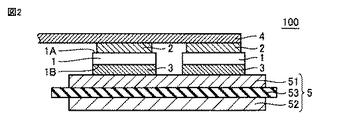
図1および図2を参照して、半導体装置100について説明する。半導体装置100は、複数の半導体素子1、複数の第1焼結金属層2、複数の第2焼結金属層3、リードフレーム4、および回路付絶縁基板5(回路基板)を主に備える。
次に、図1〜図4を参照して、実施の形態1に係る半導体装置の製造方法について説明する。
実施の形態1に係る半導体装置の製造方法は、複数の半導体素子1、緩衝部材、および回路付絶縁基板5を準備する工程(S10)と、粒径が100nm以下である焼結性金属粒子と、第1有機高分子とを含む、第1接合部材22および第2接合部材23を準備する工程(S20)と、リードフレーム4、第1接合部材22、半導体素子、第2接合部材23および回路付絶縁基板5が順に積層された積層体を準備する工程(S30)と、リードフレーム4と回路付絶縁基板5との間に第1圧力を印加する工程(S40)と、焼結金属粒子を焼結させて第1焼結金属層2および第2焼結金属層3を形成する工程(S50)とを備える。工程(S30)では、半導体素子の第1電極とリードフレーム4との間に第1接合部材22が、半導体素子の第2電極と回路付絶縁基板5との間に第2接合部材23が配置される。工程(S50)では、第1接合部材22および第2接合部材23は、焼結温度以上の第2温度に加熱されかつ第1圧力越えの第2圧力が印加される。第2圧力は、リードフレーム4と回路付絶縁基板5との間に印加される。
<半導体装置の構成>
次に、図5および図6を参照して、実施の形態2に係る半導体装置101について説明する。実施の形態2に係る半導体装置101は、実施の形態1に係る半導体装置100と基本的に同様の構成を備えるが、緩衝部材としてリードフレームに代えて複数の板状部材6を備え、さらに配線部材としてリードフレームに代えて複数のワイヤ7を備える点で異なる。複数の板状部材6の各々は、リードフレーム4(図1および図2参照)と基本的に同様の構成を備えるが、1つの第1焼結金属層2を介して1つの半導体素子1の第1電極のみと電気的に接続されている点で異なる。
次に、図7を参照して、実施の形態2に係る半導体装置101の製造方法について説明する。実施の形態2に係る半導体装置101の製造方法は、実施の形態1に係る半導体装置100の製造方法と基本的に同様の構成を備えるが、リードフレーム4に代えて複数の板状部材6が準備される点、および第1焼結金属層2および第2焼結金属層3を形成する工程(S50)の後に、工程(S50)により得られた接合体の板状部材6に配線部材としてのワイヤ7をボンディングする工程(S60)をさらに備えている点で異なる。
実施の形態2に係る半導体装置101の製造方法は、実施の形態1に係る半導体装置100の製造方法と基本的に同様の構成を備えている。そのため、実施の形態1に係る半導体装置100の製造方法と同様の効果を奏することができる。
<半導体装置の構成>
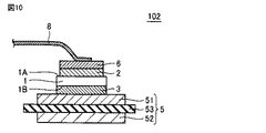
次に、図9および図10を参照して、実施の形態3に係る半導体装置102について説明する。実施の形態3に係る半導体装置102は、実施の形態1に係る半導体装置100と基本的に同様の構成を備えるが、緩衝部材としてリードフレームに代えて複数の板状部材6を備え、さらに配線部材としてリードフレームに代えて複数のリボン8を備える点で異なる。つまり、実施の形態3に係る半導体装置102は、実施の形態2に係る半導体装置101と基本的に同様の構成を備えるが、配線部材としてワイヤ7に代えてリボン8を備える点で異なる。
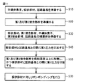
次に、図11を参照して、実施の形態3に係る半導体装置102の製造方法について説明する。実施の形態3に係る半導体装置102の製造方法は、実施の形態1に係る半導体装置100の製造方法と基本的に同様の構成を備えるが、リードフレーム4に代えて複数の板状部材6が準備される点、および第1焼結金属層2および第2焼結金属層3を形成する工程(S50)の後に、工程(S50)により得られた接合体の板状部材6にリボンボンディングを行う工程(S70)をさらに備えている点で異なる。つまり、実施の形態3に係る半導体装置102の製造方法は、実施の形態2に係る半導体装置101の製造方法と基本的に同様の構成を備えるが、ワイヤボンディングを行う工程に代えてリボンボンディングを行う工程(S70)を備える点で異なる。
実施の形態3に係る半導体装置102の製造方法は、実施の形態1に係る半導体装置の製造方法と基本的に同様の構成を備えている。そのため、実施の形態1に係る半導体装置100の製造方法と同様の効果を奏することができる。
<半導体モジュールの構成>
次に、図12を参照して、実施の形態4に係る半導体モジュール200について説明する。半導体モジュール200は、半導体装置100,101,102の少なくともいずれかを備える。図12は、半導体装置101を備える半導体モジュール200の断面図である。
半導体モジュール200は、上述した半導体装置101を備えているため、信頼性が高い。同様に、半導体モジュール200は、上述した半導体装置100または半導体装置102を備えている場合であっても、信頼性が高い。
Claims (8)
- 半導体素子、緩衝部材、および回路基板を準備する工程を備え、
前記半導体素子は、第1面および前記第1面の反対側に位置する第2面を有し、前記第1面上に形成されている少なくとも1つの第1電極および前記第2面上に形成されている第2電極とを含み、
第1有機高分子と粒径が100nm以下である焼結性金属粒子を含む第1接合部材および第2接合部材を準備する工程と、
前記半導体素子の前記第1電極と前記緩衝部材との間に前記第1接合部材を配置し、前記半導体素子の前記第2電極と前記回路基板との間に前記第2接合部材とを配置して、前記緩衝部材、前記第1接合部材、前記半導体素子、前記第2接合部材および前記回路基板が順に積層された積層体を準備する工程と、
前記第1接合部材および前記第2接合部材が前記焼結性金属粒子の焼結温度未満の第1温度にある前記積層体の前記緩衝部材と前記回路基板との間に第1圧力を印加する工程と、
前記第1圧力を印加する工程の後に、前記第1接合部材および前記第2接合部材が前記焼結性金属粒子の焼結温度以上の第2温度にある前記積層体の前記緩衝部材と前記回路基板との間に前記第1圧力越えの第2圧力を印加して、前記第1接合部材から第1焼結金属層を形成し、かつ前記第2接合部材から第2焼結金属層を形成する工程とをさらに備え、
前記第1温度は、120℃以上160℃以下であり、
前記第1圧力は、4MPa以上5MPa以下であり、
前記第1圧力を印加する工程での前記積層体に対する前記第1圧力の印加および前記第1温度への加温は、前記緩衝部材の前記第1接合部材と接触している面とは反対側に位置する面に接触される第1加圧部材、および前記回路基板の前記第2接合部材と接触している面とは反対側に位置する面に接触される第2加圧部材により実施され、
前記第1圧力を印加する工程において、前記第1加圧部材の温度は、前記第2加圧部材の温度よりも高い、半導体装置の製造方法。 - 前記第1接合部材および前記第2接合部材を準備する工程では、
前記第1有機高分子よりも分子量の小さい第2有機高分子により被覆された前記焼結性金属粒子を含む第3接合部材および第4接合部材を準備する工程と、
前記第3接合部材および前記第4接合部材を前記焼結温度未満の第3温度に加熱して前記第2有機高分子の少なくとも一部を前記第1有機高分子に変換する工程とを含む、請求項1に記載の半導体装置の製造方法。 - 前記第2温度は245℃以上275℃以下であり、前記第2圧力は20MPa以上30MPa以下の圧力である、請求項1または2に記載の半導体装置の製造方法。
- 前記第1焼結金属層および前記第2焼結金属層を形成する工程では、前記第1焼結金属層および前記第2焼結金属層の各厚みが30μm以上50μm以下とされる、請求項1〜3のいずれか1項に記載の半導体装置の製造方法。
- 前記緩衝部材はリードフレームを有する、請求項1〜4のいずれか1項に記載の半導体装置の製造方法。
- 前記緩衝部材は板状部材を有し、
前記第1焼結金属層および前記第2焼結金属層を形成する工程の後に、前記板状部材に配線部材をボンディングする工程をさらに備える、請求項1〜4のいずれか1項に記載の半導体装置の製造方法。 - 前記第1焼結金属層および前記第2焼結金属層を形成する工程での前記積層体に対する前記第2圧力の印加および前記第2温度への加温は、前記第1加圧部材および前記第2加圧部材により実施され、
前記第1焼結金属層および前記第2焼結金属層を形成する工程において、前記第1加圧部材の温度は、前記第2加圧部材の温度よりも高い、請求項1〜6のいずれか1項に記載の半導体装置の製造方法。 - 前記第1焼結金属層および前記第2焼結金属層を形成する工程は、圧力が印加されていない前記積層体における前記第1接合部材および前記第2接合部材を前記第2温度にまで加熱する工程と、前記第1接合部材および前記第2接合部材が前記第2温度にある前記積層体における前記緩衝部材と前記回路基板との間に前記第2圧力が印加される工程とを含む、請求項1〜7のいずれか1項に記載の半導体装置の製造方法。
Priority Applications (1)
| Application Number | Priority Date | Filing Date | Title |
|---|---|---|---|
| JP2016256337A JP6643975B2 (ja) | 2016-12-28 | 2016-12-28 | 半導体装置の製造方法 |
Applications Claiming Priority (1)
| Application Number | Priority Date | Filing Date | Title |
|---|---|---|---|
| JP2016256337A JP6643975B2 (ja) | 2016-12-28 | 2016-12-28 | 半導体装置の製造方法 |
Publications (3)
| Publication Number | Publication Date |
|---|---|
| JP2018110149A JP2018110149A (ja) | 2018-07-12 |
| JP2018110149A5 JP2018110149A5 (ja) | 2018-12-27 |
| JP6643975B2 true JP6643975B2 (ja) | 2020-02-12 |
Family
ID=62844633
Family Applications (1)
| Application Number | Title | Priority Date | Filing Date |
|---|---|---|---|
| JP2016256337A Active JP6643975B2 (ja) | 2016-12-28 | 2016-12-28 | 半導体装置の製造方法 |
Country Status (1)
| Country | Link |
|---|---|
| JP (1) | JP6643975B2 (ja) |
Families Citing this family (6)
| Publication number | Priority date | Publication date | Assignee | Title |
|---|---|---|---|---|
| JP7238985B2 (ja) * | 2019-06-20 | 2023-03-14 | 富士電機株式会社 | 半導体装置及び半導体装置の製造方法 |
| JP7484097B2 (ja) * | 2019-07-18 | 2024-05-16 | 株式会社レゾナック | 半導体装置 |
| JP7247053B2 (ja) * | 2019-08-02 | 2023-03-28 | 株式会社東芝 | 半導体装置 |
| JP7404208B2 (ja) * | 2020-09-24 | 2023-12-25 | 株式会社東芝 | 半導体装置 |
| DE112021004922T5 (de) * | 2020-11-27 | 2023-07-13 | Rohm Co., Ltd. | Halbleiterbauelement |
| WO2023190573A1 (ja) | 2022-03-30 | 2023-10-05 | 三井金属鉱業株式会社 | 接合体の製造方法及び被接合体の接合方法 |
Family Cites Families (3)
| Publication number | Priority date | Publication date | Assignee | Title |
|---|---|---|---|---|
| JP5542567B2 (ja) * | 2010-07-27 | 2014-07-09 | 三菱電機株式会社 | 半導体装置 |
| JP2014029897A (ja) * | 2012-07-31 | 2014-02-13 | Hitachi Ltd | 導電性接合体およびそれを用いた半導体装置 |
| JP6147176B2 (ja) * | 2013-12-02 | 2017-06-14 | 三菱電機株式会社 | 半導体素子の基板への接合方法 |
-
2016
- 2016-12-28 JP JP2016256337A patent/JP6643975B2/ja active Active
Also Published As
| Publication number | Publication date |
|---|---|
| JP2018110149A (ja) | 2018-07-12 |
Similar Documents
| Publication | Publication Date | Title |
|---|---|---|
| JP6643975B2 (ja) | 半導体装置の製造方法 | |
| JP6171622B2 (ja) | パワーモジュール用基板、パワーモジュール及びパワーモジュール用基板を製造する方法 | |
| JP5193452B2 (ja) | パワー半導体素子とハウジングとを備えた装置の製造方法 | |
| US12057375B2 (en) | Semiconductor device and method for manufacturing semiconductor device | |
| JP3846699B2 (ja) | 半導体パワーモジュールおよびその製造方法 | |
| JP6366766B2 (ja) | 半導体装置 | |
| US10490491B2 (en) | Semiconductor device | |
| JP6143687B2 (ja) | 半導体装置および半導体装置の製造方法 | |
| CN109216234B (zh) | 用于处理半导体衬底的设备和方法 | |
| US11935811B2 (en) | Baseplate for a semiconductor module and method for producing a baseplate | |
| JPWO2015137109A1 (ja) | 半導体装置の製造方法および半導体装置 | |
| JP5954374B2 (ja) | 絶縁基板、その製造方法、半導体モジュールおよび半導体装置 | |
| US9768036B2 (en) | Power semiconductor substrates with metal contact layer and method of manufacture thereof | |
| JP6881304B2 (ja) | 半導体装置及び半導体装置の製造方法 | |
| JP6019790B2 (ja) | 接合方法及び接合部材 | |
| JP7351134B2 (ja) | 半導体装置及び半導体装置の製造方法 | |
| JP2007150342A (ja) | 半導体装置およびその製造方法 | |
| JP2014143342A (ja) | 半導体モジュール及びその製造方法 | |
| JP5630375B2 (ja) | 絶縁基板、その製造方法、半導体モジュールおよび半導体装置 | |
| WO2013021983A1 (ja) | 半導体装置及びその製造方法 | |
| JP2006013420A (ja) | 電子部品収納用パッケージおよび電子装置 | |
| JP2014030059A (ja) | 絶縁基板、その製造方法、半導体モジュールおよび半導体装置 | |
| JP2014053406A (ja) | 半導体装置およびその製造方法 | |
| TWI745572B (zh) | 電子零件安裝模組 | |
| TWI733011B (zh) | 電子零件安裝模組之製造方法 |
Legal Events
| Date | Code | Title | Description |
|---|---|---|---|
| A521 | Request for written amendment filed |
Free format text: JAPANESE INTERMEDIATE CODE: A523 Effective date: 20181107 |
|
| A621 | Written request for application examination |
Free format text: JAPANESE INTERMEDIATE CODE: A621 Effective date: 20181107 |
|
| A977 | Report on retrieval |
Free format text: JAPANESE INTERMEDIATE CODE: A971007 Effective date: 20190802 |
|
| A131 | Notification of reasons for refusal |
Free format text: JAPANESE INTERMEDIATE CODE: A131 Effective date: 20190806 |
|
| A521 | Request for written amendment filed |
Free format text: JAPANESE INTERMEDIATE CODE: A523 Effective date: 20191003 |
|
| TRDD | Decision of grant or rejection written | ||
| A01 | Written decision to grant a patent or to grant a registration (utility model) |
Free format text: JAPANESE INTERMEDIATE CODE: A01 Effective date: 20191210 |
|
| A61 | First payment of annual fees (during grant procedure) |
Free format text: JAPANESE INTERMEDIATE CODE: A61 Effective date: 20200107 |
|
| R150 | Certificate of patent or registration of utility model |
Ref document number: 6643975 Country of ref document: JP Free format text: JAPANESE INTERMEDIATE CODE: R150 |
|
| R250 | Receipt of annual fees |
Free format text: JAPANESE INTERMEDIATE CODE: R250 |
|
| R250 | Receipt of annual fees |
Free format text: JAPANESE INTERMEDIATE CODE: R250 |


