JP6163341B2 - Break device - Google Patents
Break device Download PDFInfo
- Publication number
- JP6163341B2 JP6163341B2 JP2013076715A JP2013076715A JP6163341B2 JP 6163341 B2 JP6163341 B2 JP 6163341B2 JP 2013076715 A JP2013076715 A JP 2013076715A JP 2013076715 A JP2013076715 A JP 2013076715A JP 6163341 B2 JP6163341 B2 JP 6163341B2
- Authority
- JP
- Japan
- Prior art keywords
- substrate
- break
- unit
- bonded substrate
- bonded
- Prior art date
- Legal status (The legal status is an assumption and is not a legal conclusion. Google has not performed a legal analysis and makes no representation as to the accuracy of the status listed.)
- Expired - Fee Related
Links
Images


Classifications
-
- Y—GENERAL TAGGING OF NEW TECHNOLOGICAL DEVELOPMENTS; GENERAL TAGGING OF CROSS-SECTIONAL TECHNOLOGIES SPANNING OVER SEVERAL SECTIONS OF THE IPC; TECHNICAL SUBJECTS COVERED BY FORMER USPC CROSS-REFERENCE ART COLLECTIONS [XRACs] AND DIGESTS
- Y02—TECHNOLOGIES OR APPLICATIONS FOR MITIGATION OR ADAPTATION AGAINST CLIMATE CHANGE
- Y02P—CLIMATE CHANGE MITIGATION TECHNOLOGIES IN THE PRODUCTION OR PROCESSING OF GOODS
- Y02P40/00—Technologies relating to the processing of minerals
- Y02P40/50—Glass production, e.g. reusing waste heat during processing or shaping
- Y02P40/57—Improving the yield, e-g- reduction of reject rates
Description
本発明は、ブレイク装置に関するものである。 The present invention relates to a break device.
液晶装置は、液晶層を間に介在するように第1基板と第2基板とがシール材によって貼り合わされる貼り合わせ基板によって構成される(例えば特許文献1)。この貼り合わせ基板は、生産性の観点から、まず大判の状態で作製され、これを分断して複数の貼り合わせ基板とする。この分断方法について詳細に説明すると、まず貼り合わせ基板の第1基板側の面にスクライブラインを形成し、次に、第2基板側から貼り合わせ基板を押圧して撓ませ、第1基板をスクライブラインに沿ってブレイクする。続いて、貼り合わせ基板の第2基板側の面にスクライブラインを形成し、次に、第1基板側から貼り合わせ基板を押圧して撓ませ、第2基板をスクライブラインに沿ってブレイクする。 The liquid crystal device is configured by a bonded substrate in which a first substrate and a second substrate are bonded together with a sealing material so that a liquid crystal layer is interposed (for example, Patent Document 1). This bonded substrate is first manufactured in a large format from the viewpoint of productivity, and is divided into a plurality of bonded substrates. This cutting method will be described in detail. First, a scribe line is formed on the surface of the bonded substrate on the first substrate side, and then the bonded substrate is pressed and bent from the second substrate side to scribe the first substrate. Break along the line. Subsequently, a scribe line is formed on the surface of the bonded substrate on the second substrate side, and then the bonded substrate is pressed and bent from the first substrate side to break the second substrate along the scribe line.
上述した方法では、第1基板をブレイクした後に、貼り合わせ基板の表裏を反転させて第2基板をブレイクする必要がある。このように貼り合わせ基板の表裏を反転させることは生産性が低下するといった問題が生じるため、貼り合わせ基板の表裏を反転させることなく第1基板及び第2基板をブレイクすることが望ましい。 In the method described above, after breaking the first substrate, it is necessary to break the second substrate by inverting the front and back of the bonded substrate. Thus, since reversing the front and back of the bonded substrate causes a problem that productivity is lowered, it is desirable to break the first substrate and the second substrate without reversing the front and back of the bonded substrate.
本発明の課題は、貼り合わせ基板の表裏を反転させることなく第1基板及び第2基板をブレイクすることができるブレイク装置を提供することにある。 The subject of this invention is providing the breaking apparatus which can break a 1st board | substrate and a 2nd board | substrate, without reversing the front and back of a bonding board | substrate.
(1)本発明のある側面に係るブレイク装置は、第1基板と第2基板とが貼り合わされた貼り合わせ基板の両面に形成されたスクライブラインに沿って貼り合わせ基板をブレイクする装置である。このブレイク装置は、搬送ユニット、第1ブレイクユニット、及び第2ブレイクユニットを備える。搬送ユニットは、貼り合わせ基板を上流から下流に搬送する。第1ブレイクユニットは、第1基板側の面に形成されたスクライブラインに沿って第1基板をブレイクする。第2ブレイクユニットは、第1ブレイクユニットの下流に配置される。また、第2ブレイクユニットは、第2基板側の面に形成されたスクライブラインに沿って第2基板をブレイクする。 (1) A breaking device according to an aspect of the present invention is a device that breaks a bonded substrate along a scribe line formed on both surfaces of a bonded substrate on which a first substrate and a second substrate are bonded. The break device includes a transport unit, a first break unit, and a second break unit. The transport unit transports the bonded substrate from upstream to downstream. The first break unit breaks the first substrate along a scribe line formed on the surface on the first substrate side. The second break unit is disposed downstream of the first break unit. The second break unit breaks the second substrate along a scribe line formed on the surface on the second substrate side.
この構成によれば、搬送ユニットによって搬送される貼り合わせ基板は、まず第1ブレイクユニットによって第1基板がブレイクされ、次に、第2ブレイクユニットによって第2基板がブレイクされる。このように、搬送方向に並べて配置された第1ブレイクユニット及び第2ブレイクユニットによって、貼り合わせ基板の表裏を反転させることなく第1基板と第2基板との両方をブレイクすることができる。この結果、生産性を向上させることができる。 According to this configuration, the first substrate is first broken by the first break unit, and then the second substrate is broken by the second break unit. In this way, both the first substrate and the second substrate can be broken without inverting the front and back of the bonded substrate board by the first break unit and the second break unit arranged side by side in the transport direction. As a result, productivity can be improved.
(2)好ましくは、第1ブレイクユニットと第2ブレイクユニットとは、互いに同期してブレイク動作を実行する。この構成によれば、例えば、搬送ユニットによって搬送される貼り合わせ基板が、搬送方向に所定間隔をあけて複数のスクライブラインが形成されている場合、第1ブレイクユニットにおいて、上流側のスクライブラインに沿って第1基板をブレイクするとともに、第2ブレイクユニットにおいて、下流側のスクライブラインに沿って第2基板をブレイクすることができる。このように、貼り合わせ基板には対向する方向に2つの押圧力が作用するため、貼り合わせ基板が押圧力によって歪んでしまうことを抑制することができる。 (2) Preferably, the first break unit and the second break unit perform a break operation in synchronization with each other. According to this configuration, for example, when the bonded substrate transported by the transport unit has a plurality of scribe lines formed at predetermined intervals in the transport direction, in the first break unit, on the upstream scribe line. The first substrate can be broken along the second substrate, and the second substrate can be broken along the scribe line on the downstream side in the second break unit. In this way, since two pressing forces act on the bonded substrate in opposite directions, the bonded substrate can be prevented from being distorted by the pressing force.
(3)好ましくは、第1ブレイクユニット及び第2ブレイクユニットの少なくとも一方は、ブレイクバーとバックアップバーとを有する。ブレイクバーは、搬送ユニットの搬送面と平行に延びる押圧部を有する。この押圧部は、貼り合わせ基板をブレイクする際に貼り合わせ基板と接触する部分である。バックアップバーは、押圧部の幅よりも広い間隔をあけて押圧部の長手方向に沿って延びる2つの支持部を有する。各支持部は、貼り合わせ基板をブレイクする際に貼り合わせ基板と接触する部分である。押圧部は、貼り合わせ基板の搬送路を介して、各支持部間と対向するように配置される。押圧部及び各支持部の少なくとも一方が押圧部及び各支持部の他方側に向かって移動することによって、貼り合わせ基板がブレイクされる。 (3) Preferably, at least one of the first break unit and the second break unit has a break bar and a backup bar. The break bar has a pressing portion extending in parallel with the transport surface of the transport unit. The pressing portion is a portion that comes into contact with the bonded substrate when the bonded substrate is broken. The backup bar has two support portions that extend along the longitudinal direction of the pressing portion with an interval wider than the width of the pressing portion. Each support portion is a portion that comes into contact with the bonded substrate when the bonded substrate is broken. The pressing portion is disposed so as to face between the support portions via the conveyance path of the bonded substrate. The bonded substrate is broken by moving at least one of the pressing part and each supporting part toward the other side of the pressing part and each supporting part.
この構成によれば、ブレイクユニットは、貼り合わせ基板の一方面側から2つの支持部によって支持し、貼り合わせ基板の他方面側から押圧部で貼り合わせ基板を押圧することによって、貼り合わせ基板をブレイクする。このように、貼り合わせ基板はいわゆる3点曲げとなるため、より確実に貼り合わせ基板をブレイクすることができる。なお、押圧部及び各支持部は、ブレイク動作時以外にも貼り合わせ基板と接触していてもよい。 According to this configuration, the break unit is supported by the two support portions from one side of the bonded substrate, and the bonded substrate is pressed by pressing the bonded substrate with the pressing portion from the other surface of the bonded substrate. Break. Thus, since the bonded substrate is a so-called three-point bending, the bonded substrate can be more reliably broken. In addition, the pressing part and each supporting part may be in contact with the bonded substrate substrate other than during the break operation.
(4)好ましくは、バックアップバーは、各支持部が互いに離れるように変形可能である。この構成によれば、貼り合わせ基板をブレイクするために押圧部が貼り合わせ基板を押圧すると、各支持部が互いに離れる。これにより、貼り合わせ基板には、スクライブラインから離れる方向に引張り力が作用するため、より小さな押圧力で貼り合わせ基板をブレイクすることができる。 (4) Preferably, the backup bar is deformable so that the support portions are separated from each other. According to this configuration, when the pressing portion presses the bonded substrate to break the bonded substrate, the support portions are separated from each other. Thereby, since a tensile force acts on the bonded substrate in a direction away from the scribe line, the bonded substrate can be broken with a smaller pressing force.
(5)好ましくは、各支持部は、各支持部が離れる方向の側面において、支持部の長手方向に沿って延びる凹部が形成されている。この構成によれば、上述したように、押圧部が貼り合わせ基板を押圧すると、各支持部が互いに離れる方向に変形することができる。 (5) Preferably, each support part is formed with a recess extending along the longitudinal direction of the support part on the side surface in the direction in which each support part is separated. According to this configuration, as described above, when the pressing portion presses the bonded substrate, the respective supporting portions can be deformed in directions away from each other.
(6)好ましくは、第1ブレイクユニット及び第2ブレイクユニットの少なくとも一方は、上流及び下流に移動可能である。この構成によれば、複数のスクライブラインが形成されている貼り合わせ基板において、スクライブラインの種々のピッチに対応することができる。 (6) Preferably, at least one of the first break unit and the second break unit is movable upstream and downstream. According to this configuration, it is possible to cope with various pitches of the scribe lines in the bonded substrate in which a plurality of scribe lines are formed.
(7)好ましくは、前記搬送ユニットは、上流及び下流に移動可能である。
(7) Preferably, the transport unit is movable upstream and downstream.
本発明によれば、貼り合わせ基板の表裏を反転させることなく第1基板及び第2基板をブレイクすることができる。 According to the present invention, it is possible to break the first substrate and the second substrate without inverting the front and back of the bonded substrate.
以下、本発明に係るブレイク装置の実施形態について図面を参照しつつ説明する。図1は、ブレイク装置の全体を示す斜視図である。なお、図1の左側を上流、右側を下流とする。また、以下の説明において「搬送方向」とは、下流に向かう方向を意味する。 Hereinafter, embodiments of a break device according to the present invention will be described with reference to the drawings. FIG. 1 is a perspective view showing the entire breaking device. The left side of FIG. 1 is the upstream side and the right side is the downstream side. In the following description, “conveying direction” means a direction toward the downstream.
図1に示すように、ブレイク装置1は、貼り合わせ基板10の両面に形成されたスクライブライン13に沿って貼り合わせ基板をブレイクするための装置であり、上流から順に、第1搬送ユニット2、第1ブレイクユニット3、支持テーブル4、第2ブレイクユニット5、及び第2搬送ユニット6を備えている。なお、これら各ユニット2〜6は、各ユニット間の間隔を変えることができるよう、上流側又は下流側に移動可能である。
As shown in FIG. 1, the
ブレイク装置1の加工対象である貼り合わせ基板10は、上側基板(第2基板の一例)11と下側基板(第1基板の一例)12とが貼り合わされて構成される基板であって、上側基板11と下側基板12との間で例えば液晶層を構成する。また、貼り合わせ基板10は、図示しない複数のシール部材が上側基板11と下側基板12との間に配置されており、このシール部材によって液晶層を囲んでいる。このシール部材は、ブレイク後の貼り合わせ基板の数だけ配置されている。
A
本実施形態における貼り合わせ基板10は、上側基板11が上側、下側基板12が下側に配置された状態で搬送される。貼り合わせ基板10は、上面(上側基板11側の面)に複数のスクライブライン13が所定のピッチで形成されている。また、貼り合わせ基板10は、下面(下側基板12側の面)にも複数のスクライブライン13が形成されている。この下面に形成されたスクライブライン13は、上面に形成されたスクライブライン13と対応する位置に形成されている。なお、本実施形態では、搬送方向と直交する方向にのみスクライブライン13が形成されているが、スクライブライン13は、搬送方向と平行する方向に形成されていてもよい。
The
第1搬送ユニット2は、搬送面21上に載置された貼り合わせ基板10を、下流に向かって搬送するための装置であり、例えばベルトコンベアなどによって構成することができる。具体的には、第1搬送ユニット2は、一対のローラ22a、22bと、各ローラ22a、22bに巻き掛けられたベルト23と、を有する。図示しない駆動モータが各ローラ22a、22bを時計回りに回転駆動することによって、上側に位置するベルト23が貼り合わせ基板10を下流に搬送する。
The 1st conveyance unit 2 is an apparatus for conveying the bonding board |
第1搬送ユニット2の下流側に設置された第1ブレイクユニット3は、ブレイクバー31と、バックアップバー32とを備えている。ブレイクバー31とバックアップバー32とは、上下方向において対向する位置に配置されている。より詳細には、ブレイクバー31とバックアップバー32とは、貼り合わせ基板10の搬送路を介して対向する位置に配置されており、ブレイクバー31は搬送路の上方に配置され、バックアップバー32は搬送路の下方に配置されている。
The first break unit 3 installed on the downstream side of the first transport unit 2 includes a
ブレイクバー31は、第1搬送ユニット2の搬送面21と平行且つ搬送方向と直交する方向に延びている。ブレイクバー31の下部は、搬送面21と平行且つ搬送方向と直交する方向に延びる三角柱状に形成されており、先端(下端)に行くほど細くなる先細り形状となっている。このブレイクバー31の先端における稜線部が、ブレイク動作時に貼り合わせ基板10と接触する押圧部311である。ブレイクバー31は、作動位置と非作動位置との間で昇降可能に設置されており、作動位置では押圧部311が貼り合わせ基板10を押圧する。また、ブレイクバー31が作動位置から上昇して非作動位置にあるときは、押圧部311は貼り合わせ基板10と接触しない。
The
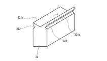
バックアップバー32は、ブレイクバー31の長手方向に沿って延びている、すなわち第1搬送ユニット2の搬送面21と平行且つ搬送方向と直交する方向に延びている。バックアップバー32は2つの上部を有しており、各上部は搬送面21と平行且つ搬送方向と直交する方向に延びる三角柱状に形成されている。また、バックアップバー32の各上部は、先端(上端)に行くほど細くなる先細り形状となっている。このバックアップバー32の各先端における2つの稜線部が、貼り合わせ基板10と接触する支持部321a、321bである。この各支持部321a、321bは、押圧部311の長手方向に沿って延びている。各支持部321a、321bは互いに所定間隔をあけて延びている。そして、押圧部311は、貼り合わせ基板10の搬送路を介して各支持部321a、321b間と対向する位置に配置されている。なお、各支持部321a、321b間の距離は、押圧部311の幅よりも広い。
The
支持テーブル4は、第1ブレイクユニット3と第2ブレイクユニット5との間において、貼り合わせ基板10を支持するためのテーブルである。この支持テーブル4の上面である支持面41は、第1搬送ユニット2の搬送面21、及び第2搬送ユニット6の搬送面61と同じ高さに位置する。
The support table 4 is a table for supporting the bonded
第2ブレイクユニット5は、ブレイクバー51と、バックアップバー52とを備えている。ブレイクバー51は先端(上端)に押圧部511を有しており、バックアップバー52は先端(下端)に2つの支持部521a、521bを有している。第2ブレイクユニット5は、ブレイクバー51が下方に位置しバックアップバー52が上方に位置するという配置以外は上述した第1ブレイクユニット3と同様の構成であるため、詳細な説明を省略する。
The second break unit 5 includes a
第2搬送ユニット6は、搬送面61に載置された貼り合わせ基板10を下流に向かって搬送する。この第2搬送ユニット6は、一対のローラ62a、62bと、各ローラ62a、62bに巻き掛けられたベルト63と、を有する。第2搬送ユニット6は、上述した第1搬送ユニット2と同様の構成であるため、その詳細な説明を省略する。
The
次に上述したように構成されたブレイク装置1の動作について説明する。
Next, the operation of the
図1に示すように、まず、貼り合わせ基板10のサイズ、及び各スクライブライン13のピッチに基づいて、各ユニット2〜6の位置を調整する。具体的には、第1ブレイクユニット3のブレイクバー31の押圧部311と、第2ブレイクユニット5のブレイクバー51の押圧部511との搬送方向における距離を、スクライブライン13のピッチと同じにする。その他、第1及び第2搬送ユニット2,6と支持テーブル4とを、貼り合わせ基板10がスムーズに搬送方向に搬送されるように、適切な位置にセットする。
As shown in FIG. 1, first, the positions of the units 2 to 6 are adjusted based on the size of the bonded
次に、図示しないスクライブ装置によって両面にスクライブライン13が形成された貼り合わせ基板10が、第1搬送ユニット2の搬送面21上に載置される。第1搬送ユニット2は、この貼り合わせ基板10を間欠的に搬送する。具体的には、第1搬送ユニット2は、貼り合わせ基板10を下流側に搬送し、図2に示すように貼り合わせ基板10の下流側のスクライブライン13が第1ブレイクユニット3に到達すると、その搬送を停止する。より詳細には、貼り合わせ基板10の下流側のスクライブライン13が第1ブレイクユニット3におけるブレイクバー31の押圧部311の下方に位置すると、第1搬送ユニット2は搬送を停止する。なお、貼り合わせ基板10が搬送されている間、第1及び第2ブレイクユニット3、5のブレイクバー31、51は、非作動位置にある。
Next, the bonded
この状態において、第1ブレイクユニット3が作動する。具体的には、第1ブレイクユニット3のブレイクバー31が作動位置まで下降し、押圧部311が貼り合わせ基板10を上側基板11側から下流側のスクライブライン13に沿って押圧する。これによって、貼り合わせ基板10の下側基板12が下流側のスクライブライン13に沿ってブレイクされる。なお、このブレイク動作の際、貼り合わせ基板10は、バックアップバー32の各支持部321a、321bによって、下側から支持されている。
In this state, the first break unit 3 operates. Specifically, the
貼り合わせ基板10の下側基板12が下流側のスクライブライン13に沿ってブレイクされると、第1ブレイクユニット3のブレイクバー31は非作動位置に戻るとともに第1搬送ユニット2が作動し、貼り合わせ基板10はさらに下流側に搬送される。そして、図3に示すように、貼り合わせ基板10の下流側のスクライブライン13が第2ブレイクユニット5に到達すると、第1搬送ユニット2は貼り合わせ基板10の搬送を停止する。より詳細には、貼り合わせ基板10の下流側のスクライブライン13が第2ブレイクユニット5におけるブレイクバー51の押圧部511の上方に位置すると、第1搬送ユニット2は搬送動作を停止する。なお、この状態において、貼り合わせ基板10の上流側のスクライブライン13は、第1ブレイクユニット3に到達している。そして、貼り合わせ基板10の上流側のスクライブライン13は、第1ブレイクユニット3におけるブレイクバー31の押圧部311の下方に位置する。
When the
この状態において、第1ブレイクユニット3及び第2ブレイクユニット5が同期して作動する。具体的には、第2ブレイクユニット5のブレイクバー51が作動位置まで上昇し、押圧部511が貼り合わせ基板10を下側基板12側から下流側のスクライブライン13に沿って押圧する。これによって、貼り合わせ基板10の上側基板11が下流側のスクライブライン13に沿ってブレイクされる。なお、このブレイク動作の際、貼り合わせ基板10は、バックアップバー52の各支持部521a、521bによって、上側から支持されている。
In this state, the first break unit 3 and the second break unit 5 operate in synchronization. Specifically, the
また、第2ブレイクユニット5による上側基板11のブレイクと同時に、第1ブレイクユニットユニット3による下側基板12のブレイクが行われる。すなわち、第1ブレイクユニット3のブレイクバー31が作動位置まで下降し、押圧部311が貼り合わせ基板10を上側基板11側から上流側のスクライブライン13に沿って押圧する。これによって、貼り合わせ基板10の下側基板12が上流側のスクライブライン13に沿ってブレイクされる。このように、上側基板11が下流側のスクライブライン13に沿ってブレイクされるとともに、下側基板12が上流側のスクライブライン13に沿ってブレイクされる。なお、貼り合わせ基板10の最下流側の部分10aは、上側基板11及び下側基板12ともにブレイクされたため、図4に示すように、残りの貼り合わせ基板10bから完全に分断された状態となる。
Further, simultaneously with the break of the
続いて、第1及び第2ブレイクユニット3、5のブレイクバー31、51が非作動位置に戻るとともに第1及び第2搬送ユニット2、6が作動し、貼り合わせ基板10がさらに下流側に搬送される。そして、図4に示すように、貼り合わせ基板10の上流側のスクライブライン13が第2ブレイクユニット5に到達すると、第1及び第2搬送ユニット2,6は貼り合わせ基板10の搬送を停止する。より詳細には、貼り合わせ基板10の上流側のスクライブライン13が第2ブレイクユニット5におけるブレイクバー51の押圧部511の上方に位置すると、第1及び第2搬送ユニット2、6は搬送動作を停止する。
Subsequently, the break bars 31 and 51 of the first and second break units 3 and 5 return to the non-operating position, and the first and
そして、第2ブレイクユニット5が作動する。具体的には、第2ブレイクユニット5のブレイクバー51が作動位置まで上昇し、押圧部511が貼り合わせ基板10を下側基板12側から上流側のスクライブライン13に沿って押圧する。これによって、貼り合わせ基板10の上側基板11が上流側のスクライブライン13に沿ってブレイクされる。
Then, the second break unit 5 operates. Specifically, the
[特徴]
本実施形態に係るブレイク装置は、次の特徴を有する。
[Feature]
The break device according to the present embodiment has the following features.
(1)第1及び第2搬送ユニット2,6によって搬送される貼り合わせ基板10は、まず第1ブレイクユニット3によって下側基板12がブレイクされ、次に、第2ブレイクユニット5によって上側基板11がブレイクされる。このように、搬送方向に並べて配置された第1ブレイクユニット3及び第2ブレイクユニット5によって、貼り合わせ基板10の表裏を反転させることなく上側基板11と下側基板12との両方をブレイクすることができる。この結果、生産性を向上させることができる。
(1) The bonded
(2)第1ブレイクユニット3と第2ブレイクユニット5とは、互いに同期してブレイク動作を実行する。このため、第1ブレイクユニット3によって、上流側のスクライブライン13に沿って下側基板12をブレイクするとともに、第2ブレイクユニット5によって、下流側のスクライブライン13に沿って上側基板11をブレイクすることができる。このように、貼り合わせ基板10には対向する方向に2つの押圧力が作用するため、この押圧力によって貼り合わせ基板10が歪んでしまうことを抑制することができる。
(2) The first break unit 3 and the second break unit 5 perform a break operation in synchronization with each other. Therefore, the first break unit 3 breaks the
(3)第1ブレイクユニット3は、貼り合わせ基板10の下面側から2つの支持部321a、321bによって支持し、貼り合わせ基板10の上面側から押圧部311で貼り合わせ基板10を押圧することによって、貼り合わせ基板10をブレイクする。このように、貼り合わせ基板はいわゆる3点曲げとなるため、より確実に貼り合わせ基板10をブレイクすることができる。
(3) The first break unit 3 is supported by the two
[変形例]
以上、本発明の実施形態について説明したが、本発明はこれらに限定されるものではなく、本発明の趣旨を逸脱しない限りにおいて種々の変更が可能である。
[Modification]
As mentioned above, although embodiment of this invention was described, this invention is not limited to these, A various change is possible unless it deviates from the meaning of this invention.
変形例1
上記実施形態では、第1ブレイクユニット3によって貼り合わせ基板10の下側基板12をブレイクし、第2ブレイクユニット5によって上側基板11をブレイクするが、特にこれに限定されない。例えば、第1ブレイクユニット3によって上側基板11をブレイクし、第2ブレイクユニット5によって下側基板12をブレイクするような構成としてもよい。この場合、第1ブレイクユニット3のブレイクバー31とバックアップバー32との位置を上下方向に反転させるとともに、第2ブレイクユニット5のブレイクバー51とバックアップバー52との位置を上下方向に反転させる。
In the above embodiment, the
変形例2
上記実施形態では、ブレイクバー31,51が作動位置に下降又は上昇することによって貼り合わせ基板10をブレイクするが、特にこれに限定されない。例えば、第1ブレイクユニット3において、ブレイクバー31は下降せずに、バックアップバー32が上昇することによって下側基板12をブレイクしてもよい。また、第2ブレイクユニット5において、ブレイクバー51は上昇せずに、バックアップバー52が下降することによって上側基板11をブレイクしてもよい。さらには、ブレイクバー31、51及びバックアップバー32,52の双方が互いに近づくように昇降して、貼り合わせ基板10をブレイクしてもよい。
Modification 2
In the embodiment described above, the bonded
変形例3
第1ブレイクユニット3のバックアップバー32における支持部321a、321bは、互いに離れるように変形可能であってもよい。例えば、図5に示すように、各支持部321a、321bが離れる方向の側面に、凹部322が形成されている。この凹部322によって、各支持部321a、321bが互いに離れるようにバックアップバー32は変形可能である。
Modification 3
The
変形例4
上記実施形態では、第1及び第2ブレイクユニット3、5は、ブレイクバー31、51によって貼り合わせ基板10をブレイクするが、ブレイクバー31、51の代わりに、貼り合わせ基板10上を押圧しながら転がる押圧ローラによって貼り合わせ基板10をブレイクしてもよい。
Modification 4
In the above-described embodiment, the first and second break units 3 and 5 break the bonded
変形例5
上記実施形態では、バックアップバー32は1つの部材から形成されており、このバックアップバー32の先端が2股に分かれる構造とすることで2つの支持部321a、321bが形成されているが、特にこれに限定されない。例えば、バックアップバー32が2つの部材によって構成されており、各部材の先端を支持部321a、321bとすることもできる。
Modification 5
In the above embodiment, the
1 ブレイク装置
2 第1搬送ユニット
21 搬送面
3 第1ブレイクユニット
31 ブレイクバー
311 押圧部
32 バックアップバー
321a、321b 支持部
5 第2ブレイクユニット
51 ブレイクバー
511 押圧部
52 バックアップバー
521a、21b 支持部
6 第2搬送ユニット
61 搬送面
10 貼り合わせ基板
11 第2基板
12 第1基板
13 スクライブライン
DESCRIPTION OF
Claims (5)
前記貼り合わせ基板を上流から下流に搬送する搬送ユニットと、
前記第1基板側の面に形成された前記スクライブラインに沿って前記第1基板をブレイクする第1ブレイクユニットと、
前記第1ブレイクユニットの下流に配置され、前記第2基板側の面に形成された前記スクライブラインに沿って前記第2基板をブレイクする第2ブレイクユニットとを備え、
前記第1ブレイクユニットと前記第2ブレイクユニットとは、互いに同期してブレイク動作を実行する、ブレイク装置。 A breaking device for breaking a bonded substrate along a scribe line formed on both surfaces of a bonded substrate on which a first substrate and a second substrate are bonded,
A transport unit for transporting the bonded substrate from upstream to downstream;
A first break unit that breaks the first substrate along the scribe line formed on the surface of the first substrate;
A second break unit that is disposed downstream of the first break unit and breaks the second substrate along the scribe line formed on the second substrate side surface ;
The break device, wherein the first break unit and the second break unit execute a break operation in synchronization with each other .
前記貼り合わせ基板を上流から下流に搬送する搬送ユニットと、 A transport unit for transporting the bonded substrate from upstream to downstream;
前記第1基板側の面に形成された前記スクライブラインに沿って前記第1基板をブレイクする第1ブレイクユニットと、 A first break unit that breaks the first substrate along the scribe line formed on the surface of the first substrate;
前記第1ブレイクユニットの下流に配置され、前記第2基板側の面に形成された前記スクライブラインに沿って前記第2基板をブレイクする第2ブレイクユニットとを備え、 A second break unit that is disposed downstream of the first break unit and breaks the second substrate along the scribe line formed on the second substrate side surface;
前記第1ブレイクユニット及び前記第2ブレイクユニットの少なくとも一方は、 At least one of the first break unit and the second break unit is:
前記搬送ユニットの搬送面と平行に延び前記貼り合わせ基板をブレイクする際に前記貼り合わせ基板と接触する押圧部を含むブレイクバーと、 A break bar including a pressing portion that extends in parallel with the conveyance surface of the conveyance unit and contacts the bonded substrate when the bonded substrate is broken;
前記押圧部の幅よりも広い間隔をあけて前記押圧部の長手方向に沿って延び前記貼り合わせ基板をブレイクする際に前記貼り合わせ基板と接触する2つの支持部を含むバックアップバーと、 A backup bar including two support portions that extend along the longitudinal direction of the pressing portion with a gap wider than the width of the pressing portion and contact the bonded substrate when the bonded substrate is broken;
を有し、Have
前記押圧部は、前記貼り合わせ基板の搬送路を介して前記各支持部間と対向するように配置され、 The pressing portion is disposed so as to face between the support portions via a conveyance path of the bonded substrate board,
前記押圧部及び前記各支持部の少なくとも一方が前記押圧部及び各支持部の他方側に向かって移動することによって、前記貼り合わせ基板がブレイクされ、 The bonded substrate is broken by moving at least one of the pressing part and each supporting part toward the other side of the pressing part and each supporting part,
前記バックアップバーは、前記各支持部が互いに離れるように変形可能である、ブレイク装置。 The backup bar is a break device that is deformable so that the support portions are separated from each other.
前記貼り合わせ基板を上流から下流に搬送する搬送ユニットと、 A transport unit for transporting the bonded substrate from upstream to downstream;
前記第1基板側の面に形成された前記スクライブラインに沿って前記第1基板をブレイクする第1ブレイクユニットと、 A first break unit that breaks the first substrate along the scribe line formed on the surface of the first substrate;
前記第1ブレイクユニットの下流に配置され、前記第2基板側の面に形成された前記スクライブラインに沿って前記第2基板をブレイクする第2ブレイクユニットとを備え、 A second break unit that is disposed downstream of the first break unit and breaks the second substrate along the scribe line formed on the second substrate side surface;
前記搬送ユニットは、上流側及び下流側に移動可能である、ブレイク装置。 The said conveyance unit is a break apparatus which can move to an upstream and downstream.
Priority Applications (4)
| Application Number | Priority Date | Filing Date | Title |
|---|---|---|---|
| JP2013076715A JP6163341B2 (en) | 2013-04-02 | 2013-04-02 | Break device |
| KR1020140013897A KR20140120256A (en) | 2013-04-02 | 2014-02-07 | Break device |
| TW103104225A TWI612016B (en) | 2013-04-02 | 2014-02-10 | Cracking device |
| CN201410079754.0A CN104108119B (en) | 2013-04-02 | 2014-03-05 | Brisement device |
Applications Claiming Priority (1)
| Application Number | Priority Date | Filing Date | Title |
|---|---|---|---|
| JP2013076715A JP6163341B2 (en) | 2013-04-02 | 2013-04-02 | Break device |
Related Child Applications (2)
| Application Number | Title | Priority Date | Filing Date |
|---|---|---|---|
| JP2017059498A Division JP2017140844A (en) | 2017-03-24 | 2017-03-24 | Break device |
| JP2017059499A Division JP2017144740A (en) | 2017-03-24 | 2017-03-24 | Break device |
Publications (2)
| Publication Number | Publication Date |
|---|---|
| JP2014200940A JP2014200940A (en) | 2014-10-27 |
| JP6163341B2 true JP6163341B2 (en) | 2017-07-12 |
Family
ID=51705206
Family Applications (1)
| Application Number | Title | Priority Date | Filing Date |
|---|---|---|---|
| JP2013076715A Expired - Fee Related JP6163341B2 (en) | 2013-04-02 | 2013-04-02 | Break device |
Country Status (4)
| Country | Link |
|---|---|
| JP (1) | JP6163341B2 (en) |
| KR (1) | KR20140120256A (en) |
| CN (1) | CN104108119B (en) |
| TW (1) | TWI612016B (en) |
Families Citing this family (9)
| Publication number | Priority date | Publication date | Assignee | Title |
|---|---|---|---|---|
| JP6550932B2 (en) | 2015-06-02 | 2019-07-31 | 三星ダイヤモンド工業株式会社 | Breaker, break system and break unit |
| JP6540272B2 (en) * | 2015-06-26 | 2019-07-10 | 三星ダイヤモンド工業株式会社 | Breaking apparatus and breaking method |
| JP6582630B2 (en) | 2015-07-03 | 2019-10-02 | 三星ダイヤモンド工業株式会社 | Substrate cutting apparatus and substrate cutting method |
| JP2017095294A (en) * | 2015-11-20 | 2017-06-01 | 三星ダイヤモンド工業株式会社 | Substrate cutting device |
| WO2018016038A1 (en) * | 2016-07-20 | 2018-01-25 | 堺ディスプレイプロダクト株式会社 | Cutting device and cutting method |
| JP2018069614A (en) * | 2016-10-31 | 2018-05-10 | 三星ダイヤモンド工業株式会社 | Substrate dividing device |
| JP6851067B2 (en) * | 2016-11-22 | 2021-03-31 | 三星ダイヤモンド工業株式会社 | Board divider |
| JP2017144740A (en) * | 2017-03-24 | 2017-08-24 | 三星ダイヤモンド工業株式会社 | Break device |
| CN111112808A (en) | 2018-10-30 | 2020-05-08 | 三星钻石工业股份有限公司 | Substrate dividing apparatus and substrate dividing method |
Family Cites Families (14)
| Publication number | Priority date | Publication date | Assignee | Title |
|---|---|---|---|---|
| JPH01292313A (en) * | 1988-05-20 | 1989-11-24 | Matsushita Electric Ind Co Ltd | Device and method for dividing cell |
| JPH06171967A (en) * | 1992-12-01 | 1994-06-21 | Toppan Printing Co Ltd | Glass substrate cutting device |
| JP2003313036A (en) * | 2002-04-17 | 2003-11-06 | Sharp Corp | Method for dividing glass and apparatus for the same |
| WO2004096721A1 (en) * | 2003-04-28 | 2004-11-11 | Mitsuboshi Diamond Industrial Co., Ltd. | Brittle board dividing system and brittle board dividing method |
| JP4742649B2 (en) * | 2005-04-05 | 2011-08-10 | ソニー株式会社 | Substrate break device for bonded substrates and substrate break method |
| CN101009978A (en) * | 2006-01-23 | 2007-08-01 | 阿尔卑斯电气株式会社 | Method for manufacturing electronic device |
| JP5256554B2 (en) * | 2008-07-18 | 2013-08-07 | 株式会社シライテック | LCD panel cleaving device |
| ITTO20080753A1 (en) * | 2008-10-14 | 2010-04-15 | Biesse Spa | "PROCEDURE AND MACHINE TO CARRY OUT THE TRUNKING OF LAMINATED GLASS SHEETS" |
| JP5365390B2 (en) * | 2009-07-21 | 2013-12-11 | 三星ダイヤモンド工業株式会社 | Break unit and break method |
| JP5216040B2 (en) * | 2010-03-31 | 2013-06-19 | 三星ダイヤモンド工業株式会社 | Method for dividing brittle material substrate |
| JP5485039B2 (en) * | 2010-06-15 | 2014-05-07 | 株式会社三共 | Game machine |
| JP2012027272A (en) * | 2010-07-23 | 2012-02-09 | Asahi Glass Co Ltd | Manufacturing method of display panel, and display panel |
| JP5156085B2 (en) * | 2010-12-13 | 2013-03-06 | 三星ダイヤモンド工業株式会社 | Method for dividing bonded substrates |
| JP5210407B2 (en) * | 2011-04-06 | 2013-06-12 | 三星ダイヤモンド工業株式会社 | Break device and break method |
-
2013
- 2013-04-02 JP JP2013076715A patent/JP6163341B2/en not_active Expired - Fee Related
-
2014
- 2014-02-07 KR KR1020140013897A patent/KR20140120256A/en not_active Application Discontinuation
- 2014-02-10 TW TW103104225A patent/TWI612016B/en not_active IP Right Cessation
- 2014-03-05 CN CN201410079754.0A patent/CN104108119B/en not_active Expired - Fee Related
Also Published As
| Publication number | Publication date |
|---|---|
| CN104108119A (en) | 2014-10-22 |
| TW201439019A (en) | 2014-10-16 |
| TWI612016B (en) | 2018-01-21 |
| JP2014200940A (en) | 2014-10-27 |
| CN104108119B (en) | 2018-03-20 |
| KR20140120256A (en) | 2014-10-13 |
Similar Documents
| Publication | Publication Date | Title |
|---|---|---|
| JP6163341B2 (en) | Break device | |
| JP6140012B2 (en) | Breaking method for bonded substrates | |
| JP6716900B2 (en) | Cutting device | |
| JP2015140289A (en) | Break apparatus | |
| JP6387695B2 (en) | Breaking device for brittle material substrate | |
| JP2015140290A (en) | Break apparatus | |
| JP2015217603A (en) | Breaking method and breaking device | |
| JP2017140844A (en) | Break device | |
| JP2017144740A (en) | Break device | |
| JP2016199376A (en) | Substrate conveyance device | |
| KR101139721B1 (en) | Cutting machine | |
| JP6207307B2 (en) | Break device | |
| JP6297192B2 (en) | Bonding board breaker | |
| JP6289949B2 (en) | Break device | |
| JP6387679B2 (en) | Break method | |
| JP2017109910A (en) | Parting apparatus | |
| JP6788880B2 (en) | Glass substrate splitting device | |
| JP2016160156A (en) | Substrate processing device | |
| JP6282319B2 (en) | Break method and break device | |
| JP2017100925A (en) | Cutting device | |
| JP2015017014A (en) | Break apparatus for aligned substrate | |
| JP6323668B2 (en) | Apparatus and method for cutting flexible member | |
| JP2015139967A (en) | Break device | |
| JP2018115108A (en) | Break device |
Legal Events
| Date | Code | Title | Description |
|---|---|---|---|
| A621 | Written request for application examination |
Free format text: JAPANESE INTERMEDIATE CODE: A621 Effective date: 20160317 |
|
| A131 | Notification of reasons for refusal |
Free format text: JAPANESE INTERMEDIATE CODE: A131 Effective date: 20170124 |
|
| A977 | Report on retrieval |
Free format text: JAPANESE INTERMEDIATE CODE: A971007 Effective date: 20170126 |
|
| A521 | Written amendment |
Free format text: JAPANESE INTERMEDIATE CODE: A523 Effective date: 20170324 |
|
| TRDD | Decision of grant or rejection written | ||
| A01 | Written decision to grant a patent or to grant a registration (utility model) |
Free format text: JAPANESE INTERMEDIATE CODE: A01 Effective date: 20170523 |
|
| A61 | First payment of annual fees (during grant procedure) |
Free format text: JAPANESE INTERMEDIATE CODE: A61 Effective date: 20170619 |
|
| R150 | Certificate of patent or registration of utility model |
Ref document number: 6163341 Country of ref document: JP Free format text: JAPANESE INTERMEDIATE CODE: R150 |
|
| LAPS | Cancellation because of no payment of annual fees |