JP6132425B2 - 配線基板の電極高さ均一化方法およびこれを用いた配線基板の製造方法 - Google Patents
配線基板の電極高さ均一化方法およびこれを用いた配線基板の製造方法 Download PDFInfo
- Publication number
- JP6132425B2 JP6132425B2 JP2013038487A JP2013038487A JP6132425B2 JP 6132425 B2 JP6132425 B2 JP 6132425B2 JP 2013038487 A JP2013038487 A JP 2013038487A JP 2013038487 A JP2013038487 A JP 2013038487A JP 6132425 B2 JP6132425 B2 JP 6132425B2
- Authority
- JP
- Japan
- Prior art keywords
- wiring board
- wiring
- electrode
- height
- substrate
- Prior art date
- Legal status (The legal status is an assumption and is not a legal conclusion. Google has not performed a legal analysis and makes no representation as to the accuracy of the status listed.)
- Expired - Fee Related
Links
- 238000000034 method Methods 0.000 title claims description 45
- 238000004519 manufacturing process Methods 0.000 title claims description 7
- 239000000758 substrate Substances 0.000 claims description 68
- 239000002184 metal Substances 0.000 claims description 51
- 229910052751 metal Inorganic materials 0.000 claims description 51
- 230000003014 reinforcing effect Effects 0.000 claims description 45
- 239000012790 adhesive layer Substances 0.000 claims description 38
- 239000010410 layer Substances 0.000 claims description 38
- 238000005498 polishing Methods 0.000 claims description 34
- 238000011049 filling Methods 0.000 claims description 12
- 230000002093 peripheral effect Effects 0.000 claims description 6
- 239000000523 sample Substances 0.000 claims description 5
- 230000002787 reinforcement Effects 0.000 claims description 4
- 239000004840 adhesive resin Substances 0.000 claims description 2
- 229920006223 adhesive resin Polymers 0.000 claims description 2
- 239000000470 constituent Substances 0.000 claims 1
- 238000009499 grossing Methods 0.000 claims 1
- 239000000463 material Substances 0.000 description 9
- 239000000126 substance Substances 0.000 description 6
- PXHVJJICTQNCMI-UHFFFAOYSA-N Nickel Chemical compound [Ni] PXHVJJICTQNCMI-UHFFFAOYSA-N 0.000 description 4
- 238000007747 plating Methods 0.000 description 4
- 239000004065 semiconductor Substances 0.000 description 4
- 238000000227 grinding Methods 0.000 description 3
- RYGMFSIKBFXOCR-UHFFFAOYSA-N Copper Chemical compound [Cu] RYGMFSIKBFXOCR-UHFFFAOYSA-N 0.000 description 2
- 229910000881 Cu alloy Inorganic materials 0.000 description 2
- XEEYBQQBJWHFJM-UHFFFAOYSA-N Iron Chemical compound [Fe] XEEYBQQBJWHFJM-UHFFFAOYSA-N 0.000 description 2
- 229910000990 Ni alloy Inorganic materials 0.000 description 2
- 239000003795 chemical substances by application Substances 0.000 description 2
- 229910052802 copper Inorganic materials 0.000 description 2
- 239000010949 copper Substances 0.000 description 2
- 238000005260 corrosion Methods 0.000 description 2
- 230000007797 corrosion Effects 0.000 description 2
- 238000007689 inspection Methods 0.000 description 2
- 229910052759 nickel Inorganic materials 0.000 description 2
- 229920001225 polyester resin Polymers 0.000 description 2
- 239000004645 polyester resin Substances 0.000 description 2
- 239000011347 resin Substances 0.000 description 2
- 229920005989 resin Polymers 0.000 description 2
- ATJFFYVFTNAWJD-UHFFFAOYSA-N Tin Chemical compound [Sn] ATJFFYVFTNAWJD-UHFFFAOYSA-N 0.000 description 1
- 239000000853 adhesive Substances 0.000 description 1
- 230000001070 adhesive effect Effects 0.000 description 1
- 230000002411 adverse Effects 0.000 description 1
- 238000005452 bending Methods 0.000 description 1
- 230000015572 biosynthetic process Effects 0.000 description 1
- 239000000919 ceramic Substances 0.000 description 1
- 239000004020 conductor Substances 0.000 description 1
- 238000001723 curing Methods 0.000 description 1
- 238000005520 cutting process Methods 0.000 description 1
- 238000000151 deposition Methods 0.000 description 1
- 230000018109 developmental process Effects 0.000 description 1
- 238000001035 drying Methods 0.000 description 1
- 230000000694 effects Effects 0.000 description 1
- 238000005530 etching Methods 0.000 description 1
- 239000000835 fiber Substances 0.000 description 1
- 239000011521 glass Substances 0.000 description 1
- PCHJSUWPFVWCPO-UHFFFAOYSA-N gold Chemical compound [Au] PCHJSUWPFVWCPO-UHFFFAOYSA-N 0.000 description 1
- 239000010931 gold Substances 0.000 description 1
- 229910052737 gold Inorganic materials 0.000 description 1
- 239000011810 insulating material Substances 0.000 description 1
- 238000009413 insulation Methods 0.000 description 1
- 229910052742 iron Inorganic materials 0.000 description 1
- 239000004973 liquid crystal related substance Substances 0.000 description 1
- 229910001092 metal group alloy Inorganic materials 0.000 description 1
- 238000000206 photolithography Methods 0.000 description 1
- 239000004033 plastic Substances 0.000 description 1
- 229920001721 polyimide Polymers 0.000 description 1
- 239000009719 polyimide resin Substances 0.000 description 1
- 229920006254 polymer film Polymers 0.000 description 1
- 230000001681 protective effect Effects 0.000 description 1
- 230000007261 regionalization Effects 0.000 description 1
- 239000010935 stainless steel Substances 0.000 description 1
- 229910001220 stainless steel Inorganic materials 0.000 description 1
- 239000011135 tin Substances 0.000 description 1
Images

Landscapes
- Finish Polishing, Edge Sharpening, And Grinding By Specific Grinding Devices (AREA)
- Manufacturing Of Printed Wiring (AREA)
Description
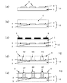
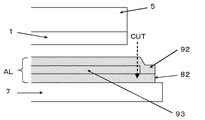
配線基板の配線が形成されていない側の面を平坦な補強板に貼り合わせた状態で、配線基板の配線が形成されている側の面に、研磨板の研磨作用面を対向配置して面方向に相対運動をさせることで摩擦力を生じさせて、前記電極部分の表面高さが均一になるように表面研磨を行った後、配線基板を前記補強板から外す配線基板の電極高さ均一化方法で、
前記配線基板の配線が形成されていない側の面を平坦な補強板と貼り合わせるのに際して、接着性を有する樹脂からなる接着層で、前記接着層に対して離型性を有する表面を備えた離型層を挟み込んだ、3層構造の積層体を用いることを特徴としている。
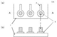
が用いられ、一般的に、ニッケル、ニッケル合金、銅、銅合金が用いられるが、それに限定されず他の導電材料であってもよく、耐食性を高めるために、金、スズ等を、その表面に積層してもよい。また、配線2および電極パッド3のパターンは、絶縁基板1上の一面を覆うように積層された前記導電材料を、パターンエッチングすることにより形成している。
2 配線
3 電極パッド
4 バンプ
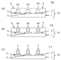
5 レジスト膜
6 露光マスク
7 補強板
8 積層フィルム
9 積層フィルム
10 配線基板
11 バンプ付き配線基板
12 レジストパターン形成基板
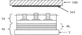
13 バンプ金属充填基板
70 基板固定用補強板
81 離型層
82 接着層
83 離型層
91 離型層
92 接着層
93 離型層
AL 積層体
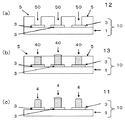
H0 所望するバンプ高さ
Claims (9)
- 絶縁基板及び絶縁基板の表面にパターン形成された配線を最小構成単位とする配線基板において、他の部品と接続または接触する電極部分の表面高さを均一化する配線基板の電極高さ均一化方法であって、
配線基板の配線が形成されていない側の面を平坦な補強板に貼り合わせた状態で、配線基板の配線が形成されている側の面に、研磨板の研磨作用面を対向配置して面方向に相対運動をさせることで摩擦力を生じさせて、前記電極部分の表面高さが均一になるように表面研磨を行った後、配線基板を前記補強板から外す配線基板の電極高さ均一化方法で、
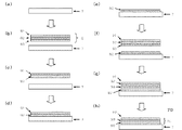
前記配線基板の配線が形成されていない側の面を平坦な補強板と貼り合わせるのに際して、接着性を有する樹脂からなる接着層で、前記接着層に対して離型性を有する表面を備えた離型層を挟み込んだ、3層構造の積層体を用いることを特徴とする配線基板の電極高さ均一化方法。 - 請求項1に記載の配線基板の電極高さ均一化方法であって、配線基板上の電極が、配線が形成されている面に開口部を有するレジスト膜を形成した後に前記開口部に金属を充填してからレジスト膜を除去して得られる突起形状を有するバンプであるとき、
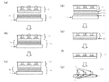
レジスト膜の開口部にバンプ用金属が充填された状態で、配線基板の配線が形成されていない側の面を平坦な補強板に貼り合わせた状態で、前記バンプ用金属を前記レジスト膜とともに表面研磨した後、前記補強板から外すとともに、レジスト膜を除去することを特徴とする配線基板の電極高さ均一化方法。 - 請求項1または請求項2に記載の配線基板の電極高さ均一化方法であって、前記絶縁基板がフレキシブル性を有するものである配線基板の電極高さ均一化方法。
- 請求項1〜3のいずれかに記載の配線基板の電極高さ均一化方法であって、前記配線基板の配線が形成されていない側の面と平坦な補強板を貼り合わせる前記積層体の、周辺部の離型層を除去して接着層同士を密着させたことを特徴とする配線基板の電極高さ均一化方法。
- 請求項1〜4いずれかに記載の配線基板の電極高さ均一化方法であって、前記補強板の厚みが0.5mm以上であることを特徴とする配線基板の電極高さ均一化方法。
- 請求項1〜5のいずれかに記載の配線基板の電極高さ均一化方法であって、前記補強板が金属板であることを特徴とする配線基板の電極高さ均一化方法。
- 請求項1〜6のいずれかに記載の配線基板の電極高さ均一化方法であって、前記補強板の、前記配線基板の配線が形成されていない側の面と貼り合わせる面を、貼り合わせを行う前に研磨して平滑化することを特徴とする配線基板の電極高さ均一化方法。
- 請求項1〜7のいずれかに記載の配線基板の電極高さ均一化方法であって、前記電極の用途がコンタクトプローブ用電極であることを特徴とする配線基板の電極高さ均一化方法。
- 絶縁基板及び絶縁基板の表面にパターン形成された配線を最小構成単位とする配線基板の製造方法であって、他の部品と接続または接触する電極部分の表面高さを、請求項1〜8のいずれかに記載の配線基板の電極高さ均一化方法により、均一化することを特徴とする配線基板の製造方法。
Priority Applications (1)
| Application Number | Priority Date | Filing Date | Title |
|---|---|---|---|
| JP2013038487A JP6132425B2 (ja) | 2013-02-28 | 2013-02-28 | 配線基板の電極高さ均一化方法およびこれを用いた配線基板の製造方法 |
Applications Claiming Priority (1)
| Application Number | Priority Date | Filing Date | Title |
|---|---|---|---|
| JP2013038487A JP6132425B2 (ja) | 2013-02-28 | 2013-02-28 | 配線基板の電極高さ均一化方法およびこれを用いた配線基板の製造方法 |
Publications (2)
| Publication Number | Publication Date |
|---|---|
| JP2014166653A JP2014166653A (ja) | 2014-09-11 |
| JP6132425B2 true JP6132425B2 (ja) | 2017-05-24 |
Family
ID=51616652
Family Applications (1)
| Application Number | Title | Priority Date | Filing Date |
|---|---|---|---|
| JP2013038487A Expired - Fee Related JP6132425B2 (ja) | 2013-02-28 | 2013-02-28 | 配線基板の電極高さ均一化方法およびこれを用いた配線基板の製造方法 |
Country Status (1)
| Country | Link |
|---|---|
| JP (1) | JP6132425B2 (ja) |
Families Citing this family (2)
| Publication number | Priority date | Publication date | Assignee | Title |
|---|---|---|---|---|
| CN105142332B (zh) * | 2015-09-18 | 2018-03-13 | 刘炜 | 一种具有导电补强结构的柔性线路板及其加工工艺 |
| JP6691816B2 (ja) * | 2016-05-18 | 2020-05-13 | 東京応化工業株式会社 | 封止体の製造方法 |
Family Cites Families (6)
| Publication number | Priority date | Publication date | Assignee | Title |
|---|---|---|---|---|
| JPH07297196A (ja) * | 1994-04-25 | 1995-11-10 | Sony Corp | バンプ電極の形成方法 |
| JP2002100651A (ja) * | 2000-09-21 | 2002-04-05 | Toppan Printing Co Ltd | 半導体装置及びその製造方法 |
| JP3875886B2 (ja) * | 2001-12-26 | 2007-01-31 | ソニーケミカル&インフォメーションデバイス株式会社 | フレキシブル配線板の製造方法 |
| JP2007243097A (ja) * | 2006-03-13 | 2007-09-20 | Matsushita Electric Ind Co Ltd | 導電性パターンの形成方法 |
| JP5152601B2 (ja) * | 2010-06-01 | 2013-02-27 | 日立化成工業株式会社 | 薄板状物品を用いた接続基板の製造方法と多層配線板の製造方法 |
| JP5650945B2 (ja) * | 2010-07-27 | 2015-01-07 | 三菱製紙株式会社 | サンドブラスト用感光性フィルム |
-
2013
- 2013-02-28 JP JP2013038487A patent/JP6132425B2/ja not_active Expired - Fee Related
Also Published As
| Publication number | Publication date |
|---|---|
| JP2014166653A (ja) | 2014-09-11 |
Similar Documents
| Publication | Publication Date | Title |
|---|---|---|
| TWI250636B (en) | A semiconductor device and its fabrication method | |
| JP4543089B2 (ja) | 半導体装置 | |
| KR101084924B1 (ko) | 반도체 장치 및 그 제조방법 | |
| JP5147677B2 (ja) | 樹脂封止パッケージの製造方法 | |
| JP4835124B2 (ja) | 半導体ic内蔵基板及びその製造方法 | |
| JP6041731B2 (ja) | インターポーザ、及び電子部品パッケージ | |
| JP5998792B2 (ja) | 半導体ic内蔵基板及びその製造方法 | |
| JP2013214713A (ja) | キャリア付き金属箔 | |
| CN101282637A (zh) | 柔性电路板表面贴装承载装置 | |
| TW201626864A (zh) | 具有高尺寸安定特性的覆蓋膜及軟性印刷電路板之製作方法 | |
| JP6132425B2 (ja) | 配線基板の電極高さ均一化方法およびこれを用いた配線基板の製造方法 | |
| TWI590726B (zh) | 電子封裝件、封裝載板及此封裝載板的製造方法 | |
| TWI362908B (ja) | ||
| JP2009182202A (ja) | 半導体装置の製造方法 | |
| JP5258838B2 (ja) | 半導体装置 | |
| JP5456113B2 (ja) | 樹脂封止パッケージ | |
| CN115915595A (zh) | 一种埋阻电路板及加工方法 | |
| JP5477372B2 (ja) | 機能素子内蔵基板、及びその製造方法、並びに電子機器 | |
| JP2009081367A (ja) | 半導体装置およびその製造方法 | |
| JP3444787B2 (ja) | 電子部品実装用フィルムキャリアテープおよび電子部品実装用フィルムキャリアテープの製造方法 | |
| KR101044133B1 (ko) | 인쇄회로기판 제조용 캐리어와 그 제조방법 및 이를 이용한 인쇄회로기판의 제조방법 | |
| JP4158659B2 (ja) | 電子部品実装回路基板の製造方法 | |
| JP5288898B2 (ja) | 接着シートの貼付装置および貼付方法、ならびに電子部品の実装装置および実装方法 | |
| KR101897609B1 (ko) | 회로 기판에서의 레진을 충진하는 방법 및 그 방법에 의해 제조된 회로 기판 | |
| JP4345464B2 (ja) | 電子部品が接合された回路基板用部材の製造方法 |
Legal Events
| Date | Code | Title | Description |
|---|---|---|---|
| A621 | Written request for application examination |
Free format text: JAPANESE INTERMEDIATE CODE: A621 Effective date: 20151225 |
|
| A977 | Report on retrieval |
Free format text: JAPANESE INTERMEDIATE CODE: A971007 Effective date: 20161026 |
|
| A131 | Notification of reasons for refusal |
Free format text: JAPANESE INTERMEDIATE CODE: A131 Effective date: 20161129 |
|
| A521 | Written amendment |
Free format text: JAPANESE INTERMEDIATE CODE: A523 Effective date: 20170120 |
|
| TRDD | Decision of grant or rejection written | ||
| A01 | Written decision to grant a patent or to grant a registration (utility model) |
Free format text: JAPANESE INTERMEDIATE CODE: A01 Effective date: 20170412 |
|
| A621 | Written request for application examination |
Free format text: JAPANESE INTERMEDIATE CODE: A621 Effective date: 20170417 |
|
| A61 | First payment of annual fees (during grant procedure) |
Free format text: JAPANESE INTERMEDIATE CODE: A61 Effective date: 20170417 |
|
| R150 | Certificate of patent or registration of utility model |
Ref document number: 6132425 Country of ref document: JP Free format text: JAPANESE INTERMEDIATE CODE: R150 |
|
| R250 | Receipt of annual fees |
Free format text: JAPANESE INTERMEDIATE CODE: R250 |
|
| LAPS | Cancellation because of no payment of annual fees |