JP4988198B2 - Rotating transmission - Google Patents
Rotating transmission Download PDFInfo
- Publication number
- JP4988198B2 JP4988198B2 JP2005500019A JP2005500019A JP4988198B2 JP 4988198 B2 JP4988198 B2 JP 4988198B2 JP 2005500019 A JP2005500019 A JP 2005500019A JP 2005500019 A JP2005500019 A JP 2005500019A JP 4988198 B2 JP4988198 B2 JP 4988198B2
- Authority
- JP
- Japan
- Prior art keywords
- transmission
- gear
- cone
- arrangement
- output
- Prior art date
- Legal status (The legal status is an assumption and is not a legal conclusion. Google has not performed a legal analysis and makes no representation as to the accuracy of the status listed.)
- Expired - Fee Related
Links
Images


Classifications
-
- F—MECHANICAL ENGINEERING; LIGHTING; HEATING; WEAPONS; BLASTING
- F16—ENGINEERING ELEMENTS AND UNITS; GENERAL MEASURES FOR PRODUCING AND MAINTAINING EFFECTIVE FUNCTIONING OF MACHINES OR INSTALLATIONS; THERMAL INSULATION IN GENERAL
- F16H—GEARING
- F16H37/00—Combinations of mechanical gearings, not provided for in groups F16H1/00 - F16H35/00
- F16H37/02—Combinations of mechanical gearings, not provided for in groups F16H1/00 - F16H35/00 comprising essentially only toothed or friction gearings
- F16H37/021—Combinations of mechanical gearings, not provided for in groups F16H1/00 - F16H35/00 comprising essentially only toothed or friction gearings toothed gearing combined with continuously variable friction gearing
- F16H37/022—Combinations of mechanical gearings, not provided for in groups F16H1/00 - F16H35/00 comprising essentially only toothed or friction gearings toothed gearing combined with continuously variable friction gearing the toothed gearing having orbital motion
-
- F—MECHANICAL ENGINEERING; LIGHTING; HEATING; WEAPONS; BLASTING
- F16—ENGINEERING ELEMENTS AND UNITS; GENERAL MEASURES FOR PRODUCING AND MAINTAINING EFFECTIVE FUNCTIONING OF MACHINES OR INSTALLATIONS; THERMAL INSULATION IN GENERAL
- F16H—GEARING
- F16H15/00—Gearings for conveying rotary motion with variable gear ratio, or for reversing rotary motion, by friction between rotary members
- F16H15/02—Gearings for conveying rotary motion with variable gear ratio, or for reversing rotary motion, by friction between rotary members without members having orbital motion
- F16H15/04—Gearings providing a continuous range of gear ratios
- F16H15/42—Gearings providing a continuous range of gear ratios in which two members co-operate by means of rings or by means of parts of endless flexible members pressed between the first mentioned members
-
- F—MECHANICAL ENGINEERING; LIGHTING; HEATING; WEAPONS; BLASTING
- F16—ENGINEERING ELEMENTS AND UNITS; GENERAL MEASURES FOR PRODUCING AND MAINTAINING EFFECTIVE FUNCTIONING OF MACHINES OR INSTALLATIONS; THERMAL INSULATION IN GENERAL
- F16H—GEARING
- F16H37/00—Combinations of mechanical gearings, not provided for in groups F16H1/00 - F16H35/00
- F16H37/02—Combinations of mechanical gearings, not provided for in groups F16H1/00 - F16H35/00 comprising essentially only toothed or friction gearings
- F16H37/021—Combinations of mechanical gearings, not provided for in groups F16H1/00 - F16H35/00 comprising essentially only toothed or friction gearings toothed gearing combined with continuously variable friction gearing
-
- F—MECHANICAL ENGINEERING; LIGHTING; HEATING; WEAPONS; BLASTING
- F16—ENGINEERING ELEMENTS AND UNITS; GENERAL MEASURES FOR PRODUCING AND MAINTAINING EFFECTIVE FUNCTIONING OF MACHINES OR INSTALLATIONS; THERMAL INSULATION IN GENERAL
- F16H—GEARING
- F16H37/00—Combinations of mechanical gearings, not provided for in groups F16H1/00 - F16H35/00
- F16H37/02—Combinations of mechanical gearings, not provided for in groups F16H1/00 - F16H35/00 comprising essentially only toothed or friction gearings
- F16H37/06—Combinations of mechanical gearings, not provided for in groups F16H1/00 - F16H35/00 comprising essentially only toothed or friction gearings with a plurality of driving or driven shafts; with arrangements for dividing torque between two or more intermediate shafts
- F16H37/08—Combinations of mechanical gearings, not provided for in groups F16H1/00 - F16H35/00 comprising essentially only toothed or friction gearings with a plurality of driving or driven shafts; with arrangements for dividing torque between two or more intermediate shafts with differential gearing
- F16H37/0833—Combinations of mechanical gearings, not provided for in groups F16H1/00 - F16H35/00 comprising essentially only toothed or friction gearings with a plurality of driving or driven shafts; with arrangements for dividing torque between two or more intermediate shafts with differential gearing with arrangements for dividing torque between two or more intermediate shafts, i.e. with two or more internal power paths
- F16H37/084—Combinations of mechanical gearings, not provided for in groups F16H1/00 - F16H35/00 comprising essentially only toothed or friction gearings with a plurality of driving or driven shafts; with arrangements for dividing torque between two or more intermediate shafts with differential gearing with arrangements for dividing torque between two or more intermediate shafts, i.e. with two or more internal power paths at least one power path being a continuously variable transmission, i.e. CVT
- F16H37/0853—CVT using friction between rotary members having a first member of uniform effective diameter cooperating with different parts of a second member
-
- F—MECHANICAL ENGINEERING; LIGHTING; HEATING; WEAPONS; BLASTING
- F16—ENGINEERING ELEMENTS AND UNITS; GENERAL MEASURES FOR PRODUCING AND MAINTAINING EFFECTIVE FUNCTIONING OF MACHINES OR INSTALLATIONS; THERMAL INSULATION IN GENERAL
- F16H—GEARING
- F16H37/00—Combinations of mechanical gearings, not provided for in groups F16H1/00 - F16H35/00
- F16H37/02—Combinations of mechanical gearings, not provided for in groups F16H1/00 - F16H35/00 comprising essentially only toothed or friction gearings
- F16H37/06—Combinations of mechanical gearings, not provided for in groups F16H1/00 - F16H35/00 comprising essentially only toothed or friction gearings with a plurality of driving or driven shafts; with arrangements for dividing torque between two or more intermediate shafts
- F16H37/08—Combinations of mechanical gearings, not provided for in groups F16H1/00 - F16H35/00 comprising essentially only toothed or friction gearings with a plurality of driving or driven shafts; with arrangements for dividing torque between two or more intermediate shafts with differential gearing
- F16H37/0833—Combinations of mechanical gearings, not provided for in groups F16H1/00 - F16H35/00 comprising essentially only toothed or friction gearings with a plurality of driving or driven shafts; with arrangements for dividing torque between two or more intermediate shafts with differential gearing with arrangements for dividing torque between two or more intermediate shafts, i.e. with two or more internal power paths
- F16H37/084—Combinations of mechanical gearings, not provided for in groups F16H1/00 - F16H35/00 comprising essentially only toothed or friction gearings with a plurality of driving or driven shafts; with arrangements for dividing torque between two or more intermediate shafts with differential gearing with arrangements for dividing torque between two or more intermediate shafts, i.e. with two or more internal power paths at least one power path being a continuously variable transmission, i.e. CVT
- F16H37/086—CVT using two coaxial friction members cooperating with at least one intermediate friction member
-
- F—MECHANICAL ENGINEERING; LIGHTING; HEATING; WEAPONS; BLASTING
- F16—ENGINEERING ELEMENTS AND UNITS; GENERAL MEASURES FOR PRODUCING AND MAINTAINING EFFECTIVE FUNCTIONING OF MACHINES OR INSTALLATIONS; THERMAL INSULATION IN GENERAL
- F16H—GEARING
- F16H61/00—Control functions within control units of change-speed- or reversing-gearings for conveying rotary motion ; Control of exclusively fluid gearing, friction gearing, gearings with endless flexible members or other particular types of gearing
- F16H61/66—Control functions within control units of change-speed- or reversing-gearings for conveying rotary motion ; Control of exclusively fluid gearing, friction gearing, gearings with endless flexible members or other particular types of gearing specially adapted for continuously variable gearings
- F16H61/662—Control functions within control units of change-speed- or reversing-gearings for conveying rotary motion ; Control of exclusively fluid gearing, friction gearing, gearings with endless flexible members or other particular types of gearing specially adapted for continuously variable gearings with endless flexible members
- F16H61/66272—Control functions within control units of change-speed- or reversing-gearings for conveying rotary motion ; Control of exclusively fluid gearing, friction gearing, gearings with endless flexible members or other particular types of gearing specially adapted for continuously variable gearings with endless flexible members characterised by means for controlling the torque transmitting capability of the gearing
-
- F—MECHANICAL ENGINEERING; LIGHTING; HEATING; WEAPONS; BLASTING
- F16—ENGINEERING ELEMENTS AND UNITS; GENERAL MEASURES FOR PRODUCING AND MAINTAINING EFFECTIVE FUNCTIONING OF MACHINES OR INSTALLATIONS; THERMAL INSULATION IN GENERAL
- F16H—GEARING
- F16H48/00—Differential gearings
- F16H48/06—Differential gearings with gears having orbital motion
- F16H48/08—Differential gearings with gears having orbital motion comprising bevel gears
-
- F—MECHANICAL ENGINEERING; LIGHTING; HEATING; WEAPONS; BLASTING
- F16—ENGINEERING ELEMENTS AND UNITS; GENERAL MEASURES FOR PRODUCING AND MAINTAINING EFFECTIVE FUNCTIONING OF MACHINES OR INSTALLATIONS; THERMAL INSULATION IN GENERAL
- F16H—GEARING
- F16H57/00—General details of gearing
- F16H57/04—Features relating to lubrication or cooling or heating
- F16H57/048—Type of gearings to be lubricated, cooled or heated
- F16H57/0487—Friction gearings
- F16H57/0491—Friction gearings of the cone ring type
-
- F—MECHANICAL ENGINEERING; LIGHTING; HEATING; WEAPONS; BLASTING
- F16—ENGINEERING ELEMENTS AND UNITS; GENERAL MEASURES FOR PRODUCING AND MAINTAINING EFFECTIVE FUNCTIONING OF MACHINES OR INSTALLATIONS; THERMAL INSULATION IN GENERAL
- F16H—GEARING
- F16H61/00—Control functions within control units of change-speed- or reversing-gearings for conveying rotary motion ; Control of exclusively fluid gearing, friction gearing, gearings with endless flexible members or other particular types of gearing
- F16H61/66—Control functions within control units of change-speed- or reversing-gearings for conveying rotary motion ; Control of exclusively fluid gearing, friction gearing, gearings with endless flexible members or other particular types of gearing specially adapted for continuously variable gearings
- F16H61/664—Friction gearings
- F16H61/6649—Friction gearings characterised by the means for controlling the torque transmitting capability of the gearing
-
- Y—GENERAL TAGGING OF NEW TECHNOLOGICAL DEVELOPMENTS; GENERAL TAGGING OF CROSS-SECTIONAL TECHNOLOGIES SPANNING OVER SEVERAL SECTIONS OF THE IPC; TECHNICAL SUBJECTS COVERED BY FORMER USPC CROSS-REFERENCE ART COLLECTIONS [XRACs] AND DIGESTS
- Y10—TECHNICAL SUBJECTS COVERED BY FORMER USPC
- Y10T—TECHNICAL SUBJECTS COVERED BY FORMER US CLASSIFICATION
- Y10T74/00—Machine element or mechanism
- Y10T74/19—Gearing
- Y10T74/19219—Interchangeably locked
- Y10T74/19293—Longitudinally slidable
- Y10T74/19335—Single spur gear
- Y10T74/1934—Tumbler and cone
- Y10T74/19344—Multiple cone
Landscapes
- Engineering & Computer Science (AREA)
- General Engineering & Computer Science (AREA)
- Mechanical Engineering (AREA)
- Friction Gearing (AREA)
- Transmission Devices (AREA)
- Lubricants (AREA)
- Developing Agents For Electrophotography (AREA)
- Retarders (AREA)
- General Details Of Gearings (AREA)
Description
本発明は、摩擦でトルクを伝達することができる少なくとも2つの回転変速要素を有する回転変速機に関する。特に、本発明は、それぞれが2つの回転変速要素を連結する回転結合要素のため、少なくとも1つの動作表面を有する2つの回転変速要素を具備する変速機に関する。2つの回転変速要素の動作表面のうちの少なくとも1つは、この場合、異なる稼動半径を有する結合要素のための少なくとも2つの動作経路を好ましくは有するので、このように、連続的なおよび/またはほとんど無段変速が実行されることができる。
例えば、このタイプの配置は、コーン形の摩擦リング変速に関するEP0 878 641 A1から公知である。そこにおいて、対向するコーン形の角度を有する2つのコーンが取り付けられるので、それらの間に恒常的な距離が残るように回転することができ、かつ、リングは結合要素としてコーンのうちの1つを囲んで回転する。しかしながら、このタイプの配置が比較的大きな摩耗、および/または、不十分な変速パフォーマンスのみ、および/または、特に、より高い負荷で変速機の破壊に至ることが示された。
したがって、本発明の目的は、摩擦でトルクを伝達することができ、よりよい変速挙動、および/または、より長い耐用年数を有する少なくとも2つの回転変速要素を具備する回転変速機を提供することである。
The present invention relates to a rotary transmission having at least two rotary transmission elements capable of transmitting torque by friction. In particular, the invention relates to a transmission comprising two rotary transmission elements each having at least one operating surface, because of the rotary coupling elements each connecting two rotary transmission elements. Since at least one of the operating surfaces of the two rotary transmission elements preferably in this case has at least two operating paths for coupling elements having different working radii, in this way, continuous and / or Almost continuously variable transmission can be performed.
For example, this type of arrangement is known from EP 0 878 641 A1 for cone-shaped friction ring transmission. There, two cones with opposing cone-shaped angles are mounted so that they can be rotated so that a constant distance remains between them, and the ring is one of the cones as a coupling element Rotate around. However, this type of arrangement has been shown to result in relatively high wear and / or poor gear shifting performance only and / or particularly at higher loads resulting in transmission failure.
Accordingly, an object of the present invention is to provide a rotary transmission comprising at least two rotary transmission elements that can transmit torque by friction and have a better shifting behavior and / or a longer service life. is there.
この目的を達成するために、本発明は摩擦でトルクを伝達することができる少なくとも2つの回転変速要素を有する回転変速機を提案する。そこにおいて、少なくとも動作の間、隙間は変速要素の間で提供される。
このタイプの遠隔操作可能な動作を通じて、このタイプの変速機は、極めて低い摩耗によって組み込まれ、適切な相互作用メカニズムは、対応する変速要素と力および/またはトルク変速機のための結合要素との間で提供されている。好ましくは、圧力にもかかわらず隙間において残存したままで、必要な力および/またはトルクを伝達する流体および/または液体を経た結合は提供される。しかしながら、例えば静電または磁性の配置のような他の相互作用メカニズムもまた提供されてもよい。
To achieve this object, the present invention proposes a rotary transmission having at least two rotary transmission elements capable of transmitting torque with friction. There, a gap is provided between the transmission elements at least during operation.
Through this type of remotely operable operation, this type of transmission is incorporated with very low wear, and an appropriate interaction mechanism is between the corresponding transmission element and the coupling element for the force and / or torque transmission. Is offered between. Preferably, a coupling via fluid and / or liquid that provides the necessary force and / or torque while remaining in the gap despite pressure is provided. However, other interaction mechanisms such as electrostatic or magnetic arrangements may also be provided.
本発明は、隙間および/または液体が少なくとも動作の間、コーンと摩擦リングとの間に置かれたコーン形の摩擦リング変速機のために特に適切である。このように、他に何もしなくともリングはまた、所望の速度伝達比のために配置されることができる。本発明は、しかしながら、変速要素が互いに摩擦で相互に作用する他の無段変速機にもまた、適切である。現在の文脈において、変速要素間の「摩擦の相互関係」という用語は、一方の変速要素からこの目的のためにこれらの変速要素の間に存在している明確な接続なしで他方の変速要素までトルクが伝達される相互関係を表現する。一般的に、比較的高制限のトルクより少なくとも上に、特定のスリップは摩擦の相互関係において存在する。このタイプのスリップは、非破壊的にしばしば発生し、そして、対応する変速機は、概してこれらの制限トルク以下で機能する。 The invention is particularly suitable for cone-shaped friction ring transmissions in which the gap and / or liquid is placed between the cone and the friction ring at least during operation. In this way, the ring can also be arranged for the desired speed transmission ratio without doing anything else. However, the invention is also suitable for other continuously variable transmissions in which the transmission elements interact with each other by friction. In the current context, the term “friction interrelationship” between transmission elements refers to the transmission elements from one transmission element to the other without the explicit connection that exists between these transmission elements for this purpose. Represents the mutual relationship in which torque is transmitted. Generally, at least above a relatively high limiting torque, a particular slip exists in a frictional relationship. This type of slip often occurs non-destructively and the corresponding transmission generally functions below these limiting torques.
代替的におよび/または累積的に、回転変速要素、および/または、摩擦リングのような結合要素の少なくとも1つが湿らされる液体として、メチル・シロキサン、ジメチル・ジフェニル・シロキサンおよび/またはフェニル基を有するメチル・フェニル・シロキサンからなる液体、特にシリコーンオイルは、上記の隙間に使用されることができる。特に、例えばフェニル・アルキル基またはフルオロアルキル基を含むジメチル・ポリシロキサンも使用されることができる。この場合、ジメチル・シロキシ基は、特にその中において個別にジフェニル・シロキシ基と、または、シロキサン・ブロックとして代替されることができる。
このタイプの液体は、用語「シリコーンオイル」として一般に公知であり、また、具体的にではないが、概して無段変速機の回転変速要素を湿らすための液体として、EP0 878 641 A1において開示されている。シリコーンオイルは、実地試験において、特に結合ローラまたは摩擦リングのような圧延結合要素での相互作用において、不都合であることが示された比較的軽微な潤滑性能を有するので、周知のシリコーンオイルでの動作の間、液体フィルムが壊れることが仮定される。しかしながら、シリコーンオイルは、他の液体と比較してその特性の高温担持能力において特に優れている。
Alternatively and / or cumulatively, methyl siloxane, dimethyl diphenyl siloxane and / or phenyl groups may be used as a liquid in which at least one of the rotational transmission element and / or the coupling element such as a friction ring is moistened. A liquid comprising methyl phenyl siloxane, particularly silicone oil, can be used in the gap. In particular, dimethyl polysiloxanes containing, for example, phenyl alkyl groups or fluoroalkyl groups can also be used. In this case, the dimethylsiloxy groups can be replaced in particular individually as diphenylsiloxy groups or as siloxane blocks.
This type of liquid is commonly known as the term “silicone oil” and is disclosed in EP 0 878 641 A1 as a liquid for generally but not specifically moistening the rotary transmission element of a continuously variable transmission. ing. Silicone oils have relatively minor lubrication performance that has been shown to be inconvenient in field tests, particularly in interaction with rolling coupling elements such as coupling rollers or friction rings, and so with known silicone oils. It is assumed that the liquid film breaks during operation. However, silicone oil is particularly superior in its high-temperature carrying capacity compared to other liquids.
メチル・シロキサン、ジメチル・ジフェニル・シロキサンおよび/またはフェニル基を有するメチル・フェニル・シロキサンから成る提案された液体は、特に、例えばジフェニル・シロキサン・ブロックがポリメチル・シロキサンに組み込まれる場合、おそらくフィルムの破損を防ぐ他の液体と比較して高い圧縮性において優れている。したがってオイルは、圧延結合要素を有する変速機のために温度/粘性および/または温度/圧縮性挙動において、このタイプのシステムのために見つけられた都合がよい挙動を有して提供され、その粘性および/または圧縮性は、温度に依存する粘性変化度および/または圧縮性変化度が変わるいかなるタイプもの液体であって、鉱油の粘性変化度および/または圧縮性変化度とジメチル・シロキサンの粘性変化度および/または圧縮性変化度との間にある液体は、非常に一般的に変速機に都合よく使用される。これらの特性を使用して、液体および/またはオイルは対応する変速機を十分になめらかにするので、高過ぎる運転温度に達しない。加えて、潤滑剤は、結合要素と対応する変速要素との間の十分な結合が妨げられるほど強くない。その上に、記載された圧縮性ウインドウは、加圧下でさえ液体の均一的な分配を妨げることなく部品を囲んでいる液体フィルムの十分な安定性を生じる。 Proposed liquids consisting of methyl siloxane, dimethyl diphenyl siloxane and / or methyl phenyl siloxane with phenyl groups are likely to break the film, especially when diphenyl siloxane blocks are incorporated into polymethyl siloxane, for example. It is excellent in high compressibility compared with other liquids. The oil is therefore provided with a favorable behavior found for this type of system in temperature / viscosity and / or temperature / compressibility behavior for transmissions with rolling coupling elements, and its viscosity And / or compressibility is any type of liquid whose temperature-dependent viscosity change and / or compressibility change varies, such as mineral oil viscosity change and / or compressibility change and dimethyl siloxane viscosity change Liquids that are between degrees and / or compressive changes are very commonly used in transmissions. Using these properties, liquids and / or oils will smooth the corresponding transmission sufficiently so that the operating temperature is not too high. In addition, the lubricant is not strong enough to prevent sufficient coupling between the coupling element and the corresponding transmission element. Moreover, the described compressible window provides sufficient stability of the liquid film surrounding the part without disturbing the uniform distribution of the liquid even under pressure.
特に、ポリジメチル・シロキサン、ポリジメチル・ジフェニル・シロキサン、および/またはポリメチル・フェニル基を有するフェニル・シロキサン、および/または、アルキル置換γ-トリフルオロプロピル置換ポリジメチル・シロキサンを有する液体が使用されることができる。
「シリコーン」はまた、例えば10から25%のフェニル基またはγ-トリフルオロプロピル基または他のアルキル基も、使用されるポリジメチル・シロキサンの置換基として含まれるような有機置換基において使用されることができる。
加えて、対応する液体が温度に関して安定し、かつ、可能な限り、鉱油よりその特性に関する変更が少ない場合、累積的におよび/または代替的に特に都合がよい。このように、対応する流体はより変質しないので、変速機の長い耐用年数は保証されることができる。さらに、例えば極めて高い負荷または極めて高速、または、冬における始動手順の間のような異なる作動状態においてさえ、流体の物理的な特性はできるだけ一定に保たれる。
ポリジメチル・シロキサンのフェニル・シロキサン・ユニットに関して、および/または、一般にシロキサンにおけるフェニル・シロキサン・ユニットに関して、それらは、所望の結果を達成するため、対とブロックとの両方において使用されることができる。加えて、上記した圧縮性は、結合要素と回転変速要素との間に残り、対応する液体で満たされ、かつ、高圧においてさえ液体により安定して架橋される隙間と協動して特に都合がよい。この場合、液体は力伝達のために使用されるので、本願明細書において起こっている剪断力は、積極的にではないが結合要素と対応する変速要素とを結合することができる。その上に、高い圧縮性は、小さい隙間のみが十分に高い剪断力および壊れない液体フィルムを実行し、また、隙間は、高圧およびこの高圧力に対する液体の高抵抗力のみにより維持されることが可能であるこの変速機が高いおよび/またはより高いトルクにおいてさえ可能であることを保証する。
In particular, liquids having polydimethyl siloxane, polydimethyl diphenyl siloxane, and / or phenyl siloxane having polymethyl phenyl groups, and / or alkyl-substituted γ-trifluoropropyl-substituted polydimethyl siloxane are used. be able to.
“Silicone” is also used in organic substituents such that, for example, 10 to 25% of phenyl groups or γ-trifluoropropyl groups or other alkyl groups are also included as substituents of the polydimethylsiloxane used. be able to.
In addition, it is particularly advantageous cumulatively and / or alternatively if the corresponding liquid is stable with respect to temperature and, where possible, has less change in its properties than mineral oil. In this way, the long service life of the transmission can be guaranteed since the corresponding fluid is less altered. Moreover, the physical properties of the fluid are kept as constant as possible, even at different operating conditions, for example during very high loads or very high speeds or during start-up procedures in winter.
With respect to phenyl siloxane units of polydimethyl siloxane and / or with respect to phenyl siloxane units generally in siloxanes, they can be used in both pairs and blocks to achieve the desired results. . In addition, the compressibility described above is particularly advantageous in cooperation with gaps that remain between the coupling element and the rotary transmission element, are filled with the corresponding liquid, and are stably cross-linked by the liquid even at high pressure. Good. In this case, since the liquid is used for force transmission, the shear forces occurring herein can couple the coupling element and the corresponding transmission element, albeit not aggressively. Moreover, high compressibility means that only a small gap performs a sufficiently high shear force and a liquid film that does not break, and that the gap is maintained only by the high pressure and the high resistance of the liquid to this high pressure. This transmission that is possible ensures that it is possible even at high and / or higher torques.
温度安定性、圧縮性および/または粘性に関する隙間および/または液体に関する上述の考慮すべき問題は、個別にまたは共に連続変速のため、特に互いの上で回転する2つの変速要素を有する変速機のため、本発明による変速機の残りの特徴のそれぞれにさえ都合よい可能性があることは明らかである。
特に摩擦ロック装置、または油圧、流体静力学的、流体力学的、磁性または別の遠隔操作可能な相互作用、および/または明確な接続のない他の相互作用を経てさえ本質的に連結される変速要素のため、結合要素の変速要素の2つの動作経路からなる変速機において、これらの動作経路は、相互作用、例えば、適切な方法における表面圧または同様の何かを実行および/または適応させることを可能にするため、異なる表面を備える場合、都合がよい可能性がある。この場合、例えば、異なる幅および/または異なる表面組織および/または表面処理の溝または突起は、回転変速要素の少なくとも1つに沿って提供される。このように例えば、表面圧は変速要素の異なる半径に適応する。このタイプの表面のバリエーションが変速要素上の動作経路において都合がよいことは、本発明による変速機の残りの特徴のそれぞれにさえ明らかである。
The above-mentioned considerations regarding gaps and / or liquids relating to temperature stability, compressibility and / or viscosity are for a transmission with two transmission elements which rotate individually or together, in particular for continuous transmission. Thus, it is clear that even each of the remaining features of the transmission according to the present invention may be advantageous.
Shifts that are inherently coupled even in particular via friction locking devices or hydraulic, hydrostatic, hydrodynamic, magnetic or other remotely operable interactions and / or other interactions without a clear connection For elements, in a transmission consisting of two operating paths of a transmission element of a coupling element, these operating paths perform and / or adapt interactions, eg surface pressure or something similar in an appropriate manner. It may be convenient to provide different surfaces to enable In this case, for example, different widths and / or different surface textures and / or surface treatment grooves or protrusions are provided along at least one of the rotary transmission elements. Thus, for example, the surface pressure adapts to different radii of the transmission element. It is clear even for each of the remaining features of the transmission according to the invention that this type of surface variation is advantageous in the operating path on the transmission element.
動作経路から独立している相互作用の実施例のために、結合要素の表面はまた、仕上げがなめらかでなければならない。特に、表面は油圧相互作用の場合には適切な方法の剪断および圧縮力に影響するために溝または類似した何かを有することができる。加えて、結合要素はまた、接触している異なる変速要素のための異なる表面を有することができる。
よい剪断力の分配を保証するため、特に、液体フィルムが破損せずに結合要素の動作表面および/または対応する変速要素の対応する動作表面を湿らす液体との相互作用において、結合要素は、直線から逸脱する横断面を有する少なくとも1つの動作表面を有することができ、好ましくは凸面および/または冠部を持つ横断面を有する。十分な剪断力を伝達する連続液体フィルムは、したがって高圧においてでさえ保証されることができる。この場合、横断面の選択は、好ましくは液体に合わせて調整される。累積的におよび/または代替的に、結合要素の横断面は、特に下記のように、保持装置により片側のみ保持される直線から最適に逸脱することができる。なぜなら、このタイプの片側の保持装置は、結合要素に比較的大きい自由度を残すにもかかわらず結合要素と安定する方法で相互に作用することができ、直線から逸脱している動作表面により比較的不安定であるので、特に動作経路が変更する場合には、全体的なシステムはまた、低い力消費によって作動されることができるからである。
For interactive embodiments that are independent of the operating path, the surface of the coupling element must also have a smooth finish. In particular, the surface can have grooves or something similar to influence shear and compressive forces in an appropriate manner in the case of hydraulic interactions. In addition, the coupling element can also have different surfaces for different shifting elements in contact.
In order to ensure good shear force distribution, in particular in the interaction with the liquid that wets the working surface of the coupling element and / or the corresponding working surface of the corresponding transmission element without breaking the liquid film, It can have at least one working surface with a cross section deviating from a straight line, preferably with a cross section with a convex surface and / or crown. A continuous liquid film that transmits sufficient shear can therefore be guaranteed even at high pressures. In this case, the selection of the cross section is preferably adjusted to the liquid. Cumulatively and / or alternatively, the cross-section of the coupling element can deviate optimally from a straight line held only on one side by the holding device, in particular as described below. Because this type of one-sided holding device can interact with the coupling element in a stable manner, while leaving a relatively large degree of freedom in the coupling element, compared by a working surface deviating from a straight line Because the overall system can also be operated with low power consumption, especially if the operating path changes.
結合要素の表面デザインおよび/またはこのタイプの回転変速要素が、変速要素と結合要素との間に相互作用させるため、本発明による変速装置の残りの特徴に個別に、また都合よく使用されることができることは明らかである。
無段部分変速機を有する変速機において、特別な運転状況、例えば低速運転の間における後退用ギア、および/または、恒常的な安定した負荷がかかる間における課題の減少を保証するため、並列に結合される2つ変速経路で優れている無段部分変速機を有する変速機が提案され、無段部分変速機は、2つの変速経路の第1の経路において提供されている。
このタイプの配置は、第1の変速経路が無段変速機の利点を提供することができる一方で、特別な運転、および/または、負荷の状況が第2の変速経路により実行されることを可能にする。現在の文脈において、「2つの変速経路の並列回路」という用語は、共有されたインプット側の部分的な変速機間において、2つの変速経路が、例えば駆動軸のモータ、クラッチディスク、または類似した何か、および、共有されたアウトプット側の部分的な変速機、また、例えば自動車の主な差動装置のような(原文にてword missing)を有することを示す。共有されたインプット側の部分的な変速機と共有されたアウトプット側の部分的な変速機との間の、2つの変速経路は、このように異なる条件を満たすために、同時に交互に付加的におよび/または差別的に作動される。このタイプの配置が本発明の残りの特徴のそれぞれにさえ都合がよいことは、明らかである。
The surface design of the coupling element and / or this type of rotational transmission element is used individually and conveniently for the remaining features of the transmission according to the invention for interacting between the transmission element and the coupling element. Obviously you can.
In transmissions with continuously variable partial transmissions, in parallel to ensure reduction of problems during special driving situations, for example reverse gear during low speed operation and / or constant steady load A transmission having a continuously variable partial transmission that excels in two coupled transmission paths is proposed, and the continuously variable partial transmission is provided in a first of the two transmission paths.
This type of arrangement makes it possible for the first shift path to provide the benefits of a continuously variable transmission while special driving and / or load conditions are performed by the second shift path. enable. In the current context, the term “parallel circuit of two transmission paths” means that between two transmissions on a shared input side, the two transmission paths are, for example, a drive shaft motor, a clutch disk, or similar. Indicates something and a shared partial transmission on the output side, as well as the main differential of a car, for example (word missing). The two shift paths between the shared input-side partial transmission and the shared output-side partial transmission are alternately and alternately added to satisfy the different conditions in this way. And / or differentially actuated. It is clear that this type of arrangement is advantageous even for each of the remaining features of the present invention.
したがって、後退用ギア、第1ギアおよび/またはオーバードライブが、2つの変速経路の第2の経路に提供される場合、都合がよい可能性がある。これらの状況のため、無段変速機は、制限された方法かつ比較的大きい出費によってのみ使用可能であり、および/または、特にオーバードライブ、すなわち、高速および低トルクにおいて、大きい損失を受けさせられる。
少なくとも1つのフリーホイールが2つの変速経路の間で提供される場合、これらの変速経路は、複合の切替の出費なしでおよび/または複合の切替および調整技術なしで共に導かれることができる。
Therefore, it may be advantageous if the reverse gear, the first gear and / or the overdrive are provided in the second path of the two shift paths. Because of these situations, continuously variable transmissions can only be used in a limited way and with relatively large expenditures and / or are subject to large losses, especially in overdrive, i.e. at high speeds and low torques. .
If at least one freewheel is provided between two shift paths, these shift paths can be routed together without the expense of complex switching and / or without complex switching and adjustment techniques.
累積的におよび/または代替的に、連続的に可変の部分的な変速装置からなる変速機において、後者は、差動ギア部分または遊星ギア部分のような2つの電力分割器の間に位置することができ、連続的に可変の部分的な変速機の少なくとも1つのインプットは、インプット側の電力分割器の少なくとも1つのアウトプットに機械的に結合され、連続的に可変の部分的な変速機の少なくとも1つのアウトプットは、アウトプット側の電力分割器の少なくとも1つのインプットに機械的に結合されている。このタイプの配置を通じて、トルク変速機は、実行されることができるので、それは拡大されることができ、および/または、無段部分変速の調整範囲が拡張されることができる。このことは、2つの電力分割器が自然に損失に至るので、現行の知識に従って効率を犠牲にして起こることである。しかしながら、このタイプの配置は、連続変速機のための用途の幅の有意な増加を許容する。さらに、無段部分変速で処理されなければならないトルクはしたがって、損失が適切な実施で制限内に保たれるように減少することができる。なぜなら、無段変速機の低いトルクは、特にそれがコーン形の摩擦リング変速機である場合、より低い損失に導き、そこで電力分割器における損失を対応して減少することができるからである。
累積的におよび/または代替的に、少なくとも1つの前進用ギアと少なくとも1つの後退用ギアとを備え、独立して連続変速機が存在する変速機において、この前進用ギアとこの後退用ギアとを実行する差動ギアが提供されることができ、差動ギア部分の少なくとも1つのアセンブリは、ハウジング、および/または、差動ギア部分の他のアセンブリで交互に固定されることが可能である。このように、差動ギアの差動アセンブリがインプットとして使用されるように、前進用ギアおよび後退用ギアを有する変速機は、非常にコンパクトに実現されることができる。差動装置の中央アセンブリがそれから第2の差動アセンブリに結合される場合、1つの回転方向が実行される。対照的に、第2の差動アセンブリおよび/または差動装置の中央アセンブリがハウジングに結合され、このように固定された場合、固定されていない他のアセンブリは、上述したギア反転が実行されるその回転方向を変える。このような方法で、前進用ギアおよび後退用ギアを有する変速機は、特にコンパクトに実現されることができる。
Cumulatively and / or alternatively, in a transmission consisting of a continuously variable partial transmission, the latter is located between two power dividers such as a differential gear part or a planetary gear part. And the at least one input of the continuously variable partial transmission is mechanically coupled to at least one output of the power divider on the input side, and the continuously variable partial transmission At least one output is mechanically coupled to at least one input of the output power divider. Through this type of arrangement, the torque transmission can be implemented, so it can be expanded and / or the adjustable range of the continuously variable partial transmission can be expanded. This is what happens at the expense of efficiency in accordance with current knowledge, since the two power dividers are naturally lossy. However, this type of arrangement allows a significant increase in the range of applications for continuous transmissions. Furthermore, the torque that must be handled with a continuously variable partial shift can therefore be reduced so that the loss is kept within limits with proper implementation. This is because the low torque of a continuously variable transmission leads to lower losses, especially if it is a cone-shaped friction ring transmission, where losses in the power divider can be correspondingly reduced.
Cumulatively and / or alternatively, in a transmission comprising at least one forward gear and at least one reverse gear, wherein there is an independent continuous transmission, the forward gear and the reverse gear Can be provided, wherein at least one assembly of the differential gear portion can be alternately fixed with the housing and / or other assemblies of the differential gear portion. . In this way, the transmission with the forward gear and the reverse gear can be realized very compactly, such that the differential assembly of the differential gear is used as an input. When the central assembly of the differential is then coupled to the second differential assembly, one direction of rotation is performed. In contrast, if the second differential assembly and / or the central assembly of the differential is coupled to the housing and thus secured, the other unsecured assemblies will perform the gear reversal described above. Change its direction of rotation. In this way, a transmission having a forward gear and a reverse gear can be realized particularly compactly.
加えて、累積的におよび/または代替的に、切替ギア部分を経た変速経路に交互に切替えられることができる少なくとも2つの変速段階を備える変速機が提案され、2つの変速段階の第1の段階は、無段部分変速を有する。このタイプの配置は、最初はシステムに反するように見える。なぜなら、連続変速はいかなるタイプもの切替を省くことが可能であるために備えられるからである。しかしながら、このタイプの配置は、その利点が実際に優れている場合にのみ、連続変速を許容する。例えば、比較的高いトルクは運転開始の間しばしば発生する、そして有意に連続変速を供給し、および/または、連続変速機の極端に大きい設計を必要とする。したがって、例えば別々に第1ギアを実行し、運転開始の後、無段部分変速を結合するだけであることは都合がよい。この場合、無段部分変速は、2つの変速段階の一方から他方への切替手順の前に、第2の変速段階の速度は、第1の変速段階の速度へと無段変速機によって適応するような方法で特に必要な大きさにされるので、第1の変速段階から第2の変速段階まで、および/または、第2の変速段階から第1の変速段階までの移行は、本質的に連続的に発生することができる。このように、連続無段変速機の利点は、運転開始の間、例えば起こることができるので、不利な点を受け入れる必要なく最適に利用されることができる。
これはまた、本質的に一定のアウトプットを有する、および/または、本質的に一定のトルクを有する状況において、速度変更はモータの速度変更により実行されることができるので、無段部分変速は本質的に不可欠ではないということはあてはまる。このタイプの作動状況において、無段部分変速は、結合された変速段階によって避けられる典型的に高い損失−例えばスリップにより生じる−を有する。切替はまたこの場合、運転の時点で実行されることが可能である。ここで、このタイプの段階変更は、自動車乗員に目立たないかまたはわずかに目立つだけである。特に、無段変速機はこの目的のために適切な作動状況に導かれることができる。例えば、フリーホイール経由でのこのタイプの変速段階の係合および/または分離も考えられる。
In addition, a transmission comprising at least two shift stages that can be switched cumulatively and / or alternatively to a shift path via a switching gear portion is proposed, and the first stage of the two shift stages Has a continuously variable transmission. This type of arrangement initially appears to be against the system. This is because continuous shifting is provided because any type of switching can be omitted. However, this type of arrangement only allows continuous shifting if the advantage is actually superior. For example, relatively high torque often occurs during start-up and provides a significantly continuous shift and / or requires an extremely large design of the continuous transmission. Thus, for example, it is convenient to execute the first gear separately and only combine the continuously variable partial shift after the start of operation. In this case, the continuously variable partial shift is adapted by the continuously variable transmission to the speed of the first shift stage before the switching procedure from one of the two shift stages to the other. In particular, the transition from the first shift stage to the second shift stage and / or from the second shift stage to the first shift stage is essentially It can be generated continuously. In this way, the advantages of a continuously variable transmission can occur, for example, during start-up, so that it can be used optimally without having to accept the disadvantages.
This is also because in a situation with an essentially constant output and / or with an essentially constant torque, the speed change can be performed by changing the speed of the motor so It is true that it is not essential in nature. In this type of operating situation, a continuously variable partial shift typically has a high loss, eg caused by slip, which is avoided by a combined shift stage. Switching can also be carried out in this case at the time of operation. Here, this type of phase change is inconspicuous or only slightly noticeable to the vehicle occupant. In particular, the continuously variable transmission can be led to an appropriate operating situation for this purpose. For example, engagement and / or disengagement of this type of shift stage via freewheels is also conceivable.
加えて、無段部分変速からなる変速段階に加えて係合されることができる変速段階は、例えば前進用ギアと後退用ギアとの間、および、運転開始ギアを切り替えるために使用される差動ギア要素を備えることができる。特にこのタイプの実施例において、前進と後退用ギアとの間で切り替えをするために必要である差動ギア要素のアセンブリが摩擦クラッチを経て固定する場合、可能な限りの最も細かくかつ均一である切替が実行されることができるということは都合がよい。
切替ギア部分を経て変速経路に交互に切替えられる2つの変速段階を有する変速機において、2つの変速段階の第1の段階は、無段部分変速を備え、切替ギア部分は、無段部分変速をトリロクコンバータ、または、モータアウトプットシャフトに直接結合した他のアセンブリのポンプホイールに連結することができ、そして、第2の変速段階は、トリロクコンバータのタービンホイール、または、他の接続可能なモータアウトプットアセンブリに連結することができる。このように、特に通常の動作状態においてモータアウトプットは、無段部分変速に直接伝導されることができる。その一方で、特に運転開始手順の間、高トルクが第2の変速段階に伝達されることができるので、それは無段部分変速に関連して外される。これは特に、トルク・オーバーロードが自然に発生し、別途有意に無段部分変速を供給するトリロクコンバータのタービンホイールとの相互作用において特にあてはまる。
In addition, the shift stage that can be engaged in addition to the shift stage consisting of a continuously variable partial shift is the difference used, for example, between the forward gear and the reverse gear and for switching the start gear. A moving gear element can be provided. Particularly in this type of embodiment, the differential gear element assembly required to switch between forward and reverse gears is the finest and most uniform possible when fixed via a friction clutch. Conveniently, switching can be performed.
In a transmission having two shift stages that are alternately switched to a shift path via a switching gear portion, the first of the two shift stages includes a continuously variable partial shift, and the switching gear portion performs a continuously variable partial shift. Can be coupled to a tri-wheel converter or other assembly pump wheel directly coupled to the motor output shaft, and the second shift stage can be a tri-wheel converter turbine wheel or other connectable motor Can be connected to an output assembly. In this way, the motor output can be directly conducted to the continuously variable transmission, particularly in normal operating conditions. On the other hand, especially during the start-up procedure, high torque can be transmitted to the second shift stage, so it is removed in connection with the continuously variable partial shift. This is especially true in the interaction with the turbine wheel of the triloc converter where torque overload occurs naturally and provides a separate and stepless partial shift.
特に電動モータと結合して、同軸的に配置された駆動およびアウトプットを有する無段部分変速は、このタイプの配置において、ハウジングに作用しているトルクが特にコンパクトな方法で最小化されることができるので、本発明による変速機の残りの特徴から独立してさえも都合がよい。好ましくは、差動ギア部分は、連続変速のアウトプットにより駆動される同軸のアウトプットにおいて提供される。連続変速機のアウトプットは特に自動車で、いずれにしろ提供されなければならない差動ギアのさらなる中間段階なしで作用するので、この配置は特にコンパクトである。さらに、歯車または他の変速機は、同軸駆動およびアウトプットを提供するためにいずれにしろ一般的に必要とされるので、差動ギア部分のために追加部品が必要にならない。上記した配置は、特に電動モータ駆動と関連して適切である。その配置は、電動モータの速度が結局のところほとんど任意に調整可能であるので、最初は無段変速機に電動モータを結合するシステムに反するように見える。しかしながら、無段変速機は、電機モータに好ましいトルク/電流強度比率を有する速度での作動を許容する。このように、対応する動力伝達系路の総合効率は上昇することができ、および/または、特に低速度での電流の必要量は減少させることができる。
本発明の変速機であるが異なる無段変速機もまた、例えば運転開始クラッチ、コンバータ、摩擦ディスク、油圧クラッチおよび/または同期のような解放点において駆動またはアウトプット側で機械的に結合されることができる。本質的に無段変速機に反するこの配置は、連続変速および/または駆動が運転開始手順で手入れされるので耐用年数が延長されるという利点を有する。アウトプット側に提供された始動クラッチおよび/または解放点は、このタイプの配置において、停止調整は動いているモータで可能であるので、特に都合がよい。加えて、始動クラッチおよび/または駆動側上の解放点は、必要な場合、他の変速要素に接続を与える。
A continuously variable transmission with a drive and output arranged coaxially, especially in combination with an electric motor, in this type of arrangement, the torque acting on the housing is minimized in a particularly compact manner. Is advantageous, even independently of the remaining features of the transmission according to the invention. Preferably, the differential gear portion is provided at a coaxial output driven by a continuously variable output. This arrangement is particularly compact because the output of the continuous transmission, especially in the automobile, operates without any further intermediate stages of the differential gear that must be provided anyway. Further, since gears or other transmissions are generally required anyway to provide coaxial drive and output, no additional parts are required for the differential gear portion. The above arrangement is particularly suitable in connection with electric motor drive. The arrangement initially appears to be against a system that couples an electric motor to a continuously variable transmission, since the speed of the electric motor is eventually adjustable almost arbitrarily. However, the continuously variable transmission allows operation at a speed having a favorable torque / current intensity ratio for the electric motor. In this way, the overall efficiency of the corresponding power transmission path can be increased and / or the current requirement, especially at low speeds, can be reduced.
The transmission of the present invention but different continuously variable transmissions are also mechanically coupled on the drive or output side at release points, such as start-up clutches, converters, friction discs, hydraulic clutches and / or synchronization, for example. be able to. This arrangement, which is essentially against the continuously variable transmission, has the advantage that the service life is extended because continuous shifting and / or driving is taken care of in the start-up procedure. The starting clutch and / or release point provided on the output side is particularly advantageous because in this type of arrangement a stop adjustment is possible with the moving motor. In addition, the starting clutch and / or the release point on the drive side provide a connection to other transmission elements if necessary.
2つの部分変速機のアウトプットは、続く変速経路の駆動において好ましくは係合し、部分変速機はこのように再び好ましくは共に導かれる。続く変速経路のこの駆動が、主な差動装置、すなわち、被駆動自動車軸の2つのホイールを結合し、かつ、駆動する差動装置である場合、変速機は特にコンパクトに作られる。このタイプのコンパクトな構造は、コストが減少することができるようなより少ない部品数に反映される。加えて、このタイプのコンパクトな構造は、自動車のための総コストがさらに減少することができるようなより小さい全体量に結びつく。
具体的な実施次第で、2つの部分変速機のうちの1つが後退用ギアを備え、場合により第1速ギアを有し、一方で第2の部分変速機が無段変速機、特にコーン形の摩擦リング変速機を有する場合、都合がよい可能性がある。特にこれらの部分変速機の第1の変速機が独立した第1速ギアをなしにする場合、これは、上述の利点を有する特にコンパクトな構造に結びつく。
The outputs of the two partial transmissions are preferably engaged in driving the subsequent transmission path, and the partial transmissions are thus preferably guided together again. The transmission is made particularly compact if this drive of the subsequent transmission path is the main differential, ie a differential that combines and drives the two wheels of the driven vehicle shaft. This type of compact structure is reflected in a smaller number of parts such that the cost can be reduced. In addition, this type of compact structure leads to a smaller overall volume so that the total cost for the car can be further reduced.
Depending on the specific implementation, one of the two partial transmissions comprises a reverse gear and possibly a first speed gear, while the second partial transmission is a continuously variable transmission, in particular a cone type It may be convenient to have one friction ring transmission. This leads to a particularly compact structure with the above-mentioned advantages, in particular when the first transmission of these partial transmissions makes an independent first speed gear.
2つの部分変速機は、好ましくは各々係合され、および/または、分離されることができる。これは、特にクラッチを経て特定な部分変速経路を中断することによって実行されることができる。まず得られた近似の結果において、この中断がどの点で実行されるかは、この用途においては役に立たない;駆動側、および、アウトプット側の両方において、この解放以降に配置された変速要素は、それ以上無負荷で進行することができないので、2つの部分変速経路は、2つのクラッチを各々備える必要がない。しかしながら、フリーホイールの変速要素を原因として生じる損失を避けるため、多数のクラッチが部分変速経路において提供されることができる。しかし後者は、代わりにコストに関して効果を有する部品数および必要な取付けスペースを増加させる。
並列の部分変速機を有するこのタイプの連続変速機の構造が、本発明の残りの特徴に独立してさえ都合がよいことは明らかである。これは、連続変速機としてコーン形の摩擦リング変速機と関連して特にあてはまる。なぜなら、このような方法でコーン形の摩擦リング変速機によって生じる回転方向反転の利点は、コンパクトに他の部分変速機によって、非常に効果的に実行することができるからである。
The two partial transmissions can preferably each be engaged and / or separated. This can be done in particular by interrupting a specific partial transmission path via a clutch. In the first approximation results obtained, the point at which this interruption is performed does not help in this application; on both the drive side and the output side, the shifting elements arranged after this release are The two partial speed change paths do not need to be provided with two clutches, respectively. However, a number of clutches can be provided in the partial transmission path to avoid losses caused by the freewheel transmission elements. However, the latter instead increases the number of parts that are cost effective and the required installation space.
It is clear that the construction of this type of continuous transmission with parallel partial transmissions is advantageous even independently of the remaining features of the present invention. This is especially true in connection with a cone-shaped friction ring transmission as a continuous transmission. This is because the advantage of reversing the direction of rotation produced by a cone-shaped friction ring transmission in this way can be performed very effectively by other partial transmissions in a compact manner.
コンパクトな構造に関して、無段変速機、特にコーン形の摩擦リング変速機において、無段変速機を備えている変速経路を係合しておよび/または分離するために使用され、無段変速機要素の内部の1つ、例えば、特定の無段変速機のコーン内部に備えられるクラッチ要素が、さらに提案される。無段変速機において、比較的大きい相互作用表面が本質的な変速要素に提供されなければならないので、対応する変動性が保証されることができる。これらの大きい相互作用表面を備える変速要素内のこのタイプのクラッチ要素の配置を通じて、これらの変速要素内部の他の未使用の全体的なスペースを使用することができるので、本質的な全体のスペースを節約することができる。このタイプのクラッチ要素の配置が無段変速機の本発明の残りの特徴から独立してさえ対応する利点を示すことは、明らかである。
加えて、2つの変速要素間に十分な相互作用力を提供するため、圧力装置を経て互いにそれらを支えることは、異なる軸において回転している2つの変速要素を有する変速機において、しばしば必要である。圧力が、トルク伝達機能として場合により選ばれるということはまた、とりわけそれらが摩擦で相互作用する場合、無段変速機に特にあてはまる。
このタイプの配置において、閉鎖によって第3の変速要素に2つの変速要素を開く、および/または、係合することにより、第3の変速要素からこれらの2つの変速要素を分離するクラッチ部を交互に提供するので、特定の変速経路が変速機全体に交互に係合できることは、本発明の残りの特徴から独立して都合がよい可能性がある。このタイプの配置において、クラッチ要素を閉じるのに必要な力は、好ましくは圧力装置によって適用される。したがって、クラッチ要素が圧力の経路に置かれる場合、都合がよい。
With regard to a compact structure, a continuously variable transmission, in particular a cone-shaped friction ring transmission, is used to engage and / or separate a transmission path comprising a continuously variable transmission, and a continuously variable transmission element Further proposed is a clutch element that is provided in one of the interiors of, for example, the cone of a particular continuously variable transmission. In a continuously variable transmission, a relatively large interaction surface must be provided for the essential transmission element, so that corresponding variability can be guaranteed. Through this arrangement of clutch elements of this type in transmission elements with these large interaction surfaces, other unused overall spaces inside these transmission elements can be used, so that the essential overall space Can be saved. It is clear that the arrangement of this type of clutch element exhibits advantages that correspond even independently of the remaining features of the present invention of a continuously variable transmission.
In addition, it is often necessary in transmissions with two transmission elements rotating on different axes to support them together via a pressure device in order to provide sufficient interaction force between the two transmission elements. is there. The fact that pressure is optionally chosen as a torque transmission function is also particularly true for continuously variable transmissions, especially when they interact with friction.
In this type of arrangement, the clutches separating the two speed change elements from the third speed change element alternately by opening and / or engaging the speed change elements to the third speed change element by closing. As such, it may be advantageous to be able to alternately engage a particular transmission path throughout the transmission independently of the remaining features of the present invention. In this type of arrangement, the force required to close the clutch element is preferably applied by a pressure device. It is therefore advantageous if the clutch element is placed in the pressure path.
このタイプの配置において、適切な点で圧力を補うためのクラッチの開放は十分なので、圧力は対応するクラッチをもはや供給しない。このような方法で対応するクラッチは開き、そして、2つの変速要素はしたがって分離される。特に圧力装置がトルクの機能として作動する場合、開いたクラッチを原因としてトルクが伝達されないので、直接圧力減少に結びつく。このように、開くために適用される力は、本質的な程度を直接減少させる。加えて、圧力の縮小もまた、おそらくまだフリーホイールで走っている変速要素によって生じるかもしれない損失の縮小を生じさせる。クラッチを閉じるためには、対応する反対の力を単に減少させるだけであるので、圧力装置は再び使える状態にある。したがって、クラッチを閉じるのに追加のアセンブリは必要でない。
さらに累積的におよび/または代替的に、残りの変速機と直列にアウトプットの後ろで提供される後退用ギアを有する無段変速機、特に、コーン形の摩擦リング変速機が提案される。このタイプの配置は、変速機が一定の回転方向を使用して作動され、起動に関しておよび/または摩擦リングの調整に関して無段変速機のために都合がよい可能性のある利点を有する。加えてこの配置も、後退用ギアの連続的に変化を許容する。
In this type of arrangement, the pressure no longer supplies the corresponding clutch, since the release of the clutch to compensate for the pressure at the appropriate point is sufficient. In this way the corresponding clutch is opened and the two transmission elements are thus separated. In particular, when the pressure device operates as a function of torque, torque is not transmitted due to the open clutch, which directly leads to pressure reduction. Thus, the force applied to open directly reduces the essential degree. In addition, the pressure reduction also results in a loss reduction that may possibly be caused by the shifting element still running on the freewheel. In order to close the clutch, the corresponding counter force is simply reduced so that the pressure device is ready for use again. Thus, no additional assembly is required to close the clutch.
In addition, cumulatively and / or alternatively, a continuously variable transmission, in particular a cone-shaped friction ring transmission, is proposed having a reverse gear provided behind the output in series with the remaining transmission. This type of arrangement has the advantage that the transmission is operated using a constant direction of rotation, which may be advantageous for a continuously variable transmission with respect to activation and / or adjustment of the friction ring. In addition, this arrangement also allows a continuous change of the reverse gear.
後退用ギアの配置に関して、「直列に」、「前に」、および/または「後に」という用語は、連続変速機を備える動力伝達系路の力の流動に関する。したがって、本発明では、後退用ギアはモータから離れて動力伝達系路に面する無段変速機の側部において直列に提供される。
後退用ギアは、遊星ギアの少なくとも1つの変速要素を取り付け、かつ、ハウジングおよび/または回転変速要素を交互に固定する少なくとも1つの回転ギア・マウントを有する遊星ギアを好ましくは含む。このタイプの配置によると、後退用ギアは、― 必要に応じて ―対応して回転変速要素を交互に固定することによって、 駆動の回転の間でさえ、すなわち、コーン形の摩擦リング駆動および/または無段変速機の回転の間でさえ切替えられるように提供される。このタイプの固定は、適切なクラッチおよび/または同期によって適切に慎重に実行されることが可能である。このタイプの転換能力は、回転用状況において変化するその速度伝達比を有するのみでよいコーン形の摩擦リング変速機の条件に合わせて特に調整される。
With respect to the arrangement of the reverse gear, the terms “in series”, “before”, and / or “after” relate to the force flow in a power transmission line with a continuous transmission. Accordingly, in the present invention, the reverse gear is provided in series at the side of the continuously variable transmission that faces away from the motor and faces the power transmission path.
The reverse gear preferably includes a planetary gear having at least one rotating gear mount to which at least one transmission element of the planetary gear is attached and which alternately secures the housing and / or the rotating transmission element. According to this type of arrangement, the reverse gear is-even if necessary-correspondingly by alternately fixing the rotating speed change elements, even during the rotation of the drive, ie a cone-shaped friction ring drive and / or Or it is provided to be switched even between rotations of the continuously variable transmission. This type of locking can be performed appropriately and carefully with appropriate clutches and / or synchronization. This type of conversion capability is specifically tailored to the conditions of a cone-shaped friction ring transmission that only needs to have its speed transmission ratio changing in a rotating situation.
後退用ギアは、遊星歯車を有する遊星ギア、太陽歯車、および、第1の変速要素が無段変速機のアウトプットに機械的に結合され、かつ、第2の変速機要素が無段変速機および後退用ギアでできている全体の配置のアウトプットに機械的に結合される外付けホイールを特に備えることができる。一方で、第3の変速要素は、ハウジングに関連する自由度に関して少なくとも固定されることができる。
遊星ギアは、変速要素のうちの1つ−外付けホイール、太陽歯車、遊星歯車、(後者はそれらの内在する回転能力を都合よく維持している)−が固定される場合、有利な性質を有する。そして、特定の他の変速要素は、さらに回転することができ、そこから生じる速度伝達比に従って互いに相互に作用する。特に、変速要素の対応する固定、とりわけ自由度に関する固定によって、残りの2つの変速要素間の相対速度の大幅な変更が生じるので、相対速度のこの変更は、後退用ギアを制御するために使用されることができる。
遊星歯車が第3の変速要素である場合、後者は特に保証される。遊星歯車が遊星ギアにおける対応する太陽歯車の周りで、それらの回転自由度において固定される場合、方向における逆回りは、外付けホイールと太陽歯車との間で直ちに発生して、対応する後退用ギアが実行される。そして、特定の前進用ギアが対応して動いている遊星歯車によって実行される場合、変速比は、−必要な場合−遊星ギアを通じて適切な方法で選ばれることが可能である。
The reverse gear includes a planetary gear having a planetary gear, a sun gear, a first transmission element mechanically coupled to an output of the continuously variable transmission, and a second transmission element being a continuously variable transmission. And an external wheel which is mechanically coupled to the output of the entire arrangement made of the reverse gear. On the other hand, the third transmission element can be at least fixed with respect to the degree of freedom associated with the housing.
Planetary gears have advantageous properties when one of the transmission elements-external wheel, sun gear, planetary gear (the latter conveniently maintains their inherent rotational capability)-is fixed. Have. Certain other transmission elements can then rotate further and interact with each other according to the speed transmission ratio resulting therefrom. This change in relative speed is used to control the reverse gear, since the corresponding fixing of the speed change element, in particular the degree of freedom, causes a significant change in the relative speed between the remaining two speed change elements. Can be done.
The latter is particularly guaranteed when the planetary gear is the third transmission element. When planetary gears are fixed in their rotational degrees of freedom around the corresponding sun gear in the planetary gear, the reverse rotation in the direction occurs immediately between the external wheel and the sun gear for the corresponding retraction Gear is executed. And if a particular forward gear is implemented by a correspondingly moving planetary gear, the transmission ratio can be selected in an appropriate way through the planetary gear, if necessary.
無段変速機、および/または、特にコーン形の摩擦リング変速機および後退用ギアで作成される全体の配置は、第1の変速要素がコーン形の摩擦リング変速機のアウトプットコーンと共にピニオン回転により駆動される場合、特にコンパクトに造られる。このタイプの配置は、コーン形の摩擦リング変速機と後退用ギアとの間で即座かつ直接的な力、および/または、トルクの流動を保証するので、全体の配置は、極めてコンパクトに造ることができる。したがって現代の自動車に対して極めてコスト対効果が高い。
後者の条件に関して、第2の変速要素が回転し、差動装置の回転マウントに結合する場合、累積的におよび/または代替的に有利である可能性がある。特に自動車の使用と関連して、主な差動装置はしたがって都合よく使用されことができ、その結果、後退用ギアが直にかつ直接差動装置に組み込まれ、後退用ギアの駆動側実施例とは独立して、特にコーン形の摩擦リング変速機と関連してコンパクトな構造が生じる。
特に通常運転に関して、第1および第2の変速要素が互いに固定することができる場合、有利である。後退用ギアに関する切替処理の具体的な実施例に従うと、このタイプの調整はまた、遊星ギアの所望の作動状況を固定するために他の方法が都合よく使用されることができる。第1および第2の変速要素は互いを固定することができるので、遊星ギアを経た直接の力の流動が保証される、その結果、この作動状況において、遊星ギアは本質的に損失なしで作動する、そして、特に前進のギアに関して、全体の配置は極めて高い効率で作動する。第3の変速機および2つの第1の変速要素の交互の固定は、好ましくは適切に連結されるので、遊星ギアが各々の状況において確実に回転する。この点に関しては、第1および第2の変速要素が外付けホイールおよび遊星ギアの太陽歯車によってそれぞれ形成され、第3の変速機要素が遊星歯車により形成される場合、変速要素間の必要な相互作用は、このように、非常に単純にそしてコンパクトに実現されることができるので特に有利である。このことは、第2の変速要素が差動装置の回転マウントに直接結合、および/または、それとともに一体の部分で実行され、および/または、第1の変速要素がアウトプットコーンで動いているピニオンにより直接駆動される場合、特にあてはまる。このタイプの実施例において、全体の配置、特に、補完的な自動車クラスにおける高部分数および変化のため、その全てが同方向の駆動によって実行される典型的な自動車駆動における配置は、極めてコンパクトになり、したがって、極めて小さい車両において使用可能でさえあるコスト効率が高い変速機になる。
The overall arrangement created by the continuously variable transmission and / or especially the cone-shaped friction ring transmission and the reverse gear, the first transmission element rotates with the output cone of the cone-shaped friction ring transmission In particular, it is made compact. This type of arrangement ensures an immediate and direct force and / or torque flow between the cone-shaped friction ring transmission and the reverse gear, so the overall arrangement must be made very compact. Can do. Therefore, it is extremely cost effective for modern cars.
With respect to the latter condition, it may be advantageous cumulatively and / or alternatively if the second transmission element rotates and couples to the rotary mount of the differential. The main differential can therefore be used conveniently, especially in connection with the use of automobiles, so that the reverse gear is integrated directly and directly into the differential, so that the drive side embodiment of the reverse gear Independently, a compact structure results, in particular in connection with a cone-shaped friction ring transmission.
Particularly for normal operation, it is advantageous if the first and second transmission elements can be fixed to each other. According to a specific embodiment of the switching process for the reverse gear, this type of adjustment can also be advantageously used to fix the desired operating condition of the planetary gear. Since the first and second transmission elements can be fixed to each other, direct force flow through the planetary gear is guaranteed, so that in this operating situation the planetary gear operates essentially without loss. And, especially with respect to the forward gear, the overall arrangement operates with extremely high efficiency. The alternating fixing of the third transmission and the two first transmission elements is preferably connected appropriately so that the planetary gear rotates reliably in each situation. In this regard, if the first and second transmission elements are formed by an external wheel and a planetary gear sun gear, respectively, and the third transmission element is formed by a planetary gear, then the necessary mutual relationship between the transmission elements. The action is particularly advantageous because it can thus be realized very simply and compactly. This is done in such a way that the second speed change element is directly coupled to and / or integral part of the rotary mount of the differential and / or the first speed change element is moving at the output cone. This is especially true when driven directly by a pinion. In this type of embodiment, because of the overall arrangement, especially the high number of parts and variations in the complementary car class, the arrangement in a typical car drive, all of which is carried out in the same direction, is very compact. And thus a cost effective transmission that can be used even in very small vehicles.
摩擦ロックまたは明確な接続のような、非常に異なる固定のタイプは、自由度に関するハウジングに関連して例えば、回転変速機マウント、および/または、遊星歯車、または、第3の変速要素を固定するために都合よく適用されることができる。滑らかな移行を許容し、かつ、 ― 具体的な実施例に従うと ― 回転の間、後退用ギアのスイッチを入れることさえも許容する摩擦ロック接続が特に都合がよいことが示された。しかしながら、後者が、比較的高い力および摩擦損失を生じるため、すべての用途のために有利であるというわけではないので、モータとコーン形の摩擦リング変速機との間の始動クラッチは、このタイプの場合特に都合がよい可能性がある。具体的な用途に従うと、周知の変速機と関連して概して典型的であるので、クラッチ、傾斜ブレーキ、同期および類似した配置は固定のために適切である可能性がある。
このタイプの後退用ギアの配置がまた、変速機に対応する上記の利点を提供するため、本発明の特徴に累積的におよび/または代替的に有利であることは、明らかである。コンパクトさの程度、および、その理由からの使用されるアセンブリの数、および/または、そこから生じているコスト削減、および/または、モータの回転方向は、この場合最前面において際立っている。
Very different types of fixation, such as friction locks or clear connections, for example in relation to the housing with respect to the degree of freedom, for example to fix a rotary transmission mount and / or a planetary gear or a third transmission element. Can be conveniently applied for. It has been shown that a friction lock connection is particularly advantageous which allows a smooth transition and, according to a specific embodiment, even allows the reverse gear to be switched on during rotation. However, the starting clutch between the motor and the cone-shaped friction ring transmission is of this type because the latter is not advantageous for all applications because it results in relatively high forces and friction losses. May be particularly convenient. According to specific applications, clutches, tilt brakes, synchronization and similar arrangements may be appropriate for locking, as they are generally typical in connection with known transmissions.
It is clear that this type of reverse gear arrangement is also cumulatively and / or alternatively advantageous for the features of the present invention, since it also provides the above-mentioned advantages corresponding to the transmission. The degree of compactness and the number of assemblies used for that reason and / or the cost savings resulting therefrom and / or the direction of rotation of the motor are in this case prominent in the forefront.
低い損失で確実により高いトルクを伝達することができる無段変速機を提供するため、このタイプの変速機が上述の特徴に対し、累積的におよび/または代替的に、平行に変速経路に置かれる少なくとも2つの無段部分変速を有して提供されるように提案される。この2つの無段部分変速は、インプットおよび/またはアウトプット要素において加重ギアを経て切替えられる。
加重ギア、また重ね合せギアと呼ばれているギアの使用は、関連技術で必要であった、部分変速機の変速要素のうちの1つのための同一の速度および/または正確に固定された速度を必要としないという利点を有する。むしろ両方の部分変速機は、それらの自身の速度に依存する貢献を加重ギアの結果として生じる速度に供給する。本発明の配置は、したがって部分変速機の起動、さらに別個の調整の両方を許容し、ゆえに、2つの無段部分変速への無段変速機の分解から生じる、例えば2つの部分変速機上へトルクを分けるような利点を強制速度から生じる摩擦損失または、このために増加する調整コストのような不利な点を受け入れずに使用する。
非対称であり、そのため本質的に自由である加重ギアを経た2つの部分変速機の切替はしたがって、特に効率に関して、そして、コントローラ上の条件に関して、遊星ギアの遊星歯車の連結により強制されているように、対称の場合には可能でないような変速機の概念および/または使用法に関する意外な方法において利点を生じる。
In order to provide a continuously variable transmission that can reliably transmit higher torque with low losses, this type of transmission is cumulatively and / or alternatively placed in parallel in the transmission path with respect to the features described above. It is proposed to be provided with at least two continuously variable partial shifts. These two continuously variable transmissions are switched via weighted gears at the input and / or output elements.
The use of weighted gears, also referred to as superposition gears, is the same speed and / or precisely fixed speed for one of the transmission elements of a partial transmission, which was necessary in the related art. Has the advantage of not requiring. Rather, both partial transmissions supply their own speed dependent contribution to the speed resulting from the weighted gear. The arrangement of the invention thus allows both partial transmission start-up and further separate adjustment, and thus results from the discontinuation of the continuously variable transmission into two continuously variable partial shifts, for example on two partial transmissions. Advantages such as splitting torque are used without accepting disadvantages such as friction loss resulting from forced speed, or increased adjustment costs.
The switching of two partial transmissions via weighted gears, which are asymmetric and therefore essentially free, is therefore forced by the connection of the planetary gear of the planetary gear, in particular with regard to efficiency and with respect to the conditions on the controller. In addition, there are advantages in surprising ways regarding the concept and / or use of the transmission, which is not possible in the symmetric case.
本発明の加重ギアの典型的見本は、例えば、3つのギア部品(遊星歯車、太陽歯車、外付けホイール)のうちの2つは2つの部分変速機に連結され、第3ギア部品はアウトプットおよび/または駆動として使用され、遊星歯車は、ギア部品、および/または、2つの部分変速機が差動装置の差動要素のうちの1つに各々結合された差動装置として共に使用されている遊星ギアである。
2つの無段部分変速は、加重ギアから離れて面する側部上の共有された変速要素を有することができる。例えば、これは共有されたインプットシャフトまたは共有されたアウトプット軸であってもよい。これはまた、特に両方の部分変速機によって共に使用される2つの無段変速機の直接の変速要素であってもよい。コーン形の摩擦リング変速機のこの用途のために、例えば、コーンのうちの1つが共有された変速要素として提案される。このタイプの実施例を通じて、対応する変速機の要素の総数が2倍の使用により最小化されることができるので、このタイプの変速機は、比較的コンパクトに、かつ、コスト的に効率よく造られる。
A typical example of the weighted gear of the present invention is, for example, two of three gear parts (planetary gear, sun gear, external wheel) are connected to two partial transmissions, and the third gear part is an output. And / or used as a drive, the planetary gear is used together as a gear part and / or a differential unit in which two partial transmissions are each coupled to one of the differential elements of the differential unit Is a planetary gear.
The two continuously variable transmissions can have a shared transmission element on the side facing away from the weighted gear. For example, this may be a shared input shaft or a shared output shaft. This may also be the direct transmission element of two continuously variable transmissions used in particular by both partial transmissions. For this application of a cone-shaped friction ring transmission, for example, one of the cones is proposed as a shared transmission element. Through this type of embodiment, this type of transmission can be made relatively compact and cost-effective, since the total number of elements of the corresponding transmission can be minimized by using twice. It is done.
現在の文脈において、「加重ギアから離れて面する側部」という用語は、変速機を通じた力の流動により定義される変速経路における方向を表現し、幾何学的および/または空間関係と絶対的に一致する必要はない。
様々な無段変速機は、インプットおよびアウトプットシャフト、入出力コーンまたは類似した回転対称ボティのような必須のアセンブリが配置され、このように変速面を定義する主な変速面を有する。2つの部分変速機の2つの主な変速面が互いに並列して配置される場合、本発明の変速機は特にコンパクトに造られる。2つの部分変速面が同一の場合、特に平坦な構造が達成される。このように実施される本発明の変速機は、極めて平坦に造られて、さらに比較的大きいトルクにさえ対処することができる。とりわけ、このタイプの変速機は、例えば荷重表面の下での取付けのためその全体のスペースに関して特によく設計され、さらに、何よりも現代のディーゼルエンジンの高トルクに対処することができるので、特にディーゼルエンジンを有する小さいトラックに適切である。
In the current context, the term “side facing away from the weighted gear” describes the direction in the transmission path defined by the flow of force through the transmission and is absolute with geometric and / or spatial relationships. There is no need to match.
Various continuously variable transmissions have a primary transmission surface in which essential assemblies such as input and output shafts, input / output cones or similar rotationally symmetrical bodies are arranged and thus define a transmission surface. The transmission of the invention is particularly compact when the two main transmission surfaces of the two partial transmissions are arranged in parallel with each other. A particularly flat structure is achieved when the two partial transmission surfaces are identical. The transmission of the invention implemented in this way is very flat and can cope with even relatively large torques. Among other things, this type of transmission is particularly well-designed with regard to its overall space, for example for installation under load surfaces, and above all, especially because it can cope with the high torque of modern diesel engines. Suitable for small truck with engine.
加えて、切替ギアおよび/または後退用ギアのようなさらなる調整可能な部分変速は、無段部分変速と加重ギアとの少なくとも1つの間で提供されることができる。このタイプの配置を通じて、特に連続前方及び後方の駆動の可能性のある非常に幅広い駆動挙動を有する変速機が実行されることができる。特に、アウトプットがトルクなしで止まるような方法で、駆動動作においてでさえこのタイプの変速機をフィードバックすることが可能である。
たとえ本発明が関連技術による変速機に関して全体の変速効率をかなり増加させても、無段変速機は、始動手順後またはハイウェイやフリーウエイ上におけるような、特に比較的一定の運転条件のもとで比較的高い損失を見せる。このタイプの損失を避けるため、特に無段変速機が不可欠ではない運転条件の下で、無段変速機の少なくとも1つが回避されることができる場合は有利である。このように、例えば上述の運転条件の下において、その比較的高い損失を有する無段部分変速は回避されるので、これらの運転条件の下における効率が増加する。このタイプの2つの無段変速機の使用が本発明の残りの特徴から独立してさえも有利でさえあることは、明らかである。
In addition, further adjustable partial shifts such as switching gears and / or reverse gears can be provided between at least one of the continuously variable partial shifts and the weighting gears. Through this type of arrangement, transmissions with a very wide driving behavior can be implemented, in particular with the possibility of continuous forward and backward driving. In particular, it is possible to feed back this type of transmission even in driving operation, in such a way that the output stops without torque.
Even though the present invention significantly increases overall transmission efficiency with respect to related art transmissions, continuously variable transmissions are particularly subject to relatively constant operating conditions, such as after starting procedures or on highways and freeways. Show relatively high loss. In order to avoid this type of loss, it is advantageous if at least one of the continuously variable transmissions can be avoided, especially under operating conditions where a continuously variable transmission is not essential. In this way, for example, the continuously variable partial shift having a relatively high loss is avoided under the above-described driving conditions, so that the efficiency under these driving conditions increases. It is clear that the use of two continuously variable transmissions of this type is even advantageous, even independent of the remaining features of the present invention.
本発明のさらなる利点、目的および性質は、添付の図面に続く記載に基づいて説明される。そこにおいて、典型的な変速機は例示される。
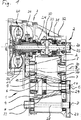
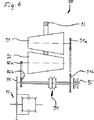
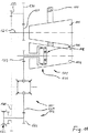
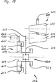
図1から3において図示された変速機は、被同期切替ギア3を経て動力伝達系路に交互に切替えられることができる本質的に2つの変速段階1、2からなる。
この場合、第1の変速段階1は、コーン5を囲む一方で摩擦リング7が動くコーン4と5との間に、隙間6が残るように対向して位置する2つのコーン4、5を有するコーン形の摩擦リング変速機を有する。その結果、このコーン形の摩擦リング変速機がトルクを伝達し、コーン4は、変圧を適用する一方で支柱ベアリング9と10との間で2つのコーン4および5を支える圧力装置8を含む。
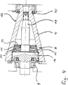
特に図1および4から明らかであるように、コーン4は、動作表面12に加えて、その間で圧力装置8が作動する支柱要素11を有し、圧力装置8は、動作表面12に関して軸方向に締結要素11を移動させることが可能であるので、支柱要素11は、支柱ベアリング9に支持され、そしてさらに、摩擦リング7に対して動作表面12を押圧する。この圧力は、第2のコーン4および補完的な支柱ベアリング10によって対処される。
詳細には、圧力装置8は2つの円板ばね13、14を含み、同様に、2つの圧力要素15、16、および、圧力要素の間に位置する2つのローラ要素17を含む。図2からすぐに明らかであるように、円板ばね13、14および圧力要素15、16は、圧力に関して連続に配置されるので、より正確で再生可能な圧力の設定に導く、関連技術におけるよりもかなり大きい移動作用がトルク変更の場合には圧力要素15に残される。加えて円板ばね13は、動作表面12および/または圧力要素15を有するアセンブリの対応する突起に係合する放射型凹部18、19を有する。このように、円板ばね13は、動作表面12および圧力要素15を有するアセンブリ間にトルクを伝達し、それを通じて圧力要素15は、動作表面15[訳注]*2を備えたアセンブリに関して、トルク装着摺動運動から外される。このことは、同様に結果として生じるトルク依存の圧力のより高い再現性につながる。回転体17は、この例示的な実施例において可変の深さを有する特定の圧力要素15、16の経路で動作する。このように、圧力要素間のトルク依存距離が実行され、圧力要素15、16がトルクの発生によって外周周辺で移動する場合、回転体17は、結果として生じる圧力の高い再現性を保証する。上述の特徴が生じる圧力の再現性を互いに独立して都合よく保証することは、明らかである。
Further advantages, objects and properties of the present invention will be explained based on the description following the attached drawings. There, a typical transmission is illustrated.
The transmission shown in FIGS. 1 to 3 consists essentially of two
In this case, the
As can be seen in particular from FIGS. 1 and 4, the
In detail, the
加えて、ボール17の代わりに、ローラおよび/または圧力要素上に静止して固定された回転体のような他の回転体が使用することができることは、明らかである。さらに、駆動コーン5におけるこのタイプの圧力装置を提供することもまた考えられる。
機械配置の代わりに、しかしながら、別の実施例で、流体力学的または流体静力学的な軸のベアリングのような、トルク依存圧力を実行するために測定されたトルクに基づいて起動する動力付アクチュエータもまた圧力装置に備えることができる。
加えて、圧力要素15、16の移動、および/または、動作表面12および外周周辺に存在する支柱要素11からなる部品の移動、または例えば、支柱ベアリング9、10上の軸方向の力のみが発生しているトルクを決定するために使用されることができることは、明らかである。
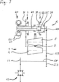
図1から5における例示的な実施例ではさらに、無段コーン摩擦リング変速機2に関して駆動側にトリロクコンバータとして実行される始動クラッチを含む。このため、コーン形の摩擦リング変速機1からなる変速段階は、切替ギア3、および/または、駆動歯車35、および被同期歯車34を経由して直接トリロクコンバータ20のポンプホイール21に接続可能であり、始動は、トリロクコンバータのタービンホイール22を経て、および、差動装置ギア部23を経て実行されることが可能である。後の差動装置ギア部23の差動装置側部24は、第2の差動装置側部25がこの変速段階のアウトプットから使用され、歯車26を経由して結合される一方で、タービンホイール22、および、変速機全体におけるアウトプットピニオン33からなるメイン・アウトプットシャフト28の歯車27にしっかりと結合され、歯車27もまた、コーン形の摩擦リング部分変速機1のアウトプット29と係合している。
In addition, it is clear that instead of the
Instead of a mechanical arrangement, however, in another embodiment a powered actuator that activates based on measured torque to perform a torque dependent pressure, such as a hydrodynamic or hydrostatic shaft bearing Can also be provided in the pressure device.
In addition, only the movement of the
The exemplary embodiment in FIGS. 1 to 5 further includes a starting clutch that is implemented as a tri-lok converter on the drive side with respect to the continuously variable cone
アウトプットピニオン33は、例えば自動車の主差動装置と係合することができる。差動装置ギア部23は、交互にハウジング32上に、またはアウトプット25上に差動装置ギア部23のメインインプットを固定する2つの摩擦クラッチ30、31を備える。このように一見して明らかであるように、アウトプットの回転方向は変更されてもよく、それにより他に何もしなくとも前進用および後退用ギアは実行されることができる。クラッチ30、31が開いている場合、差動装置およびタービンホイール22も惰性で走るので、コーン形の摩擦リング変速機が、アウトプットの連結にかかわらず使用されることができる。
この配置は、始動のためにおよび/または後退用ギアにおいて利点を有し、トリロクコンバータ20の利点が使用されることができる。加えて、前進及び後進ギアは、差動装置23により極めてコンパクトな方法で実行される。さらに、スイッチ3によって、大きなアウトプット損失、および、通常運転におけるスリップを通じた過剰なトルクの増加を引き起こすトリロクコンバータ20の不都合は、タービンホイール22はスイッチ3により短絡され、コーン形の摩擦リング部分変速機1はポンプホイール21を直接経由して駆動されるので、避けることができる。2つの変速段階1および2のアウトプット側の連結は、コーン形の摩擦リング部分変速機1がその変速比に関して、2つの変速段階1および2もまたインプット側にほとんど同期するように2つの変速段階1と2との間の切替手順の前に設定されるのを許容する。残りの同期は、切替ギア3自体によって実行され、トリロクコンバータ20はまた、サポートとして作用することが可能である。
The
This arrangement has advantages for starting and / or in the reverse gear, and the advantages of the
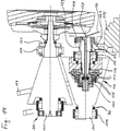
図6に示される変速機配置において、2つの回転し、かつ対向する同軸的に配置されたコーン91、92もまた、コーン91、92のマンテル面の間に残る隙間に沿って移動することができる摩擦リング93を経て互いに機械的に結合されるので、異なる変速比が実行されることができる。この構成では、駆動コーン91およびアウトプットコーン92は、自動車の主差動装置97とピニオン96を経由して交替で係合する主アウトプットシャフト95上へ同期94を経由してスイッチで切替可能である。この配置において、駆動コーン91およびアウトプットコーン92は、同一数の回転方向反転で主アウトプットシャフト軸95に結合される。その結果、回転方向反転は同期94によって直ちに保証される。この配置は、前進及び後進ギアの最小数のアセンブリでの実行を、したがって極めてコスト効率が高い方法で許容する。回転方向反転は、この場合、歯車または回転ベルトの係合により、コーン91、92のうちの1つのみと同期94と間で交互に生じることができるので、第1速ギアまたはオーバードライブもまた、必要に応じてこの配置を通じてコスト的に効率よく表されることができる。駆動の回転方向に依存して、ピニオン91aおよび/または92aおよびホイール91bおよび92bは、ベルト配置を経由して結合、または、直接係合されることができる。加えて、ピニオン96と主差動装置97との間で回転方向を逆転させる歯車を備えることは考えられる。
In the transmission arrangement shown in FIG. 6, two rotating and opposing coaxially arranged
同期は好ましくは休止設定および/または中央位置を備えるので、コーン91、92は惰性で走ることができる。このように、車両が止められる場合でさえ、摩擦リング93および/または他の結合要素は調整されることができる。
図6に示された配置は、コスト効率が高い方法で前進及び後進ギアを提供するため、コーン形の摩擦リング変速機の回転方向反転を特に使用する。これはしたがって、回転方向を逆転させる他の全ての無段変速機に適切である。
加えて、図1から5における配置のように、図6に示された配置は、トルクがコーン形の摩擦リング変速機91、92、93の周辺に伝導されることができるのを使用してアウトプット側と駆動側との両方の上に変速要素を有する。
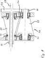
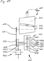
図7に示される動力伝達系路もまた、図1から5における例示的な実施例に記載のように、駆動側上の電力分割器41、および、アウトプット側上の電力分割器42に割り当てられる無段部分変速としてのコーン形の摩擦リング変速機40を備える。この場合、第1速ギア43は、すでに記載されたように、駆動側上で同期した電力分割器41および42を経由してコーン形の摩擦リング変速機40と並行して結合され、摩擦クラッチ44、45を経由して、駆動46とアウトプット47との間で動力伝達系路に交互に切替えられることが可能である。
Since the synchronization preferably comprises a rest setting and / or a central position, the
The arrangement shown in FIG. 6 specifically uses a reversal of the rotational direction of a cone-shaped friction ring transmission to provide forward and reverse gears in a cost-effective manner. This is therefore appropriate for all other continuously variable transmissions that reverse the direction of rotation.
In addition, like the arrangement in FIGS. 1-5, the arrangement shown in FIG. 6 uses that torque can be conducted around the cone-shaped
The power transmission path shown in FIG. 7 is also assigned to a power divider 41 on the drive side and a
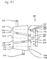
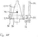
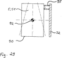
図8において例示的に示された実施例は、特にコーン形の摩擦リング変速機において、連続変速機で両方の側面上での同軸アウトプットを都合よく実行する、駆動およびアウトプットの同軸配置を示す。この配置は、比較的低いハウジング負荷となり、極めてコンパクトに造られ、アウトプットシャフト50は好ましくは ― 特にこの例示的な実施例において ― コーン形の摩擦リング変速機52の駆動コーン51を貫通している。この配置は、また他のタイプの連続変速機において、特に電動モータとの結合において都合がよく、アウトプットシャフトはまた、後者の場合において電動モータの電機子軸を通じて貫通することが可能である。
モータ(図示せず)は、したがって駆動53経由で駆動し、この例示的な実施例において、駆動コーン51は、交替でアウトプットコーン55に作用する。このコーンは、アウトプットシャフト50に設置されたアウトプットホイール57にピニオン56経由で機械的に結合される。
The embodiment illustrated by way of example in FIG. 8 provides a coaxial arrangement of drive and output that advantageously performs coaxial output on both sides in a continuous transmission, particularly in a cone-shaped friction ring transmission. Show. This arrangement results in a relatively low housing load and is extremely compact, with the
A motor (not shown) is therefore driven via
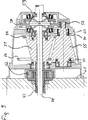
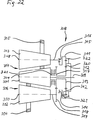
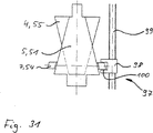
ハウジング60が電動モータのハウジング61に配置される図9に示された変速機は、類似した構造を有する。例示的な実施例においても同様に、電機子軸53は空洞として実行され、アウトプットシャフト50により貫通される。アウトプットピニオン56は、しかしながら、2つの部分の駆動軸50に交替で結合される差動装置59の駆動輪58によって係合する。歯車は、とにかくこの点で提供されなければならないので、この配置は極めてコンパクトに造られる。加えて、この配置はモータと連続変速機との間での補足として、トルク削減のための遊星ギア62を有するので、無段変速機はオーバーロードしない。
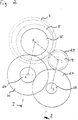
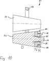
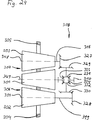
図10に示されるコーン形の摩擦リング配置80は、図7、8および9における配置と結合して特に適用され、極めてコンパクトに、後退用ギアを実行する。この変速機80は、リング83経由で互いに相互作用する2つのコーン81および82を含む。コーン82は、通常のコーン領域(D)に加えて、変速機ハウジング86において交替で取り付けられるように固定され、かつ、その内部はコーン82のコーン形の軸87上で回転する遊星歯車85の周囲を回転するコーンリング84により、この例示的な実施例において実行される反対方向において回転している領域(R)を有する。このように、コーンリング84は、コーン82の残りの部分に対向して回転する。さらに、コーン82は、リング88を含むニュートラル領域(N)を有し、交替でコーン軸87に載置されるので、自由に回転する。
The transmission shown in FIG. 9 in which the
The cone-shaped friction ring arrangement 80 shown in FIG. 10 is particularly applied in combination with the arrangement in FIGS. 7, 8 and 9 and implements the reverse gear in a very compact manner. The transmission 80 includes two
この構成において、摩擦リング83は、コーン82の主領域(D)から、ニュートラルの領域(N)に最初に移動することができ、コーンリング88は、メインコーン82および摩擦リング83によって予め設定される回転にそれ自体を適応させる。摩擦リング83が逆の領域(R)に向かう方向にさらに移動する場合、主領域(D)から離れるので、ニュートラルの領域(N)の回転方向は、後退用リング84の回転方向に適応されることができる。このように、後退用ギアは極めてコンパクトに実現される。
力および/または速度の分割機および/または加算器41または42が最適に切替えられ、変速比が最適に選ばれる場合、コーン形の摩擦リング変速機40および回転軸43が回転しても、アウトプットシャフト47の停止が実行されるので、このタイプの後退用ギア80、および/または、周知の方法で実行される回転方向反転のための配置さえも、図7において例示的に示した実施例では特に都合がよい可能性がある。このように、車両におけるすべての運転状況、すなわち、後進、前進および停止は、移行およびさらなるクラッチなしで実行される。そして、クラッチまたはさらなる変速段階が、満載状態または連続的な負荷動作のような追加的な運転状況に提供されることが確かにまだ可能である。
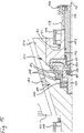
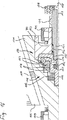
本質的に図1から5における配置と対応していて、繰返しの説明は省かれている図11から18に示される配置において、被同期切替ギア123および/またはコーン形のクラッチ134経由で動力伝達系路に交互に切替えることができる2つの変速経路101、102は、提供される。この場合、第1の変速経路101はまた、コーン105を囲む一方、摩擦リング107が動くコーン104、105の間に隙間6が残るように対向して配置された2つのコーン104、105を有するコーン形の摩擦リング変速機を有する。このコーン形の摩擦リング変速機がトルクを伝達することができるように、コーン104は、可変圧が適用される一方で、本質的に公知のおよび/または上記に記載の方法において2つのコーン104および105を支柱ベアリング109、110の間で支える圧力装置108を備える。このため、圧力装置は、円板ばね120を経て、および、以下に説明されるように、圧力装置108がトルクの機能として、拡大し、かつ、ベアリング109、110に対してそれ自体を対応して支持し、トルクの機能である圧力は適用されて支えられる2つの転動体117およびガイド本体118および119を有する。
In this configuration, the friction ring 83 can initially move from the main region (D) of the
When the force and / or speed divider and / or
In the arrangement shown in FIGS. 11 to 18 which essentially corresponds to the arrangement in FIGS. 1 to 5 and is not described repeatedly, power is transmitted via the
特に図11から明らかであるように、後退用ギアは、その変速経路102が主変速経路から分岐することを用い、駆動輪124を含む。切替ホイール125は、主差動装置115の外付けホイール127に交替で直接係合するピニオン126に被同期切替ギア123経由で連結されることができる中間のホイール130および133を経て駆動される。全体の配置は、極めてコンパクトに造られ、そして、駆動輪124が被同期切替ギア経由で駆動軸121に接続可能であり、かつ、外付けホイール127と直接係合する場合、さらによりコンパクトに実現されることができる。
この後退用ギア102に加えて、配置は連続変速機101によって実行される前進用ギアを含む。前進用ギアは、ピニオン129経由で外付けホイール127に、そして、したがって後退用ギア102に連結され、クラッチ134を経て係合され、かつ、分離される。一見して明らかであるように、部分変速経路101および102の特定の変速要素も、ギアが入っていない状況において惰性で走る。
As is particularly apparent from FIG. 11, the reverse gear includes a
In addition to the
上記で既に示されたように、圧力装置108は、クラッチ134と共に作用する。作動モードは、図15から18に基づいて最もはっきりと参照されることができる。図15および16に示されるように、圧力装置108は、伝達されたトルク機能として拡大することができる。この場合、図15は高いトルク、したがって高圧での配置を示し、図16は低圧での配置を示す。圧力は、トルクの機能として本質的に生成され、支持体119は、対照物150を経て、および、アウトプットシャフト151を経て支柱ベアリング109上にそれ自体を支持する。アウトプットピニオン129もまた、シャフト151上に設置される。加えて、シャフト151は、ニードル軸受152を経て中心にある本体153上放射状に載置される。トルクは、歯154(図18を参照)および155を経てアウトプットコーン104から、アウトプットピニオン129まで伝達される。
圧力装置108において、これらのトルクがコーン117の移動を生じさせるので、圧力は、図15および16において明らかであるように、所望の方法で変化することができる。図15から18まで一見して明らかであるように、2つの本体119および150は、コーン面156、157(図18参照)経由で互いに対して押圧する。最後に、2つのコーン面156、157は、圧力装置108によって閉じられる作動中のクラッチ134を形成する。クラッチ134を開けるため、全体の配置は、その中でピストン159が動き、油圧線160経由でそれに適用される圧力を有するハウジング上に固定されるシリンダ158を有する。ピストン159は、軸のベアリング161および支持体162経由で支持体119に載置される。ピストン159がそれに適用される圧力を有することができる場合、圧力装置108の圧力から、クラッチ134の本体150を外す。クラッチ134が開くと、トルクはもはや伝達されないので、圧力装置108は弛緩し、非常に軽微な圧力のみがクラッチ134を開く、または、それを開いていておくために適用されなければならない。クラッチ134が開いている場合、図18において参照されるように、隙間163はコーン面156、157の間に残る。ピストン159および油圧線160の代わりに、本体119は外され、かつ、クラッチ134は開けられるような他の手段を備えることができることは、明らかである。クラッチ134を回避する一方、全体の変速機のハウジングに支持されることができる本体119を用いたあらゆる手段は、特に適切である。
ピストン159も回転しないので、比較的コスト的に効率よく封止されるという点で、図15から18に示された配置は、特に優れている。
As already indicated above, the
In the
Since the
配置は特に、クラッチを閉じるのに追加的な装置が必要でない利点を有する。加えて、閉鎖力は、圧力装置がいずれにせよこの点に関しては対応して備えられるので、伝達されるトルクの機能であり、かつ、それと共に増大する。
図19および20に示される配置は、直列にそれとともに結合されるコーン形の摩擦リング変速機201、および、後退用ギア202を各々備える。これらの例示的な実施例において、コーン形の摩擦リング変速機201は、本質的に全く同じに造られる、そして、各々は、軸方向に平行して配置され、かつ、互いの方に向いていて、摩擦リング205が、隙間205において置き換え可能であるインプットコーン203およびアウトプットコーン204を有するので、可変変速比は、摩擦リング205の位置の機能として設定される。摩擦リング206は、アウトプットコーン204がアウトプットピニオン207を担持する一方で、これらの例示的な実施例において駆動コーン203を囲む。コーン形の摩擦リング変速機がまた、具体的な実施例に依存して、異なって実行されてもよいことは明らかである。
The arrangement particularly has the advantage that no additional device is required to close the clutch. In addition, the closing force is a function of the torque transmitted and increases with it, since the pressure device is correspondingly provided in this respect anyway.
The arrangements shown in FIGS. 19 and 20 each comprise a cone-shaped
図19の例示的な実施例において、アウトプットピニオン207は、遊星ギア210の太陽歯車209を担持するアセンブリ208と直接係合する。図20に示された配置もまた、アウトプットピニオン207によって駆動される太陽歯車212を有する遊星ギア211からなる。これは、太陽歯車212と共に回転するベルト213およびホイール214経由で実行される。十分に信頼性が高い力伝達が連続的に保証されることができる周知のベルトおよび/またはチェーン配置のすべては、ベルト213として使用されてもよい。
遊星ギア210および211の両方は、一方の側面でそれぞれ特定の太陽歯車209および212と係合し、他方の側面でそれぞれ特定の外付けホイール217および218と係合する遊星歯車215および216をそれぞれ有する。
図19の実施例において、外付けホイール217は、差動装置220の回転マウント219に直接結合される。この構成では、遊星ギア210およびしたがって、後退用ギア202が、そうして差動装置220上に直接位置する。この配置は、動力伝達系路における変速要素の数が最小化されるので、この理由のために極めてコンパクトな構造および極めて高い効率を有することが示された。コンパクトな構造のため、直接差動装置220に配置される後退用ギア202が好都合であることは、本発明の残りの特徴から独立してさえも明らかである。他の点では、このタイプの配置は、最小数の変速要素のみを必要として、したがって、極めて高い効率を有するので、後退用ギアのインプットホイール、および、後退用ギアのアウトプットホイールと直接係合するアウトプットピニオン207が差動装置の回転マウントに直接結合される配置は、コーン形の摩擦リング変速機によって生じる方向反転の理由で現行の自動車エンジンのために都合がよい。
In the exemplary embodiment of FIG. 19, the
Both
In the embodiment of FIG. 19, the
対照的に、図20の実施例において、外付けホイール218は、アウトプットホイール221に結合されて、それとともに回転し、差動装置223の回転マウント222に交替で係合する。これによって生じる方向反転は、ベルト配置213によって補われ、図20の例示的な実施例において後退用ギアは、中間軸224に、および/または周辺に配置される。中間軸224上の配置は、図20の全体の配置がより柔軟にその空間配置を有するように実行されてもよいと図19において提案された差動装置220への直接的な配置において、利点を有する。差動装置への直接的な近接した空間関係が第3のアセンブリによって制限される環境のために、これは特に都合が良い。中間軸224上の後退用ギアの配置が、−特に、それにより生じる回転方向変化のため−本発明の残りの特徴から独立してさえ都合がよいということは、明らかである。後者は、反対の回転方向を有する異種モータと結合してコーン形の摩擦リング変速機が使用されることになっている場合、特にあてはまる。このタイプの場合には、ベルト配置213は省かれる、そして、ピニオン207はカラー214によって係合する。さらにアウトプットコーン204が直接シャフト224上に配置される場合、別々のアウトプットピニオン207およびベルト配置213が完全に省かれるので、都合がよい。
In contrast, in the embodiment of FIG. 20, the
加えて、コーン形の摩擦リング変速機201から生じる駆動が、外付けホイール217および/または218、および/または、太陽歯車209および/または212経由の代わりに後退用ギアの他の変速要素経由で発生することは、当業者にとって一見して明らかである。後退用ギアのアウトプットもまた、外付けホイール217および/または218経由で発生する必要はない。むしろ、太陽歯車および/または他の変速要素はまた、この目的のために使用される。
図19および20で例示的に図示された実施例において「前進」および/または「後退」状態を確実に保つため、遊星歯車215および/または216が取り付けられ、かつ、遊星歯車と共に回転するこれらの例示的な実施例のマウント225および/または226において、一体に固定された変速要素を使用して、固定システムはいずれの場合においても提供される。さらに固定システムは、特定の遊星ギア210および/または211の2つの変速要素の固定を互いに可能して提供される。この場合、図19の例示的な実施例において、太陽歯車209および外付けホイール217は、互いに交互に固定され、図20の例示的な実施例において、遊星歯車216の外付けホイール218および回転マウント226は、互いに交互に固定される。
In addition, the drive resulting from the cone-shaped
19 and 20 in which the
クラッチ、傾斜ブレーキ、および/または、同期のような異なる固定システムは、ハウジングにおよび/または互いに変速要素を固定するために使用されることができる。これらのうちの3つは、例示的な図示された実施例において実施例として示され、そして、具体的な条件に依存して、さらに何にでも交換されることが可能である。
図19の例示的な図示された実施例において、遊星歯車215のマウント225は、遊星歯車215のマウント225において交替で係合する制動ピニオン228を交互に制動することができる電磁ブレーキ227を使用して固定されることができる。したがって、回転方向がこの配置において変更されることになっている場合、ブレーキが起動するので、マウント225が太陽歯車209および外付けホイール217に関して減速される程度において、移動および/またはアウトプットの速度は、それが停止になるまで減少し、そして方向を変更する。
外付けホイール217および太陽歯車209は、ブレーキ229を経て固定され、遊星歯車215もまた、このように外付けホイール217および太陽歯車209に関して固定される。
この状態で、遊星ギア210が極めて低い損失によって動くので、この状況は、好ましくは前進のギアとして選択され、ブレーキ229に対応するブレーキもまた、例えば、マウント225と太陽歯車209および/または外付けホイール217との間に提供されることができることは、一見して明らかである。本質的に遊星ギア210を対応して停止し、全体として回転を許容するため、マウント225に関して遊星歯車215の回転を単に妨げるだけであることはまた、十分である。
Different fastening systems such as clutches, tilt brakes and / or synchronization can be used to secure the transmission elements to the housing and / or to each other. Three of these are shown as examples in the illustrated illustrated embodiment and can be exchanged for anything more, depending on the specific conditions.
In the exemplary illustrated embodiment of FIG. 19, the
The
In this state, the planetary gear 210 moves with very low loss, so this situation is preferably selected as the forward gear, and the brake corresponding to the
図20の例示的な実施例において、交互の固定は、遊星歯車216を担持し、かつ、それらと共に回転し、外付けホイール218と交互に、または、この例示的な実施例においてハウジング232上に固定される固定されたホイール231に関して同期されてもよいマウント226を用いて、同期230を経て実行される。この場合に起こるメカニズムは、図19の例示的な実施例においてすでに説明されたメカニズムと一致するので、マウント226が、外付けホイール218の代わりに太陽歯車212によって同期されてもよいことは明らかである。
図21に示される無段変速機は、インプットコーン301、および、互いに摩擦リング304、305経由で連結され、特定のアウトプットコーン302、303の周りをインプットコーン301へ回る2つのアウトプットコーン302、303を有する。コーン301、302、303の間に残っている隙間に沿って、摩擦リング304、305を移動させることによって、コーン301および302、または301および303によりそれぞれ形成された部分変速機306および307はそれぞれ、連続的に変化することができる。
アウトプット側面上では、2つの部分変速機306、307、および/または、2つのアウトプットコーン302、303は、加重ギア308経由でアウトプットシャフト309へ切替えられる。図21の例示的な図示された実施例において、加重ギア308は、外付けカラー311を有する遊星ギア、遊星歯車312、および、太陽歯車313を備える。外付けカラー311は、コーン303のアウトプットシャフト316に配置されるピニオン315と交替で係合するさらなるカラー314に固定され結合される。太陽歯車313もまた、コーン302のアウトプットシャフト319に配置されるピニオン318と交替で係合するホイール317に固定され結合されて、それと共に回転する。さらに遊星歯車312は、アウトプットシャフト309に結合され、アウトプットシャフト309および遊星歯車312と共に回転するマウント320に取り付けられる。したがって、加重ギア308は、ピニオン315、318および/またはアウトプットコーン302、303の速度が変速比および摩擦リング304、305の位置に依存し、シャフト309の総速度に合計されて提供される。変速比は、摩擦リング304、305の同一の位置、すなわち、2つのアウトプットコーン302、303の同一の速度と共に、遊星歯車312は、マウント320における内在性の回転に関して静止し、単に外付けカラー311および太陽歯車313と共に回転するだけであるように好ましくは選ばれる。このように、連続運転の損失は最小化されることができる。加えて、クラッチ321は、駆動コーン301に直接結合されることができる、または、具体的な実施例に従って速度変換ギア経由で結合されるアウトプットシャフト309を用いて、損失を最小化するために使用されることができるので、無段変速機の利点がいずれにせよ使用されず、このタイプの無段変速機に不必要な損失をさせる特に高速かつ比較的均一の速度において、2つの部分変速機306、307は、回避される。
In the exemplary embodiment of FIG. 20, alternating fixation carries and rotates with
The continuously variable transmission shown in FIG. 21 is connected to an
On the output side, the two
一見して明らかであるように、加重ギア308は、2つのコーン302、303の速度を合計し、そして、また、これらのコーン302、303に適用されるトルクのためのトルクバランスとして使用される。
図22における例示的な図示された実施例は、本質的に図21の例示的な実施例と一致するので、全く同じに作用しているアセンブリもまた、同一の参照番号を有し、同一の機能の繰り返しは省かれる。図21における例示的な実施例の特徴に加えて、図22の例示的な実施例も、遊星歯車312の回転マウント320が外付けカラー311に固定されることができる固定クラッチ322を有し、そしてさらに、マウント320およびアウトプットシャフト309が固定クラッチハウジングに固定されることができるクラッチ323を有する(さらに詳細な図示せず)。第1のクラッチ322は、特定の作動状況における遊星歯車312の内在性の回転を停止させるために使用されるので、遊星歯車312による損失は避けられ、ハウジング320およびシャフト309は、外付けカラー311および太陽歯車313と共に回転する。第2のクラッチ323は、遊星歯車312を適当であるが、それ自身の軸の周りを回転可能である位置に保つために使用される。この配置は、変速機がその外付けカラーおよび太陽歯車313は反対方向に回転することができる、および/または、回転するように設計される変速機との相互作用のために特に提供される。これは例えば、追加的な配置された歯車によって、または、部分変速機306、307のうちの少なくとも1つと加重ギア308との間の変速経路における別々の後退用ギアによってさえ実行されることができる。このタイプの配置において、駆動コーン301が回転する場合であっても、0速度がシャフト309に生じるように、加重ギア308は、2つの部分変速機306、307経由で起動することができる。この状態で、クラッチ323は変速機を固定するために使用されることができる。このタイプの配置において、それから摩擦リング304、305を単に調整すること、および/または、部分変速機306、307を調整することによってアウトプットシャフト309を始動することが可能である。
本質的に図23に示される配置は、図21の配置と一致する。2つの配置の部分変速機306、307は、したがって同一である。加重ギア308のみは、図23における配置で、図21における配置でのそれと異なって実行される。そういうわけで、対応する部品、および、それらの運転モードのより詳細な説明もまた、ここで省略される。
As is apparent at first glance, the
The exemplary illustrated embodiment in FIG. 22 essentially corresponds to the exemplary embodiment of FIG. 21, so that the same acting assemblies also have the same reference numbers and are identical. Repeating functions is omitted. In addition to the features of the exemplary embodiment in FIG. 21, the exemplary embodiment of FIG. 22 also has a fixed clutch 322 in which the
Essentially the arrangement shown in FIG. 23 corresponds to the arrangement of FIG. The two arrangements of
図23に示された無段変速機において、アウトプットシャフト309は、遊星ギアの外付けカラー324に、直接結合されて、それと共に回転する。加えて、遊星歯車312は、遊星歯車312およびホイール326と共に回転することができるマウント325に取り付けられ、ホイール326は、コーン303のアウトプットシャフト306上のピニオン315と係合している。対照的に、太陽歯車313は、図21および22の例示的な実施例に記載のように、コーン2のアウトプットシャフト319上のピニオン318と係合するホイール317に結合される。
したがって図23に示されるギア308もまた、加重ギアとして作用して、2つの部分変速機306、307の速度を加える、および/または、減ずる。
また、図24に示される配置は、その部分変速機306、307に関して、図21から23に示される配置と本質的に一致する。本質的に、ギア308のみは異なって実行される。この場合、加重ギア308は、それぞれがアウトプットシャフト316および319に配置されるコーン303および302の傘歯車327および328経由でそれぞれ駆動される。このため、傘歯車327および328は、それぞれ自身の軸のまわりを回転する差動装置の、固定された傘歯車331および332に交替で結合される傘歯車329および330とそれぞれ係合する。図24におけるギアのアウトプットは、それぞれ差動装置の傘歯車331および332と交替で係合する差動装置の回転傘歯車333および334の軸受に結合される歯車310を経て発生する。一見して明らかであるように、加重ギアもまた、この配置により備えられる。
In the continuously variable transmission shown in FIG. 23, the
Accordingly, the
Further, the arrangement shown in FIG. 24 essentially corresponds to the arrangement shown in FIGS. 21 to 23 with respect to the
図25における例示的な実施例の基本的な構造は、図24における例示的な実施例と一致するので、ここで、加重ギア308もまた、アウトプットホイール336を用いて傘歯車337経由でアウトプットシャフト309を駆動する差動装置335により本質的に形成される。加えて、アウトプットホイール336は、駆動コーン301に被同期クラッチ339を経て交替で接続可能である傘歯車338と係合するので、2つの部分変速機306、307は必要に応じて回避されることができる。さらに、この配置において、アウトプットコーン302、303のアウトプットシャフト316、319はそれぞれ、被同期クラッチ340および341経由で、固定された軸の周りを回る差動装置の傘歯車に結合される傘歯車346および347とそれぞれ交替で係合する傘歯車342、343、および、344、345に交互にスイッチで切り替え可能である。部分変速機306、307の活発な回転方向は、したがってクラッチ340および/または341によって、容易に変更されることができるので、図25における変速機が極めて用途が広い変速機挙動を有する。
示されたコーン形の摩擦リング変速機306、307の代わりに、他の無段変速機もまた、本発明によるこのタイプの無段変速機のための部分変速機として都合よく使用されることができることは、明らかである。図21から25において一見して明らかであるように、部分変速機306、307は、互いに各々並列に配置され、すべて図面の平面に位置する特定のコーン体軸348、349、350により定義される部分変速面を有する。このように、変速機は極めて平らに造られ、それらは例えば、荷重表面の下で提供されるので、トラックおよび/または小さいトラックに用いられるために特に適切である。より高いトルクで2つの部分変速機を使用することにより良い効率で作動する本発明よる変速機は、現代のディーゼルエンジンによって適用されるので、極めて高圧力は、2つの部分変速機を使用することにより避けることができるため、それは、いっそう適切である。
The basic structure of the exemplary embodiment in FIG. 25 is consistent with the exemplary embodiment in FIG. 24, so here the
Instead of the cone-shaped
すでに、図21から24における記載および例示的な実施例に基づいて示され、図25における例示的な実施例に基づいて例示的な用途のために説明されたように、変速機の全体の特徴は、部分変速機306、307が加重ギア308に作用する回転方向の選択によって、かなり影響される可能性がある。特に、このタイプの後退用ギアおよび/または回転方向を変更する部分変速機は、都合がよい。この点に関する変形例は、上述の部分変速機80の例証として図10において説明された。
図21から25に示された変速機において、力の流動もまた、後退として選ばれることができるので、アウトプット要素309、310はインプット要素として使用され、インプットコーン301はアウトプットコーンとして使用されることは、明らかである。
図14から17までと同様に図1、4、8、および9から推定されるように、その中で示された無段変速機は、封止70によりそれらの軸受の方向に各々封止される(実施例としてのみ確認される)。関連技術から分かるように、別個の流体容器はコーンと結合要素が位置付けられている部分へ位置付けられる。例示的な本実施例において、約10から30モルパーセントのポリジメチル・シロキサンのメチレン基が好ましくはフェニル基と置換され、25°Cの粘性が好ましくはほぼ200mm2/秒である「シリコーンオイル」は、流体として好ましくは使用される。しかしながら、その物理的および化学的なパラメータの温度依存が、鉱油の温度依存に関して安定し、および/または、温度に依存する圧縮変化度および/または温度に依存する粘性変化度に関して、鉱油の変化度とシリコーンオイルの変化度との間に位置する他のいかなる流体も使用されることができる。
例示的な流体および/または上記の液体の温度依存は、一例として図26において対数関数的な形状で示され、白線89aは、鉱油を表し、白線89bは、シリコーンオイルを表している。これらの流体は、流体によって架橋された隙間が、コーン4、5;51、55、81、82、91、92、104、105、203、204、301、302、303と、結合要素7;54、83、93、107、205、304、305との間で、形成されてもよいという運転条件を保証する。この隙間の存在は、電気電圧測定を通じて金属部品において検出され、例えば、この隙間が数回転した後のみに形成される、すなわち、流体が分配される場合、実験的に決定されてきたので、隙間の寸法に関して、圧縮性および粘性が最適に選ばれることになっている。この場合、対応する隙間が運転条件において維持されるというように、支柱および/または圧力装置は必要な大きさにされる。
異なる動作経路のため、およびしたがって、コーン4、5;51、55、81、82、91、92、104、105、203、204、301、302、303の異なる半径の均一の表面圧を保証するため、軸方向に異なるように、各々のコーンの動作表面12は好ましくは実行される。現在の例示的な実施例において、これは異なる幅(図示せず)の溝で実行される。あるいは、軸方向に異なる表面粗さ測定器または類似した何かが、備えられてもよい。
The overall characteristics of the transmission, as already shown based on the description and exemplary embodiment in FIGS. 21 to 24 and described for the exemplary application based on the exemplary embodiment in FIG. Can be significantly affected by the choice of rotational direction in which the
In the transmission shown in FIGS. 21 to 25, the force flow can also be chosen as a reverse, so that the
As estimated from FIGS. 1, 4, 8, and 9 as well as FIGS. 14-17, the continuously variable transmissions shown therein are each sealed in the direction of their bearings by seals 70. (Confirmed only as an example). As can be seen from the related art, a separate fluid container is positioned where the cone and coupling element are positioned. In this illustrative example, a “silicone oil” in which about 10 to 30 mole percent of the polydimethylsiloxane methylene groups are preferably replaced with phenyl groups and the viscosity at 25 ° C. is preferably approximately 200 mm 2 / sec. Are preferably used as fluids. However, the temperature dependence of its physical and chemical parameters is stable with respect to the temperature dependence of the mineral oil and / or the degree of change of the mineral oil with respect to the temperature dependence of the compression change and / or the temperature dependence of the viscosity change. Any other fluid located between and the degree of change in silicone oil can be used.
The temperature dependence of an exemplary fluid and / or the above liquid is shown by way of example in a logarithmic shape in FIG. 26, with
Ensures uniform surface pressures of different radii for different operating paths and thus of
摩擦リング7;54、83、93、107、205、304、305の表面は、摩擦リング71に基づいて図27における例示的な用途のために示されたように、コーン4、5;51、55、81、82、91、92、104、105、203、204、301、302、303と、摩擦リング7;54、83、93、107、205、304、305との間で残っている隙間において液体の剪断力に影響するために好ましくは溝を備えている。摩擦リング71は、コーン4、5;51、55、81、82、91、92、104、105、203、204、301、302、303の表面と相互作用する摩擦リング7;54に基づいて説明されたように、2つの回転表面72、73をそれぞれ有する。この場合、表面72、73は異なる表面設計を有する。例えば、台形の力板74(図27b参照)は特に都合が良い。なぜなら、リング71の残りの材料上に、特によくそれ自身を支持するからである。累積的におよび/または代替的に、直径に沿って対向する表面における内部のフランジが避けられるような、丸い溝の吸気口(図27bおよび27c参照)は、提供される。丸い溝吸気口75はまた、油膜および/または表面圧の分配のために都合がよいようである。丸い溝の底面76(図27b、27cおよび27d参照)は、対照的に、負荷の下において溝底面の切欠き効果を避けることができる。本質的に立方形の力板77(図27c参照)もまた、備えることができる。図27dおよび27eに示されたように、丸い外部の断面形状79を有する力板78もまた、使用される。
このタイプの溝は、具体的な実施例に従い、摩擦リングの表面に全く同じに、および/または、両方のコーンで異なって提供される。特に、軸方向における溝および/または力板の分配は、表面上において変化することができる。このように、例えば、表面圧および/または表面圧分配は変化、および/または、コーンに沿ってさえも最適に設定されてもよく、および/または、オイル膜厚は適応することができる。特に溝横断面は、この場合における特定の変速要素の接点領域からのオイルの排液量を主に決定する。
The surfaces of the friction rings 7; 54, 83, 93, 107, 205, 304, 305 are based on the friction rings 71, as shown for the exemplary application in FIG. 55, 81, 82, 91, 92, 104, 105, 203, 204, 301, 302, 303 and the
This type of groove is provided exactly the same on the surface of the friction ring and / or differently on both cones, according to a specific embodiment. In particular, the distribution of grooves and / or force plates in the axial direction can vary on the surface. Thus, for example, the surface pressure and / or surface pressure distribution may vary and / or be optimally set even along the cone and / or the oil film thickness may be adapted. In particular, the groove cross-section mainly determines the amount of oil drained from the contact area of the particular transmission element in this case.
加えて、摩擦リングは、好ましくは冠部を持つ横断面を有するので、隙間の存在にもかかわらず、大きい可能な接点領域はヘルツ応力を経て実行される。
摩擦リング7、54、83、93、107、205、304、305それ自体(例示的な用途にのみのため、図28から31において7、54と番号をつけられた)は、図28に示されるように、作動ブリッジ91がその上で動作し、かつ、軸92の周りを回転可能であるよう取り付けられた保持器90により、現在の例示的な実施例において周知の方法で保持される。しかしながら関連技術に反して、作動ブリッジ91は、保持器90の角度が変わる場合、自由に動かず、むしろ、アクチュエータ93経由で、ハウジング32に載置された主軸94において明らかに制御されるので、それは回転可能である。この場合、十分な遊びは、アクチュエータ93と作動ブリッジ91との間で提供されるので、アクチュエータ93の移動は最初に、保持器90の角度を変更させ、その後、リング7、54、83、93、107、205、304、305は回転軸において対応して移動する、そして、アクチュエータ93の移動が続く。
それ自体の力によるリング7、54、83、93、107、205、304、305の調整の角度が重大な意味を持つので、保持器90の角度に関するプレテンションは、ハウジング32と保持器90との間のばね95によって、この例示的な実施例において実行される。その結果、作動ブリッジ91とアクチュエータ93との間の遊びは、図29に概略的に示されているように、意図的でなく保持器90の角度を変更させない。
加えて、作動ブリッジ91が動いてもよいハウジング32上に(図30において例示的な用途のために示される)端部ストッパ96があり、これらの端部ストッパは、リング7、54、83、93、107、205、304、305が回転軸に関してコーン体軸に並列に整列配置され、したがって、もはや移動しないように置かれている。このように、リングの位置決め装置が故障した場合、変速機の完全な破壊は防ぐことができる。作動ブリッジ91の対応する位置を表示するセンサもまた、この点において備えられてもよい。
代替調整可能性97は、図31に示され、この実施例バリエーションは、極めてコスト的に効率よく造られる。この実施例バリエーションにおいて、リング7、54、83、93、107、205、304、305は保持装置98によって一方の側面のみに導かれる。この保持装置は、アプローチ側に備えられるので、選択された図において、最初に保持装置98から始まるリング7、54、83、93、107、205、304、305は最初にコーン4、5;51、55、81、82、91、92、104、105、203、204、301、302、303の間の隙間を通過し、そしてそれが再び保持装置98に達する前にコーン5;51、81、91、105、203、302、303の周りを回転する。保持装置98は、主軸99に載置され、かつ、十分な遊びでリングを囲むので、移動する動きを実行し、それ自体の力により保持装置98の動きに続くコーン体軸により形成される平面から、その回転軸の角度を移動させることができる。保持装置98の遊びの変形例として、主軸として実行されるアクチュエータ99に関して図31の図面の平面における回転自由度を備えることができ、かつ、本質的に遊びなしでリングを導く。
In addition, since the friction ring preferably has a cross section with a crown, a large possible contact area is carried out through Hertzian stresses despite the presence of gaps.
Friction rings 7, 54, 83, 93, 107, 205, 304, 305 themselves (numbered 7, 54 in FIGS. 28-31 for exemplary purposes only) are shown in FIG. As shown, the actuating
Since the angle of adjustment of the
In addition, there are end stops 96 (shown for exemplary use in FIG. 30) on the
An
リング7、54、83、93、107、205、304、305が、回転軸に対して垂直なトルクを有して実行される場合、休止100上に一方の側のリング7、54、83、93、107、205、304、305を導くのみである保持装置は、備えることができ、このトルクを妨げ、および、 ― 所望の移動に従い ― リングから離れるように移動するので、それ自体の力によりコーン体軸によって形成される平面から、その回転軸の回転運動を完成し、再び適切にそれを整列配置し、またはリングの回転軸がその方へ動くように旋回する誘導装置に達するまで、移動し始める。その結果、それは誘導装置がもはや続かなくなるまで、誘導装置から離れて移動し、それが再び誘導装置に達するまで、再びそれ自体のトルクでその回転軸の方へ旋回して戻る。
後者の配置は、リング7、54、83、93、107、205、304、305の特に大きい量の遊びを許容するので、それは摩擦損失が最小化されるように非常に独立して、かつ、自動安定的に移動することができる。
If the
The latter arrangement allows a particularly large amount of play of the
Claims (2)
少なくとも1つの前記コーンが、前記コーンの外周方向に沿う溝を有し、2つの溝の間の距離が前記コーンの表面の軸方向に変化し、少なくとも1つの前記コーンの表面のうち摩擦リングと接触する部分が異なると、動作経路が異なり、その結果として変速比が異なることを特徴とするコーン形摩擦リング変速機。A rotary transmission having at least two cones capable of transmitting torque by friction and a friction ring connecting the cones;
At least one of the cones has a groove along an outer circumferential direction of the cone, and a distance between the two grooves varies in an axial direction of the surface of the cone; A cone-type friction ring transmission characterized in that when the contacting parts are different, the operation path is different, and as a result, the transmission ratio is different.
前記摩擦リングは、溝を有する少なくとも1つの動作表面を有することを特徴とするコーン形摩擦リング変速機。The cone-shaped friction ring transmission according to claim 1,
The cone-shaped friction ring transmission, wherein the friction ring has at least one working surface with a groove.
Applications Claiming Priority (13)
| Application Number | Priority Date | Filing Date | Title |
|---|---|---|---|
| DE10245897.9 | 2002-09-30 | ||
| DE10245897 | 2002-09-30 | ||
| DE10246655.6 | 2002-10-07 | ||
| DE10246655 | 2002-10-07 | ||
| DE10303891.4 | 2003-01-30 | ||
| DE10303891A DE10303891A1 (en) | 2002-09-30 | 2003-01-30 | Gear system, e.g. for power transmission, comprises thruster unit pressing, with variable force, with running surface of one conical element against friction ring |
| DE10303896A DE10303896A1 (en) | 2002-09-30 | 2003-01-30 | Transmission unit has torque adjustment drive fed with energy from source turning gear train of gear unit. |
| DE10303896.5 | 2003-01-30 | ||
| DE10304094.3 | 2003-01-31 | ||
| DE10304094 | 2003-01-31 | ||
| DE10323109.9 | 2003-05-20 | ||
| DE10323109 | 2003-05-20 | ||
| PCT/DE2003/003254 WO2004031615A2 (en) | 2002-09-30 | 2003-09-29 | Epicyclic gear |
Publications (2)
| Publication Number | Publication Date |
|---|---|
| JP2006501426A JP2006501426A (en) | 2006-01-12 |
| JP4988198B2 true JP4988198B2 (en) | 2012-08-01 |
Family
ID=52433687
Family Applications (1)
| Application Number | Title | Priority Date | Filing Date |
|---|---|---|---|
| JP2005500019A Expired - Fee Related JP4988198B2 (en) | 2002-09-30 | 2003-09-29 | Rotating transmission |
Country Status (7)
| Country | Link |
|---|---|
| US (2) | US7559868B2 (en) |
| EP (1) | EP1546578B1 (en) |
| JP (1) | JP4988198B2 (en) |
| AU (1) | AU2003299146A1 (en) |
| BR (1) | BRPI0307387B1 (en) |
| ES (1) | ES2528176T3 (en) |
| WO (1) | WO2004031615A2 (en) |
Families Citing this family (15)
| Publication number | Priority date | Publication date | Assignee | Title |
|---|---|---|---|---|
| DE102007002581A1 (en) * | 2006-09-22 | 2008-04-03 | Rohs, Ulrich, Dr. Ing. | Bevel friction ring gear has axial variation of friction surface having radius in excess of 0.1 mm, in at least two convex regions, and a radius in excess of 0.01 mm in at least two concave regions |
| WO2008104142A1 (en) * | 2007-02-26 | 2008-09-04 | GIF Gesellschaft für Industrieforschung mbH | Drive arrangement with a continuously variable sub-gear mechanism |
| DE112008003116A5 (en) * | 2007-11-27 | 2010-08-19 | Rohs, Ulrich, Dr. Ing. | Bevel friction ring gear and method for assembling or producing a conical friction ring gear |
| KR101181748B1 (en) * | 2010-03-18 | 2012-09-11 | 현대 파워텍 주식회사 | Cone-Ring Type Continuous Variable Transmission |
| US8574110B2 (en) * | 2010-08-02 | 2013-11-05 | Ford Global Technologies, Llc | Transmission producing stepless variable speed ratios |
| JP2012062935A (en) * | 2010-09-15 | 2012-03-29 | Ud Trucks Corp | Continuously variable transmission |
| DE102011013070A1 (en) * | 2011-03-04 | 2012-09-06 | Ulrich Rohs | Conical friction ring gearbox has friction ring with circular friction ring outer edge between friction ring outer surface and outer friction surface, where radius of friction ring outer edge is preset times of friction ring width |
| KR101272935B1 (en) * | 2012-03-12 | 2013-06-11 | 현대자동차주식회사 | Automated manual transmission for vehicle |
| KR101360431B1 (en) * | 2012-09-04 | 2014-02-11 | 현대 파워텍 주식회사 | Stepless transmission |
| KR20150084935A (en) * | 2013-01-18 | 2015-07-22 | 쟈트코 가부시키가이샤 | Multi-disk transmission |
| US10221927B2 (en) | 2014-08-14 | 2019-03-05 | Ford Global Technologies, Llc | Continuously variable transmission with overdrive |
| DE102014013468A1 (en) | 2014-09-17 | 2016-03-17 | Ulrich Rohs | Bevel friction ring gear and method for operating a conical friction ring gear |
| DE102015200798B3 (en) | 2015-01-20 | 2016-06-16 | Schaeffler Technologies AG & Co. KG | Gear arrangement for an electric motor of a vehicle and vehicle with the gear assembly |
| US9970521B1 (en) | 2016-02-26 | 2018-05-15 | Rodney J. Cook and successors in trust | Infinitely variable transmission |
| US11772743B2 (en) * | 2022-02-18 | 2023-10-03 | Joseph Francis Keenan | System and method for bicycle transmission |
Family Cites Families (97)
| Publication number | Priority date | Publication date | Assignee | Title |
|---|---|---|---|---|
| US299231A (en) | 1884-05-27 | Device for transmitting motion | ||
| US1709346A (en) * | 1929-04-16 | garrard | ||
| US1069182A (en) | 1912-12-13 | 1913-08-05 | Remy Brothers Company | Differential speed-changing mechanism. |
| US1637664A (en) | 1924-02-02 | 1927-08-02 | Stoeckicht Wilhelm | Change-speed friction gearing |
| FR615659A (en) | 1926-05-05 | 1927-01-13 | Continuous and automatic gear change | |
| GB298676A (en) | 1927-07-15 | 1928-10-15 | Charles George Garrard | Improvements in and relating to variable speed gearing |
| US1868676A (en) | 1929-05-03 | 1932-07-26 | Stoeckicht Wilhelm | Friction roller gearing |
| GB343225A (en) | 1929-12-09 | 1931-02-19 | Herbert Reed Hall | Improvements in and relating to speed gears of the infinitely variable type |
| US2073157A (en) * | 1936-04-20 | 1937-03-09 | Rex Hide Inc | Wiper blade fastener |
| DE745147C (en) | 1939-04-28 | 1944-02-28 | Aeg | Gearbox with locking clutch |
| US2545152A (en) | 1947-07-16 | 1951-03-13 | Ebauches Sa | Infinitely variable speed gear |
| US2583790A (en) | 1948-11-10 | 1952-01-29 | Westinghouse Electric Corp | Frictional gear mechanism |
| US2743621A (en) * | 1949-11-02 | 1956-05-01 | Beier Josef | Infinitely variable friction wheel gears |
| CH290407A (en) | 1950-09-20 | 1953-04-30 | Ag Dabo | Mechanical stepless change gear. |
| US3048046A (en) * | 1960-04-11 | 1962-08-07 | Algar H Cosby | Power transmission for variable speed and torque |
| US3026736A (en) | 1960-12-06 | 1962-03-27 | Friedrich Cavallo Getriebe Und | Ball transmission unit |
| FR1299074A (en) * | 1961-06-08 | 1962-07-20 | G Ab | Multiple friction variable speed drive |
| US3375733A (en) | 1966-01-10 | 1968-04-02 | Deere & Co | Combined variable speed and planetary drive |
| FR1523231A (en) | 1967-02-14 | 1968-05-03 | Devices using friction drive between two smooth surfaces in a liquid medium | |
| USRE27211E (en) * | 1969-10-15 | 1971-11-02 | Friction drive fluid | |
| US3677109A (en) | 1971-01-14 | 1972-07-18 | Gates Rubber Co | Continuously variable friction gear |
| DE2336337A1 (en) | 1973-07-17 | 1975-01-30 | Neuweg Fertigung Gmbh | HYDRAULICALLY SUPPORTED MECHANICAL PRESSURE CONTROLLER FOR CONTINUOUSLY ADJUSTABLE ROLLING GEAR |
| CA1070664A (en) | 1974-09-16 | 1980-01-29 | Marvin F. Smith (Jr.) | Viscosity index additives for lubricating oils |
| DE2621682A1 (en) * | 1976-05-15 | 1977-11-24 | Zahnradfabrik Friedrichshafen | CONTINUOUSLY ADJUSTABLE TAPERED DISC CONVERSION GEAR |
| GB1499019A (en) | 1976-08-16 | 1978-01-25 | United Lubricants Ltd | Liquid coolant composition |
| US4238976A (en) | 1978-10-19 | 1980-12-16 | Vadetec Corporation | Infinitely variable power transmission and system |
| US4382188A (en) | 1981-02-17 | 1983-05-03 | Lockheed Corporation | Dual-range drive configurations for synchronous and induction generators |
| US4449415A (en) | 1981-09-23 | 1984-05-22 | Dow Corning Corporation | Traction fluid and traction drive system containing said fluid |
| EP0105370A4 (en) | 1982-03-15 | 1984-04-27 | Caterpillar Tractor Co | Gear train having an internal gear mechanism. |
| JPS5965659A (en) | 1982-10-04 | 1984-04-13 | Nissan Motor Co Ltd | Power transmission device |
| DE3241789C2 (en) | 1982-11-11 | 1985-08-08 | Ford-Werke AG, 5000 Köln | Gear unit for vehicles, in particular for front-wheel drive vehicles |
| JPS60116959A (en) | 1983-11-28 | 1985-06-24 | Toyota Central Res & Dev Lab Inc | Continuously variable transmission for vehicles |
| US4577523A (en) * | 1983-11-28 | 1986-03-25 | Dow Corning Corporation | Silicone traction fluids |
| GB8412855D0 (en) | 1984-05-19 | 1984-06-27 | Stidworthy F M | Self-regulating transmission |
| GB2180020A (en) | 1985-09-03 | 1987-03-18 | Ford Motor Co | Continuously variable transmission combining chain and V-belt drives with hydrokinetic torque converter |
| JPS62184270A (en) * | 1986-02-07 | 1987-08-12 | Toyota Central Res & Dev Lab Inc | Belt driven type non-stage transmission |
| SU1557395A2 (en) | 1986-07-14 | 1990-04-15 | И.Г.Мухин, А И.Мухин, Н„И.Кузевич, 0,Н.Мухина и В.В.Кузевич | Variable-speed drive |
| JPH01105057A (en) | 1987-10-14 | 1989-04-21 | Kubota Ltd | Friction type continuously variable transmission |
| DE3835052A1 (en) | 1987-10-21 | 1989-05-03 | Barmag Barmer Maschf | Frictional element gearing |
| EP0321621B1 (en) | 1987-12-23 | 1993-03-24 | Honda Giken Kogyo Kabushiki Kaisha | Continuously variable automotive transmission |
| US4955852A (en) | 1988-07-07 | 1990-09-11 | Toyota Jidosha Kabushiki Kaisha | Planetary gear mechanism having means for accurate alignment of sun gear |
| JPH0272262A (en) * | 1988-09-07 | 1990-03-12 | Toyota Motor Corp | Pulley for belt type continuously variable transmission |
| JPH06100257B2 (en) | 1989-09-04 | 1994-12-12 | バンドー化学株式会社 | Continuously variable transmission |
| US5073157A (en) | 1990-02-20 | 1991-12-17 | Power Engineering & Manufacturing, Ltd. | Mechanically variable transmission |
| US5069078A (en) | 1990-07-30 | 1991-12-03 | Fairbanks Everitt E | Transmission mechanism |
| BE1004806A3 (en) | 1990-11-22 | 1993-02-02 | Volvo Car Sint Truiden Nv | Device for controlling a continuously variable transmission for motor vehicles. |
| EP0507329A3 (en) | 1991-04-05 | 1993-10-27 | Mazda Motor | Power transmission device for vehicle |
| DE4202200A1 (en) | 1992-01-28 | 1993-07-29 | Fichtel & Sachs Ag | Friction clutch actuator for IC engine powered motor vehicle - removes integral component of positioning control signal when sum and integral component are of opposite sign |
| DE4204200A1 (en) | 1992-02-13 | 1993-08-19 | Daimler Benz Ag | Liq. useful as heat transfer and insulating media - comprises mixt. of poly-alpha-olefin(s) and/or isoparaffin(s) with poly:di:methyl:siloxane(s) and/or poly:alkyl -/poly:aryl:siloxane(s) |
| JPH05340456A (en) | 1992-06-08 | 1993-12-21 | Nippon Seiko Kk | Power transmission device |
| RU2079017C1 (en) | 1992-06-18 | 1997-05-10 | Новосибирский государственный технический университет | Friction clutch |
| JPH06174036A (en) | 1992-11-30 | 1994-06-21 | Isuzu Motors Ltd | Toroidal type continuously variable transmission |
| JP3569537B2 (en) * | 1993-09-30 | 2004-09-22 | Ntn株式会社 | Friction transmission mechanism |
| IN189939B (en) | 1993-12-20 | 2003-05-17 | Torotrak Dev Ltd | |
| DE4445017A1 (en) | 1994-03-12 | 1995-09-14 | Kupplungstechnik Gmbh | Limited torque clutch for relief of overload |
| EP1114951A3 (en) | 1995-02-27 | 2002-02-13 | Isuzu Motors Limited | Toroidal continuous variable transmission |
| DE19607812A1 (en) | 1995-03-21 | 1996-09-26 | Luk Getriebe Systeme Gmbh | Gearing unit with radially variable rotors |
| DE19525068A1 (en) | 1995-07-10 | 1997-01-16 | Wacker Chemie Gmbh | Coating compositions based on powders containing water-redispersible, water-soluble polymer and organosilicon compound |
| US5984820A (en) * | 1995-10-26 | 1999-11-16 | Getrag Innovations Gmbh | Motor vehicle transmission having a continuously variable transmission ratio |
| FR2741128A1 (en) | 1995-11-09 | 1997-05-16 | Crasset Dominique | IMPROVEMENTS IN SYSTEM ACTUATION DEVICES SUCH AS CLUTCHES OR GEARBOXES |
| DE19542726B4 (en) | 1995-11-16 | 2006-02-16 | Rohs, Ulrich, Dr.-Ing. | bevel friction ring gearing |
| JPH10205600A (en) * | 1997-01-21 | 1998-08-04 | Nissan Motor Co Ltd | Rolling element structure for toroidal type continuously variable transmission, method for forming surface film of rolling element structure for toroidal type continuously variable transmission, and lubricating composition for toroidal type continuously variable transmission |
| DE19717290A1 (en) | 1997-04-24 | 1998-10-29 | Claas Usines France | Torque measuring system, transmitting by line drive protected by overload, for coupling machines |
| JP4128636B2 (en) * | 1997-05-19 | 2008-07-30 | ウルリッヒ・ロース | Conical friction ring transmission and method for friction ring control of conical friction ring transmission |
| US5924953A (en) | 1997-05-21 | 1999-07-20 | Rohs; Ulrich | Friction cone gearing |
| DE19909347B4 (en) | 1998-03-10 | 2012-03-29 | Schaeffler Technologies Gmbh & Co. Kg | transmission |
| JP3956475B2 (en) | 1998-03-13 | 2007-08-08 | 日本精工株式会社 | Toroidal continuously variable transmission |
| ES2166589T3 (en) * | 1998-04-24 | 2002-04-16 | Doornes Transmissie Bv | DRIVE ASSEMBLY FOR VEHICLE. |
| DE19837368A1 (en) | 1998-08-18 | 2000-02-24 | Ulrich Rohs | Bevel friction ring gear and method for controlling the transmission ratio in a bevel gear |
| JP2000120822A (en) | 1998-10-21 | 2000-04-28 | Nsk Ltd | Continuously variable transmission |
| JP2000130531A (en) | 1998-10-29 | 2000-05-12 | Isuzu Motors Ltd | Continuously variable transmission |
| JP4048625B2 (en) | 1998-12-15 | 2008-02-20 | 日産自動車株式会社 | Shift control device for continuously variable transmission with infinite gear ratio |
| JP3855142B2 (en) | 1999-04-08 | 2006-12-06 | 允彦 丹原 | Continuously variable transmission |
| JP3736191B2 (en) * | 1999-04-08 | 2006-01-18 | トヨタ自動車株式会社 | Power transmission mechanism |
| US6056661A (en) * | 1999-06-14 | 2000-05-02 | General Motors Corporation | Multi-range transmission with input split planetary gear set and continuously variable transmission unit |
| US6139465A (en) | 1999-06-16 | 2000-10-31 | Holliday; Sander | Infinite speed transmission |
| FR2796693B1 (en) | 1999-07-21 | 2001-11-16 | Renault | TRANSVERSE DRIVE GROUP WITH VARIABLE DRIVE AND EPICYCLOIDAL TRAIN |
| KR100361929B1 (en) | 1999-09-10 | 2002-11-22 | 남성훈 | Speed change friction apparatus |
| JP2001088585A (en) * | 1999-09-24 | 2001-04-03 | Mitsubishi Motors Corp | Hybrid vehicle control device |
| FR2800826B1 (en) | 1999-11-10 | 2001-12-21 | Renault | TRANSVERSE VEHICLE DRIVE GROUP COMPRISING A VARIATOR AND AN EPICYCLIADAL TRAIN |
| US6379275B1 (en) * | 1999-11-18 | 2002-04-30 | The Gates Corporation | Continuously variable transmission pulley |
| JP3630297B2 (en) | 2000-03-23 | 2005-03-16 | 日産自動車株式会社 | Toroidal continuously variable transmission for automobiles |
| JP2001343056A (en) * | 2000-06-01 | 2001-12-14 | Bando Chem Ind Ltd | Transmission |
| DE20020562U1 (en) | 2000-06-27 | 2001-05-03 | Eichholz, Werner, 45149 Essen | Variable transmission, mechanical stepless speed adjustment for drives of all kinds |
| JP2002048213A (en) * | 2000-08-01 | 2002-02-15 | Toyota Motor Corp | Transmission with continuously variable transmission |
| JP3633484B2 (en) * | 2001-01-22 | 2005-03-30 | トヨタ自動車株式会社 | Control device for vehicle having internal combustion engine and continuously variable transmission |
| JP4378898B2 (en) | 2001-05-08 | 2009-12-09 | 日本精工株式会社 | Toroidal continuously variable transmission and continuously variable transmission |
| JP3758546B2 (en) | 2001-10-05 | 2006-03-22 | 日本精工株式会社 | Continuously variable transmission |
| US6623399B2 (en) * | 2001-12-28 | 2003-09-23 | Dow Corning Corporation | Traction fluids |
| CN1578890B (en) * | 2002-09-30 | 2010-05-26 | 乌尔里克·罗斯 | Transmission mechanism |
| ATE420306T1 (en) | 2002-10-22 | 2009-01-15 | Luk Lamellen & Kupplungsbau | POWER-SPLIT TRANSMISSION WITH CONTINUOUSLY ADJUSTABLE RATIO |
| CN1606669B (en) * | 2003-01-06 | 2011-01-05 | 乌尔里克·罗斯 | Pressing device and conical friction transmission mechanism and operation method of conical friction transmission mechanism |
| JP2006513376A (en) * | 2003-01-09 | 2006-04-20 | ロース,ウルリヒ | Continuously variable transmission |
| US6908406B2 (en) | 2003-03-05 | 2005-06-21 | Mark Albert Overbay | Continuously variable transmission with elastomeric meshing interface |
| DE102004003691B4 (en) * | 2004-01-24 | 2018-10-31 | Zf Friedrichshafen Ag | Cone Ring Transmission |
| US7048667B2 (en) * | 2004-02-09 | 2006-05-23 | Ford Global Technologies, Llc | Power split transaxle for producing stepless reverse, forward and geared neutral speed ratios |
| TWM261145U (en) * | 2004-07-30 | 2005-04-11 | Hsiao-Wei Nien | Bracket structure |
-
2003
- 2003-09-29 EP EP03756445.7A patent/EP1546578B1/en not_active Expired - Lifetime
- 2003-09-29 JP JP2005500019A patent/JP4988198B2/en not_active Expired - Fee Related
- 2003-09-29 ES ES03756445.7T patent/ES2528176T3/en not_active Expired - Lifetime
- 2003-09-29 BR BRPI0307387A patent/BRPI0307387B1/en not_active IP Right Cessation
- 2003-09-29 AU AU2003299146A patent/AU2003299146A1/en not_active Abandoned
- 2003-09-29 WO PCT/DE2003/003254 patent/WO2004031615A2/en not_active Ceased
- 2003-09-29 US US10/529,606 patent/US7559868B2/en not_active Expired - Fee Related
-
2008
- 2008-12-18 US US12/317,028 patent/US7682278B2/en not_active Expired - Fee Related
Also Published As
| Publication number | Publication date |
|---|---|
| US7559868B2 (en) | 2009-07-14 |
| WO2004031615A3 (en) | 2004-07-15 |
| EP1546578B1 (en) | 2014-11-19 |
| WO2004031615A2 (en) | 2004-04-15 |
| JP2006501426A (en) | 2006-01-12 |
| EP1546578A2 (en) | 2005-06-29 |
| ES2528176T3 (en) | 2015-02-05 |
| US20060270517A1 (en) | 2006-11-30 |
| BR0307387A (en) | 2004-11-09 |
| US7682278B2 (en) | 2010-03-23 |
| US20090156354A1 (en) | 2009-06-18 |
| AU2003299146A1 (en) | 2004-04-23 |
| BRPI0307387B1 (en) | 2016-07-26 |
Similar Documents
| Publication | Publication Date | Title |
|---|---|---|
| JP4563933B2 (en) | Transmission | |
| JP4988198B2 (en) | Rotating transmission | |
| JP5126989B2 (en) | Transmission | |
| JP2004526917A (en) | Friction transmission type continuously variable transmission | |
| US10197134B2 (en) | Hybrid transmission having electro-magnetically actuated pawl clutch | |
| WO2008062406A2 (en) | Continuously variable transmission-based planetary gear | |
| CN107000567A (en) | Drive system for motor vehicle driven by mixed power | |
| AU2013264683A1 (en) | Vehicle power transmission device | |
| EP0228852A2 (en) | Accessory transmission for vehicle engines | |
| JP4739018B2 (en) | transmission | |
| JPH11117952A (en) | transmission | |
| JPH02159452A (en) | Continuously variable transmission for vehicle | |
| JP6465371B2 (en) | Torque transmission device, braking device, and power transmission device | |
| US4800782A (en) | Accessory transmission | |
| CN101392824A (en) | Rotary transmission mechanism | |
| KR102519195B1 (en) | Limited slip differential for vehicles and electric drive apparatus including same | |
| KR20040090909A (en) | Transmission-roller supporting mechanism on transmission apparatus of wedge roller type | |
| RU2096672C1 (en) | Hydromechanical transmission | |
| CN112923033A (en) | Compact torque transmission device for motor vehicle | |
| JPH11507119A (en) | Continuously variable transmission using variable viscous coupling | |
| CN102635671A (en) | Continuously variable transmission | |
| JP2012092900A (en) | Fluid pump | |
| US20230341004A1 (en) | Clutch device | |
| JPH11108150A (en) | Toroidal type continuously variable transmission | |
| JP2004156531A (en) | Friction roller type transmission integrated compressor |
Legal Events
| Date | Code | Title | Description |
|---|---|---|---|
| A621 | Written request for application examination |
Free format text: JAPANESE INTERMEDIATE CODE: A621 Effective date: 20060831 |
|
| A131 | Notification of reasons for refusal |
Free format text: JAPANESE INTERMEDIATE CODE: A131 Effective date: 20090317 |
|
| A601 | Written request for extension of time |
Free format text: JAPANESE INTERMEDIATE CODE: A601 Effective date: 20090616 |
|
| A602 | Written permission of extension of time |
Free format text: JAPANESE INTERMEDIATE CODE: A602 Effective date: 20090629 |
|
| A601 | Written request for extension of time |
Free format text: JAPANESE INTERMEDIATE CODE: A601 Effective date: 20090716 |
|
| A602 | Written permission of extension of time |
Free format text: JAPANESE INTERMEDIATE CODE: A602 Effective date: 20090728 |
|
| A601 | Written request for extension of time |
Free format text: JAPANESE INTERMEDIATE CODE: A601 Effective date: 20090812 |
|
| A602 | Written permission of extension of time |
Free format text: JAPANESE INTERMEDIATE CODE: A602 Effective date: 20090819 |
|
| A521 | Request for written amendment filed |
Free format text: JAPANESE INTERMEDIATE CODE: A523 Effective date: 20090827 |
|
| A131 | Notification of reasons for refusal |
Free format text: JAPANESE INTERMEDIATE CODE: A131 Effective date: 20091027 |
|
| A601 | Written request for extension of time |
Free format text: JAPANESE INTERMEDIATE CODE: A601 Effective date: 20100126 |
|
| A602 | Written permission of extension of time |
Free format text: JAPANESE INTERMEDIATE CODE: A602 Effective date: 20100202 |
|
| A601 | Written request for extension of time |
Free format text: JAPANESE INTERMEDIATE CODE: A601 Effective date: 20100225 |
|
| A602 | Written permission of extension of time |
Free format text: JAPANESE INTERMEDIATE CODE: A602 Effective date: 20100304 |
|
| A601 | Written request for extension of time |
Free format text: JAPANESE INTERMEDIATE CODE: A601 Effective date: 20100326 |
|
| A602 | Written permission of extension of time |
Free format text: JAPANESE INTERMEDIATE CODE: A602 Effective date: 20100402 |
|
| A521 | Request for written amendment filed |
Free format text: JAPANESE INTERMEDIATE CODE: A523 Effective date: 20100423 |
|
| A131 | Notification of reasons for refusal |
Free format text: JAPANESE INTERMEDIATE CODE: A131 Effective date: 20100907 |
|
| A601 | Written request for extension of time |
Free format text: JAPANESE INTERMEDIATE CODE: A601 Effective date: 20101207 |
|
| A602 | Written permission of extension of time |
Free format text: JAPANESE INTERMEDIATE CODE: A602 Effective date: 20101214 |
|
| A521 | Request for written amendment filed |
Free format text: JAPANESE INTERMEDIATE CODE: A523 Effective date: 20110105 |
|
| A02 | Decision of refusal |
Free format text: JAPANESE INTERMEDIATE CODE: A02 Effective date: 20110419 |
|
| A521 | Request for written amendment filed |
Free format text: JAPANESE INTERMEDIATE CODE: A523 Effective date: 20110617 |
|
| A911 | Transfer to examiner for re-examination before appeal (zenchi) |
Free format text: JAPANESE INTERMEDIATE CODE: A911 Effective date: 20110728 |
|
| A912 | Re-examination (zenchi) completed and case transferred to appeal board |
Free format text: JAPANESE INTERMEDIATE CODE: A912 Effective date: 20110902 |
|
| A01 | Written decision to grant a patent or to grant a registration (utility model) |
Free format text: JAPANESE INTERMEDIATE CODE: A01 |
|
| A61 | First payment of annual fees (during grant procedure) |
Free format text: JAPANESE INTERMEDIATE CODE: A61 Effective date: 20120426 |
|
| R150 | Certificate of patent or registration of utility model |
Ref document number: 4988198 Country of ref document: JP Free format text: JAPANESE INTERMEDIATE CODE: R150 Free format text: JAPANESE INTERMEDIATE CODE: R150 |
|
| FPAY | Renewal fee payment (event date is renewal date of database) |
Free format text: PAYMENT UNTIL: 20150511 Year of fee payment: 3 |
|
| R250 | Receipt of annual fees |
Free format text: JAPANESE INTERMEDIATE CODE: R250 |
|
| R250 | Receipt of annual fees |
Free format text: JAPANESE INTERMEDIATE CODE: R250 |
|
| R250 | Receipt of annual fees |
Free format text: JAPANESE INTERMEDIATE CODE: R250 |
|
| R250 | Receipt of annual fees |
Free format text: JAPANESE INTERMEDIATE CODE: R250 |
|
| R250 | Receipt of annual fees |
Free format text: JAPANESE INTERMEDIATE CODE: R250 |
|
| LAPS | Cancellation because of no payment of annual fees |