JP3956475B2 - Toroidal continuously variable transmission - Google Patents
Toroidal continuously variable transmission Download PDFInfo
- Publication number
- JP3956475B2 JP3956475B2 JP08051198A JP8051198A JP3956475B2 JP 3956475 B2 JP3956475 B2 JP 3956475B2 JP 08051198 A JP08051198 A JP 08051198A JP 8051198 A JP8051198 A JP 8051198A JP 3956475 B2 JP3956475 B2 JP 3956475B2
- Authority
- JP
- Japan
- Prior art keywords
- shaft
- input
- output
- disk
- clutch
- Prior art date
- Legal status (The legal status is an assumption and is not a legal conclusion. Google has not performed a legal analysis and makes no representation as to the accuracy of the status listed.)
- Expired - Fee Related
Links
Images

Classifications
-
- F—MECHANICAL ENGINEERING; LIGHTING; HEATING; WEAPONS; BLASTING
- F16—ENGINEERING ELEMENTS AND UNITS; GENERAL MEASURES FOR PRODUCING AND MAINTAINING EFFECTIVE FUNCTIONING OF MACHINES OR INSTALLATIONS; THERMAL INSULATION IN GENERAL
- F16H—GEARING
- F16H37/00—Combinations of mechanical gearings, not provided for in groups F16H1/00 - F16H35/00
- F16H37/02—Combinations of mechanical gearings, not provided for in groups F16H1/00 - F16H35/00 comprising essentially only toothed or friction gearings
- F16H37/021—Combinations of mechanical gearings, not provided for in groups F16H1/00 - F16H35/00 comprising essentially only toothed or friction gearings toothed gearing combined with continuous variable friction gearing
- F16H37/022—Combinations of mechanical gearings, not provided for in groups F16H1/00 - F16H35/00 comprising essentially only toothed or friction gearings toothed gearing combined with continuous variable friction gearing the toothed gearing having orbital motion
-
- F—MECHANICAL ENGINEERING; LIGHTING; HEATING; WEAPONS; BLASTING
- F16—ENGINEERING ELEMENTS AND UNITS; GENERAL MEASURES FOR PRODUCING AND MAINTAINING EFFECTIVE FUNCTIONING OF MACHINES OR INSTALLATIONS; THERMAL INSULATION IN GENERAL
- F16H—GEARING
- F16H15/00—Gearings for conveying rotary motion with variable gear ratio, or for reversing rotary motion, by friction between rotary members
- F16H15/02—Gearings for conveying rotary motion with variable gear ratio, or for reversing rotary motion, by friction between rotary members without members having orbital motion
- F16H15/04—Gearings providing a continuous range of gear ratios
- F16H15/06—Gearings providing a continuous range of gear ratios in which a member A of uniform effective diameter mounted on a shaft may co-operate with different parts of a member B
- F16H15/32—Gearings providing a continuous range of gear ratios in which a member A of uniform effective diameter mounted on a shaft may co-operate with different parts of a member B in which the member B has a curved friction surface formed as a surface of a body of revolution generated by a curve which is neither a circular arc centered on its axis of revolution nor a straight line
- F16H15/36—Gearings providing a continuous range of gear ratios in which a member A of uniform effective diameter mounted on a shaft may co-operate with different parts of a member B in which the member B has a curved friction surface formed as a surface of a body of revolution generated by a curve which is neither a circular arc centered on its axis of revolution nor a straight line with concave friction surface, e.g. a hollow toroid surface
- F16H15/38—Gearings providing a continuous range of gear ratios in which a member A of uniform effective diameter mounted on a shaft may co-operate with different parts of a member B in which the member B has a curved friction surface formed as a surface of a body of revolution generated by a curve which is neither a circular arc centered on its axis of revolution nor a straight line with concave friction surface, e.g. a hollow toroid surface with two members B having hollow toroid surfaces opposite to each other, the member or members A being adjustably mounted between the surfaces
- F16H2015/383—Gearings providing a continuous range of gear ratios in which a member A of uniform effective diameter mounted on a shaft may co-operate with different parts of a member B in which the member B has a curved friction surface formed as a surface of a body of revolution generated by a curve which is neither a circular arc centered on its axis of revolution nor a straight line with concave friction surface, e.g. a hollow toroid surface with two members B having hollow toroid surfaces opposite to each other, the member or members A being adjustably mounted between the surfaces with two or more sets of toroid gearings arranged in parallel
-
- F—MECHANICAL ENGINEERING; LIGHTING; HEATING; WEAPONS; BLASTING
- F16—ENGINEERING ELEMENTS AND UNITS; GENERAL MEASURES FOR PRODUCING AND MAINTAINING EFFECTIVE FUNCTIONING OF MACHINES OR INSTALLATIONS; THERMAL INSULATION IN GENERAL
- F16H—GEARING
- F16H37/00—Combinations of mechanical gearings, not provided for in groups F16H1/00 - F16H35/00
- F16H37/02—Combinations of mechanical gearings, not provided for in groups F16H1/00 - F16H35/00 comprising essentially only toothed or friction gearings
- F16H37/06—Combinations of mechanical gearings, not provided for in groups F16H1/00 - F16H35/00 comprising essentially only toothed or friction gearings with a plurality of driving or driven shafts; with arrangements for dividing torque between two or more intermediate shafts
- F16H37/08—Combinations of mechanical gearings, not provided for in groups F16H1/00 - F16H35/00 comprising essentially only toothed or friction gearings with a plurality of driving or driven shafts; with arrangements for dividing torque between two or more intermediate shafts with differential gearing
- F16H37/0833—Combinations of mechanical gearings, not provided for in groups F16H1/00 - F16H35/00 comprising essentially only toothed or friction gearings with a plurality of driving or driven shafts; with arrangements for dividing torque between two or more intermediate shafts with differential gearing with arrangements for dividing torque between two or more intermediate shafts, i.e. with two or more internal power paths
- F16H37/084—Combinations of mechanical gearings, not provided for in groups F16H1/00 - F16H35/00 comprising essentially only toothed or friction gearings with a plurality of driving or driven shafts; with arrangements for dividing torque between two or more intermediate shafts with differential gearing with arrangements for dividing torque between two or more intermediate shafts, i.e. with two or more internal power paths at least one power path being a continuously variable transmission, i.e. CVT
- F16H2037/088—Power split variators with summing differentials, with the input of the CVT connected or connectable to the input shaft
-
- F—MECHANICAL ENGINEERING; LIGHTING; HEATING; WEAPONS; BLASTING
- F16—ENGINEERING ELEMENTS AND UNITS; GENERAL MEASURES FOR PRODUCING AND MAINTAINING EFFECTIVE FUNCTIONING OF MACHINES OR INSTALLATIONS; THERMAL INSULATION IN GENERAL
- F16H—GEARING
- F16H37/00—Combinations of mechanical gearings, not provided for in groups F16H1/00 - F16H35/00
- F16H37/02—Combinations of mechanical gearings, not provided for in groups F16H1/00 - F16H35/00 comprising essentially only toothed or friction gearings
- F16H37/06—Combinations of mechanical gearings, not provided for in groups F16H1/00 - F16H35/00 comprising essentially only toothed or friction gearings with a plurality of driving or driven shafts; with arrangements for dividing torque between two or more intermediate shafts
- F16H37/08—Combinations of mechanical gearings, not provided for in groups F16H1/00 - F16H35/00 comprising essentially only toothed or friction gearings with a plurality of driving or driven shafts; with arrangements for dividing torque between two or more intermediate shafts with differential gearing
- F16H37/0833—Combinations of mechanical gearings, not provided for in groups F16H1/00 - F16H35/00 comprising essentially only toothed or friction gearings with a plurality of driving or driven shafts; with arrangements for dividing torque between two or more intermediate shafts with differential gearing with arrangements for dividing torque between two or more intermediate shafts, i.e. with two or more internal power paths
- F16H37/084—Combinations of mechanical gearings, not provided for in groups F16H1/00 - F16H35/00 comprising essentially only toothed or friction gearings with a plurality of driving or driven shafts; with arrangements for dividing torque between two or more intermediate shafts with differential gearing with arrangements for dividing torque between two or more intermediate shafts, i.e. with two or more internal power paths at least one power path being a continuously variable transmission, i.e. CVT
- F16H37/086—CVT using two coaxial friction members cooperating with at least one intermediate friction member
Landscapes
- Engineering & Computer Science (AREA)
- General Engineering & Computer Science (AREA)
- Mechanical Engineering (AREA)
- Transmission Devices (AREA)
- Friction Gearing (AREA)
Description
【0001】
【発明の属する技術分野】
この発明は,自動車等の車両に適用されるトロイダル型無段変速機に関する。
【0002】
【従来の技術】
自動車等の車両に適用される変速機の一つにトロイダル型無段変速機がある。トロイダル型無段変速機は,一般に,入力軸により駆動される入力ディスク,前記入力ディスクに対向して配置され且つ出力軸に駆動連結された出力ディスク,及び両ディスクに摩擦接触するパワーローラからなるトロイダル変速部を同一軸上に一組又は複数組配置したもので,パワーローラの傾転角度を変えることによって,入力ディスクの回転を無段階に変速して出力ディスクに伝達することができるものである(例えば,特開平1−193454号公報参照)。
【0003】
トロイダル型無段変速機においては,前進時の動力は,常にトロイダル変速部で変速されてから出力軸に出力される。そのため,例えば,高速道路等で一定速度で長時間走行する場合には,変速操作が殆ど行われないにもかかわらず,動力が常にトロイダル変速部を経て伝達されるので,その分だけトロイダル変速部の寿命が短くなってしまうという問題がある。この問題に対処するため,従来から,トロイダル型無段変速機において,入力軸と出力軸とを直結するための直結クラッチを設けることが提案されている(例えば,実開昭63−60750号公報参照)。しかし,従来のトロイダル型無段変速機では,直結クラッチが伝達トルクのすべてを伝達するような構造となっているため,大容量の直結クラッチを使用せざるをえないという問題があった。
【0004】
そこで,本出願人は,トロイダル変速部と出力軸との間に遊星歯車機構を組み込んで,直結クラッチを接続したときに遊星歯車機構に伝達トルクの一部を負担させることができるように構成したトロイダル型無段変速機を開発した。以下に,該トロイダル型無段変速機を,図2を参照して説明する。
【0005】
図2のトロイダル型無段変速機は,トロイダル変速部を同一軸上に二組配置した,いわゆる,ダブルキャビティ式トロイダル型無段変速機と称されるものである。このダブルキャビティ式トロイダル型無段変速機においては,2組のトロイダル変速部1,2が主軸3上に並べて配置されている。トロイダル変速部1は,入力ディスク4と,入力ディスク4に対向して配置された出力ディスク5と,入力ディスク4と出力ディスク5との間に配置され且つ両ディスク4,5のトロイド曲面に摩擦係合するパワーローラ6から構成されている。トロイダル変速部2もトロイダル変速部1と同様に,入力ディスク7と,入力ディスク7に対向して配置された出力ディスク8と,入力ディスク7と出力ディスク8との間に配置され且つ両ディスク7,8のトロイド曲面に摩擦係合するパワーローラ9とから構成されている。各トロイダル変速部1,2には,パワーローラ6,9がそれぞれ2つずつ設けられている。パワーローラ6,9は,それぞれ自己の回転軸線10の周りに回転自在であり,且つ回転軸線10に直交する傾転軸11(紙面に垂直)の周りに傾転運動をする。
【0006】
トロイダル変速部1,2において,入力ディスク4,7は,主軸3の軸方向に変位可能で且つ主軸3と一体回転可能である。エンジンからの動力は,トルクコンバータ12を介して主軸3と同一軸線上に配置されている入力軸13に入力される。入力軸13の先端には,カムローラ15を備えたローディングカム14が固定され,そのカム作用で入力トルクの大きさに応じて,入力ディスク4,7をパワーローラ6,9に押し付けるスラスト力が発生し,入力ディスク4と,更に主軸3を介して入力ディスク7とが回転する(特開平2−163549号公報参照)。従って,主軸3は,入力ディスク4,7に対して入力軸となっている。上記スラスト力は,入力ディスク4,7と出力ディスク5,8との間でパワーローラ6,9を挟み付け,伝達トルクの大きさに応じた摩擦係合力を与える。
【0007】
各トロイダル変速部1,2において,パワーローラ6,9は傾転軸11の周りに傾転可能であり,入力ディスク4,7の回転はそれぞれパワーローラ6,9を介して出力ディスク5,8に無段階に変速されて伝達される。パワーローラ6,9は,トラニオン(図示せず)に対して回転自在に且つ揺動自在に支持されている。
【0008】
パワーローラ6,9の回転軸線10が主軸3の軸線と一致している,即ち両軸線が同一平面上にある中立位置では,パワーローラ6,9の傾転角はその時の状態を維持しており,変速比はその時の値を保持している。トルク伝達中に,トラニオンを傾転軸11の軸方向に移動させると,それに伴ってパワーローラ6,9も傾転軸方向に変位し,パワーローラ6,9と入力ディスク4,7及び出力ディスク5,8との接触位置が,上記中立位置における接触位置から変位する。その結果,パワーローラ6,9は,両ディスクから傾転力を受け,傾転軸11における移動方向と移動量に応じた方向と速さで傾転軸11を中心とした傾転が生じる。このような傾転が生じると,入力ディスク4,7におけるパワーローラ6,9との摩擦接触点が描く半径と,出力ディスク5,8におけるパワーローラ6,9との摩擦接触点が描く半径との比が変化し,これによって無段変速が行われる。パワーローラ6,9の傾転制御は,図示しないコントローラによって,目標変速比が達成されるように,アクチュエータ(図示せず)の作動を介してトラニオンの傾転軸方向変位が制御される。
【0009】
出力ディスク5,8は,一体回転できるように背面同士を連結軸22上にスプライン嵌合等で連結されている。連結軸22は主軸3に相対回転可能に嵌合された中空軸であって,該中空軸の中間部にスプロケット24が一体的に形成されている。出力ディスク5,8は,連結軸22を介してスラスト方向及びラジアル方向の荷重を支持する軸受(図示せず)によってケーシング25に支持されている。出力ディスク5,8に伝達された動力は第1伝動手段であるチェーン伝動装置23,即ち,スプロケット24からチェーン26及び中間スプロケット27を経て,一端側に中間スプロケット27が取付けられたカウンタ軸28に取り出される。
【0010】
カウンタ軸28の他端には,前進用クラッチ29が配設されている。前進用クラッチ29の出力側は,歯車30に連結されており,歯車30は,変速機全体の出力軸32に取付けられた歯車31と噛み合い,減速機構を構成している。従って,前進用クラッチ29はカウンタ軸28と歯車30とを空転状態又はトルク伝達状態に切り換え可能である。また,歯車30,31は,第2伝動手段を構成しており,第2伝動手段は,カウンタ軸28の回転を出力軸32に逆転して伝達する逆転伝動手段となっている。第1伝動手段であるチェーン伝動装置23から,カウンタ軸28,第2伝動手段である歯車30,31までの機構は,出力ディスク5,8の回転を逆転して出力軸32に伝達する逆転機構を構成している。
【0011】
主軸3と出力軸32との間には,遊星歯車機構33が配設されている。遊星歯車機構33は,主軸3に連結されたサンギヤ34,サンギヤ34と噛み合うと共にキャリヤ35を備えたピニオン36,及びピニオン36と噛み合い且つ出力軸32に連結されたリングギヤ37から成っている。キャリヤ35とケーシング25との間には,キャリヤ35をケーシング25に対して空転状態又は固定状態に切り換える後進用クラッチ38が組み込まれている。
【0012】
また,トロイダル変速部1,2に対して入力軸として機能する主軸3と出力軸32とを直結するための直結クラッチ39が設けられている。直結クラッチ39は,遊星歯車機構33のキャリヤ35とリングギヤ37とを接続状態にすることができるものである。直結クラッチ39を接続することによって,キャリヤ35とリングギヤ37とが固定されるので,主軸3は遊星歯車機構33を介して出力軸32と一体に回転する。
【0013】
次に,図2のトロイダル型無段変速機の作動について説明する。エンジンの駆動に伴って,エンジンからの動力がトルクコンバータ12を介して入力軸13に入力され,入力軸13に入力されたトルクは,ローディングカム14及びカムローラ15を介してトロイダル変速部1の入力ディスク4に伝達される。入力ディスク4の回転に伴ってパワーローラ6が回転し,その回転が出力ディスク5に伝達する。これと同時に,入力軸13からのトルクは主軸3を介してトロイダル変速部2の入力ディスク7に入力される。入力ディスク7の回転はパワーローラ9を介して出力ディスク8に伝達される。
【0014】
前進走行時には,前進用クラッチ29を接続し,後進用クラッチ38の接続を解除する。この状態では,カウンタ軸28は歯車30に対してトルク伝達状態となっており,遊星歯車機構33のキャリヤ35はケーシング25に対して空転状態となっている。出力ディスク5,8の回転は,連結軸22からチェーン伝動装置23を介し,更に,カウンタ軸28,前進用クラッチ29,歯車30,歯車31を経て,出力軸32に出力される。入力軸13の回転方向を正転とすると,カウンタ軸28は逆回転し,歯車30と歯車31とで更に反転されて,出力軸32に正転回転が得られる。一方,後進用クラッチ38は接続されていないので,キャリヤ35はケーシング25に対して空転状態にあり,主軸3に連結されたサンギヤ34が回転しても,出力軸32と共に回転するリングギヤ37との間の回転差は,ピニオン36が遊星運動をして吸収する。
【0015】
高速走行時のように,主軸3と出力軸32とを直結する場合には,直結クラッチ39は,遊星歯車機構33のキャリヤ35とリングギヤ37とを接続し,且つ前進用クラッチ29は,逆転機構を空転状態に切り換えており,また,後進用クラッチ38は非接続状態,即ち,遊星歯車機構33のキャリヤ35を変速機のケーシング25に対して空転状態にしている。後進用クラッチ38が非接続状態の場合には,直結クラッチ39を接続状態にして,遊星歯車機構33のキャリヤ35とリングギヤ37をトルク伝動状態にすることができる。直結クラッチ39を接続状態にすると,キャリヤ35はリングギヤ37と一体となるので,ピニオン36は自転することができなくなる。一方,主軸3は,遊星歯車機構33のサンギヤ34と一体的に回転するので,サンギヤ34に噛み合っているピニオン36もサンギヤ34と一体的に回転し,更にピニオン36に噛み合っているリングギヤ37も一体的に回転する。従って,直結クラッチ39は,遊星歯車機構33を介して主軸3と出力軸32とを一体的に連結することになり,出力軸32は主軸3と直結状態となる。
【0016】
後進走行時には,前進用クラッチ29の接続を解除し,後進用クラッチ38を接続する。遊星歯車機構33のキャリヤ35はケーシング25に固定状態となるので,ピニオン36は公転不能となる。主軸3の回転は,トロイダル変速部1,2を介さず,遊星歯車機構33に直接に伝達される。遊星歯車機構33では,サンギヤ34,自転のみが可能なピニオン36及びリングギヤ37を介して出力軸32に出力される。出力軸32と共に歯車31及び歯車30が回転しても,前進用クラッチ29はカウンタ軸28と歯車30とを空転状態としているので,出力ディスク5,8,チェーン伝動装置23,及びカウンタ軸28の回転と干渉することはない。入力軸13,即ち,主軸3の回転方向を正転とすると,サンギヤ34の回転は正転であるが,キャリヤ35が非回転であるためにリングギヤ37を通じて出力軸32は逆回転となる。
【0017】
出力軸32が停止状態にあるときに変速を行うには,前進用クラッチ29の接続を解除すればよい。前進用クラッチ29の接続を解除すると,トロイダル変速部1,2にはトルクが作用しない状態で,入力ディスク4,7の回転がパワーローラ6,9を介して出力ディスク5,8に伝達されるので,トラニオンを傾転軸11の軸線方向に変位させることによってパワーローラ6,9の傾転角度を変化させることができる。従って,トロイダル変速部1,2によって与えられる変速比が最大減速比でないときに車輪がロックされた場合でも,アイドリング中に最大減速比を与えるようにパワーローラ6,9の傾転角度を変更することができ,車両は再発進することができる。
【0018】
【発明が解決しようとする課題】
上記のとおり,図2に示すトロイダル型無段変速機では,エンジンの動力は,トルクコンバータ12,入力軸13,ローディングカム15を介して,トロイダル変速部1,2に入力される。そして,トロイダル変速部1,2で所定の変速比に変速された後,トルクはカウンタ軸28に伝達され,更に減速ギヤ即ち歯車30,31を介して出力軸32に伝達される。また,高速道路で一定速度で長時間走行する場合などのように,変速操作を必要としない場合には,このトロイダル型無段変速機は,直結クラッチ39を接続することによって,入力軸13の回転を直接出力軸32へ伝達することができる。
【0019】
しかしながら,上記トロイダル型無段変速機においては,入力軸13と主軸3は別部材であり,入力軸13の端部はローディングカム14に固定され,入力ディスク4は主軸3の端部に主軸3の軸方向に変位可能で且つ主軸3と一体回転可能に取り付けられている。それゆえ,このトロイダル型無段変速機においては,直結クラッチ39を接続状態にして動力伝達を行う場合においても,入力ディスク4を出力ディスク5に向けて強く押し付けなければ,トルクを入力軸13から主軸3へ伝達することはできない。即ち,直結クラッチ39を接続状態にして動力伝達を行う場合には,トロイダル変速部1,2は,動力伝達をしていないにもかかわらず,非常に強い押し付け力を受けながら,入力ディスク4,7,出力ディスク5,8及びパワーローラ6,9が主軸3と一体となって回転することとなり,トロイダル変速部1,2の寿命が短くなってしまうという問題がある。この問題は,上記の従来のトロイダル型無段変速機(例えば,実開昭63−60750号公報参照)においても生じる問題である。
【0020】
それゆえ,遊星歯車機構を備えたトロイダル型無段変速機において,直結クラッチを接続状態にしたときに,トロイダル変速部に軸方向の押し付け力が作用するのを如何にして回避するかが課題となっている。
【0021】
【課題を解決するための手段】
この発明の目的は,上記課題を解決することであり,直結クラッチを接続状態にしたときに,トロイダル変速部に動力を伝達させないようにして,トロイダル変速部の耐久性を向上させ,トロイダル変速部の寿命を長くすることのできるトロイダル型無段変速機を提供することである。
【0022】
この発明は,入力軸に固定され且つ前記入力軸の軸方向にスラスト力を発生させる加圧機構,前記加圧機構に対向して配置され且つ前記入力軸に対して相対回転可能で軸方向に変位可能に支持された入力ディスク,前記入力ディスクに対向して配置された出力ディスク,前記入力ディスクと前記出力ディスクとの間に配置され且つ前記両ディスクに対する傾転角度に応じて前記入力ディスクの回転を無段階に変速して前記出力ディスクに伝達するパワーローラ,前記出力ディスクの回転を出力軸に逆転して伝達する逆転機構,前記逆転機構を空転状態又はトルク伝達状態に切り換える前進用クラッチ,前記入力軸と前記出力軸との間に設けられた遊星歯車機構,及び前記前進用クラッチの切り換えにより前記逆転機構が前記空転状態で前記遊星歯車機構の作動状態を前記入力軸と前記出力軸との直結状態に変更可能な直結クラッチ,から成り,前記遊星歯車機構は前記入力軸と一体に回転するサンギヤ,該サンギヤに噛み合うピニオンを回転自在に支持するキャリヤ及び前記ピニオンと噛み合い前記出力軸に固定されたリングギヤから構成され,また,前記直結クラッチは前記サンギヤ,前記キャリヤ及び前記リングギヤのいずれか二つを相互に固定して前記遊星歯車機構の作動状態を前記入力軸と前記出力軸との直結状態に変更するものである。
【0024】
このトロイダル型無段変速機は,上記のように構成されているので,通常の前進変速走行時では,直結クラッチが遊星歯車機構に連結されている入力軸と出力軸とが空転状態となるように作動し,前進用クラッチが逆転機構をトルク伝達状態に切り換えている(即ち,直結クラッチは切られ,前進用クラッチは接続される)。その結果,出力ディスクの回転は逆転機構を介して出力軸に逆転して伝達されるので,出力軸は,入力軸の回転と同じ回転方向に回転する。
【0025】
前進直結走行時,例えば,高速走行時においては,直結クラッチは,遊星歯車機構を構成する前記サンギヤ,前記キャリヤ及び前記リングギヤのうちのいずれか二つを固定すべく接続状態に切り換えられる。これにより,入力軸と出力軸とは,直結クラッチ及び遊星歯車機構を介して直結され,トルクが入力軸から出力軸へ直接に伝達できる状態に切り換わる。また,直結クラッチの接続と同時に前進用クラッチは非接続状態に切り換わるので,逆転機構は空転状態となり,出力ディスクには負荷がかからなくなる。その結果,入力軸が回転しても,入力ディスクには加圧機構からのスラスト力が作用しなくなる。従って,トロイダル変速部は入力軸と一体となって空転するだけであり,入力ディスクがパワーローラに強く押し付けられるようなことはない。
【0026】
前記直結クラッチは,遊星歯車機構を構成する前記サンギヤ,前記キャリヤ及び前記リングギヤのうちのいずれか二つを相互に固定できるものであるから,例えば,前記入力軸と前記キャリヤを相互に固定するものであってもよいし,或いは,前記キャリヤと前記リングギヤを相互に固定するものであってもよい。
【0027】
前記遊星歯車機構は,前記キャリヤを変速機のケーシングに対して空転状態又は固定状態に切り換える後進用クラッチを具備するように構成されている。後進走行時には,直結クラッチを切って入力軸と出力軸を空転状態にすると共に,前進用クラッチも切って逆転機構を空転状態にし,後進用クラッチを接続させる。後進用クラッチが接続されると,キャリヤは変速機のケーシングに対して固定状態になる。この状態では,入力軸と一体に回転するサンギヤの回転は,自転のみ許容されるピニオンの作用によってリングギヤに対して逆回転で伝達され,出力軸に逆回転が現れる。しかも,この場合には,サンギヤの回転は減速してリングギヤに伝達されることになり,後進走行速度を前進走行速度よりも大きくする必要がないという実情に合致する。それ以外の走行状態では,後進用クラッチは,キャリヤを変速機のケーシングに対して空転状態にしており,前進変速走行と前進直結走行とに備えることになる。
【0028】
また,前記直結クラッチは,前記後進用クラッチが前記キャリヤを前記ケーシングに対して前記空転状態にしていることに応じて,前記入力軸と前記出力軸とを前記トルク伝達状態に切り換え可能である。直結クラッチが入力軸と出力軸をトルク伝達状態に切り換えると,キャリヤは入力軸と一体回転しようとするので,その回転と干渉しないように,後進用クラッチはキャリヤを変速機のケーシングに対して空転状態とする。
【0029】
更に,前記逆転機構は,前記入力軸に平行に配設されたカウンタ軸,前記出力ディスクと前記カウンタ軸の一端とを連結する第1伝動手段,及び前記カウンタ軸の他端と前記出力軸とを連結する第2伝動手段を具備し,前記第1伝動手段又は前記第2伝動手段のいずれか一方が逆転伝動手段である。出力ディスクは入力ディスクとは反対方向に回転するため,入力軸の回転方向と出力軸の回転方向とを合致させるためには,回転方向を反転する逆転伝動手段が設けられる。逆転伝動手段は,カウンタ軸を含む伝達経路中のどこかに設ければよい。
【0030】
【発明の実施の形態】
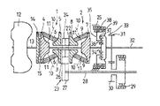
以下,図面を参照して,この発明によるトロイダル型無段変速機の実施例について説明する。図1はこの発明によるトロイダル型無段変速機の一実施例を示す概略図である。図1に示すトロイダル型無段変速機は,ローディングカム,入力ディスク,入力軸の相互の関連構造等を除き,図2のトロイダル型無段変速機の構造と異なるところがないので,同一部品には同一符号を付し,それらの構造についての説明は省略する。
【0031】
エンジンからのトルクはトルクコンバータ12を介して入力軸16に伝達される。入力軸16にはローディングカム19がスプライン(図示せず)で係合し且つ軸方向に移動しないように固定されているので,ローディングカム19は入力軸16と一体に回転することができる。一方のトロイダル変速部18を構成する入力ディスク17は,入力軸16に挿通され,入力軸16に対して回転自在かつ軸方向に摺動自在に支持されている。入力ディスク17はカムローラ15を挟んでローディングカム19に対向して配置されている。カムローラ15はローディングカム19と入力ディスク17が相対回転したときに,入力ディスク17を対向する出力ディスク5に向けて押し付けるスラスト力を発生するような形状としてある。
【0032】
他方のトロイダル変速部2を構成する入力ディスク7は,入力軸16の軸方向に変位可能で且つ入力軸16と一体回転可能である。即ち,入力ディスク7は,例えば,ボールスプラインを介して入力軸16に連結され,入力軸16にねじ込まれたナットとの間に設けられた皿ばねによって対向する出力ディスク8の方へ向けて付勢されており,入力軸16の軸方向に少しだけ変位可能である。入力ディスク7は,ローディングカム19のカム作用で入力軸16が軸方向に変位することに伴って出力ディスク8の方向に向かって変位する。
【0033】
両トロイダル変速部18,2の出力ディスク5,8同士は,図2のものと同様に,一体回転できるように背面同士を連結軸22上にスプライン嵌合等で連結されている。連結軸22は入力軸16に相対回転可能に嵌合された中空軸であって,該中空軸の中間部にスプロケット24が一体的に形成されている。出力ディスク5,8は,連結軸22を介してスラスト方向及びラジアル方向の荷重を支持する軸受(図示せず)によってケーシング25に支持されている。
【0034】
次に,このトロイダル型無段変速機の作動について説明する。このトロイダル型無段変速機の作動のうち,前進走行時において直結クラッチを接続状態にしたときの変速作動を除き,通常の前進走行時における変速作動,及び出力軸が停止状態にあるときに変速を行う場合の変速作動については,図1に示したトロイダル型無段変速機と同じなので,重複説明は省略する。
【0035】
入力軸16の軸方向にスラスト力を発生させる加圧機構は,ローディングカムとカムローラ15とから構成されている。前進用クラッチ29が接続状態にある時,即ち出力ディスク5,8が出力軸32に駆動連結された状態にあるときには,出力ディスク5,8には負荷がかかっているので,入力軸16が回転し,入力軸16と一体のローディングカム19が回転すると,ローディングカム19と入力ディスク17が相対的に回転しようとする。その時,ローディングカム19と入力ディスク17の間にはカムローラ15が介在しているので,入力ディスク17は軸方向にスラスト力を受けて図1の右方向に変位し,出力ディスク5と共に働してパワーローラ6を強く挟みつける。同時に,入力軸16は反作用で図1において左方向に変位するので,入力ディスク7も同方向に変位し,出力ディスク8と協働してパワーローラ9を強く挟み付ける。これにより,入力ディスク17,7の回転はパワーローラ6,9を介して出力ディスク5,8に伝達される。
【0036】
直結クラッチ39を接続すると,入力軸16と出力軸32とは,直結クラッチ39及び遊星歯車機構33を介して直結され,トルクが入力軸16から出力軸32へ直接に伝達できる状態に切り換わる。この状態で前進用クラッチ29を解放すると,チェーン伝動装置23,カウンタ軸28,減速ギヤの歯車30,31から成る逆転機構は空転状態となり,出力ディスク5,8には負荷がかからなくなる。その結果,入力軸16が回転しても,入力ディスク17,7にはローディングカム19からのスラスト力が作用しなくなる。即ち,ローディングカム19と入力ディスク17はほとんど相対回転しない。従って,トロイダル変速部18,2は入力軸16と一体となって空転するだけであって,入力ディスク17,7がパワーローラ6,9に強く押し付けられるようなことはない。また,たとえ,ローディングカム19と入力ディスク17とが相対回転することがあったとしても,出力ディスク5,8が空転状態にあるから,入力ディスク17,7の回転は出力ディスク5,8の回転となって吸収され,結局,入力軸16のトルクは,トロイダル変速部18,2には伝達されず,トロイダル変速部18,2は入力軸16と一体となって空転するだけである。
【0037】
後進走行時には,直結クラッチ39を切って入力軸16と出力軸32を空転状態にすると共に,前進用クラッチ29も切って逆転機構(23,28,30,31)を空転状態にし,後進用クラッチ38を接続させる。後進用クラッチ38が接続されると,キャリヤ35は変速機のケーシング25に対して固定状態になる。この状態では,入力軸16と一体に回転するサンギヤ34の回転は,自転のみ許容されるピニオン35の作用によってリングギヤ37に対して逆回転で伝達され,出力軸32に逆回転が現れる。しかも,この場合には,サンギヤ34の回転は減速してリングギヤ37に伝達されることになる。
【0038】
また,後進走行時には,前進用クラッチ29を切ると,出力ディスク5,8や逆転機構23,28,30,31が空転状態になるので,その結果,入力軸16と共にローディングカム19が回転しても,入力ディスク17,7にはローディングカム19からのスラスト力が作用しない。従って,トロイダル変速部18,2は,後進走行時にも,入力軸16と一体となって空転するだけであって,入力ディスク17,7がパワーローラ6,9に強く押し付けられることはない。
【0039】
上記実施例では,トロイダル型無段変速機をダブルキャビティ式で説明したが,シングルキャビティ式のトロイダル型無段変速機にも適用可能である。また,逆転機構に用いられる第1及び第2伝動手段として,チェーン伝動装置と歯車伝動装置(減速ギヤ)を用いた例を示したが,ベルト伝動装置等の他の伝動装置に用いても良く,また,カウンタ軸の両端での組み合わせにおいても,出力ディスクの回転を逆転して出力軸に伝達するものであれば適用できる。
【0040】
【発明の効果】
この発明によるトロイダル型無段変速機は,上記のように構成されているので,直結クラッチを接続状態にしているときには,加圧機構によるカム作用が起こらないため,トロイダル変速部に動力が伝達されない。それゆえ変速機としてのトルク伝達効率が向上する。しかも,直結クラッチを接続状態にしているときには,トロイダル変速部に動力が伝達されないから,即ち入力ディスクをパワーローラに強く押し付ける力が発生しない。したがって,トロイダル変速部におけるディスクとパワーローラとの接触部におけるフリクションと金属疲労とが軽減されるので,トロイダル変速部の耐久性が向上し,トロイダル変速部の寿命を延ばすことができる。遊星歯車機構は,入力軸とこれに同軸線状に配置された出力軸との間に配置されており,例えば,高速走行時においては,直結クラッチがサンギヤ,キャリヤ及びリングギヤのうちのいずれか二つを固定すべく接続状態に切り換えることで,入力軸と出力軸とは直結クラッチ及び遊星歯車機構を介して直結され,トルクが入力軸から同軸線状に配置された出力軸へ直接に効率良く伝達できる状態に切り換えることができる。更にまた,後進走行も一作動状態にある遊星歯車機構を用いて行われるので,直結クラッチを接続したときだけでなく後進走行時においても,入力ディスクをパワーローラに強く押し付ける力が発生しないため,この点でも,トロイダル変速部の寿命を延ばすことができ,変速機としての寿命を長くすることができる。
【図面の簡単な説明】
【図1】この発明によるトロイダル型無段変速機の一実施例を示す概略図である。
【図2】トロイダル型無段変速機を示す概略図である。
【符号の説明】
2,18 トロイダル変速部
5,8 出力ディスク
6,9 パワーローラ
7,17 入力ディスク
11 傾転軸
15 カムローラ(加圧機構)
16 入力軸
19 ローディングカム(加圧機構)
22 連結軸
23 チェーン伝動装置(第1伝動手段,逆転機構)
25 ケーシング
28 カウンタ軸(逆転機構)
29 前進用クラッチ
30,31 歯車(第2伝動手段,逆転機構)
32 出力軸
33 遊星歯車機構
34 サンギヤ
35 キャリヤ
36 ピニオン
37 リングギヤ
38 後進用クラッチ
39 直結クラッチ[0001]
BACKGROUND OF THE INVENTION
The present invention relates to a toroidal type continuously variable transmission applied to a vehicle such as an automobile.
[0002]
[Prior art]
One of transmissions applied to vehicles such as automobiles is a toroidal continuously variable transmission. A toroidal-type continuously variable transmission generally includes an input disk driven by an input shaft, an output disk disposed opposite to the input disk and drivingly connected to the output shaft, and a power roller in frictional contact with both disks. One or more toroidal transmissions are arranged on the same shaft, and by changing the tilt angle of the power roller, the rotation of the input disk can be changed steplessly and transmitted to the output disk. (For example, refer to Japanese Patent Laid-Open No. 1-193454).
[0003]
In the toroidal-type continuously variable transmission, the power at the time of forward movement is always shifted by the toroidal transmission unit and then output to the output shaft. Therefore, for example, when traveling on a highway for a long time at a constant speed, the power is always transmitted through the toroidal transmission unit even though the gear shifting operation is hardly performed. There is a problem that the lifespan of the device will be shortened. In order to cope with this problem, it has been conventionally proposed to provide a direct coupling clutch for directly coupling an input shaft and an output shaft in a toroidal type continuously variable transmission (for example, Japanese Utility Model Laid-Open No. 63-60750). reference). However, the conventional toroidal-type continuously variable transmission has a structure in which the direct coupling clutch transmits all of the transmission torque, and thus a large capacity direct coupling clutch has to be used.
[0004]
Therefore, the present applicant has incorporated a planetary gear mechanism between the toroidal transmission and the output shaft so that the planetary gear mechanism can bear part of the transmission torque when the direct coupling clutch is connected. A toroidal continuously variable transmission was developed. The toroidal type continuously variable transmission will be described below with reference to FIG.
[0005]
The toroidal type continuously variable transmission of FIG. 2 is a so-called double cavity type toroidal continuously variable transmission in which two sets of toroidal transmission parts are arranged on the same shaft. In this double cavity type toroidal continuously variable transmission, two sets of
[0006]
In the
[0007]
In each
[0008]
In the neutral position where the
[0009]
The
[0010]
A
[0011]
A
[0012]
In addition, a
[0013]
Next, the operation of the toroidal type continuously variable transmission of FIG. 2 will be described. As the engine is driven, power from the engine is input to the
[0014]
During forward travel, the
[0015]
When the main shaft 3 and the
[0016]
During reverse travel, the
[0017]
In order to perform a shift when the
[0018]
[Problems to be solved by the invention]
As described above, in the toroidal type continuously variable transmission shown in FIG. 2, engine power is input to the
[0019]
However, in the toroidal continuously variable transmission, the
[0020]
Therefore, in a toroidal-type continuously variable transmission equipped with a planetary gear mechanism, there is a problem of how to avoid the axial pressing force acting on the toroidal transmission when the direct coupling clutch is engaged. It has become.
[0021]
[Means for Solving the Problems]
SUMMARY OF THE INVENTION An object of the present invention is to solve the above-mentioned problems, and when the direct coupling clutch is in a connected state, power is not transmitted to the toroidal transmission unit, thereby improving the durability of the toroidal transmission unit, and the toroidal transmission unit. It is to provide a toroidal continuously variable transmission capable of extending the service life of the motor.
[0022]
The present invention relates to a pressure mechanism fixed to an input shaft and generating a thrust force in the axial direction of the input shaft, disposed opposite to the pressure mechanism and capable of rotating relative to the input shaft in the axial direction. An input disk supported so as to be displaceable, an output disk disposed opposite to the input disk, and disposed between the input disk and the output disk and in accordance with a tilt angle with respect to the both disks. A power roller for changing the rotation steplessly and transmitting it to the output disk, a reverse rotation mechanism for transmitting the rotation of the output disk reversely to the output shaft, a forward clutch for switching the reverse rotation mechanism to the idling state or the torque transmission state, The planetary gear mechanism provided between the input shaft and the output shaft, and the reverse rotation mechanism in the idle state by the switching of the forward clutch. Possible direct coupling clutch changes directly coupled to the operating state of the gear mechanism and the input shaft and the output shaft, the adult The planetary gear mechanism includes a sun gear that rotates integrally with the input shaft, a carrier that rotatably supports a pinion that meshes with the sun gear, a ring gear that meshes with the pinion and is fixed to the output shaft, The clutch fixes any two of the sun gear, the carrier, and the ring gear to each other to change the operating state of the planetary gear mechanism to a directly connected state between the input shaft and the output shaft. .
[0024]
Since this toroidal continuously variable transmission is configured as described above, the input shaft and the output shaft, in which the direct coupling clutch is connected to the planetary gear mechanism, are idled during normal forward speed shifting. The forward clutch switches the reverse rotation mechanism to the torque transmission state (that is, the direct clutch is disengaged and the forward clutch is engaged). As a result, the rotation of the output disk is transmitted in reverse to the output shaft via the reverse rotation mechanism, so that the output shaft rotates in the same rotational direction as the rotation of the input shaft.
[0025]
During forward direct travel, for example, during high speed travel, the direct clutch is switched to the connected state to fix any two of the sun gear, the carrier, and the ring gear that constitute the planetary gear mechanism. As a result, the input shaft and the output shaft are directly connected via the direct clutch and the planetary gear mechanism, and the torque is switched to a state in which torque can be directly transmitted from the input shaft to the output shaft. Further, since the forward clutch is switched to the non-connected state at the same time as the direct coupling clutch is connected, the reverse rotation mechanism is idled and no load is applied to the output disk. As a result, even if the input shaft rotates, the thrust force from the pressurizing mechanism does not act on the input disk. Therefore, the toroidal transmission unit only idles together with the input shaft, and the input disk is not strongly pressed against the power roller.
[0026]
Since the direct coupling clutch can fix any two of the sun gear, the carrier and the ring gear constituting the planetary gear mechanism, for example, it fixes the input shaft and the carrier to each other. Alternatively, the carrier and the ring gear may be fixed to each other.
[0027]
The planetary gear mechanism is configured to include a reverse clutch that switches the carrier to an idle state or a fixed state with respect to a transmission casing. During reverse travel, the direct coupling clutch is disconnected to idle the input shaft and output shaft, and the forward clutch is also disconnected to cause the reverse rotation mechanism to idle and the reverse clutch is connected. When the reverse clutch is connected, the carrier is fixed to the transmission casing. In this state, the rotation of the sun gear that rotates integrally with the input shaft is transmitted to the ring gear by reverse rotation by the action of the pinion that is allowed only to rotate, and reverse rotation appears on the output shaft. In addition, in this case, the rotation of the sun gear is decelerated and transmitted to the ring gear, which matches the actual situation that the reverse travel speed does not need to be greater than the forward travel speed. In the other travel state, the reverse clutch is in a state where the carrier is idle with respect to the casing of the transmission, and is provided for forward shift travel and forward direct travel.
[0028]
Further, the direct coupling clutch is capable of switching the input shaft and the output shaft to the torque transmission state in response to the reverse clutch placing the carrier in the idling state with respect to the casing. When the direct coupling clutch switches the input shaft and the output shaft to the torque transmission state, the carrier tries to rotate integrally with the input shaft, so that the reverse clutch rotates the carrier with respect to the transmission casing so as not to interfere with the rotation. State.
[0029]
Further, the reverse rotation mechanism includes a counter shaft disposed in parallel to the input shaft, first transmission means for connecting the output disk and one end of the counter shaft, and the other end of the counter shaft and the output shaft. The first transmission means or the second transmission means is a reverse transmission means. Since the output disk rotates in the opposite direction to the input disk, reverse transmission means for reversing the rotation direction is provided in order to match the rotation direction of the input shaft and the rotation direction of the output shaft. The reverse transmission means may be provided somewhere in the transmission path including the counter shaft.
[0030]
DETAILED DESCRIPTION OF THE INVENTION
Embodiments of a toroidal type continuously variable transmission according to the present invention will be described below with reference to the drawings. FIG. 1 is a schematic view showing an embodiment of a toroidal continuously variable transmission according to the present invention. The toroidal type continuously variable transmission shown in FIG. 1 has no difference from the structure of the toroidal type continuously variable transmission of FIG. 2 except for the mutual structure of the loading cam, input disk, and input shaft. The same reference numerals are given, and descriptions of their structures are omitted.
[0031]
Torque from the engine is transmitted to the
[0032]
The input disk 7 constituting the other
[0033]
The
[0034]
Next, the operation of this toroidal continuously variable transmission will be described. Of the operation of this toroidal-type continuously variable transmission, except for the shift operation when the direct clutch is engaged during forward travel, the shift operation during normal forward travel and the shift when the output shaft is stopped Since the speed change operation when performing is the same as that of the toroidal type continuously variable transmission shown in FIG.
[0035]
The pressurizing mechanism that generates a thrust force in the axial direction of the
[0036]
When the
[0037]
During reverse travel, the
[0038]
Further, during reverse travel, if the
[0039]
In the above embodiment, the toroidal type continuously variable transmission has been described as a double cavity type, but it can also be applied to a single cavity type toroidal type continuously variable transmission. Moreover, although the example which used the chain transmission and the gear transmission (reduction gear) was shown as the 1st and 2nd transmission means used for a reverse rotation mechanism, you may use for other transmissions, such as a belt transmission. Also, the combination at both ends of the counter shaft can be applied as long as the rotation of the output disk is reversed and transmitted to the output shaft.
[0040]
【The invention's effect】
Since the toroidal continuously variable transmission according to the present invention is configured as described above, when the direct coupling clutch is in the engaged state, the cam action by the pressurizing mechanism does not occur, so power is not transmitted to the toroidal transmission. . Therefore, torque transmission efficiency as a transmission is improved. Moreover, when the direct clutch is in the engaged state, no power is transmitted to the toroidal transmission, that is, no force is generated that strongly presses the input disk against the power roller. Therefore, friction and metal fatigue at the contact portion between the disc and the power roller in the toroidal transmission unit are reduced, so that the durability of the toroidal transmission unit is improved and the life of the toroidal transmission unit can be extended. The planetary gear mechanism is arranged between an input shaft and an output shaft arranged coaxially with the input shaft. For example, when traveling at high speed, the direct coupling clutch is one of a sun gear, a carrier and a ring gear. The input shaft and output shaft are directly connected via a direct coupling clutch and a planetary gear mechanism by switching the connection state to fix one, and the torque is directly and efficiently transferred from the input shaft to the coaxially arranged output shaft. It can be switched to a state where it can be transmitted. More Also, Since reverse travel is also performed using a planetary gear mechanism in one operating state, Only when the direct clutch is connected. After Even when the vehicle is traveling forward, there is no force that strongly presses the input disk against the power roller, so that the life of the toroidal transmission can be extended and the life of the transmission can be extended.
[Brief description of the drawings]
FIG. 1 is a schematic view showing an embodiment of a toroidal continuously variable transmission according to the present invention.
FIG. 2 is a schematic view showing a toroidal continuously variable transmission.
[Explanation of symbols]
2,18 Toroidal transmission
5,8 output disk
6,9 Power roller
7,17 Input disk
11 Tilt axis
15 Cam roller (Pressure mechanism)
16 Input shaft
19 Loading cam (Pressure mechanism)
22 Connecting shaft
23 Chain transmission (first transmission means, reverse rotation mechanism)
25 casing
28 Counter shaft (reverse rotation mechanism)
29 Forward clutch
30, 31 gear (second transmission means, reverse rotation mechanism)
32 output shaft
33 Planetary gear mechanism
34 Sungear
35 Carrier
36 pinion
37 Ring gear
38 Reverse clutch
39 Direct clutch
Claims (3)
前記遊星歯車機構は前記入力軸と一体に回転するサンギヤ,該サンギヤに噛み合うピニオンを回転自在に支持するキャリヤ及び前記ピニオンと噛み合い前記出力軸に固定されたリングギヤから構成され,また,前記直結クラッチは前記サンギヤ,前記キャリヤ及び前記リングギヤのいずれか二つを相互に固定して前記遊星歯車機構の作動状態を前記入力軸と前記出力軸との直結状態に変更することから成る
トロイダル型無段変速機。A pressure mechanism fixed to the input shaft and generating a thrust force in the axial direction of the input shaft, disposed opposite to the pressure mechanism and supported so as to be rotatable relative to the input shaft and displaceable in the axial direction The input disk, the output disk disposed opposite to the input disk, the input disk disposed between the input disk and the output disk, and the input disk rotating steplessly according to the tilt angle with respect to the both disks A power roller that shifts to the output disk and transmits the output disk to the output disk, a reverse rotation mechanism that transmits the rotation of the output disk to the output shaft that is arranged coaxially with the input shaft, and transmits the reverse rotation mechanism in an idling state or torque transmission. A forward clutch for switching to a state, a planetary gear mechanism provided between the input shaft and the output shaft, and the reverse rotation mechanism by switching the forward clutch. Serial idling state by the planetary gear mechanism capable of changing the direct coupling clutch directly coupled to the operating state and the input shaft and the output shaft of, Ri consists,
The planetary gear mechanism includes a sun gear that rotates integrally with the input shaft, a carrier that rotatably supports a pinion that meshes with the sun gear, and a ring gear that meshes with the pinion and is fixed to the output shaft. the sun gear, the carrier and one or two mutually fixed to the planetary gear mechanism of the operating state of the input shaft and formed Ru toroidal continuously variable from changing directly coupled with the output shaft of the ring gear Machine.
Priority Applications (4)
| Application Number | Priority Date | Filing Date | Title |
|---|---|---|---|
| JP08051198A JP3956475B2 (en) | 1998-03-13 | 1998-03-13 | Toroidal continuously variable transmission |
| DE69908215T DE69908215T2 (en) | 1998-03-13 | 1999-03-10 | Infinitely variable toroidal gear |
| US09/265,375 US6117037A (en) | 1998-03-13 | 1999-03-10 | Toroidal continuous variable transmission |
| EP99301815A EP0942199B1 (en) | 1998-03-13 | 1999-03-10 | Toroidal continuous variable transmission |
Applications Claiming Priority (1)
| Application Number | Priority Date | Filing Date | Title |
|---|---|---|---|
| JP08051198A JP3956475B2 (en) | 1998-03-13 | 1998-03-13 | Toroidal continuously variable transmission |
Publications (2)
| Publication Number | Publication Date |
|---|---|
| JPH11257458A JPH11257458A (en) | 1999-09-21 |
| JP3956475B2 true JP3956475B2 (en) | 2007-08-08 |
Family
ID=13720351
Family Applications (1)
| Application Number | Title | Priority Date | Filing Date |
|---|---|---|---|
| JP08051198A Expired - Fee Related JP3956475B2 (en) | 1998-03-13 | 1998-03-13 | Toroidal continuously variable transmission |
Country Status (4)
| Country | Link |
|---|---|
| US (1) | US6117037A (en) |
| EP (1) | EP0942199B1 (en) |
| JP (1) | JP3956475B2 (en) |
| DE (1) | DE69908215T2 (en) |
Families Citing this family (16)
| Publication number | Priority date | Publication date | Assignee | Title |
|---|---|---|---|---|
| JP2000120822A (en) * | 1998-10-21 | 2000-04-28 | Nsk Ltd | Continuously variable transmission device |
| JP3280633B2 (en) * | 1999-03-24 | 2002-05-13 | 株式会社コミュータヘリコプタ先進技術研究所 | Helicopter power transmission |
| DE10040039A1 (en) * | 2000-08-11 | 2002-02-21 | Daimler Chrysler Ag | Change gear assembly |
| JP2002106665A (en) * | 2000-10-04 | 2002-04-10 | Honda Motor Co Ltd | Double cavity toroidal continuously variable transmission |
| DE10120222A1 (en) * | 2001-04-25 | 2003-01-02 | Zahnradfabrik Friedrichshafen | Clutch arrangement for two-stage infinitely variable change-speed gear has planetary gear link acting as inner blade carrier for one clutch and outer blade carrier for second clutch |
| DE10121042C1 (en) | 2001-04-28 | 2003-05-08 | Daimler Chrysler Ag | Change gear arrangement with a toroidal continuously variable transmission and a planetary gear total gear |
| WO2004031617A2 (en) * | 2002-09-30 | 2004-04-15 | Ulrich Rohs | Gearbox consisting of infinitely variable adjustable partial gear mechanisms |
| BRPI0307387B1 (en) | 2002-09-30 | 2016-07-26 | Rohs Ulrich | planetary transmission |
| JP4739018B2 (en) * | 2002-10-07 | 2011-08-03 | ロース,ウルリヒ | transmission |
| US20110015031A1 (en) * | 2009-07-20 | 2011-01-20 | Jean-Francois Dionne | Continuously variable transmission (cvt) having a coaxial input/output arrangement and enhanced embedded torque transfer |
| US8858389B2 (en) * | 2012-01-27 | 2014-10-14 | Gm Global Technology Operations, Llc | Variator assembly |
| US8888645B2 (en) * | 2012-07-31 | 2014-11-18 | Gm Global Technology Operations, Llc | Simple planetary gearset continuously variable transmission |
| US9638296B2 (en) * | 2012-09-07 | 2017-05-02 | Dana Limited | Ball type CVT including a direct drive mode |
| CN103148187B (en) * | 2013-03-14 | 2017-06-06 | 上海双孚科技发展有限公司 | A kind of array disc type stepless gearbox |
| JP2015017664A (en) * | 2013-07-11 | 2015-01-29 | 日本精工株式会社 | Drive device for electric vehicle |
| WO2016015150A1 (en) * | 2014-07-30 | 2016-02-04 | Transmission Cvtcorp Inc. | Driveline for off-highway vehicles provided with a dual function cvt |
Family Cites Families (14)
| Publication number | Priority date | Publication date | Assignee | Title |
|---|---|---|---|---|
| EP0003408B2 (en) * | 1978-01-21 | 1985-04-03 | P.I.V. Antrieb Werner Reimers GmbH & Co KG | Continuously variable transmission mechanisms |
| DE3212769A1 (en) * | 1982-04-06 | 1983-10-06 | Volkswagenwerk Ag | Transmission arrangement |
| GB2150240B (en) * | 1983-11-17 | 1987-03-25 | Nat Res Dev | Continuously-variable ratio transmission |
| JP2503964B2 (en) * | 1986-04-28 | 1996-06-05 | スズキ株式会社 | Continuously variable transmission |
| JPS6360750A (en) * | 1986-09-01 | 1988-03-16 | Photo Composing Mach Mfg Co Ltd | Printer |
| JPS6360750U (en) * | 1986-10-09 | 1988-04-22 | ||
| GB8629673D0 (en) * | 1986-12-11 | 1987-01-21 | Fellows T G | Automotive transmissions |
| JPH0796901B2 (en) | 1988-01-29 | 1995-10-18 | 日産自動車株式会社 | Friction car type continuously variable transmission |
| JPH01234646A (en) * | 1988-03-12 | 1989-09-19 | Nissan Motor Co Ltd | Toroidal continuously variable transmission |
| JPH0672655B2 (en) | 1988-12-16 | 1994-09-14 | 日産自動車株式会社 | Toroidal type continuously variable transmission |
| JPH06174036A (en) * | 1992-11-30 | 1994-06-21 | Isuzu Motors Ltd | Toroidal type continuously variable transmission |
| JP3391150B2 (en) * | 1995-05-18 | 2003-03-31 | いすゞ自動車株式会社 | Toroidal-type continuously variable transmission for four-wheel drive vehicles |
| US5888160A (en) * | 1996-11-13 | 1999-03-30 | Nsk Ltd. | Continuously variable transmission |
| DE19703544A1 (en) * | 1997-01-31 | 1998-08-06 | Zahnradfabrik Friedrichshafen | Friction gear |
-
1998
- 1998-03-13 JP JP08051198A patent/JP3956475B2/en not_active Expired - Fee Related
-
1999
- 1999-03-10 EP EP99301815A patent/EP0942199B1/en not_active Expired - Lifetime
- 1999-03-10 US US09/265,375 patent/US6117037A/en not_active Expired - Lifetime
- 1999-03-10 DE DE69908215T patent/DE69908215T2/en not_active Expired - Lifetime
Also Published As
| Publication number | Publication date |
|---|---|
| US6117037A (en) | 2000-09-12 |
| EP0942199A3 (en) | 1999-09-29 |
| DE69908215D1 (en) | 2003-07-03 |
| EP0942199A2 (en) | 1999-09-15 |
| DE69908215T2 (en) | 2004-02-12 |
| EP0942199B1 (en) | 2003-05-28 |
| JPH11257458A (en) | 1999-09-21 |
Similar Documents
| Publication | Publication Date | Title |
|---|---|---|
| JP3956475B2 (en) | Toroidal continuously variable transmission | |
| JP3896958B2 (en) | Continuously variable transmission | |
| JPH03223555A (en) | Troidal type continuously variable transmission | |
| JP2929592B2 (en) | Toroidal continuously variable transmission | |
| JP2000120822A (en) | Continuously variable transmission device | |
| JP2778038B2 (en) | Toroidal continuously variable transmission | |
| JPS63219956A (en) | Transmission | |
| JP3666879B2 (en) | Toroidal continuously variable transmission for four-wheel drive vehicles | |
| JP2004232776A (en) | Toroidal type continuously variable transmission | |
| JP3702597B2 (en) | Toroidal type continuously variable transmission | |
| JPH11280867A (en) | Continously variable transmission | |
| JP4085457B2 (en) | Continuously variable transmission | |
| JP2000130531A (en) | Continuously variable transmission | |
| JPH05280627A (en) | Power transmitting device for vehicle | |
| JPH06174036A (en) | Toroidal type continuously variable transmission | |
| JPH11108150A (en) | Troidal type continuously variable transmission | |
| JP4492007B2 (en) | Toroidal continuously variable transmission and continuously variable transmission | |
| JP2001289303A (en) | Continuously variable transmission | |
| JP2002327827A (en) | Infinite variable-speed drive | |
| JPH0830522B2 (en) | Automatic transmission using toroidal type continuously variable transmission | |
| JPH0522095B2 (en) | ||
| JPH11230292A (en) | Toroidal continuously variable transmission | |
| JPH09166195A (en) | Power transmission device having toroidal type continuously variable transmission | |
| JP2005331078A (en) | Continuously variable transmission | |
| JP2004125119A (en) | Continuously-variable transmission |
Legal Events
| Date | Code | Title | Description |
|---|---|---|---|
| A711 | Notification of change in applicant |
Free format text: JAPANESE INTERMEDIATE CODE: A711 Effective date: 20041115 |
|
| A621 | Written request for application examination |
Free format text: JAPANESE INTERMEDIATE CODE: A621 Effective date: 20050310 |
|
| A977 | Report on retrieval |
Free format text: JAPANESE INTERMEDIATE CODE: A971007 Effective date: 20060524 |
|
| A131 | Notification of reasons for refusal |
Free format text: JAPANESE INTERMEDIATE CODE: A131 Effective date: 20060627 |
|
| A521 | Request for written amendment filed |
Free format text: JAPANESE INTERMEDIATE CODE: A523 Effective date: 20060825 |
|
| A131 | Notification of reasons for refusal |
Free format text: JAPANESE INTERMEDIATE CODE: A131 Effective date: 20061205 |
|
| A521 | Request for written amendment filed |
Free format text: JAPANESE INTERMEDIATE CODE: A523 Effective date: 20070205 |
|
| TRDD | Decision of grant or rejection written | ||
| A01 | Written decision to grant a patent or to grant a registration (utility model) |
Free format text: JAPANESE INTERMEDIATE CODE: A01 Effective date: 20070417 |
|
| A61 | First payment of annual fees (during grant procedure) |
Free format text: JAPANESE INTERMEDIATE CODE: A61 Effective date: 20070430 |
|
| R150 | Certificate of patent or registration of utility model |
Free format text: JAPANESE INTERMEDIATE CODE: R150 |
|
| FPAY | Renewal fee payment (event date is renewal date of database) |
Free format text: PAYMENT UNTIL: 20100518 Year of fee payment: 3 |
|
| FPAY | Renewal fee payment (event date is renewal date of database) |
Free format text: PAYMENT UNTIL: 20110518 Year of fee payment: 4 |
|
| FPAY | Renewal fee payment (event date is renewal date of database) |
Free format text: PAYMENT UNTIL: 20120518 Year of fee payment: 5 |
|
| FPAY | Renewal fee payment (event date is renewal date of database) |
Free format text: PAYMENT UNTIL: 20130518 Year of fee payment: 6 |
|
| FPAY | Renewal fee payment (event date is renewal date of database) |
Free format text: PAYMENT UNTIL: 20130518 Year of fee payment: 6 |
|
| FPAY | Renewal fee payment (event date is renewal date of database) |
Free format text: PAYMENT UNTIL: 20140518 Year of fee payment: 7 |
|
| LAPS | Cancellation because of no payment of annual fees |