JP4953998B2 - 人員拘束装置用ガス発生器 - Google Patents
人員拘束装置用ガス発生器 Download PDFInfo
- Publication number
- JP4953998B2 JP4953998B2 JP2007240460A JP2007240460A JP4953998B2 JP 4953998 B2 JP4953998 B2 JP 4953998B2 JP 2007240460 A JP2007240460 A JP 2007240460A JP 2007240460 A JP2007240460 A JP 2007240460A JP 4953998 B2 JP4953998 B2 JP 4953998B2
- Authority
- JP
- Japan
- Prior art keywords
- cylindrical filter
- protrusions
- gas generator
- peripheral wall
- gas
- Prior art date
- Legal status (The legal status is an assumption and is not a legal conclusion. Google has not performed a legal analysis and makes no representation as to the accuracy of the status listed.)
- Active
Links
- 230000002093 peripheral effect Effects 0.000 claims description 46
- 230000000452 restraining effect Effects 0.000 claims description 5
- 239000007789 gas Substances 0.000 description 67
- 238000002485 combustion reaction Methods 0.000 description 15
- 238000000034 method Methods 0.000 description 13
- 239000003795 chemical substances by application Substances 0.000 description 12
- 239000000567 combustion gas Substances 0.000 description 10
- 238000001816 cooling Methods 0.000 description 6
- 238000001914 filtration Methods 0.000 description 4
- 230000015572 biosynthetic process Effects 0.000 description 2
- 238000010586 diagram Methods 0.000 description 2
- 230000009977 dual effect Effects 0.000 description 2
- 230000000694 effects Effects 0.000 description 2
- 230000002401 inhibitory effect Effects 0.000 description 2
- 238000000465 moulding Methods 0.000 description 2
- 238000003466 welding Methods 0.000 description 2
- 239000002826 coolant Substances 0.000 description 1
- 239000002184 metal Substances 0.000 description 1
- 239000000843 powder Substances 0.000 description 1
- 239000003566 sealing material Substances 0.000 description 1
- 238000004804 winding Methods 0.000 description 1
Images


Classifications
-
- B—PERFORMING OPERATIONS; TRANSPORTING
- B60—VEHICLES IN GENERAL
- B60R—VEHICLES, VEHICLE FITTINGS, OR VEHICLE PARTS, NOT OTHERWISE PROVIDED FOR
- B60R21/00—Arrangements or fittings on vehicles for protecting or preventing injuries to occupants or pedestrians in case of accidents or other traffic risks
- B60R21/02—Occupant safety arrangements or fittings, e.g. crash pads
- B60R21/16—Inflatable occupant restraints or confinements designed to inflate upon impact or impending impact, e.g. air bags
- B60R21/26—Inflatable occupant restraints or confinements designed to inflate upon impact or impending impact, e.g. air bags characterised by the inflation fluid source or means to control inflation fluid flow
- B60R21/264—Inflatable occupant restraints or confinements designed to inflate upon impact or impending impact, e.g. air bags characterised by the inflation fluid source or means to control inflation fluid flow using instantaneous generation of gas, e.g. pyrotechnic
- B60R21/2644—Inflatable occupant restraints or confinements designed to inflate upon impact or impending impact, e.g. air bags characterised by the inflation fluid source or means to control inflation fluid flow using instantaneous generation of gas, e.g. pyrotechnic using only solid reacting substances, e.g. pellets, powder
-
- B—PERFORMING OPERATIONS; TRANSPORTING
- B60—VEHICLES IN GENERAL
- B60R—VEHICLES, VEHICLE FITTINGS, OR VEHICLE PARTS, NOT OTHERWISE PROVIDED FOR
- B60R21/00—Arrangements or fittings on vehicles for protecting or preventing injuries to occupants or pedestrians in case of accidents or other traffic risks
- B60R21/02—Occupant safety arrangements or fittings, e.g. crash pads
- B60R21/16—Inflatable occupant restraints or confinements designed to inflate upon impact or impending impact, e.g. air bags
- B60R21/26—Inflatable occupant restraints or confinements designed to inflate upon impact or impending impact, e.g. air bags characterised by the inflation fluid source or means to control inflation fluid flow
- B60R2021/26011—Inflatable occupant restraints or confinements designed to inflate upon impact or impending impact, e.g. air bags characterised by the inflation fluid source or means to control inflation fluid flow using a filter through which the inflation gas passes
-
- B—PERFORMING OPERATIONS; TRANSPORTING
- B60—VEHICLES IN GENERAL
- B60R—VEHICLES, VEHICLE FITTINGS, OR VEHICLE PARTS, NOT OTHERWISE PROVIDED FOR
- B60R21/00—Arrangements or fittings on vehicles for protecting or preventing injuries to occupants or pedestrians in case of accidents or other traffic risks
- B60R21/02—Occupant safety arrangements or fittings, e.g. crash pads
- B60R21/16—Inflatable occupant restraints or confinements designed to inflate upon impact or impending impact, e.g. air bags
- B60R21/26—Inflatable occupant restraints or confinements designed to inflate upon impact or impending impact, e.g. air bags characterised by the inflation fluid source or means to control inflation fluid flow
- B60R21/268—Inflatable occupant restraints or confinements designed to inflate upon impact or impending impact, e.g. air bags characterised by the inflation fluid source or means to control inflation fluid flow using instantaneous release of stored pressurised gas
- B60R21/274—Inflatable occupant restraints or confinements designed to inflate upon impact or impending impact, e.g. air bags characterised by the inflation fluid source or means to control inflation fluid flow using instantaneous release of stored pressurised gas characterised by means to rupture or open the fluid source
Landscapes
- Physics & Mathematics (AREA)
- Fluid Mechanics (AREA)
- Engineering & Computer Science (AREA)
- Mechanical Engineering (AREA)
- Air Bags (AREA)
Description
ガス排出口を有するディフューザシェルとクロージャシェルが接合一体化されたハウジング内に、少なくともガス発生剤、点火器及び筒状フィルタが収容されている人員拘束装置用ガス発生器であり、
前記ハウジングが、天板、周壁面及び底板を有するものであり、
前記天板と前記周壁面の境界にある上側の環状角部及び前記底板と前記周壁面の境界にある下側の環状角部の少なくとも一方において、内側に凹んだ複数の突起部が間隔をおいて形成されており、
前記筒状フィルタの一部が前記複数の突起部により支持固定されており、前記筒状フィルタの外周面と前記ガス排出口との間に間隙が形成されている、人員拘束装置用ガス発生器を提供する。
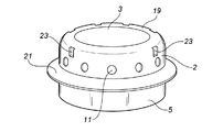
図1は、本発明のガス発生器の軸方向の断面図であり、図2は図1のガス発生器の斜視図である。図3は、複数の突起部の接触円と筒状フィルタの外径との寸法関係を説明するための概略図である。なお、図1、図2で示されるガス発生器は、突起部とそれを利用した筒状フィルタの取り付け方法を除いては公知のものと同じであり、特開2001−225711号公報の図1や、特開2001−97175号公報の図1に示すようなデュアルタイプのガス発生器にも使用することができる。
ガス発生器1は、周壁部2と円形の天板3とからなるディフューザシェル4と、同じく周壁部5と円形の底板6からなるクロージャシェル7が、フランジ21、22において溶接一体化されたハウジング8を有している。
内筒13を接合したディフューザシェル4を、天板3を底にして置く。そして、フィルタ15を4個の突起部23の内側に圧入する。このとき、図3に示すとおり、4個の突起部23の内接円の直径D1よりも、筒状フィルタ15の外径が僅かに大きいため、圧入後の筒状フィルタ15は、突起部23と接する部分が内側に浅く凹んだ状態になって拘束されている。このようにして筒状フィルタ15を取り付けることにより、位置決めができる(即ち、筒状フィルタ15の外周面とハウジング8の周壁部2、5との間に間隙24が形成される)と共に、後の組立工程時に筒状フィルタ15が動かない程度に保持される。
図4は、本発明の別実施形態であるガス発生器の軸方向の断面図であり、図5は図4のガス発生器の斜視図である。図3は、複数の突起部の接触円と筒状フィルタの外径との寸法関係を説明するための概略図である。なお、図4、図5で示されるガス発生器は、突起部とそれを利用した筒状フィルタの取り付け方法を除いては公知のものと同じであり、特開2001−225711号公報の図1や、特開2001−97175号公報の図1に示すようなデュアルタイプのガス発生器にも使用することができる。
ガス発生器100は、周壁部102と円形の天板103とからなるディフューザシェル104と、同じく周壁部105と円形の底板106からなるクロージャシェル107が、フランジ121、122において溶接一体化されたハウジング108を有している。
クロージャシェル107の底板106を底にしてクロージャシェル107を置き、その中央孔174に点火器109を取り付ける。そして、フィルタ115を4個の突起部123の内側に圧入する。このとき、図3に示すとおり、4個の突起部123の内接円の直径D1よりも、筒状フィルタ115の外径が僅かに大きいため、圧入後の筒状フィルタ115は、突起部123と接する部分が内側に浅く凹んだ状態になって拘束されている。このようにして筒状フィルタ115を取り付けることにより、位置決めができる(即ち、筒状フィルタ115の外周面とハウジング108の周壁部102、105との間に間隙124が形成される)と共に、後の組立工程時に筒状フィルタ115が動かない程度に保持される。
4 ディフューザシェル
7 クロージャシェル
8 ハウジング
11 ガス排出口
13 内筒
15 筒状フィルタ
23 突起部
24 間隙
Claims (3)
- ガス排出口(11)を有するディフューザシェル(21)とクロージャシェル(22)が接合一体化されたハウジング(8)内に、少なくともガス発生剤(17)、点火器(9)及び筒状フィルタ(15)が収容されている人員拘束装置用ガス発生器であり、
前記ハウジング(8)が、天板(3)、周壁面(2)及び底板(6)を有するものであり、
前記天板と前記周壁面の境界にある上側の環状角部及び前記底板と前記周壁面の境界にある下側の環状角部の少なくとも一方において、内側に凹んだ複数の突起部(23)が間隔をおいて形成されており、
前記複数の突起部(23)の突き出し高さ(凹みの深さ)が、複数の突起部(23)の先端部を通る接触円の直径(D 1 )が筒状フィルタ(15)の外径よりも僅かに小さくなるように設定されており、
前記筒状フィルタ(15)の一部が前記複数の突起部(23)と接する部分が内側に浅く凹んだ状態になって支持固定されており、
前記筒状フィルタ(15)の外周面と前記ガス排出口(11)との間に間隙(24)が形成されている、人員拘束装置用ガス発生器。 - 前記複数の突起部が、前記周壁面の前記天板に近い部分及び前記周壁面の前記底板に近い部分の少なくとも一方に形成されている、請求項1記載の人員拘束装置用ガス発生器。
- 前記突起部が等間隔で2〜10個形成されている、請求項1又は2記載の人員拘束装置用ガス発生器。
Priority Applications (2)
| Application Number | Priority Date | Filing Date | Title |
|---|---|---|---|
| JP2007240460A JP4953998B2 (ja) | 2007-09-18 | 2007-09-18 | 人員拘束装置用ガス発生器 |
| US12/232,471 US7651129B2 (en) | 2007-09-18 | 2008-09-17 | Gas generator for restraining device |
Applications Claiming Priority (1)
| Application Number | Priority Date | Filing Date | Title |
|---|---|---|---|
| JP2007240460A JP4953998B2 (ja) | 2007-09-18 | 2007-09-18 | 人員拘束装置用ガス発生器 |
Publications (2)
| Publication Number | Publication Date |
|---|---|
| JP2009067338A JP2009067338A (ja) | 2009-04-02 |
| JP4953998B2 true JP4953998B2 (ja) | 2012-06-13 |
Family
ID=40522610
Family Applications (1)
| Application Number | Title | Priority Date | Filing Date |
|---|---|---|---|
| JP2007240460A Active JP4953998B2 (ja) | 2007-09-18 | 2007-09-18 | 人員拘束装置用ガス発生器 |
Country Status (2)
| Country | Link |
|---|---|
| US (1) | US7651129B2 (ja) |
| JP (1) | JP4953998B2 (ja) |
Families Citing this family (12)
| Publication number | Priority date | Publication date | Assignee | Title |
|---|---|---|---|---|
| JP2008018856A (ja) * | 2006-07-13 | 2008-01-31 | Daicel Chem Ind Ltd | 車両の人員拘束装置用ガス発生器 |
| JP4926659B2 (ja) * | 2006-11-07 | 2012-05-09 | 株式会社ダイセル | ガス発生器 |
| MX345766B (es) * | 2008-09-30 | 2017-02-14 | Trw Airbag Sys Gmbh | Inflador, método de fabricación del mismo y módulo que incluye dicho inflador. |
| CN102202943A (zh) * | 2008-10-30 | 2011-09-28 | 奥托里夫Asp股份有限公司 | 安全气囊用充气器 |
| JP5667367B2 (ja) * | 2009-03-06 | 2015-02-12 | オートリブ エー・エス・ピー・インク | エアバッグ装置及びこれに用いるガス発生器 |
| US8997655B1 (en) * | 2009-06-04 | 2015-04-07 | Tk Holdings Inc. | Gas generating system |
| US8684405B2 (en) | 2012-05-17 | 2014-04-01 | Arc Automotive Inc. | Grain retainer construction for air bag inflator |
| JP6422628B2 (ja) * | 2012-10-18 | 2018-11-14 | 株式会社ダイセル | ガス発生剤組成物と、それを使用したガス発生器 |
| DE102014010942A1 (de) * | 2014-07-28 | 2016-01-28 | Trw Airbag Systems Gmbh | Gasgenerator für ein Fahrzeuginsassensicherheitssystem, Gassackmodul und Fahrzeuginsassensicherheitssystem mit einem solchen Gasgenerator sowie Herstellungsverfahren |
| JP6251662B2 (ja) * | 2014-09-29 | 2017-12-20 | 株式会社ダイセル | ガス発生器 |
| CN109353304B (zh) * | 2018-11-06 | 2024-04-23 | 延锋汽车智能安全系统有限责任公司 | 气体发生器和充气式安全装置 |
| JP7369044B2 (ja) * | 2020-01-21 | 2023-10-25 | 株式会社ダイセル | ガス発生器 |
Family Cites Families (13)
| Publication number | Priority date | Publication date | Assignee | Title |
|---|---|---|---|---|
| US3904221A (en) * | 1972-05-19 | 1975-09-09 | Asahi Chemical Ind | Gas generating system for the inflation of a protective bag |
| JPH05178157A (ja) * | 1992-01-08 | 1993-07-20 | Daicel Chem Ind Ltd | エアバッグ用ガス発生器 |
| JPH07251696A (ja) * | 1994-03-15 | 1995-10-03 | Daicel Chem Ind Ltd | エアバッグ用ガス発生器 |
| US6234521B1 (en) * | 1996-04-08 | 2001-05-22 | Daicel Chemical Industries, Ltd. | Airbag inflator and an airbag apparatus |
| JP3218200B2 (ja) | 1996-04-08 | 2001-10-15 | ダイセル化学工業株式会社 | エアバッグ用ガス発生器のクーラント |
| JP3677949B2 (ja) * | 1996-07-17 | 2005-08-03 | 日本化薬株式会社 | エアバッグ用ガス発生器 |
| JPH1095303A (ja) | 1996-07-31 | 1998-04-14 | Daicel Chem Ind Ltd | エアバッグ用ガス発生器及びエアバッグ装置 |
| JPH10315900A (ja) * | 1997-05-15 | 1998-12-02 | Daicel Chem Ind Ltd | エアバッグ用ガス発生器及びエアバッグ装置 |
| CN100348443C (zh) | 1998-09-28 | 2007-11-14 | 大赛璐化学工业株式会社 | 用于气囊的气体发生器以及气囊装置 |
| US6412815B1 (en) * | 1998-09-28 | 2002-07-02 | Daicel Chemical Industries, Ltd. | Gas generator for air bag and air bag device |
| EP1053916B1 (en) * | 1999-02-16 | 2004-05-26 | Daicel Chemical Industries, Ltd. | Gas generator for multi-stage air bag and air bag device |
| CN1419504A (zh) * | 2000-02-22 | 2003-05-21 | 大赛璐化学工业株式会社 | 气囊用气体发生器、偏流部件、冷却/过滤装置支撑部件、冷却器及壳体 |
| JP2001239913A (ja) | 2000-02-28 | 2001-09-04 | Daicel Chem Ind Ltd | エアバッグ用ガス発生器及びエアバッグ装置 |
-
2007
- 2007-09-18 JP JP2007240460A patent/JP4953998B2/ja active Active
-
2008
- 2008-09-17 US US12/232,471 patent/US7651129B2/en active Active
Also Published As
| Publication number | Publication date |
|---|---|
| US7651129B2 (en) | 2010-01-26 |
| US20090091110A1 (en) | 2009-04-09 |
| JP2009067338A (ja) | 2009-04-02 |
Similar Documents
| Publication | Publication Date | Title |
|---|---|---|
| JP4953998B2 (ja) | 人員拘束装置用ガス発生器 | |
| EP1837253B1 (en) | Gas generator for occupant restraining device for vehicle | |
| KR102093194B1 (ko) | 가스 발생기와 그의 조립 방법 | |
| US7503581B2 (en) | Gas generator for occupant restraining device for vehicle | |
| US8011303B2 (en) | Gas generator | |
| US8434783B2 (en) | Gas generator for restraining device of vehicle | |
| JP4907931B2 (ja) | ガス発生器 | |
| CN102791537B (zh) | 气体发生器 | |
| CN104203658B (zh) | 气体发生器和增加燃烧气体的冷却效率和过滤效率的方法 | |
| CN104245437B (zh) | 气体发生器 | |
| CN103442956B (zh) | 用于约束装置的气体发生器 | |
| US8720944B2 (en) | Gas generator for restraining device of vehicle | |
| US8585085B2 (en) | Gas generator | |
| JP3925737B2 (ja) | エアバッグ用ガス発生器 | |
| US8801034B2 (en) | Gas generator for restraining device | |
| JP2008062685A (ja) | 点火器組立体を備えた装置 | |
| JP2021100849A (ja) | ガス発生器 | |
| KR20130041759A (ko) | 가스 발생기 및 그의 조립 방법 | |
| US12441270B2 (en) | Cylindrical filter for pyrotechnic device, manufacturing method for cylindrical filter, and pyrotechnic device using cylindrical filter | |
| CN114424014A (zh) | 点火器组装体以及点火器组装体的组装方法 | |
| JP5541180B2 (ja) | インフレーター | |
| JPH04293643A (ja) | インフレータ組立方法 | |
| JP6710167B2 (ja) | ガス発生器 | |
| JPH0639631U (ja) | エアバッグ用ガス発生器 | |
| JPH081372U (ja) | エアバッグ用ガス発生器 |
Legal Events
| Date | Code | Title | Description |
|---|---|---|---|
| A621 | Written request for application examination |
Free format text: JAPANESE INTERMEDIATE CODE: A621 Effective date: 20100323 |
|
| A521 | Request for written amendment filed |
Free format text: JAPANESE INTERMEDIATE CODE: A523 Effective date: 20110311 |
|
| A977 | Report on retrieval |
Free format text: JAPANESE INTERMEDIATE CODE: A971007 Effective date: 20111226 |
|
| A131 | Notification of reasons for refusal |
Free format text: JAPANESE INTERMEDIATE CODE: A131 Effective date: 20120110 |
|
| A521 | Request for written amendment filed |
Free format text: JAPANESE INTERMEDIATE CODE: A523 Effective date: 20120214 |
|
| TRDD | Decision of grant or rejection written | ||
| A01 | Written decision to grant a patent or to grant a registration (utility model) |
Free format text: JAPANESE INTERMEDIATE CODE: A01 Effective date: 20120306 |
|
| A01 | Written decision to grant a patent or to grant a registration (utility model) |
Free format text: JAPANESE INTERMEDIATE CODE: A01 |
|
| A61 | First payment of annual fees (during grant procedure) |
Free format text: JAPANESE INTERMEDIATE CODE: A61 Effective date: 20120313 |
|
| R151 | Written notification of patent or utility model registration |
Ref document number: 4953998 Country of ref document: JP Free format text: JAPANESE INTERMEDIATE CODE: R151 |
|
| FPAY | Renewal fee payment (event date is renewal date of database) |
Free format text: PAYMENT UNTIL: 20150323 Year of fee payment: 3 |
|
| S531 | Written request for registration of change of domicile |
Free format text: JAPANESE INTERMEDIATE CODE: R313531 |
|
| R350 | Written notification of registration of transfer |
Free format text: JAPANESE INTERMEDIATE CODE: R350 |
|
| R250 | Receipt of annual fees |
Free format text: JAPANESE INTERMEDIATE CODE: R250 |