JP4643630B2 - Processing equipment - Google Patents
Processing equipment Download PDFInfo
- Publication number
- JP4643630B2 JP4643630B2 JP2007305683A JP2007305683A JP4643630B2 JP 4643630 B2 JP4643630 B2 JP 4643630B2 JP 2007305683 A JP2007305683 A JP 2007305683A JP 2007305683 A JP2007305683 A JP 2007305683A JP 4643630 B2 JP4643630 B2 JP 4643630B2
- Authority
- JP
- Japan
- Prior art keywords
- processing unit
- substrate
- unit
- processed
- resist
- Prior art date
- Legal status (The legal status is an assumption and is not a legal conclusion. Google has not performed a legal analysis and makes no representation as to the accuracy of the status listed.)
- Expired - Fee Related
Links
Images


Landscapes
- Liquid Crystal (AREA)
- Exposure And Positioning Against Photoresist Photosensitive Materials (AREA)
- Coating Apparatus (AREA)
- Exposure Of Semiconductors, Excluding Electron Or Ion Beam Exposure (AREA)
- Photosensitive Polymer And Photoresist Processing (AREA)
Description
本発明は、例えば液晶表示装置(LCD)ガラス基板等の被処理基板に対してレジスト塗布および露光後の現像処理を含む一連の処理を施す処理装置に関する。 The present invention relates to a processing apparatus for performing a series of processing including resist coating and development processing after exposure on a target substrate such as a liquid crystal display (LCD) glass substrate.
LCDの製造においては、被処理基板であるLCDガラス基板に、所定の膜を成膜した後、フォトレジスト液を塗布してレジスト膜を形成し、回路パターンに対応してレジスト膜を露光し、これを現像処理するという、いわゆるフォトリソグラフィー技術により回路パターンを形成する。 In the manufacture of LCD, after forming a predetermined film on the LCD glass substrate, which is the substrate to be processed, a photoresist film is applied to form a resist film, and the resist film is exposed corresponding to the circuit pattern, A circuit pattern is formed by a so-called photolithography technique in which this is developed.
このフォトリソグラフィー技術では、被処理基板であるLCD基板は、主な工程として、洗浄処理→脱水ベーク→アドヒージョン(疎水化)処理→レジスト塗布→プリベーク→露光→現像→ポストベークという一連の処理を経てレジスト層に所定の回路パターンを形成する。 In this photolithography technique, the LCD substrate as a substrate to be processed is subjected to a series of processes including cleaning processing → dehydration baking → adhesion (hydrophobization) processing → resist coating → prebaking → exposure → development → post baking. A predetermined circuit pattern is formed on the resist layer.
従来、このような処理は、各処理を行う処理ユニットを搬送路の両側にプロセスフローを意識した形態で配置し、搬送路を走行可能な中央搬送装置により各処理ユニットへの被処理基板の搬入出を行うプロセスブロックを一または複数配置してなる処理システムにより行われている。このような処理システムは、基本的にランダムアクセスであるから処理の自由度が極めて高い。 Conventionally, in such processing, processing units for performing each processing are arranged on both sides of the transport path in consideration of the process flow, and a substrate to be processed is carried into each processing unit by a central transport apparatus that can travel on the transport path. This is performed by a processing system in which one or a plurality of process blocks to be output are arranged. Since such a processing system is basically random access, the degree of freedom of processing is extremely high.
しかしながら、上記処理システムは基本的に閉鎖系であり、搬入出部であるカセットステーションに成膜処理等の前工程が終了した被処理基板を収納したカセットをセットし、カセット内の被処理基板を順次処理した後、再びカセットに収納し、そのカセットをエッチング等の後工程に搬送するという作業が必要であり、このような作業が処理のスループット向上を阻害する要因となっている。 However, the above processing system is basically a closed system, and a cassette containing a substrate to be processed for which a previous process such as a film forming process has been completed is set in a cassette station which is a loading / unloading unit. After sequential processing, it is necessary to store the cassette in the cassette again and transport the cassette to a subsequent process such as etching, which is a factor that hinders improvement in processing throughput.
一方、近時、LCD基板は大型化の要求が強く、一辺が1mにも及ぶような巨大なものまで出現するに至り、上述のような平面的な配置を有する処理システムではフットプリントが極めて大きなものとなってしまい、省スペースの観点からフットプリントの縮小が強く求められているが、上記中央搬送装置ではフットプリント縮小の要請を満たすことは困難である。 On the other hand, recently, there is a strong demand for a large-sized LCD substrate, and even a huge one having a side as long as 1 m has appeared, and the processing system having the above-described planar arrangement has a very large footprint. However, from the viewpoint of space saving, there is a strong demand for reducing the footprint. However, it is difficult for the central transport apparatus to satisfy the demand for reducing the footprint.
本発明はかかる事情に鑑みてなされたものであって、被処理基板に対してレジスト塗布および露光後の現像処理を含む一連の処理を、その前工程および後工程を含めて高スループットで行うことができる処理装置を提供することを目的とする。またこのようなことに加えて、フットプリントを極力小さくすることができる処理装置を提供することを目的とする。 The present invention has been made in view of such circumstances, and performs a series of processes including resist coating and development processing after exposure on a substrate to be processed at a high throughput including its pre-process and post-process. An object of the present invention is to provide a processing apparatus that can perform the above-described processing. Another object of the present invention is to provide a processing apparatus capable of minimizing the footprint as much as possible.
上記課題を解決するために、本発明の第1の観点では、被処理基板に対してレジスト塗布および露光後の現像を含む一連の処理を行う処理装置であって、被処理基板が第1の方向に略水平に搬送されつつ洗浄液による洗浄処理および乾燥処理が行われる洗浄処理ユニットと、被処理基板が前記第1の方向に略水平に搬送されつつレジスト液の塗布を含むレジスト処理が行われるレジスト処理ユニットと、現像液塗布、現像後の現像液除去、および乾燥処理を行う現像処理ユニットと、を有し、前記洗浄処理ユニットおよび前記レジスト処理ユニットと、前記現像処理ユニットとは、露光装置を挟んで両側に設けられ、前記レジスト処理ユニットが、前記洗浄処理ユニットと空間を隔てて相対向するように設けられ、前記洗浄処理ユニット及び前記レジスト処理ユニットの一方の端部に隣接して設けられ、前記洗浄処理ユニット及び第1のパスユニットを介して前記レジスト処理ユニットへの被処理基板の搬入を行う第1の搬送装置と、前記洗浄処理ユニット及び前記レジスト処理ユニットの他方の端部に隣接して設けられ、第2のパスユニットを介して前記洗浄処理ユニット及び第3のパスユニットを介して前記レジスト処理ユニットからの被処理基板の搬出を行う第2の搬送装置と、被処理基板を載置した状態で前記空間中を移動自在な載置移動手段と、を備え、前記載置移動手段が、前記第2の搬送装置から前記洗浄および乾燥処理された被処理基板を受け取り、前記空間中を前記第1の方向とは逆の第2の方向に移動し、前記第1の搬送装置が、前記空間中を移動してきた前記載置移動手段から前記洗浄および乾燥処理された被処理基板を受け取り、前記第1のパスユニットを介して前記レジスト処理ユニットに搬入するように構成されていることを特徴とする処理装置を提供する。
In order to solve the above-described problems, according to a first aspect of the present invention, there is provided a processing apparatus for performing a series of processing including resist coating and development after exposure on a substrate to be processed. A cleaning processing unit that performs cleaning processing and drying processing using a cleaning liquid while being transported substantially horizontally in a direction, and a resist processing that includes application of a resist solution while a substrate to be processed is transported substantially horizontally in the first direction. A resist processing unit, and a development processing unit that performs developer coating, developer removal after development, and drying processing, and the cleaning processing unit, the resist processing unit, and the development processing unit are an exposure apparatus. The resist processing unit is provided so as to face the cleaning processing unit with a space therebetween, and the cleaning processing unit and Serial resist processing one end provided adjacent to the unit, a first conveying device which performs loading of the substrate into the resist processing unit through the cleaning unit and the first path unit, wherein A substrate to be processed from the resist processing unit via the second pass unit , provided adjacent to the other end of the cleaning processing unit and the resist processing unit, via the cleaning processing unit and the third pass unit A second transfer device that carries out the unloading, and a placement movement means that is movable in the space with the substrate to be processed placed thereon, wherein the placement movement means is provided from the second transfer device. The substrate to be processed that has been cleaned and dried is received, moved in the space in the second direction opposite to the first direction, and before the first transport device has moved in the space. Receive a substrate to be processed, which is the cleaning and drying process from placing mobile unit, to provide a processing apparatus characterized by being configured to carry the resist processing unit through the first pass unit .
本発明の第2の観点では、被処理基板が第1の方向に略水平に搬送されつつ洗浄液による洗浄処理および乾燥処理が行われる洗浄処理ユニットと、前記洗浄処理ユニットと空間を隔てて相対向するように設けられ、被処理基板が前記第1の方向に略水平に搬送されつつレジスト液の塗布を含むレジスト処理が行われるレジスト処理ユニットと、前記洗浄処理ユニット及び前記レジスト処理ユニットの一方の端部に隣接して設けられ、前記洗浄処理ユニット及び第1のパスユニットを介して前記レジスト処理ユニットへの被処理基板の搬入を行う第1の搬送装置と、前記洗浄処理ユニット及び前記レジスト処理ユニットの他方の端部に隣接して設けられ、第2のパスユニットを介して前記洗浄処理ユニット及び第3のパスユニットを介して前記レジスト処理ユニットからの被処理基板の搬出を行う第2の搬送装置と、被処理基板を載置した状態で前記空間中を移動自在な載置移動手段と、を備え、前記載置移動手段が、前記第2の搬送装置から前記洗浄および乾燥処理された被処理基板を受け取り、前記空間中を前記第1の方向とは逆の第2の方向に移動し、前記第1の搬送装置が、前記空間中を移動してきた前記載置移動手段から前記洗浄および乾燥処理された被処理基板を受け取り、前記第1のパスユニットを介して前記レジスト処理ユニットに搬入するように構成されていることを特徴とする処理装置を提供する。
In a second aspect of the present invention, a cleaning processing unit in which a cleaning process and a drying process are performed with a cleaning liquid while a substrate to be processed is transported substantially horizontally in a first direction, and the cleaning processing unit is opposed to each other with a space therebetween. A resist processing unit that performs resist processing including application of a resist solution while the substrate to be processed is transported substantially horizontally in the first direction, and one of the cleaning processing unit and the resist processing unit. A first transfer device that is provided adjacent to an end and carries a substrate to be processed into the resist processing unit via the cleaning processing unit and the first pass unit ; the cleaning processing unit; and the resist processing provided adjacent the other end of the unit, said through the cleaning unit and the third pass unit through the second pass unit A second transfer device that carries out the substrate to be processed from the dyst processing unit; and a placement moving means that is movable in the space in a state where the substrate to be processed is placed. The substrate to be processed that has been subjected to the cleaning and drying process is received from the second transport device, moved in the space in a second direction opposite to the first direction, and the first transport device is The substrate to be processed that has been cleaned and dried is received from the placement moving means that has moved in the space, and is loaded into the resist processing unit via the first pass unit. A processing apparatus is provided.
本発明の第3の観点では、被処理基板が第1の方向に略水平に搬送されつつ洗浄液による洗浄処理および乾燥処理が行われる洗浄処理ユニットと、前記洗浄処理ユニットと空間を隔てて相対向するように設けられ、被処理基板が前記第1の方向に略水平に搬送されつつレジスト液の塗布を含むレジスト処理が行われるレジスト処理ユニットと、前記洗浄処理ユニット及び前記レジスト処理ユニットの一方の端部に設けられ、前記一方の端部に設けられた第1のパスユニット、及び前記レジスト処理ユニットの搬入口側に設けられた第2のパスユニットを含む第1の熱的処理ユニットセクションと、前記洗浄処理ユニット及び前記レジスト処理ユニットの他方の端部に設けられ、前記洗浄処理ユニットの搬出口側に設けられた第3のパスユニット、前記レジスト処理ユニットの搬出口側に設けられた第4のパスユニット、前記他方の端部に設けられたパス・クーリングユニットを含む第2の熱的処理ユニットセクションと、前記第1の熱的処理ユニットセクションに隣接して設けられた第1の搬送装置と、前記第2の熱的処理ユニットセクションに隣接して設けられた第2の搬送装置と、被処理基板を載置した状態で前記空間中を移動自在な載置移動手段と、を備え、前記第1の搬送装置が、被処理基板を前記第1のパスユニットから前記洗浄処理ユニットへ搬送し、前記第2の搬送装置が、洗浄および乾燥処理された被処理基板を前記第3のパスユニットから前記載置移動手段へ搬送し、前記載置移動手段が、前記空間中を前記第1の方向とは逆の第2の方向に、洗浄および乾燥処理された被処理基板を前記第1の搬送装置に隣接する位置まで被処理基板を移動させ、前記第1の搬送装置が、洗浄および乾燥処理された被処理基板を、前記空間中を移動してきた前記載置移動手段から前記第2のパスユニットへ搬送し、前記第2の搬送装置が、レジスト処理された被処理基板を前記第4のパスユニットから前記パス・クーリングユニットへ搬送するように構成されていることを特徴とする処理装置を提供する。
In a third aspect of the present invention, a cleaning processing unit in which a cleaning process and a drying process with a cleaning liquid are performed while a substrate to be processed is transported substantially horizontally in a first direction, and the cleaning processing unit is opposed to each other across a space. A resist processing unit that performs resist processing including application of a resist solution while the substrate to be processed is transported substantially horizontally in the first direction, and one of the cleaning processing unit and the resist processing unit. A first thermal processing unit section including a first pass unit provided at an end and a second pass unit provided on a carry-in entrance side of the resist processing unit; A third pass unit provided at the other end of the cleaning processing unit and the resist processing unit and provided on the carry-out side of the cleaning processing unit. A second thermal processing unit section including a fourth pass unit provided on the carry-out side of the resist processing unit, a pass cooling unit provided at the other end, and the first thermal unit A first transfer device provided adjacent to the processing unit section, a second transfer device provided adjacent to the second thermal processing unit section, and the substrate to be processed placed Mounting movement means movable in the space, the first transport device transports the substrate to be processed from the first pass unit to the cleaning processing unit, the second transport device, The substrate to be processed that has been cleaned and dried is transported from the third path unit to the placement movement means, and the placement movement means moves in the space in a second direction opposite to the first direction. Cleaning and drying process The processed substrate is moved to a position adjacent to the first transfer device, and the first transfer device has moved the cleaned and dried substrate to be processed in the space. Conveying from the placement moving means to the second pass unit, the second transport device is configured to transport the resist-treated substrate from the fourth pass unit to the pass cooling unit. that is to provide a processing apparatus according to claim.
本発明の第4の観点では、被処理基板に対して洗浄、レジスト塗布および露光後の現像を含む一連の処理を行う処理装置であって、露光装置の上流側に設けられた前段処理部と、露光装置の下流側に設けられた後段処理部と、前記前段処理部から前記露光装置へ被処理基板を受け渡す第1のインターフェイス部と、前記露光装置から前記後段処理部へ被処理基板を受け渡す第2のインターフェイス部とを具備し、前記前段処理部は、被処理基板が搬入される搬入部と、被処理基板が第1の方向に略水平に搬送されつつ洗浄液による洗浄処理および乾燥処理が行われる洗浄処理ユニットと、被処理基板が前記第1の方向に略水平に搬送されつつレジスト液の塗布を含むレジスト処理が行われ、空間を介して前記洗浄処理ユニットと対向して設けられたレジスト処理ユニットと、前記洗浄処理ユニットから搬出された被処理基板に対し所定の熱的処理を行う複数の熱的処理ユニットが集約された第1の熱的処理ユニットセクションと、前記レジスト処理ユニットから搬出された被処理基板に対し所定の熱的処理を行う複数の熱的処理ユニットが集約された第2の熱的処理ユニットセクションと、前記洗浄処理ユニットと前記レジスト処理ユニットとの間の空間を移動可能に設けられ、前記洗浄処理ユニットから搬出された被処理基板を載置した状態で前記空間中を前記第1の方向とは逆の第2の方向に移動し、前記レジスト処理ユニットへの搬入可能位置に被処理基板を移動させる載置移動手段とを有し、前記後段処理部は、被処理基板が略水平に搬送されつつ、現像液塗布、現像後の現像液除去、および乾燥処理を行う現像処理ユニットと、前記現像処理ユニットから搬出された被処理基板に対し所定の熱的処理を行う複数の熱的処理ユニットが集約された第3の熱的処理ユニットセクションと、被処理基板が搬出される搬出部とを有することを特徴とする処理装置を提供する。
According to a fourth aspect of the present invention, there is provided a processing apparatus that performs a series of processing including cleaning, resist coating, and development after exposure on a substrate to be processed, a pre-processing unit provided upstream of the exposure apparatus; A post-processing unit provided on the downstream side of the exposure apparatus; a first interface unit that delivers the substrate to be processed from the pre-processing unit to the exposure apparatus; and a substrate to be processed from the exposure apparatus to the post-processing unit. A second interface unit for delivering, and the pre-processing unit includes a carry-in unit into which a substrate to be processed is carried, a cleaning process using a cleaning liquid and drying while the substrate to be processed is transported substantially horizontally in the first direction. a cleaning unit which processes are performed, the resist processing including the application of the resist solution while being conveyed substantially horizontally to the substrate to be processed the first direction is performed, provided to face the cleaning process unit via the space A resist processing unit, a first thermal processing unit section in which a plurality of thermal processing units for performing predetermined thermal processing on a substrate to be processed unloaded from the cleaning processing unit are integrated, and the resist processing A second thermal processing unit section in which a plurality of thermal processing units for performing predetermined thermal processing on the substrate to be processed unloaded from the unit are integrated; and between the cleaning processing unit and the resist processing unit. The resist processing unit is provided so as to be movable in the space, and moves in the second direction opposite to the first direction in the space with the substrate to be processed unloaded from the cleaning processing unit placed thereon. And a post-processing unit that moves the substrate to be loaded to a position where the substrate to be loaded can be carried into the substrate. A third thermal process in which a development processing unit that performs image liquid removal and drying processing and a plurality of thermal processing units that perform predetermined thermal processing on the target substrate carried out of the development processing unit are integrated. There is provided a processing apparatus having a unit section and a carry-out unit from which a substrate to be processed is carried out.
上記本発明の第4の観点において、前記前段処理部は、前記洗浄処理ユニットおよび前記レジスト処理ユニットのいずれも、前記搬入部側に搬入口を有し、前記第1のインターフェイス部側に搬出口を有し、前記第1の熱的処理ユニットセクションは前記搬入部に隣接して設けられ、前記第2の熱的処理ユニットセクションは前記第1のインターフェイス部に隣接して設けられ、前記搬入部の被処理基板を前記洗浄処理ユニットに受け渡し、かつ前記載置移動手段に載置された被処理基板を前記第1の熱的処理ユニットセクションへ受け渡すとともに前記第1の熱的処理ユニットセクションからの被処理基板を第1のパスユニットを介して前記レジスト処理ユニットへ受け渡す第1の搬送装置と、前記洗浄処理ユニットから搬出された被処理基板を第2のパスユニットを介して前記載置移動手段に受け渡し、かつ、前記レジスト処理ユニットから搬出された被処理基板を第3のパスユニットを介して前記第2の熱的処理ユニットセクションへ受け渡すとともに前記第2の熱的処理ユニットセクションからの被処理基板を第4のパスユニットを介して前記第1のインターフェイス部へ受け渡す第2の搬送装置とをさらに有するように構成することができる。 In the fourth aspect of the present invention described above, the pre-processing unit has a carry-in port on the carry-in unit side and a carry-out port on the first interface unit side in both the cleaning processing unit and the resist processing unit. The first thermal processing unit section is provided adjacent to the carry-in portion, and the second thermal processing unit section is provided adjacent to the first interface portion, and the carry-in portion The substrate to be processed is transferred to the cleaning processing unit, and the substrate to be processed placed on the placement moving means is transferred to the first thermal processing unit section and from the first thermal processing unit section. the resist a first conveying device for passing to the processing unit, the processing is carried out from the cleaning unit via the first path unit substrate to be processed Passing to said placing the moving means the plate through the second pass unit, and the resist process the substrate to be processed is unloaded from the unit to the third through said path unit of a second thermal processing unit section And a second transfer device that transfers the substrate to be processed from the second thermal processing unit section to the first interface unit via a fourth pass unit. it can.
また、前記後段処理部は、前記搬出部に隣接して前記第3の熱的処理ユニットセクションを有し、前記第2のインターフェイス部の被処理基板を前記現像処理ユニットに受け渡す第3の搬送装置と、前記現像処理ユニットから搬出された基板を前記第3の熱的処理ユニットセクションへ受け渡すとともに前記第3の熱的処理ユニットセクションからの被処理基板を前記搬出部へ受け渡す第4の搬送装置とをさらに有するように構成することができる。 The post-processing unit includes the third thermal processing unit section adjacent to the carry-out unit, and transfers the substrate to be processed of the second interface unit to the development processing unit. And a fourth apparatus for transferring a substrate unloaded from the development processing unit to the third thermal processing unit section and a substrate to be processed from the third thermal processing unit section to the unloading section. It can comprise so that it may further have a conveyance device.
さらに、前記第1、第2および第3の熱的処理ユニットセクションは、それぞれ、複数の熱的処理ユニットが垂直方向に積層して構成された熱的処理ユニットブロックを有するように構成することができる。 Further, each of the first, second and third thermal processing unit sections may be configured to have a thermal processing unit block configured by stacking a plurality of thermal processing units in a vertical direction. it can.
本発明によれば、レジスト処理ユニットと、現像処理ユニットとは、露光装置を挟んで両側に設けられており、洗浄処理ユニットが存在する場合には、露光装置を挟んで一方側に洗浄処理ユニットおよびレジスト処理ユニットが存在し、他方側に現像処理ユニットが存在するようにこれらが配置されているので、このような処理装置を用いることにより、その前工程、例えば成膜工程と、本処理装置におけるレジスト塗布・露光・現像と、その後工程、例えばエッチング工程とを連続して行うことが可能となり、全体的な処理のスループットを高めることができる。 According to the present invention, the resist processing unit and the development processing unit are provided on both sides of the exposure apparatus, and when there is a cleaning processing unit, the cleaning processing unit is provided on one side of the exposure apparatus. And the resist processing unit, and these are arranged so that the development processing unit exists on the other side. By using such a processing apparatus, the preceding process, for example, the film forming process, and the present processing apparatus The resist coating / exposure / development and the subsequent steps, for example, the etching step, can be performed continuously, and the throughput of the overall processing can be increased.
また、上記に加え、レジスト処理ユニット、現像処理ユニット、洗浄処理ユニットが、被処理基板が略水平に搬送されつつ所定の処理が行われるように構成されることにより、従来のような複数の処理ユニットの間を走行する大がかりな中央搬送装置およびそれが走行する中央搬送路が基本的に不要となり、その分省スペース化を図ることができフットプリントを小さくすることができる。 In addition to the above, the resist processing unit, the development processing unit, and the cleaning processing unit are configured such that predetermined processing is performed while the substrate to be processed is transported substantially horizontally, so that a plurality of conventional processing can be performed. A large-scale central transport device that travels between units and a central transport path on which it travels are basically unnecessary, so that space can be saved and the footprint can be reduced.
さらに、露光装置の上流側の前段処理部に、被処理基板が略水平に搬送されつつ所定の処理が行われるように構成された洗浄処理ユニットおよびレジスト処理ユニットを配し、かつ露光装置の下流側の後段処理部に、被処理基板が略水平に搬送されつつ所定の処理が行われるように構成された現像処理ユニットを配するとともに、複数の熱的処理ユニットが、これら洗浄処理、レジスト処理、現像処理に対応するもの毎に集約された第1、第2および第3の熱的処理ユニットセクションを構成するようにしたので、高いスループットを維持しつつ、よりフットプリントを小さくすることができる。 In addition, a cleaning processing unit and a resist processing unit configured to perform predetermined processing while the substrate to be processed is transported substantially horizontally are arranged in the upstream processing unit on the upstream side of the exposure apparatus, and downstream of the exposure apparatus. A development processing unit configured to perform predetermined processing while the substrate to be processed is transported substantially horizontally is disposed in the subsequent processing unit on the side, and a plurality of thermal processing units include these cleaning processing and resist processing. Since the first, second, and third thermal processing unit sections aggregated for each corresponding to the development processing are configured, the footprint can be further reduced while maintaining high throughput. .
さらにまた、上記に加え、前段処理部において、洗浄処理ユニットとレジスト処理ユニットとを空間を介して対向するように設け、その空間を移動するシャトルにより洗浄処理ユニットから搬出された被処理基板をレジスト処理ユニットへの搬入可能位置に搬送するようにしたので、前段処理部において洗浄処理ユニットおよびレジスト処理ユニットを一列に配置した場合よりも省スペース化を図ることができ、より一層フットプリントを小さくすることができる。 Further, in addition to the above, in the pre-processing section, the cleaning processing unit and the resist processing unit are provided so as to face each other through a space, and the substrate to be processed unloaded from the cleaning processing unit by the shuttle that moves in the space is registered. Since it is transported to a position where it can be loaded into the processing unit, space can be saved and the footprint can be further reduced compared to the case where the cleaning processing unit and the resist processing unit are arranged in a row in the pre-processing unit. be able to.
以下、本発明の実施の形態を添付図面を参照して詳細に説明する。
図1は本発明の一実施形態に係るLCDガラス基板のレジスト塗布現像処理装置を示す平面図である。
Hereinafter, embodiments of the present invention will be described in detail with reference to the accompanying drawings.
FIG. 1 is a plan view showing an LCD glass substrate resist coating and developing apparatus according to an embodiment of the present invention.
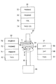
このレジスト塗布現像処理装置100は、露光装置3を挟んで設けられた前段処理部1および後段処理部2を有している。前段処理部1と露光装置3との間には第1のインターフェイス部4が設けられ、露光部3と後段処理部2との間には第2のインターフェイス部5が設けられている。そして、前段処理部1へはITO(インジウム−スズ酸化物)膜成膜処理等の前処理工程を行う装置で所定の処理が施されたLCDガラス基板Gが一枚ずつ受け渡され、後段処理部2から処理後の基板Gがエッチング処理等の後処理を行う装置へ受け渡されるようになっている。なお、図1において、レジスト塗布現像処理装置100の長手方向をX方向、平面上においてX方向と直交する方向をY方向とする。
The resist coating and developing
前段処理部1においては、X方向に沿ってスクラブ洗浄処理ユニット(SCR)21とレジスト処理ユニット23とが空間20を隔てて相対向するように設けられている。前段処理部1の露光装置3と反対側の端部に加熱や冷却を伴う熱的処理を行う熱的処理ユニットが集合した第1の熱的処理ユニットセクション24が設けられており、そこに後述する成膜処理等の前処理工程から搬送されてきた基板Gの受け渡しを行うパスユニット(PASS)が設けられている。また、露光装置3側の端部には第1のインターフェイス部4に隣接するように第2の熱的処理ユニットセクション25が設けられている。スクラブ洗浄処理ユニット(SCR)21の上の端部側の一部分にはエキシマUV照射ユニット(e−UV)22が設けられている。このエキシマUV照射ユニット(e−UV)22はスクラブ洗浄に先立って基板Gの有機物を除去するために設けられている。
In the pre-stage processing unit 1, a scrub cleaning processing unit (SCR) 21 and a resist
空間20内には、第1の熱的処理ユニットセクション24に隣接した第1の搬送装置26と、第2の熱的処理ユニットセクション25に隣接した第2の搬送装置27とが設けられており、また、空間20内には、基板Gを載置した状態でその中を移動自在な載置移動手段としてシャトル28が設けられている。そしてこのシャトル28は後述するように基板Gを保持して第2の搬送装置27から第1の搬送装置26へ基板Gを搬送する。
In the
上記スクラブ洗浄処理ユニット(SCR)21は、その中で基板Gが従来のように回転されることなく、略水平に搬送されつつ洗浄処理および乾燥処理を行うようになっている。スクラブ洗浄処理ユニット(SCR)21では、基板Gの搬送は例えばコロ搬送またはベルト搬送により行われ、基板Gの搬入口および搬出口は空間20に面して、それぞれ第1および第2の搬送装置26および27に対応する位置に設けられており、基板Gの搬入は第1の搬送装置26で行われ、搬出は第2の搬送装置27で行われる。なお、エキシマUV照射ユニット(e−UV)22の搬入出口は空間20に面して第1の搬送装置26に対応する位置に設けられており、第1の搬送装置26により基板Gの搬入出が行われるようになっている。
The scrub cleaning unit (SCR) 21 performs the cleaning process and the drying process while the substrate G is transported substantially horizontally without being rotated in the conventional manner. In the scrub cleaning processing unit (SCR) 21, the substrate G is transported by, for example, roller transport or belt transport, and the carry-in port and the carry-out port of the substrate G face the
レジスト処理ユニット23は、図2のその内部の平面図に示すように、カップ50内で基板Gをスピンチャック51により回転させつつ図示しないノズルからレジスト液を滴下させて塗布するレジスト塗布処理装置(CT)23a、基板G上に形成されたレジスト膜を減圧容器52内で減圧乾燥する減圧乾燥装置(VD)23b、およびステージ54に載置された基板Gの四辺をスキャン可能な溶剤吐出ヘッド53により基板Gの周縁に付着した余分なレジストを除去する周縁レジスト除去装置(ER)23cがその順に配置されており、ガイドレール55にガイドされて移動する一対のサブアーム56により基板Gがこれらの間を略水平に搬送される。このレジスト処理ユニット23は、相対向する短辺に基板Gの搬入口57および搬出口58が設けられており、ガイドレール55はこれら搬入口57および搬出口58から外側に延びてサブアーム56により基板Gの受け渡しが可能となっている。
2, the resist processing
第1の熱的処理ユニットセクション24は、基板Gに熱的処理を施す熱的処理ユニットが積層して構成された2つの熱的処理ユニットブロック(TB)29,30を有しており、熱的処理ユニットブロック(TB)29は前段処理部1の露光装置3と反対側の端部に設けられ、熱的処理ユニットブロック(TB)30はレジスト処理ユニット23の搬入口側に設けられている。図3の側面図に示すように、熱的処理ユニットブロック(TB)29は、下から順に前工程からの基板Gの搬入を行うパスユニット(PASS)61、基板Gを冷却するクーリングユニット(COL)62、基板Gに対して疎水化処理を施すアドヒージョン処理ユニット(AD)63が3段積層されて構成されており、熱的処理ユニットブロック(TB)30は、下から順に基板Gの受け渡しを行うパスユニット(PASS)64、クーリングユニット(COL)65、アドヒージョン処理ユニット(AD)66が3段積層されて構成されている。第1の搬送装置26は、前工程の処理が終了した後の基板Gをパスユニット(PASS)61を介して搬入し、上記複数の熱的処理ユニットに対する基板Gの搬入出、パスユニット(PASS)64を介してのレジスト処理ユニット23への基板Gの受け渡し、およびシャトル28上の基板Gの受け取りを行う。
The first thermal
第1の搬送装置26は、図3に示すように、上下に延びるガイドレール91と、ガイドレールに沿って昇降する昇降部材92と、昇降部材92上を旋回可能に設けられたベース部材93と、ベース部材93上を前進後退可能に設けられ、基板Gを保持する基板保持アーム94とを有している。そして、昇降部材92の昇降はモーター95によって行われ、ベース部材93の旋回はモーター96によって行われ、基板保持アーム94の前後動はモーター97によって行われる。第1の搬送装置26はこのように上下動、前後動、旋回動可能に設けられているので、熱的処理ユニットブロック(TB)29,30のいずれのユニットにもアクセス可能である。
As shown in FIG. 3, the
第2の熱的処理ユニットセクション25は、基板Gに熱的処理を施す熱的処理ユニットが積層して構成された3つの熱的処理ユニットブロック(TB)31,32,33を有しており、熱的処理ユニットブロック(TB)31は、スクラブ洗浄処理ユニット(SCR)21の搬出口側に設けられ、熱的処理ユニットブロック(TB)32はレジスト処理ユニット23の搬出口側に設けられ、熱的処理ユニットブロック(TB)33は、第1のインターフェイス部4に隣接して設けられている。図4の側面図に示すように、熱的処理ユニットブロック(TB)31は、下から順に基板Gの受け渡しを行うパスユニット(PASS)67、基板Gに対して脱水ベーク処理を行う2つの脱水ベークユニット(DHP)68,69が3段積層されて構成されており、熱的処理ユニットブロック(TB)32は、下から順に基板Gの受け渡しを行うパスユニット(PASS)70、基板Gに対してプリベーク処理を行う3つのプリベークユニット(PREBAKE)71,72,73が4段積層されて構成されており、熱的処理ユニットブロック(TB)33は、下から順に基板Gの受け渡しおよび冷却を行うパス・クーリングユニット(PASS・COL)74、クーリングユニット(COL)75、2つのプリベークユニット(PREBAKE)76,77の4段積層されて構成されている。第2の搬送装置27は、パスユニット(PASS)67を介してのスクラブ洗浄処理ユニット(SCR)23からの基板Gの受け取り、上記複数の熱的処理ユニットに対する基板Gの搬入出、パスユニット(PASS)70を介してのレジスト処理ユニット23からの基板Gの受け取り、シャトル28への基板Gの受け渡し、およびパス・クーリングユニット(PASS・COL)74を介しての第1のインターフェイス部4への基板Gの受け渡しを行う。なお、第2の搬送装置27は、第1の搬送装置26と同じ構造を有しており、熱的処理ユニットブロック31,32,33のいずれのユニットにもアクセス可能である。また、側面図では熱的処理ユニットブロック33は第2の搬送装置27に隠れて見えないが、図4では便宜上、熱的処理ユニットブロック(TB)33を第2の搬送装置27の上方に描いている。
The second thermal
なお、スクラブ洗浄処理ユニット(SCR)21では基板Gは上述したように例えばコロ搬送により搬送され、さらにスクラブ洗浄処理ユニット(SCR)21を出た後も熱的処理ユニットブロック(TB)31のパスユニット(PASS)67まで例えばコロ搬送により搬送され、パスユニット(PASS)67で図示しないピンが突出されることにより持ち上げられた基板Gが第2の搬送装置27により搬送される。また、レジスト処理ユニット23への基板Gの搬入は、第1の搬送装置26により基板Gが熱的処理ユニットブロック30のパスユニット(PASS)64に受け渡された後、一対のサブアーム56により搬入口57から行われる。レジスト処理ユニット23では、サブアーム56により基板Gが搬出口58を通って熱的処理ユニットブロック(TB)32のパスユニット(PASS)70まで搬送され、そこで突出されたピン(図示せず)上に基板Gが搬出される。
In the scrub cleaning unit (SCR) 21, the substrate G is transported by, for example, roller transport as described above, and after passing the scrub cleaning unit (SCR) 21, the thermal processing unit block (TB) 31 passes. The substrate G is transported to the unit (PASS) 67 by roller transport, for example, and the substrate G lifted by a pin (not shown) protruding by the pass unit (PASS) 67 is transported by the
上記シャトル28は、図5に示すように、ベース部材101と、ベース部材101の表面から突没可能に設けられ、基板Gを昇降する複数の昇降ピン102と、基板Gを位置決めするガイド部材103と、昇降ピン102を駆動するピン駆動部104と、連結部105を有しており、連結部105が空間20内をX方向に延びるガイドレール106にスライド可能に連結されている。そして、マグネットを用いた駆動、ベルト駆動等の適宜の方式の図示しない駆動機構によりシャトル28がガイドレール106に沿って空間20内をX方向に沿って移動される。発塵を防止する観点からはマグネット駆動のほうが有利である。シャトル28は、第2の搬送装置27から受け取った基板Gを第1の搬送装置26に隣接する位置まで搬送する。そして、その位置でシャトル28上の基板Gが第1の搬送装置26により受け取られる。なお、このようなシャトル28は、従来の中央搬送装置とは異なり、被処理基板を保持して移動するだけであるから大がかりな機構は不要であり、従来の中央搬送装置が走行する中央搬送路のような大きな空間は不要である。
As shown in FIG. 5, the
第1のインターフェイス部4は、前段処理部1と露光装置3との間での基板Gの搬入出を行う搬送機構34と、バッファーカセットを配置するバッファーステージ(BUF)35と、基板Gを所定温度に冷却するクーリングステージ(COL)36とを有している。搬送機構34は搬送アーム34aを備え、この搬送アーム34aにより前段処理部1と露光装置3との間で基板Gの搬入出が行われる。
The first interface unit 4 is configured to transfer a substrate G between the pre-processing unit 1 and the exposure apparatus 3, a buffer stage (BUF) 35 in which a buffer cassette is arranged, and the substrate G to a predetermined level. And a cooling stage (COL) 36 for cooling to a temperature. The
第2のインターフェイス部5は、露光装置3と後段処理部2との間での基板Gの搬入出を行う搬送機構37と、バッファーカセットを配置するバッファーステージ(BUF)38と、基板Gを所定温度に冷却するクーリングステージ(COL)39とを有している。搬送機構37は搬送アーム37aを備え、この搬送アーム37aにより露光装置3と後段処理部2との間で基板Gの搬入出が行われる。
The
後段処理部2は、X方向に沿って設けられた現像処理ユニット(DEV)43を有している。現像処理ユニット(DEV)43への基板Gの搬入は、第2のインターフェイス部5からエクステンションステージ40を介して第3の搬送装置41により行われ、基板Gの搬出は後段処理部2の露光装置3と反対側の端部に設けられた第4の搬送装置45により行われる。第3の搬送装置41の現像処理ユニット(DEV)43と反対側には、タイトラー(TITLER)と周辺露光装置(EE)とが上下に積層された外部装置ブロック42が設けられている。一方、第4の搬送装置45の近傍には熱的処理を行う熱的処理ユニットが集合した第3の熱的処理ユニットセクション44および現像の脱色処理を行うためのi線UV照射ユニット(i−UV)48が設けられている。また、現像処理ユニット(DEV)43の搬出側端部には、エッチング処理等の後処理を行う装置へ基板Gを搬送するための第5の搬送装置49が設けられており、この第5の搬送装置49の近傍には、バッファカセットを配置するバッファーステージ(BUF)110が設けられている。
The
上記現像処理ユニット(DEV)43は、上記スクラブ洗浄処理ユニット(SCR)21と同様、その中で基板Gが回転されることなく、略水平に搬送されつつ現像液塗布、現像後の現像液洗浄、および乾燥処理を行うようになっている。この現像処理ユニット(DEV)43においても、基板Gの搬送は例えばコロ搬送またはベルト搬送により行われる。また、現像処理ユニット(DEV)43への基板Gの搬入出は、その長手面の両端部にそれぞれ設けられた搬入口および搬出口(いずれも図示せず)を介して行われる。 The development processing unit (DEV) 43 is similar to the scrub cleaning processing unit (SCR) 21, while the substrate G is not rotated in the development processing unit (DEV) 43, while being transported substantially horizontally, the developer is applied and the developer is washed after development. , And a drying process. Also in the development processing unit (DEV) 43, the substrate G is conveyed by roller conveyance or belt conveyance, for example. In addition, the substrate G is carried into and out of the development processing unit (DEV) 43 through a carry-in port and a carry-out port (both not shown) provided at both ends of the longitudinal surface.
第3の熱的処理ユニットセクション44は、基板Gに熱的処理を施す熱的処理ユニットが積層して構成された2つの熱的処理ユニットブロック(TB)46,47を有しており、これらは第4の搬送装置45の両側に配置されている。図6の側面図に示すように、熱的処理ユニットブロック(TB)46は、基板Gに対してポストベーク処理を行う3つのポストベークユニット(POBAKE)78,79,80が積層されて構成されており、熱的処理ユニットブロック(TB)47は、下から順に基板Gの受け渡しおよび冷却を行うパス・クーリングユニット(PASS・COL)81および3つのポストベークユニット(POBAKE)82,83,84が4段積層されて構成されている。なお、i線UV照射ユニット(i−UV)48は第4の搬送装置45を挟んで現像処理ユニット(DEV)43の反対側に配置されている。第4の搬送装置45は、i線UV照射ユニット(i−UV)48に対する基板Gの搬入出、上記複数の熱的処理ユニットに対する基板Gの搬入出、現像処理ユニット(DEV)43からの基板Gの搬出を行う。なお、第4の搬送装置45も第1の搬送装置26と同じ構造を有しており、熱的処理ユニットブロック(TB)46,47のいずれのユニットにもアクセス可能である。また、第3の搬送装置41、第5の搬送装置49も基本的に第1の搬送装置26と同様の構造を有している。
The third thermal
このように構成されたレジスト塗布現像処理装置100においては、まず、ITO(インジウム−スズ酸化物)膜成膜処理等の前工程が終了した基板Gが前段処理部1に搬入される。具体的には、第1の熱的処理ユニットセクション24に属する熱的処理ユニットブロック(TB)29のパスユニット(PASS)61に1枚ずつ受け渡され、そこに受け渡された基板Gが第1の搬送装置26によりエキシマUV照射ユニット(e−UV)22に直接搬入され、スクラブ前処理が行われる。次いで、第1の搬送装置26により、基板GがエキシマUV照射ユニット(e−UV)22の下に配置されたスクラブ洗浄処理ユニット(SCR)21に搬入され、スクラブ洗浄される。このスクラブ洗浄では、基板Gが従来のように回転されることなく略水平に搬送されつつ、洗浄処理および乾燥処理を行うようになっており、これにより、従来、回転タイプのスクラバ洗浄処理ユニットを2台使用していたのと同じ処理能力をより少ないスペースで実現することができる。スクラブ洗浄処理後、基板Gは例えばコロ搬送により第2の熱的処理ユニットセクション25に属する熱的処理ユニットブロック(TB)31のパスユニット(PASS)67に搬出される。
In the resist coating and developing
パスユニット(PASS)67に配置された基板Gは、図示しないピンが突出されることにより持ち上げられ、第2の搬送装置27により熱的処理ユニットブロック(TB)31の脱水ベークユニット(DHP)68,69のいずれかに搬送されて加熱処理される。次いで、基板Gは第2の搬送装置27によりシャトル28上に受け渡され、基板Gを保持したシャトル28は、第1の搬送装置26近傍まで空間20を移動する。そして、シャトル28上の基板Gは第1の搬送装置26により受け取られ、必要に応じて第1の熱的処理ユニットセクション24に属するクーリングユニット(COL)62,65のいずれかに搬送されて冷却された後、レジストの定着性を高めるために熱的処理ユニットブロック(TB)29,30のアドヒージョン処理ユニット(AD)63,66のいずれかに搬送され、そこでHMDSによりアドヒージョン処理(疎水化処理)される。その後、上記クーリングユニット(COL)62,65のいずれかに搬送されて冷却され、さらに熱的処理ユニットブロック(TB)30のパスユニット(PASS)64に搬送される。なお、アドヒージョン処理を行わない場合もあり、その場合には、基板Gは、脱水ベークおよび冷却の後、直ちにパスユニット(PASS)64に搬送される。
The substrate G arranged in the pass unit (PASS) 67 is lifted by protruding a pin (not shown), and is dehydrated and baked (DHP) 68 of the thermal processing unit block (TB) 31 by the
その後、パスユニット(PASS)64に配置された基板Gがレジスト処理ユニット23のサブアーム56によりレジスト処理ユニット23内へ搬入される。そして、基板Gはまずその中のレジスト塗布処理装置(CT)23aに搬送され、そこで基板Gに対するレジスト液のスピン塗布が実施され、次いでサブアーム56により減圧乾燥装置(VD)23bに搬送されて減圧乾燥され、さらにサブアーム56により周縁レジスト除去装置(ER)23cに搬送されて基板G周縁の余分なレジストが除去される。そして、周縁レジスト除去終了後、基板Gはサブアーム56によりレジスト処理ユニット23から搬出される。このように、レジスト塗布処理装置(CT)23aの後に減圧乾燥装置(VD)23bを設けるのは、これを設けない場合には、レジストを塗布した基板Gをプリベーク処理した後や現像処理後のポストベーク処理した後に、リフトピン、固定ピン等の形状が基板Gに転写されることがあるが、このように減圧乾燥装置(VD)により加熱せずに減圧乾燥を行うことにより、レジスト中の溶剤が徐々に放出され、加熱して乾燥する場合のような急激な乾燥が生じず、レジストに悪影響を与えることなくレジストの乾燥を促進させることができ、基板上に転写が生じることを有効に防止することができるからである。
Thereafter, the substrate G placed in the pass unit (PASS) 64 is carried into the resist processing
このようにして塗布処理が終了し、サブアーム56によりレジスト処理ユニット23から搬出された基板Gは、第2の熱的処理ユニットセクション25に属する熱的処理ユニットブロック(TB)32のパスユニット(PASS)70に受け渡される。パスユニット(PASS)70に配置された基板Gは、第2の搬送装置27により、熱的処理ユニットブロック(TB)32のプリベークユニット(PREBAKE)71,72,73および熱的処理ユニットブロック(TB)33のプリベークユニット(PREBAKE)76,77のいずれかに搬送されてプリベーク処理され、その後熱的処理ユニットブロック(TB)33のクーリングユニット(COL)75、またはパス・クーリングユニット(PASS・COL)74に搬送されて所定温度に冷却される。そして、クーリングユニット(COL)75で冷却された場合には第2の搬送装置27によりパス・クーリングユニット(PASS・COL)74へ搬送され、パス・クーリングユニット(PASS・COL)74で冷却された場合にはそのままそこに置かれる。
After the coating process is completed in this way, the substrate G carried out from the resist processing
その後、パス・クーリングユニット(PASS・COL)74上の基板Gは、第1のインターフェイス部4の搬送機構34によりクーリングステージ(COL)36へ搬送されて所定温度に保持された後、搬送機構34により露光装置3に搬送され、そこで基板G上のレジスト膜が露光されて所定のパターンが形成される。場合によってはバッファーステージ(BUF)35上のバッファカセットに基板Gを収容してから露光装置3に搬送される。
Thereafter, the substrate G on the pass / cooling unit (PASS / COL) 74 is transferred to the cooling stage (COL) 36 by the
露光終了後、基板Gは第2のインターフェイス部5の搬送機構37によりクーリングステージ(COL)39へ搬送されて所定温度に保持された後、後段処理部2のエクステンションステージ40に搬送される。場合によってはバッファーステージ(BUF)38上のバッファーカセットに基板Gを収容してから後段処理部2へ搬送される。
After the exposure is completed, the substrate G is transported to the cooling stage (COL) 39 by the
エクステンションステージ40の基板は、第3の搬送装置41により外部装置ブロック42の下段の周辺露光装置(EE)に搬送されて周辺レジスト除去のための露光が行われ、次いで上段のタイトラー(TITLER)に搬入されて基板Gに所定の情報が記された後、第3の搬送装置41により基板Gが現像処理ユニット(DEV)43へ搬入され、現像処理が施される。この現像処理では、基板Gが従来のように回転されることなく、例えばコロ搬送により略水平に搬送されつつ現像液塗布、現像後の現像液除去、および乾燥処理を行うようになっており、これにより、従来、回転タイプの現像処理ユニットを3台使用していたのと同じ処理能力をより少ないスペースで実現することができる。
The substrate of the
現像処理終了後、基板Gは第4の搬送装置45により現像処理ユニット(DEV)43から取り出され、i線UV照射ユニット(i−UV)48に搬送されて脱色処理が施される。その後、基板Gは第4の搬送装置45により第3の熱的処理ユニットセクション44に属する熱的処理ユニットブロック(TB)46のポストベークユニット(POBAKE)78,79,80および熱的処理ユニットブロック(TB)47のポストベークユニット(POBAKE)82,83,84のいずれかに搬送されてポストベーク処理され、その後熱的処理ユニットブロック(TB)47のパス・クーリングユニット(PASS・COL)81に搬送されて所定温度に冷却された後、基板Gは第5の搬送装置49によりエッチング等の後工程を行う装置に搬送される。その際に、処理タイミングを調節するために、場合によっては基板Gがバッファステージ(BUF)110上のバッファカセットに収容される。
After the development processing is completed, the substrate G is taken out from the development processing unit (DEV) 43 by the
以上のように、露光装置3の上流側の前段処理部1にスクラブ洗浄処理ユニット(SCR)21、レジスト処理ユニット23を配置し、露光装置3の下流側の後段処理部2に現像処理ユニット(DEV)43を配置したので、このような処理装置を用いることにより、その前工程、例えば成膜工程と、本処理装置におけるレジスト塗布・露光・現像と、その後工程、例えばエッチング工程とを連続して行うことが可能となり、従来のように一旦カセットに収容して次工程に搬送する必要がなくなり、全体的な処理のスループットを高めることができる。
As described above, the scrub cleaning unit (SCR) 21 and the resist processing
また、スクラブ洗浄処理ユニット(SCR)21、レジスト処理ユニット23、現像処理ユニット(DEV)43が、基板Gが略水平に搬送されつつ所定の処理が行われるように構成されているので、従来のような複数の処理ユニットの間を走行する大がかりな中央搬送装置およびそれが走行する中央搬送路が基本的に不要となり、その分省スペース化を図ることができフットプリントを小さくすることができる。特に、スクラブ洗浄処理ユニット(SCR)21および現像処理ユニット(DEV)43では、基板Gを回転させずに水平方向に搬送しながら処理を行ういわゆる平流し方式であるので、従来基板Gを回転させる際に多く発生していたミストを減少させることが可能となる。
Further, since the scrub cleaning unit (SCR) 21, the resist processing
さらに、スクラブ洗浄処理ユニット(SCR)21、レジスト処理ユニット23、および現像処理ユニット(DEV)24各液処理ユニット毎に、その後の熱的処理を行う複数の熱的処理ユニットを集約して第1から第3の熱的処理ユニットセクション24,25,44を設け、しかもこれらを熱的処理ユニットを複数段積層した熱的処理ユニットブロック(TB)で構成したので、その分さらにフットプリントを小さくすることができるとともに、熱的処理を基板Gの搬送を極力少なくして基板Gの処理の流れに沿って行うことができるようになるので、よりスループットを高めることができる。また、各熱的処理ユニットセクションにそれぞれ対応して第1、第2および第4の搬送装置26,27,45を設けたので、このことによってもスループットを高くすることができる。
Further, a plurality of thermal processing units for performing subsequent thermal processing are aggregated for each liquid processing unit for each scrub cleaning processing unit (SCR) 21, resist processing
さらにまた、前段処理部1において、スクラブ洗浄処理ユニット(SCR)21とレジスト処理ユニット23とを空間20を介して対向するように設け、その空間を移動するシャトル28によりスクラブ洗浄処理ユニット(SCR)21から搬出された基板Gをレジスト処理ユニット23への搬入可能位置に搬送するようにしたので、前段処理部1においてこれらユニットを一列に配置した場合よりも省スペース化を図ることができ、その分さらにフットプリントを小さくすることができる。
Furthermore, in the pre-stage processing unit 1, a scrub cleaning processing unit (SCR) 21 and a resist
なお、本発明は上記実施の形態に限定されず本発明の思想の範囲内で種々の変形が可能である。例えば、装置レイアウトはあくまでも例示であり、これに限るものではない。また、スクラブ洗浄処理ユニット(SCR)、レジスト処理ユニットおよび現像処理ユニット(DEV)を被処理基板が略水平に搬送されつつ順次処理を行うタイプのものとしたが、これに限らず、中央搬送方式であっても構わない。また、シャトルの構造も上記構造に限るものではなく、例えば上記実施形態におけるレジスト処理ユニットに用いたサブアームと同様の構造のものであってもよい。さらに被処理基板としてLCD基板を用いた場合について示したが、これに限らずカラーフィルター等の他の被処理基板の処理の場合にも適用可能であることはいうまでもない。 The present invention is not limited to the above-described embodiment, and various modifications can be made within the scope of the idea of the present invention. For example, the device layout is merely an example, and the present invention is not limited to this. Further, the scrub cleaning processing unit (SCR), the resist processing unit, and the development processing unit (DEV) are of a type that sequentially processes while the substrate to be processed is transported substantially horizontally. It does not matter. Further, the structure of the shuttle is not limited to the above structure, and for example, it may be the same structure as the sub arm used in the resist processing unit in the above embodiment. Furthermore, although the case where an LCD substrate is used as the substrate to be processed has been described, it is needless to say that the present invention is not limited to this and can be applied to the case of processing other substrates to be processed such as color filters.
1……前段処理部
2……後段処理部
4……第1のインターフェイス部
5……第2のインターフェイス部
21……スクラブ洗浄処理ユニット(洗浄処理ユニット)
23……レジスト処理ユニット
24……第1の熱的処理ユニットセクション
25……第2の熱的処理ユニットセクション
26……第1の搬送装置
27……第2の搬送装置
28……シャトル(載置移動手段)
29,30,31,32,33,46,47……熱的処理ユニットブロック
41……第3の搬送装置
43……現像処理ユニット
44……第3の熱的処理ユニットセクション
45……第4の搬送装置
100……レジスト塗布現像処理装置(処理装置)
G……LCDガラス基板
DESCRIPTION OF SYMBOLS 1 ...
23 ……
29, 30, 31, 32, 33, 46, 47 ... Thermal
G …… LCD glass substrate
Claims (9)
被処理基板が第1の方向に略水平に搬送されつつ洗浄液による洗浄処理および乾燥処理が行われる洗浄処理ユニットと、
被処理基板が前記第1の方向に略水平に搬送されつつレジスト液の塗布を含むレジスト処理が行われるレジスト処理ユニットと、
現像液塗布、現像後の現像液除去、および乾燥処理を行う現像処理ユニットと、を有し、
前記洗浄処理ユニットおよび前記レジスト処理ユニットと、前記現像処理ユニットとは、露光装置を挟んで両側に設けられ、
前記レジスト処理ユニットが、前記洗浄処理ユニットと空間を隔てて相対向するように設けられ、
前記洗浄処理ユニット及び前記レジスト処理ユニットの一方の端部に隣接して設けられ、前記洗浄処理ユニット及び第1のパスユニットを介して前記レジスト処理ユニットへの被処理基板の搬入を行う第1の搬送装置と、
前記洗浄処理ユニット及び前記レジスト処理ユニットの他方の端部に隣接して設けられ、第2のパスユニットを介して前記洗浄処理ユニット及び第3のパスユニットを介して前記レジスト処理ユニットからの被処理基板の搬出を行う第2の搬送装置と、
被処理基板を載置した状態で前記空間中を移動自在な載置移動手段と、を備え、
前記載置移動手段が、前記第2の搬送装置から前記洗浄および乾燥処理された被処理基板を受け取り、前記空間中を前記第1の方向とは逆の第2の方向に移動し、
前記第1の搬送装置が、前記空間中を移動してきた前記載置移動手段から前記洗浄および乾燥処理された被処理基板を受け取り、前記第1のパスユニットを介して前記レジスト処理ユニットに搬入するように構成されていることを特徴とする処理装置。 A processing apparatus for performing a series of processes including resist coating and development after exposure on a substrate to be processed,
A cleaning processing unit in which a cleaning process and a drying process are performed with the cleaning liquid while the substrate to be processed is transported substantially horizontally in the first direction;
A resist processing unit that performs resist processing including application of a resist solution while the substrate to be processed is transported substantially horizontally in the first direction;
A development processing unit for performing a developer application, a developer removal after development, and a drying process;
The cleaning processing unit, the resist processing unit, and the development processing unit are provided on both sides of an exposure apparatus,
The resist processing unit is provided so as to face the cleaning processing unit across a space,
A first substrate is provided adjacent to one end of the cleaning processing unit and the resist processing unit, and carries a substrate to be processed into the resist processing unit via the cleaning processing unit and the first pass unit . A transport device;
Processed from the resist processing unit via the second processing unit and the third pass unit , which is provided adjacent to the other end of the cleaning processing unit and the resist processing unit. A second transfer device for carrying out the substrate;
A placement moving means that is movable in the space with the substrate to be processed placed thereon, and
The placing movement means receives the substrate to be processed that has been cleaned and dried from the second transport device, and moves in the space in a second direction opposite to the first direction,
The first transport device receives the substrate to be processed that has been cleaned and dried from the placement moving means that has moved in the space, and carries the substrate into the resist processing unit via the first pass unit. It is comprised so that the processing apparatus characterized by the above-mentioned.
前記洗浄処理ユニットと空間を隔てて相対向するように設けられ、被処理基板が前記第1の方向に略水平に搬送されつつレジスト液の塗布を含むレジスト処理が行われるレジスト処理ユニットと、
前記洗浄処理ユニット及び前記レジスト処理ユニットの一方の端部に隣接して設けられ、前記洗浄処理ユニット及び第1のパスユニットを介して前記レジスト処理ユニットへの被処理基板の搬入を行う第1の搬送装置と、
前記洗浄処理ユニット及び前記レジスト処理ユニットの他方の端部に隣接して設けられ、第2のパスユニットを介して前記洗浄処理ユニット及び第3のパスユニットを介して前記レジスト処理ユニットからの被処理基板の搬出を行う第2の搬送装置と、
被処理基板を載置した状態で前記空間中を移動自在な載置移動手段と、を備え、
前記載置移動手段が、前記第2の搬送装置から前記洗浄および乾燥処理された被処理基板を受け取り、前記空間中を前記第1の方向とは逆の第2の方向に移動し、
前記第1の搬送装置が、前記空間中を移動してきた前記載置移動手段から前記洗浄および乾燥処理された被処理基板を受け取り、前記第1のパスユニットを介して前記レジスト処理ユニットに搬入するように構成されていることを特徴とする処理装置。 A cleaning processing unit in which a cleaning process and a drying process are performed with the cleaning liquid while the substrate to be processed is transported substantially horizontally in the first direction;
A resist processing unit that is provided so as to face the cleaning processing unit across a space, and performs a resist process including application of a resist solution while the substrate to be processed is transported substantially horizontally in the first direction;
A first substrate is provided adjacent to one end of the cleaning processing unit and the resist processing unit, and carries a substrate to be processed into the resist processing unit via the cleaning processing unit and the first pass unit . A transport device;
Processed from the resist processing unit via the second processing unit and the third pass unit , which is provided adjacent to the other end of the cleaning processing unit and the resist processing unit. A second transfer device for carrying out the substrate;
A placement moving means that is movable in the space with the substrate to be processed placed thereon, and
The placing movement means receives the substrate to be processed that has been cleaned and dried from the second transport device, and moves in the space in a second direction opposite to the first direction,
The first transport device receives the substrate to be processed that has been cleaned and dried from the placement moving means that has moved in the space, and carries the substrate into the resist processing unit via the first pass unit. It is comprised so that the processing apparatus characterized by the above-mentioned.
前記洗浄処理ユニットと空間を隔てて相対向するように設けられ、被処理基板が前記第1の方向に略水平に搬送されつつレジスト液の塗布を含むレジスト処理が行われるレジスト処理ユニットと、
前記洗浄処理ユニット及び前記レジスト処理ユニットの一方の端部に設けられ、前記一方の端部に設けられた第1のパスユニット、及び前記レジスト処理ユニットの搬入口側に設けられた第2のパスユニットを含む第1の熱的処理ユニットセクションと、
前記洗浄処理ユニット及び前記レジスト処理ユニットの他方の端部に設けられ、前記洗浄処理ユニットの搬出口側に設けられた第3のパスユニット、前記レジスト処理ユニットの搬出口側に設けられた第4のパスユニット、前記他方の端部に設けられたパス・クーリングユニットを含む第2の熱的処理ユニットセクションと、
前記第1の熱的処理ユニットセクションに隣接して設けられた第1の搬送装置と、
前記第2の熱的処理ユニットセクションに隣接して設けられた第2の搬送装置と、
被処理基板を載置した状態で前記空間中を移動自在な載置移動手段と、を備え、
前記第1の搬送装置が、被処理基板を前記第1のパスユニットから前記洗浄処理ユニットへ搬送し、
前記第2の搬送装置が、洗浄および乾燥処理された被処理基板を前記第3のパスユニットから前記載置移動手段へ搬送し、
前記載置移動手段が、前記空間中を前記第1の方向とは逆の第2の方向に、洗浄および乾燥処理された被処理基板を前記第1の搬送装置に隣接する位置まで被処理基板を移動させ、
前記第1の搬送装置が、洗浄および乾燥処理された被処理基板を、前記空間中を移動してきた前記載置移動手段から前記第2のパスユニットへ搬送し、
前記第2の搬送装置が、レジスト処理された被処理基板を前記第4のパスユニットから前記パス・クーリングユニットへ搬送するように構成されていることを特徴とする処理装置。 A cleaning processing unit in which a cleaning process and a drying process are performed with the cleaning liquid while the substrate to be processed is transported substantially horizontally in the first direction;
A resist processing unit that is provided so as to face the cleaning processing unit across a space, and performs a resist process including application of a resist solution while the substrate to be processed is transported substantially horizontally in the first direction;
A first pass unit provided at one end of the cleaning processing unit and the resist processing unit, a first pass unit provided at the one end, and a second pass provided at the carry-in side of the resist processing unit A first thermal processing unit section containing the unit;
A third pass unit provided at the other end of the cleaning processing unit and the resist processing unit, provided on the carry-out side of the cleaning processing unit, and a fourth pass provided on the carry-out side of the resist processing unit. A second thermal processing unit section including a pass cooling unit provided at the other end of the pass unit;
A first transport device provided adjacent to the first thermal processing unit section;
A second transport device provided adjacent to the second thermal processing unit section;
A placement moving means that is movable in the space with the substrate to be processed placed thereon, and
The first transport device transports a substrate to be processed from the first pass unit to the cleaning processing unit,
The second transport device transports the substrate to be processed, which has been cleaned and dried, from the third pass unit to the placement moving means,
The placement moving means moves the substrate to be processed which has been cleaned and dried in the second direction opposite to the first direction in the space to a position adjacent to the first transfer device. Move
The first transport device transports the substrate to be processed, which has been cleaned and dried, from the placement moving means that has moved in the space to the second pass unit,
The processing apparatus, wherein the second transfer device is configured to transfer a substrate to be processed, which has been subjected to resist processing, from the fourth pass unit to the pass / cooling unit.
第2の熱的処理ユニットセクションは、前記第3のパスユニット上に垂直方向に積層された、被処理基板に対して脱水ベーク処理を行う脱水ベークユニット、並びに前記第4のパスユニット上に垂直方向に積層された、基板に対してプリベーク処理を行うプリベークユニットをさらに備えることを特徴とする請求項3に記載の処理装置。 The first thermal processing unit section is a first cooling unit that is vertically stacked on the first pass unit and cools the substrate to be processed, and a first hydrophobic unit that performs a hydrophobic treatment on the substrate to be processed. 2 adhesion processing units, a second cooling unit that is vertically stacked on the second pass unit and that cools the substrate to be processed, and a second adhesion processing unit that performs hydrophobic treatment on the substrate to be processed Further comprising
The second thermal processing unit section includes a dehydration bake unit that vertically stacks on the third pass unit and performs a dehydration bake process on the substrate to be processed, and a vertical on the fourth pass unit. The processing apparatus according to claim 3, further comprising a pre-bake unit that performs a pre-bake process on the substrates stacked in a direction.
前記洗浄処理ユニットおよび前記レジスト処理ユニットと、前記現像処理ユニットとは、前記露光装置を挟んで両側に設けられていることを特徴とする請求項3または請求項4に記載の処理装置。 A development processing unit that performs developer coating, developer removal after development, and drying treatment, and an exposure apparatus are further provided.
The processing apparatus according to claim 3, wherein the cleaning processing unit, the resist processing unit, and the development processing unit are provided on both sides of the exposure apparatus.
露光装置の上流側に設けられた前段処理部と、
露光装置の下流側に設けられた後段処理部と、
前記前段処理部から前記露光装置へ被処理基板を受け渡す第1のインターフェイス部と、
前記露光装置から前記後段処理部へ被処理基板を受け渡す第2のインターフェイス部と
を具備し、
前記前段処理部は、
被処理基板が搬入される搬入部と、
被処理基板が第1の方向に略水平に搬送されつつ洗浄液による洗浄処理および乾燥処理が行われる洗浄処理ユニットと、
被処理基板が前記第1の方向に略水平に搬送されつつレジスト液の塗布を含むレジスト処理が行われ、空間を介して前記洗浄処理ユニットと対向して設けられたレジスト処理ユニットと、
前記洗浄処理ユニットから搬出された被処理基板に対し所定の熱的処理を行う複数の熱的処理ユニットが集約された第1の熱的処理ユニットセクションと、
前記レジスト処理ユニットから搬出された被処理基板に対し所定の熱的処理を行う複数の熱的処理ユニットが集約された第2の熱的処理ユニットセクションと、
前記洗浄処理ユニットと前記レジスト処理ユニットとの間の空間を移動可能に設けられ、前記洗浄処理ユニットから搬出された被処理基板を載置した状態で前記空間中を前記第1の方向とは逆の第2の方向に移動し、前記レジスト処理ユニットへの搬入可能位置に被処理基板を移動させる載置移動手段と
を有し、
前記後段処理部は、
被処理基板が略水平に搬送されつつ、現像液塗布、現像後の現像液除去、および乾燥処理を行う現像処理ユニットと、
前記現像処理ユニットから搬出された被処理基板に対し所定の熱的処理を行う複数の熱的処理ユニットが集約された第3の熱的処理ユニットセクションと、
被処理基板が搬出される搬出部と
を有することを特徴とする処理装置。 A processing apparatus for performing a series of processing including cleaning, resist coating and development after exposure on a substrate to be processed,
A pre-processing unit provided on the upstream side of the exposure apparatus;
A post-processing unit provided on the downstream side of the exposure apparatus;
A first interface unit that delivers a substrate to be processed from the pre-processing unit to the exposure apparatus;
A second interface unit that delivers a substrate to be processed from the exposure apparatus to the subsequent processing unit;
The pre-processing unit is
A carry-in section into which the substrate to be treated is carried;
A cleaning processing unit in which a cleaning process and a drying process are performed with the cleaning liquid while the substrate to be processed is transported substantially horizontally in the first direction;
A resist process including application of a resist solution is performed while the substrate to be processed is conveyed substantially horizontally in the first direction, and a resist processing unit provided facing the cleaning processing unit through a space;
A first thermal processing unit section in which a plurality of thermal processing units for performing predetermined thermal processing on the target substrate unloaded from the cleaning processing unit are aggregated;
A second thermal processing unit section in which a plurality of thermal processing units for performing predetermined thermal processing on the target substrate unloaded from the resist processing unit are aggregated;
The space between the cleaning processing unit and the resist processing unit is movably provided, and the substrate is unloaded from the cleaning processing unit with the substrate to be processed placed on the space opposite to the first direction. And a placement moving means for moving the substrate to be processed to a position where the substrate can be loaded into the resist processing unit.
The post-processing unit is
A development processing unit that applies the developer, removes the developer after development, and performs a drying process while the substrate to be processed is conveyed substantially horizontally;
A third thermal processing unit section in which a plurality of thermal processing units for performing predetermined thermal processing on the substrate to be processed unloaded from the development processing unit are integrated;
A processing apparatus comprising: an unloading unit from which a substrate to be processed is unloaded.
前記洗浄処理ユニットおよび前記レジスト処理ユニットのいずれも、前記搬入部側に搬入口を有し、前記第1のインターフェイス部側に搬出口を有し、
前記第1の熱的処理ユニットセクションは前記搬入部に隣接して設けられ、前記第2の熱的処理ユニットセクションは前記第1のインターフェイス部に隣接して設けられ、
前記搬入部の被処理基板を前記洗浄処理ユニットに受け渡し、かつ前記載置移動手段に載置された被処理基板を前記第1の熱的処理ユニットセクションへ受け渡すとともに前記第1の熱的処理ユニットセクションからの被処理基板を第1のパスユニットを介して前記レジスト処理ユニットへ受け渡す第1の搬送装置と、
前記洗浄処理ユニットから搬出された被処理基板を第2のパスユニットを介して前記載置移動手段に受け渡し、かつ、前記レジスト処理ユニットから搬出された被処理基板を第3のパスユニットを介して前記第2の熱的処理ユニットセクションへ受け渡すとともに前記第2の熱的処理ユニットセクションからの被処理基板を第4のパスユニットを介して前記第1のインターフェイス部へ受け渡す第2の搬送装置と
をさらに有することを特徴とする請求項6に記載の処理装置。 The pre-processing unit is
Both the cleaning processing unit and the resist processing unit have a carry-in port on the carry-in unit side, and have a carry-out port on the first interface unit side,
The first thermal processing unit section is provided adjacent to the carry-in portion; the second thermal processing unit section is provided adjacent to the first interface portion;
The substrate to be processed in the carry-in portion is transferred to the cleaning processing unit, and the substrate to be processed placed on the placement moving means is transferred to the first thermal processing unit section and the first thermal processing is performed. A first transfer device for delivering a substrate to be processed from a unit section to the resist processing unit via a first pass unit ;
The substrate to be processed unloaded from the cleaning processing unit is transferred to the placement moving means via the second pass unit , and the substrate to be unloaded from the resist processing unit is transferred via the third pass unit. A second transfer device that transfers the substrate to be processed from the second thermal processing unit section to the first interface unit via a fourth pass unit while transferring the substrate to the second thermal processing unit section. The processing apparatus according to claim 6, further comprising:
前記搬出部に隣接して前記第3の熱的処理ユニットセクションを有し、
前記第2のインターフェイス部の被処理基板を前記現像処理ユニットに受け渡す第3の搬送装置と、
前記現像処理ユニットから搬出された基板を前記第3の熱的処理ユニットセクションへ受け渡すとともに前記第3の熱的処理ユニットセクションからの被処理基板を前記搬出部へ受け渡す第4の搬送装置と
をさらに有することを特徴とする請求項6または請求項7に記載の処理装置。 The post-processing unit is
Having the third thermal processing unit section adjacent to the unloading section;
A third transfer device for delivering the substrate to be processed of the second interface unit to the development processing unit;
A fourth transfer device that transfers the substrate unloaded from the development processing unit to the third thermal processing unit section and transfers the substrate to be processed from the third thermal processing unit section to the unloading unit; The processing apparatus according to claim 6 or 7, further comprising:
7. The first, second, and third thermal processing unit sections each include a thermal processing unit block configured by vertically stacking a plurality of thermal processing units. The processing apparatus according to claim 8.
Priority Applications (1)
| Application Number | Priority Date | Filing Date | Title |
|---|---|---|---|
| JP2007305683A JP4643630B2 (en) | 2007-11-27 | 2007-11-27 | Processing equipment |
Applications Claiming Priority (1)
| Application Number | Priority Date | Filing Date | Title |
|---|---|---|---|
| JP2007305683A JP4643630B2 (en) | 2007-11-27 | 2007-11-27 | Processing equipment |
Related Parent Applications (1)
| Application Number | Title | Priority Date | Filing Date |
|---|---|---|---|
| JP2001089847A Division JP4619562B2 (en) | 2001-03-27 | 2001-03-27 | Processing equipment |
Publications (3)
| Publication Number | Publication Date |
|---|---|
| JP2008124482A JP2008124482A (en) | 2008-05-29 |
| JP2008124482A5 JP2008124482A5 (en) | 2010-04-02 |
| JP4643630B2 true JP4643630B2 (en) | 2011-03-02 |
Family
ID=39508832
Family Applications (1)
| Application Number | Title | Priority Date | Filing Date |
|---|---|---|---|
| JP2007305683A Expired - Fee Related JP4643630B2 (en) | 2007-11-27 | 2007-11-27 | Processing equipment |
Country Status (1)
| Country | Link |
|---|---|
| JP (1) | JP4643630B2 (en) |
Families Citing this family (1)
| Publication number | Priority date | Publication date | Assignee | Title |
|---|---|---|---|---|
| JP5274148B2 (en) * | 2008-08-19 | 2013-08-28 | 東京エレクトロン株式会社 | Processing system |
Citations (18)
| Publication number | Priority date | Publication date | Assignee | Title |
|---|---|---|---|---|
| JPH0562873A (en) * | 1991-09-03 | 1993-03-12 | Canon Inc | Semiconductor manufacturing apparatus |
| JPH07175223A (en) * | 1993-12-21 | 1995-07-14 | Dainippon Screen Mfg Co Ltd | Substrate developing device |
| JPH0883750A (en) * | 1994-09-12 | 1996-03-26 | Nikon Corp | Substrate treating device |
| JPH08153767A (en) * | 1994-11-29 | 1996-06-11 | Dainippon Screen Mfg Co Ltd | Substrate treating device |
| JPH09323060A (en) * | 1996-06-05 | 1997-12-16 | Dainippon Screen Mfg Co Ltd | Substrate processing device |
| JPH1031316A (en) * | 1996-07-17 | 1998-02-03 | Dainippon Screen Mfg Co Ltd | Treating device for substrate |
| JPH1074822A (en) * | 1992-12-21 | 1998-03-17 | Dainippon Screen Mfg Co Ltd | Substrate processor |
| JPH1092733A (en) * | 1996-09-13 | 1998-04-10 | Tokyo Electron Ltd | Treatment system |
| JPH10154652A (en) * | 1996-11-26 | 1998-06-09 | Dainippon Screen Mfg Co Ltd | Substrate treating device |
| JPH10172946A (en) * | 1996-12-05 | 1998-06-26 | Dainippon Screen Mfg Co Ltd | Method and apparatus for treating substrate |
| JPH1126547A (en) * | 1997-06-30 | 1999-01-29 | Sumitomo Precision Prod Co Ltd | Wet treatment device |
| JPH11251399A (en) * | 1998-02-27 | 1999-09-17 | Dainippon Screen Mfg Co Ltd | Device for processing substrate |
| JPH11260883A (en) * | 1998-03-09 | 1999-09-24 | Dainippon Screen Mfg Co Ltd | Substrate treating apparatus |
| JP2000100891A (en) * | 1998-09-18 | 2000-04-07 | Tokyo Electron Ltd | Treatment device |
| JP2000106341A (en) * | 1998-07-29 | 2000-04-11 | Tokyo Electron Ltd | Method and device for substrate treatment |
| JP2000133647A (en) * | 1998-10-28 | 2000-05-12 | Tokyo Electron Ltd | Heat treatment, heat treatment equipment and treatment system |
| JP2000195775A (en) * | 1998-12-25 | 2000-07-14 | Dainippon Screen Mfg Co Ltd | Wafer processing device |
| JP2000294616A (en) * | 1999-04-06 | 2000-10-20 | Ebara Corp | Alignment mechanism with temporary loading table and polishing device |
-
2007
- 2007-11-27 JP JP2007305683A patent/JP4643630B2/en not_active Expired - Fee Related
Patent Citations (18)
| Publication number | Priority date | Publication date | Assignee | Title |
|---|---|---|---|---|
| JPH0562873A (en) * | 1991-09-03 | 1993-03-12 | Canon Inc | Semiconductor manufacturing apparatus |
| JPH1074822A (en) * | 1992-12-21 | 1998-03-17 | Dainippon Screen Mfg Co Ltd | Substrate processor |
| JPH07175223A (en) * | 1993-12-21 | 1995-07-14 | Dainippon Screen Mfg Co Ltd | Substrate developing device |
| JPH0883750A (en) * | 1994-09-12 | 1996-03-26 | Nikon Corp | Substrate treating device |
| JPH08153767A (en) * | 1994-11-29 | 1996-06-11 | Dainippon Screen Mfg Co Ltd | Substrate treating device |
| JPH09323060A (en) * | 1996-06-05 | 1997-12-16 | Dainippon Screen Mfg Co Ltd | Substrate processing device |
| JPH1031316A (en) * | 1996-07-17 | 1998-02-03 | Dainippon Screen Mfg Co Ltd | Treating device for substrate |
| JPH1092733A (en) * | 1996-09-13 | 1998-04-10 | Tokyo Electron Ltd | Treatment system |
| JPH10154652A (en) * | 1996-11-26 | 1998-06-09 | Dainippon Screen Mfg Co Ltd | Substrate treating device |
| JPH10172946A (en) * | 1996-12-05 | 1998-06-26 | Dainippon Screen Mfg Co Ltd | Method and apparatus for treating substrate |
| JPH1126547A (en) * | 1997-06-30 | 1999-01-29 | Sumitomo Precision Prod Co Ltd | Wet treatment device |
| JPH11251399A (en) * | 1998-02-27 | 1999-09-17 | Dainippon Screen Mfg Co Ltd | Device for processing substrate |
| JPH11260883A (en) * | 1998-03-09 | 1999-09-24 | Dainippon Screen Mfg Co Ltd | Substrate treating apparatus |
| JP2000106341A (en) * | 1998-07-29 | 2000-04-11 | Tokyo Electron Ltd | Method and device for substrate treatment |
| JP2000100891A (en) * | 1998-09-18 | 2000-04-07 | Tokyo Electron Ltd | Treatment device |
| JP2000133647A (en) * | 1998-10-28 | 2000-05-12 | Tokyo Electron Ltd | Heat treatment, heat treatment equipment and treatment system |
| JP2000195775A (en) * | 1998-12-25 | 2000-07-14 | Dainippon Screen Mfg Co Ltd | Wafer processing device |
| JP2000294616A (en) * | 1999-04-06 | 2000-10-20 | Ebara Corp | Alignment mechanism with temporary loading table and polishing device |
Also Published As
| Publication number | Publication date |
|---|---|
| JP2008124482A (en) | 2008-05-29 |
Similar Documents
| Publication | Publication Date | Title |
|---|---|---|
| JP4049751B2 (en) | Coating film forming device | |
| TWI303450B (en) | Stage equipment and coating processing equipment | |
| JP5274148B2 (en) | Processing system | |
| JP3868223B2 (en) | Transport device | |
| JP2010056375A (en) | Processing system | |
| TWI311633B (en) | Decompression drier | |
| JP4114737B2 (en) | Processing equipment | |
| KR20060045531A (en) | Coating film forming apparatus | |
| JP2004146651A (en) | Method and apparatus for coating with resist | |
| JP3887549B2 (en) | Substrate transfer device | |
| JP4657991B2 (en) | Heating / cooling processing apparatus, substrate processing apparatus, and substrate processing method | |
| JP3930244B2 (en) | Processing equipment | |
| JP2005142372A (en) | Substrate processing apparatus and method | |
| JP3629437B2 (en) | Processing equipment | |
| JP2004304003A (en) | Processing system | |
| JP4643630B2 (en) | Processing equipment | |
| JP2009117462A (en) | Coating film forming device, substrate transfer method and storage medium | |
| JP4619562B2 (en) | Processing equipment | |
| JP3629434B2 (en) | Processing equipment | |
| JP5063817B2 (en) | Substrate processing equipment | |
| JP5132856B2 (en) | Processing equipment | |
| JP4796040B2 (en) | Substrate processing apparatus, substrate processing method, and substrate manufacturing method | |
| JP4097878B2 (en) | Substrate processing equipment | |
| JP2004307115A (en) | Processing system | |
| JP3629404B2 (en) | Processing equipment |
Legal Events
| Date | Code | Title | Description |
|---|---|---|---|
| A521 | Written amendment |
Free format text: JAPANESE INTERMEDIATE CODE: A523 Effective date: 20100215 |
|
| A131 | Notification of reasons for refusal |
Free format text: JAPANESE INTERMEDIATE CODE: A131 Effective date: 20100511 |
|
| A131 | Notification of reasons for refusal |
Free format text: JAPANESE INTERMEDIATE CODE: A131 Effective date: 20100817 |
|
| A521 | Written amendment |
Free format text: JAPANESE INTERMEDIATE CODE: A523 Effective date: 20101013 |
|
| TRDD | Decision of grant or rejection written | ||
| A01 | Written decision to grant a patent or to grant a registration (utility model) |
Free format text: JAPANESE INTERMEDIATE CODE: A01 Effective date: 20101130 |
|
| A01 | Written decision to grant a patent or to grant a registration (utility model) |
Free format text: JAPANESE INTERMEDIATE CODE: A01 |
|
| A61 | First payment of annual fees (during grant procedure) |
Free format text: JAPANESE INTERMEDIATE CODE: A61 Effective date: 20101202 |
|
| R150 | Certificate of patent or registration of utility model |
Free format text: JAPANESE INTERMEDIATE CODE: R150 |
|
| FPAY | Renewal fee payment (event date is renewal date of database) |
Free format text: PAYMENT UNTIL: 20131210 Year of fee payment: 3 |
|
| LAPS | Cancellation because of no payment of annual fees |