JP2004304003A - Processing system - Google Patents
Processing system Download PDFInfo
- Publication number
- JP2004304003A JP2004304003A JP2003096111A JP2003096111A JP2004304003A JP 2004304003 A JP2004304003 A JP 2004304003A JP 2003096111 A JP2003096111 A JP 2003096111A JP 2003096111 A JP2003096111 A JP 2003096111A JP 2004304003 A JP2004304003 A JP 2004304003A
- Authority
- JP
- Japan
- Prior art keywords
- unit
- substrate
- processing
- transfer
- pass
- Prior art date
- Legal status (The legal status is an assumption and is not a legal conclusion. Google has not performed a legal analysis and makes no representation as to the accuracy of the status listed.)
- Pending
Links
Images


Abstract
Description
【0001】
【発明の属する技術分野】
本発明は、被処理基板に一連の処理を施す多数の処理部をプロセスフローの順に概ね水平方向に並べる処理システムに関する。
【0002】
【従来の技術】
最近、LCD(液晶表示ディスプレイ)製造におけるレジスト塗布現像処理システムでは、LCD基板の大型化に対応するために、搬送ローラ等の搬送体を水平方向に敷設してなる搬送路上でLCD基板を水平に搬送しながら洗浄処理あるいは現像処理を行うようにした、いわゆる平流し方式の洗浄処理部や現像処理部を装備し、そのような平流し方式の処理部に合せてシステム全体をプロセスフローの順に概ね水平方向のライン上にシリアルに並べるシステム構成またはレイアウトが普及している(たとえば特許文献1参照)。
【0003】
上記のような処理システムにおいて、平流し方式の液処理に付随する熱的な処理を施すための熱的処理部は、熱板を備える枚葉式のオーブンユニットを多段に集約配置してなるオーブンタワーを各平流しラインの始端部または終端部に1セットで2基設置し、一方のオーブンタワーにはプロセスフローにおいて上流側の処理部から基板を平流しで搬入するための搬入用パスユニットを設け、他方のオーブンタワーには下流側の処理部へ基板を平流しで搬出するための搬出用パスユニットを設ける。そして、両オーブンタワーの間に配置された昇降・旋回型の搬送ロボットが、パスユニットとオーブンユニットとの間で基板を所定の巡回シーケンスで搬送するようにしている。
【0004】
【特許文献1】
特開2003−59824号公報
【0005】
【発明が解決しようとする課題】
しかしながら、上記のような処理システムでは、故障その他の障害の発生により、あるいはメンテナンス上の必要性から1箇所で処理が停止し、または滞っても、プロセスフローの上流側に位置する全ての処理部が影響を受け、それぞれの処理を停止するかスローダウンせざるを得なくなる。
【0006】
この場合、平流し方式の処理部においては、水平搬送路に沿って配置した各種のツールが傍らを通過する基板に一連の処理を一定のタイミングで順次施すことを正常動作とするため、下流側の処理部で処理工程が滞ったことの影響で該水平搬送路上の基板を滞留させたならば、処理内容ないし処理結果が設定通りにはいかなくなり、歩留まりが低下するという不都合がある。
【0007】
本発明は、かかる従来技術の問題点に鑑みてなされたもので、システム内の一部でプロセスフローが滞っても上流側の処理部あるいは被処理基板の受ける影響を最小限に食い止めるようにしたセーフティ機能を有する処理システムを提供することを目的とする。
【0008】
本発明の別の目的は、上記のようなセーフティ機能を効率的かつ取扱いに便利なレイアウトで実現する処理システムを提供することにある。
【0009】
【課題を解決するための手段】
上記の目的を達成するために、本発明の処理システムは、プロセスフローにおいて上流側の第1の処理部から被処理基板を受け取るための第1の受け渡しユニットと、プロセスフローにおいて下流側の第2の処理部へ前記基板を受け渡すための第2の受け渡しユニットと、前記第1の受け渡しユニットおよび/または前記第2の受け渡しユニットのそれぞれの上または下に多段に積層配置される1つまたは複数の処理ユニットと、前記基板を一時的に留め置いて保管するために前記第1の受け渡しユニットおよび/または前記第2の受け渡しユニットと前記処理ユニットとを含む多段ユニット部の最上段に配置されるバッファユニットと、前記第1および第2の受け渡しユニット、前記処理ユニットならびに前記バッファユニットの間で前記基板を搬送する搬送手段とを有する。
【0010】
本発明の処理システムにおいて、典型的な一形態は、基板の処理ユニットのいずれかまたは第2の処理部への搬入が不可のときに、搬送手段が第1の受け渡しユニットで受け取った基板をバッファユニットの1つに格納する形態である。この場合、搬入不可となった処理ユニットまたは第2の処理部で行われるべき処理の1つ前または複数前の工程の処理まで済ませてから基板をバッファユニットに格納することで、プロセスフローの停滞ないしスループットの低下を最小限に止めることができる。
【0011】
本発明の処理システムでは、第1の処理部が基板をほぼ水平な姿勢で水平方向に搬送するための第1の搬送路と、この第1の搬送路上を搬送される基板に一連の処理を施す第1の処理手段とを含む構成(平流し方式)において、バッファユニットの有益性が特に高く、第1の処理部における平流し処理の不所望な中断を回避することができる。もちろん、第2の処理部が基板をほぼ水平な姿勢で水平方向に搬送するための第2の搬送路と、この第2の搬送路上を搬送される基板に一連の処理を施す第2の処理手段とを含む構成(平流し方式)でも可能である。
【0012】
本発明のシステム構成においては、通常は非常時に使用されるバッファユニットが多段ユニット部の最上段に配置されるので、バッファユニットが不使用中、搬送手段はバッファユニットにアクセスする必要のないのはもちろんその傍を通る必要さえなく、処理ユニットが集約配置されているエリア内で搬送スケジュールを効率良くこなすことができる。また、特に用力を必要としないバッファユニットが多段ユニット部の最上段に配置されるので、処理ユニットに対する用力ライン(配管、電気ケーブル等)の引き回しを効率よく行うことができる。また、最上段に配置されるバッファユニットの高さサイズは処理ユニット側のレイアウトに影響を与えないので、バッファユニットの基板収納容量を任意に設定することができる。また、多段ユニット部の出荷時にはバッファユニットと処理ユニット側とをいったん切り離すことで、高さ制限等に有利に対応することができる。
【0013】
本発明の処理システムにおいて、好ましくは、多段ユニット部の最下段に、処理ユニットに対して所定の用力を供給するための用力供給ユニットを配置してよい。また、バッファユニットの好ましい一態様は、基板を複数枚多段に収納可能な基板収納空間を与える筐体と、基板を1枚ずつ載置するために筐体の基板収納空間を横断して設けられる複数の支持板と、基板をピン先端で支持するために各々の支持板上に離散的に設けられる複数の支持ピンとを有する構成である。かかる構成によれば、筐体内で各基板が支持ピンを介して各支持板上に撓みの少ない水平姿勢で載置されるので、搬送手段の出入りないし基板ハンドリングを容易にし、ひいては基板収納空間のスペース効率を高めることができる。
【0014】
搬送手段の好ましい一形態は、垂直方向に昇降可能な昇降搬送体と、この昇降搬送体上で垂直軸の回りに旋回可能な旋回搬送体と、この旋回搬送体上で基板を支持しながら水平面内で前後方向に伸縮可能な搬送アームとを含む構成である。かかる構成において、搬送手段は、昇降ないし旋回運動して両隣の多段ユニット部の中の任意のユニットにアクセスして基板の搬入出を行うことができる。
【0015】
【発明の実施の形態】
以下、添付図を参照して本発明の好適な実施形態を説明する。
【0016】
図1に、本発明の適用可能な塗布現像処理システムを示す。この塗布現像処理システム10は、クリーンルーム内に設置され、たとえばLCD基板を被処理基板とし、LCD製造プロセスにおいてフォトリソグラフィー工程の中の洗浄、レジスト塗布、プリベーク、現像およびポストベーク等の各処理を行うものである。露光処理は、システムに隣接して設置される外部の露光装置12で行われる。
【0017】
この塗布現像処理システム10は、中心部に横長のプロセスステーション(P/S)16を配置し、その長手方向(X方向)両端部にカセットステーション(C/S)14とインタフェースステーション(I/F)18とを配置している。
【0018】
カセットステーション(C/S)14は、システム10のカセット搬入出ポートであり、基板Gを多段に積み重ねるようにして複数枚収容可能なカセットCを水平方向たとえばY方向に4個まで並べて載置可能なカセットステージ20と、このステージ20上のカセットCに対して基板Gの出し入れを行う搬送機構22とを備えている。搬送機構22は、基板Gを保持できる手段たとえば搬送アーム22aを有し、X,Y,Z,θの4軸で動作可能であり、隣接するプロセスステーション(P/S)16側と基板Gの受け渡しを行えるようになっている。
【0019】
プロセスステーション(P/S)16は、システム長手方向(X方向)に延在する平行かつ逆向きの一対のラインA,Bに各処理部をプロセスフローまたは工程の順に配置している。より詳細には、カセットステーション(C/S)14側からインタフェースステーション(I/F)18側へ向う上流部のプロセスラインAには、洗浄プロセス部24と、第1の熱的処理部26と、塗布プロセス部28と、第2の熱的処理部30とを横一列に配置している。一方、インタフェースステーション(I/F)18側からカセットステーション(C/S)14側へ向う下流部のプロセスラインBには、第2の熱的処理部30と、現像プロセス部32と、脱色プロセス部34と、第3の熱的処理部36とを横一列に配置している。このライン形態では、第2の熱的処理部30が、上流側のプロセスラインAの最後尾に位置するとともに下流側のプロセスラインBの先頭に位置しており、両ラインA,B間に跨っている。
【0020】
両プロセスラインA,Bの間には補助搬送空間38が設けられており、基板Gを1枚単位で水平に載置可能なシャトル40が図示しない駆動機構によってライン方向(X方向)で双方向に移動できるようになっている。
【0021】
上流部のプロセスラインAにおいて、洗浄プロセス部24は、スクラバ洗浄ユニット(SCR)42を含んでおり、このスクラバ洗浄ユニット(SCR)42内のカセットステーション(C/S)10と隣接する場所にエキシマUV照射ユニット(e−UV)41を配置している。スクラバ洗浄ユニット(SCR)42内の洗浄部は、LCD基板Gをコロ搬送またはベルト搬送により水平姿勢でラインA方向に搬送しながら基板Gにブラッシング洗浄やブロー洗浄を施すようになっている。
【0022】
洗浄プロセス部24の下流側に隣接する第1の熱的処理部26は、プロセスラインAに沿って中心部に縦型の搬送機構46を設け、その前後両側に複数の枚葉式オーブンユニットを基板受け渡し用のパスユニットと一緒に多段に積層配置してなる多段ユニット部またはオーブンタワー(TB)44,48を設けている。
【0023】
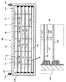
具体的には、図2に示すように、上流側のオーブンタワー(TB)44では、搬入用パスユニット(PASS)50の上に脱水ベーク用の加熱ユニット(DHP)51,52およびアドヒージョンユニット(AD)54が多段に積み重ねられる。ここで、搬入用パスユニット(PASS)50は、スクラバ洗浄ユニット(SCR)42から洗浄処理の済んだ基板Gを受け取るためのスペースを提供する。また、下流側のオーブンタワー(TB)48では、搬出用パスユニット(PASS)58の上に冷却ユニット(COL)59,60およびアドヒージョンユニット(AD)62が多段に積み重ねられる。ここで、搬出用パスユニット(PASS)58は、塗布プロセス部28側へレジスト塗布処理を受けるべき基板Gを手渡す(または送り出す)ためのスペースを提供する。両オーブンタワー(TB)44,48の最下段には、当該オーブンタワー(TB)44,48内の各部に所要の用力または制御信号を供給するための用力供給部または制御部を収容するユーティリティ・ユニット(UTL)56,64が設けられている。
【0024】
上流側の搬入用パスユニット(PASS)50の室内には、スクラバ洗浄ユニット(SCR)42の水平搬送路(図示せず)が引き込まれている。さらに、搬送路上の基板を水平姿勢で持ち上げるための昇降可能なリフトピン(図示せず)が設けられることもある。各熱処理系のユニット(DHP)51,52、(AD)54,62、(COL)59,60の室内には、基板Gを水平に載置して加熱する熱板(図示せず)や該熱板上で基板Gの受け渡しを行うための昇降可能なリフトピン(図示せず)等が設けられている。下流側の搬出用パスユニット(PASS)58の室内には、隣の塗布プロセス部28へ基板Gを搬出可能に構成された搬送路、あるいは塗布プロセス部28側の搬送手段からアクセス可能に構成された基板支持部(図示せず)等が設けられている。
【0025】
この実施形態では、上流側および/または下流側の両オーブンタワー(TB)44,48の最上段に、非常時に基板Gを留め置いて保管するためのバッファユニット(BUF)66が設けられている。このバッファユニット(BUF)66の具体的な構成および作用は後に説明する。
【0026】
図2において、搬送機構46は、鉛直方向に延在するガイドレール68に沿って昇降移動可能な昇降搬送体70と、この昇降搬送体70上でθ方向に回転または旋回可能な旋回搬送体72と、この旋回搬送体72上で基板Gを支持しながら前後方向に進退または伸縮可能な搬送アームまたはピンセット74とを有している。昇降搬送体70を昇降駆動するための駆動部76が垂直ガイドレール68の基端側に設けられ、旋回搬送体72を旋回駆動するための駆動部78が昇降搬送体70に取り付けられ、搬送アーム74を進退駆動するための駆動部80が回転搬送体72に取り付けられている。各駆動部76,78,80はたとえば電気モータ等で構成されてよい。
【0027】
かかる構成の搬送機構46は、図示しないコントローラの制御の下で、高速に昇降ないし旋回運動して両隣のオーブンタワー(TB)44,48の中の任意のユニットにアクセスして基板Gの搬入出を行うことが可能であり、補助搬送空間38側のシャトル40とも基板Gを受け渡しできるようになっている。
【0028】
第1の熱的処理部26の下流側に隣接する塗布プロセス部28は、図1に示すように、レジスト塗布ユニット(CT)82、減圧乾燥ユニット(VD)84およびエッジリムーバ・ユニット(ER)86をプロセスラインAに沿って一列に配置している。図示省略するが、塗布プロセス部28内には、これら3つのユニット(CT)82、(VD)84、(ER)86に基板Gを工程順に1枚ずつ搬入・搬出するための搬送装置(図示せず)が設けられており、各ユニット(CT)82、(VD)84、(ER)86内では基板1枚単位で各処理が行われるようになっている。なお、該搬送装置は、第1の熱的処理部26の搬出用パスユニット(PASS)58にもアクセス可能になっている。
【0029】
塗布プロセス部28の下流側に隣接する第2の熱的処理部30は、上記第1の熱的処理部26と同様の構成を有しており、両プロセスラインA,Bの間に縦型の搬送機構90を設け、プロセスラインA側(最後尾)に一方のオーブンタワー(TB)88を設け、プロセスラインB側(先頭)に他方のオーブンタワー(TB)92を設けている。
【0030】
図示省略するが、たとえば、プロセスラインA側のオーブンタワー(TB)88には、塗布プロセス部28から基板Gを受け取るための搬入用パスユニット(PASS)が設けられるとともに、この搬入用パスユニット(PASS)の上にプリベーク用の加熱ユニット(PREBAKE)がたとえば3段積み重ねられてよい。また、プロセスラインB側のオーブンタワー(TB)92には、現像プロセス部32へ基板Gを渡すための搬出用パスユニット(PASS)が設けられるとともに、この搬出用パスユニット(PASS)の上に冷却ユニット(COL)がたとえば1段重ねられ、その上にプリベーク用の加熱ユニット(PREBAKE)がたとえば2段積み重ねられてよい。両オーブンタワー(TB)88,92の最下段にはそれぞれユーティリティ・ユニット(UTL)が設けられてよい。この第2の熱的処理部30においても、オーブンタワー(TB)88,92の双方または片方の最上段に、非常時に基板Gを留め置いて保管するためのバッファユニット(BUF)が配置されてよい。
【0031】
搬送機構90は、図示しないコントローラの制御の下で、高速に昇降ないし旋回運動して両オーブンタワー(TB)88,92の中の任意のユニットにアクセスして基板Gの搬入出を行うことが可能であり、両側のパスユニット(PASS)を介して塗布プロセス部28および現像プロセス部32と基板Gを1枚単位で受け渡しできるだけでなく、補助搬送空間38内のシャトル40や後述するインタフェースステーション(I/F)18とも基板Gを1枚単位で受け渡しできるようになっている。
【0032】
下流部のプロセスラインBにおいて、現像プロセス部32は、基板Gを水平姿勢で搬送しながら一連の現像処理工程を行う、いわゆる平流し方式の現像ユニット(DEV)94を含んでいる。
【0033】
現像プロセス部32の下流側には脱色プロセス部34を挟んで第3の熱的処理部36が配置される。脱色プロセス部34は、基板Gの被処理面にi線(波長365nm)を照射して脱色処理を行うためのi線UV照射ユニット(i−UV)96を備えている。
【0034】
第3の熱的処理部36は、上記第1の熱的処理部26や第2の熱的処理部30と同様の構成を有しており、プロセスラインBに沿って縦型の搬送機構100とその前後両側に一対のオーブンタワー(TB)98,102を設けている。
【0035】
図示省略するが、たとえば、上流側のオーブンタワー(TB)98には、脱色プロセス部34から基板Gを受け取るための搬入用パスユニット(PASS)が設けられるとともに、このパスユニット(PASS)の上にポストベーキング用の加熱ユニット(POBAKE)がたとえば3段積み重ねられてよい。また、下流側のオーブンタワー(TB)102には、カセットステーション(C/S)14へ基板Gを渡すための搬出用パスユニット(PASS)が設けられるとともに、このパスユニット(PASS)の上に冷却用のパス・クーリングユニット(PASS・COL)が1段重ねられ、その上にポストベーキング用の加熱ユニット(POBAKE)が2段積み重ねられてよい。両オーブンタワー(TB)98,102の最下段にはそれぞれユーティリティ・ユニット(UTL)が設けられてよい。
【0036】
この第3の熱的処理部36においても、両オーブンタワー(TB)98,102の双方または片方の最上段に、非常時に基板Gを留め置いて保管するためのバッファユニット(BUF)が配置されてよい。
【0037】
搬送機構100は、図示しないコントローラの制御の下で、高速に昇降ないし旋回運動して両オーブンタワー(TB)98,102の中の任意のユニットにアクセス可能であり、両側のパスユニット(PASS)およびパス・クーリングユニット(PASS・COL)を介してそれぞれi線UV照射ユニット(i−UV)96およびカセットステーション(C/S)14と基板Gを1枚単位で受け渡しできるだけでなく、補助搬送空間38内のシャトル40とも基板Gを1枚単位で受け渡しできるようになっている。
【0038】
インタフェースステーション(I/F)18は、隣接する露光装置12と基板Gのやりとりを行うための搬送装置104を有し、その周囲にバッファ・ステージ(BUFS)106、エクステンション・クーリングステージ(EXT・COL)108および周辺装置110を配置している。バッファ・ステージ(BUFS)106には定置型のバッファカセット(図示せず)が置かれる。エクステンション・クーリングステージ(EXT・COL)108は、冷却機能を備えた基板受け渡し用のステージであり、プロセスステーション(P/S)16側と基板Gをやりとりする際に用いられる。周辺装置110は、たとえばタイトラー(TITLER)と周辺露光装置(EE)とを上下に積み重ねた構成であってよい。搬送装置104は、基板Gを保持できる手段たとえば搬送アーム104aを有し、隣接する露光装置12や各ユニット(BUFS)106、(EXT・COL)108、(TITLER/EE)110と基板Gの受け渡しを行えるようになっている。
【0039】
図3に、この塗布現像処理システムにおける正常時の処理の手順を示す。先ず、カセットステーション(C/S)14において、搬送機構22が、ステージ20上の所定のカセットCの中から1つの基板Gを取り出し、プロセスステーション(P/S)16の洗浄プロセス部24のエキシマUV照射ユニット(e−UV)41に搬入する(ステップS1)。
【0040】
エキシマUV照射ユニット(e−UV)41内で基板Gは紫外線照射による乾式洗浄を施される(ステップS2)。この紫外線洗浄では主として基板表面の有機物が除去される。紫外線洗浄の終了後に、基板Gは、カセットステーション(C/S)14の搬送機構22によって洗浄プロセス部24のスクラバ洗浄ユニット(SCR)42へ移される。
【0041】
スクラバ洗浄ユニット(SCR)42では、上記したように基板Gをコロ搬送またはベルト搬送により水平姿勢でプロセスラインA方向に平流しで搬送しながら基板Gの表面にブラッシング洗浄やブロー洗浄を施すことにより、基板表面から粒子状の汚れを除去する(ステップS3)。そして、洗浄後も基板Gを平流しで搬送しながらリンス処理を施し、最後にエアーナイフ等を用いて基板Gを乾燥させる。
【0042】
スクラバ洗浄ユニット(SCR)42内で洗浄処理の済んだ基板Gは、第1の熱的処理部26の上流側オーブンタワー(TB)44内の搬入用パスユニット(PASS)50に搬入される。
【0043】
第1の熱的処理部26において、基板Gは搬送機構46により所定のシーケンスで熱処理系のユニットを回される。たとえば、基板Gは、最初に搬入用パスユニット(PASS)50から加熱ユニット(DHP)51,52の1つに移され、そこで脱水処理を受ける(ステップS4)。次に、基板Gは、冷却ユニット(COL)59,60の1つに移され、そこで一定の基板温度まで冷却される(ステップS5)。しかる後、基板Gはアドヒージョンユニット(AD)54,62の1つに移され、そこで疎水化処理を受ける(ステップS6)。この疎水化処理の終了後に、基板Gは冷却ユニット(COL)59,60の1つで一定の基板温度まで冷却される(ステップS7)。最後に、基板Gは下流側オーブンタワー(TB)48の搬出用パスユニット(PASS)58に移される。
【0044】
このように、第1の熱的処理部26内では、基板Gが、搬送機構46を介して上流側のオーブンタワー(TB)44と下流側のオーブンタワー(TB)48との間で任意に行き来できるようになっている。なお、第2および第3の熱的処理部30,36でも同様の基板搬送動作を行えるようになっている。
【0045】
第1の熱的処理部26で上記のような一連の熱的または熱系の処理を受けた基板Gは、オーブンタワー(TB)48内の搬出用パスユニット(PASS)58から下流側隣の塗布プロセス部28のレジスト塗布ユニット(CT)82へ移される。
【0046】
基板Gはレジスト塗布ユニット(CT)82でたとえばスピンコート法により基板上面(被処理面)にレジスト液を塗布され、直後に下流側隣の減圧乾燥ユニット(VD)84で減圧による乾燥処理を受け、次いで下流側隣のエッジリムーバ・ユニット(ER)86で基板周縁部の余分(不要)なレジストを取り除かれる(ステップS8)。
【0047】
上記のようなレジスト塗布処理を受けた基板Gは、エッジリムーバ・ユニット(ER)86から隣の第2の熱的処理部30の上流側オーブンユニット(TB)88に属する搬入用パスユニット(PASS)に受け渡される。
【0048】
第2の熱的処理部30内で、基板Gは、搬送機構90により所定のシーケンスで熱処理ユニットを回される。たとえば、基板Gは、最初に該パスユニット(PASS)から加熱ユニット(PREBAKE)の1つに移され、そこでレジスト塗布後のベーキングを受ける(ステップS9)。次に、基板Gは、冷却ユニット(COL)の1つに移され、そこで一定の基板温度まで冷却される(ステップS10)。しかる後、基板Gは下流側オーブンタワー(TB)92内の搬出用パスユニット(PASS)を経由して、あるいは経由せずにインタフェースステーション(I/F)18側のエクステンション・クーリングステージ(EXT・COL)108へ受け渡される。
【0049】
インタフェースステーション(I/F)18において、基板Gは、エクステンション・クーリングステージ(EXT・COL)108から周辺装置110の周辺露光装置(EE)に搬入され、そこで基板Gの周辺部に付着するレジストを現像時に除去するための露光を受けた後に、隣の露光装置12へ送られる(ステップS11)。
【0050】
露光装置12では基板G上のレジストに所定の回路パターンが露光される。そして、パターン露光を終えた基板Gは、露光装置12からインタフェースステーション(I/F)18に戻されると(ステップS11)、先ず周辺装置110のタイトラー(TITLRER)に搬入され、そこで基板上の所定の部位に所定の情報が記される(ステップS12)。しかる後、基板Gはエクステンション・クーリングステージ(EXT・COL)108に戻される。インタフェースステーション(I/F)18における基板Gの搬送および露光装置12との基板Gのやりとりは搬送装置104によって行われる。
【0051】
プロセスステーション(P/S)16では、第2の熱的処理部30において搬送機構90がエクステンション・クーリングステージ(EXT・COL)108より露光済の基板Gを受け取り、プロセスラインB側のオーブンタワー(TB)92内の搬出用パスユニット(PASS)を介して現像プロセス部32へ受け渡す。
【0052】
現像プロセス部32では、該オーブンタワー(TB)92内のパスユニット(PASS)から受け取った基板Gを現像ユニット(DEV)94に搬入する。現像ユニット(DEV)94において基板GはプロセスラインBの下流に向って平流し方式で搬送され、その搬送中に現像、リンス、乾燥の一連の現像処理工程が行われる(ステップS13)。
【0053】
現像プロセス部32で現像処理を受けた基板Gは下流側隣の脱色プロセス部34へ搬入され、そこでi線照射による脱色処理を受ける(ステップS14)。脱色処理の済んだ基板Gは、第3の熱的処理部36の上流側オーブンタワー(TB)98内の搬入用パスユニット(PASS)に受け渡される。
【0054】
第3の熱的処理部(TB)98において、基板Gは、最初に該パスユニット(PASS)から加熱ユニット(POBAKE)の1つに移され、そこでポストベーキングを受ける(ステップS15)。次に、基板Gは、下流側オーブンタワー(TB)102内のパスクーリング・ユニット(PASS・COL)に移され、そこで所定の基板温度に冷却される(ステップS16)。第3の熱的処理部36における基板Gの搬送は搬送機構100によって行われる。
【0055】
カセットステーション(C/S)14側では、搬送機構22が、第3の熱的処理部36のパスクーリング・ユニット(PASS・COL)から塗布現像処理の全工程を終えた基板Gを受け取り、受け取った基板Gをいずれか1つのカセットCに収容する(ステップS1)。
【0056】
上記のように、この塗布現像処理システムでは、各部(特に処理系の各部)が正常に動作している限りは、カセットステーション(C/S)14からプロセスステーション(P/S)18側に渡された基板Gが、プロセスラインA,Bに沿ってシステム内の各部を移送または転送されながら所要の各処理(ステップS2〜S16)を順次受けて、一定時間内にカセットステーション(C/S)14へ回送されるようになっている。
【0057】
しかしながら、システム内の何処かで、特に処理部で故障その他の障害が発生したときは、プロセスフローの上流側からその障害の発生した処理部へ基板Gを転送または搬入できなくなる。もっとも、下流側ではライン上の基板Gに対して残りの全処理を完遂することができる。
【0058】
そのようにシステム内の何処かでプロセスフローが停止し、または滞った場合、この実施形態では障害発生箇所よりも上流側に配備されているバッファユニット(BUF)が基板Gの一時的な留め置きないし保管に利用される。
【0059】
たとえば、塗布プロセス部28内で障害が発生して該プロセス部28への基板搬入ができなくなった場合を例にとる。この場合、第1の熱的処理部26に配備されているバッファユニット(BUF)が基板Gの留め置きに用いられる。
【0060】
より詳細には、塗布プロセス部28内で障害が発生すると、カセットステーション(C/S)14から洗浄プロセス部24に対して、特にスクラバ洗浄ユニット(SCR)42に対して基板Gの新規搬入が止められる。この時、スクラバ洗浄ユニット(SCR)42では、水平搬送路上で複数枚たとえば5枚の基板Gを所定間隔で一列に搬送しながら平流し方式の基板洗浄処理を行っており、平流し搬送を止めたならばそれらの基板Gを洗浄不良品にしてしまう。
【0061】
この実施形態では、そのような洗浄不良品を出さぬように、スクラバ洗浄ユニット(SCR)42においては平流し搬送中の基板Gに対する洗浄処理を完遂させる。したがって、スクラバ洗浄ユニット(SCR)42から第1の熱的処理部26に対しては、正常時と同じサイクルないしタイミングで洗浄済みの基板Gが次々と搬入される。
【0062】
第1の熱的処理部26において、各基板Gは、可能な限り通常と同じシーケンスで熱的処理を受けてからバッファユニット(BUF)66に格納される。
【0063】
より詳細には、スクラバ洗浄ユニット(SCR)42より上流側のパスユニット(PASS)50に搬入された各基板Gは、最初に加熱ユニット(DHP)51,52の1つで脱水処理を受けてから(ステップS4)、冷却ユニット(COL)59,60の1つで一定の基板温度まで冷却され(ステップS5)、しかる後にアドヒージョンユニット(AD)54,62の1つで疎水化処理を受ける(ステップS6)。ここまでの一連の熱的処理(ステップS4→S5→S6)は通常と変わらない。
【0064】
しかし、疎水化処理の後、基板Gは、通常であれば冷却ユニット(COL)54,62の1つで基板温度一定化の熱処理(ステップS7)を受けて、次に搬出用パスユニット(PASS)58へ送られるべきところ、この非常事態の場面では冷却ユニット(COL)59,60や搬出用パスユニット(PASS)58への転送をキャンセルしてバッファユニット(BUF)66に転送される。
【0065】
ここで、基板温度一定化の熱処理(ステップS7)を敢えて省くのは、この熱処理がその直後に塗布プロセス部28においてレジスト塗布処理が実行されることを前提とした前処理であることと、搬送機構46のスループットないし各部間のタクト調整上の理由からである。
【0066】
この種の塗布現像処理システムでは、一般に、同一機能の熱処理ユニットを複数(N個)設けて、それらN個の熱処理ユニットで同一サイクルタイムの熱処理を一定の時間ずらして並行して行わせることにより、熱処理部全体のタクトを1/Nに短縮して、前工程および後工程の処理タクトに合せるようにしている。たとえば、この実施形態において、スクラバ洗浄ユニット(SCR)42における洗浄処理タクトが60秒であるところ、第1の熱的処理部26における各熱処理ユニット(AD),(DHP),(COL)のサイクルタイムが100秒前後である場合は、図2のように各熱処理ユニット(AD),(DHP),(COL)をそれぞれ2台設けて50秒前後の時間差で並列稼動させることにより、熱処理全体ないし各部のタクトを洗浄処理タクトに合せることができる。
【0067】
このようなマルチユニット方式の熱的処理部26において、搬送機構46は殆ど間断なく各熱処理ユニットを一定のサイクルで巡回するように目一杯のスケジュールで忙しく動作しており、非常事態であるからといって通常の巡回動作の中に基板Gをバッファユニット(BUF)66へ転送する動作を割り込ませられるほどの余裕はないのが普通である。この実施形態では、上記のように最終段の熱処理工程である基板温度一定化の熱処理(ステップS7)をキャンセルすることで、搬送スループット上またはタクト上の支障を来すことなくバッファユニット(BUF)66への基板格納動作を実現している。
【0068】
上記のようにして、障害発生時にスクラバ洗浄ユニット(SCR)42内で洗浄処理を受けていた最中の基板Gの全部(たとえば5枚)が何ら滞ることなく正常に平流しの洗浄処理を施され、かつ次段の第1の熱的処理部26においても実質的に通常と変わらない一連の熱処理を受けてからバッファユニット(BUF)66に格納される。
【0069】
この実施形態では、非常時、特に本例のようにプロセスフローの下流側への基板転送を止めるときは、上記のように最終段の熱処理工程である基板温度一定化の熱処理(ステップS7)と搬出用パスユニット(PASS)58への転送とをキャンセルするので、バッファユニット(BUF)66に基板Gを格納する搬送工程を増やしても、搬送機構46の負担は重くはならない。むしろ搬送機構46は、上記のように正常時の方が、目一杯のスケジュールで各熱処理ユニットを忙しく巡回して動作する。
【0070】
この点、この実施形態では、バッファユニット(BUF)66がオーブンタワー(TB)44,48の最上段に配置されている。このため、バッファユニット(BUF)66にアクセスする必要のない正常時において、搬送機構46は、バッファユニット(BUF)66の下に集約配置された熱処理系ユニット(AD)54,62、(DHP)51,52、(COL)59,60および基板搬入出用のパスユニット(PASS)50,58を必要最小限の移動範囲で巡回して所要の搬送スケジュールを効率良くこなすことができる。
【0071】
なお、この実施形態では、上流側に接続するパスユニット(PASS)50と下流側に接続するパスユニット(PASS)58とが搬送機構46を挟んで互いに独立しており、上流側の搬入用パスユニット(PASS)50ないし搬送路と下流側の搬出用パスユニット(PASS)58ないし搬送路とを同じ高さに設定することも異なる高さに設定することも自由である。
【0072】
ところで、第1の熱的処理部26内でも何処かで故障その他の障害が発生する場合がある。たとえば、アドヒージョンユニット(AD)54で熱板が故障して使用不可になった場合を例にとる。
【0073】
この場合、他方のアドヒージョンユニット(AD)62の単独または片肺運転に切り換えることで、タクトが長く(遅く)なるもののシステムの継続運転は可能である。しかし、第1の熱的処理部26においてタクトを切り換えた直後も、上流側のスクラバ洗浄ユニット(SCR)42からは障害発生時に平流し搬送中の基板Gの全部を一掃するまで通常のタクトで洗浄済みの基板Gが搬入されてくる。この場面でも、第1の熱的処理部26では、スクラバ洗浄ユニット(SCR)42から受け取った基板Gを熱処理の前または合間にバッファユニット(BUF)66に一時的に留め置くことで、タクトの補償または調整を行うことができる。
【0074】
第2および第3の熱的処理部30,36でも、第1の熱的処理部26と同様な機能および作用が得られる。これらの熱的処理部26,30,36間で上記のような基板の留め置きを連携させることも独立させることも可能である。バッファユニット(BUF)は上記のようなシステム障害が発生した場合に限らず、必要に応じて種々の場面で活用されてよい。
【0075】
以下に、この実施形態におけるオーブンタワー(TB)およびバッファユニット(BUF)66の具体的な構成と作用を説明する。
【0076】
図4に、この実施形態におけるオーブンタワー(TB)たとえば44の具体的な構成を示す。このオーブンタワー(TB)44は、ハウジング型またはラック型のユニット収納筐体112の中に熱処理系ユニット(AD)54,(DHP)51,52、搬入用パスユニット(PASS)50およびユーティリティ・ユニット(UTL)56を着脱可能に多段に収納し、ユニット収納筐体112の上にバッファユニット(BUF)66を分離可能に配置する。ユニット収納筐体112の底部または脚部114は定置型に構成されてもよく、あるいはキャスタを有する可動型に構成されてもよい。ユニット収納筐体112内には、各ユニットを筐体正面(搬送機構46と対向する面)以外の面(背面または側面)から水平に出し入れするためのスライド機構(図示せず)が設けられてよい。ユニット収納筐体112の正面には必要に応じて各ユニット毎に開閉扉またはシャッタ116が設けられてよい。
【0077】
このように、この実施形態のオーブンタワー(TB)44では、特に用力を必要としないバッファユニット(BUF)66がタワー最上段に配置(隔離)されるので、ユニット収納筐体112側では熱処理系ユニット(AD)54,(DHP)51,52や搬入用パスユニット(PASS)50に対する用力ライン(配管、電気ケーブル等)の引き回しを効率よく行うことができる。他のオーブンタワー(TB)48,88,92,98,102でも同様である。
【0078】
図5に、この実施形態におけるバッファユニット(BUF)66内部の構成を示す。このバッファユニット(BUF)66は、基板Gを複数枚多段に収納可能な基板収納空間SPを与えるバッファ筐体120と、このバッファ筐体120内で基板Gを1枚ずつ載置するためにバッファ筐体102の基板収納空間SPを水平に横断して設けられる複数の水平支持板122と、基板Gをピン先端124aで支持するために各々の水平支持板122上に離散的に設けられる複数の支持ピン124とを有している。
【0079】
バッファ筐体120は、たとえばアルミニウムで形成され、筐体正面つまり搬送機構46と対向する面は開口されてよく、この正面開口を通って搬送機構46の搬送アーム74がバッファ筐体120内に自由に出入りできるようになっている。バッファ筐体120から基板Gを搬出するときは、図示のように、搬送機構46が搬送アーム74を目的の基板Gと該当支持板122との間に水平に挿入し、次いで搬送アーム74を所定の高さだけ水平に持ち上げて該当の支持ピン124から基板Gを搬送アーム74に受け取り(移載し)、次いで搬送アーム74を旋回搬送体72(図2)側に引いて基板Gをバッファ筐体120から取り出す。バッファ筐体120に基板Gを搬入するときは、上記搬出動作を時間的に巻き戻すような逆のハンドリングが行われる。なお、搬送アーム74の上面には、基板Gを真空吸着力で保持するためのバキュームパッド(図示せず)が設けられてよい。
【0080】
水平支持板122は、たとえばアルミニウム板からなり、バッファ筐体120内でほぼ水平に棚状に架け渡され、左右両側壁に固定取付される。支持ピン124は、基板Gと直接接触するピン先端部124aは樹脂が好ましく、ピン本体部はたとえばアルミニウムで形成されてよい。水平支持板122上における支持ピン124の配置パターンは、搬送アーム74の出入りを妨げずに基板Gをほぼ水平に支持できればよく、たとえば格子状の配置パターンが好ましい。
【0081】
このバッファユニット(BUF)66においては、上記の構成により、バッファ筐体120内で各基板Gが支持ピン124を介して各支持板122上に撓みの少ない水平姿勢で載置されるので、搬送手段の出入りないし基板ハンドリングを容易にし、ひいては基板収納空間のスペース効率を高めることができる。
【0082】
このバッファユニット(BUF)66の基板収納容量は、図示の例では5(枚)であるが、任意の容量に選択または変更できる。基板収納容量を大きくするほど、バッファユニット(BUF)66の高さサイズは大きくなる。この実施形態では、バッファユニット(BUF)66がユニット収納筐体112の上に配置されるため、バッファユニット(BUF)66の基板収納容量または高さサイズによってユニット収納筐体112ないしその中のユニット(50〜56)のレイアウトが影響を受けることはない。しかも、オーブンタワー(TB)の出荷時には、バッファユニット(BUF)66をユニット収納筐体112からいったん切り離して移送できるので、バッファユニット(BUF)66とユニット収納筐体112がそれぞれ単独で建物内や道路上の高さ制限をクリアできればよく、高さ制限を優に越えるオーブンタワー(TB)も問題なく構築することができる。もちろん、バッファユニット(BUF)66をユニット収納筐体112から切り離すに際して、ユニット収納筐体112側の用力系統(特に配管や配線類)をいじる必要もない。なお、図5に示すように、バッファユニット(BUF)66の上面には、このユニットをクレーンで吊るためのリング型の金具126が取り付けられている。
【0083】
上記したようなバッファユニット(BUF)66の構成は、他のオーブンタワー(TB)48,88,92,98,102に設けられるバッファユニット(BUF)にも適用できる。
【0084】
この実施形態において、バッファユニット(BUF)は正面の開口した筐体で構成できるが、開閉扉またはシャッタを設けることも可能である。また、室内に不活性ガスたとえば窒素ガスの雰囲気を形成することも可能である。その場合、たとえばユニット筐体の後背部から窒素ガスを導入し、多孔板を介して窒素ガスの均一な流れと雰囲気を形成してよい。上記実施形態では1つのバッファユニット(BUF)に基板Gを複数枚収納する構成としたが、1枚単位で収納するバッファユニットを多段に積層配置する構成も可能である。上記実施形態では処理ユニット(AD,DHP,COL等)の全部をパスユニット(PASS)の上に配置したが、一部をパスユニット(PASS)の下に配置することも可能である。また、オーブンタワーに熱処理系以外の処理ユニットを含む構成や、熱処理系以外の処理ユニットだけでオーブンタワーと同様の多段ユニット部を構成することも可能である。
【0085】
本発明の処理システムは上記したような塗布現像処理システムに適用して好適であるが、システム構成やシステム要素において種々の変形が可能であり、たとえば成膜装置やエッチング装置等を含むインライン型システムにも適用可能である。本発明における被処理基板は、被処理基板はLCD基板に限るものではなく、フラットパネルディスプレイ用の各種基板や、半導体ウエハ、CD基板、フォトマスク、プリント基板等の各種の被処理基板が含まれる。
【0086】
【発明の効果】
以上説明したように、本発明の処理システムによれば、システム内の一部でプロセスフローが滞っても上流側の処理部あるいは被処理基板の受ける影響を最小限に食い止めることが可能であり、処理効率および品質の向上をはかれるとともに、そのようなセーフティ機能を効率的かつ取扱いに便利なレイアウトで実現することができる。
【図面の簡単な説明】
【図1】本発明の実施形態による塗布現像処理システムの構成を示す平面図である。
【図2】上記塗布現像処理システムにおける熱的処理部の構成を示す側面図である。
【図3】上記塗布現像処理システムにおける正常時の処理の手順を示すフローチャートである。
【図4】実施形態におけるオーブンタワー(TB)の具体的な構成を示す略側面図である。
【図5】実施形態におけるバッファユニット(BUF)内部の構成を示す縦断面図である。
【符号の説明】
10 塗布現像処理システム
14(C/S) カセットステーション
16(P/S) プロセスステーション
18(I/F) インタフェースステーション
24 洗浄プロセス部
26 第1の熱的処理部
28 塗布プロセス部
30 第2の熱的処理部
32 現像プロセス部
36 第3の熱的処理部
42(SCR) スクラバ洗浄ユニット
44,48(TB) オーブンタワー(多段ユニット部)
46 搬送機構
51,52(DHP) 加熱ユニット
54,62(AD) アドヒージョンユニット
59,60 冷却ユニット
66 バッファユニット
74 搬送アーム
120 バッファ筐体
122 水平支持板
124 支持ピン
124a ピン先端部[0001]
TECHNICAL FIELD OF THE INVENTION
The present invention relates to a processing system in which a large number of processing units for performing a series of processing on a substrate to be processed are arranged in a substantially horizontal direction in the order of a process flow.
[0002]
[Prior art]
Recently, in a resist coating and developing processing system for LCD (Liquid Crystal Display) manufacturing, in order to cope with an increase in the size of the LCD substrate, the LCD substrate is horizontally moved on a transport path in which transport members such as transport rollers are laid horizontally. Equipped with a so-called flat-flow type cleaning processing unit and development processing unit that performs cleaning processing or development processing while transporting, and the entire system is generally arranged in the process flow order according to such a flat-flow processing unit. 2. Description of the Related Art A system configuration or layout that serially arranges data on a horizontal line has been widely used (for example, see Patent Document 1).
[0003]
In the processing system as described above, the thermal processing unit for performing thermal processing associated with the flat-flow type liquid processing is an oven in which a single-wafer type oven unit including a hot plate is collectively arranged in multiple stages. Two towers are installed in one set at the beginning or end of each flat flow line, and one of the oven towers has a loading path unit for loading the substrates from the upstream processing section in the process flow. The other oven tower is provided with an unloading pass unit for unloading the substrate to the processing section on the downstream side. Then, an ascending / descending / rotating transfer robot arranged between the two oven towers transfers the substrate in a predetermined cyclic sequence between the pass unit and the oven unit.
[0004]
[Patent Document 1]
JP 2003-59824 A
[0005]
[Problems to be solved by the invention]
However, in the processing system as described above, even if the processing is stopped or stopped at one location due to the occurrence of a failure or other failure, or due to the necessity for maintenance, all the processing units located on the upstream side of the process flow are stopped. Is affected, and each process must be stopped or slowed down.
[0006]
In this case, in the flat-flow processing unit, in order for the normal operation of various tools arranged along the horizontal transport path to sequentially perform a series of processing at a certain timing on a substrate passing by the downstream side, If the substrate on the horizontal transport path is retained due to the effect of the processing step being delayed in the processing unit, the processing content or the processing result may not be as set, and the yield may be reduced.
[0007]
The present invention has been made in view of the problems of the related art, and has been made to minimize the influence of an upstream processing unit or a substrate to be processed even when a process flow is delayed in a part of a system. It is an object to provide a processing system having a safety function.
[0008]
Another object of the present invention is to provide a processing system that realizes the above-described safety function with a layout that is efficient and convenient for handling.
[0009]
[Means for Solving the Problems]
In order to achieve the above object, a processing system according to the present invention includes a first transfer unit for receiving a substrate to be processed from a first processing unit on an upstream side in a process flow, and a second transfer unit on a downstream side in a process flow. A second delivery unit for delivering the substrate to the processing unit, and one or more of the first delivery unit and / or the second delivery unit which are stacked and arranged in a multi-stage manner on or under each of the second delivery units And a multi-stage unit section including the first transfer unit and / or the second transfer unit and the processing unit for temporarily holding and storing the substrate. A buffer unit and the first and second transfer units, the processing unit, and the buffer unit. And a conveying means for conveying the plate.
[0010]
In the processing system of the present invention, a typical mode is that the transfer means buffers the substrate received by the first transfer unit when the transfer of the substrate to one of the processing units or the second processing unit is impossible. This is a mode of storing in one of the units. In this case, by storing the substrate in the buffer unit after completing the processing of one or more steps before the processing to be performed in the processing unit or the second processing unit which cannot be carried in, the process flow is stagnated. In addition, a decrease in throughput can be minimized.
[0011]
In the processing system of the present invention, the first processing unit performs a series of processes on a first transport path for transporting the substrate in a substantially horizontal posture in a horizontal direction, and a substrate transported on the first transport path. In the configuration including the first processing means to be applied (flat flow system), the buffer unit is particularly useful, and it is possible to avoid undesired interruption of the flat flow process in the first processing unit. Needless to say, a second transport path for the second processing unit to transport the substrate in the horizontal direction in a substantially horizontal posture, and a second processing for performing a series of processes on the substrate transported on the second transport path It is also possible to adopt a configuration that includes means (flat flow system).
[0012]
In the system configuration of the present invention, the buffer unit normally used in an emergency is arranged at the top of the multi-stage unit. Therefore, when the buffer unit is not used, the transport unit does not need to access the buffer unit. Of course, it is not necessary to pass by the side, and the transfer schedule can be efficiently handled in the area where the processing units are collectively arranged. In addition, since the buffer unit that does not particularly require utility is arranged at the uppermost stage of the multi-stage unit portion, it is possible to efficiently route utility lines (piping, electric cables, etc.) to the processing unit. Further, since the height size of the buffer unit arranged at the top does not affect the layout on the processing unit side, the substrate storage capacity of the buffer unit can be arbitrarily set. Further, when the multi-stage unit is shipped, the buffer unit and the processing unit side are temporarily separated from each other, so that it is possible to advantageously cope with height restrictions and the like.
[0013]
In the processing system of the present invention, preferably, a utility supply unit for supplying a predetermined utility to the processing unit may be arranged at the lowermost stage of the multi-stage unit. In a preferred aspect of the buffer unit, a housing that provides a substrate storage space in which a plurality of substrates can be stored in multiple stages and a substrate storage space of the housing for mounting the substrates one by one are provided. The configuration includes a plurality of support plates and a plurality of support pins discretely provided on each support plate to support the substrate at the tip of the pin. According to such a configuration, since each substrate is placed on each support plate via the support pins in the housing in a horizontal posture with little bending, it is easy to enter / exit the transport means or to handle the substrate, and thus, the space for the substrate storage space is obtained. Space efficiency can be increased.
[0014]
A preferred mode of the transporting means is a vertically movable carrier capable of vertically moving up and down, a rotating carrier capable of rotating around a vertical axis on the vertically movable carrier, and a horizontal surface supporting the substrate on the rotating carrier. And a transfer arm that can expand and contract in the front-rear direction. In such a configuration, the transporting means can move up and down or swing to access an arbitrary unit in the multi-stage unit on both sides to carry in and out the substrate.
[0015]
BEST MODE FOR CARRYING OUT THE INVENTION
Hereinafter, preferred embodiments of the present invention will be described with reference to the accompanying drawings.
[0016]
FIG. 1 shows a coating and developing system to which the present invention can be applied. The coating and developing
[0017]
In this coating and developing
[0018]
The cassette station (C / S) 14 is a cassette loading / unloading port of the
[0019]
The process station (P / S) 16 arranges each processing unit on a pair of parallel and opposite lines A and B extending in the system longitudinal direction (X direction) in the order of process flow or process. More specifically, an upstream process line A from the cassette station (C / S) 14 to the interface station (I / F) 18 has a
[0020]
An
[0021]
In the upstream process line A, the
[0022]
The first
[0023]
Specifically, as shown in FIG. 2, in the oven tower (TB) 44 on the upstream side, heating units (DHP) 51 and 52 for dehydration baking and adhesion The units (AD) 54 are stacked in multiple stages. Here, the carry-in pass unit (PASS) 50 provides a space for receiving the cleaned substrate G from the scrubber cleaning unit (SCR) 42. In the downstream oven tower (TB) 48, cooling units (COL) 59 and 60 and an adhesion unit (AD) 62 are stacked on a carry-out path unit (PASS) 58 in multiple stages. Here, the unloading pass unit (PASS) 58 provides a space for handing over (or sending out) the substrate G to be subjected to the resist coating process to the
[0024]
The horizontal transport path (not shown) of the scrubber cleaning unit (SCR) 42 is drawn into the room of the carry-in pass unit (PASS) 50 on the upstream side. Further, a lift pin (not shown) that can lift and lower the substrate on the transport path in a horizontal posture may be provided. In the chambers of the heat treatment units (DHP) 51, 52, (AD) 54, 62, (COL) 59, 60, a hot plate (not shown) for mounting and heating the substrate G horizontally and A lift pin (not shown) that can move up and down for transferring the substrate G on the hot plate is provided. In the room of the unloading pass unit (PASS) 58 on the downstream side, a transport path configured to be able to unload the substrate G to the adjacent
[0025]
In this embodiment, a buffer unit (BUF) 66 for holding and storing the substrate G in an emergency is provided at the uppermost stage of both the upstream and / or downstream oven towers (TB) 44, 48. . The specific configuration and operation of the buffer unit (BUF) 66 will be described later.
[0026]
In FIG. 2, a
[0027]
Under the control of a controller (not shown), the
[0028]
As shown in FIG. 1, the
[0029]
The second
[0030]
Although not shown, for example, the oven tower (TB) 88 on the process line A side is provided with a carry-in pass unit (PASS) for receiving the substrate G from the
[0031]
Under the control of a controller (not shown), the
[0032]
In the downstream process line B, the developing
[0033]
A third
[0034]
The third
[0035]
Although not shown, for example, the upstream oven tower (TB) 98 is provided with a carry-in pass unit (PASS) for receiving the substrate G from the
[0036]
In the third
[0037]
Under the control of a controller (not shown), the
[0038]
The interface station (I / F) 18 has a
[0039]
FIG. 3 shows the procedure of normal processing in the coating and developing system. First, in the cassette station (C / S) 14, the
[0040]
The substrate G is subjected to dry cleaning by ultraviolet irradiation in the excimer UV irradiation unit (e-UV) 41 (step S2). This ultraviolet cleaning mainly removes organic substances on the substrate surface. After the completion of the ultraviolet cleaning, the substrate G is transferred to the scrubber cleaning unit (SCR) 42 of the
[0041]
In the scrubber cleaning unit (SCR) 42, as described above, the surface of the substrate G is subjected to brushing cleaning or blow cleaning while being transported in the horizontal direction by the roller transport or belt transport in the horizontal direction in the process line A direction. Then, particulate dirt is removed from the substrate surface (step S3). After the cleaning, the substrate G is rinsed while being transported in a flat flow, and finally, the substrate G is dried using an air knife or the like.
[0042]
The substrate G that has been cleaned in the scrubber cleaning unit (SCR) 42 is carried into a carry-in pass unit (PASS) 50 in an upstream oven tower (TB) 44 of the first
[0043]
In the first
[0044]
Thus, in the first
[0045]
The substrate G that has undergone the above-described series of thermal or thermal processes in the first
[0046]
The substrate G is coated with a resist solution on the upper surface (the surface to be processed) of the substrate by a resist coating unit (CT) 82 by, for example, a spin coating method, and is immediately subjected to a drying process by a reduced pressure drying unit (VD) 84 on the downstream side. Then, an unnecessary (unnecessary) resist on the periphery of the substrate is removed by the edge remover unit (ER) 86 adjacent on the downstream side (step S8).
[0047]
The substrate G that has been subjected to the above-described resist coating processing is transferred from the edge remover unit (ER) 86 to the upstream oven unit (TB) 88 of the adjacent second
[0048]
In the second
[0049]
At the interface station (I / F) 18, the substrate G is carried from the extension cooling stage (EXT · COL) 108 to the peripheral exposure device (EE) of the
[0050]
In the
[0051]
In the process station (P / S) 16, the
[0052]
In the developing
[0053]
The substrate G that has been subjected to the development processing in the
[0054]
In the third thermal processing section (TB) 98, the substrate G is first transferred from the pass unit (PASS) to one of the heating units (POBAKE), where it is subjected to post-baking (step S15). Next, the substrate G is transferred to a pass cooling unit (PASS COL) in the downstream oven tower (TB) 102, where it is cooled to a predetermined substrate temperature (step S16). The transfer of the substrate G in the third
[0055]
On the cassette station (C / S) 14 side, the
[0056]
As described above, in this coating and developing processing system, the transfer from the cassette station (C / S) 14 to the process station (P / S) 18 is performed as long as each unit (particularly, each unit of the processing system) is operating normally. The transferred substrate G sequentially receives necessary processes (steps S2 to S16) while being transferred or transferred through the respective parts of the system along the process lines A and B, and the cassette station (C / S) within a predetermined time. 14.
[0057]
However, if a failure or other failure occurs in the system, especially in the processing unit, it becomes impossible to transfer or carry the substrate G from the upstream side of the process flow to the processing unit in which the failure has occurred. However, on the downstream side, all the remaining processing can be completed for the substrate G on the line.
[0058]
If the process flow is stopped or stopped somewhere in the system in this way, in this embodiment, a buffer unit (BUF) provided upstream from the failure point does not temporarily hold the substrate G. Used for storage.
[0059]
For example, a case where a failure occurs in the
[0060]
More specifically, when a failure occurs in the
[0061]
In this embodiment, the scrubber cleaning unit (SCR) 42 completes the cleaning process for the substrate G that is being transported in a flat flow so as not to produce such defective cleaning products. Therefore, the cleaned substrates G are successively loaded from the scrubber cleaning unit (SCR) 42 to the first
[0062]
In the first
[0063]
More specifically, each substrate G carried into the pass unit (PASS) 50 upstream of the scrubber cleaning unit (SCR) 42 is first subjected to dehydration processing by one of the heating units (DHP) 51, 52. (Step S4), the substrate is cooled to a constant substrate temperature by one of the cooling units (COL) 59, 60 (Step S5), and thereafter, the hydrophobic treatment is performed by one of the adhesion units (AD) 54, 62. (Step S6). The series of thermal processing up to this point (steps S4 → S5 → S6) is not different from normal.
[0064]
However, after the hydrophobizing treatment, the substrate G is normally subjected to a heat treatment for stabilizing the substrate temperature (Step S7) in one of the cooling units (COL) 54, 62, and then the unloading pass unit (PASS) ) 58, the transfer to the cooling units (COL) 59, 60 and the unloading pass unit (PASS) 58 is canceled in this emergency situation, and the transfer is made to the buffer unit (BUF) 66.
[0065]
The reason for omitting the heat treatment for keeping the substrate temperature constant (step S7) is that the heat treatment is a pre-treatment on the assumption that a resist coating process is performed in the
[0066]
In this type of coating and developing processing system, generally, a plurality (N) of heat treatment units having the same function are provided, and the heat treatment units having the same cycle time are performed in parallel by shifting the heat treatment units by a predetermined time. The tact time of the entire heat treatment unit is reduced to 1 / N so as to match the tact time of the pre-process and the post-process. For example, in this embodiment, the cycle time of each of the heat treatment units (AD), (DHP), and (COL) in the first
[0067]
In such a multi-unit type
[0068]
As described above, at the time of occurrence of a failure, all (for example, five) substrates G that have been subjected to the cleaning process in the scrubber cleaning unit (SCR) 42 are subjected to the normal flat cleaning process without any delay. In the first
[0069]
In this embodiment, in the case of an emergency, especially when stopping the substrate transfer to the downstream side of the process flow as in this example, the heat treatment for keeping the substrate temperature constant as the final heat treatment step (step S7) as described above is performed. Since the transfer to the unloading path unit (PASS) 58 is canceled, the load on the
[0070]
In this regard, in this embodiment, the buffer unit (BUF) 66 is arranged at the top of the oven towers (TB) 44, 48. For this reason, in a normal state where there is no need to access the buffer unit (BUF) 66, the
[0071]
In this embodiment, the path unit (PASS) 50 connected to the upstream side and the path unit (PASS) 58 connected to the downstream side are independent of each other with the
[0072]
Incidentally, a failure or other failure may occur somewhere in the first
[0073]
In this case, by switching to the other adhesion unit (AD) 62 alone or in one-lung operation, continuous operation of the system is possible although the tact becomes longer (slower). However, even immediately after the tact is switched in the first
[0074]
The second and third
[0075]
Hereinafter, specific configurations and operations of the oven tower (TB) and the buffer unit (BUF) 66 in this embodiment will be described.
[0076]
FIG. 4 shows a specific configuration of an oven tower (TB), for example, 44 in this embodiment. The oven tower (TB) 44 includes a heat treatment system unit (AD) 54, (DHP) 51, 52, a carry-in pass unit (PASS) 50, and a utility unit in a housing type or rack type
[0077]
As described above, in the oven tower (TB) 44 of this embodiment, since the buffer unit (BUF) 66 that does not particularly require utility is arranged (isolated) at the uppermost stage of the tower, the heat treatment system on the
[0078]
FIG. 5 shows the configuration inside the buffer unit (BUF) 66 in this embodiment. The buffer unit (BUF) 66 includes a
[0079]
The
[0080]
The
[0081]
In the buffer unit (BUF) 66, with the above-described configuration, each substrate G is placed on each
[0082]
The substrate storage capacity of the buffer unit (BUF) 66 is 5 (sheets) in the illustrated example, but can be selected or changed to an arbitrary capacity. The height of the buffer unit (BUF) 66 increases as the substrate storage capacity increases. In this embodiment, since the buffer unit (BUF) 66 is arranged on the
[0083]
The configuration of the buffer unit (BUF) 66 described above can be applied to the buffer units (BUF) provided in other oven towers (TB) 48, 88, 92, 98, and 102.
[0084]
In this embodiment, the buffer unit (BUF) can be constituted by a housing having an open front, but it is also possible to provide an opening / closing door or a shutter. It is also possible to form an atmosphere of an inert gas such as a nitrogen gas in the room. In this case, for example, a nitrogen gas may be introduced from the rear portion of the unit housing to form a uniform flow and an atmosphere of the nitrogen gas through the perforated plate. In the above embodiment, a plurality of substrates G are stored in one buffer unit (BUF). However, a configuration in which buffer units storing one substrate are stacked in multiple stages is also possible. In the above embodiment, all of the processing units (AD, DHP, COL, etc.) are arranged above the pass unit (PASS), but it is also possible to arrange some of them below the pass unit (PASS). Further, the oven tower may include a processing unit other than the heat treatment system, or a multi-stage unit similar to the oven tower may be configured only by the processing units other than the heat treatment system.
[0085]
The processing system of the present invention is suitable for application to the coating and developing processing system as described above, but various modifications are possible in the system configuration and system elements, for example, an in-line system including a film forming apparatus and an etching apparatus. Is also applicable. The substrate to be processed in the present invention is not limited to the LCD substrate, but includes various substrates for flat panel displays, and various substrates to be processed such as semiconductor wafers, CD substrates, photomasks, and printed substrates. .
[0086]
【The invention's effect】
As described above, according to the processing system of the present invention, it is possible to minimize the influence of the upstream processing unit or the substrate to be processed even if the process flow is delayed in a part of the system, While improving processing efficiency and quality, such a safety function can be realized with an efficient and convenient layout for handling.
[Brief description of the drawings]
FIG. 1 is a plan view showing a configuration of a coating and developing processing system according to an embodiment of the present invention.
FIG. 2 is a side view showing a configuration of a thermal processing unit in the coating and developing processing system.
FIG. 3 is a flowchart showing a procedure of a normal process in the coating and developing system.
FIG. 4 is a schematic side view showing a specific configuration of an oven tower (TB) in the embodiment.
FIG. 5 is a longitudinal sectional view showing a configuration inside a buffer unit (BUF) in the embodiment.
[Explanation of symbols]
10 Coating and developing system
14 (C / S) cassette station
16 (P / S) process station
18 (I / F) interface station
24 Cleaning Process Department
26 First Thermal Processing Unit
28 Coating process section
30 Second thermal processing unit
32 Development Process Section
36 Third thermal processing unit
42 (SCR) Scrubber cleaning unit
44, 48 (TB) Oven tower (multi-stage unit)
46 Transport mechanism
51, 52 (DHP) heating unit
54, 62 (AD) Adhesion unit
59,60 cooling unit
66 buffer unit
74 Transfer arm
120 buffer housing
122 horizontal support plate
124 support pin
124a Pin tip
Claims (10)
プロセスフローにおいて下流側の第2の処理部へ前記基板を受け渡すための第2の受け渡しユニットと、
前記第1の受け渡しユニットおよび前記第2の受け渡しユニットのそれぞれの上または下に多段に積層配置される1つまたは複数の処理ユニットと、
前記基板を一時的に留め置いて保管するために前記第1の受け渡しユニットおよび/または前記第2の受け渡しユニットと前記処理ユニットを含む多段ユニット部の最上段に配置されるバッファユニットと、
前記第1および第2の受け渡しユニット、前記処理ユニットならびに前記バッファユニットの間で前記基板を搬送する搬送手段と
を有する処理システム。A first transfer unit for receiving a substrate to be processed from a first processing unit on an upstream side in a process flow;
A second delivery unit for delivering the substrate to a second processing unit on the downstream side in a process flow;
One or more processing units stacked in multiple stages above or below each of the first delivery unit and the second delivery unit;
A buffer unit arranged at the top of a multi-stage unit including the first transfer unit and / or the second transfer unit and the processing unit for temporarily holding and storing the substrate;
A processing system comprising: a transfer unit configured to transfer the substrate between the first and second transfer units, the processing unit, and the buffer unit.
Priority Applications (1)
| Application Number | Priority Date | Filing Date | Title |
|---|---|---|---|
| JP2003096111A JP2004304003A (en) | 2003-03-31 | 2003-03-31 | Processing system |
Applications Claiming Priority (1)
| Application Number | Priority Date | Filing Date | Title |
|---|---|---|---|
| JP2003096111A JP2004304003A (en) | 2003-03-31 | 2003-03-31 | Processing system |
Publications (2)
| Publication Number | Publication Date |
|---|---|
| JP2004304003A true JP2004304003A (en) | 2004-10-28 |
| JP2004304003A5 JP2004304003A5 (en) | 2005-07-28 |
Family
ID=33408272
Family Applications (1)
| Application Number | Title | Priority Date | Filing Date |
|---|---|---|---|
| JP2003096111A Pending JP2004304003A (en) | 2003-03-31 | 2003-03-31 | Processing system |
Country Status (1)
| Country | Link |
|---|---|
| JP (1) | JP2004304003A (en) |
Cited By (11)
| Publication number | Priority date | Publication date | Assignee | Title |
|---|---|---|---|---|
| JP2008141134A (en) * | 2006-12-05 | 2008-06-19 | Tokyo Electron Ltd | Coating-developing apparatus and method thereof, and memory medium |
| JP2008251736A (en) * | 2007-03-29 | 2008-10-16 | Tokyo Electron Ltd | Substrate processor and its air transfer unit |
| KR100898395B1 (en) * | 2007-09-28 | 2009-05-21 | 세메스 주식회사 | Apparatus for aligning substrate and method thereof |
| JP2009135293A (en) * | 2007-11-30 | 2009-06-18 | Sokudo:Kk | Substrate treating apparatus |
| CN102799082A (en) * | 2012-09-06 | 2012-11-28 | 深圳市华星光电技术有限公司 | Oven and adjustable baking system |
| JP2013168676A (en) * | 2013-05-17 | 2013-08-29 | Sokudo Co Ltd | Substrate processing apparatus |
| JP2013214756A (en) * | 2013-05-17 | 2013-10-17 | Sokudo Co Ltd | Substrate processing apparatus |
| US9184071B2 (en) | 2007-11-30 | 2015-11-10 | Screen Semiconductor Solutions Co., Ltd. | Multi-story substrate treating apparatus with flexible transport mechanisms and vertically divided treating units |
| US9230834B2 (en) | 2007-06-29 | 2016-01-05 | Screen Semiconductor Solutions Co., Ltd. | Substrate treating apparatus |
| US9299596B2 (en) | 2007-12-28 | 2016-03-29 | Screen Semiconductor Solutions Co., Ltd. | Substrate treating apparatus with parallel substrate treatment lines simultaneously treating a plurality of substrates |
| US9368383B2 (en) | 2007-12-28 | 2016-06-14 | Screen Semiconductor Solutions Co., Ltd. | Substrate treating apparatus with substrate reordering |
-
2003
- 2003-03-31 JP JP2003096111A patent/JP2004304003A/en active Pending
Cited By (13)
| Publication number | Priority date | Publication date | Assignee | Title |
|---|---|---|---|---|
| JP2008141134A (en) * | 2006-12-05 | 2008-06-19 | Tokyo Electron Ltd | Coating-developing apparatus and method thereof, and memory medium |
| JP2008251736A (en) * | 2007-03-29 | 2008-10-16 | Tokyo Electron Ltd | Substrate processor and its air transfer unit |
| US9230834B2 (en) | 2007-06-29 | 2016-01-05 | Screen Semiconductor Solutions Co., Ltd. | Substrate treating apparatus |
| US10290521B2 (en) | 2007-06-29 | 2019-05-14 | Screen Semiconductor Solutions Co., Ltd. | Substrate treating apparatus with parallel gas supply pipes and a gas exhaust pipe |
| KR100898395B1 (en) * | 2007-09-28 | 2009-05-21 | 세메스 주식회사 | Apparatus for aligning substrate and method thereof |
| JP2009135293A (en) * | 2007-11-30 | 2009-06-18 | Sokudo:Kk | Substrate treating apparatus |
| US9687874B2 (en) | 2007-11-30 | 2017-06-27 | Screen Semiconductor Solutions Co., Ltd. | Multi-story substrate treating apparatus with flexible transport mechanisms and vertically divided treating units |
| US9184071B2 (en) | 2007-11-30 | 2015-11-10 | Screen Semiconductor Solutions Co., Ltd. | Multi-story substrate treating apparatus with flexible transport mechanisms and vertically divided treating units |
| US9299596B2 (en) | 2007-12-28 | 2016-03-29 | Screen Semiconductor Solutions Co., Ltd. | Substrate treating apparatus with parallel substrate treatment lines simultaneously treating a plurality of substrates |
| US9368383B2 (en) | 2007-12-28 | 2016-06-14 | Screen Semiconductor Solutions Co., Ltd. | Substrate treating apparatus with substrate reordering |
| CN102799082A (en) * | 2012-09-06 | 2012-11-28 | 深圳市华星光电技术有限公司 | Oven and adjustable baking system |
| JP2013214756A (en) * | 2013-05-17 | 2013-10-17 | Sokudo Co Ltd | Substrate processing apparatus |
| JP2013168676A (en) * | 2013-05-17 | 2013-08-29 | Sokudo Co Ltd | Substrate processing apparatus |
Similar Documents
| Publication | Publication Date | Title |
|---|---|---|
| JP4954162B2 (en) | Processing system | |
| KR100575320B1 (en) | Substrate Processing Equipment | |
| JP3445757B2 (en) | Substrate processing apparatus and substrate processing method | |
| JP4908304B2 (en) | Substrate processing method, substrate processing system, and computer-readable storage medium | |
| WO2006006364A1 (en) | Substrate recovery method and substrate processing apparatus | |
| JP4319175B2 (en) | Vacuum dryer | |
| TW201824343A (en) | Substrate processing apparatus and substrate processing method | |
| JP2004304003A (en) | Processing system | |
| JP3911624B2 (en) | Processing system | |
| JP2005340425A (en) | Vacuum treatment device | |
| JP2007173365A (en) | System and method for processing application drying | |
| KR101052946B1 (en) | Processing system | |
| JP2002334918A (en) | Treating apparatus | |
| JP3624127B2 (en) | Substrate processing equipment | |
| JP2003168713A5 (en) | ||
| JP4083371B2 (en) | Substrate processing equipment | |
| JPH11274265A (en) | Substrate treating device | |
| KR100562839B1 (en) | Substrate Processing Apparatus | |
| JP2001060610A (en) | Substrate transfer device, treating unit, treating system of substrate, transfer method, housing device and housing box | |
| JP2001023873A (en) | Substrate processing device | |
| JP2002324740A (en) | Treatment equipment | |
| JPH11145055A (en) | Substrate processing equipment | |
| JP2004266215A (en) | Substrate processing method, substrate processing device, development processing method and development processing device | |
| JP3605544B2 (en) | Processing device and processing method | |
| JP2014067940A (en) | Substrate processing system |
Legal Events
| Date | Code | Title | Description |
|---|---|---|---|
| A521 | Written amendment |
Free format text: JAPANESE INTERMEDIATE CODE: A523 Effective date: 20041222 |
|
| A621 | Written request for application examination |
Free format text: JAPANESE INTERMEDIATE CODE: A621 Effective date: 20041222 |
|
| A977 | Report on retrieval |
Free format text: JAPANESE INTERMEDIATE CODE: A971007 Effective date: 20060808 |
|
| A131 | Notification of reasons for refusal |
Free format text: JAPANESE INTERMEDIATE CODE: A131 Effective date: 20070306 |
|
| A521 | Written amendment |
Free format text: JAPANESE INTERMEDIATE CODE: A523 Effective date: 20070426 |
|
| A131 | Notification of reasons for refusal |
Free format text: JAPANESE INTERMEDIATE CODE: A131 Effective date: 20070717 |
|
| A02 | Decision of refusal |
Free format text: JAPANESE INTERMEDIATE CODE: A02 Effective date: 20071225 |