JP4619359B2 - Specimen with sample receiving chamber formed in flare shape - Google Patents
Specimen with sample receiving chamber formed in flare shape Download PDFInfo
- Publication number
- JP4619359B2 JP4619359B2 JP2006517459A JP2006517459A JP4619359B2 JP 4619359 B2 JP4619359 B2 JP 4619359B2 JP 2006517459 A JP2006517459 A JP 2006517459A JP 2006517459 A JP2006517459 A JP 2006517459A JP 4619359 B2 JP4619359 B2 JP 4619359B2
- Authority
- JP
- Japan
- Prior art keywords
- layer
- chamber
- sample
- test
- sample receiving
- Prior art date
- Legal status (The legal status is an assumption and is not a legal conclusion. Google has not performed a legal analysis and makes no representation as to the accuracy of the status listed.)
- Active
Links
- 238000012360 testing method Methods 0.000 claims description 174
- 239000003153 chemical reaction reagent Substances 0.000 claims description 140
- 239000012530 fluid Substances 0.000 claims description 108
- 239000000758 substrate Substances 0.000 claims description 84
- 238000004458 analytical method Methods 0.000 claims description 4
- 238000009423 ventilation Methods 0.000 claims 1
- 239000010410 layer Substances 0.000 description 253
- 239000000463 material Substances 0.000 description 102
- 239000000853 adhesive Substances 0.000 description 76
- 230000001070 adhesive effect Effects 0.000 description 76
- 238000000034 method Methods 0.000 description 58
- 239000002585 base Substances 0.000 description 49
- 239000000203 mixture Substances 0.000 description 49
- 239000012491 analyte Substances 0.000 description 38
- 239000010408 film Substances 0.000 description 31
- 238000000576 coating method Methods 0.000 description 30
- 239000011248 coating agent Substances 0.000 description 27
- 210000004369 blood Anatomy 0.000 description 25
- 239000008280 blood Substances 0.000 description 25
- 229910052751 metal Inorganic materials 0.000 description 23
- 239000002184 metal Substances 0.000 description 23
- WQZGKKKJIJFFOK-GASJEMHNSA-N Glucose Natural products OC[C@H]1OC(O)[C@H](O)[C@@H](O)[C@@H]1O WQZGKKKJIJFFOK-GASJEMHNSA-N 0.000 description 21
- 239000008103 glucose Substances 0.000 description 21
- 230000000694 effects Effects 0.000 description 19
- 239000007788 liquid Substances 0.000 description 19
- 230000008569 process Effects 0.000 description 17
- 238000012545 processing Methods 0.000 description 17
- 238000005520 cutting process Methods 0.000 description 15
- 238000006243 chemical reaction Methods 0.000 description 14
- -1 hematocrit Chemical compound 0.000 description 14
- 230000002829 reductive effect Effects 0.000 description 14
- 102000004190 Enzymes Human genes 0.000 description 13
- 108090000790 Enzymes Proteins 0.000 description 13
- 238000005259 measurement Methods 0.000 description 13
- 239000000126 substance Substances 0.000 description 13
- 238000004519 manufacturing process Methods 0.000 description 11
- KDLHZDBZIXYQEI-UHFFFAOYSA-N Palladium Chemical compound [Pd] KDLHZDBZIXYQEI-UHFFFAOYSA-N 0.000 description 10
- BASFCYQUMIYNBI-UHFFFAOYSA-N platinum Chemical compound [Pt] BASFCYQUMIYNBI-UHFFFAOYSA-N 0.000 description 10
- 239000000243 solution Substances 0.000 description 10
- 238000013461 design Methods 0.000 description 9
- PCHJSUWPFVWCPO-UHFFFAOYSA-N gold Chemical compound [Au] PCHJSUWPFVWCPO-UHFFFAOYSA-N 0.000 description 9
- 229910052737 gold Inorganic materials 0.000 description 9
- 239000010931 gold Substances 0.000 description 9
- 230000002209 hydrophobic effect Effects 0.000 description 9
- 239000002671 adjuvant Substances 0.000 description 8
- VYPSYNLAJGMNEJ-UHFFFAOYSA-N Silicium dioxide Chemical compound O=[Si]=O VYPSYNLAJGMNEJ-UHFFFAOYSA-N 0.000 description 7
- 238000013459 approach Methods 0.000 description 7
- 238000011049 filling Methods 0.000 description 7
- 230000006870 function Effects 0.000 description 7
- 238000003475 lamination Methods 0.000 description 7
- 238000003698 laser cutting Methods 0.000 description 7
- KOOMFXGDLMRWSN-UHFFFAOYSA-N n-phenylnitrous amide Chemical class O=NNC1=CC=CC=C1 KOOMFXGDLMRWSN-UHFFFAOYSA-N 0.000 description 7
- 239000002243 precursor Substances 0.000 description 7
- 238000011160 research Methods 0.000 description 7
- OKTJSMMVPCPJKN-UHFFFAOYSA-N Carbon Chemical compound [C] OKTJSMMVPCPJKN-UHFFFAOYSA-N 0.000 description 6
- 239000004820 Pressure-sensitive adhesive Substances 0.000 description 6
- 239000012790 adhesive layer Substances 0.000 description 6
- 239000003463 adsorbent Substances 0.000 description 6
- 239000000956 alloy Substances 0.000 description 6
- 229910045601 alloy Inorganic materials 0.000 description 6
- 239000012141 concentrate Substances 0.000 description 6
- 238000001514 detection method Methods 0.000 description 6
- 239000000194 fatty acid Substances 0.000 description 6
- 238000003780 insertion Methods 0.000 description 6
- 230000037431 insertion Effects 0.000 description 6
- 229920002134 Carboxymethyl cellulose Polymers 0.000 description 5
- 230000008901 benefit Effects 0.000 description 5
- 235000010948 carboxy methyl cellulose Nutrition 0.000 description 5
- 239000003086 colorant Substances 0.000 description 5
- 239000004020 conductor Substances 0.000 description 5
- 235000014113 dietary fatty acids Nutrition 0.000 description 5
- 229930195729 fatty acid Natural products 0.000 description 5
- 229910052741 iridium Inorganic materials 0.000 description 5
- GKOZUEZYRPOHIO-UHFFFAOYSA-N iridium atom Chemical compound [Ir] GKOZUEZYRPOHIO-UHFFFAOYSA-N 0.000 description 5
- 230000033001 locomotion Effects 0.000 description 5
- 239000011159 matrix material Substances 0.000 description 5
- 238000002156 mixing Methods 0.000 description 5
- 229910052763 palladium Inorganic materials 0.000 description 5
- 230000000704 physical effect Effects 0.000 description 5
- 229920003023 plastic Polymers 0.000 description 5
- 239000004033 plastic Substances 0.000 description 5
- 229910052697 platinum Inorganic materials 0.000 description 5
- 229920000728 polyester Polymers 0.000 description 5
- 239000013008 thixotropic agent Substances 0.000 description 5
- PHOQVHQSTUBQQK-SQOUGZDYSA-N D-glucono-1,5-lactone Chemical compound OC[C@H]1OC(=O)[C@H](O)[C@@H](O)[C@@H]1O PHOQVHQSTUBQQK-SQOUGZDYSA-N 0.000 description 4
- XEEYBQQBJWHFJM-UHFFFAOYSA-N Iron Chemical compound [Fe] XEEYBQQBJWHFJM-UHFFFAOYSA-N 0.000 description 4
- PXHVJJICTQNCMI-UHFFFAOYSA-N Nickel Chemical compound [Ni] PXHVJJICTQNCMI-UHFFFAOYSA-N 0.000 description 4
- 239000013060 biological fluid Substances 0.000 description 4
- 229920002678 cellulose Polymers 0.000 description 4
- 239000001913 cellulose Substances 0.000 description 4
- 239000007795 chemical reaction product Substances 0.000 description 4
- 238000005229 chemical vapour deposition Methods 0.000 description 4
- 239000005515 coenzyme Substances 0.000 description 4
- 238000000151 deposition Methods 0.000 description 4
- 239000003599 detergent Substances 0.000 description 4
- 210000003722 extracellular fluid Anatomy 0.000 description 4
- 150000004665 fatty acids Chemical class 0.000 description 4
- 235000012209 glucono delta-lactone Nutrition 0.000 description 4
- 229960003681 gluconolactone Drugs 0.000 description 4
- 238000006703 hydration reaction Methods 0.000 description 4
- 230000005499 meniscus Effects 0.000 description 4
- 150000002739 metals Chemical class 0.000 description 4
- 239000011112 polyethylene naphthalate Substances 0.000 description 4
- 238000002360 preparation method Methods 0.000 description 4
- 239000000047 product Substances 0.000 description 4
- 229910052709 silver Inorganic materials 0.000 description 4
- 239000004332 silver Substances 0.000 description 4
- 125000006850 spacer group Chemical group 0.000 description 4
- 239000003381 stabilizer Substances 0.000 description 4
- 238000012546 transfer Methods 0.000 description 4
- 238000011282 treatment Methods 0.000 description 4
- 230000000007 visual effect Effects 0.000 description 4
- QIPPZHGUSZEMNW-UHFFFAOYSA-N 2-[n-(2-hydroxyethyl)-2-methoxy-4-nitrosoanilino]ethanol Chemical compound COC1=CC(N=O)=CC=C1N(CCO)CCO QIPPZHGUSZEMNW-UHFFFAOYSA-N 0.000 description 3
- 239000004642 Polyimide Substances 0.000 description 3
- BQCADISMDOOEFD-UHFFFAOYSA-N Silver Chemical compound [Ag] BQCADISMDOOEFD-UHFFFAOYSA-N 0.000 description 3
- RTAQQCXQSZGOHL-UHFFFAOYSA-N Titanium Chemical compound [Ti] RTAQQCXQSZGOHL-UHFFFAOYSA-N 0.000 description 3
- 230000005540 biological transmission Effects 0.000 description 3
- 230000015572 biosynthetic process Effects 0.000 description 3
- 210000001124 body fluid Anatomy 0.000 description 3
- 239000007853 buffer solution Substances 0.000 description 3
- 229910052799 carbon Inorganic materials 0.000 description 3
- 239000001768 carboxy methyl cellulose Substances 0.000 description 3
- 239000008112 carboxymethyl-cellulose Substances 0.000 description 3
- 229940105329 carboxymethylcellulose Drugs 0.000 description 3
- 239000003795 chemical substances by application Substances 0.000 description 3
- 230000001934 delay Effects 0.000 description 3
- 238000001035 drying Methods 0.000 description 3
- 238000005328 electron beam physical vapour deposition Methods 0.000 description 3
- 239000011888 foil Substances 0.000 description 3
- 230000036571 hydration Effects 0.000 description 3
- 239000011810 insulating material Substances 0.000 description 3
- 239000011133 lead Substances 0.000 description 3
- 239000011104 metalized film Substances 0.000 description 3
- 238000012986 modification Methods 0.000 description 3
- 230000004048 modification Effects 0.000 description 3
- 238000005240 physical vapour deposition Methods 0.000 description 3
- 229920003207 poly(ethylene-2,6-naphthalate) Polymers 0.000 description 3
- 229920001721 polyimide Polymers 0.000 description 3
- 238000006722 reduction reaction Methods 0.000 description 3
- 239000000377 silicon dioxide Substances 0.000 description 3
- 238000004544 sputter deposition Methods 0.000 description 3
- 239000011550 stock solution Substances 0.000 description 3
- 238000003860 storage Methods 0.000 description 3
- 229910052719 titanium Inorganic materials 0.000 description 3
- 239000010936 titanium Substances 0.000 description 3
- 238000003466 welding Methods 0.000 description 3
- HDTRYLNUVZCQOY-UHFFFAOYSA-N α-D-glucopyranosyl-α-D-glucopyranoside Natural products OC1C(O)C(O)C(CO)OC1OC1C(O)C(O)C(O)C(CO)O1 HDTRYLNUVZCQOY-UHFFFAOYSA-N 0.000 description 2
- RLEHYCNEHWSDLS-UHFFFAOYSA-N 2-[n-(2-hydroxyethyl)-4-nitrosoanilino]ethanol Chemical compound OCCN(CCO)C1=CC=C(N=O)C=C1 RLEHYCNEHWSDLS-UHFFFAOYSA-N 0.000 description 2
- 125000000954 2-hydroxyethyl group Chemical group [H]C([*])([H])C([H])([H])O[H] 0.000 description 2
- WHBMMWSBFZVSSR-UHFFFAOYSA-N 3-hydroxybutyric acid Chemical compound CC(O)CC(O)=O WHBMMWSBFZVSSR-UHFFFAOYSA-N 0.000 description 2
- RZVAJINKPMORJF-UHFFFAOYSA-N Acetaminophen Chemical compound CC(=O)NC1=CC=C(O)C=C1 RZVAJINKPMORJF-UHFFFAOYSA-N 0.000 description 2
- 229910000497 Amalgam Inorganic materials 0.000 description 2
- XKRFYHLGVUSROY-UHFFFAOYSA-N Argon Chemical compound [Ar] XKRFYHLGVUSROY-UHFFFAOYSA-N 0.000 description 2
- CIWBSHSKHKDKBQ-JLAZNSOCSA-N Ascorbic acid Chemical compound OC[C@H](O)[C@H]1OC(=O)C(O)=C1O CIWBSHSKHKDKBQ-JLAZNSOCSA-N 0.000 description 2
- BPYKTIZUTYGOLE-IFADSCNNSA-N Bilirubin Chemical compound N1C(=O)C(C)=C(C=C)\C1=C\C1=C(C)C(CCC(O)=O)=C(CC2=C(C(C)=C(\C=C/3C(=C(C=C)C(=O)N\3)C)N2)CCC(O)=O)N1 BPYKTIZUTYGOLE-IFADSCNNSA-N 0.000 description 2
- RYGMFSIKBFXOCR-UHFFFAOYSA-N Copper Chemical compound [Cu] RYGMFSIKBFXOCR-UHFFFAOYSA-N 0.000 description 2
- GYHNNYVSQQEPJS-UHFFFAOYSA-N Gallium Chemical compound [Ga] GYHNNYVSQQEPJS-UHFFFAOYSA-N 0.000 description 2
- FYYHWMGAXLPEAU-UHFFFAOYSA-N Magnesium Chemical compound [Mg] FYYHWMGAXLPEAU-UHFFFAOYSA-N 0.000 description 2
- BUGBHKTXTAQXES-UHFFFAOYSA-N Selenium Chemical compound [Se] BUGBHKTXTAQXES-UHFFFAOYSA-N 0.000 description 2
- ATJFFYVFTNAWJD-UHFFFAOYSA-N Tin Chemical compound [Sn] ATJFFYVFTNAWJD-UHFFFAOYSA-N 0.000 description 2
- 229910052770 Uranium Inorganic materials 0.000 description 2
- LEHOTFFKMJEONL-UHFFFAOYSA-N Uric Acid Chemical compound N1C(=O)NC(=O)C2=C1NC(=O)N2 LEHOTFFKMJEONL-UHFFFAOYSA-N 0.000 description 2
- TVWHNULVHGKJHS-UHFFFAOYSA-N Uric acid Natural products N1C(=O)NC(=O)C2NC(=O)NC21 TVWHNULVHGKJHS-UHFFFAOYSA-N 0.000 description 2
- HCHKCACWOHOZIP-UHFFFAOYSA-N Zinc Chemical compound [Zn] HCHKCACWOHOZIP-UHFFFAOYSA-N 0.000 description 2
- QCWXUUIWCKQGHC-UHFFFAOYSA-N Zirconium Chemical compound [Zr] QCWXUUIWCKQGHC-UHFFFAOYSA-N 0.000 description 2
- 239000002253 acid Substances 0.000 description 2
- 230000009471 action Effects 0.000 description 2
- 239000000654 additive Substances 0.000 description 2
- 238000007754 air knife coating Methods 0.000 description 2
- 239000003513 alkali Substances 0.000 description 2
- HDTRYLNUVZCQOY-LIZSDCNHSA-N alpha,alpha-trehalose Chemical compound O[C@@H]1[C@@H](O)[C@H](O)[C@@H](CO)O[C@@H]1O[C@@H]1[C@H](O)[C@@H](O)[C@H](O)[C@@H](CO)O1 HDTRYLNUVZCQOY-LIZSDCNHSA-N 0.000 description 2
- 229910052782 aluminium Inorganic materials 0.000 description 2
- XAGFODPZIPBFFR-UHFFFAOYSA-N aluminium Chemical compound [Al] XAGFODPZIPBFFR-UHFFFAOYSA-N 0.000 description 2
- 239000007864 aqueous solution Substances 0.000 description 2
- 239000010839 body fluid Substances 0.000 description 2
- 239000000872 buffer Substances 0.000 description 2
- HVYWMOMLDIMFJA-DPAQBDIFSA-N cholesterol Chemical compound C1C=C2C[C@@H](O)CC[C@]2(C)[C@@H]2[C@@H]1[C@@H]1CC[C@H]([C@H](C)CCCC(C)C)[C@@]1(C)CC2 HVYWMOMLDIMFJA-DPAQBDIFSA-N 0.000 description 2
- 229910017052 cobalt Inorganic materials 0.000 description 2
- 239000010941 cobalt Substances 0.000 description 2
- GUTLYIVDDKVIGB-UHFFFAOYSA-N cobalt atom Chemical compound [Co] GUTLYIVDDKVIGB-UHFFFAOYSA-N 0.000 description 2
- 229910052802 copper Inorganic materials 0.000 description 2
- 239000010949 copper Substances 0.000 description 2
- 238000007766 curtain coating Methods 0.000 description 2
- 230000008021 deposition Effects 0.000 description 2
- 238000010586 diagram Methods 0.000 description 2
- 239000006185 dispersion Substances 0.000 description 2
- 238000005553 drilling Methods 0.000 description 2
- 238000003487 electrochemical reaction Methods 0.000 description 2
- 238000005868 electrolysis reaction Methods 0.000 description 2
- 238000006056 electrooxidation reaction Methods 0.000 description 2
- 230000001747 exhibiting effect Effects 0.000 description 2
- 239000000945 filler Substances 0.000 description 2
- 229910052733 gallium Inorganic materials 0.000 description 2
- 239000003349 gelling agent Substances 0.000 description 2
- 125000002791 glucosyl group Chemical group C1([C@H](O)[C@@H](O)[C@H](O)[C@H](O1)CO)* 0.000 description 2
- 239000010439 graphite Substances 0.000 description 2
- 229910002804 graphite Inorganic materials 0.000 description 2
- 238000007373 indentation Methods 0.000 description 2
- 229910052738 indium Inorganic materials 0.000 description 2
- APFVFJFRJDLVQX-UHFFFAOYSA-N indium atom Chemical compound [In] APFVFJFRJDLVQX-UHFFFAOYSA-N 0.000 description 2
- AMGQUBHHOARCQH-UHFFFAOYSA-N indium;oxotin Chemical compound [In].[Sn]=O AMGQUBHHOARCQH-UHFFFAOYSA-N 0.000 description 2
- 239000000543 intermediate Substances 0.000 description 2
- 229910052742 iron Inorganic materials 0.000 description 2
- JVTAAEKCZFNVCJ-UHFFFAOYSA-N lactic acid Chemical compound CC(O)C(O)=O JVTAAEKCZFNVCJ-UHFFFAOYSA-N 0.000 description 2
- 229910052749 magnesium Inorganic materials 0.000 description 2
- 239000011777 magnesium Substances 0.000 description 2
- QSHDDOUJBYECFT-UHFFFAOYSA-N mercury Chemical compound [Hg] QSHDDOUJBYECFT-UHFFFAOYSA-N 0.000 description 2
- 229910052753 mercury Inorganic materials 0.000 description 2
- SBWGZAXBCCNRTM-CTHBEMJXSA-N n-methyl-n-[(2s,3r,4r,5r)-2,3,4,5,6-pentahydroxyhexyl]octanamide Chemical compound CCCCCCCC(=O)N(C)C[C@H](O)[C@@H](O)[C@H](O)[C@H](O)CO SBWGZAXBCCNRTM-CTHBEMJXSA-N 0.000 description 2
- 229910052759 nickel Inorganic materials 0.000 description 2
- 229910052758 niobium Inorganic materials 0.000 description 2
- 239000010955 niobium Substances 0.000 description 2
- GUCVJGMIXFAOAE-UHFFFAOYSA-N niobium atom Chemical compound [Nb] GUCVJGMIXFAOAE-UHFFFAOYSA-N 0.000 description 2
- 150000002907 osmium Chemical class 0.000 description 2
- 229910052762 osmium Inorganic materials 0.000 description 2
- SYQBFIAQOQZEGI-UHFFFAOYSA-N osmium atom Chemical compound [Os] SYQBFIAQOQZEGI-UHFFFAOYSA-N 0.000 description 2
- 230000003647 oxidation Effects 0.000 description 2
- 238000007254 oxidation reaction Methods 0.000 description 2
- 229910021420 polycrystalline silicon Inorganic materials 0.000 description 2
- 229920000036 polyvinylpyrrolidone Polymers 0.000 description 2
- 239000001267 polyvinylpyrrolidone Substances 0.000 description 2
- 235000013855 polyvinylpyrrolidone Nutrition 0.000 description 2
- 238000007763 reverse roll coating Methods 0.000 description 2
- 230000002441 reversible effect Effects 0.000 description 2
- 229910052702 rhenium Inorganic materials 0.000 description 2
- WUAPFZMCVAUBPE-UHFFFAOYSA-N rhenium atom Chemical compound [Re] WUAPFZMCVAUBPE-UHFFFAOYSA-N 0.000 description 2
- 229910052703 rhodium Inorganic materials 0.000 description 2
- 239000010948 rhodium Substances 0.000 description 2
- MHOVAHRLVXNVSD-UHFFFAOYSA-N rhodium atom Chemical compound [Rh] MHOVAHRLVXNVSD-UHFFFAOYSA-N 0.000 description 2
- 238000007777 rotary screen coating Methods 0.000 description 2
- WOCIAKWEIIZHES-UHFFFAOYSA-N ruthenium(iv) oxide Chemical compound O=[Ru]=O WOCIAKWEIIZHES-UHFFFAOYSA-N 0.000 description 2
- 238000007789 sealing Methods 0.000 description 2
- 229910052711 selenium Inorganic materials 0.000 description 2
- 239000011669 selenium Substances 0.000 description 2
- 238000000926 separation method Methods 0.000 description 2
- 229940074404 sodium succinate Drugs 0.000 description 2
- ZDQYSKICYIVCPN-UHFFFAOYSA-L sodium succinate (anhydrous) Chemical compound [Na+].[Na+].[O-]C(=O)CCC([O-])=O ZDQYSKICYIVCPN-UHFFFAOYSA-L 0.000 description 2
- 239000006104 solid solution Substances 0.000 description 2
- 229910052715 tantalum Inorganic materials 0.000 description 2
- GUVRBAGPIYLISA-UHFFFAOYSA-N tantalum atom Chemical compound [Ta] GUVRBAGPIYLISA-UHFFFAOYSA-N 0.000 description 2
- 230000008685 targeting Effects 0.000 description 2
- 239000011135 tin Substances 0.000 description 2
- 229910052718 tin Inorganic materials 0.000 description 2
- 229910052723 transition metal Inorganic materials 0.000 description 2
- 150000003624 transition metals Chemical class 0.000 description 2
- 238000009966 trimming Methods 0.000 description 2
- WFKWXMTUELFFGS-UHFFFAOYSA-N tungsten Chemical compound [W] WFKWXMTUELFFGS-UHFFFAOYSA-N 0.000 description 2
- 229910052721 tungsten Inorganic materials 0.000 description 2
- 239000010937 tungsten Substances 0.000 description 2
- DNYWZCXLKNTFFI-UHFFFAOYSA-N uranium Chemical compound [U][U][U][U][U][U][U][U][U][U][U][U][U][U][U][U][U][U][U][U][U][U][U][U][U][U][U][U][U][U][U][U][U][U][U][U][U][U][U][U][U][U][U][U][U][U][U][U][U][U][U][U][U][U][U][U][U][U][U][U][U][U][U][U][U][U][U][U][U][U][U][U][U][U][U][U][U][U][U][U][U][U][U][U][U][U][U][U][U][U][U][U][U][U][U][U][U][U][U][U][U][U][U][U][U][U][U][U][U][U][U][U][U][U] DNYWZCXLKNTFFI-UHFFFAOYSA-N 0.000 description 2
- 229940116269 uric acid Drugs 0.000 description 2
- 229910052720 vanadium Inorganic materials 0.000 description 2
- GPPXJZIENCGNKB-UHFFFAOYSA-N vanadium Chemical compound [V]#[V] GPPXJZIENCGNKB-UHFFFAOYSA-N 0.000 description 2
- 238000007740 vapor deposition Methods 0.000 description 2
- 238000012795 verification Methods 0.000 description 2
- XLYOFNOQVPJJNP-UHFFFAOYSA-N water Substances O XLYOFNOQVPJJNP-UHFFFAOYSA-N 0.000 description 2
- 239000000230 xanthan gum Substances 0.000 description 2
- 229920001285 xanthan gum Polymers 0.000 description 2
- 235000010493 xanthan gum Nutrition 0.000 description 2
- 229940082509 xanthan gum Drugs 0.000 description 2
- 229910052725 zinc Inorganic materials 0.000 description 2
- 239000011701 zinc Substances 0.000 description 2
- 229910052726 zirconium Inorganic materials 0.000 description 2
- WRIDQFICGBMAFQ-UHFFFAOYSA-N (E)-8-Octadecenoic acid Natural products CCCCCCCCCC=CCCCCCCC(O)=O WRIDQFICGBMAFQ-UHFFFAOYSA-N 0.000 description 1
- AZQWKYJCGOJGHM-UHFFFAOYSA-N 1,4-benzoquinone Chemical compound O=C1C=CC(=O)C=C1 AZQWKYJCGOJGHM-UHFFFAOYSA-N 0.000 description 1
- WKJMLJQOGXHUPK-UHFFFAOYSA-N 1-methyl-4-(4-nitrosophenyl)piperazine Chemical compound C1CN(C)CCN1C1=CC=C(N=O)C=C1 WKJMLJQOGXHUPK-UHFFFAOYSA-N 0.000 description 1
- OWEGMIWEEQEYGQ-UHFFFAOYSA-N 100676-05-9 Natural products OC1C(O)C(O)C(CO)OC1OCC1C(O)C(O)C(O)C(OC2C(OC(O)C(O)C2O)CO)O1 OWEGMIWEEQEYGQ-UHFFFAOYSA-N 0.000 description 1
- OVSKIKFHRZPJSS-UHFFFAOYSA-N 2,4-D Chemical compound OC(=O)COC1=CC=C(Cl)C=C1Cl OVSKIKFHRZPJSS-UHFFFAOYSA-N 0.000 description 1
- OOUOFYHTNHFKRF-UHFFFAOYSA-N 2,4-dimethoxy-1-nitrosobenzene Chemical compound COC1=CC=C(N=O)C(OC)=C1 OOUOFYHTNHFKRF-UHFFFAOYSA-N 0.000 description 1
- IEFIAIDSHZTOIC-UHFFFAOYSA-N 2-(6-nitroso-3,4-dihydro-2h-quinolin-1-yl)ethanol Chemical compound O=NC1=CC=C2N(CCO)CCCC2=C1 IEFIAIDSHZTOIC-UHFFFAOYSA-N 0.000 description 1
- LXDCCJNNCNDTGF-UHFFFAOYSA-N 2-[3-chloro-n-(2-hydroxyethyl)-4-nitrosoanilino]ethanol Chemical compound OCCN(CCO)C1=CC=C(N=O)C(Cl)=C1 LXDCCJNNCNDTGF-UHFFFAOYSA-N 0.000 description 1
- GAUCBNFTCLFOSM-UHFFFAOYSA-N 2-[3-fluoro-n-(2-hydroxyethyl)-4-nitrosoanilino]ethanol Chemical compound OCCN(CCO)C1=CC=C(N=O)C(F)=C1 GAUCBNFTCLFOSM-UHFFFAOYSA-N 0.000 description 1
- MKTVSLGUHRJUDG-UHFFFAOYSA-N 2-[4-(4-nitrosophenyl)piperazin-1-yl]ethanol Chemical compound C1CN(CCO)CCN1C1=CC=C(N=O)C=C1 MKTVSLGUHRJUDG-UHFFFAOYSA-N 0.000 description 1
- OSEQPDHXRHXTAI-UHFFFAOYSA-N 2-[n-(2-hydroxyethyl)-3-methylsulfanyl-4-nitrosoanilino]ethanol Chemical compound CSC1=CC(N(CCO)CCO)=CC=C1N=O OSEQPDHXRHXTAI-UHFFFAOYSA-N 0.000 description 1
- OWJVVYGQBJPUCD-UHFFFAOYSA-N 2-[n-[2-(2-hydroxyethoxy)ethyl]-4-nitrosoanilino]ethanol Chemical compound OCCOCCN(CCO)C1=CC=C(N=O)C=C1 OWJVVYGQBJPUCD-UHFFFAOYSA-N 0.000 description 1
- GBRYTNUMYCZZOK-UHFFFAOYSA-N 2-[n-[2-(2-methoxyethoxy)ethyl]-4-nitrosoanilino]ethanol Chemical compound COCCOCCN(CCO)C1=CC=C(N=O)C=C1 GBRYTNUMYCZZOK-UHFFFAOYSA-N 0.000 description 1
- LQJBNNIYVWPHFW-UHFFFAOYSA-N 20:1omega9c fatty acid Natural products CCCCCCCCCCC=CCCCCCCCC(O)=O LQJBNNIYVWPHFW-UHFFFAOYSA-N 0.000 description 1
- IMVPXTGUYBRTJJ-UHFFFAOYSA-N 3-chloro-n,n-dimethyl-4-nitrosoaniline Chemical compound CN(C)C1=CC=C(N=O)C(Cl)=C1 IMVPXTGUYBRTJJ-UHFFFAOYSA-N 0.000 description 1
- QCEMLNAQECGBOQ-UHFFFAOYSA-N 3-methoxy-4-nitrosophenol Chemical compound COC1=CC(O)=CC=C1N=O QCEMLNAQECGBOQ-UHFFFAOYSA-N 0.000 description 1
- QNMOTJZJRDYUPF-UHFFFAOYSA-N 4-(4-nitrosophenyl)morpholine Chemical compound C1=CC(N=O)=CC=C1N1CCOCC1 QNMOTJZJRDYUPF-UHFFFAOYSA-N 0.000 description 1
- JSTCPNFNKICNNO-UHFFFAOYSA-N 4-nitrosophenol Chemical compound OC1=CC=C(N=O)C=C1 JSTCPNFNKICNNO-UHFFFAOYSA-N 0.000 description 1
- WYIJUOJTCNBVIJ-UHFFFAOYSA-N 6-(n-benzyl-4-nitrosoanilino)hexanoic acid Chemical compound C=1C=C(N=O)C=CC=1N(CCCCCC(=O)O)CC1=CC=CC=C1 WYIJUOJTCNBVIJ-UHFFFAOYSA-N 0.000 description 1
- FHVDTGUDJYJELY-UHFFFAOYSA-N 6-{[2-carboxy-4,5-dihydroxy-6-(phosphanyloxy)oxan-3-yl]oxy}-4,5-dihydroxy-3-phosphanyloxane-2-carboxylic acid Chemical compound O1C(C(O)=O)C(P)C(O)C(O)C1OC1C(C(O)=O)OC(OP)C(O)C1O FHVDTGUDJYJELY-UHFFFAOYSA-N 0.000 description 1
- QSBYPNXLFMSGKH-UHFFFAOYSA-N 9-Heptadecensaeure Natural products CCCCCCCC=CCCCCCCCC(O)=O QSBYPNXLFMSGKH-UHFFFAOYSA-N 0.000 description 1
- 229920001817 Agar Polymers 0.000 description 1
- ROFVEXUMMXZLPA-UHFFFAOYSA-N Bipyridyl Chemical group N1=CC=CC=C1C1=CC=CC=N1 ROFVEXUMMXZLPA-UHFFFAOYSA-N 0.000 description 1
- 240000008886 Ceratonia siliqua Species 0.000 description 1
- 235000013912 Ceratonia siliqua Nutrition 0.000 description 1
- 244000060011 Cocos nucifera Species 0.000 description 1
- 235000013162 Cocos nucifera Nutrition 0.000 description 1
- RGHNJXZEOKUKBD-UHFFFAOYSA-N D-gluconic acid Natural products OCC(O)C(O)C(O)C(O)C(O)=O RGHNJXZEOKUKBD-UHFFFAOYSA-N 0.000 description 1
- 239000004593 Epoxy Substances 0.000 description 1
- LFQSCWFLJHTTHZ-UHFFFAOYSA-N Ethanol Chemical compound CCO LFQSCWFLJHTTHZ-UHFFFAOYSA-N 0.000 description 1
- 108010010803 Gelatin Proteins 0.000 description 1
- RGHNJXZEOKUKBD-SQOUGZDYSA-N Gluconic acid Natural products OC[C@@H](O)[C@@H](O)[C@H](O)[C@@H](O)C(O)=O RGHNJXZEOKUKBD-SQOUGZDYSA-N 0.000 description 1
- 229920002907 Guar gum Polymers 0.000 description 1
- 108010023302 HDL Cholesterol Proteins 0.000 description 1
- 239000004354 Hydroxyethyl cellulose Substances 0.000 description 1
- 229920000663 Hydroxyethyl cellulose Polymers 0.000 description 1
- 229920001479 Hydroxyethyl methyl cellulose Polymers 0.000 description 1
- 229920002752 Konjac Polymers 0.000 description 1
- 102000003855 L-lactate dehydrogenase Human genes 0.000 description 1
- 108700023483 L-lactate dehydrogenases Proteins 0.000 description 1
- 229920000161 Locust bean gum Polymers 0.000 description 1
- GUBGYTABKSRVRQ-PICCSMPSSA-N Maltose Natural products O[C@@H]1[C@@H](O)[C@H](O)[C@@H](CO)O[C@@H]1O[C@@H]1[C@@H](CO)OC(O)[C@H](O)[C@H]1O GUBGYTABKSRVRQ-PICCSMPSSA-N 0.000 description 1
- 206010061296 Motor dysfunction Diseases 0.000 description 1
- CMEWLCATCRTSGF-UHFFFAOYSA-N N,N-dimethyl-4-nitrosoaniline Chemical compound CN(C)C1=CC=C(N=O)C=C1 CMEWLCATCRTSGF-UHFFFAOYSA-N 0.000 description 1
- 239000000020 Nitrocellulose Substances 0.000 description 1
- 239000004677 Nylon Substances 0.000 description 1
- YPPLUIDFWHPVJC-UHFFFAOYSA-N OCCN(C1=CC=C(C=C1)N=O)CCOCCO.OCCN(C1=CC=C(C=C1)N=O)CC(COCCO)O Chemical compound OCCN(C1=CC=C(C=C1)N=O)CCOCCO.OCCN(C1=CC=C(C=C1)N=O)CC(COCCO)O YPPLUIDFWHPVJC-UHFFFAOYSA-N 0.000 description 1
- ZQPPMHVWECSIRJ-UHFFFAOYSA-N Oleic acid Natural products CCCCCCCCC=CCCCCCCCC(O)=O ZQPPMHVWECSIRJ-UHFFFAOYSA-N 0.000 description 1
- 239000005642 Oleic acid Substances 0.000 description 1
- 229910019142 PO4 Inorganic materials 0.000 description 1
- 239000004372 Polyvinyl alcohol Substances 0.000 description 1
- 229920003080 Povidone K 25 Polymers 0.000 description 1
- XUIMIQQOPSSXEZ-UHFFFAOYSA-N Silicon Chemical compound [Si] XUIMIQQOPSSXEZ-UHFFFAOYSA-N 0.000 description 1
- 229910021607 Silver chloride Inorganic materials 0.000 description 1
- 229920002472 Starch Polymers 0.000 description 1
- 235000021355 Stearic acid Nutrition 0.000 description 1
- HDTRYLNUVZCQOY-WSWWMNSNSA-N Trehalose Natural products O[C@@H]1[C@@H](O)[C@@H](O)[C@@H](CO)O[C@@H]1O[C@@H]1[C@H](O)[C@@H](O)[C@@H](O)[C@@H](CO)O1 HDTRYLNUVZCQOY-WSWWMNSNSA-N 0.000 description 1
- 206010057362 Underdose Diseases 0.000 description 1
- 239000008186 active pharmaceutical agent Substances 0.000 description 1
- 230000002730 additional effect Effects 0.000 description 1
- 230000000996 additive effect Effects 0.000 description 1
- 230000002411 adverse Effects 0.000 description 1
- 239000008272 agar Substances 0.000 description 1
- 229940023476 agar Drugs 0.000 description 1
- 235000010419 agar Nutrition 0.000 description 1
- 238000005054 agglomeration Methods 0.000 description 1
- 230000002776 aggregation Effects 0.000 description 1
- 229940072056 alginate Drugs 0.000 description 1
- 235000010443 alginic acid Nutrition 0.000 description 1
- 229920000615 alginic acid Polymers 0.000 description 1
- WQZGKKKJIJFFOK-PHYPRBDBSA-N alpha-D-galactose Chemical compound OC[C@H]1O[C@H](O)[C@H](O)[C@@H](O)[C@H]1O WQZGKKKJIJFFOK-PHYPRBDBSA-N 0.000 description 1
- 150000003863 ammonium salts Chemical class 0.000 description 1
- 210000004381 amniotic fluid Anatomy 0.000 description 1
- 230000003321 amplification Effects 0.000 description 1
- 229910052786 argon Inorganic materials 0.000 description 1
- 229940072107 ascorbate Drugs 0.000 description 1
- 235000010323 ascorbic acid Nutrition 0.000 description 1
- 239000011668 ascorbic acid Substances 0.000 description 1
- QVGXLLKOCUKJST-UHFFFAOYSA-N atomic oxygen Chemical compound [O] QVGXLLKOCUKJST-UHFFFAOYSA-N 0.000 description 1
- 239000000440 bentonite Substances 0.000 description 1
- 229910000278 bentonite Inorganic materials 0.000 description 1
- SVPXDRXYRYOSEX-UHFFFAOYSA-N bentoquatam Chemical compound O.O=[Si]=O.O=[Al]O[Al]=O SVPXDRXYRYOSEX-UHFFFAOYSA-N 0.000 description 1
- 150000004054 benzoquinones Chemical class 0.000 description 1
- WQZGKKKJIJFFOK-VFUOTHLCSA-N beta-D-glucose Chemical compound OC[C@H]1O[C@@H](O)[C@H](O)[C@@H](O)[C@@H]1O WQZGKKKJIJFFOK-VFUOTHLCSA-N 0.000 description 1
- GUBGYTABKSRVRQ-QUYVBRFLSA-N beta-maltose Chemical compound OC[C@H]1O[C@H](O[C@H]2[C@H](O)[C@@H](O)[C@H](O)O[C@@H]2CO)[C@H](O)[C@@H](O)[C@@H]1O GUBGYTABKSRVRQ-QUYVBRFLSA-N 0.000 description 1
- 230000000740 bleeding effect Effects 0.000 description 1
- 230000036772 blood pressure Effects 0.000 description 1
- 244000309466 calf Species 0.000 description 1
- 150000001720 carbohydrates Chemical class 0.000 description 1
- 239000005018 casein Substances 0.000 description 1
- BECPQYXYKAMYBN-UHFFFAOYSA-N casein, tech. Chemical compound NCCCCC(C(O)=O)N=C(O)C(CC(O)=O)N=C(O)C(CCC(O)=N)N=C(O)C(CC(C)C)N=C(O)C(CCC(O)=O)N=C(O)C(CC(O)=O)N=C(O)C(CCC(O)=O)N=C(O)C(C(C)O)N=C(O)C(CCC(O)=N)N=C(O)C(CCC(O)=N)N=C(O)C(CCC(O)=N)N=C(O)C(CCC(O)=O)N=C(O)C(CCC(O)=O)N=C(O)C(COP(O)(O)=O)N=C(O)C(CCC(O)=N)N=C(O)C(N)CC1=CC=CC=C1 BECPQYXYKAMYBN-UHFFFAOYSA-N 0.000 description 1
- 235000021240 caseins Nutrition 0.000 description 1
- 210000001175 cerebrospinal fluid Anatomy 0.000 description 1
- 230000008859 change Effects 0.000 description 1
- 239000013626 chemical specie Substances 0.000 description 1
- 235000012000 cholesterol Nutrition 0.000 description 1
- 239000004927 clay Substances 0.000 description 1
- 239000003240 coconut oil Substances 0.000 description 1
- 239000008119 colloidal silica Substances 0.000 description 1
- 150000001875 compounds Chemical class 0.000 description 1
- 238000010276 construction Methods 0.000 description 1
- 238000011109 contamination Methods 0.000 description 1
- 238000010924 continuous production Methods 0.000 description 1
- 238000007796 conventional method Methods 0.000 description 1
- 239000013256 coordination polymer Substances 0.000 description 1
- 238000003851 corona treatment Methods 0.000 description 1
- 230000008878 coupling Effects 0.000 description 1
- 238000010168 coupling process Methods 0.000 description 1
- 238000005859 coupling reaction Methods 0.000 description 1
- 238000000354 decomposition reaction Methods 0.000 description 1
- 230000007547 defect Effects 0.000 description 1
- 206010012601 diabetes mellitus Diseases 0.000 description 1
- 238000009792 diffusion process Methods 0.000 description 1
- IJKVHSBPTUYDLN-UHFFFAOYSA-N dihydroxy(oxo)silane Chemical compound O[Si](O)=O IJKVHSBPTUYDLN-UHFFFAOYSA-N 0.000 description 1
- 238000010494 dissociation reaction Methods 0.000 description 1
- 230000005593 dissociations Effects 0.000 description 1
- 238000007606 doctor blade method Methods 0.000 description 1
- 210000000624 ear auricle Anatomy 0.000 description 1
- 230000005518 electrochemistry Effects 0.000 description 1
- 238000005516 engineering process Methods 0.000 description 1
- 150000002148 esters Chemical class 0.000 description 1
- 238000013100 final test Methods 0.000 description 1
- 230000004907 flux Effects 0.000 description 1
- 210000000245 forearm Anatomy 0.000 description 1
- 239000012634 fragment Substances 0.000 description 1
- 238000011990 functional testing Methods 0.000 description 1
- 229930182830 galactose Natural products 0.000 description 1
- 229960003082 galactose Drugs 0.000 description 1
- 239000008273 gelatin Substances 0.000 description 1
- 229920000159 gelatin Polymers 0.000 description 1
- 235000019322 gelatine Nutrition 0.000 description 1
- 235000011852 gelatine desserts Nutrition 0.000 description 1
- 239000000174 gluconic acid Substances 0.000 description 1
- 235000012208 gluconic acid Nutrition 0.000 description 1
- 239000000665 guar gum Substances 0.000 description 1
- 235000010417 guar gum Nutrition 0.000 description 1
- 229960002154 guar gum Drugs 0.000 description 1
- 238000005534 hematocrit Methods 0.000 description 1
- 150000004677 hydrates Chemical class 0.000 description 1
- 230000007062 hydrolysis Effects 0.000 description 1
- 238000006460 hydrolysis reaction Methods 0.000 description 1
- 230000005660 hydrophilic surface Effects 0.000 description 1
- 235000019447 hydroxyethyl cellulose Nutrition 0.000 description 1
- 229940071826 hydroxyethyl cellulose Drugs 0.000 description 1
- 229920003063 hydroxymethyl cellulose Polymers 0.000 description 1
- 229940031574 hydroxymethyl cellulose Drugs 0.000 description 1
- 238000011065 in-situ storage Methods 0.000 description 1
- 239000004615 ingredient Substances 0.000 description 1
- 230000003993 interaction Effects 0.000 description 1
- 230000002452 interceptive effect Effects 0.000 description 1
- QXJSBBXBKPUZAA-UHFFFAOYSA-N isooleic acid Natural products CCCCCCCC=CCCCCCCCCC(O)=O QXJSBBXBKPUZAA-UHFFFAOYSA-N 0.000 description 1
- 150000002576 ketones Chemical class 0.000 description 1
- 239000000252 konjac Substances 0.000 description 1
- 235000019823 konjac gum Nutrition 0.000 description 1
- 235000014655 lactic acid Nutrition 0.000 description 1
- 239000004310 lactic acid Substances 0.000 description 1
- 238000010030 laminating Methods 0.000 description 1
- 230000000670 limiting effect Effects 0.000 description 1
- 150000002632 lipids Chemical class 0.000 description 1
- 229960002160 maltose Drugs 0.000 description 1
- 230000007246 mechanism Effects 0.000 description 1
- 229910001092 metal group alloy Inorganic materials 0.000 description 1
- 238000007760 metering rod coating Methods 0.000 description 1
- 229920000609 methyl cellulose Polymers 0.000 description 1
- 239000001923 methylcellulose Substances 0.000 description 1
- 229960002900 methylcellulose Drugs 0.000 description 1
- 239000003607 modifier Substances 0.000 description 1
- KICWKHOVWUGRGZ-UHFFFAOYSA-N n,n,3-trimethyl-4-nitrosoaniline Chemical compound CN(C)C1=CC=C(N=O)C(C)=C1 KICWKHOVWUGRGZ-UHFFFAOYSA-N 0.000 description 1
- UGUXGVXYHRFLSH-UHFFFAOYSA-N n,n-bis(2-methoxyethyl)-4-nitrosoaniline Chemical compound COCCN(CCOC)C1=CC=C(N=O)C=C1 UGUXGVXYHRFLSH-UHFFFAOYSA-N 0.000 description 1
- OLNMJIHADFYHAK-UHFFFAOYSA-N n,n-diethyl-4-nitrosoaniline Chemical compound CCN(CC)C1=CC=C(N=O)C=C1 OLNMJIHADFYHAK-UHFFFAOYSA-N 0.000 description 1
- IXRDLLNYZLGEHB-UHFFFAOYSA-N n,n-dimethyl-4-nitrosonaphthalen-1-amine Chemical compound C1=CC=C2C(N(C)C)=CC=C(N=O)C2=C1 IXRDLLNYZLGEHB-UHFFFAOYSA-N 0.000 description 1
- DZCCLNYLUGNUKQ-UHFFFAOYSA-N n-(4-nitrosophenyl)hydroxylamine Chemical compound ONC1=CC=C(N=O)C=C1 DZCCLNYLUGNUKQ-UHFFFAOYSA-N 0.000 description 1
- 125000005487 naphthalate group Chemical group 0.000 description 1
- 229920001220 nitrocellulos Polymers 0.000 description 1
- 238000003199 nucleic acid amplification method Methods 0.000 description 1
- 229920001778 nylon Polymers 0.000 description 1
- QIQXTHQIDYTFRH-UHFFFAOYSA-N octadecanoic acid Chemical compound CCCCCCCCCCCCCCCCCC(O)=O QIQXTHQIDYTFRH-UHFFFAOYSA-N 0.000 description 1
- OQCDKBAXFALNLD-UHFFFAOYSA-N octadecanoic acid Natural products CCCCCCCC(C)CCCCCCCCC(O)=O OQCDKBAXFALNLD-UHFFFAOYSA-N 0.000 description 1
- ZQPPMHVWECSIRJ-KTKRTIGZSA-N oleic acid Chemical compound CCCCCCCC\C=C/CCCCCCCC(O)=O ZQPPMHVWECSIRJ-KTKRTIGZSA-N 0.000 description 1
- 229910052760 oxygen Inorganic materials 0.000 description 1
- 239000001301 oxygen Substances 0.000 description 1
- 238000004806 packaging method and process Methods 0.000 description 1
- 229960005489 paracetamol Drugs 0.000 description 1
- 239000001814 pectin Substances 0.000 description 1
- 235000010987 pectin Nutrition 0.000 description 1
- 229920001277 pectin Polymers 0.000 description 1
- 150000004986 phenylenediamines Chemical class 0.000 description 1
- NBIIXXVUZAFLBC-UHFFFAOYSA-K phosphate Chemical compound [O-]P([O-])([O-])=O NBIIXXVUZAFLBC-UHFFFAOYSA-K 0.000 description 1
- 239000010452 phosphate Substances 0.000 description 1
- 239000002985 plastic film Substances 0.000 description 1
- 229920006255 plastic film Polymers 0.000 description 1
- 229920003223 poly(pyromellitimide-1,4-diphenyl ether) Polymers 0.000 description 1
- 229920006267 polyester film Polymers 0.000 description 1
- 229920000642 polymer Polymers 0.000 description 1
- 229920001296 polysiloxane Polymers 0.000 description 1
- 229920002451 polyvinyl alcohol Polymers 0.000 description 1
- 230000002028 premature Effects 0.000 description 1
- 238000007639 printing Methods 0.000 description 1
- 230000001737 promoting effect Effects 0.000 description 1
- 238000011002 quantification Methods 0.000 description 1
- ADXCEOBGDCQCKM-UHFFFAOYSA-N quinoline-2,3-dione Chemical compound C1=CC=CC2=NC(=O)C(=O)C=C21 ADXCEOBGDCQCKM-UHFFFAOYSA-N 0.000 description 1
- 238000006479 redox reaction Methods 0.000 description 1
- 230000009467 reduction Effects 0.000 description 1
- 230000004044 response Effects 0.000 description 1
- 150000003839 salts Chemical class 0.000 description 1
- 238000005070 sampling Methods 0.000 description 1
- 230000035807 sensation Effects 0.000 description 1
- 210000002966 serum Anatomy 0.000 description 1
- 238000010008 shearing Methods 0.000 description 1
- 150000004760 silicates Chemical class 0.000 description 1
- 229910052710 silicon Inorganic materials 0.000 description 1
- 239000010703 silicon Substances 0.000 description 1
- HKZLPVFGJNLROG-UHFFFAOYSA-M silver monochloride Chemical compound [Cl-].[Ag+] HKZLPVFGJNLROG-UHFFFAOYSA-M 0.000 description 1
- 239000000344 soap Substances 0.000 description 1
- 159000000000 sodium salts Chemical class 0.000 description 1
- 241000894007 species Species 0.000 description 1
- 230000007480 spreading Effects 0.000 description 1
- 238000003892 spreading Methods 0.000 description 1
- 239000008107 starch Substances 0.000 description 1
- 235000019698 starch Nutrition 0.000 description 1
- 239000008117 stearic acid Substances 0.000 description 1
- 150000003440 styrenes Chemical class 0.000 description 1
- 238000006467 substitution reaction Methods 0.000 description 1
- 150000003460 sulfonic acids Chemical class 0.000 description 1
- 239000004094 surface-active agent Substances 0.000 description 1
- 239000000725 suspension Substances 0.000 description 1
- 210000004243 sweat Anatomy 0.000 description 1
- 230000002195 synergetic effect Effects 0.000 description 1
- 239000003760 tallow Substances 0.000 description 1
- 210000001138 tear Anatomy 0.000 description 1
- KKEYFWRCBNTPAC-UHFFFAOYSA-L terephthalate(2-) Chemical compound [O-]C(=O)C1=CC=C(C([O-])=O)C=C1 KKEYFWRCBNTPAC-UHFFFAOYSA-L 0.000 description 1
- 238000010998 test method Methods 0.000 description 1
- 239000002562 thickening agent Substances 0.000 description 1
- 230000009974 thixotropic effect Effects 0.000 description 1
- 229940074410 trehalose Drugs 0.000 description 1
- 229940074409 trehalose dihydrate Drugs 0.000 description 1
- 150000003626 triacylglycerols Chemical class 0.000 description 1
- 230000001960 triggered effect Effects 0.000 description 1
- 210000000689 upper leg Anatomy 0.000 description 1
- 210000002700 urine Anatomy 0.000 description 1
- 229920002554 vinyl polymer Polymers 0.000 description 1
- 239000004034 viscosity adjusting agent Substances 0.000 description 1
- 239000007966 viscous suspension Substances 0.000 description 1
Images


Classifications
-
- G—PHYSICS
- G01—MEASURING; TESTING
- G01N—INVESTIGATING OR ANALYSING MATERIALS BY DETERMINING THEIR CHEMICAL OR PHYSICAL PROPERTIES
- G01N33/00—Investigating or analysing materials by specific methods not covered by groups G01N1/00 - G01N31/00
- G01N33/48—Biological material, e.g. blood, urine; Haemocytometers
- G01N33/50—Chemical analysis of biological material, e.g. blood, urine; Testing involving biospecific ligand binding methods; Immunological testing
- G01N33/53—Immunoassay; Biospecific binding assay; Materials therefor
- G01N33/558—Immunoassay; Biospecific binding assay; Materials therefor using diffusion or migration of antigen or antibody
-
- G—PHYSICS
- G01—MEASURING; TESTING
- G01N—INVESTIGATING OR ANALYSING MATERIALS BY DETERMINING THEIR CHEMICAL OR PHYSICAL PROPERTIES
- G01N27/00—Investigating or analysing materials by the use of electric, electrochemical, or magnetic means
- G01N27/26—Investigating or analysing materials by the use of electric, electrochemical, or magnetic means by investigating electrochemical variables; by using electrolysis or electrophoresis
- G01N27/28—Electrolytic cell components
- G01N27/30—Electrodes, e.g. test electrodes; Half-cells
- G01N27/327—Biochemical electrodes, e.g. electrical or mechanical details for in vitro measurements
- G01N27/3271—Amperometric enzyme electrodes for analytes in body fluids, e.g. glucose in blood
-
- Y—GENERAL TAGGING OF NEW TECHNOLOGICAL DEVELOPMENTS; GENERAL TAGGING OF CROSS-SECTIONAL TECHNOLOGIES SPANNING OVER SEVERAL SECTIONS OF THE IPC; TECHNICAL SUBJECTS COVERED BY FORMER USPC CROSS-REFERENCE ART COLLECTIONS [XRACs] AND DIGESTS
- Y10—TECHNICAL SUBJECTS COVERED BY FORMER USPC
- Y10T—TECHNICAL SUBJECTS COVERED BY FORMER US CLASSIFICATION
- Y10T156/00—Adhesive bonding and miscellaneous chemical manufacture
- Y10T156/10—Methods of surface bonding and/or assembly therefor
- Y10T156/1052—Methods of surface bonding and/or assembly therefor with cutting, punching, tearing or severing
- Y10T156/1059—Splitting sheet lamina in plane intermediate of faces
-
- Y—GENERAL TAGGING OF NEW TECHNOLOGICAL DEVELOPMENTS; GENERAL TAGGING OF CROSS-SECTIONAL TECHNOLOGIES SPANNING OVER SEVERAL SECTIONS OF THE IPC; TECHNICAL SUBJECTS COVERED BY FORMER USPC CROSS-REFERENCE ART COLLECTIONS [XRACs] AND DIGESTS
- Y10—TECHNICAL SUBJECTS COVERED BY FORMER USPC
- Y10T—TECHNICAL SUBJECTS COVERED BY FORMER US CLASSIFICATION
- Y10T156/00—Adhesive bonding and miscellaneous chemical manufacture
- Y10T156/10—Methods of surface bonding and/or assembly therefor
- Y10T156/1052—Methods of surface bonding and/or assembly therefor with cutting, punching, tearing or severing
- Y10T156/1084—Methods of surface bonding and/or assembly therefor with cutting, punching, tearing or severing of continuous or running length bonded web
Description
[関連出願]
本明細書は2003年6月20日に出願された米国特許仮出願第60/480,397号に対する優先権を主張する。
[Related applications]
This specification claims priority to US Provisional Application No. 60 / 480,397, filed Jun. 20, 2003.
本発明は、一般的に、検体の濃度に関する、体液の試験に関し、よりとりわけ、そのような試験のための試験片またはバイオセンサーに関する。 The present invention relates generally to testing bodily fluids with respect to analyte concentration, and more particularly to test strips or biosensors for such testing.
試験片はしばしば、試験試料中の選択された検体の存在、および/または濃度を測定するために使用される。たとえば、種々の試験片が、糖尿病の患者の、血糖レベルをモニタするために、血中のグルコース濃度を測定するために使用される。これらの試験片には、試薬組成物が配置される、反応チャンバーが含まれる。試験片の現在のトレンドとしては、より少量の試験試料、およびより迅速な解析時間が要求される。このことにより、患者に対して有意な利益が試験片され、体のそれほど感受性ではない部分から得ることが出来る、より少量の血液試料を使用することが可能になる。さらに、より迅速な試験時間と、より正確な結果によって、患者が、その血糖レベルをよりよく制御可能である。 Test strips are often used to measure the presence and / or concentration of a selected analyte in a test sample. For example, various test strips are used to measure blood glucose levels to monitor blood glucose levels in diabetic patients. These test strips include a reaction chamber in which the reagent composition is placed. The current trend of specimens requires a smaller amount of test sample and faster analysis time. Thus, significant benefit for the patient is the test piece can be obtained from not very sensitive parts of the body, it is possible to use lower amounts of blood sample. In addition, faster test times and more accurate results allow the patient to better control their blood glucose levels.
より小さな試料容量に関連して、試料流体を、その表面積を最小化するための、試料流体の表面張力と、液体の熱力学傾向の結果の現象である、キャピラリー活性によってそこに引くように、十分に小さな反応チャンバーを持つ試験片が配設されることが知られている。たとえば、米国特許第5,141,868号は、キャピラリー活性によってそこに試料液体を引くために十分小さな大きさの溝を持つ、試験片を開示している。溝は、プレートの側面にそって縦方向に伸びる2つのエポキシストリップによって、約1mm離れた2つの平行プレートによって定義される。溝は、両端で開いており、その一方が試料を受入し、他方が、空気を逃がす。溝には、電極構造が含まれ、試験片によって実施されうる試験に適切な物質のコーティングがつくられる。 In connection with the smaller sample volume, the sample fluid is pulled there by capillary activity, a phenomenon resulting from the surface tension of the sample fluid and the thermodynamic tendency of the liquid to minimize its surface area, it is known that the test pieces sufficiently with small reaction chambers are arranged. For example, US Pat. No. 5,141,868 discloses a test strip having a groove that is small enough to draw sample liquid therethrough by capillary activity. The groove is defined by two parallel plates about 1 mm apart by two epoxy strips extending longitudinally along the sides of the plate. The groove is open at both ends, one receiving the sample and the other allowing air to escape. The groove includes an electrode structure and creates a coating of a material suitable for testing that can be performed by the specimen .
種々の他の試験片設計には、その中に試料液体を引くキャピラリー溝が含まれ、空気を逃がす空間開口部が含まれる。現在の試験片設計中のキャピラリーチャネルは、典型的には非常に小さく、試験のために必要な試料の量を減少させるために、連続して小さく設計されることが理解されなければならない。しかしながら、キャピラリー入り口幅が小さければ小さいほど、試験片のキャピラリーへ、少量の試料を正確に配設すること(または「標的化すること(target)」)がより難しくなる。標的化は、試験片の投与縁部に、指を正確に整列することが、このセグメントにとって、より難しいので、視野が失われている、および/または器用さが減少している、人口統計のセグメントにおいて、より重要である。さらに、試料流体はしばしば、「投与の滞り(dose hesitation)」と呼ばれる現象である、キャピラリーに引かれる前の、好ましくなくためらわれる。試験片設計における小さなキャピラリーと関連する困難に打ち勝つことが望ましい。 Various other test strip designs include a capillary groove into which sample liquid is drawn, and a spatial opening that allows air to escape. It should be understood that the capillary channels in current specimen designs are typically very small and are designed to be continuously small to reduce the amount of sample required for testing. However, the smaller the capillary entrance width, the capillary of the test piece, to accurately arranged small samples (or "targeting (target)") becomes more difficult. Targeting is a demographic that has lost vision and / or reduced dexterity because it is more difficult for this segment to accurately align the finger to the dosing edge of the test strip More important in the segment. Furthermore, often the sample fluid is a phenomenon called "stagnation of administration (dose hesitation)", before being drawn into the capillary, hesitate not preferable. It is desirable to overcome the difficulties associated with small capillaries in specimen design.
本発明は、試料受入開口部中で終結する、新規のフレア状に形成された部位を持つ、試料受入チャンバーを含む、試験片を配設する。フレア状に形成された部位は、試料流体を、キャピラリーまたは試料受入チャンバーに引き入れることが可能である容器を配設し、試料を試験器具に導入することにおいて、利用者を補助し、投与の滞りを減少させる。好ましい実施形態において、親水性試薬層が、投与される側の端部または試験片の側まで伸長し、さらに、試料の試料受入チャンバーへの滲みだし(wicking)を促進し、したがってさらに、投与の滞りを減少させる。 The present invention, terminates in a sample receiving opening, having a portion formed to the new flared, including a sample receiving chamber, disposing the specimen. Portions formed in the flare shape, the sample fluid, disposed containers can be pulled into the capillary or sample receiving chamber, in introducing a sample into the test fixture, to assist the user, stagnation of administration Decrease. In a preferred embodiment, the hydrophilic reagent layer, and extends to the side of the end or the test piece on the side to be administered, further promote bleeding out (wicking) on the sample receiving chamber of the sample, thus further administration Reduce stagnation .
その1つの形態において、本発明は、ベース基板と、そのベース基板を被覆するカバー層を含む試験片を配設し、さらにカバー層は通気口を含む。スペーシング層を、カバー層とベース基板間に配置させ、スペーシング層が、ベース基板とカバー層の間に配置される試料受入チャンバーを画定している空間を持つ試料受入チャンバーは、流体受入開口部内で終結する、フレア状に形成された部位を定義する。空間は試料受入チャンバーと連結し、それによって、流体が試料受入チャンバーに引かれた時に、空気が空間より逃げることが可能である。 In one form thereof, the present invention is disposed and the base substrate, a test piece comprising a cover layer covering the base substrate, further cover layer comprises a vent. A sample receiving chamber having a space in which a spacing layer is disposed between the cover layer and the base substrate and the spacing layer defines a sample receiving chamber disposed between the base substrate and the cover layer is a fluid receiving opening. Defines a flared portion that ends within the part . The space is coupled to the sample receiving chamber so that air can escape from the space when fluid is drawn into the sample receiving chamber.
その好ましい形態において、カバー層、ベース基板およびスペーシング層が、本質的に平面であり、それによって試料受入チャンバーが、フレア状に形成された部位にて変化する、実質的に一定の高さと幅を含む。より好ましくは試料受入チャンバーには、フレア状に形成された部位か内側に伸びている、実質的に一定な幅を持つ、細長い部位が含まれる。カバー層およびベース基板には、流体受入開口部が局在している、試験片の流体受入末端または側を含む、実質的に整列した縁部が含まれる。 In its preferred form, the cover layer, the base substrate and the spacing layer are essentially planar, whereby the sample receiving chamber changes at a flared site, with a substantially constant height and width. including. More preferably, the sample receiving chamber includes an elongate portion having a substantially constant width extending inwardly from the flared portion. The cover layer and the base substrate include a substantially aligned edge that includes the fluid receiving end or side of the test strip where the fluid receiving opening is localized.
好ましい形態において、整列した縁部には、さらに開口部を定義する切り欠きが含まれる。切り欠きは、フレア状に形成された部位よりも小さく、フレア状に形成された部位に関して、中心に配置される。 In a preferred form, the aligned edges further include a notch that defines the opening. The notch is smaller than the portion formed in the flare shape, and is arranged at the center with respect to the portion formed in the flare shape .
他の好ましい形態において、少なくとも1つの電極および試薬層が、試料受入チャンバー内に配置され、試薬層が、少なくとも1つの電極をカバーする。より好ましくは、試薬層は、試料受入開口部まで伸長する。 In another preferred form, at least one electrode and reagent layer are disposed in the sample receiving chamber, and the reagent layer covers at least one electrode. More preferably, the reagent layer extends to the sample receiving opening.
他の好ましい形態において、本発明は、その上に配置された試薬層を持つ、ベース基板を含む試験片を配設する。カバー層が、ベース基板を被覆し試料受入チャンバーが、ベース基板とカバー層のあいだに配置される試料受入チャンバーには、試料受入開口部を定義しているフレア状に形成された部位が含まれ、試薬層が、試料受入開口部まで伸びる。 In another preferred form, the present invention provides a test strip including a base substrate having a reagent layer disposed thereon. The sample receiving chamber in which the cover layer covers the base substrate and the sample receiving chamber is disposed between the base substrate and the cover layer includes a flared portion defining the sample receiving opening. The reagent layer extends to the sample receiving opening.
その好ましい形態において、試験片には、試料受入チャンバーと連結したスロットが含まれ、そのスロットは、流体が試料受入チャンバーに入ったときに、空気が逃げられるようにする、カバー層中の通気開口部を定義している試料受入チャンバーは、フレア状に形成された部位から内側に伸びている細長い部位を含む。フレア状に形成された部位は、細長い部位への方向で細くなる、一対の開口壁によって定義され、一方で、細長い部位は、末端壁によって連結される、本質的に平行な壁によって定義される。 In its preferred form, the test specimen includes a slot connected to the sample receiving chamber, the slot being a vent opening in the cover layer that allows air to escape when fluid enters the sample receiving chamber. The sample receiving chamber defining the part includes an elongated portion extending inwardly from a portion formed in a flare shape . The flared site is defined by a pair of open walls that narrow in the direction to the elongate site, while the elongate site is defined by an essentially parallel wall joined by a terminal wall. .
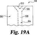
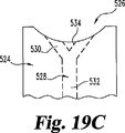
その他の形態において、本発明は、試験片を作製する方法を配設する。ベース基板、スペーシング層およびカバー層が配設される。空間が、スペーシング層中で形成され、前記空間が、細長い部位と球状部位を持つ。スペーシング層が、ベース基板に対して積層され、カバー層が、スペーシング層に対して積層され、それによって、試験片プリカーサー部(precursor)が形成される。試験片を作製するために、プリカーサー部を通して切断が行われ、その切断が、空間の球状部位を横切り、試験片の試料受入縁部を形成し、そこで、空間が、試験片の試料受入縁部における試験受入開口部中にて終結している、フレア状に形成された部位を持つ試料受入チャンバーを定義している。 In another aspect, the present invention is to arrange the method for producing a test piece. A base substrate, a spacing layer and a cover layer are disposed . A space is formed in the spacing layer, and the space has an elongated portion and a spherical portion. A spacing layer is laminated to the base substrate, and a cover layer is laminated to the spacing layer, thereby forming a specimen precursor portion . To prepare a test piece, cut is made through the precursor portion, the cutting cross the spherical portion of the space, to form a sample receiving edges of the test piece, where, space, sample receiving edges of the test piece Defines a sample receiving chamber having a flared portion that terminates in the test receiving opening in FIG.
本発明の方法の好ましい形態において、試料受入縁部が、試験片の末端を含み、試料受入開口部が外側にフレア状に形成し、試験片の投与される側の端部がテーパーしている。 In a preferred form of the method of the present invention, the sample receiving edge includes the end of the test piece , the sample receiving opening is flared outwardly, and the end of the test piece on the administration side is tapered. .
本発明は、非常に簡単に投与される試験片を配設し、強固であるが、しかし順応性がある製造工程を配設する。本発明を特徴づける種々の他の特徴が、付随する請求項において、詳細に言及されている。 The present invention, arranged a test piece to be administered very easily, but it is robust, but to arrange the manufacturing process is flexible. Various other features that characterize the invention are pointed out with particularity in the appended claims.
本発明、その利点およびそれより得られる目的のよりよい理解のために、本発明の例示され、記述された好ましい実施形態が存在する、図面および付随する記述に対して、参照されるべきである。 For a better understanding of the present invention, its advantages, and the objects obtained therefrom, reference should be made to the drawings and accompanying description, in which there are illustrated and described preferred embodiments of the invention. .
ここで図面を参照して、いくつかの図を通して、同様の参照番号および文字が、相当する構造を示唆する。 Referring now to the drawings wherein like reference numerals and characters indicate corresponding structures throughout the several views.
本発明の原理の理解を促進する目的のために、本明細書で例示した特定の実施形態に対して参照し、特定の言語を、同様に記述するために使用する。それによって本発明の目的の制限が意図されていないことが理解される。記述した工程または器具における、任意の変化およびさらなる改変、および本明細書で記述されたような本発明の原理のさらなる任意の適用が、本発明が関する技術分野の当業者に通常おこるように、意図される。 For the purpose of promoting an understanding of the principles of the invention, reference will be made to specific embodiments illustrated herein, and specific languages will be used to describe the same. It is understood that no limitation of the purpose of the invention is thereby intended. As any changes and further modifications in the described steps or apparatus and further optional applications of the principles of the invention as described herein will generally occur to those skilled in the art to which the invention pertains, Intended.
システム
本発明は、試料流体中の検体を査定するために有用なシステムに関する。システムには、標的検体に対して、試料流体を評価するための器具および方法が含まれる。より完全に本明細書以下で記述されるように、評価は、検体の存在を検出することから、検体の濃度を決定することまでの範囲である。検体および試料流体は、試験システムが適切である任意のものでありうる。例示のみの目的のために、好ましい実施形態を、検体がグルコースで、試料流体が血液または間質液であるように記述する。しかしながら、本発明は、明確にその目的を制限されない。
System The present invention relates to a system useful for assessing an analyte in a sample fluid. The system includes instruments and methods for evaluating sample fluid against a target analyte. As described more fully herein below, the assessment ranges from detecting the presence of the analyte to determining the concentration of the analyte. The analyte and sample fluid can be any suitable test system. For illustrative purposes only, the preferred embodiment is described such that the analyte is glucose and the sample fluid is blood or interstitial fluid. However, the present invention is not clearly limited in its purpose.
センサー
システムの1つのコンポーネントは、試料流体のための試料受入チャンバーと、試験検体の存在下で、電気化学シグナルを産出するために好適な試薬を含む、電気化学的センサーである。センサーは、好ましくは、使い捨て試験片、とりわけ、試料受入チャンバーと連結する縁部開口部を配設する、薄版状構造を持つものを含む。試薬が、チャンバー内に位置する作用電極へ、電気化学的信号を送信するための位置に、試料受入チャンバー内で配置される。グルコース検出のためのような、適切な環境において、試薬が、酵素および任意にメディエーターを含みうる。
One component of the sensor system is an electrochemical sensor that includes a sample receiving chamber for the sample fluid and a reagent suitable for producing an electrochemical signal in the presence of the test analyte. Sensors are preferably disposable test strips, among other things, to arrange the edge opening which connects the sample receiving chamber, including those having a thin plate-like structure. A reagent is placed in the sample receiving chamber at a location for transmitting an electrochemical signal to a working electrode located in the chamber. In a suitable environment, such as for glucose detection, the reagent can include an enzyme and optionally a mediator.
メーター
センサーは、試料液体中の検体の決定のために、メーターと組み合わせて使用される。メーターは通常、センサーの電極との連結を含み、検体の濃度に相当する電気化学的シグナルを評価するための回路を含む。メーターはまた、試料流体が、センサーによって受入されたこと、および試料の量が試験のために十分であること、を決定するための手段を含みうる。メーターは典型的に、解析の結果を保存し、表示し、または別の器具へ、データを配設してよい。
A meter sensor is used in combination with a meter to determine the analyte in the sample liquid. The meter typically includes a circuit for evaluating an electrochemical signal corresponding to the analyte concentration, including coupling to the sensor electrodes. The meter may also include means for determining that sample fluid has been received by the sensor and that the amount of sample is sufficient for testing. Meter as Typically, stores the results of the analysis, the display or another instrument, it may be arranged data.
検体−特性
システムは、検体に対する、定量的または定性的表示いずれかを配設可能である。1つの実施形態において、システムは、単に、試料流体中の検体の存在を示唆する。システムはまた、試料流体中の検体の量または濃度の読みとりを配設しうる。好ましい実施形態において、検体濃度の非常に正確で、精密な読み取りが、少量の試料流体から迅速に得られることが、本発明の特徴である。
Sample - characteristic system to the analyte can be disposed either quantitative or qualitative display. In one embodiment, the system simply suggests the presence of an analyte in the sample fluid. The system may also arrange for a reading of the amount or concentration of the analyte in the sample fluid. In a preferred embodiment, it is a feature of the present invention that a very accurate and precise reading of the analyte concentration can be quickly obtained from a small amount of sample fluid.
検体−型
システムは、広い範囲の検体の定量のために有用である。たとえば、試験片は、検体の存在を査定するために使用可能である、任意の好適な化学反応との使用に、簡単に適合する。もっとも好ましくは、システムは、生物学的流体中の検体の試験のために配置され、使用される。そのような検体には、たとえば、グルコース、コレステロール、HDLコレステロール、トリグリセリド、乳酸、乳酸デヒドロゲナーゼ、アルコール、尿酸および3−ヒドロキシブチル酸(ケトン体)が含まれうる。システムに対する相応の改変が、当業者に対して理解されうる。説明の目的のために、そしてとりわけ好ましい実施形態において、システムが、生物学的流体中のグルコースの検出に関して、記述される。
Specimen-type systems are useful for the quantification of a wide range of analytes. For example, the test strip is easily adapted for use with any suitable chemical reaction that can be used to assess the presence of an analyte. Most preferably, the system is arranged and used for testing of an analyte in a biological fluid. Such specimens can include, for example, glucose, cholesterol, HDL cholesterol, triglycerides, lactic acid, lactate dehydrogenase, alcohol, uric acid and 3-hydroxybutyric acid (ketones). Appropriate modifications to the system can be understood by those skilled in the art. For illustrative purposes and in a particularly preferred embodiment, the system is described with respect to the detection of glucose in a biological fluid.
干渉物
試験法は、試料流体中の干渉物の存在によって、様々に影響を受けうる。たとえば、血液試料中のグルコースに関する試験は、酸素、ビリルビン、ヘマトクリット、尿酸、アスコルビン酸塩、アセトアミノフェン、ガラクトース、マルトースおよび脂質のような因子によって影響を受けうる。本システムは、試料流体にまた存在しうる干渉物の悪影響を最小化または削除するために適合可能である。これらの影響は、影響が少ないことが公知な化学物質の選択、または可能な干渉物などによって、試験物質およびパラメータの適切な選択によって、解決されうる。本技術分野で公知なように、干渉物が試験ゾーンへ侵入することから防止する、コーティングまたはフィルムの使用のような、他の段階を実施して、可能性のある干渉物効果を解決しうる。さらに、電極配置または問い合わせ方法に対する改変を、干渉物の効果を最小化するために使用可能である。
Interferer test methods can be affected in various ways by the presence of interferents in the sample fluid. For example, testing for glucose in a blood sample can be affected by factors such as oxygen, bilirubin, hematocrit, uric acid, ascorbate, acetaminophen, galactose, maltose and lipids. The system is adaptable to minimize or eliminate the adverse effects of interferents that may also be present in the sample fluid. These effects can be resolved by the appropriate selection of test substances and parameters, such as by selection of chemicals known to have low effects, or possible interferences. As known in the art, other steps, such as the use of coatings or films, to prevent interferences from entering the test zone can be implemented to resolve potential interference effects. . Furthermore, modifications to the electrode placement or interrogation method can be used to minimize the effects of interferers.
流体の種類
本システムは、広い範囲の種々の試料流体で有用であり、好ましくは、生物学的流体中の検体の検出のために使用される。この文脈において、語句「生物学的流体(biological fluid)」には、検体が測定可能である任意の体液、たとえば間質液、皮膚液、汗、涙、尿、羊膜液、髄液および血液が含まれる。本発明の文脈において、語句「血液(blood)」には、全血およびその細胞を含まない成分、すなわち、血漿および血清が含まれる。さらに、本システムは、試験のためのシステムの完全性を確認するために、従来の方法にて使用される、対照流体と連結して有用である。
Fluid Types The system is useful with a wide range of different sample fluids and is preferably used for the detection of analytes in biological fluids. In this context, the phrase “biological fluid” includes any body fluid that an analyte can measure, such as interstitial fluid, skin fluid, sweat, tears, urine, amniotic fluid, cerebrospinal fluid, and blood. included. In the context of the present invention, the phrase “blood” includes whole blood and its cell-free components, ie plasma and serum. In addition, the system is useful in conjunction with a control fluid used in conventional methods to confirm the integrity of the system for testing.
好ましい実施形態において、本システムは、グルコースの試験のために使用される。本例の試料流体は、とりわけ、たとえば、指先または許可された他の部位(たとえば、前腕、掌、耳たぶ、上腕、カーフおよび大腿部)より得られた、新鮮なキャピラリー血液、新鮮な静脈血、およびシステムとともに、またはシステムのために供給された対照溶液が含まれうる。 In a preferred embodiment, the system is used for glucose testing. The sample fluid of this example is, for example, fresh capillary blood, fresh venous blood obtained from, for example, a fingertip or other authorized site (eg, forearm, palm, earlobe, upper arm, calf and thigh) And a control solution supplied with or for the system.
流体は、任意の様式で取得され、試験片に伝達しうる。たとえば、血液試料を、ランセットなどで、皮膚を切開し、ついで、試験片を、皮膚表面に現れた流体と接触させることによって、従来の様式にて得ることが可能である。試験片が、非常に小さな流体試料で有用であることが、本発明の一つの観点である。したがって、皮膚をわずかに切開することのみが、試験に必要な流体の容量を産出するために必要であること、およびそのような方法に関する痛みや他の問題を、最小化するか、排除することが可能であることが、本発明の望ましい特徴である。 The fluid can be obtained and transmitted to the specimen in any manner. For example, a blood sample can be obtained in a conventional manner by incising the skin, such as with a lancet, and then contacting the test strip with fluid appearing on the skin surface. It is an aspect of the present invention that the test strip is useful with very small fluid samples. Therefore, only a slight incision in the skin is necessary to produce the volume of fluid needed for the test, and the pain and other problems associated with such methods should be minimized or eliminated. This is a desirable feature of the present invention.
皮膚上の異なる局所が、ランセットで切開する場合に、より多くの、またはより少ない血液量を産出しうることがまた公知である。たとえば、ランセットで切開する場合に、比較的多量の血液を産出するので、指先が、血液試料を得るための、一般的に使用される部位である。しかしながら、より多量の血液を産出する領域は、一般的に、利用者にとってより大きな程度の痛みを伴うことも知られている。したがって、本システムのさらなる利点は、試料流体の容量が充分に少なく、さらに試験片が、典型的に、掌および上腕のようなあまり生産的ではないが痛みが少ない皮膚の領域を、ランセット切開して得られた、血液量で有用である。試験のための試料流体を得るために、これらの部位を使用することは、しばしば「代替部位試験(alternate site testing)」と呼ばれる。本発明は、とりわけ、これらの代替部位で得られた、試料流体、たとえば、血液または間質液との使用によく適合する。 It is also known that different regions on the skin can produce more or less blood volume when incised with a lancet. For example, since a relatively large amount of blood is produced when an incision is made with a lancet, the fingertip is a commonly used site for obtaining a blood sample. However, it is also known that areas that produce larger amounts of blood are generally associated with a greater degree of pain for the user. Thus, a further advantage of the present system is that the sample fluid volume is sufficiently low, and that the specimen typically lancets open areas of the skin that are less productive but less painful, such as the palm and upper arm. It is useful in the blood volume obtained. Using these sites to obtain sample fluids for testing is often referred to as “alternate site testing”. The present invention is particularly well suited for use with sample fluids such as blood or interstitial fluid obtained at these alternative sites.
試験片一般
イントロダクション
試験片は、いくつかの基礎的成分を含む。ストリップは、試料流体が試験のために受入されるチャンバーを定義している小体を含む。この「試料受入チャンバー(sample-receiving chamber)」が、好適な手段、好ましくは、キャピラリー活性によって、また任意に圧力または吸引によって補助されて、試料流体で満たされる。試料受入チャンバーには、電極および、試料流体中の検体を示す電気化学シグナルを産出するために好適な化学物質が含まれる。
Specimen General Introduction
The specimen contains several basic components. The strip includes a body defining a chamber in which sample fluid is received for testing. This “sample-receiving chamber” is filled with the sample fluid by suitable means, preferably assisted by capillary activity and optionally by pressure or suction. The sample receiving chamber includes an electrode and a chemical suitable for producing an electrochemical signal indicative of the analyte in the sample fluid.
基本的概要
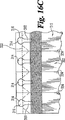
とりわけ、図面を参照して、本発明にしたがって有用である試験片の好ましい実施形態が示されている。試験片10には、ベース基板12、スペーシング層14、および本体カバー18とチャンバーカバー20を含むカバー層16が含まれる。スペーシング層14には、ベースとなる基板(以下、ベース基板という)12およびカバー層16間に伸びている、試料受入チャンバー24を配設するために空間部位22が含まれる。
Basic Overview Referring to the drawings in particular, preferred embodiments of test strips useful in accordance with the present invention are shown. The
ベース基板12が、複数の電極28と、コンタクトパッド32中で終結している電極トレース30を含む、電極システム26を持つ。電極は、試料受入チャンバー24内に配置されている、電極トレース30のそれらの部分として定義される。電極システム26の種々の配置が、本明細書以下で列記されるように、使用されうる。好適な試薬システム33が、試料受入チャンバー内の、少なくとも一部分の電極または電極対28を被覆する。
The
スペーシング層16を被覆している本体カバー18およびチャンバーカバー20が、そのあいだのスロット34を定義し、そのスロットが、試料が、縁部開口部または流体受入開口部35から、チャンバーへ入った時に、空気がチャンバーから逃げられるように、試料受入チャンバーと連結している通気開口部を定義している。したがって、試験片には、投与される側の端部36およびメーター挿入末端38が含まれる。投与される側の端部の形態は、典型的には、利用者を補助するために、メーター末端から区別可能である。図1で示したように、好ましくは、投与される側の端部36は流体試料と、試験片10の試料受入チャンバー24を整列させる場合に、利用者を補助するために、台形形態を形成させるために、テーパーしている、または細くなる。投与される側の端部36のテーパー形態によって、利用者の皮膚への、投与される側の端部の可能な接触表面が最小化され、それによって、以下でより詳細に記述するように、試料受入チャンバー24の、流体試料との整列を補助する。
The
さらに、投与される側の端部でのストリップグラフィックおよび対照色が、好ましくは、ストリップ設計の直感性をさらに改善するために使用される。同様に、メーター挿入末端にて、山形紋31が、メーター内へのストリップの挿入の方向を示唆している。さらに、山形紋31は、試験片10の大きさに合わされ試験片上に配置されているため、山形紋31はメーターの内部であり、したがって、試験片10が適切にメーター内に挿入された場合に、視界から隠れる。(矢印と反対の)山形紋31の大きさおよび位置は、利用者が、山形紋31でマークされた試験片を、メーター内に無理に押し込み、試験片10に障害を与えるか、または破壊する可能性を減少させる。
In addition, strip graphics and contrast colors at the administered end are preferably used to further improve the intuitiveness of the strip design. Similarly, at the meter insertion end, a
一般的寸法
試験片は、保存および利用のコンパクトさ、および簡便さのために大きさを設定される、比較的小さな器具である。典型的な実施形態において、ストリップ長さは、長さにして、20〜50mm程度、好ましくは約33〜約38mmであり、幅にして、5〜15mm程度、好ましくは約7〜約9mmある。スロットまたは通気開口部34から、メーターの縁部までの距離は、血圧が存在しない「グラブエリア(grab area)」を配設するように、そして、メーター接触領域の血液汚染に対して防御するために、大きさが決められ、したがって、5〜35mm、好ましくは13mm以上の範囲でありうる。メーターに挿入される、(メーター挿入末端38からの)試験片部位の長さは、好ましくは、試験片の長軸にそって、6.0mm以下である。
General dimensions
A specimen is a relatively small instrument that is sized for compactness and convenience of storage and use. In a typical embodiment, the strip length is about 20-50 mm in length, preferably about 33 to about 38 mm, and about 5-15 mm in width, preferably about 7 to about 9 mm. From the slot or vent
試験片の好ましい薄版構造はまた、比較的薄い器具を配設する。ストリップの最小の厚さによって、利用者に便利な適切な容器内のストリップの準備されたパッケージングが可能になる。たとえば、試験片の全厚は、約500〜525μmでありうる。メーター接触内へ挿入される試験片部位の厚さは、約250μmでありうる。 Preferred thin plate structure of the specimen also provided a relatively thin instrument. The minimum thickness of the strip allows for ready packaging of the strip in a suitable container convenient for the user. For example, the total thickness of the specimen can be about 500-525 μm. The thickness of the specimen site inserted into the meter contact can be about 250 μm.
基板
試験片は、電極システムおよび他のコンポーネントを支持する絶縁物質を含む、ベース基板12を含む。典型的には、ビニルポリマー類、ポリイミド類、ポリエステル類およびスチレン類のようなプラスチックが、必要な電気的および構造的特性を配設する。さらに、試験片が、好ましくは、物質のロールからマス産出可能であることから、物質特性が、ロール処理に対して十分な柔軟性を持つことが望ましく、また、完成したストリップに対して有用な堅さを与えることが望ましい。ベース基板は、ポリエステル、とりわけ高温ポリエステル物質、ポリエチレンナフタラート(PEN)、およびポリイミド、またはこれらの2つまたはそれ以上の混合物などの、可塑性重合性物質として選択可能である。ポリイミド類は、たとえば、デラウエア州、ウィルミントンのデュポン社(E.I.duPont de Nemours and Company)より、Kapton(登録商標)の商品名で市販されている。とりわけ好ましいベース基板の材料は、デュポン社から入手可能なMELINEX(登録商標)329である。
substrate
The test specimen includes a
電極
型
本発明は、センサー内での電気化学的酸化および還元反応によって、検体の存在を検出するため、および/または検体の濃度を測定するために、配置された器具である、「電気化学的センサー(electrochemical sensor)」に関する。これらの反応は、検体の量または濃度に相関する電気信号に変換される。したがって、試験片は、一組の測定電極、たとえば、少なくとも1つの作用電極と一つの対極を含む、電極システム26を、試料受入チャンバー内に含む。試料受入チャンバーは、チャンバー内に入る試料流体が、作用電極および対極両方と、電解接触にて配置されるように、配列される。このことによって、電流が、測定電極間を流れて、検体の電気酸化または電気還元に影響を与える。
Electrode Type The present invention is an instrument that is placed to detect the presence of an analyte and / or to measure the concentration of an analyte by electrochemical oxidation and reduction reactions in a sensor. Relates to "electrochemical sensor". These reactions are converted into electrical signals that correlate with the amount or concentration of the analyte. Thus, the test strip includes an
本発明の文脈にて、「作用電極(working electrode)」は、酸化還元メディエーターの仲介ありまたはなしで、検体が電気酸化または電気還元される、電極である。語句「対極(counter electrode)」は、本明細書にて、作用電極と対となり、作用電極を通過する電流と程度が等しく、符号が反対である電気化学的電流が流れる、電極を意味する。語句「対極」は、参照電極としても機能する対極(すなわち、カウンター/参照電極)も含むことを意味する。 In the context of the present invention, a “working electrode” is an electrode where an analyte is electrooxidized or electroreduced with or without the mediation of a redox mediator. The phrase “counter electrode” means herein an electrode that is paired with a working electrode and through which an electrochemical current of the same magnitude and opposite sign flows through the working electrode. The phrase “counter electrode” is meant to include a counter electrode that also functions as a reference electrode (ie, a counter / reference electrode).
作用および対極、および電極システムの残りの部分は、本技術分野で公知の、種々の物質から形成されうる。電極は、比較的低い電気的抵抗を持つべきであり、試験片の操作範囲にわたり、電気化学的に不活性であるべきである。作用電極の好適なコンダクターには、金、パラジウム、白金、炭素、チタン、二酸化ルテニウム、および酸化インジウムスズ、およびイリジウム、ならびに他のものが含まれる。対極は、同一または異なる物質、たとえば銀/塩化銀からなってよい。好ましい実施形態において、ワーキングおよび対極は両方とも金電極である。 The working and counter electrode, and the remainder of the electrode system, can be formed from a variety of materials known in the art. The electrode should have a relatively low electrical resistance and should be electrochemically inert over the operating range of the specimen . Suitable conductors for the working electrode include gold, palladium, platinum, carbon, titanium, ruthenium dioxide, and indium tin oxide, iridium, and others. The counter electrode may consist of the same or different materials, for example silver / silver chloride. In a preferred embodiment, the working and counter electrodes are both gold electrodes.
電極適用
電極は、適切な伝導性および完全性の電極を産出する任意の様式で、ベース基板に適用しうる。例示的工程は、本技術分野でよく知られており、たとえば、スパッタリング、印刷などが含まれる。好ましい実施形態において、金電極が、ベース基板をコートし、ついで、コーティングの選択された部位を取り除いて、電極システムを産出することによって配設される。好ましい除去方法は、レーザー切断であり、より好ましくは、広領域レーザー切断である。
Electrode application The electrode may be applied to the base substrate in any manner that yields an electrode of suitable conductivity and integrity. Exemplary processes are well known in the art and include, for example, sputtering, printing, and the like. In a preferred embodiment, a gold electrode is disposed by coating the base substrate and then removing selected portions of the coating to yield an electrode system. A preferred removal method is laser cutting, more preferably wide area laser cutting.
レーザー切断技術には典型的に、単一金属層、または絶縁物質と伝送性物質を含む多重層組成物、たとえば、絶縁物質上にコートされたか、または絶縁物質に積層された金属層の金属性−ラミネート(以下で議論する)を切断することが含まれる。金属性層には、純粋な金属、合金、酸化物または金属性コンダクターである、他の物質が含まれる。金属または金属様コンダクターの例には、アルミニウム、(グラファイトなどの)炭素、コバルト、銅、ガリウム、金、インジウム、イリジウム、鉄、鉛、マグネシウム、水銀(アマルガムとして)、ニッケル、ニオビウム、オスミウム、パラジウム、白金、レニウム、ロージウム、セレニウム、シリコーン(高度にドープされた多晶質性シリコンなど)、銀、タンタル、スズ、チタニウム、タングステン、ウラニウム、バナジウム、亜鉛、ジルコニウム、これらの混合物、これらの金属の合金または固体溶液が含まれる。好ましくは、物質は、生物学的システムに対して、本質的に不応答性であるように選択され、このような物質には、金、白金、パラジウム、イリジウム、銀またはこれらの物質の合金または酸化インジウムスズが含まれる。金属性層は、任意の所望の厚さであり得る。好ましい実施形態において、厚さは約50nmである。 Laser cutting techniques typically include a single metal layer or a multi-layer composition comprising an insulating material and a transmissible material, for example, a metallic layer coated on or laminated to an insulating material. -Cutting the laminate (discussed below). The metallic layer includes other materials that are pure metals, alloys, oxides or metallic conductors. Examples of metal or metal-like conductors include aluminum, carbon (such as graphite), cobalt, copper, gallium, gold, indium, iridium, iron, lead, magnesium, mercury (as amalgam), nickel, niobium, osmium, palladium , Platinum, rhenium, rhodium, selenium, silicone (such as highly doped polycrystalline silicon), silver, tantalum, tin, titanium, tungsten, uranium, vanadium, zinc, zirconium, mixtures of these, Alloys or solid solutions are included. Preferably, the material is selected to be essentially unresponsive to biological systems, such as gold, platinum, palladium, iridium, silver or alloys of these materials or Indium tin oxide is included. The metallic layer can be of any desired thickness. In a preferred embodiment, the thickness is about 50 nm.
配置
電極システムは、試験片およびメーターの操作に適合する種々の配置を持ちうる。任意の実施形態に関して、作用および対極は好ましくは、これらを覆うのに必要な試料流体の量を最小化させるために、配置され、必要な大きさにする。また、電極は、比較的安価な携帯型メーターを用いて測定可能であるように、十分な程度の電流束を維持するために配置されることが好ましい。
Arrangements The electrode system can have a variety of arrangements that are compatible with test strip and meter operation. For any embodiment, the working and counter electrodes are preferably arranged and sized as necessary to minimize the amount of sample fluid needed to cover them. In addition, the electrodes are preferably arranged to maintain a sufficient current flux so that they can be measured using a relatively inexpensive portable meter.
さらなる例の方法によって、好ましい実施形態には、作用電極の両側の周りに伸びる、対極が含まれる。したがって、対極は2つの要素を持ち、試料流体が、試料受入チャンバーに入る時に、一つは作用電極の前であり、他は作用電極の後ろにある。よりとりわけ、対極には、試料受入チャンバーを越えて伸びている、要素40および42が含まれる。これらの要素のそれぞれが、約250μmの幅である。作用電極要素44は、約250μmの幅を持ち、2つの対極要素のそれぞれから約255μm離れている。これは、測定電極に関する多数の配置のただ1つであることが理解されるであろう。
By a further example method, a preferred embodiment includes a counter electrode that extends around both sides of the working electrode. Thus, the counter electrode has two elements, one when the sample fluid enters the sample receiving chamber, one before the working electrode and the other behind the working electrode. More particularly, the counter electrode includes
トレース30およびコンタクトパッド32は、試験片に関する意図する機能と一致する多数の様式で配設されうる。電極システムのこれらのコンポーネントは、好ましくは、電極と同一の物質からなり、同様の様式で、電極の適用と同時に、ベース基板に好ましく適用される。好ましい実施形態において、とりわけ、参考文献によって本明細書にて組み込まれている開示物である、表題「バイオセンサーを作製する方法(Method of Making a Biosensor)」の、2003年6月20日に出願された、米国特許出願第10/601,144号にて記述されたような、トレースおよびコンタクトパッドは金であり、レーザー切断によって形成される。しかしながら、他の物質および適用方法を利用して良い。
化学物質
試薬組成物
試験片には、試料受入チャンバー内に、試料流体中の検体の存在を表す、電気化学的シグナルを産出するために、試験検体と反応するための、化学試薬が含まれる。試薬層には、種々の検体の存在、および/または濃度を決定するために選択された種々の活性コンポーネントを含みうる。試験化学物質はしたがって、査定されるべき検体に関して選択される。本技術分野で良く公知のように、種々の検体それぞれとの使用のために利用可能な多数の化学物質が存在する。たとえば、1つの好ましい実施形態において、本発明の試験片は、血中のグルコースの存在を決定するために選択可能である、1つまたはそれ以上の酵素、補酵素、および補因子を含みうる。したがって、適切な化学物質の選択は、当業者によく知られており、本明細書でのさらなる記述は、種々の検体と、試験片を作製し、使用することを可能にするために必要ではない。
Chemical reagent composition
The test strip includes a chemical reagent in the sample receiving chamber for reacting with the test analyte to produce an electrochemical signal indicative of the presence of the analyte in the sample fluid. The reagent layer can include various active components selected to determine the presence and / or concentration of various analytes. The test chemical is therefore selected for the analyte to be assessed. As is well known in the art, there are a number of chemicals available for use with each of the various analytes. For example, in one preferred embodiment, the test strips of the present invention can include one or more enzymes, coenzymes, and cofactors that can be selected to determine the presence of glucose in the blood. Thus, the selection of appropriate chemicals is well known to those skilled in the art, and further description herein is not necessary to allow various specimens and test strips to be made and used. Absent.
アジュバント
従来の様式において、試薬化学物質は、試薬特性または特徴を増強するための、種々のアジュバントを含んで良い。たとえば、化学物質は、試薬ストリップ上への試薬組成物の配置を促進するため、およびストリップへのその接着を改善するため、または試料流体による、試薬組成物の加水分解の速度を増大させるための、物質を含んで良い。さらに、試薬層は、得られる乾燥試薬層の物理的特徴、および解析のための液体試験試料の取り込みを増強するために選択した成分を含んで良い。試薬組成物と使用するためのアジュバント物質の例には、濃縮物、粘土調節物、フィルム形成物、安定化剤、緩衝液、洗浄剤、ゲル化剤、充填剤、フィルムオープナー、着色剤、および揺変性付与試薬が含まれる。
Adjuvants In a conventional manner, the reagent chemical may include various adjuvants to enhance reagent properties or characteristics. For example, the chemical may facilitate the placement of the reagent composition on the reagent strip and improve its adhesion to the strip or to increase the rate of hydrolysis of the reagent composition by the sample fluid. May contain substances. In addition, the reagent layer may contain the physical characteristics of the resulting dry reagent layer and components selected to enhance the uptake of liquid test samples for analysis. Examples of adjuvant materials for use with reagent compositions include concentrates, clay modifiers, film formers, stabilizers, buffers, detergents, gelling agents, fillers, film openers, colorants, and A thixotropic agent is included.
試験試料の好ましい実施形態において、主なチャンバーは使用の前に空である。本発明にしたがった試験片の非常に小さな試料チャンバーにおいて、試薬層が薄く、均一であることが好ましい。試料受入チャンバーが非常に小さく、約1μl以下であるので、チャンバーの深さ、または垂直高さが小さい。したがって、試薬層は、チャンバーの内部キャビティのほとんどを占拠すべきでない。試薬層は、チャンバー内の試験試料のために、豊富な空間を残すために十分薄いべきである。さらに、液体試験試料が、薄い試薬層をより迅速に加水分解または溶解する。上の反応スキーム中で議論されるように、メディエーターおよびメディエーター酸化還元産物が、電極へ、試薬層/勾配を通して、およびその中で拡散する。反応性コンポーネントおよび中間体は、薄い試薬を通して拡散するために短い距離を持ち、したがって、電極への拡散が、少ない時間で生じる。さらに、電極での、メディエーター酸化還元産物の捕獲効率は、厚い層よりも、酵素の薄い層に関して大きい。 In a preferred embodiment of the test sample, the main chamber is empty before use. In a very small sample chamber of a test strip according to the present invention, the reagent layer is preferably thin and uniform. Since the sample receiving chamber is very small, about 1 μl or less, the chamber depth or vertical height is small. Thus, the reagent layer should not occupy most of the internal cavity of the chamber. The reagent layer should be thin enough to leave abundant space for the test sample in the chamber. In addition, the liquid test sample hydrolyzes or dissolves the thin reagent layer more quickly. As discussed in the reaction scheme above, mediators and mediator redox products diffuse to, through and within the reagent layer / gradient. Reactive components and intermediates have a short distance to diffuse through thin reagents, and thus diffusion to the electrode occurs in less time. Furthermore, the capture efficiency of the mediator redox product at the electrode is greater for a thin layer of enzyme than for a thick layer.
逆に、厚い試薬層は、液体試験試料を加水分解する、または溶解するために、より時間がかかり、厚い試薬層は、メディエーター/メディエーター酸化還元産物にとって、電極へ接近するためにかかる時間を増加させる。これは、検体濃度を決定するための時間を遅らせ、決定に間違いを生じ得る。 Conversely, a thick reagent layer takes more time to hydrolyze or dissolve the liquid test sample, and a thick reagent layer increases the time it takes for the mediator / mediator redox product to approach the electrode. Let This delays the time to determine the analyte concentration and can make mistakes in the determination.
試薬層は、均一な厚さをもつことが望ましい。厚さが不均質であることは、検体濃度を決定することにおいて変動を導きうる。好ましい実施形態において、試薬層は、全試料受入チャンバーを通して、均質な厚さを持つ。この好ましい実施形態において、試薬層は、チャンバーを定義している垂直側壁に隣接した試料受入チャンバーの周辺で、チャンバーの中心部位よりも厚くはない。したがって、試薬層は、メニスカス輪郭形状を示さない。 It is desirable that the reagent layer has a uniform thickness. Non-uniform thickness can lead to variations in determining analyte concentration. In a preferred embodiment, the reagent layer has a uniform thickness throughout the entire sample receiving chamber. In this preferred embodiment, the reagent layer is not thicker at the periphery of the sample receiving chamber adjacent to the vertical sidewall defining the chamber than the central portion of the chamber. Therefore, the reagent layer does not exhibit a meniscus contour shape.
試薬組成物は、基体層上で、薄く、均一な層内に沈着可能な、粘性溶液として処方される。試薬組成物には、試薬層の物理的特性を増強するために、濃縮物および揺変性物が含まれる。濃縮物は、そこに均質に分散している残りのコンポーネントを持つ濃い、液体マトリックスを配設するために選択される。濃縮物および揺変性物はまた、沈着した後、および乾燥前に、液体または半ペースト物質が、基体層の表面上に流れることまたは広がることから阻止する。試薬組成物が沈着した後、簡単に加水分解可能なマトリックスまで、迅速に乾燥する。 The reagent composition is formulated as a viscous solution that can be deposited in a thin, uniform layer on the substrate layer. The reagent composition includes concentrates and thixotropic agents to enhance the physical properties of the reagent layer. Concentrate, dark with remaining components homogeneously dispersed therein, it is selected in order to dispose the liquid matrix. Concentrates and thixotropics also prevent liquid or semi-paste materials from flowing or spreading on the surface of the substrate layer after deposition and prior to drying. After the reagent composition is deposited, it is quickly dried to a matrix that can be easily hydrolyzed.
試薬組成物が、風乾または熱乾燥いずれかで、迅速に乾燥するために配設される。乾燥後、沈着した試薬層が、約1ミクロン〜約20ミクロンのあいだの厚さを表す。よりとりわけ、乾燥試薬層が、約2ミクロン〜約6ミクロンのあいだの厚さを示す。 The reagent composition is arranged for rapid drying, either air dried or heat dried. After drying, the deposited reagent layer exhibits a thickness between about 1 micron and about 20 microns. More particularly, the dry reagent layer exhibits a thickness between about 2 microns and about 6 microns.
試薬組成物は、スロット染色コーティング、カーテンコーティング、熱融解コーティング、ロータリースクリーンコーティング、ドクターブレードまたは空気ナイフコーティング、マイヤーバーコーティングおよび逆ロールコーティング技術を含む、種々のコーティング方法を用いて、試験片表面上に沈着可能である。これらの技術は、当業者に公知である。好ましくは、試薬層は、約40μm〜約100μmのあいだの厚さで、ウェット組成物として、柔軟性のウェブ上に沈着する。より好ましくは、試薬組成物は、約60μm〜約80μmのあいだの厚さで、ウェット組成物として沈着する。組成物は、測定電極の最上に直接、そして、連続した細いバンドとして、多重試験片のウェブの長さにそって、試薬の均質薄層として適用して良い。好ましい実施形態において、細いバンドは、約7mm〜8mmのあいだの幅と、約3um〜約20umのあいだの乾燥厚さを持つ。組成物はまた、そのような外側電極の所望の機能性に依存して、試料受入チャンバー内に存在しうる他の電極上に適用され得る。 The reagent composition can be applied to the specimen surface using a variety of coating methods, including slot dye coating, curtain coating, thermal melt coating, rotary screen coating, doctor blade or air knife coating, Mayer bar coating and reverse roll coating techniques. Can be deposited. These techniques are known to those skilled in the art. Preferably, the reagent layer is deposited on the flexible web as a wet composition with a thickness between about 40 μm and about 100 μm. More preferably, the reagent composition is deposited as a wet composition with a thickness between about 60 μm and about 80 μm. The composition may be applied directly on top of the measuring electrode and as a continuous thin band as a homogeneous thin layer of reagent along the length of the web of multiple specimens . In a preferred embodiment, the thin band has a width between about 7 mm and 8 mm and a dry thickness between about 3 um and about 20 um. The composition may also be applied on other electrodes that may be present in the sample receiving chamber, depending on the desired functionality of such outer electrodes.
スペーシング層
配置
試験片は、ベース基板体を被覆し、部分的に、試料受入チャンバーを画定する、スペーシング層14を含む。とりわけ、スペーシング層14は、実質的に、試料受入チャンバー24の高さと境界線を画定している、空間部位22を含む。空間部位22は、縁部開口部を持つように都合良く配置し、それによって試料流体が、縁部開口部と接触して、試料受入チャンバー内へ入る。縁部開口部は、好ましくは、側縁部上の配置も有用であるが、試験片の末端に局在する。
Spacing layer placement
The specimen includes a
物質
スペーシング層14は、試験片との作製のために有用な任意の物質からなって良い。スペーシング層は部分的に、試料受入チャンバーの高さを画定するので、物質は、所望のチャンバーの高さに適切な厚さで、十分な強さを持つべきである。スペーシング層の他の機能は、ベース基板12の上表面に沿って伸びる電極トレースを保護することである。物質はまた、熱感受性または圧力感受性接着剤、または熱またはレーザー溶接のような、他の手段のいずれかによって、ベース基板およびカバー物質に簡単に接着すべきである。好適な物質の例には、100μm PET、またはアドヘジブズ リサーチ インコーポレイテッド(Adhesives Research Inc.)から入手できるARCare 90132のような接着剤質でコートされたか、または混合したPET箔が含まれる。
カバー層
配置
カバー層16は、スペーシング層14上で受けられ、接着する。カバー層の1つの機能は、試料受入チャンバーの最上表面を形成することである。他の機能は、試験試料の獲得を助けるための、親水性表面の配設である。さらに、カバー層16は、好ましくは、試料流体が、試料受入チャンバー内に入り、移動する時に、チャンバーの中より空気が逃げることが出来るように、通気開口部34を画定する。
Cover Layer
カバー層は、図1Bで示したように、その下側に凹所として形成されたスロット34’を持つ、単一部として形成可能である。マス産出の目的のために、スロット34’は、空気が、試料受入チャンバー24から、試験片の反対横側上に形成された空間開口部へ排出されるように、示したように、本質的に直線であり、試験片の全幅を超えて伸長する。しかしながら、そのような配置は、マス産出目的のために好ましくはないが、スロットは、チャンバー24から、試験片の1つの側面へのみ伸びる、溝または凹所を含んで良い。
The cover layer can be formed as a single part with a slot 34 'formed as a recess on the underside thereof, as shown in FIG. 1B. For mass production purposes, the slot 34 'is essentially as shown, such that air is exhausted from the
他の実施形態を図1Cで示しており、そこでは、チャンバーカバー20が、本体カバー18と「重なる(overlap)」。この配置において、カバー層20の小末端部位37は、上方に曲がり、本体カバー18の縁部を越えて伸びる。それによって、スロット34’’は、その場で、空気が逃げることが可能なように、三角形の開口部が存在する、ストリップの縁部にて見られるように、おおよそ三角形の断面を持って形成される。この「重なり」配置において、ストリップの長さ方向にそった、本体カバー18に関して、チャンバーカバー20の正確な配置は、それほど重要ではない。すなわち、本体カバー18に重なるチャンバーカバー物質の量は、スロットの寸法または配置に影響を与えることなく、変化可能である。これは、以下での議論に関して、明らかになるように、製造にて利点である。
Another embodiment is shown in FIG. 1C where the
好ましくは、本体カバー18およびチャンバーカバー20は、作製および通気開口部の形成における簡便さのために、2つの分離した部材を含む。本体カバー18とチャンバーカバー20は、両方とも、実質的に同一の水平面に沈着する。チャンバーカバー20は、実質的にスペーシング層の空間部位22をカバーし、試料受入チャンバーの最上部を形成する。チャンバーカバーは、好ましくは、さらに詳細に以下で記述するように、その下側に親水性コーティングまたは処理21を含む。本体カバーおよびチャンバーカバーは、試験片にそった縦方向にて、末端から末端に位置し、図1Aで示したように、そのあいだにスロット34を含む。スロットは、スペーシング層の空間部位22の内末端に隣接して局在し、図1A中の好ましい実施形態では、本体カバー18から、チャンバーカバー20の間隔をあける、小ギャップを形成する。ギャップは、試料受入チャンバーと連通して、空間開口部34を構成する。スロット34は、実質的に直線であり、試験片10の幅を超えて伸びる。スロット34は、実質的に、試験片10の縦または長さ軸に対して垂直の方向である。試料受入チャンバーに入る試料流体は、スロット34によって画定された空間開口部を介して、空気を放出する。スロットがギャップとして形成され場合、放出されたいくらかの、またはほとんどの空気が、試験片の上より出る。
Preferably, the
スロットは、電極システム26の局所の内部である、試料受入チャンバーに関する位置で局在する。試料受入チャンバーに入る試料流体は、通気開口部まで進むが、それ以上は進まない。上から見た場合、スロットが、本明細書で記述するように、「フィルライン」の視覚表示を配設する。したがって、通気開口部の配置が、十分な試料流体が、電極システムを完全に覆うように受入可能であることを確かにする。同時に、空間開口部の配置が、電極システムの領域を越える試料流体の連続ウィッキングを阻害する。
The slot is localized at a location relative to the sample receiving chamber that is local to the
カバー層または基体層中に開口を形成する必要がなくなるので、本体カバーおよびチャンバーカバーのスペーシングによる、スロットと通気開口部の形成が、さらに利点である。先行技術では、試料受入チャンバーを形成している最上または底フィルムいずれかに穴を開けることによって、通気開口部を形成するアプローチが存在し、試料受入チャンバーに対して穴を、正確に局在化させる必要があることから、作製上の問題を示す。このアプローチはまた、試験片に対して好適であるけれども、本明細書で記述した好ましい設計によって、試験片に対して側面で、通気開口部を整列させる必要がなくなる。さらに、本設計は、本明細書以下で記述するように、ロール処理技術によって、試験片のマス産出によく適合する。 The formation of slots and vent openings by spacing the body cover and chamber cover is a further advantage since it is not necessary to form openings in the cover layer or substrate layer. In the prior art, there is an approach to form a vent opening by drilling a hole in either the top or bottom film that forms the sample receiving chamber, and accurately localize the hole relative to the sample receiving chamber This indicates a manufacturing problem. Although this approach is also suitable for test strips , the preferred design described herein eliminates the need to align vent openings laterally to the test strip . Furthermore, the design is well adapted to mass production of test specimens by roll processing techniques, as described herein below.
同時に、通気口構造が試料受入チャンバー24を被覆する中間領域を越える、スロットにそって側面への、試料流体のウィッキングを阻害する様式で作製して良い。たとえば、本体カバーは、好ましくは、図3で示したように、接着剤46よって、スペーシング層に対して固定される。疎水性接着剤を使用することで、血液、間質液、および他の水性溶液がキャピラリー活性によって、側面に伸びているスロットにそって動くことを阻害する。全本体カバー、または通気開口部に隣接する部分はまた、ウィキングを阻害するために疎水性である。物質の表面に対して、疎水性特性を配設するための物質および方法は、本技術分野でよく知られている。チャンバーカバーは、以下で説明するように、接着剤46と同一または異なる接着剤によって、スペーシング層に固定されうる。
At the same time, the vent structure may be fabricated in a manner that inhibits wicking of the sample fluid along the slot to the side beyond the intermediate region covering the
接着剤49は、ベース基板12に、スペーシング層を固定する。接着剤46、ならびに接着剤49とスペーシング層14のための物質は、すべて、例示した実施形態中で、実質的に疎水性の物質から形成される。そのようなものとして、ストリップ10中で形成されたキャピラリーチャンバーの垂直壁は疎水性である。反対に、チャンバーのフロアは、親水性試薬によって覆われており、層20の下側は、親水性コーティング21でコートされている(図2)。言い換えれば、キャピラリー中の水平表面は親水性であり、垂直表面は疎水性である。このことは、試料のキャピラリーチャンバーへのよいウィッキングを促進し、チャンバーから側面に沿っての試料の望ましくない移動、たとえば、スペーサー層とベース基板間の移動を防止することがわかった。
The adhesive 49 fixes the spacing layer to the
物質
本体カバーおよびチャンバーカバーは、試験片との構成のために有用な任意の物質からなりうる。本体カバーおよびチャンバーカバーのための物質は、同一であるか、または異なって良い。物質は、熱感受性または圧力感受性接着剤、または熱またはレーザー溶接のような他の手段のいずれかによって、簡単にスペーシング層に接着すべきである。チャンバーカバーと本体カバー両方のために好適な物質の例には、およそ127μm厚のPET箔が含まれる。チャンバーカバーは、好ましくは、国際特許第WO02/085285号で開示されたような、親水性層21、アドヘジブス リサーチ インコーポレイテッド(Adhesives Research Inc.)からのARFlow(登録商標)90191が含まれる。
Material The body cover and chamber cover can be made of any material useful for construction with the test strip . The materials for the body cover and the chamber cover can be the same or different. The material should be easily adhered to the spacing layer, either by heat sensitive or pressure sensitive adhesive, or other means such as heat or laser welding. Examples of materials suitable for both the chamber cover and the body cover include approximately 127 μm thick PET foil. The chamber cover preferably includes a
カバー層16はまた、試料受入チャンバーに入る時に、試料流体の観察を促進するために使用して良い。これは、チャンバーと周辺領域間で、色または影においてコントラストを配設することによって達成される。たとえば、1つのアプローチにおいて、空間22を取り囲むスペーシング層14の部位が、試料受入チャンバーの底の色、たとえば、チャンバーの底に位置する化学試薬層の色と対照な色で配設される。この対照色は、たとえば、インクまたは他の着色剤を、試料受入チャンバーに隣接するスペーシング層の部分に適用することによって配設されうる。層14の着色区画23を、図2にて表示している。ついで、チャンバーカバー20は、チャンバーと隣接するスペーシング層を利用者が見ることが可能な、透明または半透明物質として配設される。試料流体が、試験片の縁部から入る時に、利用者が、通気開口部へキャピラリー活性によって移動する際の進行を観察可能である。この型の特徴は、さらに、1999年12月7日に、クリスモア(Crismore)らに付与された米国特許第5,997,817号で記述されており、参考文献によって本明細書に組み込まれている。
キャピラリー
ベース基板、スペーシング層およびチャンバーカバーによって形成された、試料受入チャンバーは、試料流体がその中で移動する、いくつかの区画を本質的に含む。まず、入り口区画48が開口部から、測定電極システムの領域まで伸びる。第二に、試験区画50が、電極システムの領域を越えて伸びる。第三区画52が、測定電極システムから、空間開口部まで伸びる。試料流体の試験が、試験区画中の電極システムの領域でおこると理解されるであろう。しかしながら、試料流体はまた、試験片を充填する過程で、チャンバーの他の区画を充填する。
The sample receiving chamber, formed by the capillary base substrate, the spacing layer and the chamber cover, essentially comprises several compartments in which the sample fluid moves. First, the
寸法
試料受入チャンバーの高さおよび幅は、試験されている流体および問題の検体を含む、種々の考慮に基づいて選択される。たとえば、チャンバー寸法は、好ましくは、チャンバー内への試験試料のキャピラリーフローを促進するような大きさである。血液との使用のための、好ましいチャンバー高さは、たとえば、約50μm〜約200μmであり、もっとも好ましくは、120〜180μmである。好ましい実施形態において、チャンバー高さは、約150μmである。チャンバーの幅は同様に、所望の試料流体および検体に適合するように選択してよい。たとえば、チャンバーは、所望の量の作用および対極を暴露するのに十分な幅であるべきであり、必要以上の量の、試験のための試料流体の必要性を排除するのに十分狭くすべきである。試料受入チャンバーの幅と、作用電極の幅が、作用電極の領域を画定する。領域は、さらに、信号増幅および器具設計に関連するので、設計のための考慮を表す。
Dimensions The height and width of the sample receiving chamber are selected based on various considerations, including the fluid being tested and the analyte in question. For example, the chamber dimensions are preferably sized to facilitate capillary flow of the test sample into the chamber. A preferred chamber height for use with blood is, for example, from about 50 μm to about 200 μm, and most preferably from 120 to 180 μm. In a preferred embodiment, the chamber height is about 150 μm. The width of the chamber may also be selected to fit the desired sample fluid and analyte. For example, the chamber should be wide enough to expose the desired amount of action and counter electrode, and narrow enough to eliminate the need for an unnecessarily large amount of sample fluid for testing. It is. The width of the sample receiving chamber and the width of the working electrode define the working electrode area. Regions further relate to signal amplification and instrument design and thus represent design considerations.
試料受入チャンバーは、好ましくは、試験を実施するために必要な試料流体の量を減少するために、最小の容量を持つように配設される。縁部開口部から通気開口部まで伸びている3つの全ての区画を含む、全試料受入チャンバー全体は、縁部から通気口までのチャンバーの領域の要素、およびベース基板からチャンバーカバー20までのチャンバーの高さであると考えることが出来る、総容量を持つ。しかしながら、「正味チャンバー容量(net chamber volume)」には、この区間を満たすために必要な試料流体の容量が含まれる。試料受入チャンバーの正味チャンバー容量は、総チャンバー容量から電極、試薬、そしておそらく、含まれるのならば、吸着剤物質のような他の物質によって占領されている容量を差し引いたものである。
The sample receiving chamber is preferably arranged to have a minimum volume in order to reduce the amount of sample fluid required to perform the test. The entire sample receiving chamber, including all three compartments extending from the edge opening to the vent opening, is an element of the chamber region from the edge to the vent and the chamber from the base substrate to the
先に示したように、総試料受入チャンバーの容量は、チャンバーの3つの区画に起因する容量からなる。それぞれの区画は、一般的に、試験片の操作に対して実用的であると同じくらい小さい大きさである。しかしながら、各区画の大きさに影響を与えうる、考慮およびおそらく他の機能が存在する。 As indicated above, the total sample receiving chamber volume consists of the volume resulting from the three compartments of the chamber. Each section is generally as small as practical for test strip operation. However, there are considerations and possibly other functions that can affect the size of each compartment.
チャンバー容量は、高さおよび面積両方の係数である。高さは、スペーシング層の厚さと、他の層へスペーシング層を固定するために使用する接着剤の厚さの結果である。たとえば、ベース基板およびチャンバーカバーが、スペーシング層の反対側に接着する。接着の1つの方法は、物質の熱またはレーザーシーリングである。しかしながら熱感受性または圧力感受性接着剤のような、好適な接着剤の利用によって、これらの層を接着させることが好ましい。このアプローチにおいて、試料受入チャンバーの高さ、すなわち、底基板とチャンバーカバーの面している表面間の距離は、接着剤層の厚さによって影響を受けうる。図3で示したように、チャンバー24が、試薬層33によって、その底側に結合し、チャンバーカバー20のコーティング21によってその最上側に結合する。しかしながら、接着剤層46および49、ならびにスペーシング層14は、チャンバー24の総高さを画定する。
Chamber volume is a factor of both height and area. The height is a result of the thickness of the spacing layer and the thickness of the adhesive used to secure the spacing layer to other layers. For example, the base substrate and the chamber cover are bonded to the opposite side of the spacing layer. One method of bonding is heat or laser sealing of the material. However, it is preferred to bond these layers by the use of a suitable adhesive, such as a heat sensitive or pressure sensitive adhesive. In this approach, the height of the sample receiving chamber, ie the distance between the bottom substrate and the facing surface of the chamber cover, can be affected by the thickness of the adhesive layer. As shown in FIG. 3, the
さらに、好ましい実施形態において、試薬層33は、ベース基板12とスペーシング層14間で伸び、以下で記述するように、試験片の全幅を実際に延ばす。チャンバーの高さはしたがって、スペーシング層の下にある試薬層の存在によって、増加もしうる。この実施形態において、接着剤が使用される場合、少なくとも、接着剤が、試薬内またはその周りでいくらか満たすようになる程度まで、接着剤が、試験試薬と結合しうることがわかった。試薬および接着剤層の高さはしたがって、完成した試験片において、必ずしも付加的ではない。むしろ、ベース基板とスペーシング層間で得られる空間は、積層前の分離試薬および接着剤層の高さの組み合わせよりいくらか少ない。
Further, in a preferred embodiment, the
接着剤と試薬の組み合わせが、試料受入チャンバーの縁部にそって、密封を作成することを有利に助けることもわかった。このことにより、試料流体が、試験を実施するために必要なタイムフレームにおいて、ベース基板とスペーシング層間の空間に存在する試薬物質へのウィッキングすることを防止する。 It has also been found that the combination of adhesive and reagent advantageously helps create a seal along the edge of the sample receiving chamber. This prevents the sample fluid from wicking to the reagent material present in the space between the base substrate and the spacing layer in the time frame necessary to perform the test.
第一入り口区画は、試料流体を受入し、測定電極に指向するために利用可能である。この区画は、大きさが非常に小さくてよく、チャンバーの短い区画のみを含みうる。この区画の長さは、好ましくは1200μm以下である。 The first inlet compartment is available for receiving the sample fluid and directing it to the measurement electrode. This compartment may be very small in size and may include only a short compartment of the chamber. The length of this section is preferably 1200 μm or less.
第二試験区画は、試験または測定電極を含み、また、試料流体の最小容量を必要とするための大きさである。この第二区画の大きさを制御する第一の因子は、測定電極の型、数、大きさ、シグナル強度、および配置である。この区画の長さは、好ましくは、約1260μmである。好ましい容量は、約0.265μLであり、0.15mmのキャピラリー高さ、および1.4mmのキャピラリー幅に基づく。 The second test compartment contains test or measurement electrodes and is sized to require a minimum volume of sample fluid. The first factor controlling the size of this second compartment is the type, number, size, signal intensity, and placement of the measurement electrodes. The length of this compartment is preferably about 1260 μm. A preferred volume is about 0.265 μL, based on a capillary height of 0.15 mm and a capillary width of 1.4 mm.
試料流体は、測定電極を通過して移動し、第三区画に入る。これにより、測定電極が、適当な湿潤が保証され、おそらく、特定の確証が許容される。この確証は、利用者による視覚観察によって、または自動検出手段によってされ得る。たとえば、容量充足電極は、試料流体がこの区画内へ、測定電極が湿ること保証された点まで進んだ時に検出されるように、この区画内に配置される。これは、電極への電位の印加を開始するためのトリガーとして使用可能である。この区画の長さは、好ましくは50〜500μm、より好ましくは255〜400μmである。容量は、好ましくは0.01〜0.1μL、より好ましくは0.05〜0.08μLである。 The sample fluid moves past the measurement electrode and enters the third compartment. This ensures that the measuring electrode is properly wetted and possibly allows certain verification. This verification can be done by visual observation by the user or by automatic detection means. For example, a capacitive sufficiency electrode is placed in this compartment so that the sample fluid is detected in this compartment when it reaches a point where the measurement electrode is guaranteed to be wet. This can be used as a trigger to start the application of a potential to the electrode. The length of this section is preferably 50 to 500 μm, more preferably 255 to 400 μm. The volume is preferably 0.01 to 0.1 μL, more preferably 0.05 to 0.08 μL.
好ましい実施形態において、試料受入チャンバーの総正味チャンバー容量は、約1μL以下であり、より好ましくは、約0.5μl以下である。試料受入チャンバーの総正味チャンバー容量の望ましい範囲は、約0.15〜約1.4μL、より好ましくは約0.4〜0.7μlの容量を含む。 In preferred embodiments, the total net chamber volume of the sample receiving chamber is about 1 μL or less, more preferably about 0.5 μl or less. A desirable range for the total net chamber volume of the sample receiving chamber includes a volume of about 0.15 to about 1.4 μL, more preferably about 0.4 to 0.7 μl.
吸着剤
試料チャンバーは、他では好ましく空であり得るか、または、吸着物質を含んでよい。好適な吸着物質は、ポリエステル、ナイロン、セルロース、およびニトロセルロースのようなセルロース誘導体が含まれる。吸着物質に、流体をチャンバー内にウィッキングすることを補助することによって、試料流体のとりこみを促進するために含まれうる。吸着物質の使用は、さらに、試料流体の受理のための、試料受入チャンバーの空間容量を減少させるために役立ちうる。
Adsorbent The sample chamber may otherwise be preferably empty or may contain an adsorbent material. Suitable adsorbent materials include cellulose derivatives such as polyester, nylon, cellulose, and nitrocellulose. The adsorbent material can be included to facilitate uptake of the sample fluid by assisting in wicking the fluid into the chamber. The use of an adsorbent material can further help to reduce the space volume of the sample receiving chamber for receiving sample fluid.
充填方法
試料チャンバーを満たす好ましい方法は、キャピラリー活性によってである。さらに、試験片の充填は、試料流体上に圧力を印加して、試料チャンバー内へ押し出すこと、および/または試料チャンバー上を真空にして、チャンバーに試料流体をなど他の方法で増進可能である。
Filling Method The preferred method of filling the sample chamber is by capillary activity. Furthermore, the filling of the test strip, by applying a pressure on the sample fluid, to push into the sample chamber and / or on the sample chamber was evacuated, it can be enhanced by other methods such as a sample fluid into the chamber .
親水性コーティング
試料受入チャンバーのキャピラリー充填の目的のために、種々のアプローチが、チャンバー内への試料流体の移動を促進するために利用可能である。たとえば、チャンバーを画定している任意の、または全ての表面を、親水性を改善するために、選択または処理してよい。そのような処理には、以下で記述するような、公知の親水性物質の使用、表面上への親水性物質の適用、または親水性を増加させるための表面の処理が含まれうる。さらに、試薬組成物を、簡単に水和させるため、および試料受入チャンバーの充填を促進するために処方しうる。先に示したように、接着剤をまた使用してよい。
Hydrophilic Coating For the purpose of capillary filling of the sample receiving chamber, various approaches are available to facilitate the movement of the sample fluid into the chamber. For example, any or all of the surfaces defining the chamber may be selected or treated to improve hydrophilicity. Such treatments can include the use of known hydrophilic materials, the application of hydrophilic materials on the surface, or the treatment of surfaces to increase hydrophilicity, as described below. In addition, the reagent composition can be formulated to facilitate hydration and facilitate filling of the sample receiving chamber. As indicated above, an adhesive may also be used.
検体の試験
電気化学的センサーを、作用および対極を通して、および容量充足電極を通して、好適な電位、または連続電位を印加することによって操作する。メディエーターを利用する場合、作用および対極を通る必要な電位は、酸化還元メディエーターに依存する。さらに、検体が電解する電極における電位は、典型的には、電気化学反応を駆動するのに、またはほぼ完了するのに十分大きいが、電位の程度は、好ましくは、インターフェラントの重要な電気化学反応を誘導するのに十分な程大きくない。たとえば、グルコースに関して、適用電位差は、典型的には、DC電位を使用する場合、約+100mVと約+550mVのあいだである。AC電位を使用する場合、これらは、典型的には、5〜100mV RMSでありうる。
Analyte Testing The electrochemical sensor is operated by applying a suitable or continuous potential through the working and counter electrode and through the capacitive sufficiency electrode. When utilizing mediators, the required potential across the action and counter electrode depends on the redox mediator. Furthermore, the potential at the electrode at which the analyte is electrolyzed is typically large enough to drive or nearly complete the electrochemical reaction, although the degree of potential is preferably the critical electrical Not large enough to induce a chemical reaction. For example, for glucose, the applied potential difference is typically between about +100 mV and about +550 mV when using DC potential. When using AC potential, these can typically be 5-100 mV RMS.
電位は、試料受入チャンバーに試料が入り始める前または後で印加して良い。しかしながら、電位は、好ましくは、試料がチャンバーに入った後に適用し、より好ましくは、試験を実施するために十分な量の試料が、試料受入チャンバー内に存在することを確定した後に適用する。電位の印加のタイミングは、利用者による視覚観察、試験片への流体のサンプリングに続く時間遅延、またはチャンバー内の十分な量の試料の電気的または他の自動検出を含む、種々の様式にてトリガされる。視覚および電気的な別法はまた、器具の正しい操作を確かにするための、重複する安全装置として働きうる。好ましくは、試験片およびシステムは、流体試料が、十分にチャンバーを満たした時を決定するために、容量充足電極のような、別の検出手段を使用する。 The potential may be applied before or after the sample begins to enter the sample receiving chamber. However, the potential is preferably applied after the sample has entered the chamber, and more preferably after determining that a sufficient amount of sample is present in the sample receiving chamber to perform the test. The timing of application of the potential can be in a variety of ways, including visual observation by the user, a time delay following sampling of the fluid into the specimen , or electrical or other automatic detection of a sufficient amount of sample in the chamber. Triggered. Visual and electrical alternatives can also serve as overlapping safety devices to ensure correct operation of the instrument. Preferably, the test strip and system use another detection means, such as a capacitive sufficiency electrode, to determine when the fluid sample has fully filled the chamber.
電位を印加し、試料受入チャンバー内に試料流体がある場合、電流が、作用電極と対極間を流れる。電流は、十分な大きさの電位を印加した場合に、試料流体中の検体の電気分解の結果であり得る。この場合、電気化学的反応が、一般的にすでに記述されたように、酸化還元メディエーターを介して発生する。小程度の電位が印加された場合、とりわけ、AC電位の場合、電流は、必ずしも電気分解によっては産出されず、試料チャンバー内の誘電体のイオン性運動と応答によって産出される。当業者は、同一の結果を達成しうる、多くの異なる反応機構が存在することを認識するであろう。 When a potential is applied and the sample fluid is in the sample receiving chamber, a current flows between the working electrode and the counter electrode. The current can be the result of electrolysis of the analyte in the sample fluid when a sufficiently large potential is applied. In this case, an electrochemical reaction generally occurs via a redox mediator, as already described. When a small potential is applied, especially in the case of an AC potential, the current is not necessarily generated by electrolysis, but by the ionic motion and response of the dielectric in the sample chamber. One skilled in the art will recognize that there are many different reaction mechanisms that can achieve the same result.
対照溶液
試験は、対照溶液、さらに訂正対照溶液が投与されたことを確認するために、投与の後に、試験片に適用して良い。対照溶液は、全システムが、設計仕様内で機能していること、および試験片が、好ましくなく保存されてはいないこと、または間違えて処理されていないことを確認することにおいて、利用者を補助する。許容可能なストリップは、試験されている特定のストリップに対して、特定された許容範囲内の値を回復する。問題の許容範囲は、容器ラベル上に、各ストリップロットに対して公表される。
Control Solution The test may be applied to the test strip after administration to confirm that the control solution and then the corrected control solution have been administered. The control solution assists the user in confirming that the entire system is functioning within the design specifications and that the specimen is not undesirably stored or mishandled. To do. An acceptable strip recovers a value within the specified tolerance for the particular strip being tested. The tolerances in question are published for each strip lot on the container label.
ストリップを作製する方法
好ましい実施形態において、センサーは、多重層の、ラミネート試験片10を含む。先に記述したように、ラミネートには、ベース基板12、スペーシング層14およびカバー層16が含まれる。これらのコンポーネントは、種々の方式で組み立てられて良い。たとえば、コンポーネントを、接着剤、熱シーリング、レーザー溶接、および隣接物質を固定するために適切な、種々の他の好適な技術を用いて組み立ててよい。試験片は、好ましくは、単一シートまたはウェブ上で多数組み立ててよく、その後、ストリップは、保存および利用のために分離される。
Method for Making a Strip In a preferred embodiment, the sensor comprises a multilayer,
ラミネート試験片は、引き続いて、一度に1つの層をしくことによって連続して組み立ててよい。あるいは、試験片を、個々のコンポーネントまたは層を組み立て、処理し、続いて、一緒に積層して、機能的な試験片を配設することによって調製可能である。1つの好ましい形態において、2つまたはそれ以上の、試験片の基礎コンポーネントを、同時に調製する。ついで、1つまたは連続するアセンブリまたは積層工程にて、基礎コンポーネントを組みあわせて試験片を産出し、これは、さらなる処理を必要としてよく、またはしなくて良い。好ましい実施形態において、試験片を、3つの基礎コンポーネント、基板上で定義された金属性電極上でコートされた試薬層を好ましくは持つ、金属製の基板、その中で形成された溝を持つスペーシング層、および1つまたはそれ以上の最上またはカバー層により組み立てられる。 Laminated specimens may subsequently be assembled sequentially by doing one layer at a time. Alternatively, a test piece, assembling the individual components or layers, processed, then, are stacked together, can be prepared by disposing a functional test strip. In one preferred form, two or more test strip base components are prepared simultaneously. The basic components are then combined to produce a test piece in one or a continuous assembly or lamination process, which may or may not require further processing. In a preferred embodiment, the scan of the specimen, three basic components, preferably with a reagent layer coated on metallic electrodes defined on the substrate, having a metallic substrate, a groove formed therein Assembled by a pacing layer and one or more top or cover layers.
試料受入チャンバーに対するそのような小さな寸法で、試薬層の特性が、とりわけ、水和反応および混合特性の観点において、試験片の操作において、明らかな影響を持ちうる。試薬層の品質、局所、厚さおよび他の特性の再現性がしたがって重要である。したがって、適用した層の、均質性および平面性のような、物理的特性を特に増強する物質を含むことが、組成に対して望ましい。 With such small dimensions for the sample receiving chamber, the properties of the reagent layer can have a pronounced effect on the operation of the specimen , especially in terms of hydration reactions and mixing properties. The reproducibility of the quality, locality, thickness and other properties of the reagent layer is therefore important. Thus, it is desirable for the composition to include materials that specifically enhance physical properties, such as homogeneity and planarity, of the applied layer.
1つの特定の観点において、試験片には、試薬を組み込む固有の様式が含まれる。試薬は、少なくとも作用電極上、そして好ましくは対極上でも、試料受入チャンバー中に位置する。試薬は、本技術分野でよく理解されている種々の様式にて、試験片に適用してよい。 In one particular aspect, the test strip includes a unique manner of incorporating the reagent. The reagent is located in the sample receiving chamber at least on the working electrode and preferably also on the counter electrode. The reagent may be applied to the test strip in a variety of ways well understood in the art.
よりとりわけ、試薬は、ベース基板とスペーシング層のあいだに、試薬組成物を配置する様式で、ベース基板上へ配置される。この適用の様式によって、試薬層がより平面となり、厚さが均一となることが補助される。反対に、先行技術の手順では、まず、反応ウェルまたは溝を調製し、ついでウェル内に試薬を満たす。しかしながら、これは、結果として、ウェルの周辺での、メニスカスの形成のような現象による、より不均一な試薬層となりうる。このことにより、試薬が内部分中とは異なる、反応壁の側壁に隣接する厚さを持つことになり、チャンバーの充填の不一致、分解間隔の延長、および試料流体と試薬との混合の不一致、および最終試験結果の不一致を引き起こしうる。試薬を、スペーシング層を加える前にベース基板上に配置することによって、ベース基板上で乾燥するので、試薬の均一な層を乱す、メニスカス効果は存在しない。さらに、本適用方法は、試験片のマス産出を促進する。 More particularly, the reagent is placed on the base substrate in a manner that places the reagent composition between the base substrate and the spacing layer. This mode of application helps to make the reagent layer more planar and uniform in thickness. In contrast, in prior art procedures, first a reaction well or groove is prepared and then the reagent is filled into the well. However, this can result in a more non-uniform reagent layer due to phenomena such as meniscus formation around the well. This causes the reagent to have a thickness adjacent to the side wall of the reaction wall that is different from that in the inner part, resulting in inconsistent chamber filling, extended decomposition intervals, and inconsistent mixing of sample fluid and reagent, And can cause discrepancies in final test results. By placing the reagent on the base substrate prior to applying the spacing layer, it is dried on the base substrate, so there is no meniscus effect that disturbs the uniform layer of reagent. Furthermore, this application method promotes mass production of the test piece .
図面を参照して、試験片10は、底基板12とスペーシング層14間に伸びる試薬層33を含んで示されている。よりとりわけ、試薬は、底基板12の最上表面と電極28両方を覆う、層33を形成する。試薬は、少なくとも作用電極、好ましくは、対極も覆う。もっとも好ましい実施形態において、試薬層は、試験片の全幅に伸びる。試薬層はまた、好ましくは、末端縁部から、容量充足電極まで、もっとも好ましくは、通気開口部まで伸長する。試薬層はしたがって、スペーシング層下で伸び、スペーシング層とベース基板間で挟まれる。
Referring to the drawings,
試薬組成物は、最終的に、スペーシング層下で伸びる、所望のそして均一な層を配設する、任意の好適な様式で、底またはベース基板に適用する。試薬は、好ましくは、底基板上へ、そしてその上に受入された電極上へ、直接連続コーティングで適用される。本明細書以下で記述するように、試薬組成物は、もっとも好ましくは、物質のウェビング上で、多量の試験片を産出する過程で適用される。この様式にて、試薬を、後に個々の試験片に分離される、基板ロール上で伸びる、物質の連続縞の方法で適用して良い。試薬組成物は、乾燥されるか、または設定され、スペーシング層がその上に適用される。 Reagent composition is finally extends under the spacing layer, arranging a desired and uniform layer, in any suitable manner, applied to the bottom or base substrate. The reagent is preferably applied in a continuous coating directly onto the bottom substrate and onto the electrode received thereon. As described herein below, the reagent composition is most preferably applied in the process of producing large quantities of test strips on the material webbing. In this manner, the reagents may be applied in the manner of a continuous stripe of material extending on a substrate roll that is later separated into individual specimens . The reagent composition is dried or set and a spacing layer is applied thereon.
関連観点において、スペーシング層を底基板に固定する好ましい様式は、接着剤の利用である。一緒に層を固定することに加えて、接着剤が、底基板とスペーシング層間の空間をシールすることを助けるように、試薬組成物と十分に係合する。接着剤は好ましくは、スペーシング層上に配置され、ベース基板上に積層される。接着剤はそれによって、スペーシング層下で伸びる、試薬の部分と接触する。 In a related aspect, the preferred mode of securing the spacing layer to the bottom substrate is the use of an adhesive. In addition to securing the layers together, the adhesive fully engages the reagent composition to help seal the space between the bottom substrate and the spacing layer. The adhesive is preferably disposed on the spacing layer and laminated on the base substrate. The adhesive thereby contacts the portion of the reagent that extends under the spacing layer.
例示した実施形態のスペーシング層が、その両側上に接着剤を含む、Melinex(登録商標)物質より形成されるが、二重側面テープのような、連続接着剤質として、スペーシング層14を形成することも可能である。たとえば、5〜6ミリメートル厚のARCare Adhesiveを、スペーシング層14のかわりに使用可能である。
The spacing layer of the illustrated embodiment is formed from a Melinex® material that includes an adhesive on both sides thereof, but with the
さらなる観点において、検体がグルコースである好ましい実施形態が記述される。グルコースの場合、試薬組成物の活性コンポーネントは、典型的に、グルコースに対する酵素などの、酸化還元酵素、任意に補酵素または補因子、および酸化還元メディエーターを含む。これらのコンポーネントは、典型的には、マトリックス中に溶解されるか、懸濁される。液体試験試料が、マトリックスを水和または溶解し、検体が、マトリックスを通して拡散して、1つまたはそれ以上の活性コンポーネントと反応する。典型的には、酵素が、試験試料中のグルコースを、グルコノラクトンおよび/またはグルコン酸に酸化する。同様に、メディエーターが、還元された酵素と反応または酸化し、結果として、メディエーターが、この工程で還元される。還元されたメディエーターを、試験片上の電極の1つで検出可能である。 In a further aspect, preferred embodiments are described wherein the analyte is glucose. In the case of glucose, the active component of the reagent composition typically includes a redox enzyme, optionally a coenzyme or cofactor, and a redox mediator, such as an enzyme for glucose. These components are typically dissolved or suspended in the matrix. The liquid test sample hydrates or dissolves the matrix and the analyte diffuses through the matrix and reacts with one or more active components. Typically, the enzyme oxidizes glucose in the test sample to gluconolactone and / or gluconic acid. Similarly, the mediator reacts or oxidizes with the reduced enzyme, and as a result, the mediator is reduced in this step. The reduced mediator can be detected at one of the electrodes on the test strip.
ヒト血液中のグルコースを検出することに有用な酸化/還元反応スキームの特定の例において、グルコースを含む試験試料が、グルコース−Di−オキシドリダクターゼ(Gluc−Dor)などの酵素、また任意に、ピローロ−キノリン−キノン(PQQ)などの補酵素または補因子と、酸化還元メディエーターの存在下で反応する。メディエーターには、たとえば、ベンゾキノン、遷移金属錯体、たとえばフェリシアニドカリウム、オスミウム誘導体(たとえば国際特許第WO98/35225号で記述されたようなビピリジル錯体)およびニトロソアニリン誘導体(米国特許第5,286,362号を参照のこと)が含まれうる。これによって、検体の酸化形態、グルコノラクトン、および酸化還元メディエーターの還元形態が産出される。その後、メディエーターが、メディエーター産物の酸化還元等価物、還元メディエーターを、分散によって、電極表面に移動させる。そこで、メディエーターが定義された陽極電位にて定量的に酸化され、得られた電流が擬似グルコース濃度に関連する。 In a specific example of an oxidation / reduction reaction scheme useful for detecting glucose in human blood, a test sample containing glucose may be an enzyme such as glucose-Di-oxidoreductase (Gluc-Dor), and optionally pyrrolo. React with a coenzyme or cofactor such as quinoline-quinone (PQQ) in the presence of a redox mediator. Mediators include, for example, benzoquinones, transition metal complexes such as potassium ferricyanide, osmium derivatives (eg bipyridyl complexes as described in International Patent WO 98/35225) and nitrosoaniline derivatives (US Pat. No. 5,286,362). For example). This yields an oxidized form of the analyte, a gluconolactone, and a reduced form of the redox mediator. Thereafter, the mediator moves the redox equivalent of the mediator product, the reduced mediator, to the electrode surface by dispersion. Thus, the mediator is quantitatively oxidized at the defined anodic potential and the resulting current is related to the pseudo glucose concentration.
ニトロソアニリン誘導体を用いる反応システムに関する、反応列の例を、式1にて次に示す。 An example reaction sequence for a reaction system using a nitrosoaniline derivative is shown below in Equation 1.

アジュバント
そのような小さな寸法の試料受入チャンバーで、試薬層の特徴が、とりわけ、水和および混合特性の観点において、試験片の操作において、明らかな影響を持ちうる。数量、位置、幅、厚さ、および試薬層の他の特徴の制御および再現性が、チャンバー容量が減少し、試験時間が少なくなるにつれ、より重要になる。したがって、組成物が、適用された層の均質性および平面性のような、物理的特性をとりわけ増強する物質を含むことが望ましい。さらに、適用の方法が、試薬層の物理的特性、制御および再現性に影響を与えうる。
Adjuvant With such a small size sample receiving chamber, the characteristics of the reagent layer can have a clear influence on the operation of the specimen , especially in terms of hydration and mixing properties. Control and reproducibility of quantity, position, width, thickness, and other features of the reagent layer become more important as chamber volume is reduced and test time is reduced. It is therefore desirable for the composition to contain substances that specifically enhance physical properties, such as the homogeneity and planarity of the applied layer. Furthermore, the method of application can affect the physical properties, control and reproducibility of the reagent layer.
したがって、試薬組成物はまた、試薬特性または特徴を増強する、種々のアジュバントを含みうる。たとえば、組成物には、試験片上への試薬組成物の配置を促進し、そのストリップへの接着を改善するための、アジュバント物質が含まれて良い。組成物にはまた、水和のその速度を増加させ、および/または試験試料でチャンバーを満たす、キャピラリー活性におけるその影響を相加させるための、物質も含まれてよい。試薬組成物と使用される追加物質の例には、濃縮剤、粘性調節剤、フィルム形成剤、安定剤、緩衝液、洗浄剤、ゲル化剤、充填剤、フィルム開口剤、着色剤およびチキソトロープ剤が含まれる。 Thus, the reagent composition can also include various adjuvants that enhance the reagent properties or characteristics. For example, the composition facilitates the placement of the reagent composition of the test piece on, for improving the adhesion to the strip may include adjuvant materials. The composition may also include substances to increase its rate of hydration and / or fill its chamber with the test sample to add its effect on capillary activity. Examples of additional materials used with the reagent composition include thickeners, viscosity modifiers, film formers, stabilizers, buffers, detergents, gelling agents, fillers, film opening agents, colorants and thixotropic agents. Is included.
アジュバント物質またはコンポーネントは、試薬層の適用、再現性および物理的特性に影響を与えうる。アジュバント物質には、1つまたはそれ以上の次のものが含まれうる。 Adjuvant materials or components can affect the application, reproducibility and physical properties of the reagent layer. Adjuvant materials can include one or more of the following.
濃縮剤には、たとえば(1)デンプン、ガム(たとえばペクチン、グアーガム、イナゴマメ(カロブ種)ガム、コンニャクガム、キサンタンガム、アルギネート、および寒天)、カゼイン、ゼラチン、およびフィココロイド、(2)セルロースおよび半合成セルロース誘導体(カルボキシメチル−セルロース、メチルセルロース、ヒドロキシメチルセルロース、ヒドロキシエチルセルロース、メチルヒドロキシエチルセルロース)、(3)ポリビニルアルコールおよびカルボキシ−ビニル酸、および(4)ベントナイト、シリケートおよびコロイドシリカが含まれる。好ましい濃縮剤には、シーピー ケルコ ユナイテッドステイツインコーポレイテッド(CP Kelco US,Inc.)によるKeltrol F(商品名)にて販売されているキサンタンガムの混合物、およびハーキュールズ インコーポレイテッド(Hercules Inc.)、アクアロン ディビジョン(Aqualon Division)による、AQUALON(登録商標)CMC 7F PHで販売されているカルボキシメチルセルロースが含まれる。 Concentrating agents include, for example, (1) starch, gum (eg, pectin, guar gum, locust bean (carob) gum, konjac gum, xanthan gum, alginate, and agar), casein, gelatin, and phycocolloid, (2) cellulose and semi Synthetic cellulose derivatives (carboxymethyl-cellulose, methylcellulose, hydroxymethylcellulose, hydroxyethylcellulose, methylhydroxyethylcellulose), (3) polyvinyl alcohol and carboxy-vinyl acid, and (4) bentonite, silicates and colloidal silica. Preferred concentrates include mixtures of xanthan gum sold under Keltrol F (trade name) by CP Kelco US, Inc., and Hercules Inc., Aqualon Division ( Carboxymethylcellulose sold by AQUALON® CMC 7F PH by Aqualon Division.
試薬組成物中で有用であるフィルム形成剤およびチキソトロープ剤には、ポリマー類およびシリカが含まれる。好ましいチキソトロープ剤には、デグッサアクチェンゲゼルシャフト(Degussa AG)によって、Kieselsaure Sipernate FK320 DSの商品名で販売されているシリカが含まれる。好ましいフィルム形成剤には、BASFによって商標名ポリビニルピロリドンKollidon25として販売されている、ポリビニルピロリドン、およびポリビニルプロピオン酸塩分散液が含まれる。 Film formers and thixotropic agents useful in the reagent composition include polymers and silica. Preferred thixotropic agents include silica sold by Degussa AG under the trade name Kieselsaure Sipernate FK320 DS. Preferred film formers include polyvinylpyrrolidone and polyvinylpropionate dispersions sold under the trade name polyvinylpyrrolidone Kollidon 25 by BASF.
試薬中の酵素のための安定剤は、サッカリドおよびモノまたはジ脂肪酸塩から選択可能である。好ましい安定剤は、シグマケミカルコーポレーション(Sigma Chemical Co.)によってD-(+)-Trehalose dihydrate(商品名)で販売されているトレハロースおよびコハク酸ナトリウムが含まれる。 Stabilizers for the enzymes in the reagent can be selected from saccharides and mono- or di-fatty acid salts. Preferred stabilizers include trehalose and sodium succinate sold under the D-(+)-Trehalose dihydrate (trade name) by Sigma Chemical Co.
洗浄剤は、水溶性石けん、ならびに、たとえばオレイン酸またはステアリン酸のような、高脂肪酸の、アルカリ、アルカリ土類、または任意に置換されたアンモニウム塩、たとえば、ココナッツまたはタロー油からの、天然脂肪酸の混合物、脂肪硫酸、スルホン酸のエステル、脂肪酸のアルカリスルホン酸タウリン塩の塩、脂肪酸アミドおよびエステルアミドのような、水溶性合成表面活性化合物から選択可能である。本発明のために好ましい洗浄剤には、エステルアミド、ドジンド モレキュラー テクノロジーズ インコーポレイテッド(Dojindo Molecular Technologies,Inc.)によって、Mega−8(商品名)で販売されている、n−オクタノイル−N−メチルグルカミド、および脂肪酸塩、ローディアHPCII(ホーム、パーソナルケア アンド インドストリアル イングリディエンツ(Rhodia HPCII(Home,Personal Care and Industrial Ingredients))によって、Geropon T77(商品名)で販売されている、N−メチルオレイルタウリン酸ナトリウム塩が含まれる。 Detergents are water-soluble soaps, as well as natural fatty acids from alkali, alkaline earth, or optionally substituted ammonium salts of high fatty acids, such as oleic acid or stearic acid, such as coconut or tallow oil Water-soluble synthetic surface active compounds such as fatty acid sulfates, esters of sulfonic acids, salts of fatty acid alkali sulfonic acid taurine salts, fatty acid amides and ester amides. Preferred detergents for the present invention include ester amide, n-octanoyl-N-methylgluca sold under the Mega-8 (trade name) by Dojindo Molecular Technologies, Inc. N-methyl oleyl sold under the Geropon T77 (trade name) by Rhodia HPC II (Home, Personal Care and Industrial Ingredients) Tauric acid sodium salt is included.
1つまたはそれ以上の、以上で記述された特定の添加物が、さらなる特性を示し得、それによって、以上で言及した1つまたはそれ以上の種類に分類されうることが理解されるべきである。 It should be understood that one or more of the specific additives described above may exhibit additional properties and thereby be classified into one or more of the types mentioned above. .
試薬組成物中での使用のためのメディエーターは、酵素、検体、および任意に補因子、およびその反応産物が関与する反応スキームに関与して、検出可能な電気活性反応産物を産出可能である、任意の化学種(一般的に電気活性)として選択可能である。典型的には、反応中のメディエーターの関与は、検体、酵素または補因子、またはこれらの1つの反応産物である種(たとえば、異なる酸化状態に反応した補因子)のうちの1つとの相互作用において、その酸化還元状態の変化(たとえば還元)を伴う。種々のメディエーターが、好適な電位化学的挙動を示す。メディエーターは、好ましくはまた、その酸化形態で安定であり得、任意に、可逆的酸化還元電気化学を示し、好ましくは、水溶液中で良好な可溶性を示し、好ましくは、反応して迅速に電気活性反応産物を産出する。好適なメディエーターの例には、ベンゾキノン、メルダーラブルー、他の遷移金属錯体、フェリシアン化カリウム、オスミウム誘導体(国際公開第98/35225号パンフレットを参照のこと)、およびニトロソアニリンに基づくメディエーター(米国特許第5,286,362号を参照のこと)が含まれる。好ましい実施形態において、試薬組成物は、ニトロソアニリンに基づく化学物質を利用する。 A mediator for use in the reagent composition can participate in a reaction scheme involving the enzyme, analyte, and optionally a cofactor and its reaction product to produce a detectable electroactive reaction product, Any chemical species (generally electroactive) can be selected. Typically, mediator involvement in the reaction involves interaction with one of the analytes, enzymes or cofactors, or one of these reaction product species (eg, cofactors that have responded to different oxidation states). Is accompanied by a change (for example, reduction) of its redox state. Various mediators exhibit suitable potential chemical behavior. The mediator may also preferably be stable in its oxidized form, optionally exhibiting reversible redox electrochemistry, preferably exhibiting good solubility in aqueous solution, preferably reacting and rapidly electroactive A reaction product is produced. Examples of suitable mediators include benzoquinone, meldara blue, other transition metal complexes, potassium ferricyanide, osmium derivatives (see WO 98/35225), and mediators based on nitrosoaniline (US Patent No. No. 5,286,362). In a preferred embodiment, the reagent composition utilizes a nitrosoaniline based chemical.
好ましいメディエーターには、N−(2−ヒドロキシエチル)−N’−p−ニトロソフェニル−ピペラジン、N,N−ビス−(2−ヒドロキシエチル)−p−ニトロソアニリン、o−メトキシ−[N,N−ビス−(2−ヒドロキシエチル)]−p−ニトロソアニリン、p−ヒドロキシニトロソベンゼン、N−メチル−N’−(4−ニトロソフェニル)−ピペラジン、p−キノン ジオキシム、N,N−ジメチル−p−ニトロソアニリン、N,N−ジエチル−p−ニトロソアニリン、N−(4−ニトロソフェニル)−モルホリン、N−ベンジル−N−(5’−カルボキシペンチル)−p−ニトロソアニリン、N,N−ジメチル−4−ニトロソ−1−ナフチルアミン、N,N,3−トリメチル−4−ニトロソアニリン、N−(2−ヒドロキシエチル)−5−ニトロソインドリン、N,N−ビス−(2−ヒドロキシエチル)−3−クロロ−4−ニトロソアニリン、2,4−ジメトキシ−ニトロソベンゼン、N,N−ビス−(2−メトキシエチル)−4−ニトロソアニリン、3−メトキシ−4−ニトロソフェノール、N−(2−ヒドロキシエチル)−6−ニトロソ−1,2,3,4−テトラヒドロキノリン、N,N−ジメチル−3−クロロ−4−ニトロソアニリン、N,N−ビス−(2−ヒドロキシエチル)−3−フルオロ−4−ニトロソアニリン、N,N−ビス−(2−ヒドロキシエチル)−3−メチルチオ−4−ニトロソアニリン、N−(2−ヒドロキシエチル)−N−(2−(2−メトキシエトキシ)−エチル)−4−ニトロソアニリン、N−(2−ヒドロキシエチル)−N−(3−メトキシ−2−ヒドロキシ−1−プロピル)−4−ニトロソアニリン、N−(2−ヒドロキシエチル)−N−(3−(2−ヒドロキシエトキシ)−2−ヒドロキシ−1−プロピル)−4−ニトロソアニリン、N−(2−ヒドロキシエチル)−N−(2−(2−ヒドロキシエトキシ)−エチル)−4−ニトロソアニリンが含まれる。本発明にしたがったとりわけ好ましいメディエーターには、N,N−ビス−(2−ヒドロキシエチル)−p−ニトロソアニリン、o−メトキシ−[N,N−ビス−(2−ヒドロキシエチル)]−p−ニトロソアニリン、およびN−(2−ヒドロキシエチル)−N−(2−(2−ヒドロキシエトキシ)−エチル)−4−ニトロソアニリンが含まれる。 Preferred mediators include N- (2-hydroxyethyl) -N′-p-nitrosophenyl-piperazine, N, N-bis- (2-hydroxyethyl) -p-nitrosoaniline, o-methoxy- [N, N -Bis- (2-hydroxyethyl)]-p-nitrosoaniline, p-hydroxynitrosobenzene, N-methyl-N '-(4-nitrosophenyl) -piperazine, p-quinone dioxime, N, N-dimethyl-p -Nitrosoaniline, N, N-diethyl-p-nitrosoaniline, N- (4-nitrosophenyl) -morpholine, N-benzyl-N- (5'-carboxypentyl) -p-nitrosoaniline, N, N-dimethyl -4-nitroso-1-naphthylamine, N, N, 3-trimethyl-4-nitrosoaniline, N- (2-hydroxyethyl) ) -5-nitrosoindoline, N, N-bis- (2-hydroxyethyl) -3-chloro-4-nitrosoaniline, 2,4-dimethoxy-nitrosobenzene, N, N-bis- (2-methoxyethyl) -4-nitrosoaniline, 3-methoxy-4-nitrosophenol, N- (2-hydroxyethyl) -6-nitroso-1,2,3,4-tetrahydroquinoline, N, N-dimethyl-3-chloro-4 -Nitrosoaniline, N, N-bis- (2-hydroxyethyl) -3-fluoro-4-nitrosoaniline, N, N-bis- (2-hydroxyethyl) -3-methylthio-4-nitrosoaniline, N- (2-hydroxyethyl) -N- (2- (2-methoxyethoxy) -ethyl) -4-nitrosoaniline, N- (2-hydroxyethyl) -N- (3-me Toxi-2-hydroxy-1-propyl) -4-nitrosoaniline, N- (2-hydroxyethyl) -N- (3- (2-hydroxyethoxy) -2-hydroxy-1-propyl) -4-nitrosoaniline N- (2-hydroxyethyl) -N- (2- (2-hydroxyethoxy) -ethyl) -4-nitrosoaniline. Particularly preferred mediators according to the present invention include N, N-bis- (2-hydroxyethyl) -p-nitrosoaniline, o-methoxy- [N, N-bis- (2-hydroxyethyl)]-p- Nitrosoaniline and N- (2-hydroxyethyl) -N- (2- (2-hydroxyethoxy) -ethyl) -4-nitrosoaniline are included.
例示的試薬組成物を、表Iにて以下で列記している。 Exemplary reagent compositions are listed below in Table I.
混合
試薬組成物のコンポーネントを、水と混合して、均質で、粘性の懸濁液を配設する。添加の順番は、本明細書に関して重要ではない。十分な量の緩衝溶液を加えて、試薬組成物を、約7のpHに維持する。典型的に、選択したコンポーネントを、水と前混合して、最終試薬組成物を産出するために混合可能である、種々の原液を配設する。たとえば、緩衝溶液を、リン酸塩と、任意にコハク酸ナトリウムを混合することによって調製可能である。他の原液には、濃縮剤、すなわちKeltrol Fおよびカルボキシメチルセルロース、界面活性剤、すなわちGeroppon T77およびMega8、酵素および補酵素または補因子、およびメディエーターが含まれる。
The components of the mixture reagent composition is mixed with water, a homogeneous, disposing a viscous suspension. The order of addition is not important for this specification. A sufficient amount of buffer solution is added to maintain the reagent composition at a pH of about 7. Typically, the selected components, water and then pre-mixing, the final reagent composition can be mixed to yield, disposing the various stock solutions. For example, a buffer solution can be prepared by mixing phosphate and optionally sodium succinate. Other stock solutions include concentrates, ie, Keltrol F and carboxymethylcellulose, surfactants, ie, Geroppon T77 and Mega8, enzymes and coenzymes or cofactors, and mediators.
以下で、試薬組成物の調製の例を配設する。試薬組成物は、以下の原液をまず調製することによって調製可能である。 In the following, an example of the preparation of a reagent composition is arranged . The reagent composition can be prepared by first preparing the following stock solution.
緩衝溶液、Keltrol F溶液、CMC溶液およびSilica懸濁液を一日前に調製した。ついで、これらの溶液を、次に列記したように混合し、試薬組成物を調製した。 Buffer solution, Keltrol F solution, CMC solution and Silica suspension were prepared one day ago. These solutions were then mixed as listed below to prepare reagent compositions.
コーティング前の本試薬に関して、最終pHは6.96であり、5N KOH溶液による調整の必要はなかった。測定した粘性は、111mPasであり、これは、105〜115mPasのコーティングに対して正しい範囲内である。 For this reagent before coating, the final pH was 6.96 and no adjustment with 5N KOH solution was required. The measured viscosity is 111 mPas, which is within the correct range for a coating of 105-115 mPas.
図5および5Aは、本発明にしたがって有用である試験片を調製するための、好ましい工程100を例示しているフローチャートを表している。工程100は、基体層またはベース基板に対するフィルム物質の選択をともなうステージ102にて、中央処理ライン101にて開始する。好ましい実施形態において、フィルムは、多数の試験片を作製するために好適な幅と長さを持つ、連続ロールとして配設される。続く仕上げ工程にて、処理されたフィルムを副分割して、試験片の長さに近い幅を持つ、単一ストリップまたはウェブを配設し、一連の試験片を含み、または個々の試験センサーを配設するように、ダイカット可能である。
5 and 5A represent a flowchart illustrating a
ステージ102より、フィルムは、金属コーティングを受けるように前処理される金属でコートされるステージ104に進み、1つの連続工程において金属コートされる。前処理164(以下で議論する)を使用して、表面を清浄するか、または表面を改変し、均一のコーティング厚、および続く金属性層166(以下で議論する)のよりよい接着を配設可能である。前処理には、フィルムを、コロナ放電またはアルゴンプラズマにかけることが含まれる。この前処理後すぐに、均質な伝導性コーティングを、106にて示したように、フィルムに適用する。あるいは、金属コーティングされた好適な基板が購入可能である。
From
金属性層は、純粋な金属、酸化物、合金または他の物質が含んでよく、これらは金属性伝導体である。金属または金属様伝導体の例には、アルミニウム、(グラファイトなどの)炭素、コバルト、銅、ガリウム、金、インジウム、イリジウム、鉄、鉛、マグネシウム、水銀(アマルガムのような)、ニッケル、ニオビウム、オスミウム、パラジウム、白金、レニウム、ロージウム、セレニウム、(高度にドープされたポリ晶質性シリコンのなどの)シリコン、銀、タンタル、スズ、チタニウム、タングステン、ウラニウム、バナジウム、亜鉛、ジルコニウム、これらの混合物、およびこれらの物質の合金または固体溶液が含まれる。好ましくは、物質は、生物学的システムに対して、本質的に不応答性であるように選択され、そのような物質には、金、白金、パラジウム、イリジウム、またはこれらの金属の合金が含まれる。金属性層は、任意の所望の厚さでありうる。 The metallic layer may include pure metals, oxides, alloys or other materials, which are metallic conductors. Examples of metals or metal-like conductors include aluminum, carbon (such as graphite), cobalt, copper, gallium, gold, indium, iridium, iron, lead, magnesium, mercury (such as amalgam), nickel, niobium, Osmium, palladium, platinum, rhenium, rhodium, selenium, silicon (such as highly doped polycrystalline silicon), silver, tantalum, tin, titanium, tungsten, uranium, vanadium, zinc, zirconium, mixtures thereof And alloys or solid solutions of these materials. Preferably, the material is selected to be essentially unresponsive to biological systems, such materials including gold, platinum, palladium, iridium, or alloys of these metals. It is. The metallic layer can be of any desired thickness.
伝導性コーティングは、好ましくは、限定はしないが、スパッタリング、物理的気相成長法(PVD)、プラズマ補助気相成長法(PAVD)、化学的気相成長法(CVD)、電子ビーム物理的気相成長法(EBPVD)、および/または有機金属化学気相成長法(MOCVD)を含む、種々の方法によって適用される、金属層である。気相成長法は、典型的には真空下で実施される。これら技術は、本技術分野でよく知られており、基板上への金属の均質で薄いコーティングを選択的に配設するために使用可能である。得られる金属性フィルムは、金属コーティングが均質であり、物質欠陥がないことを確かにするために、検査可能である。 The conductive coating is preferably, but not limited to, sputtering, physical vapor deposition (PVD), plasma assisted vapor deposition (PAVD), chemical vapor deposition (CVD), electron beam physical vapor deposition. A metal layer applied by various methods, including phase growth (EBPVD) and / or metal organic chemical vapor deposition (MOCVD). Vapor deposition is typically carried out under vacuum. These techniques are well known in the art, it can be used to selectively provided homogeneous and thin coating of metal onto the substrate. The resulting metallic film can be inspected to ensure that the metal coating is homogeneous and free of material defects.
金属性フィルムのロールが、次に、副分割および/または大きさにされ、個々の試験片の最終の長さに近づく幅を持つウェブを配設する、ステージ108に入る。スライシングが、本技術分野でよく知られている、固定ナイフスリッティング器具を用いて達成可能である。
Roll metallic film, then, is the sub-division and / or size, disposing a web having a width approaching the final length of the individual test pieces, enter the
単一ウェブは、電極、トレース、およびコンタクトまたはパッドをパターン化するために、ステージ10に進む。この段階で、電極、トレース、およびコンタクトパッドが、ウェブストリップの表面から、金属を除去することによって形成される。過剰な金属が、本技術分野でよく知られている種々の技術を用いて除去可能である。この工程で、1つまたはそれ以上のインデックスまたは登録マークを、電極に近い第一縁部、電極パッドに近い反対の第二縁部上いずれか、または両方の縁部またはそのあいだのどこにでも形成可能である。インデックスマーク、とりわけ縁部上のものは、別の操作で前に作製された層コンポーネントを配列させるための続く操作で使用可能である。 The single web proceeds to stage 10 to pattern the electrodes, traces, and contacts or pads. At this stage, electrodes, traces, and contact pads are formed by removing metal from the surface of the web strip. Excess metal can be removed using various techniques well known in the art. In this process, one or more index or registration marks are formed either on the first edge near the electrode, on the opposite second edge near the electrode pad, or on both edges or in between Is possible. The index marks, especially those on the edges, can be used in subsequent operations to arrange previously fabricated layer components in another operation.
好ましい方法において、金属をレーザー切断し、金属の不要な部分を除去し、所望の電気的コンポーネントを残す。本方法にしたがって、選択された領域を、焦点レーザービームの直線移動を用いるのとは対称的に、「広領域(broad field)」にて、同時にレーザーエッチングする。この広領域レーザー切断方によって、正確な金属パターンが、他のアプローチと比較して、迅速に、そして少ないコストで配設される。ついで、パターン化された基板のコロナ処理を、ステージ111で実施する。
In a preferred method, the metal is laser cut to remove unwanted portions of the metal, leaving the desired electrical components. In accordance with the present method, selected regions are simultaneously laser etched in a “broad field” as opposed to using a linear movement of the focused laser beam. This wide area laser cutting method allows accurate metal patterns to be placed quickly and at a lower cost compared to other approaches. Next, corona treatment of the patterned substrate is performed on the
試薬層が電極上に沈着する、ステージ112に、パターン化ウェブを進める。好ましい実施形態において、試薬層が、第一縁部に隣接してまたは近くに伸びる、連続する細長いストリップとして沈着し、パターン化ウェブ上に形成された測定電極を被覆する。先に言及したように、試薬は、結果として、試料受入チャンバーの側面外側、およびベース基板とスペーシング層のあいだの領域を含む、試験片の全幅を超えて局在する。また言及したように、このことにより、試薬受入チャンバー内で、薄く、平面で、均質な試薬層を配設することを損なう不連続性、縁部効果、または他の変動なしに、試薬の乾燥が促進される。試薬は、コンポーネントの組み合わせが含み、典型的には、コートされた試薬層のチキソトロピーを操作することによって、沈着後、流れが最小であるか、ないように、迅速に乾燥するように処方される。 The patterned web is advanced to stage 112 where the reagent layer is deposited on the electrode. In a preferred embodiment, the reagent layer is deposited as a continuous elongate strip that extends adjacent to or near the first edge and covers the measurement electrode formed on the patterned web. As previously mentioned, the reagent will consequently localize beyond the full width of the specimen , including the lateral sides of the sample receiving chamber and the area between the base substrate and the spacing layer. As also mentioned, Thus, in the reagent receiving chamber, a thin, discontinuous compromise that in plan, it is disposed a homogeneous reagent layer, the edge effect or without other variation, dry reagent Is promoted. Reagents comprise a combination of components and are typically formulated to dry quickly so that flow is minimal or absent after deposition by manipulating the thixotropy of the coated reagent layer. .
このストリップを、厚さの所望の広がりと均一性、ストリップ縁部の正確さ、均質性などを配設する、任意の好適な様式で適用しうる。好ましい方法は、比較的高速および大きなバッチサイズで、所望のコーティングに適用可能である。適用の好適な方法は、本技術分野でよく知られており、したがって、本明細書では詳述しない。 The strips, the desired breadth and thickness uniformity, the strip edges of accuracy, to arrange the like homogeneity may be applied in any suitable manner. Preferred methods are applicable to the desired coating at relatively high speeds and large batch sizes. Suitable methods of application are well known in the art and are therefore not detailed here.
スペーシング層の調製
ここで、工程ライン114を参照して、スペーシング層を調製するための工程フローを例示している。ステージ116で開始して、物質を、ステージ112で調製した試薬コートウェブの上に積層するための、スペーシング層を調製するために選択する。基板のための基体フィルムは、種々の物質より調製可能である。基体層と同様に、スペーシング層物質を、都合良く迅速に処理可能であり、高い効率で処理可能である、細長いロールとして配設可能である。好ましい物質には、デュポン社(DuPont)による、商標名MELINEX(登録商標)で販売されている、ポリエステルフィルムが含まれる。本発明での使用に好適な他の物質には、PENが含まれうる。スペーシング層物質は、とりわけ、スペーサーを他のストリップコンポーネントに積層するために使用される、任意の結合層の厚さと組み合わせた場合、各試験片中で、所望のチャンバーの深さ(または高さ)を配設するように選択された厚さを持つ。好ましい実施形態において、スペーシング層は、約75μm〜約150μmのあいだ、より好ましくは、約100μm〜約125μmのあいだの厚さを有するように選択される。以上で言及したように、スペーシング層は、両面接着剤からなってよい。
Preparation of Spacing Layer Here, with reference to the
スペーシング層は、好ましくは、底基板ウェビング上で、電極と配列しうる一連のギャップを持つ、連続フィルムとして形成される。スペーシング層および底基板を連結する様式が、スペーシング層を調製するための方法に影響を与える。たとえば、スペーシング層が底基板へ熱溶接されるべき場合、スペーシング層を、単純に、適切に間隔が空いたチャンバーギャップを配設するために、ダイカットして良い。しかしながら、好ましい方法は、隣接層に連結する、薄く、不干渉接着剤の使用である。好ましい方法にしたがって、スペーシング層を、本明細書以下で列記するように、先に記述した基板との組み合わせのために調製する。 The spacing layer is preferably formed as a continuous film on the bottom substrate webbing with a series of gaps that can be aligned with the electrodes. The manner in which the spacing layer and the bottom substrate are connected affects the method for preparing the spacing layer. For example, if should the spacing layer is heat welded to the bottom substrate, the spacing layer, simply, in order to dispose the chamber gap vacated properly spaced, it may be die cut. However, the preferred method is the use of a thin, non-interfering adhesive that connects to adjacent layers. According to a preferred method, a spacing layer is prepared for combination with the previously described substrates , as listed herein below.
スペーシング層フィルムを、試験片コンポーネントの残りと組み合わせるために、所望の幅を持って調製する。スペーシング層フィルムは、不透明な部分、たとえば、他の場所で記述したように、試料受入チャンバーを視覚化するときに使用するために、青色または他の色に印刷された区画23を含んで良い。スペーシング層フィルムを、組み合わせ接着剤および放出ライナーを持つ底側上、および同様の組み合わせ接着剤およびライナーを含む最上側に積層する。 The spacing layer film is prepared with the desired width for combination with the rest of the specimen component. The spacing layer film may include opaque portions, eg, compartments 23 printed in blue or other colors for use in visualizing the sample receiving chamber, as described elsewhere. . The spacing layer film is laminated on the bottom side with a combination adhesive and release liner and on the top side with a similar combination adhesive and liner.
ステージ118にて、2つの伝達接着剤を、スペーシング層物質に対して積層し、第一伝達接着剤を、スペーシング層の最上表面に積層し、スペーシング層の底表面に、第二伝達接着剤を積層する。好ましくは、伝達接着剤は、同一の接着剤であるが、しかしながら、他の実施形態において、第一および第二伝達接着剤は、互いに異なりうる。好ましい実施形態において、伝達接着剤は、圧力感受性接着剤を含む、一般的に使用され、知られている接着剤より選択される。好ましい接着剤は、チャンバー内の試験試料を、スペーシング層および試薬層またはベース基板間から外にウィッキングすること予防する、または阻害するのに十分な疎水性を示す。好適な感受性接着剤の例は、アドヘジブス リサーチ社からのARCare90132である。接着剤は、処理のあいだ、スペーシング層の早期接着を防止するために、放出ライナーとともに配設される。放出ライナーは、第一および第二伝達接着剤の外表面上に配置され、スペーシング層物質より外側に面する。
At
最上および底表面上の接着剤放出ライナーを含むスペーシング層が、ステージ120に進む。ステージ120にて、試料受入チャンバーを形成する溝が、スペーシング層内にあけられる。1つの実施形態において、溝は、「キスカット(kiss cut)」法を用いてあけられる。キスカット法は、上部放出ライナー、上部接着剤、スペーシング層、および下部接着剤を通して切断するが、下部放出ライナーは切断しない。続く操作で、単純に下部放出ライナーを除去することで、下部接着剤、スペーシング層、上部接着剤、および上部放出ライナーが、穴を開けたスペーシング層より取り除かれる。他の実施形態において、溝を、くぼみ金型を用いて、穴を開けることが可能である。くぼみ金型は、スペーシング層、2つの接着剤、および2つの放出ライナーを通して、完全に穴を開けるか、または切断し、つづいて、穴を開けた部分が、くぼみ金型中に除去される。各溝間の空間またはピッチは、1つまたは両方の、試薬コートウェブ中でパターン化されたインデックスマスクを使用して、電極上に穴があいたスペーシング層の正確な適合を許容するように、決定され、正確に制御される。
A spacing layer comprising an adhesive release liner on the top and bottom surfaces proceeds to stage 120. At
ステージ122にて、スペーシング層上の下部放出ライナーを除去し、キスカット部位をとり、スペーシング層の下側表面上の接着剤を暴露する。処理ライン101中のステージ124まで進めて、スペーシング層を、1つまたはそれ以上のウェブ上で先にパターン化されたインデックスマークを用いて、試薬−コートウェブ上に積層し、ウェブスペーシング層ラミネートを配設するために、電極組の最上に直接、穴を開けたスペーシング層中で形成された各溝を正しく整列させる。中央処理ライン101中のステージ126にて、ウェブスペーシング層ラミネート上の、上部接着剤を覆っている上部放出ライナーを、カバー層を接着させるための、調製において除去する。
At
カバー部位上への積層
ステージ128にて、本体カバーのための物質を工程内に導入する。好ましい実施形態において、物質は、可塑性重合性物質であり、たとえば、デュポン社(du Pont)からのMELINEX 454またはMELINEX 339から選択しうる。本体カバーのための物質を、試験片の試料受入チャンバー中の、電極トレースの少なくとも一部分を重ねるのに十分な幅を持つような大きさにする。
Lamination on the cover site At
ここで、工程ライン130を参照し、ステージ131にて開始して、フィルム物質を、ウェブスペーシング層ラミネート上の、溝、試薬そして測定電極上に、チャンバーカバーを配設するように、選択する。好ましい実施形態において、本体カバー物質は、約100μm〜約200μmのあいだの厚さを持つ、透明なポリ(エチレンン−テレフタレート)(PET)またはポリ(エチレンン−ナフタレート)(PEN)フィルムとして配設される。コーティングには、好ましくは、放出ライナーが含まれ得、これは、ウェブスペーシング層上に積層する直前に除去可能である。チャンバーカバーは好ましくは、親水性物質からなり、またはチャンバーカバーの底表面が、134で示したように、親水性にするように、処理されるか、またはコートされてよい。
Here, with reference to the
ステージ138にて、フィルム物質は、溝および電極を覆うための、チャンバーカバーを形成するのに十分な所望の幅の大きさであり得る。
At
ステージ140に進めて、ステージ128からの本体カバーと、ステージ138からのチャンバーカバーを、ウェブスペーシング層ラミネートに積層する。好ましい実施形態において、本体カバーおよびチャンバーカバーを、ウェブスペーシング層ラミネートに同時に積層する。本体カバーは、ベース基板上に形成された電極に近接した、電極トレースの一部分上に位置する。チャンバーカバーは、ウェブスペーシング層ラミネート上の溝、試薬、測定電極上に位置する。本体カバーおよびチャンバーカバーは、ギャップによって分離され、試験片中に形成された溝の内末端にて、通気口34を形成する。
Proceeding to stage 140, the body cover from
記述したように、チャンバーカバーは、スペーシング層の切欠き部分を重ねるために、ストリップの縁部の近くに配置し、覆われていない切欠きの最も内側の部分が残される。ちょうど記述したように、このチャンバーカバーは、好ましくは、試薬チャンバー内への流体のウィッキングを促進するために、親水性下側を含む。チャンバーカバーは、以上で記述したように、それによって、試料受入チャンバーと連通し、流体がチャンバー内に入るときに、空気が逃げるための、通気開口として機能するギャップを形成するために、本体カバーからわずかに離れて配置される。 As described, the chamber cover is placed near the edge of the strip to overlap the notch portion of the spacing layer, leaving the innermost portion of the uncovered notch. As just described, the chamber cover preferably includes a hydrophilic underside to facilitate wicking of fluid into the reagent chamber. The chamber cover, as described above, thereby communicates with the sample receiving chamber to form a gap that functions as a vent opening for air to escape as fluid enters the chamber. Located slightly away from.
スペーシング層の不透明度と、チャンバーカバーの透明度が共同して、最終試験片の利用者が、試験の進行をよく見られるようにする。構築したように、底基板またはその上にコートされた試薬層は、スペーシング層中の切欠きを介して、および透明なチャンバーカバーを介して見ることが可能である。底基板および/または試薬は、明るい色、たとえば明黄色であり、これは、スペーシング層のくすんだ色とは対照的である。したがって、キャピラリーチャンネルを通した流体の進行が、試験を使用している利用者によって簡単にモニタされる。さらに、スロット34が、本体カバー側で疎水性であり、チャンバーカバー側で親水性であるように配置されるので、流体がスロットに到達したときに、急に止まり、したがって、チャンバー内へ十分な流体試料が受入されたということの、利用者に対する明確な表示が配設される、はっきりとみえるフィルラインが提示される。
The opacity of the spacing layer and the transparency of the chamber cover work together to ensure that the user of the final specimen can see the progress of the test. As constructed, the bottom substrate or reagent layer coated thereon can be viewed through the notches in the spacing layer and through the transparent chamber cover. The bottom substrate and / or reagent is a light color, for example light yellow, as opposed to the dull color of the spacing layer. Thus, the progress of the fluid through the capillary channel is easily monitored by the user using the test. Furthermore, since the
試験片の分離
ステージ140より、試験片の作製のための最終処理工程が実施される。ステージ141にて、試験片10のウェブの末端を通して、輪郭形状カットされる。典型的には、輪郭形状カットは2段階でされる。第一に、ウェブが、ウェブを通って移動する切断刃によって剪断され、それによって直線縁部が形成され、ついで、ウェブが金型切断されて、試験片の投与される側の端部36の、所望の輪郭形状の形態(例示実施形態ではテーパー)が産出される。
From the test
ステージ142にて、任意のグラフィックまたはロゴが、試験片10上に印刷される。
At
ステージ143にて、以上で議論した単一試験片10と同様の、単一の、金型切断試験片を製造するかどうかの決定がなされる。もしそうであれば、ついで、ステージ143からの多重層ラミネートが、ステージ144に進み、単一試験片に金型切断される。
At
あるいは、ステージ143からの多重層ラミネートが、ステージ148に進み、そこで、キスカットされて、個々の試験片を定義し、リボン上の隣接する試験片間の境界線を、穿孔するか、弱める。さらに、ステージ149にて、試験片の末端を、積層されたリボンにそって金型切断する。ウェブの1つの末端を切断して、溝に導かれる、Y型開口部を持つ、試験センサーの流体受入末端を形成する。試験片を、多数、たとえば25の、柵切断され、ついで、バイアルまたはディスペンサー内に積み重なるように折りたたまれる、ストリップを含む、カードに分けて良い。
Alternatively, multiple layers laminated from the
ステージ144または149から進行して、処理されたストリップまたはストリップのリボンを、それぞれステージ146または150にて、検査し、消費者による使用のために、完全にパッケージする。
Proceeding from
図6〜16は、図5および5Aに関して先に記述されたコンポーネントおよび/または処理ステージのいくつかを詳細に例示している。図6は、試験片を形成する際の使用のための、基体フィルムの1つの実施形態の、透視図を例示している。基体フィルム160は、好ましくは、ロール間の物質上に進む、処理164、166にて、1つまたはそれ以上のロール162上へ巻かれる、可塑性フィルムまたはウェブ物質として配設される。
6-16 illustrate in detail some of the components and / or processing stages previously described with respect to FIGS. 5 and 5A. FIG. 6 illustrates a perspective view of one embodiment of a substrate film for use in forming a test strip . The
前処理したフィルムの上部表面を、参考番号166によって例示し、より完全に以上で記述した、スパッタリング、PVD、CVD、EBPVD、MOCVD、または他の好適な処理を用いて、金属化して、金属または金属合金の均質コーティングを沈着させる。この処理は、金属層のための、単一または多重標的供給源を利用可能である。金属化フィルム168をついで、参考番号172によって例示したように、フィルムを切断またはスライシングすることによって、複数の金属化フィルム、たとえば170a、170bおよび170cに区画化するか、副分解可能である。それぞれの分離された伝導性、金属化フィルム170のロールを、ついで、好ましく望まれるように、単一コア、または多数の異なるコア上に巻くことが可能である。
The top surface of the pretreated film is exemplified by
電気的コンポーネントを、図7にて一つの実施形態で示したように、伝導性フィルムより形成する。フィルム170の金属性表面を処理して、電極、トレース、コンタクトパッド、または他の意図する特徴を形成することが望まれない、任意の金属性コンポーネントを除去する。この工程は、レーザー切断または他の技術を用いて、正確に制御可能である。この工程によって、複数の電極182、トレース184、およびコンタクトパッド186の組が配設される。この工程はまた、第一縁部178にそった、複数のインデックスまたは登録マーク176、および/または反対縁部180にそって、同様の登録マーク177を配設することも可能である。図7で示したように、電極パターンの特徴を繰り返すことによって、登録マーキング177が形成される。好ましくは、電極および/またはコンタクトの各組が、それぞれ、少なくとも1つのインデックスまたは登録マーク、176および177と関連する。
The electrical component is formed from a conductive film, as shown in one embodiment in FIG. The metallic surface of the
図8は、試薬コートウェブ188の一部を例示している。試薬組成物が、可塑性ウェブ物質の表面上に沈着する。試薬層190を、カーテンコーティング、熱融解コーティング、ロータリースクリーンコーティング、医学刀または空気ナイフコーティング、マイヤーバーコーティングおよび逆ロールコーティング技術を含む、種々のコーティング法を用いて沈着させる。好ましくは、試薬層は、約50μm〜約100μmのあいだ、より好ましくは約60μm〜約90μmのあいだの厚さで、ウェット組成物として、可塑性ウェブ上に沈着する。ウェブ188を、連続した細いバンド192として、電極組182の最上に、そしてウェブ188の長さにそって、直接、均一に試薬の薄い層190をコートすることによって配設可能である。好ましい実施形態において、細いバンド192は、約5mm〜9mmのあいだの幅と、約2μm〜約10μmのあいだの乾燥厚を持つ。図8で描写したように、試薬層190は半透明である。
FIG. 8 illustrates a portion of the
図9は、スペーシング層アセンブリ194の拡大図であり、本発明にしたがって組み立て可能である。スペーシング層アセンブリ194には、好ましくは多重性物質から形成される、スペーシング層196を含む。スペーシング層196には、(図2、区画23に相当する)着色したバンドまたは区画197が含まれる。製造工程において、スペーシング層196は、ロール198で配設され、ついで、最上および底上の接着剤でオーバーコートされる。
FIG. 9 is an enlarged view of the
最上接着剤が、さらに、さらなる処理に耐えることに適合する、最上または「きつい(tight)」放出ライナー202、接着剤204、および下方の、または「簡単な(easy)」放出ライナー206を含む、ロール200で配設される。本発明での使用のために好ましい接着剤204には、アドヘジブス リサーチ社によって、商標名ARCare90132で販売されている、圧力感受性接着剤が含まれる。組み立てのあいだ、底放出ライナー206を除去し、まだ存在する最上放出ライナー202を有する得られた接着剤208が、図9の上方で示したような、スペーシング層196に接着する。
The top adhesive further includes a top or “tight”
同様に、底接着剤は、さらなる処理に耐えることに適合する、最上または「きつい」放出ライナー212、接着剤214、および下方の、または「簡単な」放出ライナー216を含む、ロール210で配設される。本発明での使用のために好ましい接着剤214には、アドヘジブス リサーチ社によって、商標名ARCare90132で販売されている、圧力感受性接着剤が含まれる。組み立てのあいだ、底放出ライナー216を除去し、スペーシング層196から離れて面している、最上放出ライナー212を持つ、得られた接着剤218が、図9で示されるように、スペーシング層196に接着する。接着剤204が、接着剤214と同様であるか、または異なってよいことが理解されるべきである。
Similarly, the bottom adhesive comprises adapted to withstand further processing, the uppermost or "tight"
図10は、プレキャピラリー220a、220b、220cなどを形成するために金型切断され、図8を参照して記述されたように、ベース基板物質のウェブ188に対して積層されるスペーシング層196を示す。金型切断が、プレキャピラリー220を、最上放出ライナー202、接着剤204、スペーシング層196、および接着剤214を通すが、しかし、以上で言及したように、スペーシング層196から離れて面する放出ライナー212は通さず切断する、「キスカット(kiss−cut)」を用いて形成可能である。ついで、放出ライナー212を、切断された、最上放出ライナー202、接着剤204、スペーシング層196、および接着剤214の部分にそって除去する。切断されるこれらの部位には、「キャピラリートリム(capillary trim)」、すなわちプレキャピラリー220のような形態の層のサンドイッチを含む。この「トリム」を、放出ライナー212にそって除去し、任意の物質を含まない溝220が残る。放出ライナー212が除去された時に、ちょうど記述したキャピラリートリムをいつも含むことを確かにするために確認可能である。得られる一連の溝220は、試験片中の測定電極組の真上に、一連のチャンネル220の、各1つのチャンネルを位置決めするために選択した、互いに所望の距離で空間があく。その下方に暴露された接着剤を持つスペーシング層196をついで、インデックスマーク176によって、ウェブ188と整列可能であり、そこに積層可能である。一連のチャンネル220の各キャピラリーチャンネルが、測定電極182の1つの組に被覆する。
FIG. 10 illustrates a
図11は、ウェブ188へのスペーシング層196のラミネーションによって形成したアセンブリ230を例示している。図11にて、上部放出ライナー202を最上接着剤208から除去し、それへのさらなる物質の組み立ての準備が出来ているアセンブリ230を作製する。図12で示したように、チャンバーカバー層物質のウェブ240と、本体カバー物質のウェブ234が、アセンブリ230の暴露された上部接着剤208上に配列され、そこに接着する準備が出来ている。図12で描写したように、チャンバーカバー層240は透明であり、溝220に面する少なくとも側面上に、親水性コーティングを含む(図2、コーティング21を参照のこと)。これにより、試料受入チャンバー内への、そして電極および試薬層上への、液体試料のウィッキングまたは輸送が促進される。本体カバー234は不透明であり、示したように着色され、好ましくは疎水性である。カバー層240および本体カバー234は、図9に関して以上で記述されたようなリール上に配設可能である。
FIG. 11 illustrates an
好ましくは、チャンバーカバー物質240は、本体カバー物質234よりもわずかに薄い。チャンバーカバー物質240および本体カバー物質234を、(以下に記述した)他の層に積層した後、アセンブリを巻き戻して、最終処理段階を待つ。本体カバー物質234が、チャンバーカバー物質240よりも太い場合に、本体カバー物質234が、巻き戻し、保存する時に、ウェブにかかる圧力または力を吸収する。したがって、接着剤が、巻き戻す時にウェブのそとに押し出される場合、接着剤は、チャンバーカバー物質240ではなく、本体カバー物質234の周りに押し出される。有利に、より薄いチャンバーカバーが、したがって、ロールが、最終的に作製される試験片を劣化するか、または破壊しうるキャピラリーゾーンを処理し、入るあいだに、接着剤が下から押し出される可能性を減少させる。さらに、(以下議論する)アセンブリ260がコア上へ再ロールされる時に、チャンバーカバー物質240上にかかる圧力は、キャピラリーチャンバーの処理あいだ、損害の可能性を最小化する本体カバー物質234上にかかるものよりも小さい。
Preferably,
図13で示したアセンブリ260が、ウェブ234と240を、図12で示したアセンブリ230に積層し、ついで、ウェブの末端をトリミングして、投与縁部250を形成することによって産出される。投与縁部250は、好ましくは、矢印252によって示したように、切断刀が、ウェブの末端を越えて動く、剪断切断によって形成される。反対に、キャピラリーに損害を与えることなしに、金型穴あけ技術を使用することはより難しい。投与縁部250にそった剪断切断がまた、プレキャピラリー220の一部分を切り取り、キャピラリー222の最終容量を定義する。キャピラリー222には、好ましくは、示したように、フレア状に形成された部位またはY型開口部が含まれる。好ましくは、ギャップ262が、チャンバーカバーウェブと本体カバーウェブ間に形成され、このギャップは、最終的に、個々の試験片中に通気開口部を配設する。好ましい実施形態において、ギャップは、1.0mm〜約1.6mm間の幅を持つ。しかしながら、以上で言及したように、ギャップを、その下側に形成された切り欠きを持つ、単一カバー層を用いることによって(図1B)、または本体カバーにオーバーラップしているチャンバーカバーまたはその逆を有することによって置換可能である。
The
図13をさらに参照して、組み立て160は、点線262および264によって示されるように、さらなる処理のために準備される。図14にて、脱離可能に連結した、複数の試験片、たとえば278a、278bおよび278cを持つキスカットストリップ276が示されている。キスカットストリップ276が、図13にて、線262にそって、その上部末端にて、トリミングされるか、切断され、一連のキャピラリーチャンネル222のそれぞれに、非常に少量の流体試料を獲得することを促進するために好適な輪郭形状および/または配置を持つことが観察可能である。例示実施形態において、キスカットストリップ276は、Y切断キャピラリーチャンネル222の組の末端に暴露している、平面ワーキング末端280を持つ。第二縁部282の得られる配置は、単一ストリップのメーター内への挿入を促進するように配設可能である(図示せず)。たとえば、第二縁部282は、登録マークおよび/またはタブ、切断スロット、または一方向のみで、単一ストリップのメーター内への挿入を可能にするために設計された他の配置を持ちうる。たとえば、図13を参照して、コンタクトパッド288の縁部177は、「P」と示した、コンタクトピッチによって間隔があき、したがって縁部177が、登録マークとして使用可能である。他の処理工程中のように、第一縁部および/または第二縁部いずれかの上の、インデックスまたは登録マーク176および177を、個々の試験片を、積層構造260から、正確に「キスカット」およびトリミングするために使用可能である。
With further reference to FIG. 13, the
図15は、図13および14で示した点線264を介して切断することによって形成された、穴を開けた切断試験片290の1つの実施形態の透視図である。図15で例示したストリップ290を、試験片10として実質的に以上で記述した。ストリップ290は、任意の他の試験片から分離される、個々の試験片として配設される。
FIG. 15 is a perspective view of one embodiment of a
試料受入チャンバーのフレア状に形成された部位
以上で議論し、本項目でより詳細に記述するように、付随する請求項にて列挙される、本発明に含まれる実施形態には、試料受入開口部中で終結するフレア状に形成された部位を持つ試料受入チャンバーが含まれる。理解されるべきであるように、試料流体を、キャピラリーの大きさの試料受入チャンバー内へ引くキャピラリー活性は、キャピラリーチャンネルの壁への流体の接着、ならびにサンプリングされるべき流体の表面張力の結果である。流体の、キャピラリーチャンネル壁への接着によって、結果として、その縁部での流体に作用する力となり、メニスカスとなる。表面張力、または流体の液体分子の凝集は、表面を普遍に保つ働きをし、よって、キャピラリー内で内側に移動する縁部の代わりに、全液体試料が、キャピラリー内に引かれる。キャピラリーチャンネルの壁への接着が、サンプリングされた体液中の液体分子間の凝集力より強い場合に、キャピラリー活性が発生する。
Embodiments included in the present invention, as discussed above in the flared portion of the sample receiving chamber and listed in the accompanying claims, as discussed in more detail in this section, include sample receiving openings. A sample receiving chamber having a flared portion terminating in the part is included. As should be understood, capillary activity that draws sample fluid into a capillary-sized sample receiving chamber is a result of adhesion of the fluid to the walls of the capillary channel, as well as the surface tension of the fluid to be sampled. is there. The adhesion of the fluid to the capillary channel wall results in a force acting on the fluid at its edge, resulting in a meniscus. Surface tension, or agglomeration of fluid liquid molecules, serves to keep the surface universal, so that instead of an edge moving inward within the capillary, the entire liquid sample is drawn into the capillary. Capillary activity occurs when the adhesion to the walls of the capillary channel is stronger than the cohesion between liquid molecules in the sampled body fluid.
均一キャピラリーチューブ内で、キャピラリー活性が液体を持ち上げることが可能である高さは、液体の表面張力と液体の重さに依存する。キャピラリーのサイズを減少させることによって、キャピラリー内へ引かれるべき液体の質量または量に対する、キャピラリー表面への流体の接着の比率が増加し、それによって、流体をキャピラリー内に引く正味力が増加する。したがって、サイズが小さいキャピラリーは、流体をより迅速に引くことが可能であり、より大きなキャピラリーに比べて大量に引くことが可能である。したがって、キャピラリーチャンネルは、典型的には非常に小さく、試験のために必要な試料の量を減少させるように、継続的に小さく設計される。 The height at which capillary activity is able to lift the liquid within a uniform capillary tube depends on the surface tension of the liquid and the weight of the liquid. By reducing the size of the capillary, the ratio of fluid adhesion to the capillary surface to the mass or amount of liquid to be drawn into the capillary is increased, thereby increasing the net force that draws fluid into the capillary. Thus, capillaries with smaller sizes can draw fluids more quickly and can draw larger amounts than larger capillaries. Thus, capillary channels are typically very small and are continuously designed to be small so as to reduce the amount of sample required for testing.
しかしながら、キャピラリー入り口幅が小さければ小さいほど、試験片のキャピラリーに、0.05μlまたは1μlの試料容量を正確に適用すること(または「標的化する」)ことが難しくなる。以下に記述する実施形態において、キャピラリーチャンネルは、張り出すか、または「Y形態」であり、すなわち、これらは、試料受入開口部の内側に向かって細くなる。有利に、キャピラリーチャンネルが、開口部または入り口を越えて狭くなるので、チャンネルの狭く、細長い部分によって配設される力が増加し、流体をフレア状に形成された部位から引き、また、これは、「プレチャンバー」として引用し、考えることも可能である。さらに、プレチャンバーは、仮想「貯蔵庫」として働き、アンダードーズを最小化し、ストリップに供給されなければならない試料の量を最小化する。 However, the smaller the capillary entrance width, the more difficult it is to accurately apply (or “target”) a sample volume of 0.05 μl or 1 μl to the capillary of the test strip . In the embodiments described below, the capillary channels are overhanging or “Y-shaped”, that is, they narrow toward the inside of the sample receiving opening. Advantageously, the capillary channel, the narrowed beyond the opening or entrance of the channel narrow, the force provided by the elongate portion is increased, pulling the portion formed fluid flared, This also It can also be cited and considered as “pre-chamber”. In addition, the prechamber acts as a virtual “reservoir”, minimizing underdose and minimizing the amount of sample that must be delivered to the strip.
試料が、試験片の開口部に適用されるが、キャピラリー内に引かれることがためらわれる現象が、投与の滞りとして知られる。理解されるべきであるように、投与の滞りは、適量の試料を集めるために必要な時間を増加させる。親水性試薬層を、試験片の投与される側の端部まで伸長させ、チャンバーカバーの下側を、親水性試薬でコーティングすることによって、投与の滞りが減少し、流体試料のキャピラリー内への良好なウィッキングが促進される。すなわち、投与の滞りを減少させることによって、流体収集時間が減少し、流体収集が容易になる。 The phenomenon in which the sample is applied to the opening of the test strip but hesitates to be pulled into the capillary is known as dosing delay . As should be understood, a delay in administration increases the time required to collect an appropriate amount of sample. By extending the hydrophilic reagent layer to the end of the test piece on the administration side and coating the lower side of the chamber cover with the hydrophilic reagent, the administration delay is reduced and the fluid sample enters the capillary. Good wicking is promoted. That is, by reducing dosing delay , fluid collection time is reduced and fluid collection is facilitated.
図16〜19にて例示した実施形態におけるキャピラリーチャンネルは、フレア状に形成されているか、「Y形態」である。フレア状に形成された部分は、試験片上へ流体試料を沈着させるための、より広い標的領域を配設する。さらに、試験片またはバイオセンサーの投与される側の端部36は、テーパーされており、試験片の投与縁部39(図1)が、試験片の残りの部分の幅よりも狭い、台形型輪郭形状を形成する。テーパー末端は、浪費される縁部の長さ、すなわち、試料流体が接触可能であるが、試料受入チャンバーへ入ることができない縁部の部分の長さを減少させる。さらに、Y型開口部は、流体試料のための標的面積を増加させる。このテーパー末端と、フレア状に形成された部位の組み合わせによって相乗効果が産出され、投与縁部39にそって、どこで試料が接触されようとも試料受入チャンバーへ試料流体を引く、試験片が配設される。このことによって、ストリップへ投与する時の、利用者の間違えの機会が非常に減る。さらに、試料流体で、全開口部を覆う必要がない。この特徴は、小さな液体容量の使用を促進する。
The capillary channel in the embodiment illustrated in FIGS. 16 to 19 is formed in a flare shape or is “Y-shaped”. Flared portion formed in, for depositing the fluid sample into the test piece on, disposing the larger target area. In addition, the test piece or
ここで図16Aをみると、試験片またはバイオセンサー300が示されており、実質的に、本明細書以上で例示したバイオセンサー10と同一である。図16Bは、プリカーサー部またはウェブ302の一部分を例示しており、チャンバーカバー240と本体カバー234を積層した後の、図12で示した構造に相当する。図16Bで示したように、チャンバーカバー304は透明であり、本体カバー306と空間的に離れている。チャンバーカバー304は、連続する空間308で形成されるスペーサー層を被覆する。空間には、細長い部位310と、球状部位312が含まれる。球状部位は、種々の形態を取りえ、以下でより詳細に記述されるように、最終的に、フレア状に形成された開口部の形態を決定する形態を含む。図16Bで、そこから空間308が形成されるスペーシングまたはスペーサー層は、以上で記述した、図10〜12で示したものと同様である。すなわち、空間が、スペーシング層の縁部の方へすべて伸長し、したがって、不連続の周縁を定義する。言い換えれば、空間は、スペーシング層の縁部まで伸びる。
Referring now to FIG. 16A, a test strip or
反対に、図16Cで示したように、連続周縁を持つ、空間の他の組314が、プリカーサー部またはウェブのスペーシング層315中に形成される。空間314は、球状部位316と、細長い部位318を持つ、光バルブ形態を含む。いずれの場合でも、試験片の投与縁部は、点線320(図16B)または点線322(図16C)に沿ってプリカーサー部を通して切断することによって形成され、これによって、図13で示した構造260を形成する。好ましくは、図13で示した方向で、ウェブを越えて剪断することによって切断を行うときに、切断が空間の球状部分を越えて伸びるか、または広がる。切断の位置(線320と322)が、完成したバイオセンサーのキャピラリーが一定であり、厳密な許容範囲内であるように、最終的にウェブから形成される試験片の長さまたは縦方向に関して、性格に切断されるべきである。もちろん、投与縁部の置き間違いが、平行壁を持つ時よりも、キャピラリーまたは試料受入チャンバーがフレア状に形成された部位を持つ場合に、キャピラリー容量に影響を与える。線320と322にそって切断することは、バイオセンサーの投与される側の端部を形成するだけではなく、試験片の試料受入開口部も形成し、開口部は、投与縁部と一直線に並ぶ。例示実施形態では投与縁部が、試験スリップの末端上に形成されたが、たとえば一つの側上に配置することも可能であることも理解されるべきである。
Conversely, as shown in FIG. 16C, another set of
ウェブの投与縁部が形成された後、ウェブを、個々のバイオセンサーまたは試験片300を形成するために、線324にそって切断して良い。図16Aで示したように、バイオセンサー300は、試料受入開口部330中で終結する、フレア状に形成された部位328を含む、キャピラリーまたは試料受入チャンバーを含む。細長い部位332が、前記フレア状に形成された部位から内側に伸びる。図16A〜16Cで示すように、細長い部位が、スペーシング層中の空間によって定義される、実質的に平行な壁から形成される一方で、フレア状に形成された部位の壁は、フレア状に形成された部位が、細長い部位から伸びるように、外側または横側に角度をなす。キャピラリーまたは試料受入チャンバー326が、他でまた記述するように、チャンバーカバー304と本体カバー306間のギャップとして形成される、通気開口部334と連結する。
After the web dosing edge is formed, the web may be cut along
好ましい実施形態において、図16B〜Cの線320と322にそった切断がまた、本明細書の他の部分で議論した図2に関して理解可能であるように、バイオセンサーの投与縁部まで試薬層が伸び、これと同一の広がりを持つように、試薬層を通して切断する(図10〜14を参照のこと)。試薬が親水性であるので、これは有利に、バイオセンサー内への試料のウィッキングを促進し、したがってさらに、投与の滞りを阻止する。さらに、投与縁部を形成する切断はまた、有意に、試薬層の最も不均一な部分を取り除き、それによって、試料受入チャンバー内に、非常に平坦で、均一な試薬層を残す。
In a preferred embodiment, the reagent layer up to the administration edge of the biosensor, as the cut along
非限定例のみの目的で、フレア状に形成された部位328は、約0.80+/−0.2mmの長さ、約2.9mmの試料受入開口部での幅を持ちえ、フレア状に形成された壁が、約110°の角度を形成する試料受入チャンバーの他の好適な寸法は、本明細書以上で列記している。当業者は簡単に、ここで言及した寸法は、単に例として与えられたものであり、付随する請求項の制限の範囲内にあるバイオセンサーの寸法は、ここで与えられたものから、広く変化しうることを理解すべきである。
For non-limiting purposes only, the flared
実際、フレア状に形成された部位に関する多くの他の形態が可能である。たとえば、図17A〜17Cをみると、バイオセンサー350は試料受入チャンバー354のフレア状に形成された部位352が、直線壁ではなく、曲線壁を持つことを除いて、図16Aで示したバイオセンサー300と同様である。図17Bにて、空間356が、杯形態として形成され、一方で、図17Cでの空間358は、鍵穴様に形つくられる。いずれの場合においても、点線362にそった切断が、線364にそって切断することによって形成される、ストリップの投与縁部を形成する。
Indeed, many other configurations for the flared site are possible. For example, referring to FIGS. 17A-17C, the
同様に、図18A〜18Cをみると、バイオセンサー400は試料受入チャンバー404のフレア状に形成された部位402が、T形態を持つことを除いて、図16Aで示したバイオセンサー300と同様である。図18Bにて、空間406が、T−形態として形成され、図18C中の空間408はまたT形態を持ち、「T」のより薄い交差部材を持つ。いずれの場合にも、点線410(図18B)および412(図18C)にそった切断が、線364に沿って切断することによって形成される、ストリップの投与縁部を形成する。
Similarly, in FIGS. 18A to 18C, the
図1Cを参照して、任意の切り欠き41が、試験片10の投与される側の端部にて形成されうる。切り欠き41は、投与の滞りを減少させることを助け得、血液試料を沈着させる時に、バイオセンサー10に対して正確に、指または他の部位を配置することを、利用者に対して触覚感覚を与えうる。切り欠きは、流体受入開口部に関して中心に配置され、それぞれカバー層16とベース基板12の配列縁部で、同一の大きさおよび形態の切り欠き部位43および45を切断することによって形成される。切り欠き部位43および45は、示したように、互いに一列に並ぶ。
Referring to FIG. 1C, an optional notch 41 can be formed at the end of the
図19A〜19Cは、本発明によって形成可能である、フレア状に形成された部位および/または切り欠きを持つ、試験片またはバイオセンサーの種々の他の実施形態を例示している。図19Aにて、バイオセンサー500の末端は、投与される側の端部502が、平面または直線縁部を持つように示されている試料受入チャンバー504は、細長い部位508へ、試験片上で中側に導かれる、Y−形態フレア状に形成された部位506を含む。任意のV型切り欠き510が、カバー層およびベース基板を通して切断可能である。図19Bにて、バイオセンサー512の末端は、投与される側の端部514が、曲線輪郭形状をもつように記述されている。試料受入チャンバー516には、細長い部位520へ、ストリップ上で内側に導かれる、曲線形態フレア状に形成された部位518が含まれる。任意の曲線切り欠き522を、カバー層およびベース基板を通して切断可能である。最後に、図19Cにて、バイオセンサー524の末端が、投与される側の端部526が、曲線凹状輪郭形状を含むように示されている。試料受入チャンバー528は、細長い部位532へ、ストリップ上の内側に導かれる、Y形態フレア状に形成された部位530を含む。任意のV型切り欠き534を、カバー層およびベース基板を通して切断可能である。
19A-19C illustrate various other embodiments of test strips or biosensors with flared sites and / or notches that can be formed according to the present invention. In Figure 19A, end of the
特定の例の方法によって、試験片が、記載された方法に基づいて、そして以下の物質を用いて形成される。底基板は、50nmの金の層にて表面コートされ、43〜45mmの幅で細長く切断される。レーザー切断(308nm)を、およそ40mm×10mmの視野サイズを用いて実施する。スペーシング層アセンブリは、まとめて、白色Melinex TM 339のスペーシング層フィルムと、0.1016または0.127mm(4または5mil)厚さを含む。底および最上接着剤は、0.0254または0.0127mm(1または1/2mil)でのAdhesive Research Arcare 90132であり、0.0508mm(2mil)の厚さを持つ放出ライナー間で挿まれる。キャピラリーチャンネルが、1.500mm、+/−0.050mmの幅、および9mm、+/−0.150mmのピッチ(スペーシング)にて形成される。 According to a specific example method, a test strip is formed based on the described method and using the following materials. The bottom substrate is surface-coated with a 50 nm gold layer, and is cut long and thin with a width of 43 to 45 mm. Laser cutting (308 nm) is performed using a field size of approximately 40 mm × 10 mm. The spacing layer assembly collectively includes a white Melinex ™ 339 spacing layer film and a thickness of 0.1016 or 0.127 mm (4 or 5 mils). The bottom and top adhesive is Adhesive Research Arcare 90132 at 0.0254 or 0.0127 mm (1 or 1/2 mil) and is inserted between release liners having a thickness of 0.0508 mm (2 mil). Capillary channels are formed with a width of 1.500 mm, +/− 0.050 mm, and a pitch (spacing) of 9 mm, +/− 0.150 mm.
本体カバー18は、0.127mm(5mil)の厚さで、Melinex454、453、または339のストリップを含む。チャンバーカバー20は、たとえば、Melinex 454または453、0.1016mm(4mil)厚から形成された、ポリエステルまたはポリエチレンナフタレートを含む。示したように、チャンバーカバーは、好ましくは、血液標本のチャンネル内へのウィッキングを促進するために、キャピラリーチャンネルに隣接した、親水性底側を持つように処理するか、コートしてよい。好ましい実施形態において、チャンバーカバー20のためのMelinex 453箔(4mil)を、その下側にて、アドヘジブス リサーチ社からの親水性物質21、ARCare 90037でコートする。好ましくは、チャンバーカバー物質はまず、幅広い物質として形成し、調製の後に、所望の幅に細長く切断される。
The body cover 18 is 0.127 mm (5 mils) thick and includes strips of Melinex 454, 453, or 339. Chamber cover 20 includes, for example, polyester or polyethylene naphthalate formed from Melinex 454 or 453, 0.1016 mm (4 mil) thickness. As indicated, the chamber cover may preferably be treated or coated with a hydrophilic bottom side adjacent to the capillary channel to facilitate wicking of the blood sample into the channel. In a preferred embodiment, Melinex 453 foil (4 mil) for
試験片実施例
以下の物質をストリップ中で使用される。
Specimen Examples The following materials are used in the strip.
ストリップの保存
ストリップは、種々の方法にてパッケージしてよい。たとえば、ストリップを、フ押し上げ式プラスチックバイアル(たとえば10、25または50カウント)内にパッケージしうる。全ての容器には、許容可能な貯蔵寿命を確かにするために必要な、乾燥物質が含まれる。試験片は好ましくは、配設したような、密封容器中、4°〜32℃で保存したときに、18ヶ月の最短貯蔵寿命を示す。
Storage of Strips Strips may be packaged in various ways. For example, the strip may be packaged in a push-up plastic vial (eg, 10, 25 or 50 counts). All containers contain the dry matter necessary to ensure acceptable shelf life. The test specimens preferably exhibit a minimum shelf life of 18 months when stored at 4 ° -32 ° C. in a sealed container, as arranged .
本発明の原理を組み込んだ、好ましい実施形態が、本明細書以上で記述されてきたが、本発明は、開示された実施形態に制限されない。事実、本明細書は、本発明が属する技術分野での実施で、公知であるか、一般的であり、本発明が、付随する請求項の制限内であるので、本開示物からのそのような解離をカバーする意図がある。 While preferred embodiments incorporating the principles of the invention have been described herein above, the invention is not limited to the disclosed embodiments. Indeed, this specification is well-known or general in its implementation in the technical field to which this invention pertains, and as such from the present disclosure, since this invention is within the scope of the appended claims. There is an intention to cover the dissociation.
Claims (5)
前記スペーシング層は流体受入開口部から内側に延びる入り口区画および前記入り口区画から内側に延びる試験区画を有する試料受入チャンバーとして機能する空間部を画定し、
前記入り口区画は前記流体受入開口部から前記試験区画に向かう方向で細くなる一対の壁により画定されてフレア状に形成された部位(flared portion)を構成しており、
前記試験区画は実質的に平行である一対の壁により画定されており、さらに
前記試験片本体が前記試料受入チャンバーと連結する通気口を画定し、これにより、流体が前記試料受入チャンバーに引かれた時に、空気が通気口から逃げることが可能であって、および
流体の解析のための前記試料受入チャンバーの試験区画内に位置する試験領域
を含み、
前記カバー層が本体カバーおよびチャンバーカバーから構成され、
当該チャンバーカバーが前記スペーシング層の空間部を覆い、前記試料受入チャンバーの上部を構成し、
当該本体カバーが、当該本体カバーとチャンバーカバーとの間に通気開口部を画定するように前記スペーシング層上に設けられてなることを特徴とする流体を解析するための試験片。The specimen body includes a substrate, a spacing layer, and a cover layer;
The spacing layer defines a space functioning as a sample receiving chamber having an inlet compartment extending inwardly from a fluid receiving opening and a test compartment extending inwardly from the inlet compartment;
The inlet section constitutes a flared portion defined by a pair of walls that narrow in the direction from the fluid receiving opening toward the test section, and formed in a flared shape,
The test compartment is defined by a pair of walls that are substantially parallel, and the specimen body defines a vent that connects with the sample receiving chamber so that fluid is drawn into the sample receiving chamber. A test region located in the test compartment of the sample receiving chamber for analysis of fluid, wherein air can escape from the vents, and
The cover layer comprises a body cover and a chamber cover;
The chamber cover covers the space portion of the spacing layer and constitutes the upper portion of the sample receiving chamber,
A test piece for analyzing a fluid, wherein the main body cover is provided on the spacing layer so as to define a ventilation opening between the main body cover and the chamber cover.
Applications Claiming Priority (3)
| Application Number | Priority Date | Filing Date | Title |
|---|---|---|---|
| US48039703P | 2003-06-20 | 2003-06-20 | |
| US60/480,397 | 2003-06-20 | ||
| PCT/US2004/019684 WO2004113900A2 (en) | 2003-06-20 | 2004-06-18 | Test strip with flared sample receiving chamber |
Related Child Applications (1)
| Application Number | Title | Priority Date | Filing Date |
|---|---|---|---|
| JP2010177438A Division JP4912489B2 (en) | 2003-06-20 | 2010-08-06 | Method for producing a test piece having a sample receiving chamber formed in a flare shape |
Publications (3)
| Publication Number | Publication Date |
|---|---|
| JP2007524821A JP2007524821A (en) | 2007-08-30 |
| JP2007524821A5 JP2007524821A5 (en) | 2010-02-04 |
| JP4619359B2 true JP4619359B2 (en) | 2011-01-26 |
Family
ID=33539293
Family Applications (7)
| Application Number | Title | Priority Date | Filing Date |
|---|---|---|---|
| JP2006517462A Active JP4800209B2 (en) | 2003-06-20 | 2004-06-18 | Reagent stripe for test strip |
| JP2006517460A Active JP4447009B2 (en) | 2003-06-20 | 2004-06-18 | Test strip with slot vent opening |
| JP2006517459A Active JP4619359B2 (en) | 2003-06-20 | 2004-06-18 | Specimen with sample receiving chamber formed in flare shape |
| JP2006517430A Pending JP2007524816A (en) | 2003-06-20 | 2004-06-18 | Method for producing thin uniform reagent strip and its reagent |
| JP2010177438A Active JP4912489B2 (en) | 2003-06-20 | 2010-08-06 | Method for producing a test piece having a sample receiving chamber formed in a flare shape |
| JP2011000051A Active JP5064576B2 (en) | 2003-06-20 | 2011-01-04 | Method for producing thin uniform reagent strip and its reagent |
| JP2011127587A Active JP5159920B2 (en) | 2003-06-20 | 2011-06-07 | Reagent stripe for test strip |
Family Applications Before (2)
| Application Number | Title | Priority Date | Filing Date |
|---|---|---|---|
| JP2006517462A Active JP4800209B2 (en) | 2003-06-20 | 2004-06-18 | Reagent stripe for test strip |
| JP2006517460A Active JP4447009B2 (en) | 2003-06-20 | 2004-06-18 | Test strip with slot vent opening |
Family Applications After (4)
| Application Number | Title | Priority Date | Filing Date |
|---|---|---|---|
| JP2006517430A Pending JP2007524816A (en) | 2003-06-20 | 2004-06-18 | Method for producing thin uniform reagent strip and its reagent |
| JP2010177438A Active JP4912489B2 (en) | 2003-06-20 | 2010-08-06 | Method for producing a test piece having a sample receiving chamber formed in a flare shape |
| JP2011000051A Active JP5064576B2 (en) | 2003-06-20 | 2011-01-04 | Method for producing thin uniform reagent strip and its reagent |
| JP2011127587A Active JP5159920B2 (en) | 2003-06-20 | 2011-06-07 | Reagent stripe for test strip |
Country Status (14)
| Country | Link |
|---|---|
| US (8) | US7749437B2 (en) |
| EP (4) | EP1639352B8 (en) |
| JP (7) | JP4800209B2 (en) |
| KR (1) | KR100785670B1 (en) |
| CN (2) | CN100504369C (en) |
| CA (4) | CA2529378C (en) |
| ES (4) | ES2683013T3 (en) |
| HK (1) | HK1094599A1 (en) |
| HU (1) | HUE039852T2 (en) |
| MX (1) | MXPA05013635A (en) |
| PL (4) | PL1639352T3 (en) |
| PT (1) | PT1639352T (en) |
| TR (1) | TR201810169T4 (en) |
| WO (4) | WO2004113901A1 (en) |
Families Citing this family (316)
| Publication number | Priority date | Publication date | Assignee | Title |
|---|---|---|---|---|
| US6036924A (en) | 1997-12-04 | 2000-03-14 | Hewlett-Packard Company | Cassette of lancet cartridges for sampling blood |
| US6391005B1 (en) | 1998-03-30 | 2002-05-21 | Agilent Technologies, Inc. | Apparatus and method for penetration with shaft having a sensor for sensing penetration depth |
| US20050103624A1 (en) | 1999-10-04 | 2005-05-19 | Bhullar Raghbir S. | Biosensor and method of making |
| CN100347537C (en) | 1999-11-15 | 2007-11-07 | 松下电器产业株式会社 | Biosensor, method of forming thin-film electrode, and method and apparatus for quantitative determination |
| DE10057832C1 (en) * | 2000-11-21 | 2002-02-21 | Hartmann Paul Ag | Blood analysis device has syringe mounted in casing, annular mounting carrying needles mounted behind test strip and being swiveled so that needle can be pushed through strip and aperture in casing to take blood sample |
| US8641644B2 (en) | 2000-11-21 | 2014-02-04 | Sanofi-Aventis Deutschland Gmbh | Blood testing apparatus having a rotatable cartridge with multiple lancing elements and testing means |
| US7699791B2 (en) | 2001-06-12 | 2010-04-20 | Pelikan Technologies, Inc. | Method and apparatus for improving success rate of blood yield from a fingerstick |
| US9795747B2 (en) | 2010-06-02 | 2017-10-24 | Sanofi-Aventis Deutschland Gmbh | Methods and apparatus for lancet actuation |
| US7316700B2 (en) * | 2001-06-12 | 2008-01-08 | Pelikan Technologies, Inc. | Self optimizing lancing device with adaptation means to temporal variations in cutaneous properties |
| US20070100255A1 (en) * | 2002-04-19 | 2007-05-03 | Pelikan Technologies, Inc. | Method and apparatus for body fluid sampling and analyte sensing |
| DE60238119D1 (en) | 2001-06-12 | 2010-12-09 | Pelikan Technologies Inc | ELECTRIC ACTUATOR ELEMENT FOR A LANZETTE |
| US7749174B2 (en) * | 2001-06-12 | 2010-07-06 | Pelikan Technologies, Inc. | Method and apparatus for lancet launching device intergrated onto a blood-sampling cartridge |
| US8337419B2 (en) | 2002-04-19 | 2012-12-25 | Sanofi-Aventis Deutschland Gmbh | Tissue penetration device |
| US7025774B2 (en) * | 2001-06-12 | 2006-04-11 | Pelikan Technologies, Inc. | Tissue penetration device |
| US9226699B2 (en) | 2002-04-19 | 2016-01-05 | Sanofi-Aventis Deutschland Gmbh | Body fluid sampling module with a continuous compression tissue interface surface |
| US7981056B2 (en) | 2002-04-19 | 2011-07-19 | Pelikan Technologies, Inc. | Methods and apparatus for lancet actuation |
| EP1404232B1 (en) | 2001-06-12 | 2009-12-02 | Pelikan Technologies Inc. | Blood sampling apparatus and method |
| US9427532B2 (en) | 2001-06-12 | 2016-08-30 | Sanofi-Aventis Deutschland Gmbh | Tissue penetration device |
| WO2003043945A1 (en) * | 2001-11-16 | 2003-05-30 | North Carolina State University | Biomedical electrochemical sensor array and method of fabrication |
| US8267870B2 (en) | 2002-04-19 | 2012-09-18 | Sanofi-Aventis Deutschland Gmbh | Method and apparatus for body fluid sampling with hybrid actuation |
| US7909778B2 (en) * | 2002-04-19 | 2011-03-22 | Pelikan Technologies, Inc. | Method and apparatus for penetrating tissue |
| US7717863B2 (en) * | 2002-04-19 | 2010-05-18 | Pelikan Technologies, Inc. | Method and apparatus for penetrating tissue |
| US7297122B2 (en) * | 2002-04-19 | 2007-11-20 | Pelikan Technologies, Inc. | Method and apparatus for penetrating tissue |
| US7713214B2 (en) * | 2002-04-19 | 2010-05-11 | Pelikan Technologies, Inc. | Method and apparatus for a multi-use body fluid sampling device with optical analyte sensing |
| US8360992B2 (en) | 2002-04-19 | 2013-01-29 | Sanofi-Aventis Deutschland Gmbh | Method and apparatus for penetrating tissue |
| US7582099B2 (en) * | 2002-04-19 | 2009-09-01 | Pelikan Technologies, Inc | Method and apparatus for penetrating tissue |
| US8579831B2 (en) | 2002-04-19 | 2013-11-12 | Sanofi-Aventis Deutschland Gmbh | Method and apparatus for penetrating tissue |
| US7892183B2 (en) | 2002-04-19 | 2011-02-22 | Pelikan Technologies, Inc. | Method and apparatus for body fluid sampling and analyte sensing |
| US7410468B2 (en) * | 2002-04-19 | 2008-08-12 | Pelikan Technologies, Inc. | Method and apparatus for penetrating tissue |
| US7244265B2 (en) * | 2002-04-19 | 2007-07-17 | Pelikan Technologies, Inc. | Method and apparatus for penetrating tissue |
| US9795334B2 (en) | 2002-04-19 | 2017-10-24 | Sanofi-Aventis Deutschland Gmbh | Method and apparatus for penetrating tissue |
| US7524293B2 (en) * | 2002-04-19 | 2009-04-28 | Pelikan Technologies, Inc. | Method and apparatus for penetrating tissue |
| US7648468B2 (en) | 2002-04-19 | 2010-01-19 | Pelikon Technologies, Inc. | Method and apparatus for penetrating tissue |
| US7232451B2 (en) | 2002-04-19 | 2007-06-19 | Pelikan Technologies, Inc. | Method and apparatus for penetrating tissue |
| US9248267B2 (en) | 2002-04-19 | 2016-02-02 | Sanofi-Aventis Deustchland Gmbh | Tissue penetration device |
| US8702624B2 (en) | 2006-09-29 | 2014-04-22 | Sanofi-Aventis Deutschland Gmbh | Analyte measurement device with a single shot actuator |
| US7976476B2 (en) | 2002-04-19 | 2011-07-12 | Pelikan Technologies, Inc. | Device and method for variable speed lancet |
| US7229458B2 (en) | 2002-04-19 | 2007-06-12 | Pelikan Technologies, Inc. | Method and apparatus for penetrating tissue |
| US7175642B2 (en) | 2002-04-19 | 2007-02-13 | Pelikan Technologies, Inc. | Methods and apparatus for lancet actuation |
| US7901362B2 (en) | 2002-04-19 | 2011-03-08 | Pelikan Technologies, Inc. | Method and apparatus for penetrating tissue |
| US7547287B2 (en) * | 2002-04-19 | 2009-06-16 | Pelikan Technologies, Inc. | Method and apparatus for penetrating tissue |
| US7674232B2 (en) | 2002-04-19 | 2010-03-09 | Pelikan Technologies, Inc. | Method and apparatus for penetrating tissue |
| US8221334B2 (en) | 2002-04-19 | 2012-07-17 | Sanofi-Aventis Deutschland Gmbh | Method and apparatus for penetrating tissue |
| US8784335B2 (en) * | 2002-04-19 | 2014-07-22 | Sanofi-Aventis Deutschland Gmbh | Body fluid sampling device with a capacitive sensor |
| US7491178B2 (en) | 2002-04-19 | 2009-02-17 | Pelikan Technologies, Inc. | Method and apparatus for penetrating tissue |
| US20070142748A1 (en) * | 2002-04-19 | 2007-06-21 | Ajay Deshmukh | Tissue penetration device |
| US9314194B2 (en) | 2002-04-19 | 2016-04-19 | Sanofi-Aventis Deutschland Gmbh | Tissue penetration device |
| US8372016B2 (en) | 2002-04-19 | 2013-02-12 | Sanofi-Aventis Deutschland Gmbh | Method and apparatus for body fluid sampling and analyte sensing |
| US7371247B2 (en) | 2002-04-19 | 2008-05-13 | Pelikan Technologies, Inc | Method and apparatus for penetrating tissue |
| US7331931B2 (en) * | 2002-04-19 | 2008-02-19 | Pelikan Technologies, Inc. | Method and apparatus for penetrating tissue |
| US7291117B2 (en) | 2002-04-19 | 2007-11-06 | Pelikan Technologies, Inc. | Method and apparatus for penetrating tissue |
| US20040067481A1 (en) * | 2002-06-12 | 2004-04-08 | Leslie Leonard | Thermal sensor for fluid detection |
| US7244264B2 (en) * | 2002-12-03 | 2007-07-17 | Roche Diagnostics Operations, Inc. | Dual blade lancing test strip |
| US7265881B2 (en) * | 2002-12-20 | 2007-09-04 | Hewlett-Packard Development Company, L.P. | Method and apparatus for measuring assembly and alignment errors in sensor assemblies |
| US8574895B2 (en) | 2002-12-30 | 2013-11-05 | Sanofi-Aventis Deutschland Gmbh | Method and apparatus using optical techniques to measure analyte levels |
| US7214200B2 (en) * | 2002-12-30 | 2007-05-08 | Roche Diagnostics Operations, Inc. | Integrated analytical test element |
| US8262614B2 (en) | 2003-05-30 | 2012-09-11 | Pelikan Technologies, Inc. | Method and apparatus for fluid injection |
| US7850621B2 (en) | 2003-06-06 | 2010-12-14 | Pelikan Technologies, Inc. | Method and apparatus for body fluid sampling and analyte sensing |
| WO2006001797A1 (en) | 2004-06-14 | 2006-01-05 | Pelikan Technologies, Inc. | Low pain penetrating |
| US8071030B2 (en) * | 2003-06-20 | 2011-12-06 | Roche Diagnostics Operations, Inc. | Test strip with flared sample receiving chamber |
| US8679853B2 (en) * | 2003-06-20 | 2014-03-25 | Roche Diagnostics Operations, Inc. | Biosensor with laser-sealed capillary space and method of making |
| US8148164B2 (en) | 2003-06-20 | 2012-04-03 | Roche Diagnostics Operations, Inc. | System and method for determining the concentration of an analyte in a sample fluid |
| KR100785670B1 (en) | 2003-06-20 | 2007-12-14 | 에프. 호프만-라 로슈 아게 | Method and reagent for producing narrow, homogenous reagent strips |
| WO2004113910A1 (en) * | 2003-06-20 | 2004-12-29 | Roche Diagnostics Gmbh | Devices and methods relating to electrochemical biosensors |
| US7920906B2 (en) | 2005-03-10 | 2011-04-05 | Dexcom, Inc. | System and methods for processing analyte sensor data for sensor calibration |
| WO2005033659A2 (en) | 2003-09-29 | 2005-04-14 | Pelikan Technologies, Inc. | Method and apparatus for an improved sample capture device |
| EP1680014A4 (en) | 2003-10-14 | 2009-01-21 | Pelikan Technologies Inc | Method and apparatus for a variable user interface |
| US9247900B2 (en) | 2004-07-13 | 2016-02-02 | Dexcom, Inc. | Analyte sensor |
| US8668656B2 (en) | 2003-12-31 | 2014-03-11 | Sanofi-Aventis Deutschland Gmbh | Method and apparatus for improving fluidic flow and sample capture |
| US7822454B1 (en) | 2005-01-03 | 2010-10-26 | Pelikan Technologies, Inc. | Fluid sampling device with improved analyte detecting member configuration |
| US9012232B2 (en) | 2005-07-15 | 2015-04-21 | Nipro Diagnostics, Inc. | Diagnostic strip coding system and related methods of use |
| WO2006011062A2 (en) | 2004-05-20 | 2006-02-02 | Albatros Technologies Gmbh & Co. Kg | Printable hydrogel for biosensors |
| US9775553B2 (en) * | 2004-06-03 | 2017-10-03 | Sanofi-Aventis Deutschland Gmbh | Method and apparatus for a fluid sampling device |
| EP1765194A4 (en) | 2004-06-03 | 2010-09-29 | Pelikan Technologies Inc | Method and apparatus for a fluid sampling device |
| WO2006000505A2 (en) * | 2004-06-23 | 2006-01-05 | Tesa Ag | Medical biosensor by means of which biological liquids are analyzed |
| US20060270922A1 (en) | 2004-07-13 | 2006-11-30 | Brauker James H | Analyte sensor |
| US20060020192A1 (en) | 2004-07-13 | 2006-01-26 | Dexcom, Inc. | Transcutaneous analyte sensor |
| US8211038B2 (en) * | 2004-09-17 | 2012-07-03 | Abbott Diabetes Care Inc. | Multiple-biosensor article |
| KR101365933B1 (en) | 2004-10-12 | 2014-02-24 | 바이엘 헬스케어 엘엘씨 | An electrochemical system for determining the concentration of an anylyte in a sample |
| DE102004058794A1 (en) * | 2004-12-07 | 2006-06-08 | Roche Diagnostics Gmbh | Process for coating membranes |
| MX2007006883A (en) | 2004-12-13 | 2007-08-03 | Bayer Healthcare Llc | Size self-limiting compositions and test devices for measuring analytes in biological fluids. |
| US20080214917A1 (en) * | 2004-12-30 | 2008-09-04 | Dirk Boecker | Method and apparatus for analyte measurement test time |
| US8652831B2 (en) | 2004-12-30 | 2014-02-18 | Sanofi-Aventis Deutschland Gmbh | Method and apparatus for analyte measurement test time |
| JP5289666B2 (en) * | 2005-01-24 | 2013-09-11 | 住友電気工業株式会社 | Sensor chip assembly and manufacturing method thereof |
| US20060184065A1 (en) * | 2005-02-10 | 2006-08-17 | Ajay Deshmukh | Method and apparatus for storing an analyte sampling and measurement device |
| US8921065B2 (en) | 2005-03-04 | 2014-12-30 | Bayer Healthcare Llc | Reagent composition for electrochemical biosensors |
| JP4913355B2 (en) * | 2005-03-29 | 2012-04-11 | シーシーアイ株式会社 | Biosensor |
| US8192599B2 (en) * | 2005-05-25 | 2012-06-05 | Universal Biosensors Pty Ltd | Method and apparatus for electrochemical analysis |
| US8323464B2 (en) * | 2005-05-25 | 2012-12-04 | Universal Biosensors Pty Ltd | Method and apparatus for electrochemical analysis |
| US7922883B2 (en) | 2005-06-08 | 2011-04-12 | Abbott Laboratories | Biosensors and methods of using the same |
| US8999125B2 (en) | 2005-07-15 | 2015-04-07 | Nipro Diagnostics, Inc. | Embedded strip lot autocalibration |
| US20070023285A1 (en) * | 2005-07-29 | 2007-02-01 | Health & Life Co., Ltd. | Three-dimensional bioelectrochemical sensor strip structure |
| EP1924848A2 (en) * | 2005-08-16 | 2008-05-28 | Home Diagnostics, Inc. | Method for test strip manufacturing and analysis |
| US7846311B2 (en) * | 2005-09-27 | 2010-12-07 | Abbott Diabetes Care Inc. | In vitro analyte sensor and methods of use |
| US20070191736A1 (en) * | 2005-10-04 | 2007-08-16 | Don Alden | Method for loading penetrating members in a collection device |
| US7429865B2 (en) | 2005-10-05 | 2008-09-30 | Roche Diagnostics Operations, Inc. | Method and system for error checking an electrochemical sensor |
| DK1949101T3 (en) * | 2005-11-14 | 2013-06-10 | Bayer Healthcare Llc | Assay Sensor Reagent with Cellulose Polymers |
| US7955484B2 (en) * | 2005-12-14 | 2011-06-07 | Nova Biomedical Corporation | Glucose biosensor and method |
| US20090143658A1 (en) * | 2006-02-27 | 2009-06-04 | Edwards Lifesciences Corporation | Analyte sensor |
| US7811430B2 (en) * | 2006-02-28 | 2010-10-12 | Abbott Diabetes Care Inc. | Biosensors and methods of making |
| JP2007268385A (en) * | 2006-03-30 | 2007-10-18 | Fujifilm Corp | Applicator, application method and manufacturing method of optical film |
| US8529751B2 (en) * | 2006-03-31 | 2013-09-10 | Lifescan, Inc. | Systems and methods for discriminating control solution from a physiological sample |
| US8398443B2 (en) * | 2006-04-21 | 2013-03-19 | Roche Diagnostics Operations, Inc. | Biological testing system and connector therefor |
| KR101361888B1 (en) * | 2006-05-08 | 2014-02-12 | 바이엘 헬쓰케어, 엘엘씨 | Electrochemical test sensor with reduced sample volume |
| US20080020452A1 (en) * | 2006-07-18 | 2008-01-24 | Natasha Popovich | Diagnostic strip coding system with conductive layers |
| EP1884188A1 (en) * | 2006-08-02 | 2008-02-06 | F.Hoffmann-La Roche Ag | Packaging for an object with a hydrophilic surface coating |
| CN101517093B (en) | 2006-09-22 | 2016-01-06 | 拜尔健康护理有限责任公司 | There is the stability of enhancing and the bio-sensor system of hematocrit performance |
| ATE499450T1 (en) * | 2006-10-05 | 2011-03-15 | Lifescan Scotland Ltd | REAGENT FORMULATION WITH RUTHENIUM HEXAMINE AS AN INTERMEDIATE FOR ELECTROCHEMICAL TEST STRIPS |
| US9046480B2 (en) | 2006-10-05 | 2015-06-02 | Lifescan Scotland Limited | Method for determining hematocrit corrected analyte concentrations |
| US7797987B2 (en) * | 2006-10-11 | 2010-09-21 | Bayer Healthcare Llc | Test sensor with a side vent and method of making the same |
| WO2008044179A1 (en) * | 2006-10-12 | 2008-04-17 | Koninklijke Philips Electronics N.V. | Biosensors and preparation thereof |
| BRPI0719825A2 (en) * | 2006-10-12 | 2014-05-06 | Koninkl Philips Electronics Nv | Detection system and method for detecting at least one target molecule |
| US7312042B1 (en) | 2006-10-24 | 2007-12-25 | Abbott Diabetes Care, Inc. | Embossed cell analyte sensor and methods of manufacture |
| KR101017279B1 (en) * | 2006-11-06 | 2011-02-28 | 아크레이 가부시키가이샤 | Cartridge and analysis system |
| KR101165200B1 (en) * | 2006-11-10 | 2012-07-17 | 주식회사 인포피아 | Bio-sensor |
| EP1935843A1 (en) * | 2006-12-22 | 2008-06-25 | Nederlandse Organisatie voor Toegepast-Natuuurwetenschappelijk Onderzoek TNO | Device built by joining a plurality of layers |
| US7802467B2 (en) | 2006-12-22 | 2010-09-28 | Abbott Diabetes Care Inc. | Analyte sensors and methods of use |
| US8460524B2 (en) * | 2007-04-18 | 2013-06-11 | Nipro Diagnostics, Inc. | System and methods of chemistry patterning for a multiple well biosensor |
| WO2008136472A1 (en) * | 2007-04-29 | 2008-11-13 | Arkray, Inc. | Analyzing system |
| WO2009032760A2 (en) | 2007-08-30 | 2009-03-12 | Pepex Biomedical Llc | Electrochmical sensor and method for manufacturing |
| WO2009051901A2 (en) | 2007-08-30 | 2009-04-23 | Pepex Biomedical, Llc | Electrochemical sensor and method for manufacturing |
| EP2108125A1 (en) * | 2007-09-05 | 2009-10-14 | Lifescan Scotland Limited | Strip for an electrochemical meter |
| US8778168B2 (en) | 2007-09-28 | 2014-07-15 | Lifescan, Inc. | Systems and methods of discriminating control solution from a physiological sample |
| KR100890988B1 (en) * | 2007-10-29 | 2009-03-31 | 주식회사 아이센스 | Electrochemical biosensor equipped with sampling port which enables uniform introduction of a small amount of sample |
| CN101842493B (en) * | 2007-10-31 | 2013-06-19 | 霍夫曼-拉罗奇有限公司 | Electrical patterns for biosensor and method of making |
| TW200925594A (en) * | 2007-12-07 | 2009-06-16 | Apex Biotechnology Corp | Biochemical test system, measurement device, biochemical test strip and method of making the same |
| WO2009076412A1 (en) | 2007-12-10 | 2009-06-18 | Bayer Healthcare Llc | Method of depositing reagent material in a test sensor |
| CN104132975B (en) | 2007-12-10 | 2017-04-12 | 安晟信医疗科技控股公司 | Porous particle reagent compositions, devices, and methods for biosensors |
| US8603768B2 (en) * | 2008-01-17 | 2013-12-10 | Lifescan, Inc. | System and method for measuring an analyte in a sample |
| US7678250B2 (en) * | 2008-01-22 | 2010-03-16 | Home Diagnostics, Inc. | Reagent compositions for use in electrochemical detection |
| DE102008006225A1 (en) | 2008-01-25 | 2009-07-30 | Tesa Ag | Biosensor and its production |
| EP2254699A1 (en) * | 2008-03-11 | 2010-12-01 | Koninklijke Philips Electronics N.V. | Filtering apparatus for filtering a fluid |
| JP2009250806A (en) * | 2008-04-07 | 2009-10-29 | Panasonic Corp | Biosensor system, sensor chip and measuring method of concentration of analyte in blood sample |
| EP2265324B1 (en) | 2008-04-11 | 2015-01-28 | Sanofi-Aventis Deutschland GmbH | Integrated analyte measurement system |
| US20100072062A1 (en) * | 2008-05-05 | 2010-03-25 | Edwards Lifesciences Corporation | Membrane For Use With Amperometric Sensors |
| US8551320B2 (en) | 2008-06-09 | 2013-10-08 | Lifescan, Inc. | System and method for measuring an analyte in a sample |
| EP2144061A1 (en) * | 2008-07-11 | 2010-01-13 | F. Hoffmann-Roche AG | Continuous method for inline application of tensides on coated sensor film |
| GB2463750A (en) | 2008-07-15 | 2010-03-31 | L3 Technology Ltd | Assay device comprising surfaces of different surface energies |
| US9161714B2 (en) * | 2008-08-21 | 2015-10-20 | Palo Alto Research Center Incorporated | Specificity of analyte detection in etalons |
| US8900431B2 (en) | 2008-08-27 | 2014-12-02 | Edwards Lifesciences Corporation | Analyte sensor |
| CN102227636A (en) * | 2008-09-30 | 2011-10-26 | 梅纳伊医疗科技有限公司 | Sample measurement system |
| KR101003077B1 (en) * | 2008-10-16 | 2010-12-21 | 세종공업 주식회사 | Electrochemical biosensor structure and measuring method using the same |
| US20100112612A1 (en) * | 2008-10-30 | 2010-05-06 | John William Dilleen | Method for determining an analyte using an analytical test strip with a minimal fill-error viewing window |
| US8012428B2 (en) * | 2008-10-30 | 2011-09-06 | Lifescan Scotland, Ltd. | Analytical test strip with minimal fill-error sample viewing window |
| JP2012507371A (en) * | 2008-10-31 | 2012-03-29 | エドワーズ ライフサイエンシーズ コーポレイション | Analyte sensor with non-working electrode layer |
| US8506740B2 (en) | 2008-11-14 | 2013-08-13 | Pepex Biomedical, Llc | Manufacturing electrochemical sensor module |
| WO2010056878A2 (en) | 2008-11-14 | 2010-05-20 | Pepex Biomedical, Llc | Electrochemical sensor module |
| US8951377B2 (en) | 2008-11-14 | 2015-02-10 | Pepex Biomedical, Inc. | Manufacturing electrochemical sensor module |
| JP5773883B2 (en) | 2008-12-08 | 2015-09-02 | バイエル・ヘルスケア・エルエルシーBayer HealthCareLLC | Low total salt reagent compositions and systems for biosensors |
| US10437962B2 (en) | 2008-12-23 | 2019-10-08 | Roche Diabetes Care Inc | Status reporting of a structured collection procedure |
| US20120011125A1 (en) | 2008-12-23 | 2012-01-12 | Roche Diagnostics Operations, Inc. | Management method and system for implementation, execution, data collection, and data analysis of a structured collection procedure which runs on a collection device |
| US10456036B2 (en) | 2008-12-23 | 2019-10-29 | Roche Diabetes Care, Inc. | Structured tailoring |
| US8849458B2 (en) * | 2008-12-23 | 2014-09-30 | Roche Diagnostics Operations, Inc. | Collection device with selective display of test results, method and computer program product thereof |
| KR101285520B1 (en) | 2008-12-23 | 2013-07-17 | 에프. 호프만-라 로슈 아게 | Structured testing method for diagnostic or therapy support of a patient with a chronic disease and devices thereof |
| US9117015B2 (en) | 2008-12-23 | 2015-08-25 | Roche Diagnostics Operations, Inc. | Management method and system for implementation, execution, data collection, and data analysis of a structured collection procedure which runs on a collection device |
| US9918635B2 (en) | 2008-12-23 | 2018-03-20 | Roche Diabetes Care, Inc. | Systems and methods for optimizing insulin dosage |
| US20100187132A1 (en) * | 2008-12-29 | 2010-07-29 | Don Alden | Determination of the real electrochemical surface areas of screen printed electrodes |
| NZ594125A (en) * | 2009-01-16 | 2013-08-30 | Reed Immunodiagnostics Llc | Detection devices and methods |
| US9375169B2 (en) | 2009-01-30 | 2016-06-28 | Sanofi-Aventis Deutschland Gmbh | Cam drive for managing disposable penetrating member actions with a single motor and motor and control system |
| US8608937B2 (en) | 2009-03-30 | 2013-12-17 | Roche Diagnostics Operations, Inc. | Biosensor with predetermined dose response curve and method of manufacturing |
| KR101032691B1 (en) * | 2009-04-17 | 2011-05-06 | (주)디지탈옵틱 | Biosensor for the use of diagnosis that prompt blood separation is possible |
| US8025788B2 (en) | 2009-04-24 | 2011-09-27 | Lifescan Scotland Limited | Method for manufacturing an enzymatic reagent ink |
| KR101104400B1 (en) * | 2009-06-02 | 2012-01-16 | 주식회사 세라젬메디시스 | Biosensor for measuring biomaterial |
| US9218453B2 (en) * | 2009-06-29 | 2015-12-22 | Roche Diabetes Care, Inc. | Blood glucose management and interface systems and methods |
| US20100331652A1 (en) | 2009-06-29 | 2010-12-30 | Roche Diagnostics Operations, Inc. | Modular diabetes management systems |
| WO2011003035A2 (en) | 2009-07-02 | 2011-01-06 | Dexcom, Inc. | Analyte sensor |
| EP2287295A1 (en) | 2009-08-03 | 2011-02-23 | Roche Diagnostics GmbH | Mutant Fructosyl amino acid oxidase |
| EP2281900A1 (en) | 2009-08-03 | 2011-02-09 | Roche Diagnostics GmbH | Fructosyl peptidyl oxidase and sensor for assaying a glycated protein |
| US20110054284A1 (en) * | 2009-08-28 | 2011-03-03 | Edwards Lifesciences Corporation | Anti-Coagulant Calibrant Infusion Fluid Source |
| US8357276B2 (en) * | 2009-08-31 | 2013-01-22 | Abbott Diabetes Care Inc. | Small volume test strips with large sample fill ports, supported test strips, and methods of making and using same |
| US8622231B2 (en) | 2009-09-09 | 2014-01-07 | Roche Diagnostics Operations, Inc. | Storage containers for test elements |
| ES2686125T3 (en) * | 2009-09-24 | 2018-10-16 | F. Hoffmann-La Roche Ag | Stacking test strips and manufacturing procedure |
| US20120088989A1 (en) | 2009-12-21 | 2012-04-12 | Roche Diagnostic Operations, Inc. | Management Method And System For Implementation, Execution, Data Collection, and Data Analysis of A Structured Collection Procedure Which Runs On A Collection Device |
| US20110151571A1 (en) | 2009-12-23 | 2011-06-23 | Roche Diagnostics Operations, Inc. | Memory apparatus for multiuse analyte test element systems, and kits, systems, combinations and methods relating to same |
| US8101065B2 (en) * | 2009-12-30 | 2012-01-24 | Lifescan, Inc. | Systems, devices, and methods for improving accuracy of biosensors using fill time |
| US20110186428A1 (en) | 2010-01-29 | 2011-08-04 | Roche Diagnostics Operations, Inc. | Electrode arrangements for biosensors |
| JP5405361B2 (en) * | 2010-03-10 | 2014-02-05 | 翰沃生電科技股▲分▼有限公司 | Planar biometric sheet manufacturing method and product |
| GB201005357D0 (en) | 2010-03-30 | 2010-05-12 | Menai Medical Technologies Ltd | Sampling plate |
| GB201005359D0 (en) | 2010-03-30 | 2010-05-12 | Menai Medical Technologies Ltd | Sampling plate |
| US8965476B2 (en) | 2010-04-16 | 2015-02-24 | Sanofi-Aventis Deutschland Gmbh | Tissue penetration device |
| WO2011137208A1 (en) * | 2010-04-28 | 2011-11-03 | Siemens Healthcare Diagnostics Inc. | Method of forming reagent card |
| WO2011137172A1 (en) * | 2010-04-29 | 2011-11-03 | Siemens Healthcare Diagnostics Inc. | Method of forming a reagent card |
| US8532933B2 (en) | 2010-06-18 | 2013-09-10 | Roche Diagnostics Operations, Inc. | Insulin optimization systems and testing methods with adjusted exit criterion accounting for system noise associated with biomarkers |
| EP2402759B1 (en) * | 2010-06-29 | 2014-02-26 | Actherm Inc. | Testing strip for detecting a fluidic sample |
| CA2801946A1 (en) * | 2010-06-30 | 2012-01-05 | F. Hoffmann-La Roche Ag | Methods for manufacturing a dual biosensor test strip |
| CN103140755B (en) | 2010-07-22 | 2016-03-16 | 哈希公司 | For the lab on A Chip of alkalinity analyzing |
| US20130092536A1 (en) | 2010-07-23 | 2013-04-18 | Roche Diagnostics Operations, Inc. | Zwitterion buffer containing compositions and uses in electroanalytical methods |
| WO2012028697A1 (en) | 2010-09-01 | 2012-03-08 | Eth Zürich, Institute Of Molecular Biology And Biophysics | Affinity purification system based on donor strand complementation |
| EP2619254B1 (en) * | 2010-09-20 | 2018-08-22 | 3M Innovative Properties Company | Nanoparticle processing aid for extrusion and injection molding |
| US10114020B2 (en) * | 2010-10-11 | 2018-10-30 | Mbio Diagnostics, Inc. | System and device for analyzing a fluidic sample |
| US8427817B2 (en) * | 2010-10-15 | 2013-04-23 | Roche Diagnostics Operations, Inc. | Handheld diabetes manager with touch screen display |
| US20120122197A1 (en) | 2010-11-12 | 2012-05-17 | Abner David Jospeh | Inkjet reagent deposition for biosensor manufacturing |
| US20120143085A1 (en) | 2010-12-02 | 2012-06-07 | Matthew Carlyle Sauers | Test element ejection mechanism for a meter |
| JP2013544363A (en) * | 2010-12-10 | 2013-12-12 | 紅電醫學科技股▲分▼有限公司 | Manufacturing method of test strip |
| WO2012084194A1 (en) | 2010-12-22 | 2012-06-28 | Roche Diagnostics Gmbh | Systems and methods to compensate for sources of error during electrochemical testing |
| US20120173151A1 (en) | 2010-12-29 | 2012-07-05 | Roche Diagnostics Operations, Inc. | Methods of assessing diabetes treatment protocols based on protocol complexity levels and patient proficiency levels |
| US8771793B2 (en) * | 2011-04-15 | 2014-07-08 | Roche Diagnostics Operations, Inc. | Vacuum assisted slot die coating techniques |
| EP2518497A1 (en) * | 2011-04-29 | 2012-10-31 | Roche Diagnostics GmbH | Electrochemical sensor element for body fluids and method for its production |
| SG194801A1 (en) | 2011-05-05 | 2013-12-30 | Daktari Diagnostics Inc | Conductive patterns and methods for making conductive patterns |
| US8755938B2 (en) | 2011-05-13 | 2014-06-17 | Roche Diagnostics Operations, Inc. | Systems and methods for handling unacceptable values in structured collection protocols |
| US8766803B2 (en) | 2011-05-13 | 2014-07-01 | Roche Diagnostics Operations, Inc. | Dynamic data collection |
| US9504162B2 (en) | 2011-05-20 | 2016-11-22 | Pepex Biomedical, Inc. | Manufacturing electrochemical sensor modules |
| SG195148A1 (en) * | 2011-05-24 | 2013-12-30 | Mark Andy Inc | Methods of and apparatus for making a flexible composite having reservoirsand capillaries |
| US9733205B2 (en) | 2011-06-16 | 2017-08-15 | Panasonic Healthcare Holdings Co., Ltd. | Sensor and sensor system equipped with same |
| US9754708B2 (en) | 2011-07-29 | 2017-09-05 | Roche Diabetes Care, Inc. | Encoded biosensors and methods of manufacture and use thereof |
| US8888973B2 (en) | 2011-07-29 | 2014-11-18 | Roche Diagnostics Operations, Inc. | Encoded biosensors and methods of manufacture and use thereof |
| EP2562251B1 (en) | 2011-08-25 | 2016-08-17 | Roche Diagnostics GmbH | Cholesterol oxidase |
| JP6312593B2 (en) | 2011-08-25 | 2018-04-18 | エフ ホフマン−ラ ロッシュ アクチェン ゲゼルシャフト | Glucose oxidase |
| US9914126B2 (en) | 2011-11-28 | 2018-03-13 | Roche Diabetes Care, Inc. | Storage container for biosensor test elements |
| US9903830B2 (en) | 2011-12-29 | 2018-02-27 | Lifescan Scotland Limited | Accurate analyte measurements for electrochemical test strip based on sensed physical characteristic(s) of the sample containing the analyte |
| CN109520889B (en) | 2012-01-16 | 2022-04-05 | 仪宝科技公司 | Method, apparatus, and system for measuring physical properties of a fluid |
| FR2988736B1 (en) * | 2012-04-02 | 2014-03-07 | Onera (Off Nat Aerospatiale) | PROCESS FOR OBTAINING A NICKEL ALUMINUM COATING ON A METALLIC SUBSTRATE, AND PART HAVING SUCH A COATING |
| US9759677B2 (en) * | 2012-04-03 | 2017-09-12 | Joinsoon Medical Technology Co., Ltd. | Biosensor |
| US9180449B2 (en) | 2012-06-12 | 2015-11-10 | Hach Company | Mobile water analysis |
| US8877023B2 (en) * | 2012-06-21 | 2014-11-04 | Lifescan Scotland Limited | Electrochemical-based analytical test strip with intersecting sample-receiving chambers |
| EP3101415A1 (en) * | 2012-06-28 | 2016-12-07 | Siemens Healthcare Diagnostics Inc. | Reader device and method of signal amplification |
| US8992750B1 (en) | 2012-07-02 | 2015-03-31 | Roche Diagnostics Operations, Inc. | Biosensor and methods for manufacturing |
| US20140068487A1 (en) | 2012-09-05 | 2014-03-06 | Roche Diagnostics Operations, Inc. | Computer Implemented Methods For Visualizing Correlations Between Blood Glucose Data And Events And Apparatuses Thereof |
| PL2893027T3 (en) * | 2012-09-06 | 2017-03-31 | F.Hoffmann-La Roche Ag | Improved matrix stability compositions and methods |
| US9588076B2 (en) | 2012-09-19 | 2017-03-07 | Panasonic Healthcare Holdings Co., Ltd. | Biosensor and method for manufacturing biosensor |
| KR101413478B1 (en) * | 2012-10-10 | 2014-07-02 | 케이맥(주) | Loc and manufacturing method for the same |
| JPWO2014064978A1 (en) * | 2012-10-22 | 2016-09-08 | 株式会社村田製作所 | Biosensor and manufacturing method thereof |
| WO2014070235A1 (en) | 2012-10-29 | 2014-05-08 | Mbio Diagnostics, Inc. | Biological particle identification system, cartridge and associated methods |
| US8920628B2 (en) | 2012-11-02 | 2014-12-30 | Roche Diagnostics Operations, Inc. | Systems and methods for multiple analyte analysis |
| US8921061B2 (en) | 2012-11-02 | 2014-12-30 | Roche Diagnostics Operations, Inc. | Reagent materials and associated test elements |
| BR112015012958B1 (en) | 2012-12-03 | 2022-03-15 | Pepex Biomedical, Inc | Sensor module to detect an analyte in a blood sample |
| USD768872S1 (en) | 2012-12-12 | 2016-10-11 | Hach Company | Cuvette for a water analysis instrument |
| CA2891285C (en) | 2013-01-28 | 2021-05-04 | F. Hoffmann-La Roche Ag | Novel glucose oxidases derived from aspergillus niger |
| GB2510371B (en) * | 2013-01-31 | 2016-01-06 | Lifescan Scotland Ltd | Electrochemical-based analytical test strip with soluble acidic material coating |
| EP2909331B1 (en) * | 2013-03-07 | 2019-05-22 | Rapid Pathogen Screening Inc. | Method and device for combined detection of viral and bacterial infections |
| WO2014160210A1 (en) * | 2013-03-13 | 2014-10-02 | The Regents Of The University Of Michigan | Method for determining tear glucose concentration with blood glucose test strips |
| US9097659B2 (en) * | 2013-03-14 | 2015-08-04 | Bayer Healthcare Llc | Maintaining electrode function during manufacture with a protective layer |
| EP2972268B1 (en) | 2013-03-15 | 2017-05-24 | Roche Diabetes Care GmbH | Methods of failsafing electrochemical measurements of an analyte as well as devices, apparatuses and systems incorporating the same |
| WO2014140164A1 (en) | 2013-03-15 | 2014-09-18 | Roche Diagnostics Gmbh | Methods of using information from recovery pulses in electrochemical analyte measurements as well as devices, apparatuses and systems incorporating the same |
| WO2014140177A2 (en) | 2013-03-15 | 2014-09-18 | Roche Diagnostics Gmbh | Methods of detecting high antioxidant levels during electrochemical measurements and failsafing an analyte concentration therefrom as well as devices, apparatuses and systems incorporting the same |
| US10041901B2 (en) | 2013-03-15 | 2018-08-07 | Roche Diabetes Care, Inc. | Electrode configuration for a biosensor |
| CN105164523B (en) | 2013-03-15 | 2017-09-12 | 豪夫迈·罗氏有限公司 | Scale the method for the data for constructing biology sensor algorithm and merge the unit and system of methods described |
| JP6300057B2 (en) * | 2013-03-18 | 2018-03-28 | 大日本印刷株式会社 | Concentration measurement sensor and method for manufacturing the same, sheet for concentration measurement sensor and flash annealing method |
| CN103412012B (en) | 2013-03-28 | 2015-09-09 | 利多(香港)有限公司 | Biology sensor |
| EP2796547B1 (en) | 2013-04-24 | 2016-09-14 | Fraunhofer-Gesellschaft zur Förderung der angewandten Forschung e.V. | Novel glucose oxidase variants |
| US11058404B2 (en) * | 2013-05-02 | 2021-07-13 | Echo Electricity Co., Ltd. | Liquid test device |
| US9523653B2 (en) | 2013-05-09 | 2016-12-20 | Changsha Sinocare Inc. | Disposable test sensor with improved sampling entrance |
| GB2514846B (en) * | 2013-06-07 | 2015-09-30 | Lifescan Scotland Ltd | Electrochemical-based analytical test strip with a soluble electrochemically-active coating opposite a bare electrode |
| CN105683742B (en) | 2013-06-10 | 2018-12-25 | 豪夫迈·罗氏有限公司 | The method and apparatus for manufacturing testing element |
| WO2015017591A1 (en) * | 2013-07-30 | 2015-02-05 | Express Diagnostics Int'l., Inc. | Lateral flow devices and methods of manufacture and use |
| JP6311234B2 (en) * | 2013-08-09 | 2018-04-18 | 大日本印刷株式会社 | Biosensor electrode fabric, biosensor electrode and biosensor |
| US9459231B2 (en) | 2013-08-29 | 2016-10-04 | Lifescan Scotland Limited | Method and system to determine erroneous measurement signals during a test measurement sequence |
| US9243276B2 (en) | 2013-08-29 | 2016-01-26 | Lifescan Scotland Limited | Method and system to determine hematocrit-insensitive glucose values in a fluid sample |
| JP6657556B2 (en) * | 2013-09-19 | 2020-03-04 | 株式会社リコー | Fluid device, inspection apparatus, and method of manufacturing fluid device |
| ES2696677T3 (en) * | 2013-11-19 | 2019-01-17 | Tekinvest Sprl | Kit, strip of solid support units, support and method to detect at least two analytes |
| KR102278433B1 (en) * | 2013-11-27 | 2021-07-16 | 에프. 호프만-라 로슈 아게 | A method for laser welding a disposable test-unit |
| US9518951B2 (en) | 2013-12-06 | 2016-12-13 | Changsha Sinocare Inc. | Disposable test sensor with improved sampling entrance |
| US9897566B2 (en) | 2014-01-13 | 2018-02-20 | Changsha Sinocare Inc. | Disposable test sensor |
| US9939401B2 (en) | 2014-02-20 | 2018-04-10 | Changsha Sinocare Inc. | Test sensor with multiple sampling routes |
| PT3594360T (en) | 2014-04-24 | 2021-08-19 | Lucira Health Inc | Colorimetric detection of nucleic acid amplification |
| WO2015187959A1 (en) | 2014-06-04 | 2015-12-10 | Pepex Biomedical, Inc. | Electrochemical sensors and methods for making electrochemical sensors using advanced printing technology |
| CN105277400A (en) * | 2014-07-07 | 2016-01-27 | 闳伟科技股份有限公司 | Electrochemical biosensing test piece and batch manufacture method thereof |
| US9788836B2 (en) * | 2014-09-05 | 2017-10-17 | Ethicon Llc | Multiple motor control for powered medical device |
| US10378098B2 (en) | 2015-03-18 | 2019-08-13 | Materion Corporation | Methods for optimized production of multilayer metal/transparent conducting oxide (TCO) constructs |
| US10197522B2 (en) | 2015-03-18 | 2019-02-05 | Materion Corporation | Multilayer constructs for metabolite strips providing inert surface and mechanical advantage |
| US10934574B2 (en) * | 2015-07-01 | 2021-03-02 | Enicor Gmbh | Diagnostic kit for viscoelastic analysis and uses and methods thereof |
| TWI551860B (en) * | 2015-07-17 | 2016-10-01 | 台欣生物科技研發股份有限公司 | Test strip |
| EP3170451A1 (en) | 2015-11-19 | 2017-05-24 | Roche Diabetes Care GmbH | Sensor and sensor assembly for detecting an analyte in a body fluid |
| EP3170453B1 (en) | 2015-11-19 | 2021-03-17 | Roche Diabetes Care GmbH | Sensor assembly for detecting at least one analyte in a body fluid and method of assembling a sensor assembly |
| EP3170452B1 (en) | 2015-11-19 | 2021-01-27 | Roche Diabetes Care GmbH | Sensor assembly for detecting at least one analyte in a body fluid |
| EP3195795B1 (en) | 2016-01-19 | 2023-08-23 | Roche Diabetes Care GmbH | Sensor assembly and method for detecting at least one analyte in a body fluid |
| ES2698519T3 (en) | 2016-01-29 | 2019-02-05 | Hoffmann La Roche | Functional medical container and medical device to insert at least one subsystem in a host |
| DE202016009190U1 (en) | 2016-02-05 | 2023-08-23 | Roche Diabetes Care Gmbh | Medical device for detecting at least one analyte in a body fluid |
| SI3954288T1 (en) | 2016-02-05 | 2023-07-31 | F. Hoffmann - La Roche Ag | Medical device for detecting at least one analyte in a body fluid |
| EP3202323B1 (en) | 2016-02-05 | 2021-07-14 | Roche Diabetes Care GmbH | Medical device for detecting at least one analyte in a body fluid |
| DE202016009189U1 (en) | 2016-02-05 | 2023-08-25 | Roche Diabetes Care Gmbh | Medical device for detecting at least one analyte in a body fluid |
| DE202016009188U1 (en) | 2016-02-05 | 2023-08-30 | Roche Diabetes Care Gmbh | Medical device for detecting at least one analyte in a body fluid |
| CA3015376C (en) | 2016-03-14 | 2023-11-14 | Diassess Inc. | Devices and methods for biological assay sample preparation and delivery |
| JP2019509740A (en) | 2016-03-14 | 2019-04-11 | ディアスセス インコーポレイテッド | Selectively vented biological assay devices and related methods |
| EP3429752A4 (en) | 2016-03-14 | 2019-10-30 | Lucira Health, Inc. | Systems and methods for performing biological assays |
| SI3220137T1 (en) | 2016-03-14 | 2019-05-31 | F. Hoffmann-La Roche Ag | Method for detecting an interferent contribution in a biosensor |
| US20190060895A1 (en) * | 2016-03-14 | 2019-02-28 | Diassess Inc. | Devices and Methods for Modifying Optical Properties |
| EP3799958B1 (en) | 2016-04-15 | 2023-11-15 | enicor GmbH | Pipette tip and uses and methods thereof |
| PT3242233T (en) | 2016-05-03 | 2022-06-30 | Hoffmann La Roche | Sensor device for detecting at least one analyte in a body fluid of a user |
| CN109561833B (en) | 2016-06-22 | 2022-04-29 | 豪夫迈·罗氏有限公司 | Medical device for percutaneous insertion of an insertable element into body tissue |
| CN109640796B (en) | 2016-06-29 | 2022-12-06 | 豪夫迈·罗氏有限公司 | Method for providing a signal quality measure associated with an analyte value measured in a continuous monitoring system |
| EP3278729B1 (en) | 2016-08-04 | 2020-06-24 | Roche Diabetes Care GmbH | Medical device for detecting at least one analyte in a body fluid |
| CN109804240A (en) | 2016-10-05 | 2019-05-24 | 豪夫迈·罗氏有限公司 | Detection reagent and electrode arrangement and its application method for multiple analyte diagnostic test element |
| US20200096470A1 (en) * | 2017-03-22 | 2020-03-26 | Aalto University Foundation Sr | Electrochemical assay for the detection of opioids |
| US11080848B2 (en) | 2017-04-06 | 2021-08-03 | Lucira Health, Inc. | Image-based disease diagnostics using a mobile device |
| WO2018191207A1 (en) | 2017-04-10 | 2018-10-18 | Roche Diabetes Care, Inc. | Multi-reagent slot die coating process and useful devices |
| US10182750B1 (en) * | 2017-04-27 | 2019-01-22 | Verily Life Sciences Llc | Electrically-isolated and moisture-resistant designs for wearable devices |
| EP3406193B1 (en) | 2017-05-23 | 2021-12-08 | Roche Diabetes Care GmbH | Sensor system and method for manufacturing thereof |
| CN110868929B (en) | 2017-07-03 | 2022-11-15 | 豪夫迈·罗氏有限公司 | Method and electronic unit for detecting in vivo properties of a biosensor |
| US10549275B2 (en) | 2017-09-14 | 2020-02-04 | Lucira Health, Inc. | Multiplexed biological assay device with electronic readout |
| EP3457121A1 (en) | 2017-09-18 | 2019-03-20 | Roche Diabetes Care GmbH | Electrochemical sensor and sensor system for detecting at least one analyte |
| WO2019059930A1 (en) * | 2017-09-22 | 2019-03-28 | Emmanuel Mpock | System for measuring total hemoglobin in blood and method of doing the same |
| WO2019081734A1 (en) | 2017-10-27 | 2019-05-02 | Roche Diabetes Care Gmbh | A device and a method for detecting at least one analyte in a body fluid of a user |
| ES2831076T3 (en) * | 2017-11-08 | 2021-06-07 | Hoffmann La Roche | Sensor for detecting an analyte in a body fluid and method of manufacturing the same |
| CN109085218A (en) * | 2018-01-19 | 2018-12-25 | 上海荒岛科技有限公司 | A kind of reagent and electrochemical sensor |
| CN109085090B (en) * | 2018-01-19 | 2021-06-29 | 上海荒岛科技有限公司 | Method, measuring instrument and system for detecting specific gravity of urine |
| JP7042140B2 (en) * | 2018-03-30 | 2022-03-25 | 株式会社Provigate | Sensor chip |
| DE102018114206A1 (en) | 2018-06-14 | 2019-12-19 | RUHR-UNIVERSITäT BOCHUM | Biosensor and method for producing one |
| USD910200S1 (en) | 2018-12-21 | 2021-02-09 | Lucira Health, Inc. | Test tube |
| US20220168727A1 (en) * | 2019-03-24 | 2022-06-02 | Mehul BALDWA | Biosensor for detection of analytes in a fluid |
| WO2021138405A1 (en) | 2019-12-30 | 2021-07-08 | Roche Diabetes Care, Inc. | Temperature compensated biosensors and methods of manufacture and use thereof |
| USD953561S1 (en) | 2020-05-05 | 2022-05-31 | Lucira Health, Inc. | Diagnostic device with LED display |
| USD962470S1 (en) | 2020-06-03 | 2022-08-30 | Lucira Health, Inc. | Assay device with LCD display |
| EP3928697A1 (en) | 2020-06-23 | 2021-12-29 | Roche Diabetes Care GmbH | Analyte sensor and a method for producing an analyte sensor |
| TWI751591B (en) * | 2020-06-23 | 2022-01-01 | 樂協生醫股份有限公司 | An electrochemical test strip and a face shield; and a method for making the same |
| WO2022090113A1 (en) | 2020-10-26 | 2022-05-05 | F. Hoffmann-La Roche Ag | Analyte sensor system and a method for its producing |
| TWI770667B (en) * | 2020-11-11 | 2022-07-11 | 福永生物科技股份有限公司 | Blood glucose control solution packaging and blood glucose test kits |
| WO2022101239A1 (en) | 2020-11-12 | 2022-05-19 | F. Hoffmann-La Roche Ag | Method for manufacturing at least one electrode of an analyte sensor |
| EP4000514A1 (en) | 2020-11-12 | 2022-05-25 | Roche Diabetes Care GmbH | Method for producing an analyte sensor, an analyte sensor, and a use thereof |
| TWI768639B (en) * | 2021-01-05 | 2022-06-21 | 國立雲林科技大學 | Uric acid sensor and the method for manufacturing the same |
| WO2022197708A1 (en) * | 2021-03-15 | 2022-09-22 | Lasx Industries, Inc. | Functional laminate packaging and method of manufacture |
| EP4085829A1 (en) | 2021-05-06 | 2022-11-09 | Roche Diabetes Care GmbH | Analyte sensor and a method for its producing |
| JP1706794S (en) * | 2021-06-17 | 2022-02-03 | Blood glucose test strip | |
| EP4137046A1 (en) | 2021-08-18 | 2023-02-22 | Roche Diabetes Care GmbH | Analyte sensor and a method for its producing |
| WO2023167945A1 (en) * | 2022-03-01 | 2023-09-07 | Argonaut Manufacturing Services, Inc. | Devices that include a dried reagent:substrate complex and methods for generating such complexes and devices |
| US20240115832A1 (en) * | 2022-10-11 | 2024-04-11 | Freudenberg Medical, Llc | Tape assembly for a smart catheter |
Family Cites Families (443)
| Publication number | Priority date | Publication date | Assignee | Title |
|---|---|---|---|---|
| US3058079A (en) | 1959-07-23 | 1962-10-09 | Frank E Jones | Hygrometer elements |
| US3501976A (en) * | 1966-02-24 | 1970-03-24 | Thompson Mfg Co Earl A | Camshaft |
| BE754658A (en) * | 1969-08-12 | 1971-02-10 | Merck Patent Gmbh | INDICATOR SHEET, CONSISTING OF AN IMPREGNATED, ABSORBENT, SHEATHED HAIR MATERIAL |
| US3703696A (en) | 1971-11-23 | 1972-11-21 | Gen Electric | Humidity sensor |
| FR2295419A1 (en) | 1974-12-21 | 1976-07-16 | Kyoto Daiichi Kagaku Kk | REFLECTANCE MEASURING DEVICE AND COMPOSITE TEST PAPER STRUCTURE SUBJECT TO SUCH MEASUREMENT |
| US4065263A (en) | 1976-04-02 | 1977-12-27 | Woodbridge Iii Richard G | Analytical test strip apparatus |
| US4081653A (en) | 1976-12-27 | 1978-03-28 | Western Electric Co., Inc. | Removal of thin films from substrates by laser induced explosion |
| US4131484A (en) | 1978-02-13 | 1978-12-26 | Western Electric Company, Inc. | Frequency adjusting a piezoelectric device by lasering |
| US4225410A (en) | 1978-12-04 | 1980-09-30 | Technicon Instruments Corporation | Integrated array of electrochemical sensors |
| US4323536A (en) | 1980-02-06 | 1982-04-06 | Eastman Kodak Company | Multi-analyte test device |
| WO1982000362A1 (en) | 1980-07-21 | 1982-02-04 | Kinjo N | Moisture-sensitive element,moisture-sensitive material and manufacturing method for same |
| US4420564A (en) | 1980-11-21 | 1983-12-13 | Fuji Electric Company, Ltd. | Blood sugar analyzer having fixed enzyme membrane sensor |
| US4426451A (en) | 1981-01-28 | 1984-01-17 | Eastman Kodak Company | Multi-zoned reaction vessel having pressure-actuatable control means between zones |
| DE3133826A1 (en) | 1981-08-27 | 1983-03-10 | Boehringer Mannheim Gmbh, 6800 Mannheim | ANALYSIS TEST STRIP AND METHOD FOR THE PRODUCTION THEREOF |
| DE3137174A1 (en) * | 1981-09-18 | 1983-04-07 | Boehringer Mannheim Gmbh, 6800 Mannheim | DEVICE FOR THE OPTICAL DETECTION OF A CODING ON A DIAGNOSTIC TEST STRIP |
| EP0078636B2 (en) | 1981-10-23 | 1997-04-02 | MediSense, Inc. | Sensor for components of a liquid mixture |
| US4455530A (en) | 1982-03-30 | 1984-06-19 | Westinghouse Electric Corp. | Conductivity sensor for use in steam turbines |
| US4571292A (en) * | 1982-08-12 | 1986-02-18 | Case Western Reserve University | Apparatus for electrochemical measurements |
| US4414059A (en) | 1982-12-09 | 1983-11-08 | International Business Machines Corporation | Far UV patterning of resist materials |
| FI65674C (en) | 1982-12-21 | 1984-06-11 | Vaisala Oy | CAPACITIVE FUEL FARTIGHETSGIVARE OCH FOERFARANDE FOER FRAMSTAELLNINGDAERAV |
| US4679562A (en) | 1983-02-16 | 1987-07-14 | Cardiac Pacemakers, Inc. | Glucose sensor |
| CA1226036A (en) | 1983-05-05 | 1987-08-25 | Irving J. Higgins | Analytical equipment and sensor electrodes therefor |
| US5682884A (en) | 1983-05-05 | 1997-11-04 | Medisense, Inc. | Strip electrode with screen printing |
| US5509410A (en) * | 1983-06-06 | 1996-04-23 | Medisense, Inc. | Strip electrode including screen printing of a single layer |
| DE3326689A1 (en) * | 1983-07-23 | 1985-01-31 | Boehringer Mannheim Gmbh, 6800 Mannheim | METHOD AND DEVICE FOR PRODUCING A TEST STRIP |
| GB8406752D0 (en) | 1984-03-15 | 1984-04-18 | Unilever Plc | Chemical and clinical tests |
| US5141868A (en) | 1984-06-13 | 1992-08-25 | Internationale Octrooi Maatschappij "Octropa" Bv | Device for use in chemical test procedures |
| AU583040B2 (en) | 1984-06-13 | 1989-04-20 | Applied Research Systems Ars Holding N.V. | Devices for use in chemical test procedures |
| AU581701B2 (en) | 1984-10-31 | 1989-03-02 | Inverness Medical Switzerland Gmbh | Apparatus for use in electrical, e.g. electrochemical, measurement procedures, and its production and use, and composite assemblies incorporating the apparatus |
| US4671288A (en) | 1985-06-13 | 1987-06-09 | The Regents Of The University Of California | Electrochemical cell sensor for continuous short-term use in tissues and blood |
| US5185256A (en) * | 1985-06-21 | 1993-02-09 | Matsushita Electric Industrial Co., Ltd. | Method for making a biosensor |
| WO1986007632A1 (en) | 1985-06-21 | 1986-12-31 | Matsushita Electric Industrial Co., Ltd. | Biosensor and method of manufacturing same |
| IL78560A0 (en) | 1985-06-28 | 1986-08-31 | Miles Lab | Electrochemical sensor and membrane therefor |
| US4938860A (en) | 1985-06-28 | 1990-07-03 | Miles Inc. | Electrode for electrochemical sensors |
| US4805624A (en) * | 1985-09-09 | 1989-02-21 | The Montefiore Hospital Association Of Western Pa | Low-potential electrochemical redox sensors |
| EP0215669A3 (en) | 1985-09-17 | 1989-08-30 | Seiko Instruments Inc. | Analytical device and method for analysis of biochemicals, microbes and cells |
| US4684437A (en) | 1985-10-31 | 1987-08-04 | International Business Machines Corporation | Selective metal etching in metal/polymer structures |
| US4714874A (en) | 1985-11-12 | 1987-12-22 | Miles Inc. | Test strip identification and instrument calibration |
| US5066372A (en) | 1986-05-02 | 1991-11-19 | Ciba Corning Diagnostics Corp. | Unitary multiple electrode sensor |
| GB8612861D0 (en) | 1986-05-27 | 1986-07-02 | Cambridge Life Sciences | Immobilised enzyme biosensors |
| JPS636451A (en) | 1986-06-27 | 1988-01-12 | Terumo Corp | Enzyme sensor |
| US4713165A (en) | 1986-07-02 | 1987-12-15 | Ilex Corporation | Sensor having ion-selective electrodes |
| GB8618022D0 (en) | 1986-07-23 | 1986-08-28 | Unilever Plc | Electrochemical measurements |
| US5049487A (en) | 1986-08-13 | 1991-09-17 | Lifescan, Inc. | Automated initiation of timing of reflectance readings |
| US5059394A (en) | 1986-08-13 | 1991-10-22 | Lifescan, Inc. | Analytical device for the automated determination of analytes in fluids |
| US4935346A (en) | 1986-08-13 | 1990-06-19 | Lifescan, Inc. | Minimum procedure system for the determination of analytes |
| US4865873A (en) | 1986-09-15 | 1989-09-12 | General Electric Company | Electroless deposition employing laser-patterned masking layer |
| GB8626081D0 (en) | 1986-10-31 | 1986-12-03 | Unilever Plc | Printing processes |
| GB2201248B (en) | 1987-02-24 | 1991-04-17 | Ici Plc | Enzyme electrode sensors |
| CA1315181C (en) | 1987-04-13 | 1993-03-30 | Joel M. Blatt | Test strip device with volume metering capillary gap |
| US4797256A (en) * | 1987-06-05 | 1989-01-10 | Boehringer Mannheim Corporation | Registration device for blood test strips |
| DE3720189C1 (en) | 1987-06-16 | 1988-12-29 | Endress Hauser Gmbh Co | Dew point sensor |
| US4761710A (en) | 1987-06-23 | 1988-08-02 | Industrial Technology Research Institute | Polyimide capacitive humidity sensing element |
| US4874500A (en) | 1987-07-15 | 1989-10-17 | Sri International | Microelectrochemical sensor and sensor array |
| US4877580A (en) | 1988-02-09 | 1989-10-31 | Technimed Corporation | Assay kit including an analyte test strip and a color comparator |
| DE68924026T3 (en) | 1988-03-31 | 2008-01-10 | Matsushita Electric Industrial Co., Ltd., Kadoma | BIOSENSOR AND ITS MANUFACTURE. |
| US5439826A (en) | 1988-12-02 | 1995-08-08 | Bio-Tek Instruments, Inc. | Method of distinguishing among strips for different assays in an automated instrument |
| JP2654682B2 (en) | 1989-02-17 | 1997-09-17 | 富士写真フイルム株式会社 | Biochemical analyzer, biochemical analysis correction method and correction value recording medium |
| US5312762A (en) | 1989-03-13 | 1994-05-17 | Guiseppi Elie Anthony | Method of measuring an analyte by measuring electrical resistance of a polymer film reacting with the analyte |
| DE3911539A1 (en) | 1989-04-08 | 1990-10-11 | Boehringer Mannheim Gmbh | TEST CARRIER ANALYSIS SYSTEM |
| DE3922478A1 (en) | 1989-07-06 | 1991-01-17 | Schering Ag | Excimer laser structuring or etching process - for plastics-coated copper-clad base materials |
| CH677149A5 (en) | 1989-07-07 | 1991-04-15 | Disetronic Ag | |
| US5620863A (en) * | 1989-08-28 | 1997-04-15 | Lifescan, Inc. | Blood glucose strip having reduced side reactions |
| US6395227B1 (en) | 1989-08-28 | 2002-05-28 | Lifescan, Inc. | Test strip for measuring analyte concentration over a broad range of sample volume |
| AU640162B2 (en) | 1989-08-28 | 1993-08-19 | Lifescan, Inc. | Blood separation and analyte detection techniques |
| US5306623A (en) * | 1989-08-28 | 1994-04-26 | Lifescan, Inc. | Visual blood glucose concentration test strip |
| US5018164A (en) | 1989-09-12 | 1991-05-21 | Hughes Aircraft Company | Excimer laser ablation method and apparatus for microcircuit fabrication |
| US5089103A (en) | 1989-12-01 | 1992-02-18 | Hewlett-Packard Company | Electrophoresis capillary with agarose |
| GB8927377D0 (en) | 1989-12-04 | 1990-01-31 | Univ Edinburgh | Improvements in and relating to amperometric assays |
| DE3940152A1 (en) | 1989-12-05 | 1991-06-06 | Boehringer Mannheim Gmbh | TEST STRIP EVALUATOR FOR MULTIPLE TEST STRIPS |
| US5243516A (en) | 1989-12-15 | 1993-09-07 | Boehringer Mannheim Corporation | Biosensing instrument and method |
| US5508171A (en) * | 1989-12-15 | 1996-04-16 | Boehringer Mannheim Corporation | Assay method with enzyme electrode system |
| WO1991009139A1 (en) * | 1989-12-15 | 1991-06-27 | Boehringer Mannheim Corporation | Redox mediator reagent and biosensor |
| DE4003194A1 (en) | 1990-02-03 | 1991-08-08 | Boehringer Mannheim Gmbh | Electrochemical determn. of analytes - using oxido-reductase and substance of being reduced, which is re-oxidised on the electrode |
| US5286362A (en) * | 1990-02-03 | 1994-02-15 | Boehringer Mannheim Gmbh | Method and sensor electrode system for the electrochemical determination of an analyte or an oxidoreductase as well as the use of suitable compounds therefor |
| US5141850A (en) | 1990-02-07 | 1992-08-25 | Hygeia Sciences, Inc. | Porous strip form assay device method |
| US5036704A (en) | 1990-03-23 | 1991-08-06 | Gas Research Institute | Moisture sensor |
| US5187100A (en) * | 1990-05-29 | 1993-02-16 | Lifescan, Inc. | Dispersion to limit penetration of aqueous solutions into a membrane |
| US5250439A (en) | 1990-07-19 | 1993-10-05 | Miles Inc. | Use of conductive sensors in diagnostic assays |
| JPH0820412B2 (en) | 1990-07-20 | 1996-03-04 | 松下電器産業株式会社 | Quantitative analysis method and device using disposable sensor |
| US5104480A (en) | 1990-10-12 | 1992-04-14 | General Electric Company | Direct patterning of metals over a thermally inefficient surface using a laser |
| DE4041905A1 (en) * | 1990-12-27 | 1992-07-02 | Boehringer Mannheim Gmbh | TEST CARRIER ANALYSIS SYSTEM |
| WO1992015950A1 (en) * | 1991-02-27 | 1992-09-17 | Boehringer Mannheim Corporation | Method of communicating with microcomputer controlled instruments |
| US5192415A (en) * | 1991-03-04 | 1993-03-09 | Matsushita Electric Industrial Co., Ltd. | Biosensor utilizing enzyme and a method for producing the same |
| US5593852A (en) * | 1993-12-02 | 1997-01-14 | Heller; Adam | Subcutaneous glucose electrode |
| WO1992017994A1 (en) | 1991-04-01 | 1992-10-15 | Filial Vsesojuznogo Nauchno-Issledovatelskogo Instituta Elektromekhaniki | Multilayer printed circuit board and method of manufacture |
| JP3118015B2 (en) | 1991-05-17 | 2000-12-18 | アークレイ株式会社 | Biosensor and separation and quantification method using the same |
| GB9113211D0 (en) * | 1991-06-19 | 1991-08-07 | Hypoguard Uk Ltd | Support membrane |
| US5264103A (en) | 1991-10-18 | 1993-11-23 | Matsushita Electric Industrial Co., Ltd. | Biosensor and a method for measuring a concentration of a substrate in a sample |
| DE69218344T2 (en) | 1991-11-29 | 1997-10-23 | Hitachi Chemical Co Ltd | Manufacturing process for a printed circuit |
| JP3135959B2 (en) | 1991-12-12 | 2001-02-19 | アークレイ株式会社 | Biosensor and separation and quantification method using the same |
| US5336388A (en) | 1991-12-26 | 1994-08-09 | Ppg Industries, Inc. | Analyte and pH measuring sensor assembly and method |
| US5296192A (en) * | 1992-04-03 | 1994-03-22 | Home Diagnostics, Inc. | Diagnostic test strip |
| JP2541081B2 (en) | 1992-08-28 | 1996-10-09 | 日本電気株式会社 | Biosensor and method of manufacturing and using biosensor |
| US5498414A (en) * | 1992-10-05 | 1996-03-12 | University Of Victoria | Attenuated strains of Aeromonas salmonicida useful as fish vaccines |
| GB9221099D0 (en) | 1992-10-07 | 1992-11-18 | Ecossensors Ltd | Improvements in and relating to gas permeable membranes for amperometric gas electrodes |
| US5387327A (en) | 1992-10-19 | 1995-02-07 | Duquesne University Of The Holy Ghost | Implantable non-enzymatic electrochemical glucose sensor |
| US5389215A (en) * | 1992-11-05 | 1995-02-14 | Nippon Telegraph And Telephone Corporation | Electrochemical detection method and apparatus therefor |
| JP2954436B2 (en) | 1992-11-11 | 1999-09-27 | 株式会社日立製作所 | Test piece supply device and analyzer using the same |
| US5344754A (en) | 1993-01-13 | 1994-09-06 | Avocet Medical, Inc. | Assay timed by electrical resistance change and test strip |
| FR2701117B1 (en) * | 1993-02-04 | 1995-03-10 | Asulab Sa | Electrochemical measurement system with multizone sensor, and its application to glucose measurement. |
| DE4310106C1 (en) | 1993-03-27 | 1994-10-06 | Bruker Saxonia Analytik Gmbh | Manufacturing process for switching grids of an ion mobility spectrometer and switching grids manufactured according to the process |
| DE4310583A1 (en) | 1993-03-31 | 1994-10-06 | Boehringer Mannheim Gmbh | Test strip analysis system |
| US5390412A (en) | 1993-04-08 | 1995-02-21 | Gregoire; George D. | Method for making printed circuit boards |
| DE4313253A1 (en) | 1993-04-23 | 1994-10-27 | Boehringer Mannheim Gmbh | System for analyzing the contents of liquid samples |
| DK0622119T3 (en) | 1993-04-23 | 2000-04-10 | Roche Diagnostics Gmbh | Test element storage system |
| US5843691A (en) | 1993-05-15 | 1998-12-01 | Lifescan, Inc. | Visually-readable reagent test strip |
| ES2107833T3 (en) | 1993-05-29 | 1997-12-01 | Cambridge Life Sciences | SENSORS BASED ON TRANSFORMATION OF POLYMERS. |
| US5385846A (en) * | 1993-06-03 | 1995-01-31 | Boehringer Mannheim Corporation | Biosensor and method for hematocrit determination |
| DE4318519C2 (en) | 1993-06-03 | 1996-11-28 | Fraunhofer Ges Forschung | Electrochemical sensor |
| US5366609A (en) | 1993-06-08 | 1994-11-22 | Boehringer Mannheim Corporation | Biosensing meter with pluggable memory key |
| ES2153335T3 (en) | 1993-06-08 | 2006-09-01 | Roche Diagnostics Operations, Inc. | BIOSENSOR METER THAT DETECTS THE PROPER ADJUSTMENT OF THE ELECTRODES AND DISTINGUISHES SAMPLING STRIPS AND CHECKING STRIPS. |
| DE69427911T2 (en) | 1993-06-21 | 2002-04-04 | Roche Diagnostics Corp | STABILIZER FOR DIAGNOSTIC REAGENTS |
| US5658443A (en) | 1993-07-23 | 1997-08-19 | Matsushita Electric Industrial Co., Ltd. | Biosensor and method for producing the same |
| US5413690A (en) | 1993-07-23 | 1995-05-09 | Boehringer Mannheim Corporation | Potentiometric biosensor and the method of its use |
| JP3035352B2 (en) | 1993-08-24 | 2000-04-24 | メトリカ・インコーポレーテッド | New disposable electronic test device |
| US5589326A (en) | 1993-12-30 | 1996-12-31 | Boehringer Mannheim Corporation | Osmium-containing redox mediator |
| US5421189A (en) | 1994-01-21 | 1995-06-06 | Ciba Corning Diagnostics Corp. | Electrical connection system for electrochemical sensors |
| US5762770A (en) | 1994-02-21 | 1998-06-09 | Boehringer Mannheim Corporation | Electrochemical biosensor test strip |
| US5437999A (en) | 1994-02-22 | 1995-08-01 | Boehringer Mannheim Corporation | Electrochemical sensor |
| EP0699375B1 (en) | 1994-02-22 | 1997-07-09 | Koninklijke Philips Electronics N.V. | Laser etching method |
| US5391250A (en) | 1994-03-15 | 1995-02-21 | Minimed Inc. | Method of fabricating thin film sensors |
| DE4417245A1 (en) | 1994-04-23 | 1995-10-26 | Lpkf Cad Cam Systeme Gmbh | High resolution structured metallisation prodn. |
| JP3331253B2 (en) | 1994-05-10 | 2002-10-07 | バイエルコーポレーション | Test strip removal device for automatic analyzer |
| JP3027306B2 (en) | 1994-06-02 | 2000-04-04 | 松下電器産業株式会社 | Biosensor and manufacturing method thereof |
| US5494562A (en) * | 1994-06-27 | 1996-02-27 | Ciba Corning Diagnostics Corp. | Electrochemical sensors |
| US5547702A (en) | 1994-07-08 | 1996-08-20 | Polymer Technology International Corporation | Method for continuous manufacture of diagnostic test strips |
| GB9415499D0 (en) | 1994-08-01 | 1994-09-21 | Bartlett Philip N | Electrodes and their use in analysis |
| US6335203B1 (en) | 1994-09-08 | 2002-01-01 | Lifescan, Inc. | Optically readable strip for analyte detection having on-strip orientation index |
| ES2168389T3 (en) | 1994-09-08 | 2002-06-16 | Lifescan Inc | STRIP OF OPTICAL READING AND INCORPORATED PATTERN FOR THE DETECTION OF AN ANALYTE. |
| US5515170A (en) | 1994-09-08 | 1996-05-07 | Lifescan, Inc. | Analyte detection device having a serpentine passageway for indicator strips |
| US5526120A (en) | 1994-09-08 | 1996-06-11 | Lifescan, Inc. | Test strip with an asymmetrical end insuring correct insertion for measuring |
| US5597532A (en) * | 1994-10-20 | 1997-01-28 | Connolly; James | Apparatus for determining substances contained in a body fluid |
| KR0151203B1 (en) | 1994-12-08 | 1998-12-01 | 이헌조 | Multi-electrode type biosensor |
| US5533393A (en) | 1995-01-13 | 1996-07-09 | Honeywell Inc. | Determination of dew point or absolute humidity |
| US5569608A (en) | 1995-01-30 | 1996-10-29 | Bayer Corporation | Quantitative detection of analytes on immunochromatographic strips |
| US6153069A (en) | 1995-02-09 | 2000-11-28 | Tall Oak Ventures | Apparatus for amperometric Diagnostic analysis |
| EP0727925A1 (en) | 1995-02-14 | 1996-08-21 | Lpkf Cad/Cam Systeme Gmbh | Process for structured metallizing of the surface of substrates |
| US5650062A (en) | 1995-03-17 | 1997-07-22 | Matsushita Electric Industrial Co., Ltd. | Biosensor, and a method and a device for quantifying a substrate in a sample liquid using the same |
| US5582697A (en) | 1995-03-17 | 1996-12-10 | Matsushita Electric Industrial Co., Ltd. | Biosensor, and a method and a device for quantifying a substrate in a sample liquid using the same |
| US5788833A (en) | 1995-03-27 | 1998-08-04 | California Institute Of Technology | Sensors for detecting analytes in fluids |
| US6170318B1 (en) * | 1995-03-27 | 2001-01-09 | California Institute Of Technology | Methods of use for sensor based fluid detection devices |
| JP3498105B2 (en) * | 1995-04-07 | 2004-02-16 | アークレイ株式会社 | Sensor, method for manufacturing the same, and measuring method using the sensor |
| US5620579A (en) | 1995-05-05 | 1997-04-15 | Bayer Corporation | Apparatus for reduction of bias in amperometric sensors |
| US5677546A (en) | 1995-05-19 | 1997-10-14 | Uniax Corporation | Polymer light-emitting electrochemical cells in surface cell configuration |
| US5656502A (en) | 1995-06-07 | 1997-08-12 | Diagnostic Chemicals Limited | Test strip holder and method of use |
| AUPN363995A0 (en) | 1995-06-19 | 1995-07-13 | Memtec Limited | Electrochemical cell |
| US6413410B1 (en) | 1996-06-19 | 2002-07-02 | Lifescan, Inc. | Electrochemical cell |
| JPH10505463A (en) | 1995-06-27 | 1998-05-26 | フィリップス エレクトロニクス ネムローゼ フェンノートシャップ | Multilayer electronic device manufacturing method |
| US5698083A (en) | 1995-08-18 | 1997-12-16 | Regents Of The University Of California | Chemiresistor urea sensor |
| DE19535068C2 (en) | 1995-09-21 | 1997-08-21 | Lpkf Cad Cam Systeme Gmbh | Coating for the structured production of conductor tracks on the surface of electrically insulating substrates, method for producing the coating and of structured conductor tracks |
| US5665215A (en) | 1995-09-25 | 1997-09-09 | Bayer Corporation | Method and apparatus for making predetermined events with a biosensor |
| US5628890A (en) | 1995-09-27 | 1997-05-13 | Medisense, Inc. | Electrochemical sensor |
| US5766789A (en) | 1995-09-29 | 1998-06-16 | Energetics Systems Corporation | Electrical energy devices |
| AU722471B2 (en) | 1995-10-17 | 2000-08-03 | Lifescan, Inc. | Blood glucose strip having reduced sensitivity to hematocrit |
| US6777243B2 (en) | 1995-10-30 | 2004-08-17 | Arkray Inc. | Method for measuring substance and testing piece |
| US6521110B1 (en) * | 1995-11-16 | 2003-02-18 | Lifescan, Inc. | Electrochemical cell |
| US6174420B1 (en) * | 1996-11-15 | 2001-01-16 | Usf Filtration And Separations Group, Inc. | Electrochemical cell |
| US6863801B2 (en) | 1995-11-16 | 2005-03-08 | Lifescan, Inc. | Electrochemical cell |
| AUPN661995A0 (en) | 1995-11-16 | 1995-12-07 | Memtec America Corporation | Electrochemical cell 2 |
| US6638415B1 (en) | 1995-11-16 | 2003-10-28 | Lifescan, Inc. | Antioxidant sensor |
| JPH09207343A (en) | 1995-11-29 | 1997-08-12 | Matsushita Electric Ind Co Ltd | Laser machining method |
| US5755953A (en) | 1995-12-18 | 1998-05-26 | Abbott Laboratories | Interference free biosensor |
| US5897522A (en) | 1995-12-20 | 1999-04-27 | Power Paper Ltd. | Flexible thin layer open electrochemical cell and applications of same |
| JP3365184B2 (en) | 1996-01-10 | 2003-01-08 | 松下電器産業株式会社 | Biosensor |
| US5830341A (en) | 1996-01-23 | 1998-11-03 | Gilmartin; Markas A. T. | Electrodes and metallo isoindole ringed compounds |
| US5989917A (en) | 1996-02-13 | 1999-11-23 | Selfcare, Inc. | Glucose monitor and test strip containers for use in same |
| US6241862B1 (en) * | 1996-02-14 | 2001-06-05 | Inverness Medical Technology, Inc. | Disposable test strips with integrated reagent/blood separation layer |
| US5605837A (en) * | 1996-02-14 | 1997-02-25 | Lifescan, Inc. | Control solution for a blood glucose monitor |
| US5708247A (en) * | 1996-02-14 | 1998-01-13 | Selfcare, Inc. | Disposable glucose test strips, and methods and compositions for making same |
| DE19605583A1 (en) | 1996-02-15 | 1997-08-21 | Bayer Ag | Electrochemical sensors with improved selectivity and increased sensitivity |
| GB2310493B (en) * | 1996-02-26 | 2000-08-02 | Unilever Plc | Determination of the characteristics of fluid |
| US5723284A (en) * | 1996-04-01 | 1998-03-03 | Bayer Corporation | Control solution and method for testing the performance of an electrochemical device for determining the concentration of an analyte in blood |
| US5962215A (en) | 1996-04-05 | 1999-10-05 | Mercury Diagnostics, Inc. | Methods for testing the concentration of an analyte in a body fluid |
| US5890489A (en) * | 1996-04-23 | 1999-04-06 | Dermal Therapy (Barbados) Inc. | Method for non-invasive determination of glucose in body fluids |
| US6001307A (en) * | 1996-04-26 | 1999-12-14 | Kyoto Daiichi Kagaku Co., Ltd. | Device for analyzing a sample |
| DE19621241C2 (en) * | 1996-05-25 | 2000-03-16 | Manfred Kessler | Membrane electrode for measuring the glucose concentration in liquids |
| US5800690A (en) | 1996-07-03 | 1998-09-01 | Caliper Technologies Corporation | Variable control of electroosmotic and/or electrophoretic forces within a fluid-containing structure via electrical forces |
| DE19629656A1 (en) * | 1996-07-23 | 1998-01-29 | Boehringer Mannheim Gmbh | Diagnostic test carrier with multilayer test field and method for the determination of analyte with its aid |
| US5691486A (en) | 1996-07-30 | 1997-11-25 | Bayer Corporation | Apparatus and methods for selecting a variable number of test sample aliquots to mix with respective reagents |
| JP3510740B2 (en) | 1996-08-26 | 2004-03-29 | シャープ株式会社 | Manufacturing method of integrated thin-film solar cell |
| US5958791A (en) | 1996-09-27 | 1999-09-28 | Innovative Biotechnologies, Inc. | Interdigitated electrode arrays for liposome-enhanced immunoassay and test device |
| US5945341A (en) | 1996-10-21 | 1999-08-31 | Bayer Corporation | System for the optical identification of coding on a diagnostic test strip |
| GB9622304D0 (en) | 1996-10-26 | 1996-12-18 | Univ Manchester | Sensor |
| US5856195A (en) * | 1996-10-30 | 1999-01-05 | Bayer Corporation | Method and apparatus for calibrating a sensor element |
| US6632349B1 (en) | 1996-11-15 | 2003-10-14 | Lifescan, Inc. | Hemoglobin sensor |
| US5767687A (en) | 1996-11-29 | 1998-06-16 | Geist; Jon | Surface-capacitor type condensable-vapor sensor |
| KR100243656B1 (en) | 1996-12-05 | 2000-02-01 | 정선종 | A vertical-cavity surface-emitting LASER with hydrogenation treatment and method for fabricating the same |
| JP3460183B2 (en) | 1996-12-24 | 2003-10-27 | 松下電器産業株式会社 | Biosensor |
| EP0977986A1 (en) * | 1997-01-09 | 2000-02-09 | Mercury Diagnostics, Inc. | Methods for applying a reagent to an analytical test device |
| US5743691A (en) * | 1997-02-03 | 1998-04-28 | Textron Inc. | Clinch-type fastener member |
| JP3394262B2 (en) | 1997-02-06 | 2003-04-07 | セラセンス、インク. | Small volume in vitro analyte sensor |
| AUPO581397A0 (en) * | 1997-03-21 | 1997-04-17 | Memtec America Corporation | Sensor connection means |
| AUPO585797A0 (en) | 1997-03-25 | 1997-04-24 | Memtec America Corporation | Improved electrochemical cell |
| DE19714674A1 (en) | 1997-04-09 | 1998-10-15 | Lre Technology Partner Gmbh | Test strip pack and measuring device for using one |
| GB9708585D0 (en) | 1997-04-29 | 1997-06-18 | Eastman Kodak Co | Apparatus, magazine and method for electrochemical detection or measurement |
| US5759364A (en) | 1997-05-02 | 1998-06-02 | Bayer Corporation | Electrochemical biosensor |
| JP3060991B2 (en) * | 1997-05-08 | 2000-07-10 | 日本電気株式会社 | Biosensor |
| US5798031A (en) * | 1997-05-12 | 1998-08-25 | Bayer Corporation | Electrochemical biosensor |
| US5921925A (en) | 1997-05-30 | 1999-07-13 | Ndm, Inc. | Biomedical electrode having a disposable electrode and a reusable leadwire adapter that interfaces with a standard leadwire connector |
| GB9824627D0 (en) | 1998-11-11 | 1999-01-06 | Cambridge Sensors Ltd | Test strips for small volumes |
| GB9711395D0 (en) | 1997-06-04 | 1997-07-30 | Environmental Sensors Ltd | Improvements to electrodes for the measurement of analytes in small samples |
| US6040195A (en) | 1997-06-10 | 2000-03-21 | Home Diagnostics, Inc. | Diagnostic sanitary test strip |
| US6168957B1 (en) * | 1997-06-25 | 2001-01-02 | Lifescan, Inc. | Diagnostic test strip having on-strip calibration |
| US6309526B1 (en) | 1997-07-10 | 2001-10-30 | Matsushita Electric Industrial Co., Ltd. | Biosensor |
| BR9810794B1 (en) | 1997-07-22 | 2014-10-14 | Arkray Inc | CONCENTRATION MEASURING APPLIANCE. |
| JP3297630B2 (en) | 1997-07-28 | 2002-07-02 | 松下電器産業株式会社 | Biosensor |
| JP3375040B2 (en) | 1997-07-29 | 2003-02-10 | 松下電器産業株式会社 | Substrate quantification method |
| AUPO855897A0 (en) | 1997-08-13 | 1997-09-04 | Usf Filtration And Separations Group Inc. | Automatic analysing apparatus II |
| US6121050A (en) | 1997-08-29 | 2000-09-19 | Han; Chi-Neng Arthur | Analyte detection systems |
| US6129823A (en) | 1997-09-05 | 2000-10-10 | Abbott Laboratories | Low volume electrochemical sensor |
| US6764581B1 (en) | 1997-09-05 | 2004-07-20 | Abbott Laboratories | Electrode with thin working layer |
| US6259937B1 (en) | 1997-09-12 | 2001-07-10 | Alfred E. Mann Foundation | Implantable substrate sensor |
| US6071391A (en) | 1997-09-12 | 2000-06-06 | Nok Corporation | Enzyme electrode structure |
| US6007775A (en) | 1997-09-26 | 1999-12-28 | University Of Washington | Multiple analyte diffusion based chemical sensor |
| JP2001518622A (en) * | 1997-09-30 | 2001-10-16 | アミラ メディカル | Analyzer using capillary reagent carrier |
| FI107080B (en) | 1997-10-27 | 2001-05-31 | Nokia Mobile Phones Ltd | measuring device |
| US6102872A (en) | 1997-11-03 | 2000-08-15 | Pacific Biometrics, Inc. | Glucose detector and method |
| ES2281143T3 (en) * | 1997-11-12 | 2007-09-16 | Lightouch Medical, Inc. | METHOD FOR THE NON-INVASIVE MEASUREMENT OF AN ANALYTE. |
| DK1034039T3 (en) | 1997-11-28 | 2003-06-02 | Provalis Diagnostics Ltd | Apparatus and system for conducting an analysis |
| DE19753847A1 (en) | 1997-12-04 | 1999-06-10 | Roche Diagnostics Gmbh | Analytical test element with capillary channel |
| US5997817A (en) * | 1997-12-05 | 1999-12-07 | Roche Diagnostics Corporation | Electrochemical biosensor test strip |
| US6579690B1 (en) | 1997-12-05 | 2003-06-17 | Therasense, Inc. | Blood analyte monitoring through subcutaneous measurement |
| US6162639A (en) | 1997-12-19 | 2000-12-19 | Amira Medical | Embossed test strip system |
| US7390667B2 (en) | 1997-12-22 | 2008-06-24 | Roche Diagnostics Operations, Inc. | System and method for analyte measurement using AC phase angle measurements |
| JP3848993B2 (en) * | 1998-01-06 | 2006-11-22 | アークレイ株式会社 | Method and apparatus for measuring the amount of components in the presence of coexisting substances |
| US6165594A (en) | 1998-01-15 | 2000-12-26 | 3M Innovative Properties Company | Multilayer, temperature resistant, composite label |
| US6274326B1 (en) | 1998-02-17 | 2001-08-14 | Umm Electronics, Inc. | Method and apparatus for detecting proper strip insertion into an optical reflectance meter |
| JP3978489B2 (en) * | 1998-02-26 | 2007-09-19 | アークレイ株式会社 | Blood measuring device |
| US6103033A (en) | 1998-03-04 | 2000-08-15 | Therasense, Inc. | Process for producing an electrochemical biosensor |
| US6134461A (en) | 1998-03-04 | 2000-10-17 | E. Heller & Company | Electrochemical analyte |
| US6475360B1 (en) | 1998-03-12 | 2002-11-05 | Lifescan, Inc. | Heated electrochemical cell |
| US6091975A (en) | 1998-04-01 | 2000-07-18 | Alza Corporation | Minimally invasive detecting device |
| WO1999051974A1 (en) * | 1998-04-02 | 1999-10-14 | Matsushita Electric Industrial Co., Ltd. | Substrate determining method |
| JPH11304748A (en) * | 1998-04-23 | 1999-11-05 | Omron Corp | Biosensor |
| US6175752B1 (en) | 1998-04-30 | 2001-01-16 | Therasense, Inc. | Analyte monitoring device and methods of use |
| US6271044B1 (en) | 1998-05-06 | 2001-08-07 | University Of Pittsburgh Of The Commonwealth System Of Higher Education | Method and kit for detecting an analyte |
| GB2337122B (en) * | 1998-05-08 | 2002-11-13 | Medisense Inc | Test strip |
| PT1077634E (en) | 1998-05-13 | 2003-12-31 | Cygnus Therapeutic Systems | MONITORING OF PHYSIOLOGICAL SUBSTANCES TO BE ANALYZED |
| US6526298B1 (en) * | 1998-05-18 | 2003-02-25 | Abbott Laboratories | Method for the non-invasive determination of analytes in a selected volume of tissue |
| DE29809191U1 (en) | 1998-05-20 | 1998-08-13 | Lre Technology Partner Gmbh | Test strip measuring system |
| DE69920006T2 (en) | 1998-05-20 | 2005-09-15 | Arkray, Inc. | METHOD AND DEVICE FOR ELECTROCHEMICAL MEASUREMENTS USING STATISTICAL METHODS |
| JPH11337514A (en) * | 1998-05-26 | 1999-12-10 | Omron Corp | Biosensor |
| AU4215999A (en) | 1998-06-01 | 1999-12-20 | Roche Diagnostics Corporation | Redox reversible imidazole-osmium complex conjugates |
| US6287595B1 (en) | 1998-06-10 | 2001-09-11 | Delsys Pharmaceuticals Corporation | Biomedical assay device |
| US6077660A (en) | 1998-06-10 | 2000-06-20 | Abbott Laboratories | Diagnostic assay requiring a small sample of biological fluid |
| JP3874321B2 (en) | 1998-06-11 | 2007-01-31 | 松下電器産業株式会社 | Biosensor |
| JP3389106B2 (en) * | 1998-06-11 | 2003-03-24 | 松下電器産業株式会社 | Electrochemical analysis element |
| AU4833899A (en) | 1998-06-24 | 2000-01-10 | Therasense, Inc. | Multi-sensor array for electrochemical recognition of nucleotide sequences and methods |
| JP2000081407A (en) * | 1998-06-25 | 2000-03-21 | Omron Corp | Biosensor, its manufacture and measuring method using biosensor |
| JP2000019147A (en) | 1998-07-01 | 2000-01-21 | Nok Corp | Reaction product measuring device |
| US6656702B1 (en) | 1998-07-03 | 2003-12-02 | Matsushita Electric Industrial Co., Ltd. | Biosensor containing glucose dehydrogenase |
| US6521182B1 (en) * | 1998-07-20 | 2003-02-18 | Lifescan, Inc. | Fluidic device for medical diagnostics |
| US6162397A (en) * | 1998-08-13 | 2000-12-19 | Lifescan, Inc. | Visual blood glucose test strip |
| US6251260B1 (en) | 1998-08-24 | 2001-06-26 | Therasense, Inc. | Potentiometric sensors for analytic determination |
| US6281006B1 (en) | 1998-08-24 | 2001-08-28 | Therasense, Inc. | Electrochemical affinity assay |
| US6638716B2 (en) | 1998-08-24 | 2003-10-28 | Therasense, Inc. | Rapid amperometric verification of PCR amplification of DNA |
| US6087182A (en) | 1998-08-27 | 2000-07-11 | Abbott Laboratories | Reagentless analysis of biological samples |
| US5902731A (en) * | 1998-09-28 | 1999-05-11 | Lifescan, Inc. | Diagnostics based on tetrazolium compounds |
| DE19844500A1 (en) | 1998-09-29 | 2000-03-30 | Roche Diagnostics Gmbh | Process for the photometric evaluation of test elements |
| US6591125B1 (en) | 2000-06-27 | 2003-07-08 | Therasense, Inc. | Small volume in vitro analyte sensor with diffusible or non-leachable redox mediator |
| US6338790B1 (en) | 1998-10-08 | 2002-01-15 | Therasense, Inc. | Small volume in vitro analyte sensor with diffusible or non-leachable redox mediator |
| GB9825992D0 (en) | 1998-11-28 | 1999-01-20 | Moorlodge Biotech Ventures Lim | Electrochemical sensor |
| US6377894B1 (en) * | 1998-11-30 | 2002-04-23 | Abbott Laboratories | Analyte test instrument having improved calibration and communication processes |
| US6203952B1 (en) | 1999-01-14 | 2001-03-20 | 3M Innovative Properties Company | Imaged article on polymeric substrate |
| US6565738B1 (en) | 1999-01-28 | 2003-05-20 | Abbott Laboratories | Diagnostic test for the measurement of analyte in abiological fluid |
| US6475372B1 (en) | 2000-02-02 | 2002-11-05 | Lifescan, Inc. | Electrochemical methods and devices for use in the determination of hematocrit corrected analyte concentrations |
| US6561978B1 (en) | 1999-02-12 | 2003-05-13 | Cygnus, Inc. | Devices and methods for frequent measurement of an analyte present in a biological system |
| WO2000052457A1 (en) | 1999-03-02 | 2000-09-08 | Helix Biopharma Corporation | Card-based biosensor device |
| US6150124A (en) | 1999-05-20 | 2000-11-21 | Umm Electronics, Inc. | Method for passively determining the application of a sample fluid on an analyte strip |
| US6258229B1 (en) * | 1999-06-02 | 2001-07-10 | Handani Winarta | Disposable sub-microliter volume sensor and method of making |
| US6287451B1 (en) | 1999-06-02 | 2001-09-11 | Handani Winarta | Disposable sensor and method of making |
| US6193873B1 (en) * | 1999-06-15 | 2001-02-27 | Lifescan, Inc. | Sample detection to initiate timing of an electrochemical assay |
| EP2322645A1 (en) | 1999-06-18 | 2011-05-18 | Abbott Diabetes Care Inc. | Mass transport limited in vivo analyte sensor |
| US6514769B2 (en) * | 1999-07-29 | 2003-02-04 | Jin Po Lee | Multiple analyte assay device with sample integrity monitoring system |
| CA2305922C (en) * | 1999-08-02 | 2005-09-20 | Bayer Corporation | Improved electrochemical sensor design |
| DE19936693A1 (en) * | 1999-08-04 | 2001-02-08 | Lre Technology Partner Gmbh | Instrument for the measurement of blood sugar concentrations has a test field with electrodes for the test strip and a circuit for measurement/evaluation of the current strength for display |
| EP1130390A1 (en) | 1999-09-13 | 2001-09-05 | Matsushita Electric Industrial Co., Ltd. | Process for producing lipid-modified enzyme and biosensor |
| US6645359B1 (en) | 2000-10-06 | 2003-11-11 | Roche Diagnostics Corporation | Biosensor |
| US7276146B2 (en) | 2001-11-16 | 2007-10-02 | Roche Diagnostics Operations, Inc. | Electrodes, methods, apparatuses comprising micro-electrode arrays |
| US6767440B1 (en) | 2001-04-24 | 2004-07-27 | Roche Diagnostics Corporation | Biosensor |
| US6662439B1 (en) | 1999-10-04 | 2003-12-16 | Roche Diagnostics Corporation | Laser defined features for patterned laminates and electrodes |
| ATE313790T1 (en) | 1999-10-05 | 2006-01-15 | Matsushita Electric Ind Co Ltd | GLUCOSE SENSOR |
| DE19951721A1 (en) | 1999-10-27 | 2000-06-15 | Lpkf Laser & Electronics Ag | Very fine circuit production on polymer involves structurization by erosion with short wavelength electromagnetic radiation using metal coat penetrated by photons and erosion by plasma formed at interface with polymer |
| US6319719B1 (en) | 1999-10-28 | 2001-11-20 | Roche Diagnostics Corporation | Capillary hematocrit separation structure and method |
| US6528254B1 (en) * | 1999-10-29 | 2003-03-04 | Stratagene | Methods for detection of a target nucleic acid sequence |
| US20020139668A1 (en) | 1999-11-03 | 2002-10-03 | Raghbir Singh Bhullar | Embedded metallic deposits |
| US6616819B1 (en) | 1999-11-04 | 2003-09-09 | Therasense, Inc. | Small volume in vitro analyte sensor and methods |
| US6923894B2 (en) | 1999-11-11 | 2005-08-02 | Apex Biotechnology Corporation | Biosensor with multiple sampling ways |
| JP2001296267A (en) * | 2000-04-14 | 2001-10-26 | Matsushita Electric Ind Co Ltd | Forming method of membrane electrode, and biosensor equipped with same |
| CN100347537C (en) | 1999-11-15 | 2007-11-07 | 松下电器产业株式会社 | Biosensor, method of forming thin-film electrode, and method and apparatus for quantitative determination |
| WO2001036660A2 (en) | 1999-11-15 | 2001-05-25 | Therasense, Inc. | Transition metal complexes attached to a polymer via a flexible chain |
| JP4184572B2 (en) * | 2000-04-27 | 2008-11-19 | 松下電器産業株式会社 | Biosensor |
| EP1235068B1 (en) | 1999-11-15 | 2006-01-25 | ARKRAY, Inc. | Biosensor |
| CN1162699C (en) | 1999-11-16 | 2004-08-18 | 松下电器产业株式会社 | Biosensor |
| US6331438B1 (en) | 1999-11-24 | 2001-12-18 | Iowa State University Research Foundation, Inc. | Optical sensors and multisensor arrays containing thin film electroluminescent devices |
| JP4050434B2 (en) | 1999-11-29 | 2008-02-20 | 松下電器産業株式会社 | Sample discrimination method |
| US6603548B2 (en) | 1999-12-03 | 2003-08-05 | Sciperio, Inc. | Biosensor |
| JP2001159618A (en) * | 1999-12-03 | 2001-06-12 | Matsushita Electric Ind Co Ltd | Biosensor |
| US6413395B1 (en) | 1999-12-16 | 2002-07-02 | Roche Diagnostics Corporation | Biosensor apparatus |
| US6316264B1 (en) | 1999-12-17 | 2001-11-13 | Bayer Corporation | Test strip for the assay of an analyte in a liquid sample |
| US6541216B1 (en) | 1999-12-22 | 2003-04-01 | Roche Diagnostics Corporation | Amperometric biosensor test strip |
| US6627057B1 (en) | 1999-12-23 | 2003-09-30 | Roche Diagnostic Corporation | Microsphere containing sensor |
| ES2238254T3 (en) | 1999-12-27 | 2005-09-01 | Matsushita Electric Industrial Co., Ltd. | BIOSENSOR |
| JP2001183330A (en) | 1999-12-27 | 2001-07-06 | Matsushita Electric Ind Co Ltd | Biosensor |
| JP2001249103A (en) * | 1999-12-27 | 2001-09-14 | Matsushita Electric Ind Co Ltd | Biosensor |
| JP3982133B2 (en) | 2000-01-25 | 2007-09-26 | 松下電器産業株式会社 | Measuring device using biosensor and biosensor and dedicated standard solution used therefor |
| US6485923B1 (en) | 2000-02-02 | 2002-11-26 | Lifescan, Inc. | Reagent test strip for analyte determination having hemolyzing agent |
| US6716577B1 (en) | 2000-02-02 | 2004-04-06 | Lifescan, Inc. | Electrochemical test strip for use in analyte determination |
| EP1172653A4 (en) * | 2000-02-18 | 2003-07-16 | Matsushita Electric Ind Co Ltd | Inspection chip for sensor measuring instrument |
| US6733655B1 (en) | 2000-03-08 | 2004-05-11 | Oliver W. H. Davies | Measurement of substances in liquids |
| JP3985417B2 (en) * | 2000-03-08 | 2007-10-03 | 松下電器産業株式会社 | Biosensor and manufacturing method thereof |
| KR100776980B1 (en) | 2000-03-09 | 2007-11-21 | 클리니컬 어낼리시스 코포레이션 | Medical diagnostic system |
| KR100340173B1 (en) | 2000-03-22 | 2002-06-12 | 이동준 | Electrochemical Biosensor Readout Meter |
| CA2403579A1 (en) | 2000-03-22 | 2001-09-27 | All Medicus Co., Ltd. | Electrochemical biosensor test strip with recognition electrode and readout meter using this test strip |
| US6571651B1 (en) | 2000-03-27 | 2003-06-03 | Lifescan, Inc. | Method of preventing short sampling of a capillary or wicking fill device |
| US6612111B1 (en) | 2000-03-27 | 2003-09-02 | Lifescan, Inc. | Method and device for sampling and analyzing interstitial fluid and whole blood samples |
| KR20030014375A (en) | 2000-03-28 | 2003-02-17 | 다이어베티스 다이어그노스틱스, 인크. | Rapid response glucose sensor |
| IL151262A0 (en) | 2000-03-28 | 2003-04-10 | Lifescan Inc | Reagents and methods for detecting a reduced cofactor |
| ATE311472T1 (en) | 2000-03-28 | 2005-12-15 | Diabetes Diagnostics Inc | CONTINUOUS PROCESS FOR PRODUCING DISPOSABLE ELECTROCHEMICAL SENSORS |
| US20020092612A1 (en) | 2000-03-28 | 2002-07-18 | Davies Oliver William Hardwicke | Rapid response glucose sensor |
| US6911131B2 (en) | 2000-03-29 | 2005-06-28 | Matsushita Electric Industrial Co., Ltd. | Biosensor |
| JP2001281197A (en) | 2000-03-30 | 2001-10-10 | Matsushita Electric Ind Co Ltd | Biosensor measuring apparatus |
| US6488827B1 (en) | 2000-03-31 | 2002-12-03 | Lifescan, Inc. | Capillary flow control in a medical diagnostic device |
| CN1191475C (en) * | 2000-03-31 | 2005-03-02 | 生命扫描有限公司 | Electrically-conductive patterns monitoring filling of medical devices |
| AU2001252973A1 (en) | 2000-04-17 | 2001-10-30 | Purdue Research Foundation | Biosensor and related method |
| JP4061816B2 (en) | 2000-04-27 | 2008-03-19 | 松下電器産業株式会社 | Biosensor |
| JP4467711B2 (en) * | 2000-04-28 | 2010-05-26 | グンゼ株式会社 | Enzyme sensor and enzyme sensor device using the same |
| IT1314759B1 (en) | 2000-05-08 | 2003-01-03 | Menarini Farma Ind | INSTRUMENTATION FOR MEASUREMENT AND CONTROL OF THE CONTENT OF GLUCOSIOLACTATE OR OTHER METABOLITES IN BIOLOGICAL FLUIDS |
| WO2001088524A1 (en) | 2000-05-12 | 2001-11-22 | Therasense, Inc. | Electrodes with multilayer membranes and methods of using and making the electrodes |
| JP3643011B2 (en) | 2000-05-18 | 2005-04-27 | アークレイ株式会社 | Quantitative analysis |
| US6696008B2 (en) | 2000-05-25 | 2004-02-24 | Westar Photonics Inc. | Maskless laser beam patterning ablation of multilayered structures with continuous monitoring of ablation |
| KR100505803B1 (en) | 2000-05-26 | 2005-08-04 | 마츠시타 덴끼 산교 가부시키가이샤 | Biosensor |
| EP1202060B1 (en) | 2000-05-29 | 2005-07-13 | Matsushita Electric Industrial Co., Ltd. | Biosensor and method for its preparation |
| TW548095B (en) | 2000-06-01 | 2003-08-21 | Chih-Hui Lee | Electrochemical electrode test piece and method for producing the same |
| WO2001092886A1 (en) | 2000-06-01 | 2001-12-06 | Matsushita Electric Industrial Co., Ltd. | Biosensor and blood component analyzing method |
| US20020036291A1 (en) | 2000-06-20 | 2002-03-28 | Parker Ian D. | Multilayer structures as stable hole-injecting electrodes for use in high efficiency organic electronic devices |
| WO2002000112A2 (en) | 2000-06-26 | 2002-01-03 | Boston Medical Technologies, Inc. | Glucose metering system |
| KR100513216B1 (en) | 2000-06-28 | 2005-09-07 | 마츠시타 덴끼 산교 가부시키가이샤 | Biosensor |
| US6561989B2 (en) * | 2000-07-10 | 2003-05-13 | Bayer Healthcare, Llc | Thin lance and test sensor having same |
| US6444115B1 (en) | 2000-07-14 | 2002-09-03 | Lifescan, Inc. | Electrochemical method for measuring chemical reaction rates |
| GB2365123A (en) | 2000-07-20 | 2002-02-13 | Hypoguard Ltd | Test strip |
| GB0017737D0 (en) | 2000-07-20 | 2000-09-06 | Hypoguard Limited | Test device |
| US6833110B2 (en) * | 2000-07-20 | 2004-12-21 | Hypoguard Limited | Test member |
| US6885196B2 (en) | 2000-07-24 | 2005-04-26 | Matsushita Electric Industrial Co., Ltd. | Biosensor |
| CN1180259C (en) | 2000-07-31 | 2004-12-15 | 松下电器产业株式会社 | Biosensor |
| DE60119133T2 (en) | 2000-07-31 | 2007-01-25 | Matsushita Electric Industrial Co., Ltd., Kadoma | BIOSENSOR |
| AU7197501A (en) | 2000-07-31 | 2002-02-13 | Lifescan Inc | Method and apparatus for detecting the presence of a fluid on a test strip |
| GB0019694D0 (en) | 2000-08-11 | 2000-09-27 | Cambridge Sensors Ltd | Electrochemical strip test for small volumes |
| US6420128B1 (en) | 2000-09-12 | 2002-07-16 | Lifescan, Inc. | Test strips for detecting the presence of a reduced cofactor in a sample and method for using the same |
| EP1191127B1 (en) | 2000-09-26 | 2004-10-13 | Enthone-OMI (Deutschland) GmbH | Process for selective metallization of dielectric materials |
| US7008524B2 (en) * | 2000-10-03 | 2006-03-07 | Hrl Laboratories, Llc | Sensors with variable response behavior |
| US6555061B1 (en) | 2000-10-05 | 2003-04-29 | Lifescan, Inc. | Multi-layer reagent test strip |
| ATE314822T1 (en) | 2000-10-10 | 2006-02-15 | Microchips Inc | MICROCHIP RESERVOIR DEVICES WITH WIRELESS TRANSMISSION OF ENERGY AND DATA |
| DE10052066A1 (en) * | 2000-10-19 | 2002-05-29 | Inverness Medical Ltd | Screen printable paste for the production of a porous polymer membrane for a biosensor |
| AU2002210940A1 (en) * | 2000-10-27 | 2002-05-06 | Arkray, Inc. | Biosensor |
| US7575939B2 (en) * | 2000-10-30 | 2009-08-18 | Sru Biosystems, Inc. | Optical detection of label-free biomolecular interactions using microreplicated plastic sensor elements |
| US6540890B1 (en) * | 2000-11-01 | 2003-04-01 | Roche Diagnostics Corporation | Biosensor |
| EP2096437B1 (en) | 2000-11-30 | 2014-11-19 | Panasonic Healthcare Co., Ltd. | Biosensor for quantifying substrate |
| US6967105B2 (en) | 2000-12-02 | 2005-11-22 | Queststar Medical, Inc. | Surface-modified wick for diagnostic test strip |
| US6447657B1 (en) | 2000-12-04 | 2002-09-10 | Roche Diagnostics Corporation | Biosensor |
| US6620310B1 (en) * | 2000-12-13 | 2003-09-16 | Lifescan, Inc. | Electrochemical coagulation assay and device |
| US7144495B2 (en) | 2000-12-13 | 2006-12-05 | Lifescan, Inc. | Electrochemical test strip with an integrated micro-needle and associated methods |
| US6800488B2 (en) | 2000-12-13 | 2004-10-05 | Lifescan, Inc. | Methods of manufacturing reagent test strips |
| GB0030929D0 (en) | 2000-12-19 | 2001-01-31 | Inverness Medical Ltd | Analyte measurement |
| US6558528B1 (en) | 2000-12-20 | 2003-05-06 | Lifescan, Inc. | Electrochemical test strip cards that include an integral dessicant |
| IL156245A0 (en) * | 2000-12-22 | 2004-01-04 | Dca Design Int Ltd | Drive mechanism for an injection device |
| JP4183902B2 (en) | 2000-12-27 | 2008-11-19 | 松下電器産業株式会社 | Biosensor |
| US6560471B1 (en) | 2001-01-02 | 2003-05-06 | Therasense, Inc. | Analyte monitoring device and methods of use |
| US6793802B2 (en) * | 2001-01-04 | 2004-09-21 | Tyson Bioresearch, Inc. | Biosensors having improved sample application and measuring properties and uses thereof |
| JP3971997B2 (en) | 2001-01-17 | 2007-09-05 | 松下電器産業株式会社 | Biosensor |
| CN102012389B (en) | 2001-01-17 | 2013-04-10 | 爱科来株式会社 | Quantitative analyzing method and quantitative analyzer using sensor |
| US6841389B2 (en) * | 2001-02-05 | 2005-01-11 | Glucosens, Inc. | Method of determining concentration of glucose in blood |
| US6525330B2 (en) * | 2001-02-28 | 2003-02-25 | Home Diagnostics, Inc. | Method of strip insertion detection |
| US6562625B2 (en) | 2001-02-28 | 2003-05-13 | Home Diagnostics, Inc. | Distinguishing test types through spectral analysis |
| US6541266B2 (en) * | 2001-02-28 | 2003-04-01 | Home Diagnostics, Inc. | Method for determining concentration of an analyte in a test strip |
| US20020133064A1 (en) | 2001-03-14 | 2002-09-19 | Matsushita Electric Industrial Co., Ltd. | Blood sugar lever measuring device and semiconductor integrated circuit |
| CA2410812C (en) | 2001-03-29 | 2013-01-15 | Inverness Medical Limited | Integrated sample testing meter |
| WO2002078512A2 (en) | 2001-04-02 | 2002-10-10 | Therasense, Inc. | Blood glucose tracking apparatus and methods |
| EP1281955B1 (en) | 2001-04-16 | 2013-06-05 | Panasonic Corporation | Biosensor |
| US6932894B2 (en) | 2001-05-15 | 2005-08-23 | Therasense, Inc. | Biosensor membranes composed of polymers containing heterocyclic nitrogens |
| JP3621084B2 (en) | 2001-05-15 | 2005-02-16 | 松下電器産業株式会社 | Biosensor |
| US6491803B1 (en) | 2001-05-18 | 2002-12-10 | Apex Biotechnology Corporation | Test strip and biosensor incorporating with nanometer metal particles |
| WO2002094092A1 (en) | 2001-05-18 | 2002-11-28 | Polymer Technology Systems, Inc. | Body fluid test apparatus with detachably mounted portable tester |
| JP4213361B2 (en) | 2001-05-22 | 2009-01-21 | パナソニック株式会社 | Biosensor |
| US20020177763A1 (en) | 2001-05-22 | 2002-11-28 | Burns David W. | Integrated lancets and methods |
| US6549796B2 (en) * | 2001-05-25 | 2003-04-15 | Lifescan, Inc. | Monitoring analyte concentration using minimally invasive devices |
| US7473398B2 (en) | 2001-05-25 | 2009-01-06 | Roche Diagnostics Operations, Inc. | Biosensor |
| DE60229476D1 (en) | 2001-05-29 | 2008-12-04 | Matsushita Electric Ind Co Ltd | Biosensor |
| US6960287B2 (en) | 2001-06-11 | 2005-11-01 | Bayer Corporation | Underfill detection system for a test sensor |
| US6501976B1 (en) | 2001-06-12 | 2002-12-31 | Lifescan, Inc. | Percutaneous biological fluid sampling and analyte measurement devices and methods |
| WO2002103343A1 (en) | 2001-06-14 | 2002-12-27 | Matsushita Electric Industrial Co., Ltd. | Biosensor |
| US6576416B2 (en) | 2001-06-19 | 2003-06-10 | Lifescan, Inc. | Analyte measurement device and method of use |
| US7044911B2 (en) * | 2001-06-29 | 2006-05-16 | Philometron, Inc. | Gateway platform for biological monitoring and delivery of therapeutic compounds |
| KR100426638B1 (en) | 2001-07-07 | 2004-04-08 | 주식회사 인포피아 | Glucose strip sensor and glucose measurement method by the strip sensor |
| US6767441B1 (en) | 2001-07-31 | 2004-07-27 | Nova Biomedical Corporation | Biosensor with peroxidase enzyme |
| DE60218695T2 (en) | 2001-08-09 | 2007-11-15 | Matsushita Electric Industrial Co., Ltd., Kadoma | BIOSENSORS AND MEASURING PROCEDURES |
| JP3813150B2 (en) | 2001-08-10 | 2006-08-23 | 松下電器産業株式会社 | Biosensor and blood component analysis method using the same |
| US6814844B2 (en) * | 2001-08-29 | 2004-11-09 | Roche Diagnostics Corporation | Biosensor with code pattern |
| US6787013B2 (en) * | 2001-09-10 | 2004-09-07 | Eumed Biotechnology Co., Ltd. | Biosensor |
| US7163616B2 (en) * | 2001-09-14 | 2007-01-16 | Bayer Corporation | Reagents and methods for detecting analytes, and devices comprising reagents for detecting analytes |
| JP4264478B2 (en) | 2001-09-28 | 2009-05-20 | アークレイ株式会社 | Measuring tool and concentration measuring device |
| JP2003107031A (en) * | 2001-09-28 | 2003-04-09 | Arkray Inc | Method of manufacturing concentration measuring sensor |
| KR100955587B1 (en) | 2001-10-10 | 2010-04-30 | 라이프스캔, 인코포레이티드 | Electrochemical cell |
| US6797150B2 (en) | 2001-10-10 | 2004-09-28 | Lifescan, Inc. | Determination of sample volume adequacy in biosensor devices |
| EP1452857A4 (en) | 2001-11-14 | 2006-05-24 | Matsushita Electric Ind Co Ltd | Biosensor |
| JPWO2003042679A1 (en) | 2001-11-14 | 2005-03-10 | 松下電器産業株式会社 | Biosensor |
| US6872298B2 (en) | 2001-11-20 | 2005-03-29 | Lifescan, Inc. | Determination of sample volume adequacy in biosensor devices |
| US6689411B2 (en) * | 2001-11-28 | 2004-02-10 | Lifescan, Inc. | Solution striping system |
| US6749887B1 (en) | 2001-11-28 | 2004-06-15 | Lifescan, Inc. | Solution drying system |
| JPWO2003048756A1 (en) | 2001-12-05 | 2005-04-14 | 松下電器産業株式会社 | Biosensor |
| US6872299B2 (en) | 2001-12-10 | 2005-03-29 | Lifescan, Inc. | Passive sample detection to initiate timing of an assay |
| US6856125B2 (en) | 2001-12-12 | 2005-02-15 | Lifescan, Inc. | Biosensor apparatus and method with sample type and volume detection |
| KR100475634B1 (en) | 2001-12-24 | 2005-03-15 | 주식회사 아이센스 | Biosensor equipped with sample introducing part which enables quick introduction of a small amount of sample |
| WO2003060154A2 (en) | 2002-01-15 | 2003-07-24 | Agamatrix, Inc. | Method and apparatus for processing electrochemical signals |
| US6863800B2 (en) * | 2002-02-01 | 2005-03-08 | Abbott Laboratories | Electrochemical biosensor strip for analysis of liquid samples |
| ES2581779T3 (en) | 2002-02-10 | 2016-09-07 | Agamatrix, Inc | Method for testing electrochemical properties |
| GB2390602A (en) | 2002-04-02 | 2004-01-14 | Inverness Medical Ltd | Test strip dispenser vial and cassette |
| US6881578B2 (en) | 2002-04-02 | 2005-04-19 | Lifescan, Inc. | Analyte concentration determination meters and methods of using the same |
| GB2388898B (en) | 2002-04-02 | 2005-10-05 | Inverness Medical Ltd | Integrated sample testing meter |
| WO2003087215A1 (en) | 2002-04-12 | 2003-10-23 | Mba Polymers, Inc. | Compositions of materials containing recycled plastics |
| US6837976B2 (en) * | 2002-04-19 | 2005-01-04 | Nova Biomedical Corporation | Disposable sensor with enhanced sample port inlet |
| US7713214B2 (en) | 2002-04-19 | 2010-05-11 | Pelikan Technologies, Inc. | Method and apparatus for a multi-use body fluid sampling device with optical analyte sensing |
| US6946299B2 (en) * | 2002-04-25 | 2005-09-20 | Home Diagnostics, Inc. | Systems and methods for blood glucose sensing |
| US6964871B2 (en) | 2002-04-25 | 2005-11-15 | Home Diagnostics, Inc. | Systems and methods for blood glucose sensing |
| US6743635B2 (en) | 2002-04-25 | 2004-06-01 | Home Diagnostics, Inc. | System and methods for blood glucose sensing |
| US20030143113A2 (en) | 2002-05-09 | 2003-07-31 | Lifescan, Inc. | Physiological sample collection devices and methods of using the same |
| US6801041B2 (en) | 2002-05-14 | 2004-10-05 | Abbott Laboratories | Sensor having electrode for determining the rate of flow of a fluid |
| CN1467496A (en) * | 2002-06-03 | 2004-01-14 | 松下电器产业株式会社 | Biosensor |
| JP2004020465A (en) * | 2002-06-19 | 2004-01-22 | Matsushita Electric Ind Co Ltd | Biosensor |
| DE20321781U1 (en) | 2002-07-02 | 2009-12-31 | Panasonic Corp., Kadoma | Biosensor, biosensor chip and biosensor device |
| US6939450B2 (en) | 2002-10-08 | 2005-09-06 | Abbott Laboratories | Device having a flow channel |
| CA2502272C (en) | 2002-10-16 | 2011-10-11 | Duke University | Biosensor |
| US20040087034A1 (en) * | 2002-10-30 | 2004-05-06 | Ching Ho Lien | Test strip |
| US7244264B2 (en) | 2002-12-03 | 2007-07-17 | Roche Diagnostics Operations, Inc. | Dual blade lancing test strip |
| US20040127818A1 (en) | 2002-12-27 | 2004-07-01 | Roe Steven N. | Precision depth control lancing tip |
| ES2334128T3 (en) | 2002-12-30 | 2010-03-05 | F. Hoffmann-La Roche Ag | BLOOD COLLECTION SUSPENSION SYSTEM. |
| EP1589873B1 (en) * | 2003-01-29 | 2011-12-21 | Roche Diagnostics GmbH | Integrated lancing test strip |
| US6978518B2 (en) * | 2003-06-09 | 2005-12-27 | Peacock Apparel Group, Inc. | Retail display strap for securing a tie to a shirt |
| US8071030B2 (en) * | 2003-06-20 | 2011-12-06 | Roche Diagnostics Operations, Inc. | Test strip with flared sample receiving chamber |
| KR100785670B1 (en) * | 2003-06-20 | 2007-12-14 | 에프. 호프만-라 로슈 아게 | Method and reagent for producing narrow, homogenous reagent strips |
| US7452457B2 (en) | 2003-06-20 | 2008-11-18 | Roche Diagnostics Operations, Inc. | System and method for analyte measurement using dose sufficiency electrodes |
| CN1839314B (en) | 2003-06-20 | 2012-02-08 | 霍夫曼-拉罗奇有限公司 | System and method for coding information on a biosensor test strip |
-
2004
- 2004-06-18 KR KR1020057024485A patent/KR100785670B1/en active IP Right Grant
- 2004-06-18 WO PCT/US2004/019685 patent/WO2004113901A1/en active Search and Examination
- 2004-06-18 US US10/871,966 patent/US7749437B2/en active Active
- 2004-06-18 WO PCT/US2004/019687 patent/WO2004113902A1/en active Search and Examination
- 2004-06-18 EP EP04755635.2A patent/EP1639352B8/en active Active
- 2004-06-18 PL PL04755635T patent/PL1639352T3/en unknown
- 2004-06-18 CA CA2529378A patent/CA2529378C/en active Active
- 2004-06-18 CN CNB2004800238052A patent/CN100504369C/en active Active
- 2004-06-18 ES ES04755695.6T patent/ES2683013T3/en active Active
- 2004-06-18 JP JP2006517462A patent/JP4800209B2/en active Active
- 2004-06-18 PT PT47556352T patent/PT1639352T/en unknown
- 2004-06-18 EP EP04755693.1A patent/EP1639354B8/en active Active
- 2004-06-18 CA CA2530297A patent/CA2530297C/en active Active
- 2004-06-18 ES ES04755693.1T patent/ES2682450T3/en active Active
- 2004-06-18 TR TR2018/10169T patent/TR201810169T4/en unknown
- 2004-06-18 US US10/871,468 patent/US7829023B2/en active Active
- 2004-06-18 PL PL04755695T patent/PL1642117T3/en unknown
- 2004-06-18 HU HUE04755635A patent/HUE039852T2/en unknown
- 2004-06-18 PL PL04755692T patent/PL1639353T3/en unknown
- 2004-06-18 ES ES04755692.3T patent/ES2681398T3/en active Active
- 2004-06-18 CA CA2529651A patent/CA2529651C/en active Active
- 2004-06-18 JP JP2006517460A patent/JP4447009B2/en active Active
- 2004-06-18 US US10/871,673 patent/US7727467B2/en active Active
- 2004-06-18 CA CA2529657A patent/CA2529657C/en active Active
- 2004-06-18 EP EP04755692.3A patent/EP1639353B8/en active Active
- 2004-06-18 EP EP04755695.6A patent/EP1642117B1/en active Active
- 2004-06-18 ES ES04755635.2T patent/ES2675787T3/en active Active
- 2004-06-18 MX MXPA05013635A patent/MXPA05013635A/en active IP Right Grant
- 2004-06-18 WO PCT/US2004/019591 patent/WO2004113917A2/en active Search and Examination
- 2004-06-18 JP JP2006517459A patent/JP4619359B2/en active Active
- 2004-06-18 CN CN2004800239248A patent/CN1846131B/en active Active
- 2004-06-18 PL PL04755693T patent/PL1639354T3/en unknown
- 2004-06-18 WO PCT/US2004/019684 patent/WO2004113900A2/en active Search and Examination
- 2004-06-18 JP JP2006517430A patent/JP2007524816A/en active Pending
-
2007
- 2007-02-13 HK HK07101708.4A patent/HK1094599A1/en unknown
-
2009
- 2009-01-29 US US12/361,830 patent/US7879618B2/en active Active
- 2009-02-20 US US12/389,954 patent/US7892849B2/en active Active
-
2010
- 2010-08-06 JP JP2010177438A patent/JP4912489B2/en active Active
- 2010-09-15 US US12/882,828 patent/US8119414B2/en active Active
- 2010-09-23 US US12/888,990 patent/US8142721B2/en active Active
-
2011
- 2011-01-04 JP JP2011000051A patent/JP5064576B2/en active Active
- 2011-06-07 JP JP2011127587A patent/JP5159920B2/en active Active
- 2011-09-20 US US13/236,753 patent/US8211379B2/en active Active
Also Published As
Similar Documents
| Publication | Publication Date | Title |
|---|---|---|
| JP4619359B2 (en) | Specimen with sample receiving chamber formed in flare shape | |
| JP2007524821A5 (en) | ||
| US8071030B2 (en) | Test strip with flared sample receiving chamber | |
| US8679853B2 (en) | Biosensor with laser-sealed capillary space and method of making | |
| AU2010212483B2 (en) | Electrochemical cell and method of making an electrochemical cell | |
| BRPI0621544A2 (en) | biosensors for measurement of fluid analysis product and blood glucose levels and their production method |
Legal Events
| Date | Code | Title | Description |
|---|---|---|---|
| A977 | Report on retrieval |
Free format text: JAPANESE INTERMEDIATE CODE: A971007 Effective date: 20090828 |
|
| A131 | Notification of reasons for refusal |
Free format text: JAPANESE INTERMEDIATE CODE: A131 Effective date: 20090908 |
|
| A524 | Written submission of copy of amendment under article 19 pct |
Free format text: JAPANESE INTERMEDIATE CODE: A524 Effective date: 20091207 |
|
| A131 | Notification of reasons for refusal |
Free format text: JAPANESE INTERMEDIATE CODE: A131 Effective date: 20100511 |
|
| RD03 | Notification of appointment of power of attorney |
Free format text: JAPANESE INTERMEDIATE CODE: A7423 Effective date: 20100525 |
|
| A521 | Request for written amendment filed |
Free format text: JAPANESE INTERMEDIATE CODE: A523 Effective date: 20100806 |
|
| A521 | Request for written amendment filed |
Free format text: JAPANESE INTERMEDIATE CODE: A523 Effective date: 20100809 |
|
| TRDD | Decision of grant or rejection written | ||
| A01 | Written decision to grant a patent or to grant a registration (utility model) |
Free format text: JAPANESE INTERMEDIATE CODE: A01 Effective date: 20101019 |
|
| A01 | Written decision to grant a patent or to grant a registration (utility model) |
Free format text: JAPANESE INTERMEDIATE CODE: A01 |
|
| A61 | First payment of annual fees (during grant procedure) |
Free format text: JAPANESE INTERMEDIATE CODE: A61 Effective date: 20101026 |
|
| FPAY | Renewal fee payment (event date is renewal date of database) |
Free format text: PAYMENT UNTIL: 20131105 Year of fee payment: 3 |
|
| R150 | Certificate of patent or registration of utility model |
Ref document number: 4619359 Country of ref document: JP Free format text: JAPANESE INTERMEDIATE CODE: R150 Free format text: JAPANESE INTERMEDIATE CODE: R150 |
|
| R250 | Receipt of annual fees |
Free format text: JAPANESE INTERMEDIATE CODE: R250 |
|
| R250 | Receipt of annual fees |
Free format text: JAPANESE INTERMEDIATE CODE: R250 |
|
| R250 | Receipt of annual fees |
Free format text: JAPANESE INTERMEDIATE CODE: R250 |
|
| R250 | Receipt of annual fees |
Free format text: JAPANESE INTERMEDIATE CODE: R250 |
|
| R250 | Receipt of annual fees |
Free format text: JAPANESE INTERMEDIATE CODE: R250 |
|
| R250 | Receipt of annual fees |
Free format text: JAPANESE INTERMEDIATE CODE: R250 |
|
| R250 | Receipt of annual fees |
Free format text: JAPANESE INTERMEDIATE CODE: R250 |
|
| R250 | Receipt of annual fees |
Free format text: JAPANESE INTERMEDIATE CODE: R250 |
|
| R250 | Receipt of annual fees |
Free format text: JAPANESE INTERMEDIATE CODE: R250 |
|
| R250 | Receipt of annual fees |
Free format text: JAPANESE INTERMEDIATE CODE: R250 |
|
| R250 | Receipt of annual fees |
Free format text: JAPANESE INTERMEDIATE CODE: R250 |