JP4579112B2 - 摺動型等速自在継手及びその製造方法 - Google Patents
摺動型等速自在継手及びその製造方法 Download PDFInfo
- Publication number
- JP4579112B2 JP4579112B2 JP2005267130A JP2005267130A JP4579112B2 JP 4579112 B2 JP4579112 B2 JP 4579112B2 JP 2005267130 A JP2005267130 A JP 2005267130A JP 2005267130 A JP2005267130 A JP 2005267130A JP 4579112 B2 JP4579112 B2 JP 4579112B2
- Authority
- JP
- Japan
- Prior art keywords
- joint
- spherical
- sliding
- constant velocity
- inner member
- Prior art date
- Legal status (The legal status is an assumption and is not a legal conclusion. Google has not performed a legal analysis and makes no representation as to the accuracy of the status listed.)
- Expired - Fee Related
Links
Images


Landscapes
- Steering Controls (AREA)
Description
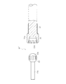
α=α1+α2
L1・sinα1=(L2−F)・sinα2+2F・sin(α2/2)
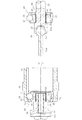
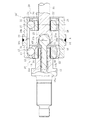
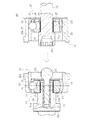
11 固定型継手部の内方部材(シャフト)
12 固定型継手部の内方部材(内輪)
13 ケージ
14 ボール
15 凸球面部
16 トラック溝
20 摺動型継手部(DOJ)
21 摺動型継手部の内方部材(シャフト)
22 摺動型継手部の内方部材(内輪)
23 ケージ
24 ボール
25 凹球面部
30,30’ 外方部材(外輪)
30a,30b 二部材
31,32 トラック溝
40,40’ 球対偶
50 アッセンブリ体
O 球対偶の球面中心
Claims (7)
- 円筒状外方部材を共通にしてその一端側に固定型継手部を配設すると共に他端側に摺動型継手部を配設し、前記固定型継手部の内方部材あるいは前記摺動型継手部の内方部材のいずれか一方の対向端部に凸球面部を設けると共に他方の対向端部に凹球面部を設け、前記凸球面部と凹球面部からなる球対偶を介して前記固定型継手部の内方部材と摺動型継手部の内方部材を、前記凸球面部あるいは凹球面部のいずれか一方が軸方向にスライド可能に連結し、前記固定型継手部と摺動型継手部の作動角を0°とした時、前記凸球面部と凹球面部からなる球対偶の球面中心から固定型継手部の継手中心までの距離L 1 と、前記球対偶の球面中心から摺動型継手部の継手中心までの距離L 2 とを、L 1 <L 2 の条件を満足するように設定したことを特徴とする摺動型等速自在継手。
- 前記固定型継手部は、前記外方部材と、球面状外周面に外方部材のトラック溝と対をなす複数のトラック溝を円周方向等間隔に軸方向に沿って形成した内方部材と、前記外方部材のトラック溝と内方部材のトラック溝との間に介在してトルクを伝達する複数のボールと、外方部材の球面状内周面と内方部材の球面状外周面との間に介在してボールを保持するケージとを備えた請求項1に記載の摺動型等速自在継手。
- 前記摺動型継手部は、前記外方部材と、球面状外周面に外方部材のトラック溝と対をなす複数のトラック溝を円周方向等間隔に軸方向に沿って形成した内方部材と、前記外方部材のトラック溝と内方部材のトラック溝との間に介在してトルクを伝達する複数のボールと、外方部材の円筒状内周面と内方部材の球面状外周面との間に介在してボールを保持するケージとを備え、前記ケージの球面状外周面の中心と球面状内周面の中心を、継手中心を挟んで等距離だけ軸方向にオフセットさせた請求項1に記載の摺動型等速自在継手。
- 前記外方部材は、固定型継手部側と摺動型継手部側の二部材で分割構成し、両部材を同軸的に突き合わせて接合一体化した請求項1〜3のいずれか一項に記載の摺動型等速自在継手。
- 前記球対偶は、嵌め合い構造の凸球面部と凹球面部からなり、前記凸球面部と凹球面部の相対回転による位相合わせでもって両者の係合離脱を可能とした請求項1〜4のいずれか一項に記載の摺動型等速自在継手。
- 円筒状外方部材を共通にしてその一端側に固定型継手部を配設した上で、摺動型継手部の内方部材の前記固定型継手部と対向する端部に凸球面部と凹球面部からなる球対偶を設けてアッセンブリ体とし、そのアッセンブリ体を前記円筒状外方部材の他端側から挿入し、前記摺動型継手部の内方部材に設けられた球対偶を固定型継手部の内方部材に、前記球対偶の凸球面部あるいは凹球面部のいずれか一方が軸方向にスライド可能に連結することを特徴とする摺動型等速自在継手の製造方法。
- 円筒状外方部材を固定型継手部側と摺動型継手部側の二部材で分割構成し、一方の部材に前記固定型継手部を配設すると共に他方の部材に前記摺動型継手部を配設した上で、前記固定型継手部の内方部材あるいは前記摺動型継手部の内方部材のいずれか一方の対向端部に設けられて位相に応じて係合離脱可能な構造の凸球面部と凹球面部からなる球対偶を、前記凸球面部あるいは凹球面部のいずれか一方が軸方向にスライド可能に連結した後、前記凸球面部と凹球面部が離脱不可な位相となるように外方部材の二部材を相対回転させた上で両部材を接合一体化することを特徴とする摺動型等速自在継手の製造方法。
Priority Applications (1)
| Application Number | Priority Date | Filing Date | Title |
|---|---|---|---|
| JP2005267130A JP4579112B2 (ja) | 2005-09-14 | 2005-09-14 | 摺動型等速自在継手及びその製造方法 |
Applications Claiming Priority (1)
| Application Number | Priority Date | Filing Date | Title |
|---|---|---|---|
| JP2005267130A JP4579112B2 (ja) | 2005-09-14 | 2005-09-14 | 摺動型等速自在継手及びその製造方法 |
Publications (2)
| Publication Number | Publication Date |
|---|---|
| JP2007078081A JP2007078081A (ja) | 2007-03-29 |
| JP4579112B2 true JP4579112B2 (ja) | 2010-11-10 |
Family
ID=37938622
Family Applications (1)
| Application Number | Title | Priority Date | Filing Date |
|---|---|---|---|
| JP2005267130A Expired - Fee Related JP4579112B2 (ja) | 2005-09-14 | 2005-09-14 | 摺動型等速自在継手及びその製造方法 |
Country Status (1)
| Country | Link |
|---|---|
| JP (1) | JP4579112B2 (ja) |
Families Citing this family (4)
| Publication number | Priority date | Publication date | Assignee | Title |
|---|---|---|---|---|
| KR101393591B1 (ko) | 2011-06-30 | 2014-05-12 | 남양공업주식회사 | 가변형 등속 조인트 |
| WO2014121832A1 (en) * | 2013-02-06 | 2014-08-14 | Gkn Driveline Deutschland Gmbh | Constant-velocity ball plunging plunging joint and arrangement having constant-velocity ball plunging joint |
| DE102016116149A1 (de) * | 2016-08-30 | 2018-03-01 | Dr. Ing. H.C. F. Porsche Aktiengesellschaft | Gelenkwelle mit einer Axialsicherung |
| KR102800829B1 (ko) * | 2024-10-29 | 2025-04-28 | 한세모빌리티 주식회사 | 듀얼 조인트 구조의 등속조인트 |
Family Cites Families (3)
| Publication number | Priority date | Publication date | Assignee | Title |
|---|---|---|---|---|
| FR2200923A5 (ja) * | 1972-06-01 | 1974-04-19 | Glaenzer Spicer Sa | |
| JPH01210619A (ja) * | 1988-02-17 | 1989-08-24 | Matsui Seisakusho:Kk | 自在継手 |
| JPH07269585A (ja) * | 1994-03-31 | 1995-10-17 | Ntn Corp | ダブルドラム形等速自在継手 |
-
2005
- 2005-09-14 JP JP2005267130A patent/JP4579112B2/ja not_active Expired - Fee Related
Also Published As
| Publication number | Publication date |
|---|---|
| JP2007078081A (ja) | 2007-03-29 |
Similar Documents
| Publication | Publication Date | Title |
|---|---|---|
| US7507161B2 (en) | Propshaft with constant velocity joint attachment | |
| JP2012017809A (ja) | 固定式等速自在継手 | |
| JP4541203B2 (ja) | トリポード型等速自在継手 | |
| CN101346552B (zh) | Bj型等速万向接头及其内侧部件 | |
| JP4579112B2 (ja) | 摺動型等速自在継手及びその製造方法 | |
| WO2015068536A1 (ja) | 固定式等速自在継手 | |
| JP2008256180A (ja) | 固定式等速自在継手及びその組立方法 | |
| JP4588591B2 (ja) | 固定型等速自在継手及びその製造方法 | |
| JP2009121667A (ja) | 摺動式等速自在継手 | |
| JP2008196591A (ja) | 固定式等速自在継手及びその製造方法 | |
| JP2007100797A (ja) | 摺動式等速自在継手 | |
| JP2010127311A (ja) | 固定式等速自在継手およびこれを用いた車輪軸受装置 | |
| JP2011069404A (ja) | 固定式等速自在継手 | |
| WO2023100522A1 (ja) | 摺動式等速自在継手 | |
| JP5133203B2 (ja) | 摺動式等速自在継手およびその製造方法 | |
| WO2017141731A1 (ja) | 固定式等速自在継手 | |
| JP5133206B2 (ja) | 摺動式等速自在継手およびその製造方法 | |
| JP4637723B2 (ja) | 摺動式等速自在継手 | |
| US20080064509A1 (en) | Fixed Type Constant Velocity Universal Joint | |
| JP2010249295A (ja) | 固定式等速自在継手およびその製造方法 | |
| JP2008175362A (ja) | 固定型等速自在継手 | |
| JP2010025207A (ja) | 等速自在継手 | |
| JP2010127312A (ja) | 摺動式等速自在継手およびこれを用いた車輪駆動装置 | |
| JP2009121661A (ja) | 固定式等速自在継手 | |
| US7097565B2 (en) | Fixed-center articulating constant velocity joint |
Legal Events
| Date | Code | Title | Description |
|---|---|---|---|
| A621 | Written request for application examination |
Free format text: JAPANESE INTERMEDIATE CODE: A621 Effective date: 20080805 |
|
| RD04 | Notification of resignation of power of attorney |
Free format text: JAPANESE INTERMEDIATE CODE: A7424 Effective date: 20091106 |
|
| A977 | Report on retrieval |
Free format text: JAPANESE INTERMEDIATE CODE: A971007 Effective date: 20100205 |
|
| A131 | Notification of reasons for refusal |
Free format text: JAPANESE INTERMEDIATE CODE: A131 Effective date: 20100209 |
|
| A521 | Request for written amendment filed |
Free format text: JAPANESE INTERMEDIATE CODE: A523 Effective date: 20100330 |
|
| TRDD | Decision of grant or rejection written | ||
| A01 | Written decision to grant a patent or to grant a registration (utility model) |
Free format text: JAPANESE INTERMEDIATE CODE: A01 Effective date: 20100811 |
|
| A01 | Written decision to grant a patent or to grant a registration (utility model) |
Free format text: JAPANESE INTERMEDIATE CODE: A01 |
|
| A61 | First payment of annual fees (during grant procedure) |
Free format text: JAPANESE INTERMEDIATE CODE: A61 Effective date: 20100825 |
|
| FPAY | Renewal fee payment (event date is renewal date of database) |
Free format text: PAYMENT UNTIL: 20130903 Year of fee payment: 3 |
|
| R150 | Certificate of patent or registration of utility model |
Free format text: JAPANESE INTERMEDIATE CODE: R150 |
|
| R250 | Receipt of annual fees |
Free format text: JAPANESE INTERMEDIATE CODE: R250 |
|
| R250 | Receipt of annual fees |
Free format text: JAPANESE INTERMEDIATE CODE: R250 |
|
| R250 | Receipt of annual fees |
Free format text: JAPANESE INTERMEDIATE CODE: R250 |
|
| R250 | Receipt of annual fees |
Free format text: JAPANESE INTERMEDIATE CODE: R250 |
|
| R250 | Receipt of annual fees |
Free format text: JAPANESE INTERMEDIATE CODE: R250 |
|
| LAPS | Cancellation because of no payment of annual fees |