JP4569944B2 - 検査のために部品を固定する方法及び装置 - Google Patents
検査のために部品を固定する方法及び装置 Download PDFInfo
- Publication number
- JP4569944B2 JP4569944B2 JP2003302331A JP2003302331A JP4569944B2 JP 4569944 B2 JP4569944 B2 JP 4569944B2 JP 2003302331 A JP2003302331 A JP 2003302331A JP 2003302331 A JP2003302331 A JP 2003302331A JP 4569944 B2 JP4569944 B2 JP 4569944B2
- Authority
- JP
- Japan
- Prior art keywords
- guide rail
- rail assembly
- clamp member
- clamp
- assembly
- Prior art date
- Legal status (The legal status is an assumption and is not a legal conclusion. Google has not performed a legal analysis and makes no representation as to the accuracy of the status listed.)
- Expired - Fee Related
Links
- 238000007689 inspection Methods 0.000 title claims description 12
- 238000000034 method Methods 0.000 title claims description 9
- 230000007246 mechanism Effects 0.000 claims description 20
- 230000008878 coupling Effects 0.000 description 5
- 238000010168 coupling process Methods 0.000 description 5
- 238000005859 coupling reaction Methods 0.000 description 5
- 230000000712 assembly Effects 0.000 description 4
- 238000000429 assembly Methods 0.000 description 4
- 230000008859 change Effects 0.000 description 3
- 238000004519 manufacturing process Methods 0.000 description 3
- 238000005259 measurement Methods 0.000 description 3
- 230000004048 modification Effects 0.000 description 2
- 238000012986 modification Methods 0.000 description 2
- 230000008439 repair process Effects 0.000 description 2
- 239000000523 sample Substances 0.000 description 2
- 238000005516 engineering process Methods 0.000 description 1
- 238000012423 maintenance Methods 0.000 description 1
- 230000008569 process Effects 0.000 description 1
- 239000007787 solid Substances 0.000 description 1
- 238000012360 testing method Methods 0.000 description 1
- 238000011144 upstream manufacturing Methods 0.000 description 1
Images


Classifications
-
- B—PERFORMING OPERATIONS; TRANSPORTING
- B25—HAND TOOLS; PORTABLE POWER-DRIVEN TOOLS; MANIPULATORS
- B25B—TOOLS OR BENCH DEVICES NOT OTHERWISE PROVIDED FOR, FOR FASTENING, CONNECTING, DISENGAGING OR HOLDING
- B25B5/00—Clamps
- B25B5/003—Combinations of clamps
-
- B—PERFORMING OPERATIONS; TRANSPORTING
- B25—HAND TOOLS; PORTABLE POWER-DRIVEN TOOLS; MANIPULATORS
- B25B—TOOLS OR BENCH DEVICES NOT OTHERWISE PROVIDED FOR, FOR FASTENING, CONNECTING, DISENGAGING OR HOLDING
- B25B5/00—Clamps
- B25B5/006—Supporting devices for clamps
Landscapes
- Engineering & Computer Science (AREA)
- Mechanical Engineering (AREA)
- Length Measuring Devices With Unspecified Measuring Means (AREA)
- A Measuring Device Byusing Mechanical Method (AREA)
- Automatic Assembly (AREA)
- Investigating Materials By The Use Of Optical Means Adapted For Particular Applications (AREA)
Description
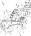
42 部品
44 バイアス機構
50 取付け組立体
52 案内レール組立体
54 第1のクランプ組立体
56 第2のクランプ組立体
174、212 固定クリップ
240 ハンドル
242、244 固定クリップとクランプ組立体との間のギャップ
260 位置合わせ装置
262、264 クランプ組立体の凹部域
Claims (7)
- 検査のために部品(42)を固定する方法であって、
案内レール組立体(52)に結合された第1のクランプ部材(54)と第2のクランプ部材(56)とを含む治具(40)を準備する段階を含み、
前記案内レール組立体(52)は、互いに連結され平行に延びる基部レール(104)と上部レール(100)と該基部及び上部レール間の中央レール(102)とから形成され、該中央レール(102)が前記基部及び上部レールよりも狭い幅を有しており、
前記第1のクランプ部材を、前記上部レールから垂直に延びるように且つ前記案内レール組立体に対して定位置となるように、前記案内レール組立体(52)を貫通して延びる締結具(136)によって前記案内レール組立体に固定する段階と、
前記第2のクランプ部材(56)を、該第2のクランプ部材に設けられた垂直方向に延びる2つの脚部(190、192)と、該脚部の各々から水平方向に延びて前記基部及び上部レール間で前記中央レール(102)に沿って摺動可能に結合されるフーチング部(194、196)とによって、該第2のクランプ部材が前記第1のクランプ部材に対してほぼ平行になるように、摺動可能に前記案内レール組立体に結合する段階と、
スプリング(230)により互いに離れるように付勢された1対のヒンジ付きアーム(222、224)を含むバイアス機構(44)を用い、前記スプリングを弛緩状態として該バイアス機構の一部を前記上部レールの上面(120)に付勢させて摩擦係合させることにより、前記第2のクランプ部材を前記案内レール組立体(52)に対して結合させて前記第1と第2のクランプ部材の間で前記治具内に前記部品を固定する段階と、
を含むことを特徴とする方法。 - 前記第1と第2のクランプ部材(54、56)の間で前記治具(40)内に前記部品(42)を固定する段階が、各クランプ部材から延びる位置合わせ機構(260)を使用して、前記部品を基準点に対して位置合わせする段階を更に含むことを特徴とする、請求項1に記載の方法。
- 前記第1と第2のクランプ部材(54、56)の間で前記治具(40)内に前記部品(42)を固定する段階が、
前記第2のクランプ部材を、前記案内レール組立体に沿って、該案内レール組立体を通って延びる中心対称軸線とほぼ平行な方向に摺動させる段階と、
前記第1及び第2のクランプ部材が備える、前記案内レール組立体の中心対称軸線対してほぼ垂直な方向に該案内レール組立体から離れるように移動して前記第1及び第2のクランプ部材にギャップ(242、244)を形成するクリップ(174、212)を用いて、前記ギャップを前記部品(42)の厚さ(t1)適合するように変化させて該部品を固定する段階と、
を更に含むことを特徴とする、請求項1に記載の方法。 - 中心対称軸線を含み、互いに連結され平行に延びる基部レール(104)と上部レール(100)と該基部及び上部レール間の中央レール(102)とから形成された案内レール組立体(52)であって、前記中央レール(102)が前記基部及び上部レールよりも狭い幅を有している案内レール組立体(52)と、
前記案内レール組立体から外向きに延びる第1のクランプ部材(54)と、
前記案内レール組立体から外向きに延びる第2のクランプ部材(56)と、を含み、
前記第1のクランプ部材は、前記上部レールから垂直に延びるように且つ前記案内レール組立体に対して定位置となるように、前記案内レール組立体(52)を貫通して延びる締結具(136)によって前記案内レール組立体に固定されており、
前記第2のクランプ部材は、垂直方向に延びる2つの脚部(190、192)と、該脚部の各々から水平方向に延びて前記基部及び上部レール間で前記中央レール(102)に沿って摺動可能に結合されるフーチング部(194、196)とを備え、該第2のクランプ部材が前記第1のクランプ部材に対してほぼ平行になるように、前記案内レール組立体に摺動可能に結合され、
前記第1及び第2のクランプ部材が、それらの間に部品(42)を保持するように構成されており、
前記第2のクランプ部材が、スプリング(230)により互いに離れるように付勢された1対のヒンジ付きアーム(222、224)を含むバイアス機構(44)を含み、前記スプリングを弛緩状態として該バイアス機構の一部を前記上部レールの上面(120)に付勢させて摩擦係合させることにより、前記第2のクランプ部材を前記案内レール組立体(52)に対して結合させて前記第1と第2のクランプ部材の間で前記治具内に前記部品を固定することを特徴とする治具(40)。 - 前記第1のクランプ部材(54)が、前記第2のクランプ部材(56)に対向しかつ該第2のクランプ部材とほぼ平行であることを特徴とする、請求項4に記載の治具(40)。
- 前記第1及び第2のクランプ部材(54、56)の少なくとも1つが、基準点に対して位置合わせされた状態で部品(42)を位置決めするように構成された位置合わせ機構(260)を含むことを特徴とする、請求項4に記載の治具(40)。
- 前記第1及び第2のクランプ部材(54、56)の各々が、保持部材(212)を含み、該保持部材の各々が、その中に部品(42)の一部分を受けるように選択的に調節可能であることを特徴とする、請求項4に記載の治具(40)。
Applications Claiming Priority (1)
| Application Number | Priority Date | Filing Date | Title |
|---|---|---|---|
| US10/229,692 US6931751B2 (en) | 2002-08-28 | 2002-08-28 | Methods and apparatus for securing components for inspection |
Publications (3)
| Publication Number | Publication Date |
|---|---|
| JP2004085571A JP2004085571A (ja) | 2004-03-18 |
| JP2004085571A5 JP2004085571A5 (ja) | 2006-10-05 |
| JP4569944B2 true JP4569944B2 (ja) | 2010-10-27 |
Family
ID=31495357
Family Applications (1)
| Application Number | Title | Priority Date | Filing Date |
|---|---|---|---|
| JP2003302331A Expired - Fee Related JP4569944B2 (ja) | 2002-08-28 | 2003-08-27 | 検査のために部品を固定する方法及び装置 |
Country Status (3)
| Country | Link |
|---|---|
| US (1) | US6931751B2 (ja) |
| EP (1) | EP1394505A3 (ja) |
| JP (1) | JP4569944B2 (ja) |
Families Citing this family (7)
| Publication number | Priority date | Publication date | Assignee | Title |
|---|---|---|---|---|
| FR2853056B1 (fr) * | 2003-03-28 | 2005-07-15 | Snecma Moteurs | Dispositif et procede de mesure de profil |
| US7752755B2 (en) * | 2005-10-14 | 2010-07-13 | General Electric Company | Methods and apparatus for manufacturing components |
| US8051564B2 (en) * | 2007-01-09 | 2011-11-08 | General Electric Company | Methods and apparatus for fabricating a turbine nozzle assembly |
| US7862264B2 (en) * | 2007-02-27 | 2011-01-04 | General Electric Company | Method and apparatus to secure a component in position for fabrication |
| ITCO20130063A1 (it) * | 2013-11-28 | 2015-05-29 | Nuovo Pignone Srl | Strumento per misurare l'angolo di impilamento radiale di pale, metodo di misura e pala. |
| US9316493B2 (en) * | 2013-12-13 | 2016-04-19 | Siemens Energy, Inc. | Method and apparatus for determining gas turbine dampening cone inner diameter |
| CN104501709A (zh) * | 2014-11-24 | 2015-04-08 | 重庆光荣摩托车配件有限公司 | 摩托车前挡泥板变形检测装置 |
Citations (3)
| Publication number | Priority date | Publication date | Assignee | Title |
|---|---|---|---|---|
| JPH0224309U (ja) * | 1988-07-29 | 1990-02-19 | ||
| JP2000176766A (ja) * | 1998-12-17 | 2000-06-27 | United Technol Corp <Utc> | ブランク部材保持用取付具及びブランク部材を取り付ける方法 |
| JP2001311601A (ja) * | 2000-04-28 | 2001-11-09 | Daihatsu Motor Co Ltd | パネル状製品の形状測定用基準治具 |
Family Cites Families (28)
| Publication number | Priority date | Publication date | Assignee | Title |
|---|---|---|---|---|
| FR472204A (fr) * | 1914-05-14 | 1914-11-26 | Frederic Jules Elie Nazat | Presse à cheviller les portes |
| US1811518A (en) * | 1929-09-28 | 1931-06-23 | George E Palmer | Clamp |
| US3150870A (en) * | 1961-03-17 | 1964-09-29 | John W Nelson | Clamping tool |
| US3758100A (en) * | 1970-03-23 | 1973-09-11 | D Taylor | Clamping devices |
| US4333239A (en) | 1980-06-02 | 1982-06-08 | United Technologies Corporation | Method and apparatus for inspecting shrouds of rotor blades |
| GB8430398D0 (en) | 1984-12-01 | 1985-01-09 | Sigma Ltd | Component measuring apparatus |
| DE3690033T1 (ja) * | 1985-01-22 | 1987-04-02 | ||
| US4691905A (en) * | 1985-04-18 | 1987-09-08 | Nissan Motor Co., Ltd. | Machine for holding workpiece |
| US4805505A (en) * | 1988-03-02 | 1989-02-21 | John Cantlin | Multi-stop |
| US4905745A (en) * | 1989-04-25 | 1990-03-06 | Jaeger Waldemar A | Woodcutting guide |
| US5167405A (en) * | 1991-08-21 | 1992-12-01 | Midaco Corporation | Fast change set-up device for work on work support |
| JP2705850B2 (ja) * | 1992-07-20 | 1998-01-28 | ハーバート メイスン,ジェイムズ | 車両用アラインメント測定装置 |
| US5343627A (en) * | 1993-05-24 | 1994-09-06 | Hesseltine Dennis R | Method and means for measuring squareness of plate structures |
| DE4327861A1 (de) * | 1993-08-19 | 1995-02-23 | Bessey & Sohn | Spanneinrichtung |
| US5299609A (en) * | 1993-09-10 | 1994-04-05 | Wedler Richard L | Precision adjustable router fence |
| US5637838A (en) * | 1994-08-03 | 1997-06-10 | Arey; Clyde D. | Apparatus for measuring, weighing and counting fish |
| JP3178978B2 (ja) * | 1994-10-24 | 2001-06-25 | 株式会社イマオコーポレーション | 取付補助部材 |
| US5575145A (en) | 1994-11-01 | 1996-11-19 | Chevron U.S.A. Inc. | Gas turbine repair |
| US5593085A (en) | 1995-03-22 | 1997-01-14 | Solar Turbines Incorporated | Method of manufacturing an impeller assembly |
| JP3129936B2 (ja) * | 1995-06-12 | 2001-01-31 | 矢崎総業株式会社 | グロメット止水方法及びグロメット止水用治具 |
| US5711083A (en) * | 1995-09-11 | 1998-01-27 | Bidwell Corporation | Gage set for measuring inside and outside diameters of ring-shaped parts |
| JP3540474B2 (ja) | 1995-11-11 | 2004-07-07 | 株式会社ソディック | ワイヤ放電加工装置の基準接触位置の位置決め方法及びその装置 |
| US6073360A (en) * | 1997-01-22 | 2000-06-13 | Js Research And Development, Inc. | Instrument mount with spring-loaded clamp |
| US5954322A (en) * | 1997-07-16 | 1999-09-21 | Boria; Thomas J. | Elevation fixture for a machine tool |
| US6068541A (en) * | 1997-12-22 | 2000-05-30 | United Technologies Corporation | Method for using a fixture enabling more accurate machining of a part |
| US6442857B1 (en) * | 2000-11-10 | 2002-09-03 | Toto Ltd. | Portable surface inspector |
| US6409471B1 (en) | 2001-02-16 | 2002-06-25 | General Electric Company | Shroud assembly and method of machining same |
| US6745804B2 (en) * | 2001-07-11 | 2004-06-08 | Black & Decker Inc. | Portable work bench |
-
2002
- 2002-08-28 US US10/229,692 patent/US6931751B2/en not_active Expired - Fee Related
-
2003
- 2003-08-27 EP EP03255312A patent/EP1394505A3/en not_active Withdrawn
- 2003-08-27 JP JP2003302331A patent/JP4569944B2/ja not_active Expired - Fee Related
Patent Citations (3)
| Publication number | Priority date | Publication date | Assignee | Title |
|---|---|---|---|---|
| JPH0224309U (ja) * | 1988-07-29 | 1990-02-19 | ||
| JP2000176766A (ja) * | 1998-12-17 | 2000-06-27 | United Technol Corp <Utc> | ブランク部材保持用取付具及びブランク部材を取り付ける方法 |
| JP2001311601A (ja) * | 2000-04-28 | 2001-11-09 | Daihatsu Motor Co Ltd | パネル状製品の形状測定用基準治具 |
Also Published As
| Publication number | Publication date |
|---|---|
| US20050076523A1 (en) | 2005-04-14 |
| EP1394505A2 (en) | 2004-03-03 |
| JP2004085571A (ja) | 2004-03-18 |
| EP1394505A3 (en) | 2008-12-03 |
| US6931751B2 (en) | 2005-08-23 |
Similar Documents
| Publication | Publication Date | Title |
|---|---|---|
| JP4572403B2 (ja) | 部品を検査のために位置合わせする方法及び装置 | |
| JP2010527438A (ja) | バケットzノッチ位置の測定用検査ツール | |
| JP4569944B2 (ja) | 検査のために部品を固定する方法及び装置 | |
| US7578164B2 (en) | Method and apparatus for inspecting turbine nozzle segments | |
| KR880013176A (ko) | 가압수 원자로의 증기 발생기의 완전 교체방법 | |
| CN103673819A (zh) | 复合式排气管总成多元化利用检具 | |
| CN111006572A (zh) | 零件轮廓检测装置 | |
| CN203731973U (zh) | 复合式排气管总成多元化利用检具 | |
| CN210268487U (zh) | 一种锁板轮廓度检具 | |
| KR102015566B1 (ko) | 판형 핵연료 검사용 고정지그 및 이를 이용한 판형 핵연료 검사 방법 | |
| CN112497122A (zh) | 换挡拨叉组件防错装配夹具 | |
| CN205537403U (zh) | 一种汽车边梁用检具 | |
| CN115143860B (zh) | 风扇叶片叶尖圆弧测具及测试方法 | |
| CN219798128U (zh) | 一种汽车转向管柱质量检查装置 | |
| CN210242624U (zh) | 一种踏板后连接支架检具 | |
| CN220568022U (zh) | 一种圆跳动手动检测工装 | |
| CN220341168U (zh) | 一种用于改善晶圆直径量测方式与准确性的装置 | |
| KR102560005B1 (ko) | 정밀부품 검사용 지그 및 이를 이용한 검사방법 | |
| CN207472155U (zh) | 一种轴类零件凹槽位置尺寸检测装置 | |
| CN219640909U (zh) | 一种特制xyz三向位置度检测夹具 | |
| CN221037225U (zh) | 一种柔性汽车白车身左右前大梁总成检具 | |
| CN219694046U (zh) | 一种快速检验热管检具 | |
| KR200248448Y1 (ko) | 엘보우 길이 측정기 | |
| CN212568870U (zh) | 一种轨道式ict检测机产品定位机构 | |
| KR100353983B1 (ko) | 머플러 플랜지 설치 각도 검사용 지그 |
Legal Events
| Date | Code | Title | Description |
|---|---|---|---|
| A521 | Request for written amendment filed |
Free format text: JAPANESE INTERMEDIATE CODE: A523 Effective date: 20060818 |
|
| A621 | Written request for application examination |
Free format text: JAPANESE INTERMEDIATE CODE: A621 Effective date: 20060818 |
|
| A977 | Report on retrieval |
Free format text: JAPANESE INTERMEDIATE CODE: A971007 Effective date: 20090205 |
|
| A131 | Notification of reasons for refusal |
Free format text: JAPANESE INTERMEDIATE CODE: A131 Effective date: 20090519 |
|
| A601 | Written request for extension of time |
Free format text: JAPANESE INTERMEDIATE CODE: A601 Effective date: 20090812 |
|
| RD02 | Notification of acceptance of power of attorney |
Free format text: JAPANESE INTERMEDIATE CODE: A7422 Effective date: 20090812 |
|
| RD04 | Notification of resignation of power of attorney |
Free format text: JAPANESE INTERMEDIATE CODE: A7424 Effective date: 20090812 |
|
| A602 | Written permission of extension of time |
Free format text: JAPANESE INTERMEDIATE CODE: A602 Effective date: 20090818 |
|
| A521 | Request for written amendment filed |
Free format text: JAPANESE INTERMEDIATE CODE: A523 Effective date: 20091116 |
|
| A131 | Notification of reasons for refusal |
Free format text: JAPANESE INTERMEDIATE CODE: A131 Effective date: 20091222 |
|
| A601 | Written request for extension of time |
Free format text: JAPANESE INTERMEDIATE CODE: A601 Effective date: 20100318 |
|
| A602 | Written permission of extension of time |
Free format text: JAPANESE INTERMEDIATE CODE: A602 Effective date: 20100324 |
|
| A521 | Request for written amendment filed |
Free format text: JAPANESE INTERMEDIATE CODE: A523 Effective date: 20100621 |
|
| TRDD | Decision of grant or rejection written | ||
| A01 | Written decision to grant a patent or to grant a registration (utility model) |
Free format text: JAPANESE INTERMEDIATE CODE: A01 Effective date: 20100713 |
|
| A01 | Written decision to grant a patent or to grant a registration (utility model) |
Free format text: JAPANESE INTERMEDIATE CODE: A01 |
|
| A61 | First payment of annual fees (during grant procedure) |
Free format text: JAPANESE INTERMEDIATE CODE: A61 Effective date: 20100804 |
|
| FPAY | Renewal fee payment (event date is renewal date of database) |
Free format text: PAYMENT UNTIL: 20130820 Year of fee payment: 3 |
|
| R150 | Certificate of patent or registration of utility model |
Free format text: JAPANESE INTERMEDIATE CODE: R150 |
|
| LAPS | Cancellation because of no payment of annual fees |