JP4467677B2 - Game machine - Google Patents
Game machine Download PDFInfo
- Publication number
- JP4467677B2 JP4467677B2 JP25635799A JP25635799A JP4467677B2 JP 4467677 B2 JP4467677 B2 JP 4467677B2 JP 25635799 A JP25635799 A JP 25635799A JP 25635799 A JP25635799 A JP 25635799A JP 4467677 B2 JP4467677 B2 JP 4467677B2
- Authority
- JP
- Japan
- Prior art keywords
- command
- display
- control
- game
- output
- Prior art date
- Legal status (The legal status is an assumption and is not a legal conclusion. Google has not performed a legal analysis and makes no representation as to the accuracy of the status listed.)
- Expired - Fee Related
Links
Images


Landscapes
- Pinball Game Machines (AREA)
Description
【0001】
【発明の属する技術分野】
本発明は、遊技者の操作に応じて遊技が行われるパチンコ遊技機やコイン遊技機等の遊技機に関し、特に、遊技盤における遊技領域において遊技者の操作に応じて遊技が行われる遊技機に関する。
【0002】
【従来の技術】
遊技機として、表示状態が変化可能な可変表示部を有する可変表示装置が設けられ、可変表示部の表示結果があらかじめ定められた特定の表示態様となった場合に遊技者に有利となる大当り遊技状態に移行するように構成されたものがある。可変表示装置には複数の可変表示部があり、通常、複数の可変表示部の表示結果を時期を異ならせて表示するように構成されている。可変表示部には、例えば、図柄等の複数の識別情報が可変表示される。可変表示部の表示結果があらかじめ定められた特定の表示態様の組合せとなることを、通常、「大当り」という。なお、遊技価値とは、遊技機の遊技領域に設けられた可変入賞球装置の状態が打球が入賞しやすい遊技者にとって有利な状態になることや、遊技者にとって有利な状態となるための権利を発生させたりすることである。
【0003】
大当りが発生すると、例えば、大入賞口が所定回数開放して打球が入賞しやすい大当り遊技状態に移行する。そして、各開放期間において、所定個(例えば10個)の大入賞口への入賞があると大入賞口は閉成する。そして、大入賞口の開放回数は、所定回数(例えば16ラウンド)に固定されている。なお、各開放について開放時間(例えば29.5秒)が決められ、入賞数が所定個に達しなくても開放時間が経過すると大入賞口は閉成する。また、大入賞口が閉成した時点で所定の条件(例えば、大入賞口内に設けられているVゾーンへの入賞)が成立していない場合には、所定回数に達していなくても大当り遊技状態は終了する。
【0004】
また、「大当り」の組合せ以外の「はずれ」の表示態様の組合せのうち、複数の可変表示部の表示結果のうちの一部が未だに導出表示されていない段階において、既に表示結果が導出表示されている可変表示部の表示態様が特定の表示態様の組合せとなる表示条件を満たしている状態を「リーチ」という。遊技者は、大当りをいかにして発生させるかを楽しみつつ遊技を行う。
【0005】
遊技機における遊技進行はマイクロコンピュータ等による遊技制御手段によって制御される。可変表示装置に表示される識別情報、キャラクタ画像および背景画像は、遊技制御手段からの制御コマンドに従って動作する表示制御手段によって制御される。従って、遊技の進行を制御する遊技制御手段は、表示制御手段に対して表示制御のためのコマンドを送信する必要がある。
【0006】
また、遊技盤にはランプやLED等の発光体が設けられ、遊技効果を増進するために遊技の進行に伴ってそれらの発光体が点灯されたり消灯されたりする。発光体の点灯や滅灯は、遊技制御手段によって制御されたり、遊技制御手段からの制御コマンドを受信する発光体制御手段によって制御されている。さらに、遊技盤にはスピーカが設けられ、遊技効果を増進するために遊技の進行に伴ってスピーカから種々の効果音が発せられる。音発生は、遊技制御手段によって制御されたり、遊技制御手段からの制御コマンドを受信する音制御手段によって制御されている。
【0007】
一般に、発光体の点灯/消灯パターンの切り替えタイミング制御および効果音パターンの切り替え制御は、遊技の進行を制御する遊技制御手段によって行われる。従って、遊技制御手段とは別の発光体制御手段や音制御手段が設けられている場合には、遊技制御手段は、遊技の進行に伴って、発光体制御手段および音制御手段に制御コマンドを送信する必要がある。
【0008】
【発明が解決しようとする課題】
従来の遊技機は以上のように構成されているので、遊技制御手段は、遊技制御を行っているときに、表示制御手段、発光体制御手段および音制御手段のそれぞれに対して制御コマンドを送る必要がある。従って、遊技制御手段の制御コマンド送出に要する負担が重く、本来の遊技制御のために費やすことができる処理時間が制限されるという課題がある。
【0009】
そこで、本発明は、遊技制御手段の他の制御手段に対する制御コマンド送出に要する負担を軽減することができる遊技機を提供することを目的とする。
【0010】
【課題を解決するための手段】
本発明による遊技機は、表示状態が変化可能な複数の表示領域を有する可変表示部を含み、変動開始の条件の成立に応じて表示領域に表示される識別情報の変動を開始し、識別情報の表示結果があらかじめ定められた特定表示態様となったときに遊技者に有利な大当り遊技状態に制御可能な遊技機であって、遊技の進行を制御する遊技制御手段を有する主基板と、遊技演出用の装置を用いた演出内容を決定する演出制御手段を有する演出制御基板と、可変表示部の表示制御を行う表示制御手段を有する表示制御基板とを備え、遊技制御手段は、遊技進行に応じて遊技状態を特定可能なコマンドを出力する遊技制御側コマンド出力手段を含み、遊技制御側コマンド出力手段は、演出制御手段に、遊技状態を特定可能なコマンドとして、識別情報の変動開始の条件の成立に応じて、識別情報の変動を開始させるときにのみ可変表示部における識別情報の変動時間を特定するためのコマンドを出力するとともに、識別情報の変動時間が経過したときに全識別情報の停止を示すコマンドを出力し、演出制御手段は、遊技制御手段から出力された遊技状態を特定可能なコマンドに対応して制御コマンドを表示制御手段に出力する演出制御側コマンド出力手段と、遊技制御手段から出力された遊技状態を特定可能なコマンドが示す遊技状態に対応する演出内容を決定する演出内容決定手段とを含み、演出制御側コマンド出力手段は、演出内容決定手段が決定した演出内容に応じた制御コマンドを作成して表示制御手段に出力可能であり、表示制御手段は、識別情報の変動時間を特定するためのコマンドに対応して演出制御側コマンド出力手段から出力された制御コマンドにもとづいて、可変表示部において識別情報の変動表示を開始させる変動表示開始手段と、全識別情報の停止を示すコマンドに対応して演出制御側コマンド出力手段から出力された制御コマンドにもとづいて、可変表示部において識別情報の変動表示を停止させる停止制御手段とを含み、演出内容決定手段は、遊技制御手段から出力された遊技状態を特定可能なコマンドに応じて、大当り遊技状態の発生の可能性が高いことを報知するための大当り予告演出の内容を独自に決定し、演出制御側コマンド出力手段は、演出内容決定手段が大当り予告演出の内容を決定した場合に、識別情報の変動時間を特定するためのコマンドに対応して出力する制御コマンドに演出内容決定手段が決定した大当り予告演出の内容に対応する情報を含めた制御コマンドを出力することを特徴とする。
本発明による他の態様の遊技機は、表示状態が変化可能な複数の表示領域を有する可変表示部を含み、変動開始の条件の成立に応じて表示領域に表示される識別情報の変動を開始し、識別情報の表示結果があらかじめ定められた特定表示態様となったときに遊技者に有利な大当り遊技状態に制御可能な遊技機であって、遊技の進行を制御する遊技制御手段を有する主基板と、遊技演出用の装置を用いた演出内容を決定する演出制御手段を有する演出制御基板と、可変表示部の表示制御を行う表示制御手段を有する表示制御基板とを備え、遊技制御手段は、遊技進行に応じて遊技状態を特定可能なコマンドを出力する遊技制御側コマンド出力手段を含み、遊技制御側コマンド出力手段は、演出制御手段に、遊技状態を特定可能なコマンドとして、識別情報の変動開始の条件の成立に応じて、識別情報の変動を開始させるときにのみ可変表示部における識別情報の変動時間を特定するためのコマンドを出力するとともに、識別情報の変動時間が経過したときに全識別情報の停止を示すコマンドを出力し、演出制御手段は、遊技制御手段から出力された遊技状態を特定可能なコマンドに対応して制御コマンドを表示制御手段に出力する演出制御側コマンド出力手段と、遊技制御手段から出力された遊技状態を特定可能なコマンドが示す遊技状態に対応する演出内容を決定する演出内容決定手段とを含み、演出制御側コマンド出力手段は、演出内容決定手段が決定した演出内容に応じた制御コマンドを作成して表示制御手段に出力可能であり、表示制御手段は、識別情報の変動時間を特定するためのコマンドに対応して演出制御側コマンド出力手段から出力された制御コマンドにもとづいて、可変表示部において識別情報の変動表示を開始させる変動表示開始手段と、全識別情報の停止を示すコマンドに対応して演出制御側コマンド出力手段から出力された制御コマンドにもとづいて、可変表示部において識別情報の変動表示を停止させる停止制御手段とを含み、演出内容決定手段は、遊技制御手段から出力された遊技状態を特定可能なコマンドに応じて、大当り遊技状態の発生の可能性が高いことを報知するための大当り予告演出の内容を独自に決定し、演出制御側コマンド出力手段は、演出内容決定手段が大当り予告演出の内容を決定した場合に、識別情報の変動時間を特定するためのコマンドに対応して出力する制御コマンドとは別個に演出内容決定手段が決定した大当り予告演出の内容に対応する情報を含む制御コマンドを出力することを特徴とする。
【0022】
【発明の実施の形態】
以下、本発明の一実施形態を図面を参照して説明する。
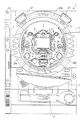
まず、遊技機の一例であるパチンコ遊技機の全体の構成について説明する。図1はパチンコ遊技機1を正面からみた正面図、図2はパチンコ遊技機1の内部構造を示す全体背面図、図3はパチンコ遊技機1の遊技盤を背面からみた背面図である。なお、ここでは、遊技機の一例としてパチンコ遊技機を示すが、本発明はパチンコ遊技機に限られず、例えばコイン遊技機等であってもよい。また、画像式の遊技機やスロット機に適用することもできる。
【0023】
図1に示すように、パチンコ遊技機1は、額縁状に形成されたガラス扉枠2を有する。ガラス扉枠2の下部表面には打球供給皿3がある。打球供給皿3の下部には、打球供給皿3からあふれた景品玉を貯留する余剰玉受皿4と打球を発射する打球操作ハンドル(操作ノブ)5が設けられている。ガラス扉枠2の後方には、遊技盤6が着脱可能に取り付けられている。また、遊技盤6の前面には遊技領域7が設けられている。
【0024】
遊技領域7の中央付近には、複数種類の図柄を可変表示するための可変表示部(特別図柄表示部)9と7セグメントLEDによる可変表示器(普通図柄表示器)10とを含む可変表示装置8が設けられている。また、可変表示器10の下部には、4個のLEDからなる通過記憶表示器(普通図柄用記憶表示器)41が設けられている。この実施の形態では、可変表示部9には、「左」、「中」、「右」の3つの図柄表示エリアがある。可変表示装置8の側部には、打球を導く通過ゲート11が設けられている。この例では、4個を上限として、通過ゲート11の玉通過がある毎に、通過記憶表示器41は点灯しているLEDを1つずつ増やす。そして、可変表示器10の普通図柄の可変表示が開始される毎に、点灯しているLEDを1つ減らす。
【0025】
通過ゲート11を通過した打球は、玉出口13を経て始動入賞口14の方に導かれる。通過ゲート11と玉出口13との間の通路には、通過ゲート11を通過した打球を検出するゲートスイッチ12がある。また、始動入賞口14に入った入賞球は、遊技盤6の背面に導かれ、始動口スイッチ17によって検出される。また、始動入賞口14の下部には開閉動作を行う可変入賞球装置15が設けられている。可変入賞球装置15は、ソレノイド16によって開状態とされる。
【0026】
可変入賞球装置15の下部には、特定遊技状態(大当り状態)においてソレノイド21によって開状態とされる開閉板20が設けられている。この実施の形態では、開閉板20が大入賞口を開閉する手段となる。開閉板20から遊技盤6の背面に導かれた入賞球のうち一方(Vゾーン)に入った入賞球はVカウントスイッチ22で検出される。また、開閉板20からの入賞球はカウントスイッチ23で検出される。可変表示装置8の下部には、始動入賞口14に入った入賞球数の記憶数を表示する4個のLEDを有する始動入賞記憶表示器(特別図柄用記憶表示器)18が設けられている。この例では、4個を上限として、始動入賞がある毎に、始動入賞記憶表示器18は点灯しているLEDを1つずつ増やす。そして、可変表示部9の特別図柄の可変表示が開始される毎に、点灯しているLEDを1つ減らす。
【0027】
遊技盤6には、複数の入賞口19,24が設けられている。遊技領域7の左右周辺には、遊技中に点滅表示される装飾ランプ25が設けられ、下部には、入賞しなかった打球を吸収するアウト口26がある。また、遊技領域7の外側の左右上部には、効果音を発する2つのスピーカ27が設けられている。遊技領域7の外周には、遊技効果LED28aおよび遊技効果ランプ28b,28cが設けられている。そして、この例では、一方のスピーカ27の近傍に、景品玉払出時に点灯する賞球ランプ51が設けられ、他方のスピーカ27の近傍に、補給玉が切れたときに点灯する玉切れランプ52が設けられている。さらに、図1には、パチンコ遊技台1に隣接して設置され、プリペイドカードが挿入されることによって玉貸しを可能にするカードユニット50も示されている。
【0028】
打球発射装置から発射された打球は、打球レールを通って遊技領域7に入り、その後、遊技領域7を下りてくる。打球が通過ゲート11を通ってゲートスイッチ12で検出されると、可変表示器10の表示数字が連続的に変化する状態になる。また、打球が始動入賞口14に入り始動口スイッチ17で検出されると、図柄の変動を開始できる状態であれば、可変表示部9内の図柄が回転を始める。図柄の変動を開始できる状態でなければ、始動入賞記憶を1増やす。
【0029】
可変表示部9内の画像の回転は、一定時間が経過したときに停止する。停止時の画像の組み合わせが大当り図柄の組み合わせであると、大当り遊技状態に移行する。すなわち、開閉板20が、一定時間経過するまで、または、所定個数(例えば10個)の打球が入賞するまで開放する。そして、開閉板20の開放中に打球が特定入賞領域に入賞しVカウントスイッチ22で検出されると、継続権が発生し開閉板20の開放が再度行われる。この継続権の発生は、所定回数(例えば15ラウンド)許容される。
【0030】
停止時の可変表示部9内の画像の組み合わせが確率変動を伴う大当り図柄の組み合わせである場合には、次に大当りとなる確率が高くなる。すなわち、高確率状態という遊技者にとってさらに有利な状態となる。また、可変表示器10における停止図柄が所定の図柄(当り図柄)である場合に、可変入賞球装置15が所定時間だけ開状態になる。さらに、高確率状態では、可変表示器10における停止図柄が当り図柄になる確率が高められるとともに、可変入賞球装置15の開放時間と開放回数が高められる。
【0031】
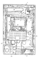
次に、パチンコ遊技機1の裏面の構造について図2を参照して説明する。
可変表示装置8の背面では、図2に示すように、機構板36の上部に景品玉タンク38が設けられ、パチンコ遊技機1が遊技機設置島に設置された状態でその上方から景品玉が景品玉タンク38に供給される。景品玉タンク38内の景品玉は、誘導樋39を通って玉払出装置に至る。
【0032】
機構板36には、中継基板30を介して可変表示部9を制御する可変表示制御ユニット29、基板ケース32に覆われ遊技制御用マイクロコンピュータ等が搭載された遊技制御基板(主基板)31、可変表示制御ユニット29と遊技制御基板31との間の信号を中継するための中継基板33、および景品玉の払出制御を行う払出制御用マイクロコンピュータ等が搭載された賞球基板37が設置されている。さらに、機構板36には、モータの回転力を利用して打球を遊技領域7に発射する打球発射装置34と、スピーカ27および遊技効果ランプ・LED28a,28b,28cに信号を送るためのランプ制御基板35が設置されている。
【0033】
また、図3はパチンコ遊技機1の遊技盤を背面からみた背面図である。遊技盤6の裏面には、図3に示すように、各入賞口および入賞球装置に入賞した入賞玉を所定の入賞経路に沿って導く入賞玉集合カバー40が設けられている。入賞玉集合カバー40に導かれる入賞玉のうち、開閉板20を経て入賞したものは、玉払出装置97が相対的に多い景品玉数(例えば15個)を払い出すように制御される。始動入賞口14を経て入賞したものは、玉払出装置(図3において図示せず)が相対的に少ない景品玉数(例えば6個)を払い出すように制御される。そして、その他の入賞口24および入賞球装置を経て入賞したものは、玉払出装置が相対的に中程度の景品玉数(例えば10個)を払い出すように制御される。なお、図3には、中継基板33が例示されている。
【0034】
賞球払出制御を行うために、入賞球検出スイッチ99、始動口スイッチ17およびカウントスイッチ23からの信号が、主基板31に送られる。主基板31に入賞球検出スイッチ99のオン信号が送られると、主基板31から賞球基板37に賞球個数信号が送られる。入賞があったことは入賞球検出スイッチ99で検出されるが、その場合に、主基板31から、賞球基板37に賞球個数信号が与えられる。例えば、始動口スイッチ17のオンに対応して入賞球検出スイッチ99がオンすると、賞球個数信号に「6」が出力され、カウントスイッチ23またはVカウントスイッチ22のオンに対応して入賞球検出スイッチ99がオンすると、賞球個数信号に「15」が出力される。そして、それらのスイッチがオンしない場合に入賞球検出スイッチ99がオンすると、賞球個数信号に「10」が出力される。
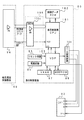
【0035】
図4は、主基板31における回路構成の一例を示すブロック図である。なお、図4には、賞球基板37、ランプ制御基板(発光体制御基板)35、音制御基板70、表示制御基板80および総合演出制御基板90も示されている。主基板31には、プログラムに従ってパチンコ遊技機1を制御する基本回路53と、ゲートスイッチ12、始動口スイッチ17、Vカウントスイッチ22、カウントスイッチ23および入賞球検出スイッチ99からの信号を基本回路53に与えるスイッチ回路58と、可変入賞球装置15を開閉するソレノイド16および開閉板20を開閉するソレノイド21を基本回路53からの指令に従って駆動するソレノイド回路59と、7セグメントLEDによる可変表示器10と装飾ランプ25とを駆動するランプ・LED回路60とを含む。
【0036】
また、基本回路53から与えられるデータに従って、大当りの発生を示す大当り情報、可変表示部9の画像表示開始に利用された始動入賞球の個数を示す有効始動情報、確率変動が生じたことを示す確変情報等をホール管理コンピュータ等のホストコンピュータに対して出力する情報出力回路64を含む。
【0037】
基本回路53は、ゲーム制御用のプログラム等を記憶するROM54、ワークメモリとして使用されるRAM55、制御用のプログラムに従って制御動作を行うCPU56およびI/Oポート部57を含む。なお、ROM54,RAM55はCPU56に内蔵されている場合もある。
【0038】
さらに、主基板31には、電源投入時に基本回路53をリセットするための初期リセット回路65と、定期的(例えば、2ms毎)に基本回路53にリセットパルスを与えてゲーム制御用のプログラムを先頭から再度実行させるための定期リセット回路66と、基本回路53から与えられるアドレス信号をデコードしてI/Oポート部57のうちのいずれかのI/Oポートを選択するための信号を出力するアドレスデコード回路67とが設けられている。
【0039】
遊技球を打撃して発射する打球発射装置は発射制御基板上の回路によって制御される駆動モータで駆動される。そして、駆動モータの駆動力は、操作ノブ5の操作量に従って調整される。すなわち、発射制御基板上の回路によって、操作ノブ5の操作量に応じた速度で打球が発射されるように制御される。
【0040】
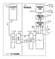
図5は、主基板31における演出制御コマンド送出部分と総合演出制御基板90における演出制御コマンド受信部分および制御コマンド送出部分の一例を示すブロック図である。図5に示された例では、主基板31のCPU56は、出力ポート571および出力バッファ回路63を介して遊技演出を指示するための演出制御コマンドデータを総合演出制御基板90に送出する。なお、図4に示されたように、主基板31のCPU56は、演出制御コマンドとは別に、賞球制御基板37に対して賞球個数を指示するための賞球制御コマンドを送出する。
【0041】
総合演出制御基板90において、主基板31からの演出制御コマンドは、入力バッファ88および入力ポート98を介して演出制御用CPU89(総合演出制御手段)に入力される。入力バッファ88は、信号を主基板31の側から総合演出制御基板90の側にしか伝えない不可逆性信号伝達手段である。従って、総合演出制御基板90側から主基板31側に信号が伝わる余地はなく、総合演出制御基板90内の回路に不正改造が加えられても、不正改造によって出力される信号が主基板31側に伝わることはない。また、主基板31と総合演出制御基板90との間の配線に不正基板等が接続されても、片方向にしか信号を伝えない出力バッファ回路63によって不正基板等からの不正信号が主基板31側に伝わることはない。
【0042】
演出制御コマンドは、主基板31のCPU56が実行する遊技進行に応じて送出される。演出制御用CPU89は、受信した演出制御コマンドにもとづいて、表示制御基板80に対して送出する表示制御コマンドおよびランプ制御基板35に対して送出するランプ制御コマンドを作成する。
【0043】
表示制御コマンドは、演出制御用CPU89から出力ポート91(出力ポートA)および出力バッファ回路94を介して送出される。また、ランプ制御コマンドは、演出制御用CPU89から出力ポート93(出力ポートC)および出力バッファ回路96を介して送出される。
【0044】
なお、後述するように、各制御コマンドは、制御データと制御データの出力を示すINT信号とを含む。また、この実施の形態では、各基板80,35に送出される制御コマンドは全く同じものである。
【0045】
図6は、表示制御基板80内の回路構成を、可変表示部9の一実現例であるCRT82および総合演出制御基板90の出力バッファ94とともに示すブロック図である。表示制御用CPU101は、制御データROM102に格納されたプログラムに従って動作し、総合演出制御基板90から入力バッファ回路105における入力バッファ105aを介してストローブ信号(INT信号)が入力されると、入力バッファ105aを介して表示制御コマンドを受信する。なお、総合演出制御基板90の出力バッファ94は、片方向(総合演出制御基板90から表示制御基板80に向かう方向)にしか信号を伝えない。
【0046】
この実施の形態では、特別遊技装置として可変表示部9を例示するので、特別遊技制御手段は、表示制御用CPU101等で実現される。以下、可変表示部9を制御する特別遊技制御手段を表示制御手段と呼ぶ。
【0047】
そして、表示制御用CPU101は、総合演出制御基板90から受信した表示制御コマンドに従って、CRT82に表示される画面の表示制御を行う。具体的には、表示制御コマンドに応じた指令をVDP103に与える。VDP103は、キャラクタROM86から必要なデータを読み出す。VDP103は、入力したデータに従ってCRT82に表示するための画像データを生成し、その画像データをVRAM87に格納する。そして、VRAM87内の画像データは、R,G,B信号に変換され、D−A変換回路104でアナログ信号に変換されてCRT82に出力される。
【0048】
なお、図6には、VDP103をリセットするためのリセット回路83、VDP103に動作クロックを与えるための発振回路85、および使用頻度の高い画像データを格納するキャラクタROM86も示されている。キャラクタROM86に格納される使用頻度の高い画像データとは、例えば、CRT82に表示される人物、動物、または、文字、図形もしくは記号等からなる画像などである。
【0049】
入力バッファ回路105における入力バッファ105aは、総合演出制御基板90から表示制御基板80へ向かう方向にのみ信号を通過させることができる。従って、表示制御基板80側から総合演出制御基板90側に信号が伝わる余地はない。なお、入力バッファ回路105の入力側にノイズフィルタを設けてもよい。
【0050】
図7は、表示制御用基板80と音制御基板70とが接続される形態を示すブロック図である。この実施の形態では、可変表示部9の表示等に対応した音発生を指示する音制御コマンドが、表示制御基板80から音制御基板70に送出される。
【0051】
図7に示すように、音制御コマンドは、表示制御基板80におけるI/Oポート部108から出力される。音制御基板70において、表示制御基板80からの各信号は、入力バッファ回路705を介して音制御用CPU701(音制御手段)に入力する。なお、音制御用CPU701がI/Oポートを内蔵していない場合には、入力バッファ回路705と音制御用CPU701との間に、I/Oポートが設けられる。そして、例えばディジタルシグナルプロセッサによる音声合成回路702は、音制御用CPU701の指示に応じた音声や効果音を発生し音量切替回路703に出力する。音量切替回路703は、音制御用CPU701の出力レベルを、設定されている音量に応じたレベルにして音量増幅回路704に出力する。音量増幅回路704は、増幅した音声信号をスピーカ27に出力する。
【0052】
入力バッファ回路705として、高周波信号を遮断するノイズフィルタ、例えば3端子コンデンサやフェライトビーズが使用されている。ノイズフィルタの存在によって、制御コマンドに基板間でノイズが乗ったとしても、その影響は除去される。また、表示制御基板80において、出力ポート108の外側に出力バッファ回路109が設けられている。出力バッファ回路109として、例えば、汎用のCMOS−ICである74HC244が用いられる。イネーブル端子には常にローレベル(GNDレベル)が与えられている。
【0053】
入力バッファ回路705は、表示制御基板80から音制御基板70へ向かう方向にのみ信号を通過させることができる。また、高周波信号を遮断するノイズフィルタ706として、例えば3端子コンデンサやフェライトビーズが使用されるが、ノイズフィルタ706の存在によって、制御コマンドに基板間でノイズが乗ったとしても、その影響は除去される。
【0054】
図8は、ランプ制御基板35の構成例を示すブロック図である。この実施の形態では、遊技領域7の外側に設けられている遊技効果LED28aおよび遊技効果ランプ28b,28c(枠ランプ)の点灯/消灯と、賞球ランプ51および球切れランプ52の点灯/消灯パターンと、始動入賞記憶個数と、ゲート通過記憶個数とを示すランプ制御コマンドが出力される。
【0055】
図8に示すように、ランプ制御に関する制御コマンドは、ノイズフィルタ356および入力バッファ回路355を介してランプ制御用CPU351(ランプ制御手段)に入力する。なお、ランプ制御用CPU351がI/Oポートを内蔵していない場合には、入力バッファ回路355とランプ制御用CPU351との間に、I/Oポートが設けられる。
【0056】
ランプ制御基板35において、ランプ制御用CPU351は、総合演出制御基板90からの各ランプ制御コマンドに応じて定義されている遊技効果LED28aおよび遊技効果ランプ28b,28cの点灯/消灯パターンに従って、遊技効果LED28aおよび遊技効果ランプ28b,28cに対して点灯/消灯信号を出力する。点灯/消灯信号は、遊技効果LED28aおよび遊技効果ランプ28b,28cに出力される。なお、点灯/消灯パターンは、ランプ制御用CPU351の内蔵ROMまたは外付けROMに記憶されている。
【0057】
また、主基板31のCPU56は、賞球時に賞球ランプ点灯を指示する制御コマンドを出力し、遊技盤裏面の遊技球補給路に設置されている球切れ検出センサがオンすると球切れランプ点灯を指示する演出制御コマンドを出力する。総合演出制御基板90の演出制御用CPU89は、演出制御コマンドに応じたランプ制御コマンドを作成しランプ制御基板35に出力する。ランプ制御基板35のランプ制御用CPU351は、ランプ制御コマンドに応じて、賞球ランプ51および球切れランプ52を点灯/消灯する。さらに、ランプ制御用CPU351は、始動入賞記憶個数を示すランプ制御コマンドに応じて始動入賞記憶表示器18の点灯個数を増減し、ゲート通過記憶個数を示すランプ制御コマンドに応じて通過記憶表示器41の点灯個数を増減する。
【0058】
入力バッファ回路355は、総合演出制御基板90からランプ制御基板35へ向かう方向にのみ信号を通過させることができる。また、高周波信号を遮断するノイズフィルタ356として、例えば3端子コンデンサやフェライトビーズが使用されるが、ノイズフィルタ356の存在によって、制御コマンドに基板間でノイズが乗ったとしても、その影響は除去される。
【0059】
図5〜図8に示されたように、この実施の形態では、主基板31のCPU56は、演出制御コマンドを総合演出制御基板90に送出する。総合演出制御基板90の演出制御用CPU89は、受信した演出制御コマンドに応じた表示制御コマンドおよびランプ制御コマンドを作成し表示制御基板80およびランプ制御基板35に送出する。表示制御基板80の表示制御用CPU101は、受信した表示制御コマンドに従って可変表示部9の表示制御を行うとともに、受信した表示制御コマンドに応じた音制御コマンドを作成して音制御基板70に送出する。
【0060】
音制御コマンドは、音発生パターンの切替タイミング等を示す情報となる。音制御手段の音発生パターン切替タイミングと表示制御手段の表示制御切替タイミングとは関連があるので、この実施の形態のように、表示制御手段が音制御コマンドを作成することによって表示制御状態と音発生制御状態との同期をとることが容易になる。
【0061】
図9は、主基板31から総合演出制御基板90に送出される遊技制御に関する演出制御コマンド、演出制御コマンドの送出条件(遊技状態)、および制御コマンド受信時の制御の概略を示す説明図である。ただし、図9に示されたコマンド種類は主基板31から送出される演出制御コマンドの種類を示しているが、表示制御基板80、ランプ制御基板35、音制御基板70における制御状態は、それぞれ、表示制御コマンド、ランプ制御コマンド、音制御コマンドに応じた制御状態である。
【0062】
例えば、遊技機の電源投入時には、主基板31のCPU56は、デモ(デモンストレーション)画面コマンドを総合演出制御基板90に送出する。すると、総合演出制御基板90から、表示制御基板80およびランプ制御基板35にデモ画面コマンド(演出制御コマンド)に対応した表示制御コマンドおよびランプ制御コマンドが送出される。表示制御基板80の表示制御用CPU101は、デモ画面コマンド(表示制御コマンド)を受信すると、可変表示部9にデモンストレーション画面を表示する制御を行うとともに、音制御コマンドを作成して音制御基板70に送出する。ランプ制御基板35におけるランプ制御用CPU351は、デモ画面コマンド(ランプ制御コマンド)を受信すると、遊技効果LED28aおよび遊技効果ランプ29b,28cを、デモンストレーション時の点灯パターンとしてあらかじめ決まられているパターンで点灯制御する。
【0063】
なお、図9において、「なし」は、その制御コマンドに対応する制御がないことを示す。従って、各制御基板におけるCPUは、「なし」に対応する制御コマンドを受信しても、それを無視する。また、「変化なし」は、そのコマンドを受信しても制御状態を変化させないことを示す。従って、表示制御用CPU101は、「なし」となっているデモ画面コマンド(音制御コマンド)等を音制御基板70に供給しなくてもよい。
【0064】
また、この実施の形態では、ランプ制御手段は、複数種類のランプ制御コマンドに対して同一の発光パターンで発光制御することが可能である。例えば、ラウンド開始コマンドには大当り遊技中のラウンド数を示す情報が含まれているので、遊技の進行に伴って、各ラウンドの開始時に送出されるラウンド開始コマンドは、それぞれ、実質的に異なるコマンドとなっている。しかし、いずれのラウンド開始コマンドを受信しても、ランプ制御手段は、1つの点灯パターン(ラウンド中点灯パターン)で点灯制御を行う。
【0065】
さらに、ラウンド開始コマンド、大入賞口入賞コマンドおよびV入賞コマンドは、大当り遊技中に可変表示部9の表示状態を変化させるために遊技制御手段から総合演出制御手段を介して送出されるコマンドであるが、それらのコマンドを受信したランプ制御手段は、点灯パターンを変化させない。すなわち、大当り遊技中では、ランプ制御手段は、受信したコマンドに応じた制御を行わず、以前に受信したコマンドにもとづく制御を行う。ただし、ラウンド開始コマンドについては、2ラウンド目以降のラウンド開始コマンドを受信すると、点灯パターンを変化させない制御を行う。
【0066】
同様に、大当り遊技中では、音制御手段は、ラウンド開始コマンド、大入賞口入賞コマンドおよびV入賞コマンドを表示制御基板80から受信しても、音発生パターンを変化させない。すなわち、受信したコマンドに応じた制御を行わず、以前に受信したコマンドにもとづく制御を行う。なお、表示制御基板80の表示制御用CPU101は、それらの音制御コマンドを出力しないように構成されていてもよい。この実施の形態では、それらのコマンドは音発生制御に影響を与えないからである。
【0067】
図10(A)は、図9に示された制御コマンド(演出制御コマンド)のコード割り当ての一例を示す説明図である。この実施の形態では、主基板31から総合演出制御基板90に送出される各演出制御コマンドは2バイト構成であるが、演出制御コマンドの長さは2バイト以外であってもよい。
【0068】
1バイト目が80Hである演出制御コマンドは変動開始を示すコマンドであるが、その2バイト目は、可変表示部9における図柄の変動時間を特定可能な情報を示す。図10(B)に示すように、この例では、変動時間を特定可能な情報として、はずれ変動期間、確変時に行われる変動の変動期間、短期間のリーチ変動の変動期間、中期間のリーチ変動の変動期間および長期間のリーチ変動の変動期間がある。主基板31のCPU56は、可変表示部9における図柄の変動を開始させるときに図柄の変動時間を特定可能な情報を演出制御コマンドとして総合演出制御基板90に対して送出するのであるが、その際に、左右中確定図柄を示す演出制御コマンドも送出する。1バイト目が81Hであって2バイト目が00Hである演出制御コマンドは、可変表示部9における図柄の確定を指定する確定コマンドである。主基板31のCPU56は、変動開始の演出制御コマンドで指定した変動時間が経過すると、総合演出制御基板90に対して確定コマンドを送出する。
【0069】
次に遊技機の動作について説明する。
図11は、主基板31におけるCPU56の動作を示すフローチャートである。CPU56は、ROM54に格納されている遊技制御プログラムに従って遊技制御を行う。図11に示された処理は、定期リセット回路66が発するリセットパルスによって、例えば2ms毎に起動される。
【0070】
CPU56が起動されると、CPU56は、まず、クロックモニタ制御を動作可能状態にするために、内蔵されているクロックモニタレジスタをクロックモニタイネーブル状態に設定する(ステップS1)。なお、クロックモニタ制御とは、入力されるクロック信号の低下または停止を検出すると、CPU56の内部で自動的にリセットを発生する制御である。
【0071】
次いで、CPU56は、スタックポインタの指定アドレスをセットするためのスタックセット処理を行う(ステップS2)。この例では、スタックポインタに00FFHが設定される。そして、システムチェック処理を行う(ステップS3)。システムチェック処理では、CPU56は、RAM55にエラーが含まれているか判定し、エラーが含まれている場合には、RAM55を初期化するなどの処理を行う。
【0072】
なお、電源投入時であれば、例えばステップS3において、総合演出制御基板90に対してデモ画面コマンドを送出する制御を行う。具体的には、デモ画面コマンドの送出要求をセットする。
【0073】
次に、制御コマンドの送出要求がセットされていれば、総合演出制御基板90に送出される演出制御コマンドをRAM55の所定の領域に設定する処理を行った後に(制御データ設定処理:ステップS4)、演出制御コマンドを出力する処理の一部を実行する(制御データ出力処理A:ステップS5A)。制御データ出力処理Aの処理内容については、後で詳述する。
【0074】
次いで、各種出力データの格納領域の内容を各出力ポートに出力する処理を行う(データ出力処理:ステップS6)。また、ホール管理用コンピュータに出力される大当り情報、始動情報、確率変動情報などの出力データを格納領域に設定する出力データ設定処理を行う(ステップS8)。さらに、パチンコ遊技機1の内部に備えられている自己診断機能によって種々の異常診断処理が行われ、その結果に応じて必要ならば警報が発せられる(エラー処理:ステップS9)。
【0075】
次に、遊技制御に用いられる大当り決定用の乱数等の各判定用乱数を示す各カウンタを更新する処理を行う(ステップS10)。図12は、各乱数を示す説明図である。各乱数は、以下のように使用される。
(1)ランダム1:大当りを発生させるか否か決定する(大当り決定用=特別図柄決定用)
(2)ランダム2−1〜2−3:左右中のはずれ図柄決定用
(3)ランダム3:大当り時の図柄の組合せを決定する(大当り図柄決定用=特別図柄判定用)
(4)ランダム4:はずれ時にリーチするか否か決定する(リーチ判定用)
(5)ランダム5:リーチ期間を決定する(リーチ期間決定用)
【0076】
なお、遊技効果を高めるために、上記(1)〜(5)の乱数以外の乱数も用いられている。
ステップS10では、CPU56は、(1)の大当り決定用乱数および(3)の大当り図柄判定用乱数を生成するためのカウンタのカウントアップ(1加算)を行う。すなわち、それらが判定用乱数である。
【0077】
次に、CPU56は、特別図柄プロセス処理を行う(ステップS11)。特別図柄プロセス制御では、遊技状態に応じてパチンコ遊技機1を所定の順序で制御するための特別図柄プロセスフラグに従って該当する処理が選び出されて実行される。そして、特別図柄プロセスフラグの値は、遊技状態に応じて各処理中に更新される。
【0078】
ここで、制御コマンドを出力する処理の一部を実行する(制御データ出力処理B:ステップS5B)。制御データ出力処理Bの処理内容については、後で詳述する。
【0079】
また、普通図柄プロセス処理を行う(ステップS12)。普通図柄プロセス処理では、7セグメントLEDによる可変表示器10を所定の順序で制御するための普通図柄プロセスフラグに従って該当する処理が選び出されて実行される。そして、普通図柄プロセスフラグの値は、遊技状態に応じて各処理中に更新される。
【0080】
さらに、CPU56は、スイッチ回路58を介して、ゲートセンサ12、始動口センサ17およびカウントセンサ23の状態を入力し、各入賞口や入賞装置に対する入賞があったか否か判定する(スイッチ処理:ステップS13)。
【0081】
CPU56は、さらに、表示用乱数を更新する処理を行う(ステップS15)。すなわち、ランダム2,4,5を生成するためのカウンタのカウントアップ(1加算)を行う。
【0082】
また、CPU56は、賞球制御基板37との間の信号処理を行う(ステップS16)。すなわち、所定の条件が成立すると賞球制御基板37に賞球制御コマンドを出力する。賞球制御基板37に搭載されている賞球制御用CPUは、賞球制御コマンドに応じて玉払出装置97を駆動する。
【0083】
ここで、制御コマンドを出力する処理の一部を実行する(制御データ出力処理B:ステップS5C)。制御データ出力処理Cの処理内容については、後で詳述する。
その後、CPU56は、次に定期リセット回路66からリセットパルスが与えられるまで、ステップS17の表示用乱数更新処理を繰り返す。
【0084】
この実施の形態では、CPU56は、定期リセット回路66から定期的に発生される定期リセット信号に応じてメイン処理が実行されるが、定期リセット回路66が存在しない構成として、CPU56の内部で定期的にタイマ割込を発生させ、タイマ割込処理によってメイン処理を実行するように構成してもよい。
【0085】
次に、始動入賞口14への入賞にもとづいて可変表示部9に可変表示される図柄の決定方法について図13〜図15のフローチャートを参照して説明する。図13は打球が始動入賞口14に入賞したことを判定する処理を示し、図14は可変表示部9の可変表示の停止図柄を決定する処理を示す。図15は、大当りとするか否か決定する処理を示すフローチャートである。
【0086】
打球が遊技盤6に設けられている始動入賞口14に入賞すると、始動口センサ17がオンする。ステップS10のスイッチ処理において、CPU56は、スイッチ回路58を介して始動口センサ17がオンしたことを判定すると(ステップS41)、始動入賞記憶数が最大値である4に達しているかどうか確認する(ステップS42)。始動入賞記憶数が4に達していなければ、始動入賞記憶数を1増やし(ステップS43)、大当り決定用乱数の値を抽出する。そして、それを始動入賞記憶数の値に対応した乱数値格納エリアに格納する(ステップS44)。そして、特図始動入賞コマンド(演出制御コマンド)の送出要求をセットする(ステップS45)なお、始動入賞記憶数が4に達している場合には、始動入賞記憶数を増やす処理を行わない。すなわち、この実施の形態では、最大4個の始動入賞口17に入賞した打球数が記憶可能である。
【0087】
CPU56は、ステップS11の特別図柄プロセス処理において始動入賞記憶数の値を確認する(ステップS50)。始動入賞記憶数が0でなければ、始動入賞記憶数=1に対応する乱数値格納エリアに格納されている値を読み出すとともに(ステップS51)、始動入賞記憶数の値を1減らし、かつ、各乱数値格納エリアの値をシフトする(ステップS52)。すなわち、始動入賞記憶数=n(n=2,3,4)に対応する乱数値格納エリアに格納されている値を、始動入賞記憶数=n−1に対応する乱数値格納エリアに格納する。
【0088】
そして、CPU56は、ステップS51で読み出した値、すなわち抽出されている大当り決定用乱数の値にもとづいて当たり/はずれを決定する(ステップS53)。ここでは、大当り決定用乱数は0〜249の範囲の値をとることにする。図15に示すように、低確率時には例えばその値が「3」である場合に「大当り」と決定し、それ以外の値である場合には「はずれ」と決定する。高確率時には例えばその値が「3」,「7」,「79」,「103」,「107」のいずれかである場合に「大当り」と決定し、それ以外の値である場合には「はずれ」と決定する。
【0089】
大当りと判定されたときには、大当り図柄決定用乱数(ランダム3)を抽出しその値にもとづいて大当り図柄を決定する(ステップS62)。そして、大当り図柄が、高確率状態を生じさせるための確変図柄であれば(ステップS64)、確変フラグをセットする(ステップS65)。また、リーチ期間決定用乱数(ランダム5)を抽出しその値にもとづいてリーチ期間を決定する(ステップS57)。
【0090】
はずれと判定された場合には、CPU56は、リーチとするか否か判定する(ステップS58)。例えば、リーチ判定用の乱数であるランダム4の値が「105」〜「1530」のいずれかである場合には、リーチとしないと決定する。そして、リーチ判定用乱数の値が「0」〜「104」のいずれかである場合にはリーチとすることを決定する。リーチとすることを決定したときには、CPU56は、リーチ図柄の決定を行う。
【0091】
この実施の形態では、ランダム2−1の値に従って左右図柄を決定する(ステップS59)。また、ランダム2−2の値に従って中図柄を決定する(ステップS60)。すなわち、ランダム2−1およびランダム2−2の値の0〜15の値に対応したいずれかの図柄が停止図柄として決定される。ここで、決定された中図柄が左右図柄と一致した場合には、中図柄に対応した乱数の値に1加算した値に対応する図柄を中図柄の確定図柄として、大当り図柄と一致しないようにする。さらに、CPU56は、また、リーチ期間決定用乱数(ランダム5)を抽出しその値にもとづいてリーチ期間を決定する(ステップS57)。
【0092】
ステップS58において、リーチしないことに決定された場合には、ランダム2−1〜2−3の値に応じて左右中図柄を決定する(ステップS61)。
以上のようにして、始動入賞にもとづく図柄変動の表示態様が大当りとするか、リーチ態様とするか、はずれとするか決定され、それぞれの停止図柄の組合せが決定される。
【0093】
なお、高確率状態において、次に大当りとなる確率が上昇するとともに、7セグメントLEDによる可変表示器10の可変表示の確定までの時間が短縮され、かつ、可変表示器10の可変表示結果にもとづく当たり時の可変入賞球装置15の開放回数および開放時間が高められるようにパチンコ遊技機1が構成されていてもよいし、可変表示器10の可変表示結果にもとづく当たりの確率が高くなるように構成されていてもよい。また、それらのうちのいずれか一つまたは複数の状態のみが生ずるパチンコ遊技機1においても本発明は適用可能である。
【0094】
例えば、可変表示部9の停止図柄の組合せが特定図柄となった場合に、大当りとなる確率は上昇しないが可変表示器10の可変表示結果にもとづく当たり時の可変入賞球装置15の開放回数および開放時間が高められる遊技機においても、リーチとすることが決定されたら、左右の停止図柄を特定図柄の表示態様と一致させるか否か、すなわちどの図柄でリーチ状態を発生させるかが所定の乱数等の手段によって決定される遊技機においても本発明を適用可能である。
また、この実施の形態で用いられた乱数および乱数値の範囲は一例であって、どのような乱数を用いてもよいし、範囲設定も任意である。
【0095】
上述したように、始動入賞口14に打球が入賞すると、CPU56は、ステップS11(図11参照)の特別図柄プロセス処理において、大当りとするかはずれとするかと、停止図柄とを決定するが、その決定に応じた演出制御コマンドを総合演出制御基板90に与える。
【0096】
図16はCPU56が実行する特別図柄プロセス処理のプログラムの一例を示すフローチャートである。図16に示す特別図柄プロセス処理は、図11のフローチャートにおけるステップS11の具体的な処理である。基本回路53のCPU56は、特別図柄プロセス処理を行う際に、その内部状態に応じて、図16に示すステップS300〜S309のうちのいずれかの処理を行う。各処理において、以下のような処理が実行される。
【0097】
特別図柄変動待ち処理(ステップS300):始動入賞口14(この実施の形態では可変入賞球装置15の入賞口)に打球入賞して始動口センサ17がオンするのを待つ。始動口センサ17がオンすると、始動入賞記憶数が満タンでなければ、始動入賞記憶数が+1される。そして、大当り判定用乱数を抽出する。
【0098】
特別図柄判定処理(ステップS301):特別図柄の可変表示が開始できる状態になると、始動入賞記憶数を確認する。始動入賞記憶数が0でなければ、抽出されている大当り決定用乱数の値に応じて大当りとするかはずれとするか決定する。すなわち、図14に示された処理の前半が実行される。
【0099】
停止図柄設定処理(ステップS302):左右中図柄の停止図柄を決定する。すなわち、図14に示された処理の中半が実行される。
【0100】
リーチ動作設定処理(ステップS303):リーチ判定用乱数の値に応じてリーチ動作するか否か決定するとともに、リーチ期間決定用乱数の値に応じてリーチ動作の変動時間を決定する。すなわち、図14に示された処理の後半が実行される。ただし、ここで決定されるリーチ期間は、変動時間のみを示す大まかなものである。
【0101】
全図柄変動開始処理(ステップS304):可変表示部9において全図柄が変動開始されるように制御する。このとき、総合演出制御基板90に対して、左右中最終停止図柄を指令する演出制御コマンド(コマンド90H,XXH、91H,XXHおよび92H,XXH)と変動態様を指令する演出制御コマンド(コマンド80H,XXH)とが送信される。なお、「X」は任意の数であることを示す。総合演出制御基板90の演出制御用CPU89は、受信した演出制御コマンドに応じた表示制御コマンドおよびランプ制御コマンドを、表示制御基板80およびランプ制御基板35に送出する。また、表示制御基板80の表示制御用CPU101は、受信した表示制御コマンドに応じた音制御コマンドを音制御基板70に送出する。なお、左右中最終停止図柄を指令するコマンドは音発生制御に影響しないので、表示制御用CPU101は、それらのコマンドについては音制御基板70に送出しなくてもよい。
【0102】
全図柄停止待ち処理(ステップS305):所定時間が経過すると、可変表示部9において表示される全図柄が停止されるように制御する。また、全図柄停止のタイミングまで、所定のタイミングで左右図柄が停止されるように制御する。すなわち、総合演出制御基板90に、確定コマンド(81H,00H)が送出される。総合演出制御基板90の演出制御用CPU89は、受信した確定コマンド(演出制御コマンド)に応じた表示制御コマンドおよびランプ制御コマンドを、表示制御基板80およびランプ制御基板35に送出する。また、表示制御基板80の表示制御用CPU101は、受信した表示制御コマンドに応じた音制御コマンドを音制御基板70に送出する。
【0103】
大当り表示処理(ステップS306):停止図柄が大当り図柄の組み合わせである場合には、大当り発生の制御コマンド(81H,01H)が総合演出制御基板90に送出されるように制御するとともに内部状態(プロセスフラグ)をステップS307に移行するように更新する。そうでない場合には、内部状態をステップS309に移行するように更新する。なお、大当り図柄の組み合わせは、左右中図柄が揃った組み合わせである。総合演出制御基板90の演出制御用CPU89は、受信した大当り発生の制御コマンド(演出制御コマンド)に応じた表示制御コマンドおよびランプ制御コマンドを、表示制御基板80およびランプ制御基板35に送出する。また、表示制御基板80の表示制御用CPU101は、受信した表示制御コマンドに応じた音制御コマンドを音制御基板70に送出する。
【0104】
大入賞口開放開始処理(ステップS307):大入賞口を開放する制御を開始する。具体的には、カウンタやフラグを初期化するとともに、ソレノイド21を駆動して大入賞口を開放する。また、ラウンド開始の制御コマンド(82H,XXH)を、総合演出制御基板90に送出する制御を行う。総合演出制御基板90の演出制御用CPU89は、受信したラウンド開始の制御コマンド(演出制御コマンド)に応じた表示制御コマンドおよびランプ制御コマンドを、表示制御基板80およびランプ制御基板35に送出する。また、表示制御基板80の表示制御用CPU101は、受信した表示制御コマンドに応じた音制御コマンドを音制御基板70に送出する。
【0105】
大入賞口開放中処理(ステップS308):ラウンド終了条件(例えば大入賞口への入賞球数が所定個に達した)が成立したら、ラウンド終了の制御コマンド(81H,03H)を、総合演出制御基板90に送出する制御を行う。そして、大当り遊技の終了条件が成立していなければ、特別図柄プロセスフラグをステップS307に対応した値にする。大当り遊技の終了条件が成立していれば、特別図柄プロセスフラグをステップS309に対応した値にする。なお、ラウンド終了条件が成立するまでに、Vカウントスイッチ22によってVゾーンへの入賞が検出されたら、V入賞の制御コマンド(81H,02H)を、総合演出制御基板90に送出する制御を行う。総合演出制御基板90の演出制御用CPU89は、受信したラウンド終了の制御コマンドやV入賞の制御コマンド(演出制御コマンド)に応じた表示制御コマンドおよびランプ制御コマンドを、表示制御基板80およびランプ制御基板35に送出する。また、表示制御基板80の表示制御用CPU101は、受信した表示制御コマンドに応じた音制御コマンドを音制御基板70に送出する。なお、この実施の形態では、V入賞は音発生制御に影響を与えないので、表示制御用CPU101は、その音制御コマンドを音制御基板70に送出しなくてもよい。
【0106】
大当り終了処理(ステップS309):大当り終了の制御コマンド(81H,04H)を、総合演出制御基板90に送出する制御を行う。そして、確変フラグがセットされている場合には、確変開始の制御コマンド(B0H,01H)を、総合演出制御基板90に送出する制御を行う。また、高確率状態であって、その状態の終了条件(例えば、規定回変動が行われた)が成立していたら、確変終了の制御コマンド(B0H,02H)を、総合演出制御基板90に送出する制御を行う。その後、特別図柄プロセスフラグをステップS300に対応した値にする。総合演出制御基板90の演出制御用CPU89は、受信したそれらの演出制御コマンドに応じた表示制御コマンドおよびランプ制御コマンドを、表示制御基板80およびランプ制御基板35に送出する。また、表示制御基板80の表示制御用CPU101は、受信した表示制御コマンドに応じた音制御コマンドを音制御基板70に送出する。なお、この実施の形態では、確変開始および確変終了は音発生制御に影響を与えないので、表示制御用CPU101は、それらの音制御コマンドを音制御基板70に送出しなくてもよい。
【0107】
上記の各ステップの処理に応じて、遊技制御プログラム中の演出制御コマンドを送出する処理を行うモジュール(図11におけるステップS5A,5B,5C)は、対応する演出制御コマンドを出力ポート571に出力するとともに、ストローブ信号を対応する出力ポートに出力する。
【0108】
図柄変動制御に関して、主基板31のCPU56は、変動開始に関連した時期(この例では変動開始時)に変動時間を特定可能な情報(変動態様を特定可能な制御コマンド)と確定図柄を特定可能な情報とを送出するだけであり、具体的な図柄変動制御は演出制御用CPU89および表示制御用CPU101の制御によって実現される。また、主基板31のCPU56は、変動時間が経過したら、総合演出制御基板90に対して確定コマンドを送出する。総合演出制御基板90の演出制御用CPU89は、受信した確定コマンドに応じた表示制御コマンドおよびランプ制御コマンドを、表示制御基板80およびランプ制御基板35に送出する。また、表示制御基板80の表示制御用CPU101は、受信した表示制御コマンドに応じた音制御コマンドを音制御基板70に送出する。ただし、上述したように、表示制御用CPU101は、音発生制御に影響を与えないコマンド(図9において「なし」または「変化なし」とされているものに対応したコマンド)を音制御基板70に送出しなくてもよい。
【0109】
図17は、普通図柄プロセス処理(図11におけるステップS12)を示すフローチャートである。普通プロセス図柄処理では、CPU56は、ステップS61のゲートスイッチ処理を実行した後に、普通図柄プロセスフラグの値に応じてステップS62〜S65の処理のうちのいずれかの処理を実行する。
【0110】
ゲートスイッチ処理では、普通図柄変動開始の条件となる通過ゲート11の打球通過にもとづくゲートスイッチ12のオンを検出する。ゲートスイッチ12がオンしていたら、ゲート通過記憶カウンタが最大値(この例では「4」)に達しているか否か確認する。達していなければ、ゲート通過記憶カウンタの値を+1する。なお、ゲート通過記憶カウンタの値に応じてCPU56は、普図始動入賞の演出制御コマンド(A0H,XXH)の送出要求をセットする。そして、CPU56は、当り判定用乱数の値を抽出しその値を記憶する。
【0111】
ステップS62の普通図柄変動待ち処理では、CPU56は、普通図柄通過記憶カウンタの値が0以外であれば、普通図柄プロセスフラグの値を更新する。普通図柄通過記憶カウンタの値が0であれば何もしない。
【0112】
ステップS63の普通図柄判定処理では、CPU56は、ゲート通過記憶数=1に対応する乱数値格納エリアに格納されている値を読み出すとともに、ゲート通過記憶カウンタの値を1減らし、かつ、各乱数値格納エリアの値をシフトする。すなわち、ゲート通過記憶カウンタ=n(n=2,3,4)に対応する乱数値格納エリアに格納されている値を、ゲート通過記憶カウンタ=n−1に対応する乱数値格納エリアに格納する。
【0113】
そして、CPU56は、抽出されている当り判定用乱数の値にもとづいて当たり/はずれを決定する。当りと決定したときには、例えば普通図柄決定用乱数に値に応じて当り図柄を決定する。そして、普通図柄プロセスタイマをスタートする。また、普図変動開始の演出制御コマンド(A1H,XXH)の送出要求をセットする。さらに、普通図柄プロセスフラグをステップS64に対応した値に更新する。
【0114】
例えば、高確率時には、普通図柄プロセスタイマに5.1秒に相当する値を設定する。低確率時には、普通図柄プロセスタイマに29.2秒に相当する値を設定する。そして、普通図柄プロセスフラグの値を更新する。なお、普通図柄は、普通図柄プロセスタイマに設定された時間変動する。従って、可変表示器10において、普通図柄は、高確率時には5.1秒間変動し、低確率時には29.2秒間変動する。ステップS64の普通図柄変動処理では、CPU56は、普通図柄変動タイマがタイムアップする毎に(例えば100ms)、普通図柄表示カウンタを更新する。そして、更新後の普通図柄表示カウンタの値が可変表示器10に表示される。従って、この例では、100ms毎に普通図柄は変動する。
【0115】
普通図柄変動処理において、普通図柄プロセスタイマがタイムアップすると、CPU56は、普通図柄決定用乱数に値に応じて決定されている図柄を可変表示器10に停止表示する制御を行う。
【0116】
ステップS65の普通図柄停止処理では、CPU56は、当りと決定されているときには、普通電動役物バッファに可変入賞球装置15の開放パターンを設定する。そして、普通図柄プロセスフラグの値を、普通図柄変動待ちの状態に応じた値に更新する。
【0117】
開放パターンは、例えば、低確率時には、可変入賞球装置15が1回だけ0.2秒間開放するようなパターンである。また、高確率時には、可変入賞球装置15が1.15秒間開放した後4.4秒の閉成期間をおいて再度1.15秒間開放するようなパターンである。可変入賞球装置15は、開放パターンに従って開閉制御される。なお、この実施の形態では、可変入賞球装置15は、始動入賞口14と兼用されている。
【0118】
図18は、主基板31から総合演出制御基板90に送信される演出制御コマンドを示す説明図である。図22に示すように、この実施の形態では、演出制御コマンドは、制御データCD0〜CD7の8本のデータ線で主基板31から総合演出制御基板90に送信される。また、主基板31と総合演出制御基板90との間には、INT信号を送信するためのINT信号の信号線も配線されている。
【0119】
図19は、主基板31から総合演出制御基板90に与えられる制御コマンドの送出タイミングを示すタイミング図である。図19に示すように、この実施の形態では、定期リセット信号の発生間隔(2ms)において1つの演出制御コマンドが送出される。演出制御コマンドの各バイトが出力されてから800μs間INT信号がオン状態(ローレベル)になる。総合演出制御基板90の演出制御用CPU89は、INT信号がオンしたことを検出すると、演出制御コマンドを取り込む処理を行う。
【0120】
この実施の形態では、演出制御コマンドは2バイト構成であるから、1つの演出制御コマンドが出力される際に、2回INT信号が出力される。なお、演出制御コマンドは2バイト構成に限られず、情報量に応じて2バイト以上であってもよい。
【0121】
また、この実施の形態では、主基板31のCPU56は、所定の制御変化点において、1回だけ総合演出制御基板90が受信可能に演出制御コマンドを送出する。従って、遊技制御手段の制御コマンド送出に関する負荷が低減される。
【0122】
図20は、図11に示されたメイン処理における制御データ出力処理A(ステップS5A)を示すフローチャートである。制御データ出力処理Aにおいて、CPU56は、ポート出力要求がセットされているか否か判定する(ステップS421)。ポート出力要求がセットされている場合には、ポート出力要求をリセットし(ステップS422)、ポート格納領域の内容(演出制御コマンドの1バイト目)を出力ポート571に出力する(ステップS423)。
【0123】
そして、INT信号をローレベル(オン状態)にし(ステップS424)、800μsタイマをスタートさせて(ステップS425)、データ送出中フラグをオンする(ステップS426)。なお、ポート出力要求は、図11に示されたメイン処理における制御データ設定処理(ステップS4)でセットされる。
【0124】
図21は、図11に示されたメイン処理における制御データ出力処理B(ステップS5B)を示すフローチャートである。制御データ出力処理Bにおいて、CPU56は、まず、データ送出中フラグがオンしているか否か確認する(ステップS431)。オンしていれば、制御データ出力処理Aでセットされている800μsタイマがタイムアウトするのを待つ(ステップS432)。
【0125】
800μsタイマがタイムアウトしたら、INT信号をハイレベル(オフ状態)にし(ステップS433)、所定期間のディレイタイムをおいて(ステップS434)、ポート格納領域の内容(制御コマンドの2バイト目)を出力ポート571に出力する(ステップS435)。なお、ディレイタイムは、図19に示されたINT信号の出力タイミングにおける1回目のINT信号のオン期間と2回目のINT信号のオン期間との間のオフ期間を作成するための時間である。
【0126】
そして、INT信号をローレベル(オン状態)にし(ステップS424)、800μsタイマをスタートさせる(ステップS425)。
【0127】
図22は、図11に示されたメイン処理における制御データ出力処理C(ステップS5C)を示すフローチャートである。制御データ出力処理Cにおいて、CPU56は、まず、データ送出中フラグがオンしているか否か確認する(ステップS441)。オンしていれば、制御データ出力処理Bでセットされている800μsタイマがタイムアウトするのを待つ(ステップS442)。
【0128】
800μsタイマがタイムアウトしたら、INT信号をハイレベル(オフ状態)にし(ステップS443)、データ送出中フラグをオフする(ステップS444)。
以上のようにして、図19に示されたようなタイミングで、演出制御コマンドが主基板31から総合演出制御基板90に送出される。
【0129】
なお、図11に示されたように、メイン処理の随所で制御データ出力処理A,B,Cを実行する方法は一例であって、他の方法を用いてもよい。例えば、タイマ割り込みによってINT信号のオン/オフ制御を行ってもよい。いずれにせよ、図19に示されたようなタイミングで同一の制御コマンドが主基板31から総合演出制御基板90に送出されればよい。なお、INT信号のオン期間である800μsも一例であって、機種に応じて任意に設定することができる。
【0130】
次に、図柄の変動の一例を説明する。
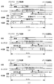
図23は、この実施の形態で用いられる各変動態様を構成するパターン(変動状態)を示す説明図である。図24は、リーチとしないはずれ時の図柄の変動の一例を示すタイミング図である。また、図25〜図28は、リーチ時(大当りの場合および大当りとしない場合)の図柄の変動の一例を示すタイミング図である。図24〜図28に示す図柄の変動等は、総合演出制御基板90から送出された表示制御コマンドを受信した表示制御用CPU101によって実現される。
【0131】
この実施の形態では、はずれ時には、図24(A)に示すように、可変表示部9における「左」の図柄表示エリアにおいて、まず、パターンaに従って図柄の変動が行われる。パターンaは、図23に示すように、少しずつ変動速度が上がるパターンである。その後、パターンbの一定速の変動が行われ、停止図柄の3図柄前の図柄が表示されるように制御された後、パターンc従って3図柄の変動が行われる。パターンcは、図23に示すように、徐々に遅くなって停止するパターンである。なお、図24に示すコマンドA0は、変動の開始から確定までの変動態様(はずれの態様)を指示するものである。
【0132】
また、可変表示部9における「右」の図柄表示エリアにおいて、パターンaに従って図柄の変動が行われる。その後、一定速変動の後、停止図柄の3図柄前の図柄が表示されるように制御された後、パターンcに従って図柄の変動が行われる。「中」の図柄表示エリアにおいても、まず、パターンaに従って図柄の変動が行われる。その後、一定速変動の後、停止図柄の3図柄前の図柄が表示されるように制御された後、パターンcに従って図柄の変動が行われる。
【0133】
なお、表示制御基板80の表示制御用CPU101は、中図柄が確定するまで、左右図柄を変動方向の正方向と逆方向に繰り返し変動させる。すなわち、左右図柄を、いわゆる揺れ変動状態に表示制御する。揺れ変動とは、図柄が上下に揺れる表示されることをいう。また、揺れ変動は、最終停止図柄(確定図柄)が表示されるまで行われる。そして、総合演出制御基板90から全図柄停止を指示する表示制御コマンドを受信すると、左右図柄の揺れ変動状態を終了させて左右中図柄が動かない確定状態になる。なお、中図柄も、パターンcによる変動の後に揺れ動作を行い、その後確定状態になるようにしてもよい。また、揺れ変動を、図柄を上下に揺らす態様ではなく、左右に揺らしたりする態様としてもよい。
【0134】
図柄が変動している間、表示制御用CPU101は、背景として「道場」が表示されるように表示制御を行うとともに、画面中にキャラクタAを表示して適宜キャラクタAを運動させるように表示制御を行う。具体的には、背景およびキャラクタをVDP103に通知する。すると、VDP103は、指示された背景の画像データを作成する。また、指示されたキャラクタの画像データを作成し背景画像と合成する。さらに、VDP103は、合成画像に、左右中図柄の画像データを合成する。VDP103は、キャラクタが運動するような表示制御および図柄が変動するような表示制御も行う。すなわち、あらかじめ決められている運動パターンに従ってキャラクタの形状および表示位置を変える。また、表示制御用CPU101から通知される変動速度に応じて図柄表示位置を変えていく。
【0135】
なお、表示制御用CPU101は、左右中の図柄表示エリアにおいて、指定された停止図柄で図柄変動が停止するように、所定のタイミングで停止図柄の3図柄前の図柄を表示制御する。変動開始時に左右中の停止図柄が通知され、かつ、はずれ時の変動態様はあらかじめ決められているので、表示制御用CPU101は、パターンaからパターンbへの切替タイミングおよびパターンbからパターンcへの切替タイミングを認識することができるとともに、差し替えるべき3図柄前の図柄も決定できる。決定された差し替え図柄はVDP103に通知され、VDP103は、そのときに表示している図柄に関係なく、通知された図柄を表示する。
【0136】
図24(B)は、確率変動状態におけるはずれ時の変動態様の一例を示す。この変動態様では、図に示されるように、パターンa、パターンbおよびパターンcに従って左右中図柄の変動が行われた後に、左右中図柄が同時に停止する。この変動態様を用いるときも、表示制御用CPU101は、背景として「道場」が表示されるように表示制御を行うとともに、画面中にキャラクタAを表示して適宜キャラクタAを運動させるように表示制御を行うことにする。
【0137】
つまり、この実施の形態では、表示制御用CPU101は、総合演出制御基板90から「はずれ」であることを指定する表示制御コマンドを受信すると、キャラクタAを出現させること、および「道場」の背景画面を使用することを決定する。
【0138】
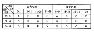
図25は、総合演出制御基板90から変動時間として19.5秒(リーチ短期間)が通知されたときに表示される変動態様の例を示す。図25には、複数の変動態様として(A)〜(C)の3パターンが例示されている。
【0139】
図25(A)に示された変動態様では、左右図柄が停止した後パターンdの中図柄の変動が行われる。なお、表示制御用CPU101は、中図柄変動中の左右図柄の停止状態では左右図柄を揺れ動作させている。パターンdは、変動速度が徐々に低下し、その後一定速度で変動が行われるパターンである。そして、リーチ動作に入り、パターンbおよびパターンcに従って中図柄の変動が行われる。総合演出制御基板90から全図柄停止を指示する表示制御コマンドを受信すると、左右図柄の揺れ変動状態を終了させて左右中図柄が動かない確定状態になる。
【0140】
また、表示制御用CPU101は、総合演出制御基板90から通知されている停止図柄で図柄が確定するように、リーチ動作開始前に図柄の差し替え(図柄の飛ばし制御)を行う。変動態様はあらかじめ決められているので、表示制御用CPU101は、パターンdからパターンbへの切替タイミングおよびパターンbからパターンcへの切替タイミングを認識することができるとともに、差し替えるべき3図柄前の図柄も決定できる。なお、中図柄の変動中に、背景およびキャラクタの種類は変化しない。
【0141】
図25(B)に示された変動態様では、左右図柄が停止した後パターンdの中図柄の変動が行われる。そして、リーチ動作に入り、パターンaおよびパターンcに従って中図柄の変動が行われる。総合演出制御基板90から全図柄停止を指示する表示制御コマンドを受信すると、左右図柄の揺れ変動状態を終了させて左右中図柄が動かない確定状態になる。また、表示制御用CPU101は、総合演出制御基板90から通知されている停止図柄で図柄が確定するように、リーチ動作開始前に図柄の差し替えを行う。なお、図25(B)に示された変動態様では右図柄停止時に、表示制御用CPU101は、キャラクタAが右図柄を蹴るように表示制御を行う。従って、遊技者は、あたかも、キャラクタAが右図柄を蹴ることによってリーチが成立したように感ずる。
【0142】
図25(C)に示された変動態様では、左右図柄が停止した後パターンdの中図柄の変動が行われる。そして、リーチ動作に入り、パターンb、パターンcおよびパターンhに従って中図柄の変動が行われる。パターンhは、一時停止の後に、0.9図柄順変動して0.9図柄逆変動するパターンである。総合演出制御基板90から全図柄停止を指示する表示制御コマンドを受信すると、左右図柄の揺れ変動状態を終了させて左右中図柄が動かない確定状態になる。
【0143】
また、表示制御用CPU101は、総合演出制御基板90から通知されている停止図柄で図柄が確定するように、リーチ動作開始前に図柄の差し替えを行う。なお、図25(C)に示された変動態様では、右図柄が停止すると、表示制御用CPU101は、背景画像を「オーラ」に切り替えるとともに、画面に現れるキャラクタをキャラクタBに切り替える。
【0144】
以上のように、この実施の形態では、表示制御用CPU101は、(A)または(B)の変動態様を用いることに決定した場合には、左右図柄が停止してリーチ状態になるとキャラクタAおよび「道場」の背景画面を継続して使用することに決定する。(C)の変動態様を用いることに決定した場合には、リーチ状態になるとキャラクタBおよび「オーラ」の背景画面に切り替えることに決定する。
【0145】
なお、図25(A)〜(C)に示された変動時間19.5秒の変動態様でも、表示制御用CPU101は、中図柄が確定するまで、左右図柄を上下に揺れ動作させる。また、中図柄の図柄差し替え制御は、右図柄が停止するタイミングで実行される。表示制御用CPU101は、変動開始時に総合演出制御基板90から通知されている中停止図柄と、リーチ変動期間(例えば図25(A)におけるパターンd、パターンbおよびパターンcの変動期間)における図柄の変動数とに応じて、差し替え図柄を決定する。
【0146】
さらに、表示制御用CPU101は、総合演出制御基板90から表示制御コマンドによってリーチ予告を行うことが通知されている場合には、キャラクタAがリーチ予告1またはリーチ予告2の態様で可変表示部9に表示されるようにVDP103を制御し、大当り予告を行うことが通知されている場合には、リーチ動作中に、そのときに表示されているキャラクタが大当り予告1または大当り予告2の態様で可変表示部9に表示されるようにVDP103を制御する。なお、大当り予告2の態様は、大当り予告1の発展形である。また、リーチ予告および大当り予告を行うか否かと予告の種類とは、総合演出制御基板90の演出制御用CPU89によって決定され、表示制御コマンドによって表示制御用CPU101に通知される。
【0147】
図26は、総合演出制御基板90から変動時間として24.5秒(リーチ中期間)が通知されたときに表示される変動態様の例を示す。図26には、複数の変動態様として(A)〜(C)の3パターンが例示されている。
【0148】
図26(A)に示された変動態様では、左右図柄が停止した後パターンdの中図柄の変動が行われる。そして、リーチ動作に入り、パターンbおよびパターンfに従って中図柄の変動が行われる。パターンfは高速変動であり、パターンfによる変動開始前に一時停止期間がおかれる。総合演出制御基板90から全図柄停止を指示する表示制御コマンドを受信すると、左右図柄の揺れ変動状態を終了させて左右中図柄が動かない確定状態になる。
【0149】
また、表示制御用CPU101は、総合演出制御基板90から通知されている停止図柄で図柄が確定するように、リーチ動作開始前に図柄の差し替えを行う。なお、図26(A)に示された変動態様では、右図柄が停止すると、表示制御用CPU101は、背景画像を「閃光」に切り替える。また、右図柄停止時に、表示制御用CPU101は、キャラクタAが右図柄を蹴るように表示制御を行う。
【0150】
図26(B)に示された変動態様では、左右図柄が停止した後パターンdの中図柄の変動が行われる。そして、リーチ動作に入り、パターンb、パターンcおよびパターンhに従って中図柄の変動が行われる。総合演出制御基板90から全図柄停止を指示する表示制御コマンドを受信すると、左右図柄の揺れ変動状態を終了させて左右中図柄が動かない確定状態になる。また、表示制御用CPU101は、総合演出制御基板90から通知されている停止図柄で図柄が確定するように、リーチ動作開始前に図柄の差し替えを行う。図26(B)に示された変動態様では、右図柄が停止すると、表示制御用CPU101は、背景画像を「閃光」に切り替える。
【0151】
図26(C)に示された変動態様では、左右図柄が停止した後パターンdの中図柄の変動が行われる。そして、リーチ動作に入り、パターンbおよびパターンcに従って中図柄の変動が行われる。総合演出制御基板90から全図柄停止を指示する表示制御コマンドを受信すると、左右図柄の揺れ変動状態を終了させて左右中図柄が動かない確定状態になる。また、表示制御用CPU101は、総合演出制御基板90から通知されている停止図柄で図柄が確定するように、リーチ動作開始前に図柄の差し替え(図柄の飛ばし制御)を行う。図26(C)に示された変動態様では、右図柄が停止すると、表示制御用CPU101は、背景画像を「オーラ」に切り替えるとともに、画面に現れるキャラクタをキャラクタBに切り替える。
【0152】
以上のように、この実施の形態では、表示制御用CPU101は、(A)または(B)の変動態様を用いることに決定した場合には、左右図柄が停止してリーチ状態になると背景画面を「閃光」に切り替えることに決定する。また、(C)の変動態様を用いることに決定した場合には、リーチ状態になると背景画面を「オーラ」に切り替えることに決定する。
【0153】
図26(A)〜(C)に示された変動時間24.5秒の変動態様でも、表示制御用CPU101は、中図柄が確定するまで、左右図柄を上下に揺れ動作させる。また、中図柄の図柄飛ばし制御は、右図柄が停止するタイミングで実行される。
【0154】
さらに、表示制御用CPU101は、総合演出制御基板90から表示制御コマンドによってリーチ予告を行うことが通知されている場合には、キャラクタAがリーチ予告1またはリーチ予告2の態様で可変表示部9に表示されるようにVDP103を制御し、大当り予告を行うことが通知されている場合には、リーチ動作中に、そのときに表示されているキャラクタが大当り予告1または大当り予告2の態様で可変表示部9に表示されるようにVDP103を制御する。なお、大当り予告2の態様は、大当り予告1の発展形である。また、リーチ予告および大当り予告を行うか否かと予告の種類とは、総合演出制御基板90の演出制御用CPU89によって決定され、表示制御コマンドによって表示制御用CPU101に通知される。
【0155】
図27および図28は、総合演出制御基板90から変動時間として29.5秒(リーチ長期間)が通知されたときに表示される変動態様の例を示す。図27および図28には、複数の変動態様として3パターンが例示されている。なお、(C1)および(C2)の変動態様は1つの変動態様の異なる局面を示す例である。よって、以下、図28(C1)および(C2)に例示された変動態様を図28(C)に示された変動態様と呼ぶことがある。
【0156】
図27(A)に示された変動態様では、左右図柄が停止した後パターンdの中図柄の変動が行われる。そして、リーチ動作に入り、パターンbおよびパターンcによる変動後、一時停止期間をおいてパターンfに従って中図柄の変動が行われる。また、表示制御用CPU101は、総合演出制御基板90から通知されている停止図柄で図柄が確定するように、リーチ動作開始前に図柄の差し替えを行う。なお、図27(A)に示された変動態様では、右図柄が停止すると、表示制御用CPU101は、背景画像を「閃光」に切り替える。
【0157】
さらに、図27(A)に示された変動態様では、中図柄がパターンfで高速変動する際に、左右図柄も同様に高速変動する。最終停止図柄が大当り図柄の組み合わせである場合には、一時停止時の一時停止図柄も、図柄の種類は異なるが、やはり大当り図柄の組み合わせである。よって、遊技者は、一時停止時に大当りが発生したと感ずるとともに、再変動後に再度大当り図柄が提供されて再度興趣がかき立てられる。なお、一時停止図柄は、表示制御用CPU101が、停止図柄から逆算して独自に決定した図柄である。パターンfの変動速度と変動期間とはあらかじめ決められているので、表示制御用CPU101は、最終停止図柄から一時停止図柄を容易に逆算することができる。
【0158】
図27(B)に示された変動態様では、左右図柄が停止した後パターンdの中図柄の変動が行われる。そして、リーチ動作に入り、パターンbおよびパターンhによる変動後、一時停止期間をおいてパターンfに従って中図柄の変動が行われる。また、表示制御用CPU101は、総合演出制御基板90から通知されている停止図柄で図柄が確定するように、リーチ動作開始前に図柄の差し替えを行う。なお、図27(B)に示された変動態様では、右図柄が停止すると、表示制御用CPU101は、背景画像を「オーラ」に切り替えるとともに、画面に現れるキャラクタをキャラクタBに切り替える。
【0159】
図28(C)に示された変動態様では、左右図柄が停止した後、パターンcに従って中図柄の変動が行われる。その後、パターンgに従って中図柄の変動が行われる。パターンgはコマ送りのパターンである。また、表示制御用CPU101は、総合演出制御基板90から通知されている停止図柄で図柄が確定するように、リーチ動作開始前に図柄の差し替えを行う。なお、図28(C)に示された変動態様では、右図柄が停止すると、表示制御用CPU101は、背景画像を「煙」に切り替えるとともに、画面に現れるキャラクタをキャラクタCに切り替える。
【0160】
図27および図28に示された変動時間29.5秒の変動態様でも、表示制御用CPU101は、中図柄が確定するまで、左右図柄を上下に揺れ動作させる。また、中図柄の図柄飛ばし制御は、右図柄が停止するタイミングで実行される。
【0161】
図28(C)に示されたコマ送りを含む変動態様では、リーチ動作開始時に、大当りとするか否かに関わらず、左右中の表示図柄を揃ったものとする。すると、左右中図柄の停止図柄は変動開始時に総合演出制御基板90から表示制御基板80に送信されているので、停止図柄とリーチ動作開始時の図柄(左右中が揃ったもの)とから、コマ送り時のコマ数は決まる。
【0162】
例えば、図28(C1)に示された例では、確定図柄が「七」(左図柄)、「五」(中図柄)、「七」(右図柄)であった場合の例である。リーチ動作開始時の図柄は「七」、「七」、「七」であるから、コマ送り時には10図柄の変動がなされる必要がある。また、図28(C2)に示された例では、確定図柄が「七」(左図柄)、「二」(中図柄)、「七」(右図柄)であった場合の例である。リーチ動作開始時の図柄は「七」、「七」、「七」であるから、コマ送り時には7図柄の変動がなされる必要がある。
【0163】
すると、コマ送りの期間を常に一定としておくと、変動時間が29.5秒からずれてしまう。ずらさないようにするには、送りコマ数に応じてコマ送りの変動速度を変えなければならない。そのような表示制御を行のは不自然である。つまり、遊技者に不信感を与える。そこで、この実施の形態では、表示制御用CPU101は、図28(C)に示された変動態様を用いることに決定した場合には、コマ送り変動時の変動速度が常に一定になるようにリーチ動作開始時のタイミングを調整する。
【0164】
つまり、送りコマ数が少ないときにはリーチ動作開始のタイミングを遅らせ、送りコマ数が多いときにはリーチ動作開始のタイミングを相対的に早める。そのような表示制御を行えば、全体の変動時間が29.5秒に保たれた上で、コマ送り変動時の変動速度を常に一定にすることができる。
【0165】
以上のように、この実施の形態では、表示制御用CPU101は、(A)の変動態様を用いることに決定した場合には、左右図柄が停止してリーチ状態になると背景画面を「閃光」に切り替えることに決定する。また、(B)の変動態様を用いることに決定した場合には、左右図柄が停止してリーチ状態になると背景画面を「オーラ」に切り替えることに決定する。(C)の変動態様を用いることに決定した場合には、リーチ状態になると背景画面を「煙」に切り替えることに決定する。
【0166】
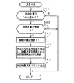
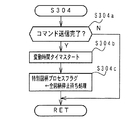
以下、上述した表示例を実現するための遊技制御手段、総合演出制御手段および表示制御手段の制御について説明する。
図29は、図16に示された特別図柄プロセス処理における全図柄変動開始待ち(ステップS304)の処理を示すフローチャートである。ステップS302,S303の停止図柄設定処理およびリーチ動作設定処理において変動時間と停止図柄が決定されると、それらを指示するための演出制御コマンドの総合演出制御基板90に対する送出制御が行われるのであるが、ステップS304では、主基板31のCPU56は、まず、コマンドの送出完了を待つ(ステップS304a)。なお、コマンド送出完了は、メイン処理(図11参照)中の制御データ出力処理(ステップS5)から通知される。
【0167】
この実施の形態では、CPU56は、図柄の変動を開始させるときに、図10に示された変動時間を特定可能な演出制御コマンドA0,A2,B1,B2,B3のいずれかを総合演出制御基板90に送出する。また、続けて、既に決定されている左右中の停止図柄を示す演出制御コマンドを総合演出制御基板90に送出する。よって、ステップS304aのコマンド送信完了処理では、それら全てのコマンドの送出が完了したか否か確認される。なお、CPU56は、左右中の停止図柄を示す演出制御コマンドを送出してからコマンドA0,A2,B1,B2,B3のいずれかを送出してもよい。
【0168】
演出制御コマンドの送出が完了すると、CPU56は、総合演出制御基板90に通知した変動時間を測定するための変動時間タイマをスタートする(ステップS304b)。そして、ステップS305(全図柄停止待ち処理)に移行するように、特別図柄プロセスフラグを更新する(ステップS304c)。
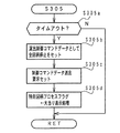
【0169】
図30は、図16に示された特別図柄プロセス処理における全図柄停止待ち処理(ステップS305)を示すフローチャートである。ステップS305では、CPU56は、変動時間タイマがタイムアップしたか否か確認する(ステップS305a)。タイムアップしたら、全図柄停止を指示する演出制御コマンドを設定する(ステップS305b)。そして、制御コマンドデータ送出要求をセットし(ステップS305c)、ステップS306(大当り表示処理)に移行するように、特別図柄プロセスフラグを更新する(ステップS305d)。なお、制御コマンドデータ送出要求は、メイン処理(図11参照)中の制御データ設定処理(ステップS4)で参照される。また、大当りとなっていない場合には、ステップS305dにおいて、ステップS300に移行するように、特別図柄プロセスフラグを更新する。
【0170】
以上のように、特別図柄プロセス処理において、CPU56は、変動の開始時に変動時間を特定可能な情報と停止図柄を指示する情報とを、総合演出制御基板90に送出し、変動時間タイマがタイムアップしたら、すなわち指示した変動時間が終了したら、全図柄停止を指示する情報(確定コマンド)を、総合演出制御基板90に送出する。その間、CPU56は、演出制御コマンドを送出しない。従って、主基板31のCPU56のコマンド送出制御に要する負荷は大きく低減されている。
【0171】
図31は、図16に示された特別図柄プロセス処理における大当り表示処理(ステップS306)を示すフローチャートである。ステップS306では、CPU56は、大当り発生を指示する演出制御コマンドを設定する(ステップS306b)。そして、制御コマンドデータ送出要求をセットし(ステップS306c)、ステップS307(大入賞口開放開始処理)に移行するように、特別図柄プロセスフラグを更新する(ステップS306d)。
【0172】
図32は、図16に示された特別図柄プロセス処理における大入賞口開放開始処理(ステップS307)を示すフローチャートである。ステップS307では、CPU56は、ラウンド開始を指示する演出制御コマンドを設定する(ステップS307a)。そして、制御コマンドデータ送出要求をセットする(ステップS307b)。ラウンド開始を指示する演出制御コマンドの2バイト目にはラウンド数が設定される。次いで、大入賞口を開放するためのソレノイド21をオンして(ステップS307c)、ステップS308(大入賞口開放中処理)に移行するように、特別図柄プロセスフラグを更新する(ステップS307d)。
【0173】
図33は、図16に示された特別図柄プロセス処理における大入賞口開放中処理(ステップS308)を示すフローチャートである。ステップS308では、CPU56は、Vカウントスイッチ22がオンしたか否か確認する(ステップS308a)。オンしたら、V入賞を指示する演出制御コマンドを設定し(ステップS308b)、制御コマンドデータ送出要求をセットする(ステップS308c)。
【0174】
また、CPU56は、ラウンド終了条件が成立したか否か確認する(ステップS308d)。ラウンド終了条件は、大入賞口に所定数の遊技球が入賞した場合、または、所定時間が経過した場合である。ラウンド終了条件が成立した場合には、ソレノイド21をオフし(ステップS308e)、ラウンド終了を指示する演出制御コマンドを設定し(ステップS308f)、制御コマンドデータ送出要求をセットする(ステップS308g)。
【0175】
そして、大当り遊技を継続すべきか否か判定し(ステップS308h)、継続すべきと判断した場合には、所定期間のディレイ時間をおいてから(ステップS308i)、ステップS307(大入賞口開放開始処理)に移行するように、特別図柄プロセスフラグを更新する(ステップS308j)。なお、大入賞口開放中処理では、大入賞口への入賞を検知するカウントスイッチ22のオンが検出されたら、大入賞口入賞を示す演出制御コマンドが総合演出制御基板90に送出される。
【0176】
大当り遊技終了と判断した場合には、CPU56は、ステップS309(大当り終了処理)に移行するように、特別図柄プロセスフラグを更新する(ステップS308k)。なお、ラウンド数が所定回に達した場合、またはラウンド中に規定湖までの入賞がなかった場合等に、大当り遊技終了と判断される。
【0177】
図34は、図16に示された特別図柄プロセス処理における大当り終了処理(ステップS309)を示すフローチャートである。ステップS309では、CPU56は、大当り終了を指示する演出制御コマンドを設定する(ステップS309a)。そして、制御コマンドデータ送出要求をセットし(ステップS309b)、ステップS300に移行するように、特別図柄プロセスフラグを更新する(ステップS309c)。
【0178】
大当り終了処理では、確変フラグがセットされている場合には、確変開始の演出制御コマンド(B0H,01H)を総合演出制御基板90に送出する制御を行う。また、高確率状態であって、その状態の終了条件(例えば、規定回変動が行われた)が成立していたら、確変終了の演出制御コマンド(B0H,02H)を総合演出制御基板90に送出する制御を行う。
【0179】
以上に説明したように、この実施の形態では、遊技制御手段すなわち主基板31のCPU56は、特別遊技装置(この例では可変表示部9)の作動に関する大まかな情報と、大当り遊技中における遊技状態を示す情報を総合演出制御基板90に演出制御コマンドとして送出する。この実施の形態では、特別遊技装置の作動に関する情報とは、可変表示の変動時間を特定可能な情報と作動結果(この例では確定図柄)を示す情報である。また、大当り遊技中における遊技状態を示す情報は、大当り発生、大当り終了、ラウンド開始、ラウンド終了、V入賞、大入賞口入賞、確変開始および確変終了等の演出制御コマンドである。
【0180】
総合演出制御基板90における演出制御用CPU89は、主基板31から受信した特別遊技装置の作動に関する情報にもとづいて、複数種類用意されている所定の演出制御のうちから1つの演出制御を独自に決定する。そして、決定した演出制御を示す表示制御コマンドおよびランプ制御コマンドを、表示制御基板80およびランプ制御基板35に送出する。以下に説明するように、この実施の形態では、所定の演出制御として、リーチ種類や予告がある。すなわち、演出制御用CPU89は、変動時間を特定可能な演出制御コマンドを受信したら、具体的なリーチ種類を決定する。例えば、リーチ短期間の演出制御コマンドを受信したら、図25に示されたパターンA〜Cのいずれの変動態様を用いるのかを決定する。また、受信した演出制御コマンドにもとづいてリーチとすることを認識したら、リーチ予告を行うのかと大当り予告を行うのかを決定する。リーチとしないことを認識したら、リーチ予告を行うのかを決定する。
【0181】
表示制御基板80の表示制御用CPU101は、総合演出制御基板90から受信した表示制御コマンドに応じて図柄の可変表示を実行する。その際、変動態様に応じた背景およびキャラクタを使用することに決定する。
【0182】
なお、この実施の形態では、各変動態様に応じて、用いられる背景およびキャラクタがあらかじめ決まっていた(図25〜図28参照)。従って、演出制御用CPU89が、主基板31から受信した演出制御コマンドに応じて変動態様(具体的なリーチ種類)を決定するということは、表示される背景およびキャラクタを、それぞれ複数種類のうちから選択する処理も行われたことになる。すなわち、演出制御のうち背景およびキャラクタも、演出制御用CPU89によって決定されることになる。しかし、演出制御用CPU89または表示制御用CPU101が、背景およびキャラクタを変動態様とは独立に決定するようにしてもよい。なお、この実施の形態では、どの変動態様においてもキャラクタが表示されるが、ある変動態様ではキャラクタを登場させなかったり、途中から登場させるようにしてもよい。
【0183】
また、この実施の形態では演出制御用CPU89が具体的なリーチ種類を決定するが、表示制御用CPU101がリーチ種類を決定するようにしてもよい。さらに、演出制御用CPU89が予告を行うか否かを決定するを決定するが、表示制御用CPU101が予告を行うか否かを決定するように構成してもよい。
【0184】
以下、演出制御用CPU89の動作を説明する。
図35は、演出制御用CPU89のメイン処理を示すフローチャートである。メイン処理では、演出制御用CPU89は、まず、RAMおよびI/Oポート等を初期化する(ステップS701)。その後、ステップS703の表示用乱数更新処理(表示用乱数を生成するカウンタの更新処理)を繰り返し実行する。
【0185】
図36は、演出制御用CPU89が扱う表示用乱数を示す説明図である。図36に示すように、この実施の形態では、表示用乱数として、リーチ種類決定用乱数、リーチ予告用乱数および大当り予告用乱数がある。リーチ種類決定用乱数は変動態様(リーチ種類)を決定するためのものである。リーチ予告用乱数はリーチ予告を行うか否か決定するためのものであり、大当り予告用乱数は大当り予告を行うか否か決定するためのものである。
【0186】
図37は、抽出されたリーチ種類決定用乱数値とリーチ種類との関係を示す説明図である。図37において、A,B,Cは、図25〜図28における(A),(B),(C)に対応している。すなわち、抽出されたリーチ種類決定用乱数の値が上段に示される値であれば、演出制御用CPU89は、下段に示された変動態様で図柄の変動を行うことに決定する。例えば、主基板31から変動時間として29.5秒(リーチ長期間)が通知され、抽出したリーチ種類決定用乱数の値が21であり、大当りとする場合には、図28(C)に示された変動態様で変動を行うことに決定する。なお、大当りとするか否かは、変動時間を指定する表示制御コマンドともに送出された左右中図柄の停止図柄を示す演出制御コマンドにもとづいて判定される。
【0187】
図38は、抽出されたリーチ予告用乱数とリーチ予告との関係(図38(A))、抽出された大当り予告用乱数と大当り予告との関係(図38(B))を示す説明図である。この実施の形態では、リーチとすることを示す演出制御コマンドを受信した場合には、演出制御用CPU89は、リーチ予告用乱数を抽出し、その値が0〜3のいずれかであればリーチ予告を行わないことに決定し、抽出値が4または5であればリーチ予告1の態様でリーチ予告を行うことに決定し、抽出値が6または7であればリーチ予告2の態様でリーチ予告を行うことに決定する。
【0188】
また、はずれとすることを示す演出制御コマンドを受信した場合に、演出制御用CPU89は、リーチを成立させる左右図柄が1図柄ずれているときには、リーチ予告用乱数の抽出値が0〜5のいずれかであればリーチ予告を行わないことに決定し、抽出値が6であればリーチ予告1の態様でリーチ予告を行うことに決定し、抽出値が7であればリーチ予告2の態様でリーチ予告を行うことに決定する。図柄のずれ数が2図柄以上であるときには、リーチ予告用乱数の抽出値が0〜6のいずれかであればリーチ予告を行わないことに決定し、抽出値が7であればリーチ予告1の態様でリーチ予告を行うことに決定する。
【0189】
さらに、リーチとすることを示す演出制御コマンドを受信した場合には、演出制御用CPU89は、大当り予告用乱数を抽出し、大当りとする場合には、その値が0であれば大当り予告を行わないことに決定し、抽出値が1であれば大当り予告1の態様で大当り予告を行うことに決定し、抽出値が2であれば大当り予告2の態様で大当り予告を行うことに決定する。
【0190】
また、大当りとしない場合に、左右図柄と中図柄とが1図柄ずれているときには、大当り予告用乱数値が0であれば大当り予告を行わないことに決定し、抽出値が1であれば大当り予告1の態様で大当り予告を行うことに決定し、抽出値が2であれば大当り予告2の態様で大当り予告を行うことに決定する。左右図柄と中図柄とのずれ数が2図柄以上であるときには、大当り予告用乱数の抽出値が0または1であれば大当り予告を行わないことに決定し、抽出値が2であれば大当り予告1の態様で大当り予告を行うことに決定する。
【0191】
なお、1図柄ずれているか否かは、主基板31から受信した停止図柄(確定図柄)を示す演出示制御コマンドによって判定可能である。このように、この実施の形態では、総合演出制御手段は、表示演出として「予告」の実行も決定する。そして、「予告」の表示演出の実行を決定する際に、確定図柄を示す演出制御コマンドにもとづいて「予告」を行うか否か決定するので、可変表示部9において最終的に確定する図柄に応じた予告実行判断を行うことができる。例えば、図38に示されているように、確定図柄の組み合わせが1図柄ずれている場合には、「予告」が生じやすくなっている。
【0192】
この実施の形態では、主基板31からの演出制御コマンドは、割込処理によって演出制御用CPU89に受信される。すなわち、主基板31からのINT信号が、演出制御用CPU89の割込端子に導入されている。図39は、演出制御用CPU89の割込処理を示すフローチャートである。割込処理において、演出制御用CPU89は、まず、データ受信中フラグがセットされているか否か確認する(ステップS601)。セットされていなければ、この割込が演出制御コマンドデータにおける第1バイトの演出制御データ送出による割込である。そこで、ポインタをクリアするとともに(ステップS602)、データ受信中フラグをセットする(ステップS603)。そして、ステップS604に移行する。ポインタは、演出制御用CPU89が内蔵しているRAMにおける演出制御コマンドデータ格納エリアにおける何バイト目に受信データを格納するか指し示すものである。
【0193】
データ受信中フラグがセットされている場合には、ストローブ信号(INT信号)がオフしたら(ステップS604)、演出制御用CPU89は、入力ポートからデータを入力し、演出制御コマンドデータ格納エリアにおいてポインタによって示されているアドレスに、入力データを格納する(ステップS605)。
【0194】
そして、演出制御用CPU89は、ポインタの値を+1する(ステップS606)。そして、ポインタの値が2になった場合には(ステップS607)、2バイトで構成される演出制御コマンドデータの受信が完了したことになるので、データ受信完了フラグをセットするとともに、データ受信中フラグをリセットする(ステップS608,S609)。以上のような処理によって、演出制御データCMD1,CMD2が、総合演出制御基板90において受信される。なお、この実施の形態では、演出制御用CPU89は、割込処理によって演出制御コマンドを受信したが、主基板31からのINT信号(ストローブ信号)を入力する入力ポートを監視することによって演出制御コマンドを受信するようにしてもよい。
【0195】
上述したように、演出制御用CPU89は、主基板31から変動時間を特定可能な演出制御コマンドを受信したら具体的な変動態様を決定する。また、リーチ予告を行うか否かと大当り予告を行うか否かとを決定する。すなわち、演出制御用CPU89は演出内容の決定を行う。そして、演出内容の決定結果に応じた制御コマンドを表示制御基板80およびランプ制御基板35に送出する。図40は、演出制御用CPU89が、表示制御基板80およびランプ制御基板35に送出する制御コマンドのうち、演出制御用CPU89が決定した遊技演出に関わるものを示す説明図である。なお、この実施の形態では、はずれ変動は1種類であり、確変時のはずれ変動も1種類であるので、それらについては演出制御用CPU89が複数種類のうちから選択することはないが、それらに関する制御コマンドも演出制御用CPU89が決定した遊技演出に関わるものに含める。
【0196】
また、図40に示されたもの以外の制御コマンドについては、主基板31から受信した演出制御コマンドを、そのまま表示制御基板80およびランプ制御基板35に送出する制御コマンドとして用いるとする。すなわち、演出制御用CPU89は、図10に示された[80H,00H]以外の演出制御コマンドを受信すると、それらのコマンドを、それらに対応する表示制御基板80およびランプ制御基板35に対する制御コマンドとして送出する。もちろん、演出制御コマンドと、それに対応する表示制御基板80およびランプ制御基板35に対する制御コマンドとを、異なるビット構成としてもよい。
【0197】
変動態様に関する情報と予告ありなしを示す情報とが1つの制御コマンドに含まれていてもよいが、その場合には、例えば、図41に示すように、変動態様、リーチ予告の有無および大当り予告の有無が1制御コマンドで指定される。ただし、図41には、変動態様および予告に関する制御コマンドのうちの一部のみが例示されている。
【0198】
この実施の形態では、演出制御用CPU89は、タイマ割込処理で、表示制御基板80およびランプ制御基板35に対する制御コマンドを送出する。タイマ割込は、例えば、2ms毎に繰り返しかかるように設定される。図42は、タイマ割込処理を示すフローチャートである。タイマ割込処理では、表示制御基板80およびランプ制御基板35に対する制御コマンドをRAMに形成されたバッファ領域に格納する制御コマンド設定処理(ステップS711)と、バッファ領域に格納された制御コマンドを送出する制御コマンド出力処理(ステップS712)とが実行される。
【0199】
図43は、総合演出制御基板90から表示制御基板80およびランプ制御基板35に送信される制御コマンドを示す説明図である。図43に示すように、この実施の形態では、制御コマンドは、制御データCD0〜CD7の8本のデータ線で総合演出制御基板90から表示制御基板80およびランプ制御基板35に送信される。また、総合演出制御基板90と表示制御基板80およびランプ制御基板35との間には、INT信号を送信するためのINT信号の信号線も配線されている。
【0200】
図44は、総合演出制御基板90から表示制御基板80およびランプ制御基板35に与えられる制御コマンドの送出タイミングを示すタイミング図である。図44に示すように、タイマ割込の発生間隔が2msであるとすると、2msにおいて1つの制御コマンドが送出される。制御コマンドの各バイトが出力されてから800μs間INT信号がオン状態(ローレベル)になる。表示制御用CPU101およびランプ制御用CPU351は、INT信号がオンしたことを検出すると、制御コマンドを取り込む処理を行う。
【0201】
この実施の形態では、制御コマンドは2バイト構成であるから、1つの制御コマンドが出力される際に、2回INT信号が出力される。なお、制御コマンドは2バイト構成に限られず、情報量に応じて2バイト以上であってもよい。
【0202】
図45は、例えば2ms毎にかかるタイマ割込処理で起動される制御コマンド設定処理(ステップS711)を示すフローチャートである。制御コマンド設定処理において、演出制御用CPU89は、まず、主基板31から演出制御コマンドを受信したか否か確認する(ステップS721)。受信していたら、その1バイト目が90H〜92Hのいずれかであるか確認する(ステップS722)。1バイト目が90H〜92Hである演出制御コマンドは、左右中図柄の確定図柄を示すコマンドである(図10参照)。1バイト目が90H〜92Hである演出制御コマンドを受信した場合には、受信したコマンドを図柄保存領域に保存する(ステップS723)。また、受信したコマンドをポート格納領域に設定し(ステップS724)、ポート出力要求をセットする(ステップS733)。
【0203】
受信した演出制御コマンドの1バイト目が80Hであれば、すなわち、変動時間を特定可能かコマンドを受信した場合には、演出制御用CPU89は、左右中図柄の確定図柄を示すコマンドを既に受信しているか否か確認する(ステップS726)。受信していれば、変動態様を決定する(ステップS727)。すなわち、リーチ変動を示す演出制御コマンド(リーチ期間を特定可能なコマンド)を受信した場合には、図37に示されたテーブル内容に従ってリーチ種類を決定する。そして、決定した変動態様に応じた制御コマンドをポート格納領域に設定する(ステップS728)。
【0204】
また、図38に示されたテーブル内容に従ってリーチ予告を行うか否かと予告種類を決定する(ステップS729)。そして、決定したリーチ予告種類に応じた制御コマンドをポート格納領域に設定する(ステップS730)。さらに、図38に示されたテーブル内容に従って大当り予告を行うか否かと予告種類を決定する(ステップS731)。そして、決定した大当り予告種類に応じた制御コマンドをポート格納領域に設定する(ステップS732)。さらに、ポート出力要求をセットする(ステップS733)。
【0205】
なお、ステップS728、S730およびS732の各処理で複数の制御コマンドがポート格納領域に設定されることになるので、ポート格納領域として、複数個の制御コマンドが格納できるような領域が確保される。後述する制御コマンド出力処理では、ポート格納領域に複数個の制御コマンドが格納されている場合には、それらを順次送出する制御を行う。
【0206】
また、この実施の形態では、変動態様を示す制御コマンドと予告を示す制御コマンドとは別個に送出されることになるが、図41に例示したように、変動態様に関する情報と予告ありなしを示す情報とを1つの制御コマンドで送出してもよい。
【0207】
受信した演出制御コマンドの1バイト目が80Hでもない場合には、演出制御用CPU89は、受信した演出制御コマンドをそのままポート格納領域に設定し(ステップS734)、ポート出力要求をセットする(ステップS733)。
【0208】
図46は、例えば2ms毎にかかるタイマ割込処理で起動される制御コマンド出力処理(ステップS712)を示すフローチャートである。制御コマンド設定出力において、演出制御用CPU89は、ポート出力要求がセットされているか否か判定する(ステップS771)。ポート出力要求がセットされている場合には、ポート出力要求をリセットし(ステップS772)、ポート格納領域の内容(制御コマンドの1バイト目)を出力ポート91,93に出力する(ステップS773)。出力ポート91から出力される制御コマンドは表示制御コマンドとなり、出力ポート93から出力される制御コマンドはランプ制御コマンドとなる(図5参照)。
【0209】
そして、各基板80,35に至るINT信号をローレベル(オン状態)にし(ステップS774)、800μsタイマをスタートさせて(ステップS775)、制御コマンドの1バイト目送出中であることを示すCMD1送出中フラグをオンする(ステップS776)。
【0210】
図47は、800μタイマ割込処理を示すフローチャートである。800μタイマ割込処理は、上述したステップS775または後述するステップS788で設定された800μsタイマのタイムアウトによって起動される。800μタイマ割込処理において、演出制御用CPU89は、まず、CMD1送出中フラグがオンしているか否か確認する(ステップS781)。オンしていれば、CMD1送出中フラグをリセットし(ステップS782)、INT信号をハイレベル(オフ状態)にし(ステップS783)、所定期間のディレイタイムをおいて(ステップS784)、ポート格納領域の内容(制御コマンドの2バイト目)を出力ポート91,93に出力する(ステップS785)。
【0211】
なお、ディレイタイムは、図44に示されたINT信号の出力タイミングにおける1回目のINT信号のオン期間と2回目のINT信号のオン期間との間のオフ期間を作成するための時間である。
【0212】
そして、INT信号をローレベル(オン状態)にし(ステップS786)、制御コマンドの2バイト目送出を示すCMD2送出中フラグをセットし(ステップS787)、800μsタイマをスタートさせる(ステップS788)。
【0213】
ステップS781において、CMD1送出中フラグがセットされていない場合には、演出制御用CPU89は、CMD2送出中フラグがオンしているか否か確認する(ステップS791)。オンしていれば、CMD2送出中フラグをリセットし(ステップS792)、INT信号をハイレベル(オフ状態)にする(ステップS793)。
以上のようにして、図44に示されたようなタイミングで、制御コマンドが表示制御基板80およびランプ制御基板35に送出される。
【0214】
なお、図46および図47に示されたように、800μsタイマ割り込みによってINT信号のオン/オフ制御を実行する方法は一例であって、他の方法を用いてもよい。例えば、メイン処理の随所で割込によらずINT信号のオン/オフ制御を行ってもよい。いずれにせよ、図44に示されたようなタイミングで同一の制御コマンドが主基板31から表示制御基板80およびランプ制御基板35に送出されればよい。なお、INT信号のオン期間である800μsも一例であって、機種に応じて任意に設定することができる。
【0215】
図48は、表示制御基板80における表示制御用CPU101およびランプ制御基板35におけるランプ制御用CPU351のそれぞれが実行する制御コマンド読込動作を示すフローチャートである。制御コマンド読込処理において、各CPU101,351は、制御コマンドデータの入力に割り当てられている入力ポートから1バイトのデータを読み込む(ステップS121)。次に、INT信号の入力に割り当てられている入力ポートからINT信号の状態を読み取る(ステップS122)。上述したように、INT信号は、総合演出制御基板90の演出制御用CPU89が新たな制御コマンドデータを出力したときにローレベルとされる。
【0216】
INT信号がオフしている場合には、通信カウンタをクリアする(ステップS126)。通信カウンタは、INT信号がオンしているときの制御コマンドデータ受信回数をカウントするために用いられる。
【0217】
INT信号がオンしている場合には、受信した制御コマンドデータが直前に(100μs前)受信したコマンドデータと同じか否か確認する(ステップS123)。同じでない場合には、通信カウンタをクリアする(ステップS126)。同じであった場合には、通信カウンタが所定の最大値(MAX)に達しているか否か確認する(ステップS124)。
【0218】
最大値に達していない場合には、通信カウンタの値を+1する(ステップS125)。ここで、最大値とは、制御コマンドデータを確実に受信したと判定する値(この例では3)よりも大きい値であり、例えば、800μs間での受信回数をカウントする等の目的で用いられる。
【0219】
次いで、各CPU101,351は、通信カウンタ後が「3」になったか否か確認する(ステップS127)。「3」になっている場合には、受信したデータが制御コマンドの1バイト目(CMD1)であるのか2バイト目(CMD2)であるのかを確認する(ステップS128)。1バイト目であれば、受信したデータを受信コマンド格納エリア(1バイト目)に格納し(ステップS129)、コマンド受信中フラグをセットする(ステップS130)。そして、受信したデータをワークエリアに格納する(ステップS134)。
【0220】
受信したデータが制御コマンドの2バイト目であれば、受信したデータを受信コマンド格納エリア(2バイト目)に格納し(ステップS131)、コマンド受信中フラグをリセットする(ステップS132)。そして、通信終了フラグをセットする(ステップS133)。また、受信したデータをワークエリアに格納する(ステップS134)。「3」になっていない場合には、通信終了フラグをセットせずに、読み取ったデータをワークエリアに格納する(ステップS134)。なお、ワークエリアに格納されたデータは、次の割込処理において、ステップS123において用いられる。
【0221】
以上の処理によって、総合演出制御基板90から送出された制御コマンドは、表示制御用CPU101およびランプ制御用CPU351に読み込まれる。
【0222】
この実施の形態では、複数回連続して同一コマンドを受信できたら正しいコマンドを受信できたと判定することによってノイズの影響を防止し、コマンド受信期間を制御コマンドデータ変更後の短い期間に限定することによって、ノイズの影響をより効果的に防止する。なお、この実施の形態では3回連続して同一コマンドを受信できたら正しいコマンドを受信できたと判定したが、必要に応じて、複数回は2回または4回以上であってもよい。また、この実施の形態ではINT信号を監視することによって制御コマンドを確認したが、INT信号を割込端子に導入し割込処理で制御コマンドを受信することもできる。
【0223】
図49は、表示制御基板80におけるROM等に格納されているコマンドデータテーブルの構成例を示す説明図である。コマンドデータテーブルとは、表示制御手段が総合演出制御手段から受信するコマンド定義が記載されたテーブルである。ただし、コマンドデータテーブルには、そのコマンドを受信しても制御に影響を与えないコマンドについては「変化なし」を示すデータが記載されている。この例では、普図始動入賞コマンド(A0H,XXH)、普図変動開始コマンド(A1,XXH)および特図始動入賞コマンド(C0H,XXH)が「変化なし」に対応する。なお、コマンドデータテーブルにおける80XX等は、80H,XXHの意味である。
【0224】
表示制御用CPU101は、総合演出制御基板90から受信した表示制御コマンドの1バイト目がA0HまたはC0Hである場合には、そのときに行っていた表示制御を続行する。また、受信した表示制御コマンドの1バイト目が90H、91Hまたは92Hであれば、受信コマンドに対応した図柄を特定する情報を保存する。その他の表示制御コマンドを受信した場合には、各コマンドに応じて決められている表示制御を開始する。
【0225】
次に、表示制御用CPU101の動作を説明する。
図50は、表示制御用CPU101のメイン処理を示すフローチャートである。メイン処理では、表示制御用CPU101は、まず、RAM、I/OポートおよびVDP103等を初期化する(ステップS801)。そして、その後ループする。この実施の形態では、表示制御用CPU101は、可変表示部9に表示制御と音制御基板70に対する音制御コマンド送出制御を、定期的に(例えば2ms毎に)発生するタイマ割込で実行する。
【0226】
図51は、タイマ割込処理を示すフローチャートである。タイマ割込処理において、表示制御用CPU101は、可変表示部9の表示制御のための表示制御プロセス処理(ステップS811)、音制御基板70に対する音制御コマンドを作成するための音制御コマンド設定処理(ステップS812)および音制御コマンドを送出するための音制御コマンド出力処理(ステップS813)を行う。
【0227】
図52は、図51に示されたタイマ割込処理における表示制御プロセス処理(ステップS811)を示すフローチャートである。表示制御プロセス処理では、表示制御プロセスフラグの値に応じてステップS720〜S870のうちのいずれかの処理が行われる。各処理において、以下のような処理が実行される。
【0228】
表示制御コマンド受信待ち処理(ステップS720):変動態様を特定可能な表示制御コマンドを受信したか否か確認する。
【0229】
全図柄変動開始処理(ステップS780):左右中図柄の変動が開始されるように制御する。
【0230】
図柄変動中処理(ステップS810):変動態様を構成する各変動状態(変動速度や背景、キャラクタ)の切替タイミングを制御するとともに、変動時間の終了を監視する。また、左右図柄の停止制御を行う。
【0231】
全図柄停止待ち設定処理(ステップS840):変動時間の終了時に、全図柄停止を指示する表示制御コマンドを受信していたら、図柄の変動を停止し最終停止図柄(確定図柄)を表示する制御を行う。
【0232】
大当り表示処理(ステップS870):変動時間の終了後、確変大当り表示または通常大当り表示の制御等を行う。さらに、大当り遊技中に、受信した表示制御コマンドにもとづいてラウンド表示、大入賞口入賞数表示およびV入賞表示等を行う。
以上の表示制御プロセス処理における各処理では、総合演出制御基板90から受信した表示制御コマンドに応じた表示制御を行うのであるが、具体的な処理内容は図49に示されたとおりである。
【0233】
図53は、図51に示されたタイマ割込処理における音制御コマンド設定処理(ステップS812)を示すフローチャートである。音制御コマンド設定処理において、表示制御用CPU101は、まず、総合演出制御基板90から表示制御コマンドを受信したか否か確認する(ステップS821)。上述したように、表示制御用CPU101は、表示制御コマンドを受信すると表示制御プロセス処理で、受信したコマンドに応じた表示制御を行うのであるが、それとともに、受信した表示制御コマンドに対応した音制御コマンドを作成する。なお、この実施の形態では、音制御コマンドのビット構成は、受信した表示制御コマンドのビット構成と同じであるとする。
【0234】
表示制御用CPU101は、表示制御コマンドを受信していれば、受信コマンドを、音制御コマンド送出用のポート格納領域(RAM領域)に格納する(ステップS822)。そして、ポート出力要求をセットする(ステップS823)。
【0235】
図54は、図51に示されたタイマ割込処理における音制御コマンド出力処理(ステップS813)を示すフローチャートである。音制御コマンド出力処理において、表示制御用CPU101は、ポート出力要求がセットされているか否か判定する(ステップS871)。ポート出力要求がセットされている場合には、ポート出力要求をリセットし(ステップS872)、ポート格納領域の内容(制御コマンドの1バイト目)を出力ポート108(図7参照)に出力する(ステップS873)。
【0236】
そして、音制御基板70に至るINT信号をローレベル(オン状態)にし(ステップS874)、800μsタイマをスタートさせて(ステップS875)、制御コマンドの1バイト目送出中であることを示すCMD1送出中フラグをオンする(ステップS876)。
【0237】
図55は、800μタイマ割込処理を示すフローチャートである。800μタイマ割込処理は、上述したステップS875または後述するステップS888で設定された800μsタイマのタイムアウトによって起動される。800μタイマ割込処理において、表示制御用CPU101は、まず、CMD1送出中フラグがオンしているか否か確認する(ステップS881)。オンしていれば、CMD1送出中フラグをリセットし(ステップS882)、INT信号をハイレベル(オフ状態)にし(ステップS883)、所定期間のディレイタイムをおいて(ステップS884)、ポート格納領域の内容(制御コマンドの2バイト目)を出力ポート108に出力する(ステップS885)。
【0238】
なお、ディレイタイムは、2バイト構成の1つの音制御コマンドに対する1回目のINT信号のオン期間と2回目のINT信号のオン期間との間のオフ期間を作成するための時間である。
【0239】
そして、INT信号をローレベル(オン状態)にし(ステップS886)、制御コマンドの2バイト目送出を示すCMD2送出中フラグをセットし(ステップS887)、800μsタイマをスタートさせる(ステップS888)。
【0240】
ステップS881において、CMD1送出中フラグがセットされていない場合には、表示制御用CPU101は、CMD2送出中フラグがオンしているか否か確認する(ステップS891)。オンしていれば、CMD2送出中フラグをリセットし(ステップS892)、INT信号をハイレベル(オフ状態)にする(ステップS893)。
【0241】
図56は、表示制御基板80から音制御基板70に送信される音制御コマンドを示す説明図である。図56に示すように、この実施の形態では、音制御コマンドは、制御データCD0〜CD7の8本のデータ線で表示制御基板80から音制御基板70に送信される。また、表示制御基板80と音制御基板70との間には、INT信号を送信するためのINT信号の信号線も配線されている。
【0242】
図57は、表示制御基板80から音制御基板70に与えられる音制御コマンドの送出タイミングを示すタイミング図である。図53〜図55に示す処理によって、この実施の形態では2msのタイマ割込発生間隔において1つの音制御コマンドが送出される。音演出制御基板70の音制御用CPU701は、INT信号がオンしたことを検出すると、音制御コマンドを取り込む処理を行う。取り込み方は、例えば、図46に示された処理と同じでよい。
【0243】
図58は、音制御基板70におけるROM等に格納されているコマンドデータテーブルの構成例を示す説明図である。音制御基板70におけるコマンドデータテーブルには、音制御手段が表示制御手段から受信するコマンドが記載されているが、コマンドデータテーブルには、そのコマンドを受信しても制御に影響を与えないコマンドについては「変化なし」を示すデータが記載されている。この例では、確定図柄に関するコマンド(1バイト目が90H、91Hまたは92H)、普図始動入賞コマンド(A0H,XXH)、普図変動開始コマンド(A1,XXH)およびデモ・確変に関するコマンド(1バイト目がB0H)が「変化なし」に対応する。
【0244】
従って、音制御用CPU701は、受信した音制御コマンドの1バイト目が90H、91H、92H、A0H、A1HまたはB0Hである場合には、そのときに行っていた音表示制御を続行する。その他の音制御コマンドを受信した場合には、各コマンドに応じて決められているパターンの音発生制御を開始する。
【0245】
以上のように、この実施の形態では、表示制御手段が、受信した表示制御コマンドにもとづいて音制御コマンドを作成して音制御基板70に送出する。従って、遊技制御手段は、表示制御基板80と音制御基板70のそれぞれにコマンドを送出する必要はなく、コマンド送出に要する負荷が低減される。
【0246】
また、この実施の形態では、表示制御手段は、総合演出制御手段から受信した演出制御コマンドと同一のコマンドを音制御コマンドとして音制御手段に対して送出する。そして、音制御手段は、音発生制御に影響を与えないコマンドを受信した場合には、受信コマンドを無視してそのときに行っていた音制御を継続する。しかし、表示制御手段が、音制御手段が必要とするコマンドのみを送出するようにしてもよい。
【0247】
また、この実施の形態では、総合演出制御手段が受信した演出制御コマンドにもとづいて具体的な変動態様を決定した。しかし、総合演出制御手段は、受信した変動期間を特定可能なコマンドを表示制御手段に与えて、表示制御手段が具体的な変動態様を決定するように構成してもよい。また、予告演出等を実行するか否かと予告種類とを表示制御手段が決定してもよい。そのように、表示制御手段が表示演出を決定する場合には、表示制御手段は、表示演出の決定を行うとともに、決定した表示演出に応じた音制御コマンドを作成する。
【0248】
さらに、変動態様や予告の有無および予告種類等の演出内容を、総合演出制御手段と表示制御手段とが分担して決定するようにしてもよい。例えば、総合演出制御手段が変動態様を決定し、表示制御手段が予告の有無および予告種類を決定するようにしてもよい。
【0249】
図59は、ランプ制御基板35におけるROM等に格納されているコマンドデータテーブルの構成例を示す説明図である。ランプ制御基板35におけるコマンドデータテーブルにも、ランプ制御手段が総合演出制御手段から受信するコマンドが記載されているが、コマンドデータテーブルには、そのコマンドを受信しても制御に影響を与えないコマンドについては「変化なし」を示すデータが記載されている。例えば、予告に関するランプ制御コマンド(1バイト目がE0H)および確定図柄に関するランプ制御コマンド(1バイト目が90H、91Hまたは92H)については、「変化なし」を示すデータが記載されている。
【0250】
従って、ランプ制御用CPU351は、受信した制御コマンドの1バイト目が90H、91H、92HまたはE0Hである場合には、そのときに行っていたランプ表示制御を続行する。その他のランプ制御コマンドを受信した場合には、各コマンドに応じて決められているパターンのランプ表示制御を開始する。
【0251】
以上のように、この実施の形態では、総合演出制御手段は、音制御手段が搭載されている音制御基板以外の複数の制御基板に対して、遊技進行に応じて同一の制御コマンドを送出する。その場合、送出される制御コマンドのうちに、ある制御手段の制御状態を変化させない余剰の制御コマンドが含まれていることを許容する。そして、各制御手段は、受信した制御コマンドのうち必要なコマンドのみを選択し、選択したコマンドに応じた制御を行う。従って、遊技制御手段は、ある制御基板に対して制御コマンドを送出する必要があるか否か判断する必要がなくなり、総合演出制御手段の制御コマンド送出に要する負荷が軽減される。
【0252】
また、各制御手段が受信した制御コマンドのうち必要なコマンドを選択する際に、制御コマンドの一部のみを判断することによって、必要なコマンドか否かを判定することができる。よって、各制御手段の受信コマンド判定処理も簡略化される。
【0253】
なお、この実施の形態では、コマンドデータテーブルに「変化なし」と記載されているものについては、その制御コマンドを受信してもそのときに行われていた制御を続行するので、不必要な制御コマンドの取り扱いも容易であるが、不必要なコマンドについてはコマンドデータテーブルに記載せず、コマンドデータテーブルに存在しないものについては受信コマンドを無視するように構成してもよい。
【0254】
なお、図5に示されたように、上記の実施の形態では、総合演出制御基板90には、表示制御基板80に送出される制御コマンドのための出力ポート91およびランプ制御基板35に送出される制御コマンドのための出力ポート93が別個に設けられていた。しかし、各基板に全く同一の制御コマンドを送出する場合には、出力ポートは1つであってもよい。
【0255】
上記の各実施の形態のパチンコ遊技機1は、始動入賞にもとづいて可変表示部9に可変表示される特別図柄の停止図柄が所定の図柄の組み合わせになると所定の遊技価値が遊技者に付与可能になる第1種パチンコ遊技機であったが、始動入賞にもとづいて開放する電動役物の所定領域への入賞があると所定の遊技価値が遊技者に付与可能になる第2種パチンコ遊技機や、始動入賞にもとづいて可変表示される図柄の停止図柄が所定の図柄の組み合わせになると開放する所定の電動役物への入賞があると所定の権利が発生または継続する第3種パチンコ遊技機であっても、本発明を適用できる。
【0256】
その場合、第2種パチンコ遊技機に適用された場合の電動役物の作動時間や、第3種パチンコ遊技機に適用された場合の電動役物の作動時間や停止図柄は、遊技制御手段によって決定される。可変表示される図柄の変動パターン等は、総合演出制御手段または特別遊技装置制御手段によって決定される。
【0257】
以上に説明したように、遊技の進行を制御する遊技制御手段は、遊技制御の切替時に総合演出制御基板90に対して演出制御コマンドを送出する。総合演出制御基板90に搭載されている総合演出制御手段は、受信した演出制御コマンドにもとづいて、複数の演出内容のうちから1つの演出内容を独自に決定する。そして、決定した演出内容に対応した表示制御コマンドおよびランプ制御コマンドを作成して、表示制御基板80およびランプ制御基板35に送出する。従って、遊技制御手段は複数の演出内容のうちから1つの演出内容を決定し決定した内容に応じた制御コマンドを作成する必要はないので、遊技制御手段の負荷は軽減されている。
【0258】
また、特別遊技装置の作動態様および作動結果(上述した例では可変表示部9における図柄の変動時間および確定図柄)は遊技制御手段によって決定される。従って、遊技機における遊技者に有利な状態をもたらす装置に関する制御において根幹に関わる部分は、遊技の全体的な進行を制御する遊技制御手段によって行われることになり、遊技進行において適正な制御が実現されている。
【0259】
なお、1つの演出内容しかないものについて、総合演出制御手段は、受信した演出制御コマンドに応じた表示制御コマンドおよびランプ制御コマンドを作成する。すなわち、そのような内容については、遊技制御手段によって決定される。例えば、図柄の変動時間、確定図柄、大当り遊技中(特定遊技状態中)の状態変化に関する情報(例えば、ラウンド数、大入賞口入賞数、V入賞)は、遊技制御手段によって決定され、決定された情報に応じた演出制御コマンドが総合演出制御基板90に送出される。そして、総合演出制御手段は、受信した演出制御コマンドに応じた表示制御コマンドおよびランプ制御コマンドを作成する。
【0260】
また、複数の演出内容のうちから1つの演出内容を独自に決定する処理は、特別遊技装置制御手段が行ってもよい。上述した例についてそのような処理を例示すると、総合演出制御手段は予告演出について決定せず、特別遊技装置制御手段の一例である表示制御手段が、図柄変動の開始を指示する遊技状態情報すなわち演出制御コマンドに応じた表示制御コマンドを総合演出制御手段から受信すると、予告演出を行うか否かと予告種類とを決定し、決定結果に応じて表示制御を行うとともに、音制御基板70に対して対応する音制御コマンドを送出する。表示制御手段が、予告演出を行うか否かと予告種類とを決定する際に、例えば、図38に示されたようなテーブルを用いればよい。従って、表示制御手段が予告内容を独自に決定する場合にも、表示結果に見合った予告演出決定制御を行うことができる。
【0261】
なお、表示制御手段が1つの演出内容を独自に決定する構成でも、遊技制御手段は複数の演出内容のうちから1つの演出内容を決定し決定した内容に応じた制御コマンドを作成する必要はないので、遊技制御手段の負荷は軽減される。
【0262】
【発明の効果】
以上のように、本発明によれば、遊技機を、遊技制御手段が、演出制御手段に、遊技状態を特定可能なコマンドとして、識別情報の変動開始の条件の成立に応じて、識別情報の変動を開始させるときにのみ可変表示部における識別情報の変動時間を特定するためのコマンドを出力するとともに、識別情報の変動時間が経過したときに全識別情報の停止を示すコマンドを出力し、演出制御手段が、遊技制御手段から出力された遊技状態を特定可能なコマンドに対応して制御コマンドを表示制御手段に出力する演出制御側コマンド出力手段と、遊技制御手段から出力された遊技状態を特定可能なコマンドが示す遊技状態に対応する演出内容を決定する演出内容決定手段とを含み、演出制御側コマンド出力手段は、演出内容決定手段が大当り予告演出の内容を決定した場合に、識別情報の変動時間を特定するためのコマンドに対応して出力する制御コマンドに演出内容決定手段が決定した大当り予告演出の内容に対応する情報を含めた制御コマンドを出力するか、または、識別情報の変動時間を特定するためのコマンドに対応して出力する制御コマンドとは別個に演出内容決定手段が決定した大当り予告演出の内容に対応する情報を含む制御コマンドを出力する構成としたので、遊技制御手段は、演出制御基板および表示制御基板のそれぞれにコマンドを出力する必要はなく、コマンド出力に要する負荷が低減される効果がある。
【図面の簡単な説明】
【図1】 パチンコ遊技機を正面からみた正面図である。
【図2】 パチンコ遊技機の内部構造を示す全体背面図である。
【図3】 パチンコ遊技機の遊技盤を背面からみた背面図である。
【図4】 主基板における回路構成の一例を示すブロック図である。
【図5】 主基板および総合演出制御基板における制御コマンド送受信部分の一例を示すブロック図である。
【図6】 表示制御基板内の回路構成を示すブロック図である。
【図7】 音制御基板内の回路構成を示すブロック図である。
【図8】 ランプ制御基板内の回路構成を示すブロック図である。
【図9】 主基板から送出される遊技制御に関する制御コマンドを示す説明図である。
【図10】 制御コマンドのコード割り当ての一例を示す説明図である。
【図11】 基本回路のメイン処理を示すフローチャートである。
【図12】 各乱数を示す説明図である。
【図13】 打球が始動入賞口に入賞したことを判定する処理を示すフローチャートである。
【図14】 可変表示の停止図柄を決定する処理およびリーチ種類を決定する処理を示すフローチャートである。
【図15】 大当り判定の処理を示すフローチャートである。
【図16】 特別図柄プロセス処理を示すフローチャートである。
【図17】 普通図柄プロセス処理を示すフローチャートである。
【図18】 主基板から総合演出制御基板に送信される制御コマンドを示す説明図である。
【図19】 演出制御コマンドの送出タイミングの一例を示すタイミング図である。
【図20】 制御データ出力処理Aを示すフローチャートである。
【図21】 制御データ出力処理Bを示すフローチャートである。
【図22】 制御データ出力処理Cを示すフローチャートである。
【図23】 図柄の各変動パターンを構成する変動状態を示す説明図である。
【図24】 リーチとしないはずれ時の図柄の変動の一例を示すタイミング図である。
【図25】 リーチ時の図柄の変動の一例を示すタイミング図である。
【図26】 リーチ時の図柄の変動の一例を示すタイミング図である。
【図27】 リーチ時の図柄の変動の一例を示すタイミング図である。
【図28】 リーチ時の図柄の変動の一例を示すタイミング図である。
【図29】 特別図柄プロセス処理における全図柄変動開始待ちの処理を示すフローチャートである。
【図30】 特別図柄プロセス処理における全図柄停止待ち処理を示すフローチャートである。
【図31】 特別図柄プロセス処理における大当り表示処理を示すフローチャートである。
【図32】 特別図柄プロセス処理における大入賞口開放開始処理を示すフローチャートである。
【図33】 特別図柄プロセス処理における大入賞口開放中処理を示すフローチャートである。
【図34】 特別図柄プロセス処理における大当り終了処理を示すフローチャートである。
【図35】 演出制御用CPUのメイン処理を示すフローチャートである。
【図36】 表示用乱数を示す説明図である。
【図37】 表示用乱数とリーチ態様との関係を示す説明図である。
【図38】 表示用乱数とリーチ予告態様および大当り予告態様との関係を示す説明図である。
【図39】 演出制御用CPUが実行する制御コマンド読込処理を示すフローチャートである。
【図40】 演出制御用CPUが決定した遊技演出に関わる制御コマンドを示す説明図である。
【図41】 演出制御用CPUが決定した遊技演出に関わる制御コマンドの他の例を示す説明図である。
【図42】 演出制御用CPUが実行する2msタイマ割込処理を示すフローチャートである。
【図43】 総合演出制御基板から各基板に送信される制御コマンドを示す説明図である。
【図44】 制御コマンドの送出タイミングの一例を示すタイミング図である。
【図45】 制御コマンド設定処理を示すフローチャートである。
【図46】 制御コマンド出力処理を示すフローチャートである。
【図47】 800μタイマ割込処理を示すフローチャートである。
【図48】 制御コマンド読込処理を示すフローチャートである。
【図49】 表示制御基板におけるコマンドデータテーブルの構成例を示す説明図である。
【図50】 表示制御用CPUのメイン処理を示すフローチャートである。
【図51】 表示制御用CPUが実行するタイマ割込処理を示すフローチャートである。
【図52】 表示制御プロセス処理を示すフローチャートである。
【図53】 音制御コマンド設定処理を示すフローチャートである。
【図54】 音制御コマンド出力処理を示すフローチャートである。
【図55】 表示制御用CPUが実行する800μタイマ割込処理を示すフローチャートである。
【図56】 表示制御基板から音制御基板に送信される音制御コマンドを示す説明図である。
【図57】 音制御コマンドの送出タイミングの一例を示すタイミング図である。
【図58】 音制御基板におけるコマンドデータテーブルの構成例を示す説明図である。
【図59】 ランプ制御基板におけるコマンドデータテーブルの構成例を示す説明図である。
【符号の説明】
9 可変表示部
31 遊技制御基板(主基板)
35 ランプ制御基板
53 基本回路
56 CPU
70 音制御基板
80 表示制御基板
89 演出制御用CPU
90 総合演出制御基板
101 表示制御用CPU
351 ランプ制御用CPU
91,92,93 出力ポート
701 音声制御用CPU[0001]
BACKGROUND OF THE INVENTION
The present invention relates to a gaming machine such as a pachinko gaming machine or a coin gaming machine in which a game is performed in accordance with a player's operation, and more particularly to a gaming machine in which a game is performed in accordance with a player's operation in a gaming area on a gaming board. .
[0002]
[Prior art]
As a gaming machine, a variable display device having a variable display unit whose display state can be changed is provided, and a big hit game that is advantageous to the player when the display result of the variable display unit becomes a predetermined specific display mode Some are configured to transition to a state. The variable display device has a plurality of variable display units, and is usually configured to display the display results of the plurality of variable display units at different times. For example, a plurality of pieces of identification information such as symbols are variably displayed on the variable display section. That the display result of the variable display unit is a combination of specific display modes determined in advance is usually referred to as “big hit”. Note that the game value is the right that the state of the variable winning ball device provided in the gaming area of the gaming machine is advantageous for a player who is likely to win a ball, or the advantageous state for a player. It is to generate.
[0003]
When a big hit occurs, for example, the big winning opening is opened a predetermined number of times, and the game shifts to a big hit gaming state in which a hit ball is easy to win. And in each open period, if there is a prize for a predetermined number (for example, 10) of the big prize opening, the big prize opening is closed. And the number of times the special winning opening is opened is fixed to a predetermined number (for example, 16 rounds). An opening time (for example, 29.5 seconds) is determined for each opening, and even if the number of winnings does not reach a predetermined number, the big winning opening is closed when the opening time elapses. In addition, when a predetermined condition (for example, winning in a V zone provided in the big prize opening) is not established at the time when the big prize opening is closed, the big hit game even if the predetermined number of times is not reached The state ends.
[0004]
In addition, among the combinations of “out of” display modes other than the “big hit” combination, the display results are already derived and displayed at a stage where some of the display results of the plurality of variable display portions have not yet been derived and displayed. A state in which the display mode of the variable display unit satisfies a display condition that is a combination of specific display modes is referred to as “reach”. A player plays a game while enjoying how to generate a big hit.
[0005]
The game progress in the gaming machine is controlled by game control means such as a microcomputer. The identification information, character image, and background image displayed on the variable display device are controlled by display control means that operates according to a control command from the game control means. Accordingly, the game control means for controlling the progress of the game needs to transmit a display control command to the display control means.
[0006]
In addition, the game board is provided with light emitters such as lamps and LEDs, and these light emitters are turned on and off as the game progresses in order to enhance the game effect. The lighting and extinguishing of the light emitters are controlled by the game control means or the light emitter control means that receives a control command from the game control means. Further, the game board is provided with a speaker, and various sound effects are emitted from the speaker as the game progresses in order to enhance the game effect. The sound generation is controlled by game control means or by sound control means for receiving a control command from the game control means.
[0007]
In general, the switching timing control of the light emitter on / off pattern and the switching control of the sound effect pattern are performed by game control means for controlling the progress of the game. Therefore, when a light emitter control means and a sound control means other than the game control means are provided, the game control means sends control commands to the light emitter control means and the sound control means as the game progresses. Need to send.
[0008]
[Problems to be solved by the invention]
Since the conventional gaming machine is configured as described above, the game control means sends a control command to each of the display control means, the light emitter control means, and the sound control means when performing game control. There is a need. Therefore, there is a problem that the processing time that can be spent for the original game control is limited due to the heavy load required for sending out the control command of the game control means.
[0009]
Therefore, an object of the present invention is to provide a gaming machine that can reduce the burden required for sending control commands to other control means of the game control means.
[0010]
[Means for Solving the Problems]
The gaming machine according to the present invention includes a variable display unit having a plurality of display areas whose display states can be changed, and starts to change the identification information displayed in the display area in accordance with the establishment of the change start condition. A main board having a game control means for controlling the progress of the game, and a game machine that is controllable to a big hit gaming state advantageous to the player when the display result of An effect control board having an effect control means for determining the contents of the effect using the effect device, and a display control board having a display control means for controlling the display of the variable display section are provided. A game control side command output means for outputting a command capable of specifying the game state in response to the game control side command output means. A command for specifying the variation time of the identification information in the variable display unit is output only when the variation of the identification information is started according to the establishment of the variation start condition, and when the variation time of the identification information has elapsed An effect control side command output means for outputting a command indicating stop of all identification information, wherein the effect control means outputs a control command to the display control means corresponding to the command that can specify the game state output from the game control means. And an effect content determining means for determining an effect content corresponding to the game state indicated by the command that can specify the game state output from the game control means. The effect control side command output means is determined by the effect content determining means. It is possible to create a control command corresponding to the content of the effect and output it to the display control means. The display control means can specify the variable time of the identification information. In response to the control command output from the production control side command output means, the variable display start means for starting the variable information display in the variable display section, and the command for stopping all the identification information And a stop control means for stopping the variable display of the identification information in the variable display section based on the control command output from the effect control side command output means, and the effect content determining means is a game output from the game control means. Depending on the command that can identify the state, the content of the jackpot notice effect to notify that the probability of the jackpot gaming state is high is determined uniquelyThe effect control side command output means, when the effect content determination means determines the content of the jackpot notice effect, the effect content determination means as a control command that is output in response to a command for specifying the variation time of the identification information. Output a control command including information corresponding to the contents of the jackpot notice effect determined byIt is characterized by that.
Another aspect of the gaming machine according to the present invention includes a variable display unit having a plurality of display areas whose display states can be changed, and starts to change the identification information displayed in the display area in response to establishment of the change start condition. A game machine that can be controlled to a big hit gaming state advantageous to the player when the display result of the identification information becomes a predetermined specific display mode, and has a game control means for controlling the progress of the game. The game control means comprises a board, an effect control board having an effect control means for determining the contents of the effect using the device for game effects, and a display control board having a display control means for controlling the display of the variable display section. , Including a game control side command output means for outputting a command capable of specifying the game state in accordance with the progress of the game, and the game control side command output means provides the effect control means as a command for specifying the game state. A command for specifying the variation time of the identification information in the variable display unit is output only when the variation of the identification information is started according to the establishment of the condition for starting the variation of the identification information, and the variation time of the identification information has elapsed. The effect control means outputs a command indicating the stop of all identification information, and the effect control means outputs a control command to the display control means corresponding to the command that can specify the game state output from the game control means. Command output means and effect content determination means for determining the effect content corresponding to the game state indicated by the command that can specify the game state output from the game control means, the effect control side command output means determines the effect content It is possible to create a control command corresponding to the production content determined by the means and output it to the display control means. The display control means specifies the variation time of the identification information. The variable display start means for starting the variable display of the identification information in the variable display section based on the control command output from the production control side command output means in response to the command for the command, and the command indicating the stop of all the identification information Correspondingly, based on the control command output from the effect control side command output means, the variable display unit includes stop control means for stopping the variable information display, and the effect content determining means is output from the game control means. According to the command that can specify the gaming state, the content of the jackpot notice effect for notifying that the possibility of the occurrence of the jackpot gaming state is high is determined uniquely, and the effect control side command output means determines the effect content A control command that is output in response to a command for specifying the variation time of the identification information when the means determines the content of the jackpot notice effect A control command including information corresponding to the content of the jackpot notice effect determined by the effect content determination means is output.
[0022]
DETAILED DESCRIPTION OF THE INVENTION
Hereinafter, an embodiment of the present invention will be described with reference to the drawings.
First, the overall configuration of a pachinko gaming machine that is an example of a gaming machine will be described. 1 is a front view of the
[0023]
As shown in FIG. 1, the
[0024]
Near the center of the
[0025]
The hit ball that has passed through the passing
[0026]
An open /
[0027]
The
[0028]
The hit ball fired from the hit ball launching device enters the
[0029]
The rotation of the image in the
[0030]
When the combination of images in the
[0031]
Next, the structure of the back surface of the
On the back surface of the
[0032]
The
[0033]
FIG. 3 is a rear view of the game board of the
[0034]
Signals from the winning
[0035]
FIG. 4 is a block diagram illustrating an example of a circuit configuration in the
[0036]
Further, according to the data given from the
[0037]
The
[0038]
Further, an
[0039]
A hitting ball launching device for hitting and launching a game ball is driven by a drive motor controlled by a circuit on a launch control board. Then, the driving force of the drive motor is adjusted according to the operation amount of the
[0040]
FIG. 5 is a block diagram showing an example of the effect control command sending part on the
[0041]
In the overall
[0042]
The effect control command is sent according to the game progress executed by the CPU 56 of the
[0043]
The display control command is sent from the effect control CPU 89 via the output port 91 (output port A) and the
[0044]
As will be described later, each control command includes control data and an INT signal indicating the output of the control data. In this embodiment, the control commands sent to the
[0045]
FIG. 6 is a block diagram showing a circuit configuration in the
[0046]
In this embodiment, since the
[0047]
Then, the
[0048]
6 also shows a
[0049]
The input buffer 105 a in the
[0050]
FIG. 7 is a block diagram showing a form in which the
[0051]
As shown in FIG. 7, the sound control command is output from the I /
[0052]
As the
[0053]
The
[0054]
FIG. 8 is a block diagram illustrating a configuration example of the
[0055]
As shown in FIG. 8, a control command related to lamp control is input to a lamp control CPU 351 (lamp control means) via a
[0056]
In the
[0057]
Further, the CPU 56 of the
[0058]
The
[0059]
As shown in FIGS. 5 to 8, in this embodiment, the CPU 56 of the
[0060]
The sound control command is information indicating the switching timing of the sound generation pattern. Since the sound generation pattern switching timing of the sound control means and the display control switching timing of the display control means are related, the display control state and the sound are generated by the display control means creating a sound control command as in this embodiment. It becomes easy to synchronize with the generation control state.
[0061]
FIG. 9 is an explanatory diagram showing an outline of the effect control command related to game control sent from the
[0062]
For example, when the gaming machine is turned on, the CPU 56 of the
[0063]
In FIG. 9, “None” indicates that there is no control corresponding to the control command. Therefore, even if the CPU on each control board receives a control command corresponding to “none”, it ignores it. “No change” indicates that the control state is not changed even when the command is received. Therefore, the
[0064]
In this embodiment, the lamp control means can control light emission with the same light emission pattern for a plurality of types of lamp control commands. For example, since the round start command includes information indicating the number of rounds in the jackpot game, the round start commands sent at the start of each round as the game progresses are substantially different commands. It has become. However, regardless of which round start command is received, the lamp control means performs lighting control with one lighting pattern (lighting pattern during round).
[0065]
Further, the round start command, the big prize winning prize command, and the V prize command are commands sent from the game control means via the general effect control means in order to change the display state of the
[0066]
Similarly, during the big hit game, the sound control means does not change the sound generation pattern even if the round start command, the big prize opening prize command, and the V prize command are received from the
[0067]
FIG. 10A is an explanatory diagram showing an example of code assignment of the control command (effect control command) shown in FIG. In this embodiment, each effect control command sent from the
[0068]
The effect control command whose first byte is 80H is a command indicating the start of variation, but the second byte indicates information that can specify the variation time of the symbol in the
[0069]
Next, the operation of the gaming machine will be described.
FIG. 11 is a flowchart showing the operation of the CPU 56 in the
[0070]
When the CPU 56 is activated, the CPU 56 first sets the built-in clock monitor register to the clock monitor enable state in order to enable the clock monitor control (step S1). Note that the clock monitor control is a control that automatically generates a reset within the CPU 56 when a drop or stop of the input clock signal is detected.
[0071]
Next, the CPU 56 performs a stack setting process for setting the designated address of the stack pointer (step S2). In this example, 00FFH is set in the stack pointer. Then, a system check process is performed (step S3). In the system check process, the CPU 56 determines whether or not an error is included in the
[0072]
If the power is turned on, for example, in step S3, control for sending a demonstration screen command to the general
[0073]
Next, if the control command sending request is set, after performing the process of setting the effect control command sent to the general
[0074]
Next, a process of outputting the contents of the storage area for various output data to each output port is performed (data output process: step S6). Further, an output data setting process for setting output data such as jackpot information, start information, probability variation information, etc., output to the hall management computer in the storage area is performed (step S8). Further, various abnormality diagnosis processes are performed by the self-diagnosis function provided in the
[0075]
Next, a process of updating each counter indicating each determination random number such as a jackpot determination random number used for game control is performed (step S10). FIG. 12 is an explanatory diagram showing each random number. Each random number is used as follows.
(1) Random 1: Decide whether or not to generate a jackpot (for jackpot determination = special symbol determination)
(2) Random 2-1 to 2-3: For determining the left and right out-of-line symbols
(3) Random 3: The combination of symbols at the time of jackpot is determined (for jackpot symbol determination = special symbol judgment)
(4) Random 4: Decide whether or not to reach when falling off (for reach determination)
(5) Random 5: Determine reach period (for reach period determination)
[0076]
In order to enhance the game effect, random numbers other than the random numbers (1) to (5) are also used.
In step S10, the CPU 56 counts up (adds 1) a counter for generating the jackpot determining random number (1) and the jackpot symbol determining random number (3). That is, they are determination random numbers.
[0077]
Next, the CPU 56 performs special symbol process processing (step S11). In the special symbol process control, corresponding processing is selected and executed according to a special symbol process flag for controlling the
[0078]
Here, a part of the process of outputting the control command is executed (control data output process B: step S5B). The details of the control data output process B will be described later.
[0079]
Also, normal symbol process processing is performed (step S12). In the normal symbol process, the corresponding process is selected and executed in accordance with the normal symbol process flag for controlling the
[0080]
Further, the CPU 56 inputs the states of the
[0081]
The CPU 56 further performs a process of updating the display random number (step S15). That is, the counter for generating
[0082]
Further, the CPU 56 performs signal processing with the prize ball control board 37 (step S16). That is, when a predetermined condition is satisfied, a prize ball control command is output to the prize
[0083]
Here, a part of the process of outputting the control command is executed (control data output process B: step S5C). The details of the control data output process C will be described later.
Thereafter, the CPU 56 repeats the display random number updating process in step S17 until a reset pulse is next supplied from the periodic reset circuit 66.
[0084]
In this embodiment, the CPU 56 executes main processing in accordance with a periodic reset signal periodically generated from the periodic reset circuit 66. However, the CPU 56 periodically performs the processing inside the CPU 56 as a configuration in which the periodic reset circuit 66 does not exist. A timer interrupt may be generated, and the main process may be executed by the timer interrupt process.
[0085]
Next, a method for determining a symbol variably displayed on the
[0086]
When the hit ball wins the start winning opening 14 provided in the
[0087]
The CPU 56 confirms the value of the number of start winning prizes stored in the special symbol process processing in step S11 (step S50). If the starting winning memory number is not 0, the value stored in the random number value storage area corresponding to the starting winning memory number = 1 is read (step S51), the value of the starting winning memory number is decreased by 1, and each The value in the random value storage area is shifted (step S52). That is, the value stored in the random number value storage area corresponding to the starting winning memory number = n (n = 2, 3, 4) is stored in the random number value storing area corresponding to the starting winning memory number = n−1. .
[0088]
Then, the CPU 56 determines the winning / losing based on the value read in step S51, that is, the extracted value of the jackpot determination random number (step S53). Here, the jackpot determining random number takes a value in the range of 0 to 249. As shown in FIG. 15, at the time of low probability, for example, when the value is “3”, it is determined as “big hit”, and when it is any other value, it is determined as “out of”. When the probability is high, for example, when the value is any one of “3”, “7”, “79”, “103”, “107”, “big hit” is determined. It is determined as “out of”.
[0089]
When the big hit is determined, the big hit symbol determining random number (random 3) is extracted and the big hit symbol is determined based on the value (step S62). If the jackpot symbol is a probability variable symbol for generating a high probability state (step S64), a probability variation flag is set (step S65). Further, the reach period determining random number (random 5) is extracted, and the reach period is determined based on the extracted value (step S57).
[0090]
If it is determined that there is a loss, the CPU 56 determines whether or not to reach (step S58). For example, when the value of random 4, which is a random number for reach determination, is any one of “105” to “1530”, it is determined not to reach. If the value of the reach determination random number is any one of “0” to “104”, it is determined to reach. When determining to reach, the CPU 56 determines the reach symbol.
[0091]
In this embodiment, the left and right symbols are determined according to the value of random 2-1 (step S59). Further, the medium symbol is determined according to the value of random 2-2 (step S60). That is, any symbol corresponding to 0 to 15 of random 2-1 and random 2-2 is determined as a stop symbol. Here, when the determined middle symbol matches the left and right symbols, the symbol corresponding to the value obtained by adding 1 to the random number value corresponding to the middle symbol is set as the determined symbol of the middle symbol so as not to match the jackpot symbol To do. Further, the CPU 56 also extracts a reach period determining random number (random 5) and determines a reach period based on the value (step S57).
[0092]
If it is decided not to reach in step S58, the left and right middle symbols are decided according to the random values 2-1 to 2-3 (step S61).
As described above, it is determined whether the display mode of the symbol variation based on the start winning is the big hit, the reach mode, or the off mode, and the combination of the respective stop symbols is determined.
[0093]
In the high probability state, the probability of the next big hit increases, the time until the variable display of the
[0094]
For example, when the combination of stop symbols of the
Further, the random number and the range of the random value used in this embodiment are merely examples, and any random number may be used, and the range setting is also arbitrary.
[0095]
As described above, when a hit ball is won at the start winning opening 14, the CPU 56 determines whether to win or not in the special symbol process in step S11 (see FIG. 11), and to stop the symbol. An effect control command according to the determination is given to the overall
[0096]
FIG. 16 is a flowchart showing an example of a special symbol process processing program executed by the CPU 56. The special symbol process shown in FIG. 16 is a specific process of step S11 in the flowchart of FIG. When performing the special symbol process, the CPU 56 of the
[0097]
Special symbol variation waiting process (step S300): Waiting for the
[0098]
Special symbol determination process (step S301): When variable symbol special display can be started, the number of start winning memories is confirmed. If the start winning memorized number is not 0, it is determined whether to win or not according to the extracted value of the big hit determination random number. That is, the first half of the process shown in FIG. 14 is executed.
[0099]
Stop symbol setting process (step S302): The stop symbol of the middle left and right symbols is determined. That is, the middle half of the process shown in FIG. 14 is executed.
[0100]
Reach operation setting process (step S303): It is determined whether or not a reach operation is performed according to the value of the reach determination random number, and a reach operation variation time is determined according to the reach period determination random number value. That is, the second half of the process shown in FIG. 14 is executed. However, the reach period determined here is a rough one indicating only the fluctuation time.
[0101]
All symbol variation start processing (step S304): Control is performed so that the
[0102]
All symbols stop waiting process (step S305): When a predetermined time has elapsed, control is performed so that all symbols displayed on the
[0103]
Big hit display processing (step S306): When the stop symbol is a combination of big hit symbols, control is performed so that the control command (81H, 01H) for generating a big hit is sent to the general
[0104]
Big winning opening opening process (step S307): Control for opening the big winning opening is started. Specifically, the counter and the flag are initialized, and the
[0105]
Large winning opening opening process (step S308): When a round ending condition (for example, the number of winning balls to the large winning opening reaches a predetermined number) is satisfied, a round end control command (81H, 03H) is executed as a general effect control. Control to send out to the
[0106]
Big hit end processing (step S309): Control to send the big hit end control command (81H, 04H) to the general
[0107]
The module (steps S5A, 5B, and 5C in FIG. 11) that performs the process of sending the effect control command in the game control program according to the process of each step outputs the corresponding effect control command to the
[0108]
Regarding the symbol variation control, the CPU 56 of the
[0109]
FIG. 17 is a flowchart showing the normal symbol process (step S12 in FIG. 11). In the normal process symbol process, after executing the gate switch process in step S61, the CPU 56 executes any one of the processes in steps S62 to S65 according to the value of the normal symbol process flag.
[0110]
In the gate switch processing, it is detected that the
[0111]
In the normal symbol variation waiting process in step S62, the CPU 56 updates the value of the normal symbol process flag if the value of the normal symbol passage storage counter is other than zero. If the value of the normal symbol passage storage counter is 0, nothing is done.
[0112]
In the normal symbol determination process of step S63, the CPU 56 reads the value stored in the random number storage area corresponding to the gate passing memory number = 1, decrements the value of the gate passing memory counter by 1, and sets each random value. Shift the value in the storage area. That is, the value stored in the random value storage area corresponding to the gate passing storage counter = n (n = 2, 3, 4) is stored in the random value storing area corresponding to the gate passing storage counter = n−1. .
[0113]
Then, the CPU 56 determines the hit / loss based on the extracted value of the random number for hit determination. When the winning is determined, for example, the winning symbol is determined according to the value for the normal symbol determining random number. Then, the normal symbol process timer is started. In addition, a request for sending a production control command (A1H, XXH) for starting a normal fluctuation is set. Further, the normal symbol process flag is updated to a value corresponding to step S64.
[0114]
For example, when the probability is high, a value corresponding to 5.1 seconds is set in the normal symbol process timer. When the probability is low, a value corresponding to 29.2 seconds is set in the normal symbol process timer. Then, the value of the normal symbol process flag is updated. The normal symbol fluctuates for the time set in the normal symbol process timer. Therefore, in the
[0115]
In the normal symbol variation process, when the normal symbol process timer expires, the CPU 56 performs control to stop and display the symbol determined according to the value of the normal symbol determination random number on the
[0116]
In the normal symbol stop process in step S65, the CPU 56 sets the opening pattern of the variable winning ball device 15 in the normal electric accessory buffer when it is determined that the winning is made. Then, the value of the normal symbol process flag is updated to a value corresponding to the normal symbol variation waiting state.
[0117]
The opening pattern is, for example, a pattern in which the variable winning ball device 15 is opened only once for 0.2 seconds at a low probability. Further, when the probability is high, the variable winning ball apparatus 15 is opened for 1.15 seconds and then opened again for 1.15 seconds after a closing period of 4.4 seconds. The variable winning ball device 15 is controlled to open and close according to an opening pattern. In this embodiment, the variable winning ball apparatus 15 is also used as the start winning opening 14.
[0118]
FIG. 18 is an explanatory diagram showing an effect control command transmitted from the
[0119]
FIG. 19 is a timing chart showing the transmission timing of the control command given from the
[0120]
In this embodiment, since the effect control command has a 2-byte configuration, the INT signal is output twice when one effect control command is output. The production control command is not limited to the 2-byte configuration, and may be 2 bytes or more according to the amount of information.
[0121]
In this embodiment, the CPU 56 of the
[0122]
FIG. 20 is a flowchart showing the control data output process A (step S5A) in the main process shown in FIG. In the control data output process A, the CPU 56 determines whether or not a port output request is set (step S421). If the port output request is set, the port output request is reset (step S422), and the contents of the port storage area (first byte of the effect control command) are output to the output port 571 (step S423).
[0123]
Then, the INT signal is set to the low level (on state) (step S424), the 800 μs timer is started (step S425), and the data sending flag is turned on (step S426). The port output request is set in the control data setting process (step S4) in the main process shown in FIG.
[0124]
FIG. 21 is a flowchart showing the control data output process B (step S5B) in the main process shown in FIG. In the control data output process B, the CPU 56 first checks whether or not the data sending flag is on (step S431). If it is on, it waits for the 800 μs timer set in the control data output process A to time out (step S432).
[0125]
When the 800 μs timer times out, the INT signal is set to the high level (off state) (step S433), a delay time of a predetermined period is set (step S434), and the contents of the port storage area (second byte of the control command) are output. It outputs to 571 (step S435). The delay time is a time for creating an off period between the on period of the first INT signal and the on period of the second INT signal at the output timing of the INT signal shown in FIG.
[0126]
Then, the INT signal is set to the low level (ON state) (step S424), and the 800 μs timer is started (step S425).
[0127]
FIG. 22 is a flowchart showing the control data output process C (step S5C) in the main process shown in FIG. In the control data output process C, the CPU 56 first checks whether or not the data sending flag is turned on (step S441). If it is on, it waits for the 800 μs timer set in the control data output process B to time out (step S442).
[0128]
When the 800 μs timer times out, the INT signal is set to the high level (off state) (step S443), and the data sending flag is turned off (step S444).
As described above, the effect control command is sent from the
[0129]
As shown in FIG. 11, the method of executing the control data output processes A, B, and C everywhere in the main process is an example, and other methods may be used. For example, the ON / OFF control of the INT signal may be performed by a timer interrupt. In any case, the same control command may be sent from the
[0130]
Next, an example of symbol variation will be described.
FIG. 23 is an explanatory diagram showing patterns (variation states) constituting each variation mode used in this embodiment. FIG. 24 is a timing chart showing an example of a change in symbol when the reach is not reached. FIG. 25 to FIG. 28 are timing charts showing an example of changes in symbols at the time of reach (in the case of big hit and not in big hit). The changes in symbols shown in FIGS. 24 to 28 are realized by the
[0131]
In this embodiment, at the time of detachment, as shown in FIG. 24 (A), in the “left” symbol display area in the
[0132]
Further, in the “right” symbol display area in the
[0133]
The
[0134]
While the symbols are changing, the
[0135]
Note that the
[0136]
FIG. 24B shows an example of a variation mode at the time of deviation in the probability variation state. In this variation mode, as shown in the figure, the left and right middle symbols are stopped simultaneously after the left and right middle symbols are varied according to the pattern a, the pattern b, and the pattern c. Even when this variation mode is used, the
[0137]
That is, in this embodiment, when the
[0138]
FIG. 25 shows an example of the variation mode displayed when 19.5 seconds (reach short period) is notified from the general
[0139]
In the variation mode shown in FIG. 25A, the middle symbol of the pattern d is changed after the left and right symbols are stopped. The
[0140]
Further, the
[0141]
In the variation mode shown in FIG. 25B, the middle symbol of the pattern d is changed after the left and right symbols are stopped. Then, the reach operation is started, and the middle symbols are changed according to the patterns a and c. When a display control command for instructing the stop of all symbols is received from the general
[0142]
In the variation mode shown in FIG. 25C, the middle symbol of the pattern d is varied after the left and right symbols are stopped. Then, the reach operation is started, and the middle symbols are changed according to the patterns b, c, and h. The pattern h is a pattern in which 0.9 symbols change in order and 0.9 symbols reversely change after a pause. When a display control command for instructing the stop of all symbols is received from the general
[0143]
Further, the
[0144]
As described above, in this embodiment, when the
[0145]
Note that, even in the variation mode of the variation time of 19.5 seconds shown in FIGS. 25A to 25C, the
[0146]
Furthermore, when the
[0147]
FIG. 26 shows an example of the variation mode displayed when 24.5 seconds (during reach) is notified from the general
[0148]
In the variation mode shown in FIG. 26A, the middle symbol of the pattern d is varied after the left and right symbols are stopped. Then, the reach operation is started, and the middle symbols are changed according to the pattern b and the pattern f. The pattern f is a high-speed fluctuation, and a pause period is set before the fluctuation by the pattern f starts. When a display control command for instructing the stop of all symbols is received from the general
[0149]
Further, the
[0150]
In the variation mode shown in FIG. 26B, the middle symbol of the pattern d is changed after the left and right symbols are stopped. Then, the reach operation is started, and the middle symbols are changed according to the patterns b, c, and h. When a display control command for instructing the stop of all symbols is received from the general
[0151]
In the variation mode shown in FIG. 26C, the middle symbol of the pattern d is changed after the left and right symbols are stopped. Then, the reach operation is started, and the middle symbols are changed according to the patterns b and c. When a display control command for instructing the stop of all symbols is received from the general
[0152]
As described above, in this embodiment, when the
[0153]
Even in the variation mode with the variation time of 24.5 seconds shown in FIGS. 26A to 26C, the
[0154]
Furthermore, when the
[0155]
FIG. 27 and FIG. 28 show examples of variation modes displayed when 29.5 seconds (reach long term) is notified from the general
[0156]
In the variation mode shown in FIG. 27A, the middle symbol of the pattern d is varied after the left and right symbols are stopped. Then, the reach operation is started, and after the fluctuation due to the pattern b and the pattern c, the middle symbol is changed according to the pattern f after a pause period. Further, the
[0157]
Further, in the variation mode shown in FIG. 27 (A), when the middle symbol fluctuates at high speed with the pattern f, the left and right symbols also fluctuate at high speed. When the final stop symbol is a combination of jackpot symbols, the pause symbol at the time of pause is also a combination of jackpot symbols, although the types of symbols are different. Therefore, the player feels that a big hit has occurred at the time of the pause, and is provided with the big hit symbol again after the re-variation, and is intrigued again. The temporary stop symbol is a symbol uniquely determined by the
[0158]
In the variation mode shown in FIG. 27B, the middle symbol of the pattern d is varied after the left and right symbols are stopped. Then, the reach operation is started, and after the fluctuation due to the pattern b and the pattern h, the middle symbol is changed according to the pattern f after a pause period. Further, the
[0159]
In the variation mode shown in FIG. 28C, after the left and right symbols are stopped, the middle symbol is varied according to the pattern c. Thereafter, the middle symbols are changed according to the pattern g. Pattern g is a frame advance pattern. Further, the
[0160]
Even in the variation mode with the variation time of 29.5 seconds shown in FIGS. 27 and 28, the
[0161]
In the variation mode including the frame advance shown in FIG. 28C, it is assumed that the left and right display symbols are aligned at the start of the reach operation regardless of whether or not the big hit is made. Then, since the stop symbols of the left and right middle symbols are transmitted from the general
[0162]
For example, in the example shown in FIG. 28 (C1), the confirmed symbols are “seven” (left symbol), “five” (middle symbol), and “seven” (right symbol). Since the symbols at the start of the reach operation are “seven”, “seven” and “seven”, it is necessary to change 10 symbols at the time of frame advance. The example shown in FIG. 28C2 is an example in which the confirmed symbols are “seven” (left symbol), “two” (middle symbol), and “seven” (right symbol). Since the symbols at the start of the reach operation are “seven”, “seven”, and “seven”, it is necessary to change seven symbols at the time of frame advance.
[0163]
Then, if the period of frame advance is always constant, the fluctuation time will deviate from 29.5 seconds. In order to avoid shifting, it is necessary to change the fluctuating speed of frame advance according to the number of frames to be advanced. It is unnatural to do such display control. That is, it gives distrust to the player. Therefore, in this embodiment, when the
[0164]
That is, when the number of frames to be sent is small, the timing for starting the reach operation is delayed, and when the number of frames to be sent is large, the timing for starting the reach operation is relatively advanced. By performing such display control, the fluctuation speed at the time of frame feed fluctuation can always be made constant while the whole fluctuation time is kept at 29.5 seconds.
[0165]
As described above, in this embodiment, when the
[0166]
Hereinafter, the control of the game control means, the general effect control means, and the display control means for realizing the display example described above will be described.
FIG. 29 is a flowchart showing the process of waiting for the start of all symbol changes (step S304) in the special symbol process shown in FIG. When the variation time and the stop symbol are determined in the stop symbol setting process and the reach operation setting process in steps S302 and S303, transmission control of the effect control command for instructing them to the general
[0167]
In this embodiment, when starting the variation of the symbol, the CPU 56 uses any of the production control commands A0, A2, B1, B2, and B3 that can specify the fluctuation time shown in FIG. 90. In addition, an effect control command indicating the left and right stop symbols that have already been determined is sent to the overall
[0168]
When the transmission of the effect control command is completed, the CPU 56 starts a variable time timer for measuring the variable time notified to the general effect control board 90 (step S304b). Then, the special symbol process flag is updated so as to shift to step S305 (all symbol stop waiting process) (step S304c).
[0169]
FIG. 30 is a flowchart showing the all symbol stop waiting process (step S305) in the special symbol process shown in FIG. In step S305, the CPU 56 checks whether or not the variable time timer has expired (step S305a). When the time is up, an effect control command for instructing all symbols to stop is set (step S305b). Then, a control command data transmission request is set (step S305c), and the special symbol process flag is updated so as to proceed to step S306 (big hit display process) (step S305d). The control command data transmission request is referred to in the control data setting process (step S4) in the main process (see FIG. 11). If it is not a big hit, in step S305d, the special symbol process flag is updated so as to proceed to step S300.
[0170]
As described above, in the special symbol process, the CPU 56 sends the information for specifying the variation time at the start of variation and the information for designating the stop symbol to the general
[0171]
FIG. 31 is a flowchart showing the jackpot display process (step S306) in the special symbol process shown in FIG. In step S306, the CPU 56 sets an effect control command for instructing the occurrence of a big hit (step S306b). Then, a control command data transmission request is set (step S306c), and the special symbol process flag is updated so as to proceed to step S307 (big winning opening release start processing) (step S306d).
[0172]
FIG. 32 is a flowchart showing the special winning opening opening process (step S307) in the special symbol process shown in FIG. In step S307, the CPU 56 sets an effect control command for instructing start of a round (step S307a). Then, a control command data transmission request is set (step S307b). The number of rounds is set in the second byte of the effect control command for instructing the start of the round. Next, the
[0173]
FIG. 33 is a flowchart showing the special winning opening opening process (step S308) in the special symbol process shown in FIG. In step S308, the CPU 56 checks whether or not the
[0174]
Further, the CPU 56 checks whether or not the round end condition is satisfied (step S308d). The round end condition is when a predetermined number of game balls have won the big winning opening or when a predetermined time has passed. When the round end condition is satisfied, the
[0175]
Then, it is determined whether or not the big hit game should be continued (step S308h). If it is determined that the big hit game should be continued, after a delay time of a predetermined period (step S308i), step S307 (a big prize opening opening process) ), The special symbol process flag is updated (step S308j). It should be noted that, in the process for opening the big prize opening, when the
[0176]
When determining that the big hit game has ended, the CPU 56 updates the special symbol process flag so as to proceed to step S309 (a big hit end process) (step S308k). When the number of rounds reaches a predetermined number, or when there is no winning up to the designated lake during the round, it is determined that the big hit game is over.
[0177]
FIG. 34 is a flowchart showing the jackpot end process (step S309) in the special symbol process shown in FIG. In step S309, the CPU 56 sets an effect control command for instructing the end of the big hit (step S309a). Then, a control command data transmission request is set (step S309b), and the special symbol process flag is updated so as to proceed to step S300 (step S309c).
[0178]
In the big hit ending process, when the probability change flag is set, control for sending the effect control command (B0H, 01H) for starting the probability change to the general
[0179]
As described above, in this embodiment, the game control means, that is, the CPU 56 of the
[0180]
The effect control CPU 89 on the general
[0181]
The
[0182]
In this embodiment, the background and character to be used are determined in advance according to each variation mode (see FIGS. 25 to 28). Therefore, the fact that the effect control CPU 89 determines the variation mode (specific reach type) according to the effect control command received from the
[0183]
In this embodiment, the production control CPU 89 determines a specific reach type, but the
[0184]
Hereinafter, the operation of the effect control CPU 89 will be described.
FIG. 35 is a flowchart showing main processing of the effect control CPU 89. In the main process, the effect control CPU 89 first initializes the RAM, the I / O port, and the like (step S701). Thereafter, the display random number update process (update process of the counter that generates the display random number) in step S703 is repeatedly executed.
[0185]
FIG. 36 is an explanatory diagram showing display random numbers handled by the effect control CPU 89. As shown in FIG. 36, in this embodiment, there are a reach type determining random number, a reach notice random number, and a jackpot notice random number as display random numbers. The reach type determination random number is used to determine the variation mode (reach type). The reach notice random number is for determining whether or not to make a reach notice, and the jackpot notice random number is for determining whether or not to make a jackpot notice.
[0186]
FIG. 37 is an explanatory diagram showing the relationship between the extracted reach type determination random number and the reach type. In FIG. 37, A, B, and C correspond to (A), (B), and (C) in FIGS. That is, if the extracted reach type determination random number is the value shown in the upper stage, the effect control CPU 89 determines to change the symbol in the change mode shown in the lower stage. For example, in the case where 29.5 seconds (reach long term) is notified from the
[0187]
FIG. 38 is an explanatory diagram showing the relationship between the extracted reach notice random number and the reach notice (FIG. 38A), and the relationship between the extracted jackpot notice random number and the jackpot notice (FIG. 38B). is there. In this embodiment, when an effect control command indicating reach is received, the effect control CPU 89 extracts a reach notice random number, and if the value is between 0 and 3, the reach notice is given. If the extracted value is 4 or 5, it is decided to perform the reach notice in the form of
[0188]
In addition, when the effect control command indicating that the reach is to be lost is received, the effect control CPU 89 has any one of 0 to 5 as the reach announcement random number extracted value when the left and right symbols for establishing reach are shifted by one symbol. If this is the case, it is decided not to conduct the reach notice, and if the extracted value is 6, it is decided to carry out the reach notice in the form of
[0189]
Furthermore, when receiving an effect control command indicating reach, the effect control CPU 89 extracts a random number for jackpot warning, and if it is determined to be a jackpot, if the value is 0, the jackpot warning is performed. If the extracted value is 1, it is determined that the jackpot notice is performed in the form of
[0190]
Also, if the right and left symbols and the middle symbol are shifted by 1 when not winning a big hit, if the random number for big hit announcement is 0, it is decided not to make a big hit announcement, and if the extracted value is 1, the big hit It is decided to make a jackpot notice in the mode of the
[0191]
Note that whether or not one symbol is shifted can be determined by an effect indication control command indicating a stop symbol (determined symbol) received from the
[0192]
In this embodiment, the effect control command from the
[0193]
When the data receiving flag is set, when the strobe signal (INT signal) is turned off (step S604), the effect control CPU 89 inputs data from the input port and uses the pointer in the effect control command data storage area. The input data is stored at the indicated address (step S605).
[0194]
Then, the effect control CPU 89 increments the value of the pointer by 1 (step S606). If the pointer value becomes 2 (step S607), it means that the reception of the effect control command data composed of 2 bytes is completed, so the data reception completion flag is set and the data is being received. The flag is reset (steps S608 and S609). The effect control data CMD1 and CMD2 are received by the overall
[0195]
As described above, when the effect control CPU 89 receives an effect control command capable of specifying the change time from the
[0196]
For control commands other than those shown in FIG. 40, it is assumed that the effect control command received from
[0197]
Information regarding the fluctuation mode and information indicating that there is no warning may be included in one control command. In this case, for example, as shown in FIG. The presence / absence of this is specified by one control command. However, FIG. 41 illustrates only a part of the control commands related to the variation mode and the notice.
[0198]
In this embodiment, the effect control CPU 89 sends out control commands for the
[0199]
FIG. 43 is an explanatory diagram showing control commands transmitted from the general
[0200]
FIG. 44 is a timing chart showing the transmission timing of control commands given from the general
[0201]
In this embodiment, since the control command has a 2-byte configuration, the INT signal is output twice when one control command is output. The control command is not limited to a 2-byte configuration, and may be 2 bytes or more according to the amount of information.
[0202]
FIG. 45 is a flowchart showing a control command setting process (step S711) started by a timer interrupt process every 2 ms, for example. In the control command setting process, the effect control CPU 89 first checks whether or not an effect control command has been received from the main board 31 (step S721). If received, it is confirmed whether the first byte is any one of 90H to 92H (step S722). The effect control command whose first byte is 90H to 92H is a command indicating a fixed symbol of the left and right middle symbols (see FIG. 10). When the presentation control command whose first byte is 90H to 92H is received, the received command is stored in the symbol storage area (step S723). The received command is set in the port storage area (step S724), and a port output request is set (step S733).
[0203]
If the first byte of the received effect control command is 80H, that is, if a command is received indicating whether or not the variation time can be specified, the effect control CPU 89 has already received a command indicating the fixed symbol of the left and right middle symbols. It is confirmed whether or not (step S726). If it has been received, the variation mode is determined (step S727). That is, when an effect control command indicating a reach variation (a command that can specify a reach period) is received, the reach type is determined according to the contents of the table shown in FIG. Then, a control command corresponding to the determined variation mode is set in the port storage area (step S728).
[0204]
Further, it is determined whether or not to make a reach notice according to the contents of the table shown in FIG. 38 and the kind of notice (step S729). Then, a control command corresponding to the determined reach notice type is set in the port storage area (step S730). Further, it is determined whether or not to make a jackpot notice according to the contents of the table shown in FIG. 38 and the kind of notice (step S731). Then, a control command corresponding to the determined jackpot notice type is set in the port storage area (step S732). Further, a port output request is set (step S733).
[0205]
Since a plurality of control commands are set in the port storage area in each process of steps S728, S730, and S732, an area for storing a plurality of control commands is secured as the port storage area. In a control command output process to be described later, when a plurality of control commands are stored in the port storage area, a control for sequentially sending them is performed.
[0206]
In this embodiment, the control command indicating the variation mode and the control command indicating the notification are sent separately. As illustrated in FIG. 41, the information regarding the variation mode and the absence of notification are indicated. Information may be sent with one control command.
[0207]
If the first byte of the received effect control command is not 80H, the effect control CPU 89 sets the received effect control command as it is in the port storage area (step S734), and sets a port output request (step S733). ).
[0208]
FIG. 46 is a flowchart showing a control command output process (step S712) started by a timer interrupt process every 2 ms, for example. In the control command setting output, the effect control CPU 89 determines whether or not a port output request is set (step S771). If the port output request is set, the port output request is reset (step S772), and the contents of the port storage area (the first byte of the control command) are output to the
[0209]
Then, the INT signal reaching each of the
[0210]
FIG. 47 is a flowchart showing the 800 μ timer interrupt process. The 800 μm timer interrupt process is started by the timeout of the 800 μs timer set in step S775 described above or step S788 described later. In the 800 μ timer interrupt process, the effect control CPU 89 first checks whether the CMD1 sending flag is on (step S781). If ON, the CMD1 sending flag is reset (step S782), the INT signal is set to high level (off state) (step S783), a delay time of a predetermined period is set (step S784), and the port storage area The contents (second byte of the control command) are output to the
[0211]
Note that the delay time is a time for creating an OFF period between the ON period of the first INT signal and the ON period of the second INT signal at the output timing of the INT signal shown in FIG.
[0212]
Then, the INT signal is set to the low level (ON state) (step S786), the CMD2 sending flag indicating the second byte sending of the control command is set (step S787), and the 800 μs timer is started (step S788).
[0213]
If the CMD1 sending flag is not set in step S781, the effect control CPU 89 checks whether or not the CMD2 sending flag is on (step S791). If it is on, the CMD2 sending flag is reset (step S792), and the INT signal is set to the high level (off state) (step S793).
As described above, the control command is sent to the
[0214]
As shown in FIGS. 46 and 47, the method for executing the ON / OFF control of the INT signal by the 800 μs timer interrupt is an example, and another method may be used. For example, the ON / OFF control of the INT signal may be performed everywhere in the main process regardless of the interrupt. In any case, the same control command may be sent from the
[0215]
FIG. 48 is a flowchart showing a control command reading operation executed by each of the
[0216]
If the INT signal is off, the communication counter is cleared (step S126). The communication counter is used to count the number of times of receiving control command data when the INT signal is on.
[0217]
If the INT signal is on, it is checked whether the received control command data is the same as the command data received immediately before (100 μs before) (step S123). If they are not the same, the communication counter is cleared (step S126). If they are the same, it is confirmed whether or not the communication counter has reached a predetermined maximum value (MAX) (step S124).
[0218]
If the maximum value has not been reached, the value of the communication counter is incremented by 1 (step S125). Here, the maximum value is a value that is larger than a value (3 in this example) that determines that control command data has been reliably received, and is used for the purpose of, for example, counting the number of receptions within 800 μs. .
[0219]
Next, each of the
[0220]
If the received data is the second byte of the control command, the received data is stored in the received command storage area (second byte) (step S131), and the command receiving flag is reset (step S132). Then, a communication end flag is set (step S133). The received data is stored in the work area (step S134). If it is not “3”, the read data is stored in the work area without setting the communication end flag (step S134). The data stored in the work area is used in step S123 in the next interrupt process.
[0221]
Through the above processing, the control command sent from the general
[0222]
In this embodiment, if the same command can be received a plurality of times in succession, it is determined that the correct command has been received, thereby preventing the influence of noise and limiting the command reception period to a short period after the control command data is changed. Thus, the influence of noise is more effectively prevented. In this embodiment, if the same command can be received three times in succession, it is determined that the correct command has been received. However, the number of times may be two or four or more as required. In this embodiment, the control command is confirmed by monitoring the INT signal. However, it is also possible to introduce the INT signal to the interrupt terminal and receive the control command by interrupt processing.
[0223]
FIG. 49 is an explanatory diagram showing a configuration example of a command data table stored in a ROM or the like in the
[0224]
When the first byte of the display control command received from the general
[0225]
Next, the operation of the
FIG. 50 is a flowchart showing main processing of the
[0226]
FIG. 51 is a flowchart showing the timer interrupt process. In the timer interrupt processing, the
[0227]
FIG. 52 is a flowchart showing the display control process (step S811) in the timer interrupt process shown in FIG. In the display control process process, any one of steps S720 to S870 is performed according to the value of the display control process flag. In each process, the following process is executed.
[0228]
Display control command reception waiting process (step S720): It is confirmed whether or not a display control command capable of specifying the variation mode has been received.
[0229]
All symbol variation start processing (step S780): Control is performed so that variation of the left and right middle symbols is started.
[0230]
Symbol variation processing (step S810): Controls the switching timing of each variation state (variation speed, background, character) constituting the variation mode, and monitors the end of the variation time. In addition, stop control of the left and right symbols is performed.
[0231]
All symbol stop waiting setting process (step S840): When a display control command for instructing all symbols to stop is received at the end of the variation time, control for stopping the symbol variation and displaying the final stop symbol (determined symbol) is performed. Do.
[0232]
Big hit display process (step S870): After the end of the variation time, the control of probability variable big hit display or normal big hit display is performed. Further, during the big hit game, a round display, a winning prize winning number display, a V winning display and the like are performed based on the received display control command.
In each process in the display control process described above, display control is performed according to the display control command received from the general
[0233]
FIG. 53 is a flowchart showing a sound control command setting process (step S812) in the timer interrupt process shown in FIG. In the sound control command setting process, the
[0234]
If the
[0235]
FIG. 54 is a flowchart showing a sound control command output process (step S813) in the timer interrupt process shown in FIG. In the sound control command output process, the
[0236]
Then, the INT signal reaching the
[0237]
FIG. 55 is a flowchart showing the 800 μ timer interrupt process. The 800 μm timer interrupt process is activated by the timeout of the 800 μs timer set in step S875 described above or step S888 described later. In the 800 μ timer interrupt process, the
[0238]
The delay time is a time for creating an off period between the on period of the first INT signal and the on period of the second INT signal for one sound control command having a 2-byte configuration.
[0239]
Then, the INT signal is set to the low level (ON state) (step S886), the CMD2 sending flag indicating the sending of the second byte of the control command is set (step S887), and the 800 μs timer is started (step S888).
[0240]
If the CMD1 sending flag is not set in step S881, the
[0241]
FIG. 56 is an explanatory diagram showing a sound control command transmitted from the
[0242]
FIG. 57 is a timing chart showing the transmission timing of the sound control command given from the
[0243]
FIG. 58 is an explanatory diagram showing a configuration example of a command data table stored in a ROM or the like in the
[0244]
Therefore, if the first byte of the received sound control command is 90H, 91H, 92H, A0H, A1H or B0H, the
[0245]
As described above, in this embodiment, the display control means creates a sound control command based on the received display control command and sends it to the
[0246]
In this embodiment, the display control means sends the same command as the effect control command received from the general effect control means to the sound control means as a sound control command. Then, when receiving a command that does not affect the sound generation control, the sound control means ignores the received command and continues the sound control performed at that time. However, the display control means may send only the commands required by the sound control means.
[0247]
In this embodiment, a specific variation mode is determined based on the effect control command received by the general effect control means. However, the general effect control means may be configured such that the display control means determines a specific variation mode by giving a command that can specify the received variation period to the display control means. Further, the display control means may determine whether or not to execute the notice effect or the like and the kind of notice. As such, when the display control means determines the display effect, the display control means determines the display effect and creates a sound control command corresponding to the determined display effect.
[0248]
Further, the contents such as the variation mode, the presence / absence of the notice, and the kind of notice may be determined by the general effect control means and the display control means. For example, the general effect control means may determine the variation mode, and the display control means may determine the presence / absence of the notice and the notice type.
[0249]
FIG. 59 is an explanatory diagram showing a configuration example of a command data table stored in a ROM or the like in the
[0250]
Therefore, if the first byte of the received control command is 90H, 91H, 92H or E0H, the lamp control CPU 351 continues the lamp display control that was being performed at that time. When other lamp control commands are received, the lamp display control of the pattern determined according to each command is started.
[0251]
As described above, in this embodiment, the integrated effect control means sends the same control command to a plurality of control boards other than the sound control board on which the sound control means is mounted according to the progress of the game. . In that case, it is allowed that a surplus control command that does not change the control state of a certain control means is included in the transmitted control command. Each control unit selects only a necessary command from the received control commands, and performs control according to the selected command. Therefore, it is not necessary for the game control means to determine whether or not it is necessary to send a control command to a certain control board, and the load required for sending the control command of the general effect control means is reduced.
[0252]
Further, when a necessary command is selected from among the control commands received by each control means, it is possible to determine whether or not the command is necessary by determining only a part of the control command. Therefore, the received command determination process of each control means is also simplified.
[0253]
In this embodiment, for those described as “no change” in the command data table, even if the control command is received, the control performed at that time is continued. Although it is easy to handle commands, unnecessary commands may not be described in the command data table, and received commands may be ignored for those that do not exist in the command data table.
[0254]
As shown in FIG. 5, in the above embodiment, the general
[0255]
In the
[0256]
In that case, the operating time of the electric accessory when applied to the second type pachinko gaming machine, the operating time and the stop pattern of the electric accessory when applied to the third type pachinko gaming machine are determined by the game control means. It is determined. The variably displayed pattern variation pattern or the like is determined by the general effect control means or the special game apparatus control means.
[0257]
As described above, the game control means for controlling the progress of the game sends an effect control command to the general
[0258]
In addition, the operation mode and the operation result of the special game apparatus (in the above example, the symbol change time and the fixed symbol in the variable display unit 9) are determined by the game control means. Therefore, the part related to the core in the control related to the device that brings an advantageous state to the player in the gaming machine is performed by the game control means for controlling the overall progress of the game, and appropriate control in the progress of the game is realized. Has been.
[0259]
Note that, with respect to what has only one effect content, the comprehensive effect control means creates a display control command and a lamp control command according to the received effect control command. That is, such contents are determined by the game control means. For example, the information regarding the change time of the symbol, the fixed symbol, and the state change during the jackpot game (during the specific game state) (for example, the number of rounds, the number of winning prizes, the V winning) is determined and determined by the game control means. An effect control command corresponding to the information is sent to the general
[0260]
Moreover, the special game apparatus control means may perform the process of uniquely determining one effect content from among a plurality of effect contents. When such processing is illustrated for the above-described example, the general effect control means does not determine the notice effect, and the display control means, which is an example of the special game device control means, plays the game state information instructing the start of symbol variation, that is, the effect When a display control command corresponding to the control command is received from the general effect control means, it is determined whether or not a notice effect is to be performed and a notice type, display control is performed according to the determination result, and the
[0261]
Even if the display control means uniquely determines one effect content, the game control means does not need to determine one effect content from a plurality of effect contents and create a control command according to the determined content. Therefore, the load on the game control means is reduced.
[0262]
【The invention's effect】
As described above, according to the present invention, a game machine, a game control means, and a production control means as a command that can specify a game state, the identification information is changed according to the establishment of the condition for starting the change of the identification information. A command for specifying the variation time of the identification information in the variable display unit is output only when the variation is started, and a command indicating stop of all the identification information is output when the variation time of the identification information has passed. The control means outputs the control command to the display control means corresponding to the command that can specify the game state output from the game control means, and specifies the game state output from the game control means Effect content determining means for determining the effect content corresponding to the gaming state indicated by the possible command, the effect control side command output means,Corresponds to the content of the jackpot notice effect determined by the effect content decision means in the control command that is output in response to the command for specifying the fluctuation time of the identification information when the effect content decision means determines the contents of the jackpot notice effect The control command including the information to be output is output, or the content of the jackpot notice effect determined by the effect content determination means is separated from the control command output corresponding to the command for specifying the variation time of the identification information. Output a control command containing the corresponding informationSince it is configured, it is not necessary for the game control means to output a command to each of the effect control board and the display control board, and there is an effect that the load required for command output is reduced.
[Brief description of the drawings]
FIG. 1 is a front view of a pachinko gaming machine as viewed from the front.
FIG. 2 is an overall rear view showing the internal structure of the pachinko gaming machine.
FIG. 3 is a rear view of the game board of the pachinko gaming machine as viewed from the back.
FIG. 4 is a block diagram illustrating an example of a circuit configuration on a main board.
FIG. 5 is a block diagram showing an example of a control command transmission / reception part on a main board and a general effect control board.
FIG. 6 is a block diagram showing a circuit configuration in a display control board.
FIG. 7 is a block diagram showing a circuit configuration in a sound control board.
FIG. 8 is a block diagram showing a circuit configuration in a lamp control board.
FIG. 9 is an explanatory diagram showing a control command related to game control sent from the main board.
FIG. 10 is an explanatory diagram illustrating an example of code assignment of a control command.
FIG. 11 is a flowchart showing main processing of the basic circuit.
FIG. 12 is an explanatory diagram showing each random number.
FIG. 13 is a flowchart showing a process of determining that a hit ball has won a start winning opening.
FIG. 14 is a flowchart showing a process for determining a variable display stop symbol and a process for determining a reach type.
FIG. 15 is a flowchart showing a big hit determination process;
FIG. 16 is a flowchart showing a special symbol process.
FIG. 17 is a flowchart showing a normal symbol process.
FIG. 18 is an explanatory diagram showing a control command transmitted from the main board to the general effect control board.
FIG. 19 is a timing chart showing an example of the transmission timing of the effect control command.
FIG. 20 is a flowchart showing a control data output process A.
FIG. 21 is a flowchart showing a control data output process B;
FIG. 22 is a flowchart showing control data output processing C;
FIG. 23 is an explanatory diagram showing a variation state constituting each variation pattern of symbols.
FIG. 24 is a timing chart showing an example of a change in a symbol at the time of non-reach.
FIG. 25 is a timing chart showing an example of symbol variation during reach.
FIG. 26 is a timing chart showing an example of symbol variation during reach.
FIG. 27 is a timing chart showing an example of symbol variation during reach.
FIG. 28 is a timing chart showing an example of symbol variation during reach.
FIG. 29 is a flowchart showing a process of waiting for the start of all symbol changes in the special symbol process.
FIG. 30 is a flowchart showing an all symbol stop waiting process in the special symbol process.
FIG. 31 is a flowchart showing jackpot display processing in special symbol process processing.
FIG. 32 is a flowchart showing a special winning opening opening process in the special symbol process.
FIG. 33 is a flowchart showing a special winning opening opening process in the special symbol process.
FIG. 34 is a flowchart showing a jackpot end process in the special symbol process.
FIG. 35 is a flowchart showing main processing of the effect control CPU.
FIG. 36 is an explanatory diagram showing display random numbers.
FIG. 37 is an explanatory diagram showing a relationship between a display random number and a reach mode.
FIG. 38 is an explanatory diagram showing a relationship between a display random number, a reach notice mode, and a jackpot notice mode.
FIG. 39 is a flowchart showing a control command reading process executed by the effect control CPU.
FIG. 40 is an explanatory diagram showing a control command related to a game effect determined by the effect control CPU.
FIG. 41 is an explanatory diagram showing another example of a control command related to a game effect determined by the effect control CPU.
FIG. 42 is a flowchart showing a 2 ms timer interrupt process executed by the effect control CPU.
FIG. 43 is an explanatory diagram showing a control command transmitted from the general effect control board to each board.
FIG. 44 is a timing chart showing an example of control command transmission timing.
FIG. 45 is a flowchart showing a control command setting process.
FIG. 46 is a flowchart showing a control command output process.
FIG. 47 is a flowchart showing an 800 μ timer interrupt process.
FIG. 48 is a flowchart showing control command read processing;
FIG. 49 is an explanatory diagram showing a configuration example of a command data table in the display control board.
FIG. 50 is a flowchart showing a main process of the display control CPU.
FIG. 51 is a flowchart showing a timer interrupt process executed by the display control CPU.
FIG. 52 is a flowchart showing display control process processing;
FIG. 53 is a flowchart showing a sound control command setting process.
FIG. 54 is a flowchart showing a sound control command output process.
FIG. 55 is a flowchart showing 800 μ timer interrupt processing executed by the display control CPU.
FIG. 56 is an explanatory diagram showing a sound control command transmitted from the display control board to the sound control board.
FIG. 57 is a timing chart showing an example of the transmission timing of a sound control command.
FIG. 58 is an explanatory diagram showing a configuration example of a command data table in the sound control board.
FIG. 59 is an explanatory diagram showing a configuration example of a command data table in the lamp control board.
[Explanation of symbols]
9 Variable display section
31 Game control board (main board)
35 Lamp control board
53 Basic circuit
56 CPU
70 sound control board
80 Display control board
89 Production control CPU
90 Total production control board
101 CPU for display control
351 CPU for lamp control
91, 92, 93 Output port
701 Voice control CPU
Claims (2)
遊技の進行を制御する遊技制御手段を有する主基板と、
遊技演出用の装置を用いた演出内容を決定する演出制御手段を有する演出制御基板と、
前記可変表示部の表示制御を行う表示制御手段を有する表示制御基板とを備え、
前記遊技制御手段は、遊技進行に応じて遊技状態を特定可能なコマンドを出力する遊技制御側コマンド出力手段を含み、
前記遊技制御側コマンド出力手段は、前記演出制御手段に、前記遊技状態を特定可能なコマンドとして、識別情報の変動開始の条件の成立に応じて、識別情報の変動を開始させるときにのみ前記可変表示部における識別情報の変動時間を特定するためのコマンドを出力するとともに、識別情報の変動時間が経過したときに全識別情報の停止を示すコマンドを出力し、
前記演出制御手段は、
前記遊技制御手段から出力された遊技状態を特定可能なコマンドに対応して制御コマンドを前記表示制御手段に出力する演出制御側コマンド出力手段と、
前記遊技制御手段から出力された遊技状態を特定可能なコマンドが示す遊技状態に対応する演出内容を決定する演出内容決定手段とを含み、
前記演出制御側コマンド出力手段は、前記演出内容決定手段が決定した演出内容に応じた制御コマンドを作成して前記表示制御手段に出力可能であり、
前記表示制御手段は、
前記識別情報の変動時間を特定するためのコマンドに対応して前記演出制御側コマンド出力手段から出力された制御コマンドにもとづいて、前記可変表示部において識別情報の変動表示を開始させる変動表示開始手段と、
前記全識別情報の停止を示すコマンドに対応して前記演出制御側コマンド出力手段から出力された制御コマンドにもとづいて、前記可変表示部において識別情報の変動表示を停止させる停止制御手段とを含み、
前記演出内容決定手段は、前記遊技制御手段から出力された遊技状態を特定可能なコマンドに応じて、大当り遊技状態の発生の可能性が高いことを報知するための大当り予告演出の内容を独自に決定し、
前記演出制御側コマンド出力手段は、前記演出内容決定手段が大当り予告演出の内容を決定した場合に、前記識別情報の変動時間を特定するためのコマンドに対応して出力する制御コマンドに前記演出内容決定手段が決定した大当り予告演出の内容に対応する情報を含めた制御コマンドを出力する
ことを特徴とする遊技機。Including a variable display section having a plurality of display areas whose display states can be changed, starting to change the identification information displayed in the display area in accordance with the establishment of the change start condition, and the display result of the identification information is predetermined A gaming machine that can be controlled to a big hit gaming state advantageous to the player when the specified display mode is achieved,
A main board having game control means for controlling the progress of the game;
An effect control board having an effect control means for determining effect contents using a device for game effects;
A display control board having display control means for performing display control of the variable display unit,
The game control means includes a game control side command output means for outputting a command capable of specifying a game state according to game progress,
The game control side command output means changes the identification information only when the effect control means starts the fluctuation of the identification information as a command that can specify the gaming state according to the establishment of the condition for starting the fluctuation of the identification information. Output a command for specifying the variation time of the identification information on the display unit, and output a command indicating stop of all identification information when the variation time of the identification information has passed,
The production control means includes
Effect control side command output means for outputting a control command to the display control means in response to a command that can specify the gaming state output from the game control means;
Effect content determining means for determining the effect content corresponding to the game state indicated by the command that can specify the game state output from the game control means,
The production control side command output means can create a control command corresponding to the production content determined by the production content determination means and output it to the display control means,
The display control means includes
Fluctuation display starting means for starting the variable display of the identification information on the variable display section based on the control command output from the effect control side command output means in response to the command for specifying the fluctuation time of the identification information. When,
Stop control means for stopping variation display of identification information in the variable display section based on a control command output from the effect control side command output means in response to a command indicating stop of the all identification information,
The effect content determination means uniquely determines the content of the jackpot notice effect for notifying that the possibility of occurrence of the big hit game state is high according to the command that can specify the game state output from the game control means. determined,
The effect control side command output means, when the effect content determination means determines the content of the jackpot notice effect, the effect content to the control command that is output corresponding to the command for specifying the variation time of the identification information A gaming machine that outputs a control command including information corresponding to the content of the jackpot notice effect determined by the determining means .
遊技の進行を制御する遊技制御手段を有する主基板と、A main board having game control means for controlling the progress of the game;
遊技演出用の装置を用いた演出内容を決定する演出制御手段を有する演出制御基板と、An effect control board having an effect control means for determining effect contents using a device for game effects;
前記可変表示部の表示制御を行う表示制御手段を有する表示制御基板とを備え、A display control board having display control means for performing display control of the variable display unit,
前記遊技制御手段は、遊技進行に応じて遊技状態を特定可能なコマンドを出力する遊技制御側コマンド出力手段を含み、The game control means includes a game control side command output means for outputting a command capable of specifying a game state according to game progress,
前記遊技制御側コマンド出力手段は、前記演出制御手段に、前記遊技状態を特定可能なコマンドとして、識別情報の変動開始の条件の成立に応じて、識別情報の変動を開始させるときにのみ前記可変表示部における識別情報の変動時間を特定するためのコマンドを出力するとともに、識別情報の変動時間が経過したときに全識別情報の停止を示すコマンドを出力し、The game control side command output means changes the identification information only when the effect control means starts the fluctuation of the identification information as a command that can specify the gaming state according to the establishment of the condition for starting the fluctuation of the identification information. Output a command for specifying the variation time of the identification information on the display unit, and output a command indicating stop of all identification information when the variation time of the identification information has passed
前記演出制御手段は、The production control means includes
前記遊技制御手段から出力された遊技状態を特定可能なコマンドに対応して制御コマンドを前記表示制御手段に出力する演出制御側コマンド出力手段と、Effect control side command output means for outputting a control command to the display control means in response to a command that can specify the gaming state output from the game control means;
前記遊技制御手段から出力された遊技状態を特定可能なコマンドが示す遊技状態に対応する演出内容を決定する演出内容決定手段とを含み、Effect content determining means for determining the effect content corresponding to the game state indicated by the command that can specify the game state output from the game control means,
前記演出制御側コマンド出力手段は、前記演出内容決定手段が決定した演出内容に応じた制御コマンドを作成して前記表示制御手段に出力可能であり、The production control side command output means can create a control command corresponding to the production content determined by the production content determination means and output it to the display control means,
前記表示制御手段は、The display control means includes
前記識別情報の変動時間を特定するためのコマンドに対応して前記演出制御側コマンド出力手段から出力された制御コマンドにもとづいて、前記可変表示部において識別情報の変動表示を開始させる変動表示開始手段と、Fluctuation display starting means for starting the variable display of the identification information on the variable display section based on the control command output from the effect control side command output means in response to the command for specifying the fluctuation time of the identification information. When,
前記全識別情報の停止を示すコマンドに対応して前記演出制御側コマンド出力手段から出力された制御コマンドにもとづいて、前記可変表示部において識別情報の変動表示を停止させる停止制御手段とを含み、Stop control means for stopping variation display of identification information in the variable display section based on a control command output from the effect control side command output means in response to a command indicating stop of the all identification information,
前記演出内容決定手段は、前記遊技制御手段から出力された遊技状態を特定可能なコマンドに応じて、大当り遊技状態の発生の可能性が高いことを報知するための大当り予告演出の内容を独自に決定し、The effect content determination means uniquely determines the content of the jackpot notice effect for notifying that the possibility of occurrence of the big hit game state is high according to the command that can specify the game state output from the game control means. Decide
前記演出制御側コマンド出力手段は、前記演出内容決定手段が大当り予告演出の内容を決定した場合に、前記識別情報の変動時間を特定するためのコマンドに対応して出力する制御コマンドとは別個に前記演出内容決定手段が決定した大当り予告演出の内容に対応する情報を含む制御コマンドを出力するThe effect control side command output means is separate from the control command that is output in response to the command for specifying the variation time of the identification information when the effect content determination means determines the content of the jackpot notice effect. A control command including information corresponding to the content of the jackpot notice effect determined by the effect content determination means is output.
ことを特徴とする遊技機。A gaming machine characterized by that.
Priority Applications (1)
| Application Number | Priority Date | Filing Date | Title |
|---|---|---|---|
| JP25635799A JP4467677B2 (en) | 1999-09-09 | 1999-09-09 | Game machine |
Applications Claiming Priority (1)
| Application Number | Priority Date | Filing Date | Title |
|---|---|---|---|
| JP25635799A JP4467677B2 (en) | 1999-09-09 | 1999-09-09 | Game machine |
Related Child Applications (4)
| Application Number | Title | Priority Date | Filing Date |
|---|---|---|---|
| JP2008310092A Division JP4652441B2 (en) | 2008-12-04 | 2008-12-04 | Game machine |
| JP2009113014A Division JP4652465B2 (en) | 2009-05-07 | 2009-05-07 | Game machine |
| JP2009113013A Division JP4652464B2 (en) | 2009-05-07 | 2009-05-07 | Game machine |
| JP2009113012A Division JP4652463B2 (en) | 2009-05-07 | 2009-05-07 | Game machine |
Publications (3)
| Publication Number | Publication Date |
|---|---|
| JP2001079162A JP2001079162A (en) | 2001-03-27 |
| JP2001079162A5 JP2001079162A5 (en) | 2009-04-02 |
| JP4467677B2 true JP4467677B2 (en) | 2010-05-26 |
Family
ID=17291568
Family Applications (1)
| Application Number | Title | Priority Date | Filing Date |
|---|---|---|---|
| JP25635799A Expired - Fee Related JP4467677B2 (en) | 1999-09-09 | 1999-09-09 | Game machine |
Country Status (1)
| Country | Link |
|---|---|
| JP (1) | JP4467677B2 (en) |
Families Citing this family (30)
| Publication number | Priority date | Publication date | Assignee | Title |
|---|---|---|---|---|
| JP2003033495A (en) * | 2001-07-23 | 2003-02-04 | Heiwa Corp | Game machine |
| JP2003033496A (en) * | 2001-07-23 | 2003-02-04 | Heiwa Corp | Game machine |
| JP2003181048A (en) * | 2001-12-12 | 2003-07-02 | Sankyo Kk | Game machine |
| JP4401615B2 (en) * | 2002-02-05 | 2010-01-20 | 株式会社三共 | Game machine |
| JP4263413B2 (en) * | 2002-02-05 | 2009-05-13 | 株式会社三共 | Game machine |
| JP2003265710A (en) * | 2002-03-12 | 2003-09-24 | Sankyo Kk | Game machine |
| JP2003265711A (en) * | 2002-03-12 | 2003-09-24 | Sankyo Kk | Game machine |
| JP4511107B2 (en) * | 2002-09-19 | 2010-07-28 | 株式会社三共 | Game machine |
| JP4786260B2 (en) * | 2005-09-02 | 2011-10-05 | 株式会社三共 | Game machine |
| JP4786263B2 (en) * | 2005-09-07 | 2011-10-05 | 株式会社三共 | Game machine |
| JP2007130092A (en) * | 2005-11-08 | 2007-05-31 | Heiwa Corp | Game machine |
| JP2008207025A (en) * | 2008-06-09 | 2008-09-11 | Sophia Co Ltd | Game machine |
| JP4883722B2 (en) * | 2008-06-10 | 2012-02-22 | 京楽産業.株式会社 | Game machine |
| JP5129033B2 (en) * | 2008-06-12 | 2013-01-23 | 京楽産業.株式会社 | Game machine |
| JP4819850B2 (en) * | 2008-07-18 | 2011-11-24 | 株式会社三共 | Game machine |
| JP4854724B2 (en) * | 2008-11-20 | 2012-01-18 | 株式会社藤商事 | Game machine |
| JP4808789B2 (en) * | 2009-02-02 | 2011-11-02 | 株式会社三共 | Game machine |
| JP4808790B2 (en) * | 2009-02-02 | 2011-11-02 | 株式会社三共 | Game machine |
| JP5248456B2 (en) * | 2009-10-14 | 2013-07-31 | 株式会社三共 | Game machine |
| JP5248457B2 (en) * | 2009-10-14 | 2013-07-31 | 株式会社三共 | Game machine |
| JP2010005459A (en) * | 2009-10-14 | 2010-01-14 | Sankyo Co Ltd | Game machine |
| JP4938075B2 (en) * | 2009-12-28 | 2012-05-23 | 株式会社サンセイアールアンドディ | Game machine |
| JP5685034B2 (en) * | 2010-09-22 | 2015-03-18 | 株式会社平和 | Game machine |
| JP5085705B2 (en) * | 2010-09-28 | 2012-11-28 | 株式会社三共 | Game machine |
| JP5085706B2 (en) * | 2010-09-28 | 2012-11-28 | 株式会社三共 | Game machine |
| JP4990405B2 (en) * | 2011-04-21 | 2012-08-01 | 株式会社藤商事 | Game machine |
| JP5345665B2 (en) * | 2011-12-20 | 2013-11-20 | 株式会社三共 | Game machine |
| JP5345666B2 (en) * | 2011-12-20 | 2013-11-20 | 株式会社三共 | Game machine |
| JP2017023578A (en) * | 2015-07-27 | 2017-02-02 | 株式会社大都技研 | Game machine |
| JP6151765B2 (en) * | 2015-12-18 | 2017-06-21 | 株式会社平和 | Game machine |
-
1999
- 1999-09-09 JP JP25635799A patent/JP4467677B2/en not_active Expired - Fee Related
Also Published As
| Publication number | Publication date |
|---|---|
| JP2001079162A (en) | 2001-03-27 |
Similar Documents
| Publication | Publication Date | Title |
|---|---|---|
| JP4049955B2 (en) | Game machine | |
| JP4467677B2 (en) | Game machine | |
| JP4137263B2 (en) | Game machine | |
| JP4236754B2 (en) | Game machine | |
| JP4087007B2 (en) | Game machine | |
| JP3976940B2 (en) | Game machine | |
| JP4087008B2 (en) | Game machine | |
| JP2000197744A (en) | Game machine | |
| JP4421033B2 (en) | Game machine | |
| JP4043635B2 (en) | Game machine | |
| JP4255569B2 (en) | Game machine | |
| JP4652441B2 (en) | Game machine | |
| JP4087006B2 (en) | Game machine | |
| JP3874974B2 (en) | Game machine | |
| JP4236762B2 (en) | Game machine | |
| JP4652465B2 (en) | Game machine | |
| JP4652463B2 (en) | Game machine | |
| JP4652464B2 (en) | Game machine | |
| JP2000202101A (en) | Game machine | |
| JP3936106B2 (en) | Game machine | |
| JP4443661B2 (en) | Game machine | |
| JP4498493B2 (en) | Game machine | |
| JP2001070588A (en) | Game machine | |
| JP3660167B2 (en) | Game machine | |
| JP5122625B2 (en) | Game machine |
Legal Events
| Date | Code | Title | Description |
|---|---|---|---|
| RD03 | Notification of appointment of power of attorney |
Free format text: JAPANESE INTERMEDIATE CODE: A7423 Effective date: 20060119 |
|
| A621 | Written request for application examination |
Free format text: JAPANESE INTERMEDIATE CODE: A621 Effective date: 20060824 |
|
| A521 | Written amendment |
Free format text: JAPANESE INTERMEDIATE CODE: A523 Effective date: 20090216 |
|
| A977 | Report on retrieval |
Free format text: JAPANESE INTERMEDIATE CODE: A971007 Effective date: 20091112 |
|
| A131 | Notification of reasons for refusal |
Free format text: JAPANESE INTERMEDIATE CODE: A131 Effective date: 20091117 |
|
| A521 | Written amendment |
Free format text: JAPANESE INTERMEDIATE CODE: A523 Effective date: 20100113 |
|
| TRDD | Decision of grant or rejection written | ||
| A01 | Written decision to grant a patent or to grant a registration (utility model) |
Free format text: JAPANESE INTERMEDIATE CODE: A01 Effective date: 20100216 |
|
| A01 | Written decision to grant a patent or to grant a registration (utility model) |
Free format text: JAPANESE INTERMEDIATE CODE: A01 |
|
| A61 | First payment of annual fees (during grant procedure) |
Free format text: JAPANESE INTERMEDIATE CODE: A61 Effective date: 20100224 |
|
| R150 | Certificate of patent or registration of utility model |
Free format text: JAPANESE INTERMEDIATE CODE: R150 |
|
| FPAY | Renewal fee payment (event date is renewal date of database) |
Free format text: PAYMENT UNTIL: 20130305 Year of fee payment: 3 |
|
| FPAY | Renewal fee payment (event date is renewal date of database) |
Free format text: PAYMENT UNTIL: 20130305 Year of fee payment: 3 |
|
| FPAY | Renewal fee payment (event date is renewal date of database) |
Free format text: PAYMENT UNTIL: 20130305 Year of fee payment: 3 |
|
| FPAY | Renewal fee payment (event date is renewal date of database) |
Free format text: PAYMENT UNTIL: 20140305 Year of fee payment: 4 |
|
| R250 | Receipt of annual fees |
Free format text: JAPANESE INTERMEDIATE CODE: R250 |
|
| R250 | Receipt of annual fees |
Free format text: JAPANESE INTERMEDIATE CODE: R250 |
|
| R250 | Receipt of annual fees |
Free format text: JAPANESE INTERMEDIATE CODE: R250 |
|
| R250 | Receipt of annual fees |
Free format text: JAPANESE INTERMEDIATE CODE: R250 |
|
| LAPS | Cancellation because of no payment of annual fees |