JP4443661B2 - Game machine - Google Patents
Game machine Download PDFInfo
- Publication number
- JP4443661B2 JP4443661B2 JP06520299A JP6520299A JP4443661B2 JP 4443661 B2 JP4443661 B2 JP 4443661B2 JP 06520299 A JP06520299 A JP 06520299A JP 6520299 A JP6520299 A JP 6520299A JP 4443661 B2 JP4443661 B2 JP 4443661B2
- Authority
- JP
- Japan
- Prior art keywords
- control
- display
- control command
- symbol
- game
- Prior art date
- Legal status (The legal status is an assumption and is not a legal conclusion. Google has not performed a legal analysis and makes no representation as to the accuracy of the status listed.)
- Expired - Fee Related
Links
Images


Description
【0001】
【発明の属する技術分野】
本発明は、パチンコ遊技機やコイン遊技機等の遊技機に関し、特に、表示状態が変化可能な可変表示装置を含み、可変表示装置における表示結果があらかじめ定められた特定の表示態様となった場合に所定の遊技価値が付与可能となる遊技機に関する。
【0002】
【従来の技術】
遊技機として、表示状態が変化可能な可変表示部を有する可変表示装置が設けられ、可変表示部の表示結果があらかじめ定められた特定の表示態様となった場合に遊技者に有利となる大当り遊技状態に移行するように構成されたものがある。可変表示装置には複数の可変表示部があり、通常、複数の可変表示部の表示結果を時期を異ならせて表示するように構成されている。可変表示部には、例えば、図柄等の複数の識別情報が可変表示される。可変表示部の表示結果があらかじめ定められた特定の表示態様の組合せとなることを、通常、「大当り」という。なお、遊技価値とは、遊技機の遊技領域に設けられた可変入賞球装置の状態が打球が入賞しやすい遊技者にとって有利な状態になることや、遊技者にとって有利な状態となるための権利を発生させたりすることである。
【0003】
大当りが発生すると、例えば、大入賞口が所定回数開放して打球が入賞しやすい大当り遊技状態に移行する。そして、各開放期間において、所定個(例えば10個)の大入賞口への入賞があると大入賞口は閉成する。そして、大入賞口の開放回数は、所定回数(例えば16ラウンド)に固定されている。なお、各開放について開放時間(例えば29.5秒)が決められ、入賞数が所定個に達しなくても開放時間が経過すると大入賞口は閉成する。また、大入賞口が閉成した時点で所定の条件(例えば、大入賞口内に設けられているVゾーンへの入賞)が成立していない場合には、所定回数に達していなくても大当り遊技状態は終了する。
【0004】
また、「大当り」の組合せ以外の「はずれ」の表示態様の組合せのうち、複数の可変表示部の表示結果のうちの一部が未だに導出表示されていない段階において、既に表示結果が導出表示されている可変表示部の表示態様が特定の表示態様の組合せとなる表示条件を満たしている状態を「リーチ」という。遊技者は、大当りをいかにして発生させるかを楽しみつつ遊技を行う。
【0005】
遊技機における遊技進行はマイクロコンピュータ等による遊技制御手段によって制御される。可変表示装置に表示される識別情報、キャラクタ画像および背景画像は、遊技制御手段からの制御コマンドに従って動作する表示制御手段によって制御される。一般に、表示制御手段は、遊技制御手段が搭載されている基板とは別の基板に設けられている。従って、遊技の進行を制御する遊技制御手段は、表示制御手段に対して表示制御のためのコマンドを送信する必要がある。
【0006】
また、遊技盤にはスピーカが設けられ、遊技効果を増進するために遊技の進行に伴ってスピーカから種々の効果音が発せられる。効果音の発生は、遊技制御手段によって制御されたり、遊技制御手段からの制御コマンドを受信する音声制御手段によって制御されている。
【0007】
一般に、効果音パターンの切り替え制御は、遊技の進行を制御する遊技制御手段によって行われる。従って、遊技制御手段が搭載されている基板とは別の基板に音声制御手段が設けられている場合には、遊技制御手段は、遊技の進行に伴って、音声制御手段に制御コマンドを送信する必要がある。
【0008】
【発明が解決しようとする課題】
従来の遊技機は以上のように構成されているので、遊技制御手段は、遊技制御を行っているときに、表示制御手段および音声制御手段のそれぞれに対して制御コマンドを送る必要がある。従って、遊技制御手段の制御コマンド送出に要する負担が重く、本来の遊技制御のために費やすことができる処理時間が制限されるという課題がある。特に、識別情報の変動パターンにおける各変動態様の時間配分を制御しつつ表示制御手段に制御コマンドを送出しなければならないので、表示制御に要する負荷は大きい。
【0009】
そこで、本発明は、表示制御手段等の他の制御手段に対する遊技制御手段の制御負担を軽減することができる遊技機を提供することを目的とする。
【0010】
【課題を解決するための手段】
本発明による遊技機は、表示状態が変化可能な表示領域を有する可変表示部を含み、変動開始の条件の成立に応じて表示領域に表示される識別情報の変動を開始し、識別情報の表示結果があらかじめ定められた特定表示態様となったことを条件として遊技者に所定の遊技価値が付与可能となる遊技機であって、遊技の進行を制御する遊技制御手段と、遊技制御手段とは別体に設けられ遊技制御手段からの制御コマンドに応じて可変表示部の表示制御を行う表示制御手段と、遊技制御手段とは別体に設けられ遊技制御手段からの制御コマンドに応じて音出力制御を行う音声制御手段とを備え、遊技制御手段は、識別情報の変動パターンを決定する表示内容決定手段と、表示内容決定手段の決定にもとづいて少なくとも決定した変動パターンの変動時間を特定しうる制御コマンドを出力可能なコマンド出力手段とを含み、表示制御手段は、変動時間を特定しうる制御コマンドを入力するとその変動パターンに含まれる複数の変動態様の各時間配分を認識して認識した時間配分に応じて識別情報の変動制御を行い、遊技制御手段は、決定した変動パターンに含まれる複数の変動態様の各時間配分を認識して認識した時間配分に応じたタイミングで音声制御手段に制御コマンドを出力し、表示制御手段および音声制御手段に全く同一の制御コマンドを出力するように構成される。
【0021】
【発明の実施の形態】
以下、本発明の一実施形態を図面を参照して説明する。
まず、遊技機の一例であるパチンコ遊技機の全体の構成について説明する。図1はパチンコ遊技機1を正面からみた正面図、図2はパチンコ遊技機1の内部構造を示す全体背面図、図3はパチンコ遊技機1の遊技盤を背面からみた背面図である。なお、ここでは、遊技機の一例としてパチンコ遊技機を示すが、本発明はパチンコ遊技機に限られず、例えばコイン遊技機等であってもよい。
【0022】
図1に示すように、パチンコ遊技機1は、額縁状に形成されたガラス扉枠2を有する。ガラス扉枠2の下部表面には打球供給皿3がある。打球供給皿3の下部には、打球供給皿3からあふれた景品玉を貯留する余剰玉受皿4と打球を発射する打球操作ハンドル(操作ノブ)5が設けられている。ガラス扉枠2の後方には、遊技盤6が着脱可能に取り付けられている。また、遊技盤6の前面には遊技領域7が設けられている。
【0023】
遊技領域7の中央付近には、複数種類の図柄を可変表示するための可変表示部9と7セグメントLEDによる可変表示器10とを含む可変表示装置8が設けられている。この実施の形態では、可変表示部9には、「左」、「中」、「右」の3つの図柄表示エリアがある。可変表示装置8の側部には、打球を導く通過ゲート11が設けられている。通過ゲート11を通過した打球は、玉出口13を経て始動入賞口14の方に導かれる。通過ゲート11と玉出口13との間の通路には、通過ゲート11を通過した打球を検出するゲートスイッチ12がある。また、始動入賞口14に入った入賞球は、遊技盤6の背面に導かれ、始動口スイッチ17によって検出される。また、始動入賞口14の下部には開閉動作を行う可変入賞球装置15が設けられている。可変入賞球装置15は、ソレノイド16によって開状態とされる。
【0024】
可変入賞球装置15の下部には、特定遊技状態(大当り状態)においてソレノイド21によって開状態とされる開閉板20が設けられている。この実施の形態では、開閉板20が大入賞口を開閉する手段となる。開閉板20から遊技盤6の背面に導かれた入賞球のうち一方(Vゾーン)に入った入賞球はVカウントスイッチ22で検出される。また、開閉板20からの入賞球はカウントスイッチ23で検出される。可変表示装置8の下部には、始動入賞口14に入った入賞球数を表示する4個の表示部を有する始動入賞記憶表示器18が設けられている。この例では、4個を上限として、始動入賞がある毎に、始動入賞記憶表示器18は点灯している表示部を1つずつ増やす。そして、可変表示部9の可変表示が開始される毎に、点灯している表示部を1つ減らす。
【0025】
遊技盤6には、複数の入賞口19,24が設けられている。遊技領域7の左右周辺には、遊技中に点滅表示される装飾ランプ25が設けられ、下部には、入賞しなかった打球を吸収するアウト口26がある。また、遊技領域7の外側の左右上部には、効果音を発する2つのスピーカ27が設けられている。遊技領域7の外周には、遊技効果LED28aおよび遊技効果ランプ28b,28cが設けられている。そして、この例では、一方のスピーカ27の近傍に、景品玉払出時に点灯する賞球ランプ51が設けられ、他方のスピーカ27の近傍に、補給玉が切れたときに点灯する玉切れランプ52が設けられている。さらに、図1には、パチンコ遊技台1に隣接して設置され、プリペイドカードが挿入されることによって玉貸しを可能にするカードユニット50も示されている。
【0026】
打球発射装置から発射された打球は、打球レールを通って遊技領域7に入り、その後、遊技領域7を下りてくる。打球が通過ゲート11を通ってゲートスイッチ12で検出されると、可変表示器10の表示数字が連続的に変化する状態になる。また、打球が始動入賞口14に入り始動口スイッチ17で検出されると、図柄の変動を開始できる状態であれば、可変表示部9内の図柄が回転を始める。図柄の変動を開始できる状態でなければ、始動入賞記憶を1増やす。なお、始動入賞記憶については、後で詳しく説明する。
【0027】
可変表示部9内の画像の回転は、一定時間が経過したときに停止する。停止時の画像の組み合わせが大当り図柄の組み合わせであると、大当り遊技状態に移行する。すなわち、開閉板20が、一定時間経過するまで、または、所定個数(例えば10個)の打球が入賞するまで開放する。そして、開閉板20の開放中に打球が特定入賞領域に入賞しVカウントスイッチ22で検出されると、継続権が発生し開閉板20の開放が再度行われる。この継続権の発生は、所定回数(例えば15ラウンド)許容される。
【0028】
停止時の可変表示部9内の画像の組み合わせが確率変動を伴う大当り図柄の組み合わせである場合には、次に大当りとなる確率が高くなる。すなわち、高確率状態という遊技者にとってさらに有利な状態となる。
また、可変表示器10における停止図柄が所定の図柄(当り図柄)である場合に、可変入賞球装置15が所定時間だけ開状態になる。さらに、高確率状態では、可変表示器10における停止図柄が当り図柄になる確率が高められるとともに、可変入賞球装置15の開放時間と開放回数が高められる。
【0029】
次に、パチンコ遊技機1の裏面の構造について図2を参照して説明する。
可変表示装置8の背面では、図2に示すように、機構板36の上部に景品玉タンク38が設けられ、パチンコ遊技機1が遊技機設置島に設置された状態でその上方から景品玉が景品玉タンク38に供給される。景品玉タンク38内の景品玉は、誘導樋39を通って玉払出装置に至る。
【0030】
機構板36には、中継基板30を介して可変表示部9を制御する回路が搭載された表示制御基板を収容する可変表示制御ユニット29、基板ケース32に覆われ遊技制御用マイクロコンピュータ等が搭載された遊技制御基板(主基板)31、音声制御回路が搭載された音声制御基板70、音声制御基板70および可変表示制御ユニット29と遊技制御基板31との間の信号を中継するための中継基板33、ならびに景品玉の払出制御を行う払出制御用マイクロコンピュータ等が搭載された賞球基板37が設置されている。さらに、機構板36には、モータの回転力を利用して打球を遊技領域7に発射する打球発射装置34と、スピーカ27および遊技効果ランプ・LED28a,28b,28cに信号を送るためのランプ制御基板35が設置されている。
【0031】
また、図3はパチンコ遊技機1の遊技盤を背面からみた背面図である。遊技盤6の裏面には、図3に示すように、各入賞口および入賞球装置に入賞した入賞玉を所定の入賞経路に沿って導く入賞玉集合カバー40が設けられている。入賞玉集合カバー40に導かれる入賞玉のうち、開閉板20を経て入賞したものは、玉払出装置97が相対的に多い景品玉数(例えば15個)を払い出すように制御される。始動入賞口14を経て入賞したものは、玉払出装置(図3において図示せず)が相対的に少ない景品玉数(例えば6個)を払い出すように制御される。そして、その他の入賞口24および入賞球装置を経て入賞したものは、玉払出装置が相対的に中程度の景品玉数(例えば10個)を払い出すように制御される。なお、図3には、中継基板33が例示されている。
【0032】
賞球払出制御を行うために、入賞球検出スイッチ99、始動口スイッチ17およびVカウントスイッチ22からの信号が、主基板31に送られる。主基板31に入賞球検出スイッチ99のオン信号が送られると、主基板31から賞球基板37に賞球個数信号が送られる。入賞があったことは入賞球検出スイッチ99で検出されるが、その場合に、主基板31から、賞球基板37に賞球個数信号が与えられる。例えば、始動口スイッチ17のオンに対応して入賞球検出スイッチ99がオンすると、賞球個数信号に「6」が出力され、カウントスイッチ23またはVカウントスイッチ22のオンに対応して入賞球検出スイッチ99がオンすると、賞球個数信号に「15」が出力される。そして、それらのスイッチがオンしない場合に入賞球検出スイッチ99がオンすると、賞球個数信号に「10」が出力される。
【0033】
図4は、主基板31における回路構成の一例を示すブロック図である。なお、図4には、賞球基板37、ランプ制御基板35、主基板31とは別体として設けられている(図2参照)音声制御基板70、発射制御基板91および主基板31とは別体のユニットに設置されている(図2参照)表示制御基板80も示されている。主基板31には、プログラムに従ってパチンコ遊技機1を制御する基本回路53と、ゲートスイッチ12、始動口スイッチ17、Vカウントスイッチ22、カウントスイッチ23および入賞球検出スイッチ99からの信号を基本回路53に与えるスイッチ回路58と、可変入賞球装置15を開閉するソレノイド16および開閉板20を開閉するソレノイド21を基本回路53からの指令に従って駆動するソレノイド回路59と、始動記憶表示器18の点灯および滅灯を行うとともに7セグメントLEDによる可変表示器10と装飾ランプ25とを駆動するランプ・LED回路60とを含む。
【0034】
また、基本回路53から与えられるデータに従って、大当りの発生を示す大当り情報、可変表示部9の画像表示開始に利用された始動入賞球の個数を示す有効始動情報、確率変動が生じたことを示す確変情報等をホール管理コンピュータ等のホストコンピュータに対して出力する情報出力回路64を含む。
【0035】
基本回路53は、ゲーム制御用のプログラム等を記憶するROM54、ワークメモリとして使用されるRAM55、制御用のプログラムに従って制御動作を行うCPU56およびI/Oポート部57を含む。なお、ROM54,RAM55はCPU56に内蔵されている場合もある。
【0036】
さらに、主基板31には、電源投入時に基本回路53をリセットするための初期リセット回路65と、定期的(例えば、2ms毎)に基本回路53にリセットパルスを与えてゲーム制御用のプログラムを先頭から再度実行させるための定期リセット回路66と、基本回路53から与えられるアドレス信号をデコードしてI/Oポート部57のうちのいずれかのI/Oポートを選択するための信号を出力するアドレスデコード回路67とが設けられている。
【0037】
遊技球を打撃して発射する打球発射装置は発射制御基板91上の回路によって制御される駆動モータ94で駆動される。そして、駆動モータ94の駆動力は、操作ノブ5の操作量に従って調整される。すなわち、発射制御基板91上の回路によって、操作ノブ5の操作量に応じた速度で打球が発射されるように制御される。
【0038】
図5は、主基板31における制御コマンド送出部分の一例を示すブロック図である。図5に示された例では、表示制御基板80への制御コマンドは、CPU56から出力ポート571(出力ポートA)および出力バッファ回路63を介して送出される。また、音声制御基板70への制御コマンドは、CPU56から出力ポート575(出力ポートE)および出力バッファ回路71を介して送出される。
【0039】
なお、後述するように、各制御コマンドは、制御データと、制御データの出力を示すINT信号とを含む。また、各基板80,70に送出される制御コマンドは同じ形式のものである。
【0040】
ここで、出力ポート571,575の出力をそのまま各基板80,70に出力してもよいが、単方向にのみ信号伝達可能な出力バッファ回路63,71を設けることによって、主基板31から各基板80,70への一方向性の信号伝達をより確実にすることができる。その場合、各基板80,70側から主基板31側に信号が伝わる余地はなく、各基板80,70内の回路に不正改造が加えられても、不正改造によって出力される信号が主基板31側に伝わることはない。また、主基板31と各基板80,70との間の配線に不正基板等が接続されても、不正基板等からの不正信号が主基板31側に伝わることはない。
【0041】
図6は、表示制御基板80内の回路構成を、可変表示部9の一実現例であるCRT82とともに示すブロック図である。表示制御用CPU101は、制御データROM102に格納されたプログラムに従って動作し、主基板31からノイズフィルタ107および入力バッファ回路105を介してINT信号が入力されると、入力バッファ回路105を介して制御コマンドデータを受信する。
【0042】
そして、表示制御用CPU101は、受信した制御コマンドに従って、CRT82に表示される画面の表示制御を行う。具体的には、制御コマンドに応じた指令をVDP103に与える。VDP103は、キャラクタROM86から必要なデータを読み出す。VDP103は、入力したデータに従ってCRT82に表示するための画像データを生成し、その画像データをVRAM87に格納する。そして、VRAM87内の画像データは、R,G,B信号に変換され、D−A変換回路104でアナログ信号に変換されてCRT82に出力される。
【0043】
なお、図6には、VDP103をリセットするためのリセット回路83、VDP103に動作クロックを与えるための発振回路85、および使用頻度の高い画像データを格納するキャラクタROM86も示されている。キャラクタROM86に格納される使用頻度の高い画像データとは、例えば、CRT82に表示される人物、動物、または、文字、図形もしくは記号等からなる画像などである。
【0044】
入力バッファ回路105は、主基板31から表示制御基板80へ向かう方向にのみ信号を通過させることができる。従って、表示制御基板80側から主基板31側に信号が伝わる余地はない。表示制御基板80内の回路に不正改造が加えられても、不正改造によって出力される信号が主基板31側に伝わることはない。また、高周波信号を遮断するノイズフィルタ107として、例えば3端子コンデンサやフェライトビーズが使用されるが、ノイズフィルタ107の存在によって、制御コマンドに基板間でノイズが乗ったとしても、その影響は除去される。
【0045】
図7は、音声制御基板70の構成例を示すブロック図である。この実施の形態では、遊技進行に応じて、遊技領域7の外側に設けられているスピーカ27から出力される音発生パターンを指示するための制御コマンドが、主基板31から音声制御基板70に出力される。効果音発生パターンを示す制御コマンドは、表示制御基板80への制御コマンドと同時に主基板31から送出される。
【0046】
図7に示すように、音声制御基板70において、主基板31からの各信号は、ノイズフィルタ706および入力バッファ回路705を介して音声制御用CPU701に入力する。なお、音声制御用CPU701がI/Oポートを内蔵していない場合には、入力バッファ回路705と音声制御用CPU701との間に、I/Oポートが設けられる。そして、例えばディジタルシグナルプロセッサによる音声合成回路702は、音声制御用CPU701の指示に応じた音声や効果音を発生し音量切替回路703に出力する。音量切替回路703は、音声制御用CPU701の出力レベルを、設定されている音量に応じたレベルにして音量増幅回路704に出力する。音量増幅回路704は、増幅した音声信号をスピーカ27に出力する。
【0047】
音声制御用CPU701は、各制御コマンドに応じて定義されている音発生パターンに従って、音声合成回路702に制御信号を与える。なお、音発生パターンは、音声制御用CPU701の内蔵ROMまたは外付けROMに記憶されている。
【0048】
入力バッファ回路705は、主基板31から音声制御基板70へ向かう方向にのみ信号を通過させることができる。従って、音声制御基板70側から主基板31側に信号が伝わる余地はない。音声制御基板70内の回路に不正改造が加えられても、不正改造によって出力される信号が主基板31側に伝わることはない。また、高周波信号を遮断するノイズフィルタ706として、例えば3端子コンデンサやフェライトビーズが使用されるが、ノイズフィルタ706の存在によって、制御コマンドに基板間でノイズが乗ったとしても、その影響は除去される。
【0049】
次に遊技機の動作について説明する。
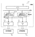
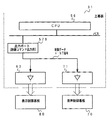
図8は、主基板31におけるCPU56の動作を示すフローチャートである。CPU56は、ROM54に格納されている遊技制御プログラムに従って遊技制御を行う。上述したように、図8に示された処理は、定期リセット回路66が発するリセットパルスによって、例えば2ms毎に起動される。
【0050】
CPU56が起動されると、CPU56は、まず、スタックポインタの指定アドレスをセットするためのスタックセット処理を行う(ステップS1)。次いで、初期化処理を行う(ステップS2)。初期化処理では、CPU56は、RAM55にエラーが含まれているか判定し、エラーが含まれている場合には、RAM55を初期化するなどの処理を行う。
【0051】
次に、表示制御基板80および音声制御基板70に送出される制御コマンドをRAM55の所定の領域に設定する処理を行った後に(制御データ設定処理:ステップS4)、制御コマンドを出力する処理の一部を実行する(制御データ出力処理A:ステップS5A)。制御データ出力処理Aの処理内容については、後で詳述する。
【0052】
次いで、各種出力データの格納領域の内容を各出力ポートに出力する処理を行う(データ出力処理:ステップS6)。また、ホール管理用コンピュータに出力される大当り情報、始動情報、確率変動情報などの出力データを格納領域に設定する出力データ設定処理を行う(ステップS8)。さらに、パチンコ遊技機1の内部に備えられている自己診断機能によって種々の異常診断処理が行われ、その結果に応じて必要ならば警報が発せられる(エラー処理:ステップS9)。
【0053】
次に、遊技制御に用いられる大当り判定用の乱数等の各判定用乱数を示す各カウンタを更新する処理を行う(ステップS10)。図9は、各乱数を示す説明図である。各乱数は、以下のように使用される。
(1)ランダム1:大当りを発生させるか否か決定する(大当り判定用=特別図柄決定用)
(2)ランダム2−1〜2−3:左右中のはずれ図柄決定用
(3)ランダム3:大当り時の図柄の組合せを決定する(大当り図柄決定用=特別図柄判定用)
(4)ランダム4:はずれ時にリーチするか否か決定する(リーチ判定用)
(5)ランダム5:大当り予告を行うか否か決定する(大当り予告用)
(6)ランダム6:リーチパターンを決定する(リーチ用)
【0054】
なお、遊技効果を高めるために、上記(1)〜(6)の乱数以外の乱数も用いられている。
ステップS10では、CPU56は、(1)の大当たり判定用乱数および(3)の大当り図柄判定用乱数を生成するためのカウンタのカウントアップ(1加算)を行う。すなわち、それらが判定用乱数である。
【0055】
次に、CPU56は、特別図柄プロセス処理を行う(ステップS11)。特別図柄プロセス制御では、遊技状態に応じてパチンコ遊技機1を所定の順序で制御するための特別図柄プロセスフラグに従って該当する処理が選び出されて実行される。そして、特別図柄プロセスフラグの値は、遊技状態に応じて各処理中に更新される。
【0056】
ここで、制御コマンドを出力する処理の一部を実行する(制御データ出力処理B:ステップS5B)。制御データ出力処理Bの処理内容については、後で詳述する。
【0057】
また、普通図柄プロセス処理を行う(ステップS12)。普通図柄プロセス処理では、7セグメントLEDによる可変表示器10を所定の順序で制御するための普通図柄プロセスフラグに従って該当する処理が選び出されて実行される。そして、普通図柄プロセスフラグの値は、遊技状態に応じて各処理中に更新される。
【0058】
さらに、CPU56は、スイッチ回路58を介して、ゲートセンサ12、始動口センサ17およびカウントセンサ23の状態を入力し、各入賞口や入賞装置に対する入賞があったか否か判定する(スイッチ処理:ステップS13)。
【0059】
CPU56は、さらに、表示用乱数を更新する処理を行う(ステップS15)。すなわち、ランダム2,4,5,6を生成するためのカウンタのカウントアップ(1加算)を行う。
【0060】
また、CPU56は、賞球制御基板37との間の信号処理を行う(ステップS16)。すなわち、所定の条件が成立すると賞球制御基板37に賞球制御コマンドを出力する。賞球制御基板37に搭載されている賞球制御用CPUは、賞球制御コマンドに応じて玉払出装置97を駆動する。
【0061】
ここで、制御コマンドを出力する処理の一部を実行する(制御データ出力処理B:ステップS5C)。制御データ出力処理Cの処理内容については、後で詳述する。
その後、CPU56は、次に定期リセット回路66からリセットパルスが与えられるまで、ステップS17の表示用乱数更新処理を繰り返す。
【0062】
次に、始動入賞口14への入賞にもとづいて可変表示部9に可変表示される図柄の決定方法について図10〜図12のフローチャートを参照して説明する。図10は打球が始動入賞口14に入賞したことを判定する処理を示し、図11は可変表示部9の可変表示の停止図柄を決定する処理を示す。図12は、大当りとするか否かを決定する処理を示すフローチャートである。
【0063】
打球が遊技盤6に設けられている始動入賞口14に入賞すると、始動口センサ17がオンする。CPU56は、メイン処理のステップS11の特別図柄プロセス処理において、スイッチ回路58を介して始動口センサ17がオンしたことを判定すると(ステップS41)、始動入賞記憶数が最大値である4に達しているかどうか確認する(ステップS42)。始動入賞記憶数が4に達していなければ、始動入賞記憶数を1増やし(ステップS43)、大当り判定用乱数の値を抽出する。そして、それを始動入賞記憶数の値に対応した乱数値格納エリアに格納する(ステップS44)。なお、始動入賞記憶数が4に達している場合には、始動入賞記憶数を増やす処理を行わない。すなわち、この実施の形態では、最大4個の始動入賞口14に入賞した打球数が記憶可能である。
【0064】
図柄の変動を開始できる状態になると、CPU56は、図11に示すように、始動入賞記憶数の値を確認する(ステップS50)。始動入賞記憶数が0でなければ、始動入賞記憶数=1に対応する乱数値格納エリアに格納されている値を読み出すとともに(ステップS51)、始動入賞記憶数の値を1減らし、かつ、各乱数値格納エリアの値をシフトする(ステップS52)。すなわち、始動入賞記憶数=n(n=2,3,4)に対応する乱数値格納エリアに格納されている値を、始動入賞記憶数=n−1に対応する乱数値格納エリアに格納する。
【0065】
そして、CPU56は、ステップS51で読み出した値、すなわち抽出されている大当り判定用乱数の値にもとづいて当たり/はずれを決定する(ステップS53)。ここでは、大当り判定用乱数は0〜299の範囲の値をとることにする。図12に示すように、低確率時には例えばその値が「3」である場合に「大当り」と決定し、それ以外の値である場合には「はずれ」と決定する。高確率時には例えばその値が「3」,「7」,「79」,「103」,「107」のいずれかである場合に「大当り」と決定し、それ以外の値である場合には「はずれ」と決定する。
【0066】
大当たりと判定されたときには、CPU56は、大当り予告を行うか否か決定する。すなわち、大当り予告用乱数(ランダム5)の値を抽出し、その値が0または1ならば大当り予告を行うことに決定する(ステップS65)。また、リーチ用乱数(ランダム6)を抽出しその値にもとづいてリーチ種類を決定する(ステップS57)。
【0067】
はずれと判定された場合には、CPU56は、リーチとするか否か判定する(ステップS58)。例えば、リーチ判定用の乱数であるランダム4の値が「105」〜「1530」のいずれかである場合には、リーチとしないと決定する。そして、リーチ判定用乱数の値が「0」〜「104」のいずれかである場合にはリーチとすることを決定する。リーチとすることを決定したときには、CPU56は、リーチ図柄の決定を行う。
【0068】
この実施の形態では、ランダム2−1の値に従って左右図柄を決定する(ステップS59)。また、ランダム2−2の値に従って中図柄を決定する(ステップS60)。すなわち、ランダム2−1およびランダム2−2の値の0〜11の値に対応したいずれかの図柄が停止図柄として決定される。ここで、決定された中図柄が左右図柄と一致した場合には、中図柄に対応した乱数の値に1加算した値に対応する図柄を中図柄の確定図柄として、大当たり図柄と一致しないようにする。
【0069】
さらに、CPU56は、大当り予告用乱数(ランダム5)の値を抽出し、その値が0ならば大当り予告を行うことに決定する(ステップS66)。また、リーチ用乱数(ランダム6)を抽出しその値にもとづいてリーチ種類を決定する(ステップS57)。
【0070】
ステップS58において、リーチしないことに決定された場合には、ランダム2−1〜2−3の値に応じて左右中図柄を決定する(ステップS61)。なお、後述するように、この実施の形態では、高確率状態では、はずれ時の変動パターンとして変動時間が短縮されたものも使用される。そこで、高確率状態では、CPU56は、通常のはずれ時の変動パターンを用いるか短縮された変動パターンを用いるのかを、例えば所定の乱数等を用いて決定する。
【0071】
以上のようにして、始動入賞にもとづく図柄変動の表示態様が大当たりとするか、リーチ態様とするか、はずれとするか決定され、それぞれの停止図柄の組合せが決定される。
【0072】
なお、高確率状態において、次に大当たりとなる確率が上昇するとともに、7セグメントLEDによる可変表示器10の可変表示の確定までの時間が短縮され、かつ、可変表示器10の可変表示結果にもとづく当たり時の可変入賞球装置15の開放回数および開放時間が高められるようにパチンコ遊技機1が構成されていてもよいし、可変表示器10の可変表示結果にもとづく当たりの確率が高くなるように構成されていてもよい。また、それらのうちのいずれか一つまたは複数の状態のみが生ずるパチンコ遊技機1においても本発明は適用可能である。
【0073】
例えば、可変表示部9の停止図柄の組合せが特定図柄となった場合に、大当たりとなる確率は上昇しないが可変表示器10の可変表示結果にもとづく当たり時の可変入賞球装置15の開放回数および開放時間が高められる遊技機においても、リーチとすることが決定されたら、左右の停止図柄を特定図柄の表示態様と一致させるか否か、すなわちどの図柄でリーチ状態を発生させるかが所定の乱数等の手段によって決定される遊技機においても本発明を適用可能である。
また、この実施の形態で用いられた乱数および乱数値の範囲は一例であって、どのような乱数を用いてもよいし、範囲設定も任意である。
【0074】
上述したように、始動入賞口14に打球が入賞すると、CPU56は、ステップS11(図9参照)の特別図柄プロセス処理において、大当たりとするかはずれとするかと、停止図柄とを決定するが、その決定に応じた制御コマンドを表示制御基板80の表示制御用CPU101に与える。表示制御用CPU101は、主基板31からの制御コマンドに応じて可変表示部9の表示制御を行う。
【0075】
図13は基本回路53における特別図柄プロセス処理のプログラムの一例を示すフローチャートである。図13に示す特別図柄プロセス処理は、図8のフローチャートにおけるステップS11の具体的な処理である。基本回路53のCPU56は、特別図柄プロセス処理を行う際に、その内部状態に応じて、図13に示すステップS300〜S309のうちのいずれかの処理を行う。各処理において、以下のような処理が実行される。
【0076】
特別図柄変動待ち処理(ステップS300):始動入賞口14(この実施の形態では可変入賞球装置15の入賞口)に打球入賞して始動口センサ17がオンするのを待つ。始動口センサ17がオンすると、始動入賞記憶数が満タンでなければ、始動入賞記憶数を+1するとともに大当り判定用乱数を抽出する。すなわち、図10に示された処理が実行される。
特別図柄判定処理(ステップS301):特別図柄の可変表示が開始できる状態になると、始動入賞記憶数を確認する。始動入賞記憶数が0でなければ、抽出されている大当り判定用乱数の値に応じて大当たりとするかはずれとするか決定する。すなわち、図11に示された処理の前半が実行される。
停止図柄設定処理(ステップS302):左右中図柄の停止図柄を決定する。すなわち、図11に示された処理の中半が実行される。
【0077】
リーチ動作設定処理(ステップS303):リーチ判定用乱数の値に応じてリーチ動作するか否か決定するとともに、リーチ動作用乱数の値に応じてリーチ動作の変動態様を決定する。すなわち、図11に示された処理の後半が実行される。
【0078】
全図柄変動開始処理(ステップS304):可変表示部9において全図柄が変動開始されるように制御する。このとき、表示制御基板80に対して、左右中最終停止図柄と変動態様を指令する情報とが送信される。また、可変表示部9に背景やキャラクタも表示される場合には、それに応じた制御コマンドが表示制御基板80に送出されるように制御する。
【0079】
全図柄停止待ち処理(ステップS305):所定時間が経過すると、可変表示部9において表示される全図柄が停止されるように制御する。
【0080】
大当たり表示処理(ステップS306):停止図柄が大当たり図柄の組み合わせである場合には、大当たり表示の制御コマンドが表示制御基板80に送出されるように制御するとともに内部状態(プロセスフラグ)をステップS307に移行するように更新する。そうでない場合には、内部状態をステップS309に移行するように更新する。なお、大当たり図柄の組み合わせは、左右中図柄が揃った組み合わせである。また、表示制御基板80の表示制御用CPU101は制御コマンドに従って、可変表示部9に大当り表示を行う。大当り表示は遊技者に大当りの発生を報知するためになされるものである。
大入賞口開放開始処理(ステップS307):大入賞口を開放する制御を開始する。具体的には、カウンタやフラグを初期化するとともに、ソレノイド21を駆動して大入賞口を開放する。
【0081】
大入賞口開放中処理(ステップS308):大入賞口ラウンド表示の制御コマンドが表示制御基板80に送出する制御や大入賞口の閉成条件の成立を確認する処理等を行う。大入賞口の閉成条件が成立したら、大当り遊技状態の終了条件が成立していなければ内部状態をステップS307に移行するように更新する。大当り遊技状態の終了条件が成立していれば、内部状態をステップS309に移行するように更新する。
【0082】
大当たり終了処理(ステップS309):大当たり遊技状態が終了したことを遊技者に報知するための表示を行う。その表示が終了したら、内部フラグ等を初期状態に戻し、内部状態をステップS300に移行するように更新する。
【0083】
上記の各ステップの処理に応じて、遊技制御プログラム中の制御コマンドを送出する処理を行うモジュール(図8におけるステップS5A,5B,5C)は、対応する制御コマンドを出力ポート571,575に出力するとともに、ストローブ信号(INT信号)を出力する。
【0084】
図14は、特別図柄プロセス処理において用いられるプロセスデータのデータ構成を示す説明図である。プロセスデータは、基本回路53のROM54に格納されている。そして、特別図柄プロセス処理における各プロセス(ステップS300〜S309)は、プロセスデータに設定されている各データに応じて、図柄変動制御、ランプ・LED制御および音声制御を行う。すなわち、各プロセス(ステップS300〜S309)に応じたプロセスデータがROM55に格納されている。
【0085】
プロセスデータは、4バイトで構成されるデータグループが1つ以上集まったものである。4バイトで構成されるデータグループの1バイト目および2バイト目には、プロセスタイマ値が設定される。3バイト目および4バイト目には、制御コマンドデータが設定される。また、プロセスデータの最後には、プロセスの終了を示す終了コードが付加されている。プロセスデータは、プロセスタイマがタイムアウトすると、特別図柄制御データに対応する制御コマンドがCPU56から表示制御基板80に出力されるように構成されている。従って、各プロセスタイマ値は、制御コマンド送出タイミングを決める。
【0086】
また、この実施の形態では、表示制御基板80に送出される制御コマンドと同じ制御コマンドが、表示制御基板80に送出されるタイミングと同一のタイミングで、音声制御基板70にも送出される。従って、プロセステーブル中の3バイト目および4バイト目は、表示制御基板80および音声制御基板70に送出される制御コマンドを示すデータである。
【0087】
図15は、主基板31から表示制御基板80および音声制御基板70に送信される制御コマンドを示す説明図である。図15に示すように、この実施の形態では、制御コマンドは、制御データCD0〜CD7の8本のデータ線で主基板31から表示制御基板80および音声制御基板70に送信される。また、主基板31と表示制御基板80および音声制御基板70との間には、INT信号を送信するためのINT信号の信号線も配線されている。
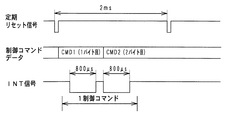
【0088】
図16は、主基板31から表示制御基板80および音声制御基板70に与えられる制御コマンドの送出タイミングを示すタイミング図である。図16に示すように、この実施の形態では、1つの制御コマンドは2バイトで構成され、定期リセット信号の発生間隔(2ms)において1つの制御コマンドが送出される。制御コマンドの各バイトが出力されてから例えば800μs間INT信号がオン状態(ローレベル)になる。表示制御用CPU101および音声制御用CPU701は、INT信号がオンしたことを検出すると、制御コマンドを取り込む処理を行う。
【0089】
この実施の形態では、制御コマンドは2バイト構成であるから、1つの制御コマンドが出力される際に、2回INT信号が出力される。なお、制御コマンドは2バイト構成に限られず、情報量に応じて2バイト以上であってもよい。
【0090】
図17は、図8に示されたメイン処理における制御データ出力処理A(ステップS5A)を示すフローチャートである。制御データ出力処理Aにおいて、CPU56は、ポート出力要求がセットされているか否か判定する(ステップS421)。ポート出力要求がセットされている場合には、ポート出力要求をリセットし(ステップS422)、ポート格納領域の内容(制御コマンドの1バイト目)を出力ポート571,575に出力する(ステップS423)。
【0091】
そして、INT信号をローレベル(オン状態)にし(ステップS424)、800μsタイマをスタートさせて(ステップS425)、データ送出中フラグをオンする(ステップS426)。なお、ポート出力要求は、図8に示されたメイン処理における制御データ設定処理(ステップS4)でセットされる。
【0092】
図18は、図8に示されたメイン処理における制御データ出力処理B(ステップS5B)を示すフローチャートである。制御データ出力処理Bにおいて、CPU56は、まず、データ送出中フラグがオンしているか否か確認する(ステップS431)。オンしていれば、制御データ出力処理Aでセットされている800μsタイマがタイムアウトするのを待つ(ステップS432)。
【0093】
800μsタイマがタイムアウトしたら、INT信号をハイレベル(オフ状態)にし(ステップS433)、所定期間のディレイタイムをおいて(ステップS434)、ポート格納領域の内容(制御コマンドの2バイト目)を出力ポート571,575に出力する(ステップS435)。なお、ディレイタイムは、図16に示されたINT信号の出力タイミングにおける1回目のINT信号のオン期間と2回目のINT信号のオン期間との間のオフ期間を作成するための時間である。
【0094】
そして、INT信号をローレベル(オン状態)にし(ステップS424)、800μsタイマをスタートさせる(ステップS425)。
【0095】
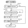
図19は、図8に示されたメイン処理における制御データ出力処理C(ステップS5C)を示すフローチャートである。制御データ出力処理Cにおいて、CPU56は、まず、データ送出中フラグがオンしているか否か確認する(ステップS441)。オンしていれば、制御データ出力処理Bでセットされている800μsタイマがタイムアウトするのを待つ(ステップS442)。
【0096】
800μsタイマがタイムアウトしたら、INT信号をハイレベル(オフ状態)にし(ステップS443)、データ送出中フラグをオフする(ステップS444)。
以上のようにして、図16に示されたようなタイミングで、制御コマンドが表示制御基板80および音声制御基板70に送出される。
【0097】
なお、図8に示されたように、メイン処理の随所で制御データ出力処理A,B,Cを実行する方法は一例であって、他の方法を用いてもよい。例えば、800μsタイマ割り込みによってINT信号のオン/オフ制御を行ってもよい。いずれにせよ、図16に示されたようなタイミングで同一の制御コマンドが主基板31から表示制御基板80および音声制御基板70に送出されればよい。なお、INT信号のオン期間である800μsも一例であって、機種に応じて任意に設定することができる。
【0098】
次に、図柄の変動を具体例を用いて説明する。
図20(A)は、可変表示部9に表示される背景の一例(道場)を示す説明図である。また、図20(B)は、可変表示部9に表示されるキャラクタの一例(男の子)を示す説明図である。なお、背景およびキャラクタは複数種類あるが、図20には、それぞれ1つずつが例示されている。
【0099】
図21は、この実施の形態で用いられる左右中図柄の例を示す説明図である。図21に示すように、この実施の形態では、左右中図柄として表示される各図柄は、左右中で同一の12図柄である。また、図柄番号12の図柄が表示されると、次に、図柄番号1の図柄が表示される。そして、左右中図柄が、例えば、「一」、「三」、「五」、「七」、「九」または「下駄」で揃って停止すると高確率状態となる。すなわち、それらが確変図柄となる。
【0100】
図22〜図26は、この実施の形態で用いられる主基板31から表示制御基板80に送信される制御コマンドの構成例を示す説明図である。上述したように、1つの制御コマンドは2バイト(CMD1,CMD2)で構成される。また、図22〜図26には、各制御コマンドと可変表示部9の表示内容との対応が示されているが、図22〜図26に示された各制御コマンドは、音声制御基板70ランプ制御基板35にも送信される。音声制御は表示制御と同期しているので、表示制御のための制御コマンドを音声制御手段に供給しても、音声制御手段は音声制御を実行することができる。
【0101】
この実施の形態では、遊技制御手段は、図柄の変動開始時に変動パターンと左右中停止図柄とを示す制御コマンドを送出し、図柄の最終停止時に全図柄停止を示す制御コマンドを送出する。表示制御手段は、変動パターンを示す制御コマンドを受信すると、その変動パターンについてあらかじめ決められている各変動態様(低速、中速、高速など)で図柄が可変表示されるように表示制御を行う。
【0102】
また、この実施の形態では、図柄変動中のあらかじめ決められているタイミングで、遊技制御手段は、キャラクタの登場および変更に関する制御コマンドを送出する。音声制御手段は、図柄の変動開始時の変動パターンを示す制御コマンドおよびキャラクタに関する制御コマンドを受信すると、効果音パターンを切り替える。
【0103】
すなわち、以下に述べる例では、効果音パターンの切り替えは背景切替およびキャラクタの動きに同期したものとする。切替およびキャラクタの動きとは無関係に効果音パターンの切り替えを行うタイミングが存在するような場合には、そのようなタイミングでも遊技制御手段から制御コマンドが音声制御基板に対して送出される必要があるが、そのような場合には、図22〜図26に示された制御コマンドに対してコマンドを追加し、1変動中に遊技制御手段から送出される制御コマンド数を、以下に述べる例よりも増やせばよい。
【0104】
つまり、切替およびキャラクタの動きとは無関係に効果音パターンの切り替えを行うタイミングが存在するような場合でも、以下に述べる例に対して制御コマンド数および制御コマンド送出タイミングを拡張するだけでよい。
【0105】
また、表示制御手段は、遊技制御手段から送出された制御コマンドのうち、必要な制御コマンドのみを使用して、不必要なタイミングで受信した制御コマンドを破棄すればよい。例えば、変動パターンに応じてその変動中の切替およびキャラクタの動きはあらかじめ決められているので、遊技制御手段からの切替およびキャラクタに関する制御コマンドを破棄して独自にキャラクタ表示制御を行ってもよい。また、切替およびキャラクタの動きとは無関係に効果音パターンの切り替えを行うタイミングが存在するような場合に、そのようなタイミングで遊技制御手段から送出される制御コマンドを破棄すればよい。
【0106】
表示制御手段および音声制御手段が不要な制御コマンドを破棄するように構成されている場合には、遊技制御手段が、同一の制御コマンドを表示制御手段および音声制御手段に送出しても、表示制御手段および音声制御手段は、決められた表示制御および音声制御を遂行できる。また、遊技制御手段の制御コマンド送出に関する制御が簡略化される。
【0107】
以下、各制御コマンドについて簡単に説明するが、主として表示制御に対応させて説明する。
図22には、全図柄変動開始コマンドと左右中図柄の変動停止を指定するコマンドが示されている。図22に示すように、2バイトの制御データCMD1,CMD2で構成される制御コマンドによって、それらの指定が実現される。なお、それらの指定において、1バイト目の制御データCMD1の値は、「80(H)」である。
【0108】
図23には、左図柄に関する図柄の停止を指示する制御コマンドが示されている。図23に示すように、2バイトの制御データCMD1,CMD2で構成される制御コマンドによって停止図柄が指定される。なお、それらの指定において、1バイト目の制御データCMD1の値は、「8B(H)」である。
【0109】
図24には、中図柄に関する図柄の停止を指示する制御コマンドが示されている。図24に示すように、2バイトの制御データCMD1,CMD2で構成される制御コマンドによって停止図柄が指定される。なお、それらの指定において、1バイト目の制御データCMD1の値は、「8C(H)」である。
【0110】
図25には、右図柄に関する図柄の停止を指示する制御コマンドが示されている。図25に示すように、2バイトの制御データCMD1,CMD2で構成される制御コマンドによって停止図柄が指定される。なお、それらの指定において、1バイト目の制御データCMD1の値は、「8D(H)」である。
【0111】
図26には、背景およびキャラクタに関する制御コマンドの一例が示されている。図26に示すように、2バイトの制御データCMD1,CMD2で構成される制御コマンドによって、背景およびキャラクタが指定される。それらの指定において、1バイト目の制御データCMD1の値は、「C0(H)」である。
【0112】
なお、上述したように、背景およびキャラクタとして複数種類あるので、図26に例示されたもの以外にも、背景およびキャラクタに関する制御コマンドが多数定義されている。また、上述したように、背景およびキャラクタに関する制御コマンドは、この実施の形態では、主として効果音パターン切り替えのために使用される。
【0113】
次に、図27〜図31を参照して図柄の変動パターンの例について説明する。図27は、各変動パターンを構成する変動態様(パターンa〜e)を示す説明図である。図28は、リーチとしないはずれ時の図柄の変動の一例を示すタイミング図である。また、図29〜図31は、リーチ時(大当りの場合および大当りとしない場合)の図柄の変動の一例を示すタイミング図である。
【0114】
この実施の形態では、はずれ時には、図28(A)に示すように、可変表示部9における「左」の図柄表示エリアにおいて、まず、パターンaに従って図柄の変動が行われる。パターンaは、図27に示すように、少しずつ変動速度が上がるパターンである。その後、パターンbの一定速の高速変動が行われ、停止図柄の3図柄前の図柄が表示されるように制御された後、パターンcに従って3図柄の変動が行われる。パターンcは、図27に示すように、徐々に遅くなって停止するパターンである。
【0115】
また、可変表示部9における「右」の図柄表示エリアにおいて、パターンaに従って図柄の変動が行われる。その後、一定速変動の後、停止図柄の3図柄前の図柄が表示されるように制御された後、パターンcに従って図柄の変動が行われる。「中」の図柄表示エリアにおいても、まず、パターンaに従って図柄の変動が行われる。その後、一定速変動の後、停止図柄の3図柄前の図柄が表示されるように制御された後、パターンcに従って図柄の変動が行われる。
【0116】
なお、表示制御基板80の表示制御用CPU101は、中図柄が確定するまで、左右図柄を変動方向の正方向と逆方向に繰り返し変動させる。すなわち、左右図柄を、いわゆる揺れ変動による停止状態に表示制御する。揺れ変動とは、図柄が上下に揺れる表示されることをいう。また、揺れ変動は、最終停止図柄(確定図柄)が表示されるまで行われる。従って、遊技者は、左右中図柄が最終停止するまで各図柄がまだ確定していないこと、すなわち、大当りの対象となる各図柄によって大当りが生ずる可能性があることを左右中図柄が最終停止するまで期待することができる。なお、揺れ停止状態における揺れ変動は、図柄が上下に揺れるだけでなく、左右に揺れたりその他の方向に揺れるように制御されてもよい。
【0117】
そして、主基板31から全図柄停止を指示する表示制御コマンドを受信すると、左右図柄の揺れ変動状態を終了させて左右中図柄が動かない確定状態になる。なお、中図柄も、パターンcによる変動の後に揺れ動作を行い、その後確定状態になるようにしてもよい。
【0118】
表示制御用CPU101は、左右中の図柄表示エリアにおいて、指定された停止図柄で図柄変動が停止するように、所定のタイミングで停止図柄の3図柄前の図柄を表示制御する。変動開始時に左右中の停止図柄が通知され、かつ、はずれ時の変動パターンはあらかじめ決められているので、表示制御用CPU101は、パターンaからパターンbへの切替タイミングおよびパターンbからパターンcへの切替タイミングを認識することができるとともに、差し替えるべき3図柄前の図柄も決定できる。決定された差し替え図柄はVDP103に通知され、VDP103は、そのときに表示している図柄に関係なく、通知された図柄を表示する。
【0119】
図28(B)は、確率変動状態におけるはずれ時の変動パターンの一例を示す。この変動パターンでは、図に示されるように、パターンa、パターンbおよびパターンcに従って左右中図柄の変動が行われた後に、左右中図柄が同時に停止する。
【0120】
図29は、主基板31から変動時間として14.5秒(リーチ短期間)が通知されたときに表示される変動パターンの例を示す。表示制御用CPU101は、リーチ短期間が通知されると、図29に示す変動パターンで左右中図柄が変動するような表示制御を行う。
【0121】
図29に示された変動パターンでは、左右図柄が停止した後パターンdで中図柄の変動が行われる。パターンdは、変動速度が徐々に低下し、その後一定速度で変動が行われるパターンである。そして、リーチ動作に入り、パターンa、パターンbおよびパターンcに従って中図柄の変動が行われる。主基板31から全図柄停止を指示する表示制御コマンドを受信すると、左右図柄の揺れ変動状態を終了させて左右中図柄が動かない確定状態になる。
【0122】
また、表示制御用CPU101は、主基板31から通知されている停止図柄で図柄が確定するように、リーチ動作開始前に図柄の差し替え(図柄の飛ばし制御)を行う。変動パターンはあらかじめ決められているので、表示制御用CPU101は、パターンd〜パターンaへの切替タイミング、パターンdからパターンbへの切替タイミングおよびパターンbからパターンcへの各切替タイミングを認識することができるとともに、すなわち、各変動態様の時間配分を認識できるとともに、差し替えるべき3図柄前の図柄も決定できる。
【0123】
図29に示された変動時間14.5秒の変動パターンでも、表示制御用CPU101は、中図柄が確定するまで、左右図柄を上下に揺れ動作させる。また、中図柄の図柄差し替え制御は、右図柄が停止するタイミングで実行される。表示制御用CPU101は、変動開始時に主基板31から通知されている中停止図柄と、リーチ変動期間(例えば図29におけるパターンd、パターンa、パターンbおよびパターンcの変動期間)における図柄の変動数とに応じて、差し替え図柄を決定する。
【0124】
図30は、主基板31から変動時間として22.5秒(リーチ中期間)が通知されたときに表示される変動パターンの例を示す。表示制御用CPU101は、リーチ中期間が通知されると、図30に示す変動パターンで左右中図柄が変動するような表示制御を行う。
【0125】
図30に示された変動パターンでは、左右図柄が停止した後パターンdの中図柄の変動が行われる。そして、リーチ動作に入り、パターンa、パターンbおよびパターンcに従って中図柄の変動が行われる。主基板31から全図柄停止を指示する表示制御コマンドを受信すると、左右図柄の揺れ変動状態を終了させて左右中図柄が動かない確定状態になる。また、表示制御用CPU101は、主基板31から通知されている停止図柄で図柄が確定するように、リーチ動作開始前に図柄の差し替えを行う。
【0126】
図30に示された変動時間22.5秒の変動パターンでも、表示制御用CPU101は、中図柄が確定するまで、左右図柄を上下に揺れ動作させる。また、中図柄の図柄飛ばし制御は、右図柄が停止するタイミングで実行される。
【0127】
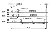
図31は、主基板31から変動時間として29.5秒(リーチ長期間)が通知されたときに表示される変動パターンの例を示す。表示制御用CPU101は、リーチ長期間が通知されると、図31に示す変動パターンで左右中図柄が変動するような表示制御を行う。
【0128】
図31に示された変動パターンでは、左右図柄が停止した後、パターンdに従って中図柄の変動が行われる。その後、パターンeに従って中図柄の変動が行われる。パターンeはコマ送りのパターンである。また、表示制御用CPU101は、主基板31から通知されている停止図柄で図柄が確定するように、リーチ動作開始前に図柄の差し替えを行う。
【0129】
図31に示された変動時間29.5秒の変動パターンでも、表示制御用CPU101は、中図柄が確定するまで、左右図柄を上下に揺れ動作させる。また、中図柄の図柄飛ばし制御は、右図柄が停止するタイミングで実行される。
【0130】
図32は、図28(A)に示されたはずれ時の左右中図柄の変動および背景・キャラクタの表示とその表示に対応する音声制御を実現するため制御切替タイミングを示すタイミング図である。図32に示された例では、表示制御用CPU101は、図柄の変動開始から終了までに、(1)〜(26)の表示制御切替を行う。なお、図32において、黒点は、表示制御用CPU101による変動態様の切替制御タイミングと、音声制御用CPU701の効果音パターン切替タイミングを示している。
【0131】
上述したように、表示制御用CPU101は、主基板31のCPU56から変動パターンを示す制御コマンド(図32に示す例では、はずれ変動を示す制御コマンドA0)を受信したら、受信した変動パターンを構成する各変動態様(低速、中速、高速等)の切替タイミングを決定する。変動パターンを構成する各変動態様の切替タイミングは、あらかじめROMにテーブル等の形式で格納されている。よって、表示制御用CPU101は、受信した制御コマンドに応じて容易に各変動態様の切替タイミング、すなわち各変動態様の時間配分を決定できる。
【0132】
一方、主基板31の基本回路53のROM54にも、例えば同様のテーブル等が格納されている。つまり、図32の例について説明すると、各時間配分を特定できるような情報が格納されている。主基板31のCPU56は、特別図柄プロセス処理における全図柄停止待ち処理(ステップS305:図13参照)において、各配分時間の経過を監視する。そして、図32に示す例では、(1)の変動開始のタイミングの他に、(12),(17),(22),(24)のタイミングになると、制御コマンドを送出する。
【0133】
各制御コマンドは、表示制御基板80および音声制御基板80に送信される。なお、(24)のタイミングで送信される制御コマンドは、全図柄停止を示す制御コマンドである。この実施の形態では、(12),(17),(22)のタイミングで送出される制御コマンドは、表示制御用CPU101で不要である。表示制御用CPU101は、変動開始時に変動パターンを示す制御コマンドを受信すると、その変動パターンを構成する各変動態様の時間配分を独自に決定するからである。よって、表示制御用CPU101は、(12),(17),(22)のタイミングで送出される制御コマンドを入力したら破棄する。
【0134】
図33は、図32に示された例において、背景およびキャラクタの変化を含む各変動態様と、主基板31から表示制御基板80および音声制御基板70に順次送出される制御コマンドとを示す説明図である。図33における(1)〜(26)は、図32における(1)〜(26)のタイミングに対応している。また、図33において、黒星印は音声制御用CPU701が使用する制御コマンドを示す。なお、図33では、停止図柄を示す制御コマンドは記載省略されている。音声制御用CPU701は、各制御コマンドに対応して記憶されている効果音パターンを用いて音発生制御を行う。
【0135】
この実施の形態では、主基板31のCPU56は、図33において黒星印が付されたタイミングにおいて制御コマンドを送出すればよい。ただし、他の背景およびキャラクタの変化を示す制御コマンド(例えば、(2),(3)のタイミングで)も送信して、表示制御用CPU101は、受信した背景およびキャラクタに関する制御コマンドにもとづいて背景およびキャラクタの表示変化を制御してもよい。
【0136】
図34は、図31に示されたリーチ動作時にコマ送り変動が行われるとき(リーチ長期間による変動が行われるとき)の左右中図柄の変動および背景・キャラクタの表示とその表示に対応する音声制御を実現するため制御切替タイミングを示すタイミング図である。図34に示された例では、表示制御用CPU101は、図柄の変動開始から終了までに、(1)〜(32)の表示制御切替を行う。なお、図34において、黒点は、表示制御用CPU101による変動態様の切替制御タイミングと、音声制御用CPU701の効果音パターン切替タイミングを示している。
【0137】
表示制御用CPU101は、主基板31のCPU56からリーチ長期間を示す変動パターンを示す制御コマンドを受信したら、その変動パターンを構成する各変動態様(低速、中速、高速等)の切替タイミングを決定する。変動パターンを構成する各変動態様の切替タイミングは、あらかじめROMにテーブル等の形式で格納されている。
【0138】
主基板31の基本回路53のROM54にも、同様のテーブル等が格納されている。主基板31のCPU56は、特別図柄プロセス処理における全図柄停止待ち処理(ステップS305)において、各配分時間の経過を監視する。そして、(1)の変動開始のタイミングの他に、(12),(17),(21),(27),(29),(30)のタイミングになると、制御コマンドを送出する。
【0139】
各制御コマンドは、表示制御基板80および音声制御基板80に送信される。なお、(30)のタイミングで送信される制御コマンドは、全図柄停止を示す制御コマンドである。この実施の形態では、(12),(17),(21),(27),(29)のタイミングで送出される制御コマンドは、表示制御用CPU101で不要である。よって、表示制御用CPU101は、(12),(17),(21),(27),(29)のタイミングで送出される制御コマンドを入力したら破棄する。
【0140】
図35は、図34に示された例において、背景およびキャラクタの変化を含む各変動態様と、主基板31から表示制御基板80および音声制御基板70に順次送出される制御コマンドとを示す説明図である。図35における(1)〜(32)は、図34における(1)〜(32)のタイミングに対応している。また、図35において、黒星印は音声制御用CPU701が使用する制御コマンドを示す。なお、図35でも、停止図柄を示す制御コマンドは記載省略されている。
【0141】
音声制御用CPU701は、必要な制御コマンドを受信したら、受信した各制御コマンドに対応して記憶されている効果音パターンを用いて音発生制御を行う。
【0142】
以上のように、この実施の形態では、図柄の変動開始時に変動パターンを示す制御コマンドが1回だけ主基板31側から送出される。従って、表示制御基板80および音声制御基板70において速やかに制御を開始できるとともに、主基板31のCPU56の制御コマンド送出に関する負荷が大きく軽減されている。
【0143】
さらに、表示制御基板80における表示制御用CPU101が受信した変動パターンにもとづいて独自にその変動パターンを構成する変動態様の時間配分を決定するので、主基板31から送出されるコマンド数を低減でき、かつ、主基板31のCPU56の制御コマンド送出に要する負荷を低減することができる。
【0144】
なお、以上に述べた例では、主基板31のCPU56が順次制御コマンドを表示制御基板80および音声制御基板70に送出し、表示制御基板80は、必要なコマンドのみを受け入れて、受け入れた制御コマンドに応じた図柄の可変表示制御を行った。しかし、表示制御基板80が、主基板31から送出された全ての制御コマンドを受け入れて制御を行えるように制御コマンドの体系を設計してもよい。その場合には、表示制御基板80は、制御コマンド選択処理を行わず、無条件に全ての制御コマンドを受け入れることができる。
【0145】
図36は、表示制御基板80における表示制御用CPU101および音声制御基板70における音声制御用CPU701のそれぞれが実行する制御コマンド読込動作を示すフローチャートである。制御コマンド読込処理において、各CPU101,701は、制御コマンドデータの入力に割り当てられている入力ポートから1バイトのデータを読み込む(ステップS121)。次に、INT信号の入力に割り当てられている入力ポートからINT信号の状態を読み取る(ステップS122)。上述したように、INT信号は、主基板31のCPU56が新たな制御コマンドデータを出力したときにローレベルとされる。
【0146】
INT信号がオフしている場合には、通信カウンタをクリアする(ステップS126)。通信カウンタは、INT信号がオンしているときの制御コマンドデータ受信回数をカウントするために用いられる。
【0147】
INT信号がオンしている場合には、受信した制御コマンドデータが直前に(100μs前)受信したコマンドデータと同じか否か確認する(ステップS123)。同じでない場合には、通信カウンタをクリアする(ステップS126)。同じであった場合には、通信カウンタが所定の最大値(MAX)に達しているか否か確認する(ステップS124)。
【0148】
最大値に達していない場合には、通信カウンタの値を+1する(ステップS125)。ここで、最大値とは、制御コマンドデータを確実に受信したと判定する値(この例では3)よりも大きい値であり、例えば、800μs間での受信回数をカウントする等の目的で用いられる。
【0149】
次いで、各CPU101,701は、通信カウンタ後が「3」になったか否か確認する(ステップS127)。「3」になっている場合には、受信したデータが制御コマンドの1バイト目(CMD1)であるのか2バイト目(CMD2)であるのかを確認する(ステップS128)。1バイト目であれば、受信したデータを受信コマンド格納エリア(1バイト目)に格納し(ステップS129)、コマンド受信中フラグをセットする(ステップS130)。そして、受信したデータをワークエリアに格納する(ステップS134)。
【0150】
受信したデータが制御コマンドの2バイト目であれば、受信したデータを受信コマンド格納エリア(2バイト目)に格納し(ステップS131)、コマンド受信中フラグをリセットする(ステップS132)。そして、通信終了フラグをセットする(ステップS133)。また、受信したデータをワークエリアに格納する(ステップS134)。「3」になっていない場合には、通信終了フラグをセットせずに、読み取ったデータをワークエリアに格納する(ステップS134)。なお、ワークエリアに格納されたデータは、次の割込処理において、ステップS123において用いられる。
【0151】
以上の処理によって、主基板31から送出された制御コマンドは、表示制御用CPU101および音声制御用CPU701に読み込まれる。
【0152】
図37は、表示制御基板80における表示制御用CPU101および音声制御用CPU701が主基板31から送信された制御コマンドデータを取り込むタイミングの例を示すタイミング図である。図37(A)に示すように、3回連続して同一の制御コマンドデータを受信すると、各CPU101,701は、受信した制御コマンドデータにもとづく制御処理を実行する。すなわち、図37(A)に示す▲3▼のタイミングで、各制御処理が開始される。
【0153】
このように、各CPU101,701は、所定回(この例では3回)連続して同一コマンドを受信すると正しいコマンドを受信できたと判断するので、主基板31と各基板80,70との間のケーブル上などにおいてノイズがのったとしても、その影響を回避することができる。特に、図6,図7に示されたノイズフィルタ107,706でもとりきれないINT信号のノイズがあったとしても、そのノイズの影響を防止できる。
【0154】
例えば、図37(B)は、▲2▼で示されるタイミングの付近でノイズが生じ、▲2▼のタイミングにおける制御コマンドデータが破壊された場合の例を示す。その場合には、図36に示されたステップS123およびS126の処理で通信カウンタがクリアされる。そして、あらためて▲3▼〜▲5▼の3回連続して同一の制御コマンドデータを取り込めると、各CPU101,701は、正しいコマンドを受信できたと判断する。従って、ケーブル上などにおいて誤りが生じた制御コマンドデータにもとづいて表示制御および音声制御がなされることはない。
【0155】
また、主基板31におけるCPU56は、制御パターンの変化点でのみ、主基板31から出力される制御コマンドを変更する制御を行う。さらに、出力される制御コマンドを変更すると、短い所定期間だけ(この例では800μs)、制御コマンドが変化したことを示す信号(INT信号)を出力する。そして、各CPU101,701は、INT信号期間よりも短い周期で制御コマンドデータをサンプリングする。
【0156】
各CPU101,701は短いINT期間においてのみ制御コマンドデータを取り込み、INT信号がオフしたら制御コマンドデータの取り込みを停止するので、常時データを取り込む場合に比べて、ノイズの影響を低減することができる。例えば、図37(C)に示すように、INT信号にノイズがのって、本来オフ状態であるINT信号がオン状態になってしまったとしても(▲1▼’のタイミング)、ノイズの消滅後にINT信号はオフ状態に復帰し、INT信号オフ状態では各CPU101,701は通信カウンタをクリアして制御コマンドデータを取り込まない。従って、誤った制御コマンドデータを受信してしまうことはない。
【0157】
以上のように、この実施の形態では、複数回連続して同一コマンドを受信できたら正しいコマンドを受信できたと判定することによってノイズの影響を防止し、コマンド受信期間を制御コマンドデータ変更後の短い期間に限定することによって、ノイズの影響をより効果的に防止する。なお、この実施の形態では3回連続して同一コマンドを受信できたら正しいコマンドを受信できたと判定したが、必要に応じて、複数回は2回または4回以上であってもよい。
【0158】
この実施の形態では、INT信号期間を800μsとし、各CPU101,701のコマンド取り込み周期を100μsにするとともに正しいデータを受信できたとする判定回数を「3」にしているので、800μsの期間内に、各CPU101,701が複数回正しい制御コマンドデータを受信したと判定する可能性がある。例えば、図37(D)に示すように、▲1▼〜▲3▼の3回連続して同一データを取り込んで正しい制御コマンドデータを受信できたと判定した後に、基板間でノイズ等によって制御コマンドデータが破壊されたような場合である(▲4▼のタイミング)。そして、各CPU101,701は、あらためて▲5▼〜▲7▼の3回連続して同一データを取り込んで正しい制御コマンドデータを受信できたと判定することがある。
【0159】
そのような場合、800μs内で、▲3▼のタイミングで新たなコマンドにもとづく表示制御または音声制御が開始された後、▲7▼のタイミングであらためて同じ表示制御または音声制御が開始されることになる。しかし、その差の時間はきわめて短いので、遊技者の目や耳で判別できる程度の変化とはならず、遊技演出上問題になることはない。
【0160】
表示制御用CPU101は、図36に示された制御コマンド読込処理において通信終了フラグがセットされると、受信コマンド格納エリアに格納された制御コマンドに応じた図柄の変動および背景・キャラクタの表示切替等の処理を行う。
【0161】
図38は、音声制御用CPU701の処理を示すフローチャートである。音声制御用CPU701は、図36に示された制御コマンド読込処理において通信終了フラグがセットされると、受信コマンド格納エリアに格納されている制御コマンドを読み出し(ステップS151)、その制御コマンドに応じて設けられているテーブルを用いて音発生制御を行うように切り替える(ステップS152)。そして、テーブルの設定内容にもとづいて音発生制御を行う(ステップS153)。なお、制御コマンドを受信していない場合には、テーブルの切り替えを行わない。
【0162】
図39は、音声制御用CPU701が用いるテーブルの一構成例を示す説明図である。テーブルは、音声制御用CPU701の内蔵ROMまたは音声制御基板70に搭載されたROMに設定されている。図39には、コマンド[80,01](図33等参照)を受信したときに用いられるテーブルが例示されている。この例では、テーブルは3バイト構成のデータが複数集まった構成である。各データの1,2バイト目はタイマ値を示す。また、3バイト目は音声合成回路702(図7参照)に与えられるコマンドを示す。
【0163】
音声制御用CPU701は、1,2バイト目に設定されている値をタイマにセットするとともに、3バイト目に設定されている値を音声合成回路702に出力する。そして、タイマがタイムアウトすると、次の3バイトのデータを用いてタイマセットおよびコマンド出力を行う。図39に示されたようなテーブルが、音声制御用CPU701が使用する各制御コマンドに対応して設けられている。
【0164】
以上のように、音声制御用CPU701は、受信した制御コマンドに対応した制御パターンを記憶しているので、主基板31のCPU56が、制御パターンの切り替えタイミングのみを通知するだけで音発生制御が実現される。しかも、主基板31のCPU56は、表示制御基板80および音声制御基板70に全く同じコマンドを送出するので、CPU56の制御コマンド送出のための負荷が軽減される。なお、表示制御基板80および音声制御基板70が全ての制御コマンドを使用する必要がなければ、この実施の形態のように、受信コマンドの選択を行えばよい。
【0165】
図5に示されたように、上記の実施の形態では、主基板31には、表示制御基板80に送出される制御コマンドのための出力ポート571および音声制御基板70に送出される制御コマンドのための出力ポート575が別個に設けられていた。しかし、各基板に全く同一の制御コマンドを送出するのであるから、出力ポートは1つであってもよい。
【0166】
図40は、各基板に送出される制御コマンドが1つの出力ポート576から出力される構成を示すブロック図である。図40に示された例では、各出力バッファ回路63,71の信号通過をイネーブルにするための出力ポート577が設けられている。CPU56は、出力ポート576に制御コマンドを出力するとともに、出力バッファ回路63,71を順次イネーブルにする、よって、表示制御基板80および音声制御基板70に順次制御コマンドが送出される。なお、このような構成でも、各基板に送出される制御コマンドは同一である。
【0167】
図41は、各基板に送出される制御コマンドが1つの出力ポート576から出力される他の構成例を示すブロック図である。図41に示された構成では、CPU56は、出力ポート576に制御コマンドを出力する。すると、出力ポート576に並列接続されている各出力バッファ回路63,71から、制御コマンドが表示制御基板80および音声制御基板70に同時に送出される。
【0168】
上記の各実施の形態では、主基板31の遊技制御手段が遊技進行に応じて表示制御基板80および音声制御基板70に制御コマンドを送信する制御を行う遊技機において、遊技制御手段は、所定の制御変化点において、1回だけ各基板80,70のCPU101,701が受信可能に制御コマンドを送出する。従って、このことからも、遊技制御手段の制御コマンド送出に関する負荷が低減される。
【0169】
なお、上記の実施の形態では、表示制御基板80および音声制御基板70への制御コマンドは、主基板31から各基板に送出されたが、音声制御基板70への制御コマンドは、表示制御基板70を介して供給されるように構成してもよい。その場合、表示制御用CPU101への入力が分岐されて音声制御基板70に送出されるように構成してもよいし、表示制御用CPU101が出力ポートを介して音声制御基板70に制御コマンドを送出してもよい。
【0170】
また、上記の実施の形態では、遊技制御手段は、2ms毎に発生するCPU外部からの定期リセット信号による割り込み処理で遊技制御を行ったが、CPU56内部のタイマ割り込みによって例えば2ms毎に遊技制御プログラムが起動される構成であってもよい。
【0171】
なお、上記の各実施の形態のパチンコ遊技機1は、始動入賞にもとづいて可変表示部9に可変表示される特別図柄の停止図柄が所定の図柄の組み合わせになると所定の遊技価値が遊技者に付与可能になる第1種パチンコ遊技機であったが、始動入賞にもとづいて開放する電動役物の所定領域への入賞があると所定の遊技価値が遊技者に付与可能になる第2種パチンコ遊技機や、始動入賞にもとづいて可変表示される図柄の停止図柄が所定の図柄の組み合わせになると開放する所定の電動役物への入賞があると所定の権利が発生または継続する第3種パチンコ遊技機であっても、本発明を適用できる。
【0172】
【発明の効果】
以上のように、本発明によれば、遊技機を、遊技制御手段とは別体に設けられている表示制御手段が、変動時間を特定しうる制御コマンドを入力するとその変動パターンに含まれる複数の変動態様の各時間配分を認識して認識した時間配分に応じて識別情報の変動制御を行い、遊技制御手段が、決定した変動パターンに含まれる複数の変動態様の各時間配分を認識して認識した時間配分に応じたタイミングで遊技制御手段とは別体に設けられている音声制御手段に制御コマンドを出力するように構成したので、遊技制御手段は識別情報の変動表示制御に関わる時間管理を行わずに済み、表示制御手段等の他の制御手段に対する遊技制御手段の制御負担を軽減することができる効果がある。また、遊技制御手段が、表示制御手段および音声制御手段に全く同一の制御コマンドを出力するので、遊技制御手段は音声制御手段に対する制御コマンド出力制御を共通に実行することができ、遊技制御手段の制御コマンド出力に関わる負荷を低減できる効果がある。
【図面の簡単な説明】
【図1】 パチンコ遊技機を正面からみた正面図である。
【図2】 パチンコ遊技機の内部構造を示す全体背面図である。
【図3】 パチンコ遊技機の遊技盤を背面からみた背面図である。
【図4】 主基板における回路構成の一例を示すブロック図である。
【図5】 主基板における制御コマンド送出部分の一例を示すブロック図である。
【図6】 表示制御基板内の回路構成を示すブロック図である。
【図7】 音声制御基板内の回路構成を示すブロック図である。
【図8】 基本回路のメイン処理を示すフローチャートである。
【図9】 各乱数を示す説明図である。
【図10】 打球が始動入賞口に入賞したことを判定する処理を示すフローチャートである。
【図11】 可変表示の停止図柄を決定する処理およびリーチ種類を決定する処理を示すフローチャートである。
【図12】 大当たり判定の処理を示すフローチャートである。
【図13】 特別図柄プロセス処理を示すフローチャートである。
【図14】 プロセステーブルの構成例を示す説明図である。
【図15】 主基板から各基板に送信される制御コマンドを示す説明図である。
【図16】 制御コマンドの送出タイミングの一例を示すタイミング図である。
【図17】 制御データ出力処理Aを示すフローチャートである。
【図18】 制御データ出力処理Bを示すフローチャートである。
【図19】 制御データ出力処理Cを示すフローチャートである。
【図20】 背景およびキャラクタの一例を示す説明図である。
【図21】 左右中図柄の例と変動順序を示す説明図である。
【図22】 左右中図柄の変動を指示するための制御コマンドを示す説明図である。
【図23】 左図柄の停止図柄を指示するための制御コマンドを示す説明図である。
【図24】 中図柄の停止図柄を指示するための制御コマンドを示す説明図である。
【図25】 右図柄の停止図柄を指示するための制御コマンドを示す説明図である。
【図26】 背景およびキャラクタを指示するための制御コマンドを示す説明図である。
【図27】 図柄の各変動パターンを構成する変動状態を示す説明図である。
【図28】 リーチとしないはずれ時の図柄の変動の一例を示すタイミング図である。
【図29】 リーチ時の図柄の変動の一例を示すタイミング図である。
【図30】 リーチ時の図柄の変動の一例を示すタイミング図である。
【図31】 リーチ時の図柄の変動の一例を示すタイミング図である。
【図32】 はずれ時の変動および背景・キャラクタの表示とその表示に対応する音声制御を実現するため制御切替タイミングを示すタイミング図である。
【図33】 はずれ時の背景およびキャラクタの変化を含む各変動態様と制御コマンドとを示す説明図である。
【図34】 コマ送り変動が行われるときの変動および背景・キャラクタの表示とその表示に対応する音声制御を実現するため制御切替タイミングを示すタイミング図である。
【図35】 コマ送り変動が行われるときの背景およびキャラクタの変化を含む各変動態様と制御コマンドとを示す説明図である。
【図36】 制御コマンド読み込み処理を示すフローチャートである。
【図37】 表示制御用CPUが制御コマンドデータを取り込むタイミングの例を示すタイミング図である。
【図38】 音声制御用CPUの処理を示すフローチャートである。
【図39】 音声制御用CPUが用いるテーブルの一構成例を示す説明図である。
【図40】 各基板に送出される制御コマンドが1つの出力ポートから出力される構成を示すブロック図である。
【図41】 各基板に送出される制御コマンドが1つの出力ポートから出力される他の構成を示すブロック図である。
【符号の説明】
9 可変表示部
31 遊技制御基板(主基板)
53 基本回路
56 CPU
62,63 出力バッファ回路
70 音声制御基板
80 表示制御基板
101 表示制御用CPU
571,575 出力ポート
701 音声制御用CPU[0001]
BACKGROUND OF THE INVENTION
The present invention relates to a gaming machine such as a pachinko gaming machine or a coin gaming machine, and particularly includes a variable display device whose display state can be changed, and a display result in the variable display device becomes a predetermined specific display mode. The present invention relates to a gaming machine that can be given a predetermined gaming value.
[0002]
[Prior art]
As a gaming machine, a variable display device having a variable display unit whose display state can be changed is provided, and a big hit game that is advantageous to the player when the display result of the variable display unit becomes a predetermined specific display mode Some are configured to transition to a state. The variable display device has a plurality of variable display units, and is usually configured to display the display results of the plurality of variable display units at different times. For example, a plurality of pieces of identification information such as symbols are variably displayed on the variable display section. That the display result of the variable display unit is a combination of specific display modes determined in advance is usually referred to as “big hit”. Note that the game value is the right that the state of the variable winning ball device provided in the gaming area of the gaming machine is advantageous for a player who is likely to win a ball, or the advantageous state for a player. It is to generate.
[0003]
When a big hit occurs, for example, the big winning opening is opened a predetermined number of times, and the game shifts to a big hit gaming state in which a hit ball is easy to win. And in each open period, if there is a prize for a predetermined number (for example, 10) of the big prize opening, the big prize opening is closed. And the number of times the special winning opening is opened is fixed to a predetermined number (for example, 16 rounds). An opening time (for example, 29.5 seconds) is determined for each opening, and even if the number of winnings does not reach a predetermined number, the big winning opening is closed when the opening time elapses. In addition, when a predetermined condition (for example, winning in a V zone provided in the big prize opening) is not established at the time when the big prize opening is closed, the big hit game even if the predetermined number of times is not reached The state ends.
[0004]
In addition, among the combinations of “out of” display modes other than the “big hit” combination, the display results are already derived and displayed at a stage where some of the display results of the plurality of variable display portions have not yet been derived and displayed. A state in which the display mode of the variable display unit satisfies a display condition that is a combination of specific display modes is referred to as “reach”. A player plays a game while enjoying how to generate a big hit.
[0005]
The game progress in the gaming machine is controlled by game control means such as a microcomputer. The identification information, character image, and background image displayed on the variable display device are controlled by display control means that operates according to a control command from the game control means. Generally, the display control means is provided on a board different from the board on which the game control means is mounted. Accordingly, the game control means for controlling the progress of the game needs to transmit a display control command to the display control means.
[0006]
In addition, the game board is provided with a speaker, and various sound effects are emitted from the speaker as the game progresses in order to enhance the game effect. The generation of the sound effect is controlled by the game control means or the voice control means for receiving a control command from the game control means.
[0007]
Generally, sound effect pattern switching control is performed by a game control means for controlling the progress of a game. Therefore, when the voice control means is provided on a board different from the board on which the game control means is mounted, the game control means transmits a control command to the voice control means as the game progresses. There is a need.
[0008]
[Problems to be solved by the invention]
Since the conventional gaming machine is configured as described above, it is necessary for the game control means to send a control command to each of the display control means and the voice control means when performing game control. Therefore, there is a problem that the processing time that can be spent for the original game control is limited due to the heavy load required for sending out the control command of the game control means. In particular, the control command must be sent to the display control means while controlling the time distribution of each variation mode in the variation pattern of the identification information, so the load required for display control is large.
[0009]
Therefore, an object of the present invention is to provide a gaming machine that can reduce the control burden of the game control means on other control means such as display control means.
[0010]
[Means for Solving the Problems]
The gaming machine according to the present invention can change the display state.tableA variable display unit having a display area is included, and the identification information displayed in the display area starts to change in response to the establishment of the change start condition, and the display result of the identification information has become a predetermined specific display mode. A gaming machine capable of giving a predetermined game value to a player on condition that the game control means for controlling the progress of the game and the game control means are provided separately from the game control means.Control commandThe display control means for controlling the display of the variable display unit according to the game control means and the game control means are provided separately from the game control means.Control commandVoice control means for performing sound output control according to the display, the game control means is a display content determination means for determining a variation pattern of the identification information, and the variation of the variation pattern determined at least based on the determination of the display content determination means Can specify timeControl commandCommand output means capable of outputting the output, and the display control means can specify the variation timeControl commandTheinputThen, the variation control of the identification information is performed according to the recognized time distribution by recognizing each time distribution of the plurality of variation modes included in the variation pattern, and the game control means includes the plurality of variation modes included in the determined variation pattern The control command is sent to the voice control means at a timing according to the recognized time allocation.Output the same control command to the display control means and the voice control meansConfigured as follows.
[0021]
DETAILED DESCRIPTION OF THE INVENTION
Hereinafter, an embodiment of the present invention will be described with reference to the drawings.
First, the overall configuration of a pachinko gaming machine that is an example of a gaming machine will be described. 1 is a front view of the
[0022]
As shown in FIG. 1, the
[0023]
Near the center of the
[0024]
An open /
[0025]
The
[0026]
The hit ball fired from the hit ball launching device enters the
[0027]
The rotation of the image in the
[0028]
When the combination of images in the
Further, when the stop symbol on the
[0029]
Next, the structure of the back surface of the
On the back surface of the
[0030]
The
[0031]
FIG. 3 is a rear view of the game board of the
[0032]
In order to perform the winning ball payout control, signals from the winning
[0033]
FIG. 4 is a block diagram illustrating an example of a circuit configuration in the
[0034]
Further, according to the data given from the basic circuit 53, the jackpot information indicating the occurrence of the jackpot, the effective starting information indicating the number of starting winning balls used for starting the image display of the
[0035]
The basic circuit 53 includes a
[0036]
Further, an initial reset circuit 65 for resetting the basic circuit 53 when the power is turned on is provided on the
[0037]
A ball hitting device for hitting and launching a game ball is driven by a drive motor 94 controlled by a circuit on the launch control board 91. Then, the driving force of the drive motor 94 is adjusted according to the operation amount of the
[0038]
FIG. 5 is a block diagram showing an example of a control command sending part on the
[0039]
As will be described later, each control command includes control data and an INT signal indicating the output of the control data. Further, the control commands sent to the
[0040]
Here, the outputs of the
[0041]
FIG. 6 is a block diagram showing a circuit configuration in the
[0042]
Then, the display control CPU 101 performs display control of a screen displayed on the CRT 82 in accordance with the received control command. Specifically, a command according to the control command is given to the
[0043]
6 also shows a reset circuit 83 for resetting the
[0044]
The input buffer circuit 105 can pass signals only in the direction from the
[0045]
FIG. 7 is a block diagram illustrating a configuration example of the
[0046]
As shown in FIG. 7, in the
[0047]
The voice control CPU 701 gives a control signal to the
[0048]
The
[0049]
Next, the operation of the gaming machine will be described.
FIG. 8 is a flowchart showing the operation of the CPU 56 in the
[0050]
When the CPU 56 is activated, the CPU 56 first performs a stack setting process for setting the designated address of the stack pointer (step S1). Next, initialization processing is performed (step S2). In the initialization process, the CPU 56 determines whether or not an error is included in the RAM 55. If the error is included, the CPU 56 performs a process such as initializing the RAM 55.
[0051]
Next, after performing a process of setting a control command sent to the
[0052]
Next, a process of outputting the contents of the storage area for various output data to each output port is performed (data output process: step S6). Further, an output data setting process for setting output data such as jackpot information, start information, probability variation information, etc., output to the hall management computer in the storage area is performed (step S8). Further, various abnormality diagnosis processes are performed by the self-diagnosis function provided in the
[0053]
Next, a process of updating each counter indicating each determination random number such as a big hit determination random number used for game control is performed (step S10). FIG. 9 is an explanatory diagram showing each random number. Each random number is used as follows.
(1) Random 1: Decide whether or not to generate a big hit (for big hit determination = special symbol determination)
(2) Random 2-1 to 2-3: For determining the left and right out-of-line symbols
(3) Random 3: The combination of symbols at the time of jackpot is determined (for jackpot symbol determination = special symbol judgment)
(4) Random 4: Decide whether or not to reach when falling off (for reach determination)
(5) Random 5: Decide whether or not to make a jackpot notice (for jackpot notice)
(6) Random 6: Reach pattern is determined (for reach)
[0054]
In order to enhance the game effect, random numbers other than the random numbers (1) to (6) are also used.
In step S10, the CPU 56 counts up (adds 1) a counter for generating the jackpot determination random number (1) and the jackpot symbol determination random number (3). That is, they are determination random numbers.
[0055]
Next, the CPU 56 performs special symbol process processing (step S11). In the special symbol process control, corresponding processing is selected and executed according to a special symbol process flag for controlling the
[0056]
Here, a part of the process of outputting the control command is executed (control data output process B: step S5B). The details of the control data output process B will be described later.
[0057]
Also, normal symbol process processing is performed (step S12). In the normal symbol process, the corresponding process is selected and executed in accordance with the normal symbol process flag for controlling the
[0058]
Further, the CPU 56 inputs the states of the
[0059]
The CPU 56 further performs a process of updating the display random number (step S15). That is, the counter for generating
[0060]
Further, the CPU 56 performs signal processing with the prize ball control board 37 (step S16). That is, when a predetermined condition is satisfied, a prize ball control command is output to the prize
[0061]
Here, a part of the process of outputting the control command is executed (control data output process B: step S5C). The details of the control data output process C will be described later.
Thereafter, the CPU 56 repeats the display random number updating process in step S17 until a reset pulse is next supplied from the periodic reset circuit 66.
[0062]
Next, a method for determining a symbol variably displayed on the
[0063]
When the hit ball wins the
[0064]
When it becomes a state where the change of the symbol can be started, the CPU 56 confirms the value of the start winning memory number as shown in FIG. 11 (step S50). If the starting winning memory number is not 0, the value stored in the random number value storage area corresponding to the starting winning memory number = 1 is read (step S51), the value of the starting winning memory number is decreased by 1, and each The value in the random value storage area is shifted (step S52). That is, the value stored in the random number value storage area corresponding to the starting winning memory number = n (n = 2, 3, 4) is stored in the random number value storing area corresponding to the starting winning memory number = n−1. .
[0065]
Then, the CPU 56 determines the winning / losing based on the value read in step S51, that is, the value of the extracted big hit determination random number (step S53). Here, the jackpot determination random number takes a value in the range of 0-299. As shown in FIG. 12, at the time of low probability, for example, when the value is “3”, it is determined as “big hit”, and when it is any other value, it is determined as “out of”. When the probability is high, for example, when the value is any one of “3”, “7”, “79”, “103”, “107”, “big hit” is determined. It is determined as “out of”.
[0066]
When it is determined that the jackpot is made, the CPU 56 determines whether or not to make a jackpot notice. That is, the value of the random number for jackpot warning (random 5) is extracted, and if the value is 0 or 1, it is decided to perform the jackpot warning (step S65). Further, the reach random number (random 6) is extracted and the reach type is determined based on the value (step S57).
[0067]
If it is determined that there is a loss, the CPU 56 determines whether or not to reach (step S58). For example, when the value of random 4, which is a random number for reach determination, is any one of “105” to “1530”, it is determined not to reach. If the value of the reach determination random number is any one of “0” to “104”, it is determined to reach. When determining to reach, the CPU 56 determines the reach symbol.
[0068]
In this embodiment, the left and right symbols are determined according to the value of random 2-1 (step S59). Further, the medium symbol is determined according to the value of random 2-2 (step S60). That is, any symbol corresponding to the values of 0 to 11 of the random 2-1 and random 2-2 values is determined as the stop symbol. Here, when the determined middle symbol matches the left and right symbols, the symbol corresponding to the value obtained by adding 1 to the random number value corresponding to the middle symbol is set as the determined symbol of the middle symbol so as not to match the jackpot symbol To do.
[0069]
Further, the CPU 56 extracts the value of the random number for jackpot warning (random 5), and determines that the jackpot warning is made if the value is 0 (step S66). Further, the reach random number (random 6) is extracted and the reach type is determined based on the value (step S57).
[0070]
If it is decided not to reach in step S58, the left and right middle symbols are decided according to the random values 2-1 to 2-3 (step S61). As will be described later, in this embodiment, in a high probability state, a variation pattern with a shortened variation time is also used as a variation pattern at the time of loss. Therefore, in the high probability state, the CPU 56 determines whether to use the normal fluctuation pattern or the shortened fluctuation pattern using, for example, a predetermined random number.
[0071]
As described above, it is determined whether the display mode of the symbol variation based on the start winning is a big hit, a reach mode, or a deviation mode, and a combination of each stop symbol is determined.
[0072]
In the high probability state, the probability of the next big hit increases, the time until the variable display of the
[0073]
For example, when the combination of the stop symbols of the
Further, the random number and the range of the random value used in this embodiment are merely examples, and any random number may be used, and the range setting is also arbitrary.
[0074]
As described above, when the hit ball is won at the
[0075]
FIG. 13 is a flowchart showing an example of a special symbol process processing program in the basic circuit 53. The special symbol process shown in FIG. 13 is a specific process of step S11 in the flowchart of FIG. When performing the special symbol process, the CPU 56 of the basic circuit 53 performs any one of steps S300 to S309 shown in FIG. 13 according to the internal state. In each process, the following process is executed.
[0076]
Special symbol variation waiting process (step S300): Waiting for the
Special symbol determination process (step S301): When variable symbol special display can be started, the number of start winning memories is confirmed. If the starting winning memorization number is not 0, it is determined whether to win or not depending on the value of the extracted jackpot determination random number. That is, the first half of the process shown in FIG. 11 is executed.
Stop symbol setting process (step S302): The stop symbol of the middle left and right symbols is determined. That is, the middle half of the process shown in FIG. 11 is executed.
[0077]
Reach operation setting process (step S303): It is determined whether or not a reach operation is performed according to the value of the reach determination random number, and a variation mode of the reach operation is determined according to the value of the reach operation random number. That is, the second half of the process shown in FIG. 11 is executed.
[0078]
All symbol variation start processing (step S304): Control is performed so that the
[0079]
All symbols stop waiting process (step S305): When a predetermined time has elapsed, control is performed so that all symbols displayed on the
[0080]
Jackpot display processing (step S306): If the stop symbol is a combination of jackpot symbols, control is performed so that a jackpot display control command is sent to the
Big winning opening opening process (step S307): Control for opening the big winning opening is started. Specifically, the counter and the flag are initialized, and the
[0081]
Processing for opening a special prize opening (step S308): A control for sending a control command for a big prize opening round display to the
[0082]
Jackpot end process (step S309): A display for notifying the player that the jackpot gaming state has ended is performed. When the display is completed, the internal flag and the like are returned to the initial state, and the internal state is updated to shift to step S300.
[0083]
The modules (steps S5A, 5B, and 5C in FIG. 8) that perform processing for sending out control commands in the game control program according to the processing of each step described above output the corresponding control commands to the
[0084]
FIG. 14 is an explanatory diagram showing a data structure of process data used in the special symbol process. The process data is stored in the
[0085]
The process data is a collection of one or more data groups composed of 4 bytes. A process timer value is set in the first and second bytes of a data group composed of 4 bytes. Control command data is set in the third and fourth bytes. An end code indicating the end of the process is added to the end of the process data. The process data is configured such that when the process timer times out, a control command corresponding to the special symbol control data is output from the CPU 56 to the
[0086]
In this embodiment, the same control command as that sent to the
[0087]
FIG. 15 is an explanatory diagram showing control commands transmitted from the
[0088]
FIG. 16 is a timing chart showing the transmission timing of control commands given from the
[0089]
In this embodiment, since the control command has a 2-byte configuration, the INT signal is output twice when one control command is output. The control command is not limited to a 2-byte configuration, and may be 2 bytes or more according to the amount of information.
[0090]
FIG. 17 is a flowchart showing the control data output process A (step S5A) in the main process shown in FIG. In the control data output process A, the CPU 56 determines whether or not a port output request is set (step S421). If the port output request is set, the port output request is reset (step S422), and the contents of the port storage area (the first byte of the control command) are output to the
[0091]
Then, the INT signal is set to the low level (on state) (step S424), the 800 μs timer is started (step S425), and the data sending flag is turned on (step S426). The port output request is set in the control data setting process (step S4) in the main process shown in FIG.
[0092]
FIG. 18 is a flowchart showing the control data output process B (step S5B) in the main process shown in FIG. In the control data output process B, the CPU 56 first checks whether or not the data sending flag is on (step S431). If it is on, it waits for the 800 μs timer set in the control data output process A to time out (step S432).
[0093]
When the 800 μs timer times out, the INT signal is set to the high level (off state) (step S433), a delay time of a predetermined period is set (step S434), and the contents of the port storage area (second byte of the control command) are output. It outputs to 571,575 (step S435). Note that the delay time is a time for creating an OFF period between the ON period of the first INT signal and the ON period of the second INT signal at the output timing of the INT signal shown in FIG.
[0094]
Then, the INT signal is set to the low level (ON state) (step S424), and the 800 μs timer is started (step S425).
[0095]
FIG. 19 is a flowchart showing the control data output process C (step S5C) in the main process shown in FIG. In the control data output process C, the CPU 56 first checks whether or not the data sending flag is turned on (step S441). If it is on, it waits for the 800 μs timer set in the control data output process B to time out (step S442).
[0096]
When the 800 μs timer times out, the INT signal is set to the high level (off state) (step S443), and the data sending flag is turned off (step S444).
As described above, the control command is sent to the
[0097]
As shown in FIG. 8, the method of executing the control data output processes A, B, and C everywhere in the main process is an example, and other methods may be used. For example, the ON / OFF control of the INT signal may be performed by an 800 μs timer interrupt. In any case, the same control command may be sent from the
[0098]
Next, the variation of symbols will be described using a specific example.
FIG. 20A is an explanatory diagram showing an example (dojo) of the background displayed on the
[0099]
FIG. 21 is an explanatory diagram showing an example of the middle left and right symbols used in this embodiment. As shown in FIG. 21, in this embodiment, the symbols displayed as the left and right middle symbols are the same 12 symbols in the left and right. When the
[0100]
FIG. 22 to FIG. 26 are explanatory diagrams showing configuration examples of control commands transmitted from the
[0101]
In this embodiment, the game control means transmits a control command indicating a variation pattern and a left / right middle stop symbol at the start of symbol variation, and transmits a control command indicating all symbol stops at the final stop of the symbol. When receiving the control command indicating the variation pattern, the display control means performs display control so that the symbols are variably displayed in each variation mode (low speed, medium speed, high speed, etc.) determined in advance for the variation pattern.
[0102]
In this embodiment, the game control means sends a control command relating to the appearance and change of a character at a predetermined timing during symbol variation. When the voice control means receives a control command indicating a variation pattern at the start of symbol variation and a control command related to the character, the voice control means switches the sound effect pattern.
[0103]
That is, in the example described below, it is assumed that the switching of the sound effect pattern is synchronized with the background switching and the character movement. When there is a timing for switching sound effect patterns regardless of switching and character movement, it is necessary to send a control command from the game control means to the voice control board even at such timing. However, in such a case, a command is added to the control commands shown in FIG. 22 to FIG. 26, and the number of control commands sent from the game control means during one change is larger than the example described below. Increase it.
[0104]
That is, even when there is a timing for switching sound effect patterns regardless of switching and character movement, the number of control commands and control command transmission timing need only be extended with respect to the example described below.
[0105]
Further, the display control means may use only the necessary control commands among the control commands sent from the game control means and discard the control commands received at unnecessary timing. For example, since the change and the character movement during the change are determined in advance according to the change pattern, the character display control may be performed independently by discarding the switch from the game control means and the control command related to the character. Further, when there is a timing for switching the sound effect pattern regardless of switching and character movement, the control command sent from the game control means may be discarded at such timing.
[0106]
When the display control means and the voice control means are configured to discard unnecessary control commands, even if the game control means sends the same control command to the display control means and the voice control means, the display control is performed. The means and the voice control means can perform predetermined display control and voice control. Further, the control related to the sending of the control command of the game control means is simplified.
[0107]
Each control command will be briefly described below, but will be described mainly corresponding to display control.
FIG. 22 shows a command for designating all symbols variation start command and variation stop of the left and right middle symbols. As shown in FIG. 22, the designation is realized by a control command composed of 2-byte control data CMD1 and CMD2. In these designations, the value of the control data CMD1 in the first byte is “80 (H)”.
[0108]
FIG. 23 shows a control command for instructing stop of the symbol related to the left symbol. As shown in FIG. 23, a stop symbol is designated by a control command composed of 2-byte control data CMD1 and CMD2. In these designations, the value of the control data CMD1 in the first byte is “8B (H)”.
[0109]
FIG. 24 shows a control command for instructing stop of the symbol related to the middle symbol. As shown in FIG. 24, a stop symbol is designated by a control command composed of 2-byte control data CMD1 and CMD2. In these designations, the value of the control data CMD1 in the first byte is “8C (H)”.
[0110]
FIG. 25 shows a control command for instructing stop of the symbol related to the right symbol. As shown in FIG. 25, a stop symbol is designated by a control command composed of 2-byte control data CMD1 and CMD2. In these designations, the value of the control data CMD1 in the first byte is “8D (H)”.
[0111]
FIG. 26 shows an example of control commands related to the background and characters. As shown in FIG. 26, a background and a character are designated by a control command composed of 2-byte control data CMD1 and CMD2. In these designations, the value of the control data CMD1 in the first byte is “C0 (H)”.
[0112]
As described above, since there are a plurality of types of backgrounds and characters, many control commands related to the background and characters are defined in addition to those illustrated in FIG. Further, as described above, the control commands related to the background and the character are mainly used for switching sound effect patterns in this embodiment.
[0113]
Next, an example of the symbol variation pattern will be described with reference to FIGS. FIG. 27 is an explanatory diagram showing variation modes (patterns a to e) constituting each variation pattern. FIG. 28 is a timing chart showing an example of a change in symbol when the reach is not reached. FIG. 29 to FIG. 31 are timing charts showing an example of changes in symbols at the time of reach (in the case of big hit and not in big hit).
[0114]
In this embodiment, at the time of detachment, as shown in FIG. 28A, in the “left” symbol display area in the
[0115]
Further, in the “right” symbol display area in the
[0116]
The display control CPU 101 of the
[0117]
Then, when a display control command for instructing the stop of all symbols is received from the
[0118]
The display control CPU 101 performs display control of the symbols three symbols before the stop symbol at a predetermined timing so that the symbol variation stops at the designated stop symbol in the left and right symbol display areas. Since the left and right stop symbols are notified at the start of the change and the change pattern at the time of the deviation is determined in advance, the display control CPU 101 switches the timing from pattern a to pattern b and from pattern b to pattern c. The switching timing can be recognized, and the symbol three symbols before the symbol to be replaced can also be determined. The determined replacement symbol is notified to the
[0119]
FIG. 28B shows an example of a variation pattern at the time of deviation in the probability variation state. In this variation pattern, as shown in the figure, the left and right middle symbols are stopped simultaneously after the left and right middle symbols are varied according to the pattern a, the pattern b, and the pattern c.
[0120]
FIG. 29 shows an example of a variation pattern displayed when 14.5 seconds (reach short period) is notified from the
[0121]
In the variation pattern shown in FIG. 29, the middle symbol is varied in the pattern d after the left and right symbols are stopped. The pattern d is a pattern in which the fluctuation speed is gradually decreased and thereafter the fluctuation is performed at a constant speed. Then, the reach operation is started, and the middle symbols are changed according to the patterns a, b, and c. When the display control command for instructing the stop of all symbols is received from the
[0122]
In addition, the display control CPU 101 performs symbol replacement (symbol skipping control) before the start of the reach operation so that the symbol is determined by the stop symbol notified from the
[0123]
Even in the variation pattern with the variation time of 14.5 seconds shown in FIG. 29, the display control CPU 101 swings the left and right symbols up and down until the middle symbol is determined. Further, the symbol replacement control for the middle symbol is executed at the timing when the right symbol stops. The display control CPU 101 uses the medium stop symbol notified from the
[0124]
FIG. 30 shows an example of a variation pattern displayed when 22.5 seconds (during reach) is notified from the
[0125]
In the variation pattern shown in FIG. 30, the middle symbol variation of the pattern d is performed after the left and right symbols are stopped. Then, the reach operation is started, and the middle symbols are changed according to the patterns a, b, and c. When the display control command for instructing the stop of all symbols is received from the
[0126]
Even in the variation pattern with the variation time of 22.5 seconds shown in FIG. 30, the display control CPU 101 swings the left and right symbols up and down until the middle symbol is determined. Further, the symbol skip control of the middle symbol is executed at the timing when the right symbol stops.
[0127]
FIG. 31 shows an example of a variation pattern displayed when 29.5 seconds (reach long-term) is notified from the
[0128]
In the variation pattern shown in FIG. 31, after the left and right symbols are stopped, the middle symbol is varied according to the pattern d. Thereafter, the middle symbols are changed according to the pattern e. Pattern e is a frame advance pattern. Further, the display control CPU 101 replaces the symbols before the start of the reach operation so that the symbols are determined by the stop symbols notified from the
[0129]
Even in the variation pattern with the variation time of 29.5 seconds shown in FIG. 31, the display control CPU 101 swings the left and right symbols up and down until the middle symbol is determined. Further, the symbol skip control of the middle symbol is executed at the timing when the right symbol stops.
[0130]
FIG. 32 is a timing chart showing the control switching timing for realizing the change of the left and right middle symbols and the display of the background / character and the voice control corresponding to the display at the time of deviation shown in FIG. In the example shown in FIG. 32, the display control CPU 101 performs display control switching of (1) to (26) from the start to the end of symbol variation. In FIG. 32, black dots indicate the switching control timing of the variation mode by the display control CPU 101 and the sound effect pattern switching timing of the audio control CPU 701.
[0131]
As described above, when the display control CPU 101 receives a control command indicating a variation pattern from the CPU 56 of the main board 31 (in the example shown in FIG. 32, a control command A0 indicating deviation variation), the display control CPU 101 configures the received variation pattern. The switching timing of each variation mode (low speed, medium speed, high speed, etc.) is determined. The switching timing of each variation mode constituting the variation pattern is stored in advance in the form of a table or the like in the ROM. Therefore, the display control CPU 101 can easily determine the switching timing of each variation mode, that is, the time distribution of each variation mode, according to the received control command.
[0132]
On the other hand, for example, a similar table or the like is also stored in the
[0133]
Each control command is transmitted to the
[0134]
FIG. 33 is an explanatory diagram showing each variation mode including changes in the background and characters and control commands sequentially sent from the
[0135]
In this embodiment, the CPU 56 of the
[0136]
FIG. 34 shows changes in the left and right middle symbols when the frame advance variation is performed during the reach operation shown in FIG. 31 (when the variation is caused by the reach long-term), the background / character display, and the sound corresponding to the display. It is a timing diagram which shows a control switching timing in order to implement | achieve control. In the example shown in FIG. 34, the display control CPU 101 performs display control switching of (1) to (32) from the start to the end of symbol variation. In FIG. 34, black dots indicate the switching control timing of the variation mode by the display control CPU 101 and the sound effect pattern switching timing of the audio control CPU 701.
[0137]
When the display control CPU 101 receives a control command indicating a fluctuation pattern indicating a long reach period from the CPU 56 of the
[0138]
A similar table or the like is also stored in the
[0139]
Each control command is transmitted to the
[0140]
FIG. 35 is an explanatory diagram showing each variation mode including changes in the background and characters and control commands sequentially sent from the
[0141]
When receiving a necessary control command, the voice control CPU 701 performs sound generation control using a sound effect pattern stored corresponding to each received control command.
[0142]
As described above, in this embodiment, a control command indicating a variation pattern is sent from the
[0143]
Furthermore, since the time distribution of the variation mode constituting the variation pattern is uniquely determined based on the variation pattern received by the display control CPU 101 in the
[0144]
In the example described above, the CPU 56 of the
[0145]
FIG. 36 is a flowchart showing a control command read operation executed by each of the display control CPU 101 in the
[0146]
If the INT signal is off, the communication counter is cleared (step S126). The communication counter is used to count the number of times of receiving control command data when the INT signal is on.
[0147]
If the INT signal is on, it is checked whether the received control command data is the same as the command data received immediately before (100 μs before) (step S123). If they are not the same, the communication counter is cleared (step S126). If they are the same, it is confirmed whether or not the communication counter has reached a predetermined maximum value (MAX) (step S124).
[0148]
If the maximum value has not been reached, the value of the communication counter is incremented by 1 (step S125). Here, the maximum value is a value that is larger than a value (3 in this example) that determines that control command data has been reliably received, and is used for the purpose of, for example, counting the number of receptions within 800 μs. .
[0149]
Next, each of the CPUs 101 and 701 confirms whether or not the communication counter has reached “3” (step S127). If it is “3”, it is confirmed whether the received data is the first byte (CMD1) or the second byte (CMD2) of the control command (step S128). If it is the first byte, the received data is stored in the received command storage area (first byte) (step S129), and a command receiving flag is set (step S130). Then, the received data is stored in the work area (step S134).
[0150]
If the received data is the second byte of the control command, the received data is stored in the received command storage area (second byte) (step S131), and the command receiving flag is reset (step S132). Then, a communication end flag is set (step S133). The received data is stored in the work area (step S134). If it is not “3”, the read data is stored in the work area without setting the communication end flag (step S134). The data stored in the work area is used in step S123 in the next interrupt process.
[0151]
Through the above processing, the control command sent from the
[0152]
FIG. 37 is a timing chart showing an example of timing at which the display control CPU 101 and the voice control CPU 701 in the
[0153]
In this way, each CPU 101, 701 determines that the correct command has been received when the same command is received continuously for a predetermined number of times (three times in this example), and therefore, between the
[0154]
For example, FIG. 37B shows an example in which noise occurs near the timing indicated by (2) and the control command data at the timing (2) is destroyed. In that case, the communication counter is cleared by the processing of steps S123 and S126 shown in FIG. Then, when the same control command data can be fetched three times in succession (3) to (5) again, each of the CPUs 101 and 701 determines that a correct command has been received. Therefore, display control and voice control are not performed based on control command data in which an error has occurred on a cable or the like.
[0155]
The CPU 56 on the
[0156]
Each of the CPUs 101 and 701 captures control command data only in a short INT period, and stops capturing control command data when the INT signal is turned off, so that the influence of noise can be reduced compared to the case of capturing data constantly. For example, as shown in FIG. 37C, even if noise is added to the INT signal and the INT signal that is originally in an off state is turned on (timing (1) '), the noise disappears. Later, the INT signal returns to the off state. In the INT signal off state, each of the CPUs 101 and 701 clears the communication counter and does not take in the control command data. Accordingly, erroneous control command data is never received.
[0157]
As described above, in this embodiment, if the same command can be received a plurality of times continuously, it is determined that the correct command has been received, thereby preventing the influence of noise, and the command reception period is shortened after the control command data is changed. By limiting to the period, the influence of noise is more effectively prevented. In this embodiment, if the same command can be received three times in succession, it is determined that the correct command has been received. However, the number of times may be two or four or more as required.
[0158]
In this embodiment, the INT signal period is set to 800 μs, the command fetch period of each of the CPUs 101 and 701 is set to 100 μs, and the number of determinations that correct data has been received is set to “3”. Therefore, within the period of 800 μs, There is a possibility that each of the CPUs 101 and 701 may determine that correct control command data has been received a plurality of times. For example, as shown in FIG. 37 (D), after determining that the same control data has been received by receiving the same data three times in succession (1) to (3), the control command is caused by noise between the boards. This is a case where data is destroyed (timing (4)). Each of the CPUs 101 and 701 may determine that the same control command data has been received by receiving the same data three times in succession (5) to (7) again.
[0159]
In such a case, within 800 μs, after the display control or voice control based on the new command is started at timing (3), the same display control or voice control is started again at timing (7). Become. However, since the time of the difference is extremely short, it does not change to such an extent that it can be discriminated with the eyes and ears of the player, and there is no problem in the game production.
[0160]
When the communication end flag is set in the control command reading process shown in FIG. 36, the display control CPU 101 changes the design according to the control command stored in the received command storage area, the background / character display switching, etc. Perform the process.
[0161]
FIG. 38 is a flowchart showing the processing of the voice control CPU 701. When the communication end flag is set in the control command reading process shown in FIG. 36, the voice control CPU 701 reads the control command stored in the received command storage area (step S151), and according to the control command. It switches so that sound generation control may be performed using the provided table (step S152). Then, sound generation control is performed based on the setting contents of the table (step S153). When no control command is received, the table is not switched.
[0162]
FIG. 39 is an explanatory diagram showing a configuration example of a table used by the voice control CPU 701. The table is set in a built-in ROM of the voice control CPU 701 or a ROM mounted on the
[0163]
The voice control CPU 701 sets the value set in the first and second bytes in the timer and outputs the value set in the third byte to the
[0164]
As described above, since the voice control CPU 701 stores the control pattern corresponding to the received control command, the sound generation control is realized only by the CPU 56 of the
[0165]
As shown in FIG. 5, in the above embodiment, the
[0166]
FIG. 40 is a block diagram illustrating a configuration in which a control command sent to each board is output from one
[0167]
FIG. 41 is a block diagram illustrating another configuration example in which a control command sent to each board is output from one
[0168]
In each of the above embodiments, in a gaming machine that performs control in which the game control means of the
[0169]
In the above embodiment, the control commands to the
[0170]
Further, in the above embodiment, the game control means performs the game control by the interruption process by the periodic reset signal from the outside of the CPU generated every 2 ms. However, the game control program is executed every 2 ms by the timer interruption in the CPU 56, for example. May be configured to be activated.
[0171]
The
[0172]
【The invention's effect】
As described above, according to the present invention, the display control means provided separately from the game control means for the gaming machine can specify the variation time.Control commandTheinputThen, the variation control of the identification information is performed according to the recognized time distribution by recognizing each time distribution of the plurality of variation modes included in the variation pattern, and the game control means includes the plurality of variation modes included in the determined variation pattern. The control command is sent to the voice control means provided separately from the game control means at a timing according to the recognized time distribution.outputSince the game control means does not need to perform time management related to the variation display control of the identification information, the control burden of the game control means on other control means such as the display control means can be reduced. There is.In addition, since the game control means outputs the exact same control command to the display control means and the voice control means, the game control means can execute control command output control for the voice control means in common. This has the effect of reducing the load related to control command output.
[Brief description of the drawings]
FIG. 1 is a front view of a pachinko gaming machine as viewed from the front.
FIG. 2 is an overall rear view showing the internal structure of the pachinko gaming machine.
FIG. 3 is a rear view of the game board of the pachinko gaming machine as viewed from the back.
FIG. 4 is a block diagram illustrating an example of a circuit configuration on a main board.
FIG. 5 is a block diagram showing an example of a control command sending part on the main board.
FIG. 6 is a block diagram showing a circuit configuration in a display control board.
FIG. 7 is a block diagram showing a circuit configuration in a sound control board.
FIG. 8 is a flowchart showing main processing of the basic circuit.
FIG. 9 is an explanatory diagram showing each random number.
FIG. 10 is a flowchart showing a process of determining that a hit ball has won a start winning opening.
FIG. 11 is a flowchart showing a process for determining a variable display stop symbol and a process for determining a reach type.
FIG. 12 is a flowchart showing a big hit determination process;
FIG. 13 is a flowchart showing a special symbol process.
FIG. 14 is an explanatory diagram showing a configuration example of a process table.
FIG. 15 is an explanatory diagram showing a control command transmitted from the main board to each board.
FIG. 16 is a timing diagram showing an example of control command transmission timing;
FIG. 17 is a flowchart showing a control data output process A.
FIG. 18 is a flowchart showing control data output processing B;
FIG. 19 is a flowchart showing control data output processing C;
FIG. 20 is an explanatory diagram illustrating an example of a background and a character.
FIG. 21 is an explanatory diagram showing an example of left and right middle symbols and a variation order;
FIG. 22 is an explanatory diagram showing a control command for instructing a change in right and left middle symbols.
FIG. 23 is an explanatory diagram showing a control command for instructing a stop symbol of the left symbol.
FIG. 24 is an explanatory diagram showing a control command for designating a stop symbol of a middle symbol.
FIG. 25 is an explanatory diagram showing a control command for instructing a stop symbol of the right symbol.
FIG. 26 is an explanatory diagram showing a control command for designating a background and a character.
FIG. 27 is an explanatory diagram showing a variation state constituting each variation pattern of symbols.
FIG. 28 is a timing chart showing an example of a change in symbol when the reach is not reached.
FIG. 29 is a timing chart showing an example of symbol variation during reach.
FIG. 30 is a timing chart showing an example of symbol variation during reach.
FIG. 31 is a timing chart showing an example of symbol variation during reach.
FIG. 32 is a timing chart showing control switching timing for realizing fluctuation at the time of deviation and background / character display and voice control corresponding to the display.
FIG. 33 is an explanatory diagram showing each variation mode and control command including background and character changes at the time of loss.
FIG. 34 is a timing chart showing control switching timing for realizing the fluctuation when the frame advance fluctuation is performed, the display of the background / character, and the voice control corresponding to the display.
FIG. 35 is an explanatory diagram showing each variation mode including a change in background and character and a control command when a frame advance variation is performed.
FIG. 36 is a flowchart showing control command read processing;
FIG. 37 is a timing chart showing an example of timing at which the display control CPU fetches control command data.
FIG. 38 is a flowchart showing processing of a voice control CPU.
FIG. 39 is an explanatory diagram showing a configuration example of a table used by the voice control CPU.
FIG. 40 is a block diagram illustrating a configuration in which a control command sent to each board is output from one output port.
FIG. 41 is a block diagram showing another configuration in which a control command sent to each board is outputted from one output port.
[Explanation of symbols]
9 Variable display section
31 Game control board (main board)
53 Basic circuit
56 CPU
62, 63 Output buffer circuit
70 Voice control board
80 Display control board
101 CPU for display control
571,575 Output port
701 Voice control CPU
Claims (1)
遊技の進行を制御する遊技制御手段と、前記遊技制御手段とは別体に設けられ前記遊技制御手段からの制御コマンドに応じて前記可変表示部の表示制御を行う表示制御手段と、前記遊技制御手段とは別体に設けられ前記遊技制御手段からの制御コマンドに応じて音出力制御を行う音声制御手段とを備え、
前記遊技制御手段は、識別情報の変動パターンを決定する表示内容決定手段と、前記表示内容決定手段の決定にもとづいて少なくとも決定した変動パターンの変動時間を特定しうる制御コマンドを出力可能なコマンド出力手段とを含み、
前記表示制御手段は、前記コマンド出力手段から変動時間を特定しうる制御コマンドを入力すると、その変動パターンに含まれる複数の変動態様の各時間配分を認識して、認識した時間配分に応じて識別情報の変動制御を行い、
前記遊技制御手段は、
決定した変動パターンに含まれる複数の変動態様の各時間配分を認識して、認識した時間配分に応じたタイミングで前記音声制御手段に制御コマンドを出力し、
前記表示制御手段および前記音声制御手段に全く同一の制御コマンドを出力する
ことを特徴とする遊技機。Comprises a variable display unit having a table display region capable change the display state, to start the change of the identification information displayed in the display area in response to establishment of the condition of start variability, display result of the identification information is predetermined A gaming machine capable of giving a predetermined game value to a player on the condition that the specific display mode is achieved,
And game control means for controlling the progress of a game, a display control unit for controlling the display of the variable display unit in accordance with a control command from the game control unit provided separately from said game control unit, the game control and a sound control means is a means performs a sound output control according to a control command from the game control unit provided separately,
The game control means, a display content determining means for determining a variation pattern of the identification information, the display content determining section capable of outputting command output control commands can identify the variation time of at least the determined variation pattern based on the determination of Means,
When the display control means inputs a control command capable of specifying the fluctuation time from the command output means , the display control means recognizes each time distribution of a plurality of fluctuation modes included in the fluctuation pattern and identifies according to the recognized time distribution. Control the fluctuation of information,
The game control means includes
Recognizing each time distribution of a plurality of variation modes included in the determined variation pattern, and output a control command to the voice control means at a timing according to the recognized time distribution ,
A gaming machine, wherein the same control command is output to the display control means and the voice control means .
Priority Applications (1)
| Application Number | Priority Date | Filing Date | Title |
|---|---|---|---|
| JP06520299A JP4443661B2 (en) | 1999-03-11 | 1999-03-11 | Game machine |
Applications Claiming Priority (1)
| Application Number | Priority Date | Filing Date | Title |
|---|---|---|---|
| JP06520299A JP4443661B2 (en) | 1999-03-11 | 1999-03-11 | Game machine |
Publications (3)
| Publication Number | Publication Date |
|---|---|
| JP2000254294A JP2000254294A (en) | 2000-09-19 |
| JP2000254294A5 JP2000254294A5 (en) | 2009-06-04 |
| JP4443661B2 true JP4443661B2 (en) | 2010-03-31 |
Family
ID=13280107
Family Applications (1)
| Application Number | Title | Priority Date | Filing Date |
|---|---|---|---|
| JP06520299A Expired - Fee Related JP4443661B2 (en) | 1999-03-11 | 1999-03-11 | Game machine |
Country Status (1)
| Country | Link |
|---|---|
| JP (1) | JP4443661B2 (en) |
Families Citing this family (2)
| Publication number | Priority date | Publication date | Assignee | Title |
|---|---|---|---|---|
| JP4717998B2 (en) * | 2000-10-19 | 2011-07-06 | 株式会社三共 | Game machine |
| JP2019146627A (en) * | 2018-02-26 | 2019-09-05 | 株式会社三共 | Game machine |
-
1999
- 1999-03-11 JP JP06520299A patent/JP4443661B2/en not_active Expired - Fee Related
Also Published As
| Publication number | Publication date |
|---|---|
| JP2000254294A (en) | 2000-09-19 |
Similar Documents
| Publication | Publication Date | Title |
|---|---|---|
| JP4049955B2 (en) | Game machine | |
| JP4467677B2 (en) | Game machine | |
| JP2000197743A (en) | Game system | |
| JP2000317092A (en) | Game machine | |
| JP2000325609A (en) | Game machine | |
| JP2000262684A (en) | Game machine | |
| JP2000197744A (en) | Game machine | |
| JP4087008B2 (en) | Game machine | |
| JP4421033B2 (en) | Game machine | |
| JP4680335B2 (en) | Game machine | |
| JP2000262680A (en) | Game machine | |
| JP6075994B2 (en) | Game machine | |
| JP4443661B2 (en) | Game machine | |
| JP4236762B2 (en) | Game machine | |
| JP3874974B2 (en) | Game machine | |
| JP2000262692A (en) | Game machine | |
| JP2000202101A (en) | Game machine | |
| JP4498493B2 (en) | Game machine | |
| JP2000217980A (en) | Game machine | |
| JP2001070588A (en) | Game machine | |
| JP4658210B2 (en) | Game machine | |
| JP5122625B2 (en) | Game machine | |
| JP2009045502A (en) | Game machine | |
| JP2000202100A (en) | Game machine | |
| JP2000229156A (en) | Game machine |
Legal Events
| Date | Code | Title | Description |
|---|---|---|---|
| RD03 | Notification of appointment of power of attorney |
Free format text: JAPANESE INTERMEDIATE CODE: A7423 Effective date: 20060118 |
|
| A621 | Written request for application examination |
Free format text: JAPANESE INTERMEDIATE CODE: A621 Effective date: 20060221 |
|
| A521 | Written amendment |
Free format text: JAPANESE INTERMEDIATE CODE: A523 Effective date: 20090417 |
|
| A977 | Report on retrieval |
Free format text: JAPANESE INTERMEDIATE CODE: A971007 Effective date: 20090916 |
|
| A131 | Notification of reasons for refusal |
Free format text: JAPANESE INTERMEDIATE CODE: A131 Effective date: 20090929 |
|
| A521 | Written amendment |
Free format text: JAPANESE INTERMEDIATE CODE: A523 Effective date: 20091127 |
|
| TRDD | Decision of grant or rejection written | ||
| A01 | Written decision to grant a patent or to grant a registration (utility model) |
Free format text: JAPANESE INTERMEDIATE CODE: A01 Effective date: 20100105 |
|
| A01 | Written decision to grant a patent or to grant a registration (utility model) |
Free format text: JAPANESE INTERMEDIATE CODE: A01 |
|
| A61 | First payment of annual fees (during grant procedure) |
Free format text: JAPANESE INTERMEDIATE CODE: A61 Effective date: 20100113 |
|
| R150 | Certificate of patent or registration of utility model |
Ref document number: 4443661 Country of ref document: JP Free format text: JAPANESE INTERMEDIATE CODE: R150 Free format text: JAPANESE INTERMEDIATE CODE: R150 |
|
| FPAY | Renewal fee payment (event date is renewal date of database) |
Free format text: PAYMENT UNTIL: 20130122 Year of fee payment: 3 |
|
| FPAY | Renewal fee payment (event date is renewal date of database) |
Free format text: PAYMENT UNTIL: 20130122 Year of fee payment: 3 |
|
| FPAY | Renewal fee payment (event date is renewal date of database) |
Free format text: PAYMENT UNTIL: 20130122 Year of fee payment: 3 |
|
| FPAY | Renewal fee payment (event date is renewal date of database) |
Free format text: PAYMENT UNTIL: 20140122 Year of fee payment: 4 |
|
| R250 | Receipt of annual fees |
Free format text: JAPANESE INTERMEDIATE CODE: R250 |
|
| R250 | Receipt of annual fees |
Free format text: JAPANESE INTERMEDIATE CODE: R250 |
|
| R250 | Receipt of annual fees |
Free format text: JAPANESE INTERMEDIATE CODE: R250 |
|
| R250 | Receipt of annual fees |
Free format text: JAPANESE INTERMEDIATE CODE: R250 |
|
| R250 | Receipt of annual fees |
Free format text: JAPANESE INTERMEDIATE CODE: R250 |
|
| R250 | Receipt of annual fees |
Free format text: JAPANESE INTERMEDIATE CODE: R250 |
|
| LAPS | Cancellation because of no payment of annual fees |