JP4255569B2 - Game machine - Google Patents
Game machine Download PDFInfo
- Publication number
- JP4255569B2 JP4255569B2 JP14408299A JP14408299A JP4255569B2 JP 4255569 B2 JP4255569 B2 JP 4255569B2 JP 14408299 A JP14408299 A JP 14408299A JP 14408299 A JP14408299 A JP 14408299A JP 4255569 B2 JP4255569 B2 JP 4255569B2
- Authority
- JP
- Japan
- Prior art keywords
- display control
- display
- control means
- symbol
- variable display
- Prior art date
- Legal status (The legal status is an assumption and is not a legal conclusion. Google has not performed a legal analysis and makes no representation as to the accuracy of the status listed.)
- Expired - Lifetime
Links
Images


Description
【0001】
【発明の属する技術分野】
本発明は、パチンコ遊技機やコイン遊技機等の遊技機に関し、特に、表示状態が変化可能な可変表示装置を含み、可変表示装置における表示結果があらかじめ定められた特定の表示態様となった場合に所定の遊技価値が付与可能となる遊技機に関する。
【0002】
【従来の技術】
遊技機として、表示状態が変化可能な可変表示部を有する可変表示装置が設けられ、可変表示部の表示結果があらかじめ定められた特定の表示態様となった場合に遊技者に有利となる大当り遊技状態に移行するように構成されたものがある。可変表示装置には複数の可変表示部があり、通常、複数の可変表示部の表示結果を時期を異ならせて表示するように構成されている。可変表示部には、例えば、図柄等の複数の識別情報(特別図柄)が可変表示される。可変表示部の表示結果があらかじめ定められた特定の表示態様の組合せとなることを、通常、「大当り」という。なお、遊技価値とは、遊技機の遊技領域に設けられた可変入賞球装置の状態が打球が入賞しやすい遊技者にとって有利な状態になることや、遊技者にとって有利な状態となるための権利を発生させたりすることである。
【0003】
大当りが発生すると、例えば、大入賞口が所定回数開放して打球が入賞しやすい大当り遊技状態に移行する。そして、各開放期間において、所定個(例えば10個)の大入賞口への入賞があると大入賞口は閉成する。そして、大入賞口の開放回数は、所定回数(例えば16ラウンド)に固定されている。なお、各開放について開放時間(例えば29.5秒)が決められ、入賞数が所定個に達しなくても開放時間が経過すると大入賞口は閉成する。また、大入賞口が閉成した時点で所定の条件(例えば、大入賞口内に設けられているVゾーンへの入賞)が成立していない場合には、所定回数に達していなくても大当り遊技状態は終了する。
【0004】
また、「大当り」の組合せ以外の「はずれ」の表示態様の組合せのうち、複数の可変表示部の表示結果のうちの一部が未だに導出表示されていない段階において、既に表示結果が導出表示されている可変表示部の表示態様が特定の表示態様の組合せとなる表示条件を満たしている状態を「リーチ」という。遊技者は、大当りをいかにして発生させるかを楽しみつつ遊技を行う。
【0005】
遊技機には、所定の条件が成立すると、大当りを発生させる確率を向上させるものがある。所定の条件が成立するのは、例えば、特別図柄の停止図柄の組み合わせが所定の図柄(確変図柄)の組み合わせとなった場合である。大当りを発生させる確率が向上している状態を確率変動(確変)状態と呼ぶ。確変状態は所定の終了条件が成立するまで継続するが、確変中は遊技者にとって有利な状況になっているので、遊技者は、確変状態に突入したか否かと、現在確変中であるのか否かについて強い関心を持っている。
【0006】
なお、上述した各遊技制御は遊技制御手段によって実行され、遊技制御手段は一般にマイクロコンピュータを含む構成になっているのでは、各遊技制御はマイクロコンピュータが実行するプログラムによって実現される。また、上述した可変表示を行う表示手段に対する表示制御は、一般に遊技制御手段とは別構成の表示制御手段によって実行される。よって、遊技制御手段は、表示制御手段に対して表示制御のためのコマンドを送信する必要がある。
【0007】
【発明が解決しようとする課題】
通常、遊技機に搭載可能なプログラム格納領域(ROM)の容量には制限があるので、各遊技制御を実現するためのプログラム量を少なくすることができれば、全体としてより複雑な演出の遊技を実現することができる。しかし、可変表示の表示演出を豊富にしようとすると、遊技制御手段の表示に関する制御の負荷が増大する。また、遊技者が強い関心を持っている確変状態に関する報知を表示制御手段を介して行うと遊技者にとって認識しやすい報知が実現されるのであるが、そのような報知方法を採用すると、遊技制御手段の表示に関する制御の負荷がさらに増大してしまう。
【0008】
そこで、本発明は、遊技制御手段の負担を増大することなく、遊技者が強い関心を持っている確変状態に関する報知を、遊技者にとって認識しやすく報知することができる遊技機を提供することを目的とする。
【0009】
【課題を解決するための手段】
本発明による遊技機は、表示状態が変化可能な複数の表示領域を有する可変表示部を含み、変動開始の条件の成立に応じて前記表示領域に表示される識別情報の変動を開始し、識別情報の表示結果があらかじめ定められた特定表示態様となったことを条件として遊技者に有利な遊技状態に制御可能な遊技機であって、遊技の進行を制御する遊技制御手段と、可変表示部の表示制御を行う表示制御手段とを備え、遊技制御手段が、大当りとするか否かを決定する大当り決定手段と、可変表示部における可変表示の変動パターンを決定する変動パターン決定手段と、大当りの後に遊技状態をあらかじめ定められた可変表示回数分大当り発生確率を通常時よりも高くすることが可能な確率変動手段と、少なくとも変動パターンと大当りであるか否かを表示制御手段が認識可能な態様で可変表示時期に関連する時期に送出するとともに、大当り中にそれに関連する表示を行わせるためのコマンドを表示制御手段に送出するコマンド出力手段とを含み、表示制御手段が、遊技制御手段からのコマンドを入力するコマンド入力手段と、確率変動を引き起こす大当りの終了後における可変表示を示すコマンドの入力回数を計数する計数手段と、計数手段の計数値にもとづいて高確率状態における可変表示残り回数を遊技者が認識可能に可変表示部に表示する残り回数表示制御手段とを含むように構成されている。
【0010】
表示制御手段のコマンド入力手段は、遊技制御手段から表示制御手段への方向にのみ信号を伝達可能な不可逆性情報入力手段であってもよい。
【0011】
遊技制御手段は、可変表示開始に関連した時期に変動パターンを示すコマンドを出力し、全ての図柄を確定させるのに関連した時期に確定を指示する情報を送出するように構成されていてもよい。
【0012】
遊技制御手段のコマンド出力手段は、遊技制御手段から表示制御手段への方向にのみ信号を伝達可能な不可逆性情報出力手段であってもよい。
【0013】
計数手段は、遊技制御手段からの確定を指示するコマンドの受信に応じて計数を行うように構成されていてもよい。
【0014】
表示制御手段は、可変表示の確定に関連した時期に残り回数表示を更新するように構成されていてもよい。
【0015】
変表示制御手段は、確率変動を引き起こす大当り遊技の終了に関連した時期に残り回数表示を開始し、残り回数が0となった時期に関連して残り回数表示を消去するように構成されていてもよい。
【0016】
【発明の実施の形態】
以下、本発明の一実施形態を図面を参照して説明する。
まず、遊技機の一例であるパチンコ遊技機の全体の構成について説明する。図1はパチンコ遊技機1を正面からみた正面図、図2はパチンコ遊技機1の内部構造を示す全体背面図、図3はパチンコ遊技機1の遊技盤を背面からみた背面図である。なお、ここでは、遊技機の一例としてパチンコ遊技機を示すが、本発明はパチンコ遊技機に限られず、例えばコイン遊技機等であってもよい。
【0017】
図1に示すように、パチンコ遊技機1は、額縁状に形成されたガラス扉枠2を有する。ガラス扉枠2の下部表面には打球供給皿3がある。打球供給皿3の下部には、打球供給皿3からあふれた景品玉を貯留する余剰玉受皿4と打球を発射する打球操作ハンドル(操作ノブ)5が設けられている。ガラス扉枠2の後方には、遊技盤6が着脱可能に取り付けられている。また、遊技盤6の前面には遊技領域7が設けられている。
【0018】
遊技領域7の中央付近には、複数種類の図柄を可変表示するための可変表示部9と7セグメントLEDによる可変表示器10とを含む可変表示装置8が設けられている。この実施の形態では、可変表示部9には、「左」、「中」、「右」の3つの図柄表示エリアがある。可変表示装置8の側部には、打球を導く通過ゲート11が設けられている。通過ゲート11を通過した打球は、玉出口13を経て始動入賞口14の方に導かれる。通過ゲート11と玉出口13との間の通路には、通過ゲート11を通過した打球を検出するゲートスイッチ12がある。また、始動入賞口14に入った入賞球は、遊技盤6の背面に導かれ、始動口スイッチ17によって検出される。また、始動入賞口14の下部には開閉動作を行う可変入賞球装置15が設けられている。可変入賞球装置15は、ソレノイド16によって開状態とされる。
【0019】
可変入賞球装置15の下部には、特定遊技状態(大当り状態)においてソレノイド21によって開状態とされる開閉板20が設けられている。この実施の形態では、開閉板20が大入賞口を開閉する手段となる。開閉板20から遊技盤6の背面に導かれた入賞球のうち一方(Vゾーン)に入った入賞球はVカウントスイッチ22で検出される。また、開閉板20からの入賞球はカウントスイッチ23で検出される。可変表示装置8の下部には、始動入賞口14に入った入賞球数を表示する4個の表示部を有する始動入賞記憶表示器18が設けられている。この例では、4個を上限として、始動入賞がある毎に、始動入賞記憶表示器18は点灯している表示部を1つずつ増やす。そして、可変表示部9の可変表示が開始される毎に、点灯している表示部を1つ減らす。
【0020】
遊技盤6には、複数の入賞口19,24が設けられている。遊技領域7の左右周辺には、遊技中に点滅表示される装飾ランプ25が設けられ、下部には、入賞しなかった打球を吸収するアウト口26がある。また、遊技領域7の外側の左右上部には、効果音を発する2つのスピーカ27が設けられている。遊技領域7の外周には、遊技効果LED28aおよび遊技効果ランプ28b,28cが設けられている。そして、この例では、一方のスピーカ27の近傍に、景品玉払出時に点灯する賞球ランプ51が設けられ、他方のスピーカ27の近傍に、補給玉が切れたときに点灯する玉切れランプ52が設けられている。さらに、図1には、パチンコ遊技台1に隣接して設置され、プリペイドカードが挿入されることによって玉貸しを可能にするカードユニット50も示されている。
【0021】
打球発射装置から発射された打球は、打球レールを通って遊技領域7に入り、その後、遊技領域7を下りてくる。打球が通過ゲート11を通ってゲートスイッチ12で検出されると、可変表示器10の表示数字が連続的に変化する状態になる。また、打球が始動入賞口14に入り始動口スイッチ17で検出されると、図柄の変動を開始できる状態であれば、可変表示部9内の図柄が回転を始める。図柄の変動を開始できる状態でなければ、始動入賞記憶を1増やす。なお、始動入賞記憶については、後で詳しく説明する。可変表示部9内の画像の回転は、一定時間が経過したときに停止する。停止時の画像の組み合わせが大当り図柄の組み合わせであると、大当り遊技状態に移行する。すなわち、開閉板20が、一定時間経過するまで、または、所定個数(例えば10個)の打球が入賞するまで開放する。そして、開閉板20の開放中に打球が特定入賞領域に入賞しVカウントスイッチ22で検出されると、継続権が発生し開閉板20の開放が再度行われる。この継続権の発生は、所定回数(例えば15ラウンド)許容される。
【0022】
停止時の可変表示部9内の画像の組み合わせが確率変動を伴う大当り図柄の組み合わせである場合には、次に大当りとなる確率が高くなる。すなわち、高確率状態という遊技者にとってさらに有利な状態となる。
また、可変表示器10における停止図柄が所定の図柄(当り図柄)である場合に、可変入賞球装置15が所定時間だけ開状態になる。さらに、高確率状態では、可変表示器10における停止図柄が当り図柄になる確率が高められるとともに、可変入賞球装置15の開放時間と開放回数が高められる。
【0023】
次に、パチンコ遊技機1の裏面の構造について図2を参照して説明する。
可変表示装置8の背面では、図2に示すように、機構板36の上部に景品玉タンク38が設けられ、パチンコ遊技機1が遊技機設置島に設置された状態でその上方から景品玉が景品玉タンク38に供給される。景品玉タンク38内の景品玉は、誘導樋39を通って玉払出装置に至る。
【0024】
機構板36には、中継基板30を介して可変表示部9を制御する可変表示制御ユニット29、基板ケース32に覆われ遊技制御用マイクロコンピュータ等が搭載された遊技制御基板(主基板)31、可変表示制御ユニット29と遊技制御基板31との間の信号を中継するための中継基板33、および景品玉の払出制御を行う払出制御用マイクロコンピュータ等が搭載された賞球基板37が設置されている。さらに、機構板36には、モータの回転力を利用して打球を遊技領域7に発射する打球発射装置34と、スピーカ27および遊技効果ランプ・LED28a,28b,28cに信号を送るためのランプ制御基板35が設置されている。
【0025】
また、図3はパチンコ遊技機1の遊技盤を背面からみた背面図である。遊技盤6の裏面には、図3に示すように、各入賞口および入賞球装置に入賞した入賞玉を所定の入賞経路に沿って導く入賞玉集合カバー40が設けられている。入賞玉集合カバー40に導かれる入賞玉のうち、開閉板20を経て入賞したものは、玉払出装置97が相対的に多い景品玉数(例えば15個)を払い出すように制御される。始動入賞口14を経て入賞したものは、玉払出装置(図3において図示せず)が相対的に少ない景品玉数(例えば6個)を払い出すように制御される。そして、その他の入賞口24および入賞球装置を経て入賞したものは、玉払出装置が相対的に中程度の景品玉数(例えば10個)を払い出すように制御される。なお、図3には、中継基板33が例示されている。
【0026】
賞球払出制御を行うために、入賞球検出スイッチ99、始動口スイッチ17およびVカウントスイッチ22からの信号が、主基板31に送られる。主基板31に入賞球検出スイッチ99のオン信号が送られると、主基板31から賞球基板37に賞球個数信号が送られる。入賞があったことは入賞球検出スイッチ99で検出されるが、その場合に、主基板31から、賞球基板37に賞球個数信号が与えられる。例えば、始動口スイッチ17のオンに対応して入賞球検出スイッチ99がオンすると、賞球個数信号に「6」が出力され、カウントスイッチ23またはVカウントスイッチ22のオンに対応して入賞球検出スイッチ99がオンすると、賞球個数信号に「15」が出力される。そして、それらのスイッチがオンしない場合に入賞球検出スイッチ99がオンすると、賞球個数信号に「10」が出力される。
【0027】
図4は、主基板31における回路構成の一例を示すブロック図である。なお、図4には、賞球制御基板37、ランプ制御基板35、音声制御基板70、発射制御基板91および表示制御基板80も示されている。主基板31には、プログラムに従ってパチンコ遊技機1を制御する基本回路53と、ゲートスイッチ12、始動口スイッチ17、Vカウントスイッチ22、カウントスイッチ23および入賞球検出スイッチ99からの信号を基本回路53に与えるスイッチ回路58と、可変入賞球装置15を開閉するソレノイド16および開閉板20を開閉するソレノイド21を基本回路53からの指令に従って駆動するソレノイド回路59と、始動記憶表示器18の点灯および滅灯を行うとともに7セグメントLEDによる可変表示器10と装飾ランプ25とを駆動するランプ・LED回路60とを含む。
【0028】
また、基本回路53から与えられるデータに従って、大当りの発生を示す大当り情報、可変表示部9の画像表示開始に利用された始動入賞球の個数を示す有効始動情報、確率変動が生じたことを示す確変情報等をホール管理コンピュータ等のホストコンピュータに対して出力する情報出力回路64を含む。
【0029】
基本回路53は、ゲーム制御用のプログラム等を記憶するROM54、ワークメモリとして使用されるRAM55、制御用のプログラムに従って制御動作を行うCPU56およびI/Oポート部57を含む。なお、ROM54,RAM55はCPU56に内蔵されている場合もある。
【0030】
さらに、主基板31には、電源投入時に基本回路53をリセットするための初期リセット回路65と、定期的(例えば、2ms毎)に基本回路53にリセットパルスを与えてゲーム制御用のプログラムを先頭から再度実行させるための定期リセット回路66と、基本回路53から与えられるアドレス信号をデコードしてI/Oポート部57のうちのいずれかのI/Oポートを選択するための信号を出力するアドレスデコード回路67とが設けられている。
なお、玉払出装置97から主基板31に入力されるスイッチ情報もあるが、図4ではそれらは省略されている。
【0031】
遊技球を打撃して発射する打球発射装置は発射制御基板91上の回路によって制御される駆動モータ94で駆動される。そして、駆動モータ94の駆動力は、操作ノブ5の操作量に従って調整される。すなわち、発射制御基板91上の回路によって、操作ノブ5の操作量に応じた速度で打球が発射されるように制御される。
【0032】
図5は、表示制御基板80内の回路構成を、可変表示部9の一実現例であるCRT82および主基板31の出力バッファ回路63とともに示すブロック図である。表示制御用CPU101は、制御データROM102に格納されたプログラムに従って動作し、主基板31からノイズフィルタ107および入力バッファ回路105を介してストローブ信号が入力されると、入力バッファ回路105を介して表示制御コマンドを受信する。
【0033】
そして、表示制御用CPU101は、受信した表示制御コマンドに従って、CRT82に表示される画面の表示制御を行う。具体的には、表示制御コマンドに応じた指令をVDP103に与える。VDP103は、キャラクタROM86から必要なデータを読み出す。VDP103は、入力したデータに従ってCRT82に表示するための画像データを生成し、その画像データをVRAM87に格納する。そして、VRAM87内の画像データは、R,G,B信号に変換され、D−A変換回路104でアナログ信号に変換されてCRT82に出力される。
【0034】
なお、図5には、VDP103をリセットするためのリセット回路83、VDP103に動作クロックを与えるための発振回路85、および使用頻度の高い画像データを格納するキャラクタROM86も示されている。キャラクタROM86に格納される使用頻度の高い画像データとは、例えば、CRT82に表示される人物、動物、または、文字、図形もしくは記号等からなる画像などである。
【0035】
表示制御基板80における入力バッファ回路105は、主基板31から表示制御基板80へ向かう方向にのみ信号を通過させることができる。従って、表示制御基板80側から主基板31側に信号が伝わる余地はない。表示制御基板80内の回路に不正改造が加えられても、不正改造によって出力される信号が主基板31側に伝わることはない。高周波信号を遮断するノイズフィルタ107として、例えば3端子コンデンサやフェライトビーズが使用されるが、ノイズフィルタ107の存在によって、表示制御コマンドに基板間でノイズが乗ったとしても、その影響は除去される。
【0036】
また、主基板31において、表示制御コマンド送出のための出力ポート571,572の出力をそのまま表示制御基板80に出力してもよいが、単方向にのみ信号伝達可能な出力バッファ回路63を設けることによって、信号の出力部が2段構成になり、主基板31から表示制御基板80への一方向性の信号伝達をより確実にすることができる。
【0037】
次に遊技機の動作について説明する。
図6は、主基板31における基本回路53の動作を示すフローチャートである。上述したように、この処理は、定期リセット回路66が発するリセットパルスによって、例えば2ms毎に起動される。基本回路53が起動されると、基本回路53は、まず、クロックモニタ制御を動作可能状態にするために、CPU56に内蔵されているクロックモニタレジスタをクロックモニタイネーブル状態に設定する(ステップS1)。なお、クロックモニタ制御とは、入力されるクロック信号の低下または停止を検出すると、CPU56の内部で自動的にリセットを発生する制御である。
【0038】
次いで、CPU56は、スタックポインタの指定アドレスをセットするためのスタックセット処理を行う(ステップS2)。この例では、スタックポインタに00FFHが設定される。そして、システムチェック処理を行う(ステップS3)。システムチェック処理では、CPU56は、RAM55にエラーが含まれているか判定し、エラーが含まれている場合には、RAM55を初期化するなどの処理を行う。
【0039】
次に、表示制御基板80に送出されるコマンドデータをRAM55の所定の領域に設定する処理を行った後に(表示制御データ設定処理:ステップS4)、コマンドデータを表示制御コマンドデータとして出力する処理を行う(表示制御データ出力処理:ステップS5)。
【0040】
次いで、各種出力データの格納領域の内容を各出力ポートに出力する処理を行う(データ出力処理:ステップS6)。また、ランプタイマを1減ずる処理を行い、ランプタイマがタイムアウトしたら(=0になったら)、ランプデータポインタを更新するとともに新たな値をランプタイマに設定する(ランプタイマ処理:ステップS7)。
【0041】
また、ランプデータポインタが示すアドレスのデータ、ホール管理用コンピュータに出力される大当り情報、始動情報、確率変動情報などの出力データを格納領域に設定する出力データ設定処理を行う(ステップS8)。さらに、パチンコ遊技機1の内部に備えられている自己診断機能によって種々の異常診断処理が行われ、その結果に応じて必要ならば警報が発せられる(エラー処理:ステップS9)。
【0042】
次に、遊技制御に用いられる大当り判定用乱数等の各判定用乱数を示す各カウンタを更新する処理を行う(ステップS10)。
図7は、各乱数を示す説明図である。各乱数は、以下のように使用される。
(1)ランダム1:大当りを発生させるか否か決定する(大当り判定用)
(2)ランダム2−1〜2−3:左右中のはずれ図柄決定用
(3)ランダム3:大当り時の図柄の組合せを決定する(大当り図柄決定用)
(4)ランダム4:はずれ時にリーチするか否か決定する(リーチ判定用)
(5)ランダム5:リーチ時の変動時間を決定する(リーチ種類決定用)
【0043】
なお、遊技効果を高めるために、上記(1)〜(5)の乱数以外の乱数も用いられている。
ステップS10では、CPU56は、(1)の大当たり判定用乱数および(3)の大当り図柄判定用乱数を生成するためのカウンタのカウントアップ(1加算)を行う。すなわち、それらが判定用乱数である。
【0044】
次に、CPU56は、特別図柄プロセス処理を行う(ステップS11)。特別図柄プロセス制御では、遊技状態に応じてパチンコ遊技機1を所定の順序で制御するための特別図柄プロセスフラグに従って該当する処理が選び出されて実行される。そして、特別図柄プロセスフラグの値は、遊技状態に応じて各処理中に更新される。また、普通図柄プロセス処理を行う(ステップS12)。普通図柄プロセス処理では、7セグメントLEDによる可変表示器10を所定の順序で制御するための普通図柄プロセスフラグに従って該当する処理が選び出されて実行される。そして、普通図柄プロセスフラグの値は、遊技状態に応じて各処理中に更新される。
【0045】
さらに、CPU56は、スイッチ回路58を介して、各スイッチの状態を入力し、スイッチ状態に応じて必要な処理を行う(スイッチ処理:ステップS13)。また、後述するプロセスデータ中の音声データを音声制御基板70に送出する処理を行う(音声処理:ステップS14)。
【0046】
基本回路53は、さらに、表示用乱数を更新する処理を行う(ステップS15)。すなわち、ランダム2,4,5を生成するためのカウンタのカウントアップ(1加算)を行う。
【0047】
また、基本回路53は、賞球制御基板37との間の信号処理を行う(ステップS16)。すなわち、所定の条件が成立すると賞球制御基板37に賞球個数を示す賞球制御コマンドを出力する。賞球制御基板37に搭載されている賞球制御用CPUは、受信した賞球個数に応じて玉払出装置97を駆動する。
その後、基本回路53は、次に定期リセット回路66からリセットパルスが与えられるまで、ステップS17の表示用乱数更新処理を繰り返す。
【0048】
次に、始動入賞口14への入賞にもとづいて可変表示部9に可変表示される図柄の決定方法について図8〜図10のフローチャートを参照して説明する。図8は打球が始動入賞口14に入賞したことを判定する処理を示し、図9は可変表示部9の可変表示の停止図柄を決定する処理を示す。図10は、大当りとするか否か決定する処理を示すフローチャートである。
【0049】
打球が遊技盤6に設けられている始動入賞口14に入賞すると、始動口センサ17がオンする。メイン処理のステップS8の特別図柄プロセス処理において、図8に示すように、CPU56は、スイッチ回路58を介して始動口センサ17がオンしたことを判定すると(ステップS41)、始動入賞記憶数が最大値である4に達しているかどうか確認する(ステップS42)。始動入賞記憶数が4に達していなければ、始動入賞記憶数を1増やし(ステップS43)、大当り判定用乱数の値を抽出する。そして、それを始動入賞記憶数の値に対応した乱数値格納エリアに格納する(ステップS44)。なお、始動入賞記憶数が4に達している場合には、始動入賞記憶数を増やす処理を行わない。すなわち、この実施の形態では、最大4個の始動入賞口17に入賞した打球数が記憶可能である。
【0050】
図9に示すように、CPU56は、ステップS8の特別図柄プロセス処理において始動入賞記憶数の値を確認する(ステップS50)。始動入賞記憶数が0でなければ、始動入賞記憶数=1に対応する乱数値格納エリアに格納されている値を読み出すとともに(ステップS51)、始動入賞記憶数の値を1減らし、かつ、各乱数値格納エリアの値をシフトする(ステップS52)。すなわち、始動入賞記憶数=n(n=2,3,4)に対応する乱数値格納エリアに格納されている値を、始動入賞記憶数=n−1に対応する乱数値格納エリアに格納する。
【0051】
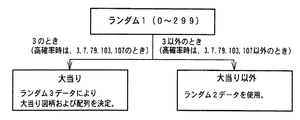
そして、CPU56は、ステップS51で読み出した値、すなわち抽出されている大当り判定用乱数の値にもとづいて当たり/はずれを決定する(ステップS53)。ここでは、大当り図柄判定用乱数は0〜299の範囲の値をとることにする。図10に示すように、低確率時には例えばその値が「3」である場合に「大当り」と決定し、それ以外の値である場合には「はずれ」と決定する。高確率時には例えばその値が「3」,「7」,「79」,「103」,「107」のいずれかである場合に「大当り」と決定し、それ以外の値である場合には「はずれ」と決定する。
【0052】
大当たりと判定されたときには、大当り図柄決定用乱数(ランダム3)を抽出しその値に従って大当り図柄を決定する(ステップS54)。また、リーチ種類決定用乱数(ランダム5)を抽出しその値にもとづいてリーチ種類を決定する(ステップS57)。
【0053】
はずれと判定された場合には、CPU56は、リーチとするか否か判定する(ステップS58)。例えば、リーチ判定用の乱数であるランダム4の値が「105」〜「1530」のいずれかである場合には、リーチとしないと決定する。そして、リーチ判定用乱数の値が「0」〜「104」のいずれかである場合にはリーチとすることを決定する。リーチとすることを決定したときには、CPU56は、リーチ図柄の決定を行う。
【0054】
この実施の形態では、ランダム2−1の値に従って左右図柄を決定する(ステップS59)。また、ランダム2−2の値に従って中図柄を決定する(ステップS60)。すなわち、ランダム2−1およびランダム2−2の値の0〜15の値に対応したいずれかの図柄が停止図柄として決定される。ここで、決定された中図柄が左右図柄と一致した場合には、中図柄に対応した乱数の値に1加算した値に対応する図柄を中図柄の確定図柄として、大当たり図柄と一致しないようにする。
【0055】
さらに、CPU56は、リーチ種類決定用乱数(ランダム5)を抽出しその値にもとづいてリーチ種類を決定する(ステップS57)。
【0056】
ステップS58において、リーチしないことに決定された場合には、ランダム2−1〜2−3の値に応じて左右中図柄を決定する(ステップS61)。なお、後述するように、この実施の形態では、高確率状態では、はずれ時の変動パターンとして変動時間が短縮されたものも使用される。そこで、高確率状態では、CPU56は、通常のはずれ時の変動パターンを用いるか短縮された変動パターンを用いるのかを、例えば所定の乱数等を用いて決定する。
【0057】
以上のようにして、始動入賞にもとづく図柄変動の表示態様が大当たりとするか、リーチ態様とするか、はずれとするか決定され、それぞれの停止図柄の組合せが決定される。
【0058】
なお、ステップS57において決定されるリーチ種類は、リーチ時の図柄の可変表示期間を示すものである。後で詳しく説明するが、この実施の形態では、リーチ時には、15秒、29秒および40秒のうちのいずれかの可変表示期間が用いられる。従って、ステップS57では、抽出されたランダム5の値に応じて、3種類の期間のうちのいずれかが決定される。そして、表示制御手段は、各可変表示時間のそれぞれについて複数用意されているリーチ種類の中から使用するものを決定する。すなわち、遊技制御手段では、大まかなリーチ種類が決定される。
【0059】
また、高確率状態において、次に大当たりとなる確率が上昇するとともに、7セグメントLEDによる可変表示器10の可変表示の確定までの時間が短縮され、かつ、可変表示器10の可変表示結果にもとづく当たり時の可変入賞球装置15の開放回数および開放時間が高められるようにパチンコ遊技機1が構成されていてもよいし、可変表示器10の可変表示結果にもとづく当たりの確率が高くなるように構成されていてもよい。また、それらのうちのいずれか一つまたは複数の状態のみが生ずるパチンコ遊技機1においても本発明は適用可能である。
【0060】
例えば、可変表示部9の停止図柄の組合せが特定図柄となった場合に、大当たりとなる確率は上昇しないが可変表示器10の可変表示結果にもとづく当たり時の可変入賞球装置15の開放回数および開放時間が高められる遊技機においても、リーチとすることが決定されたら、左右の停止図柄を特定図柄の表示態様と一致させるか否か、すなわちどの図柄でリーチ状態を発生させるかが所定の乱数等の手段によって決定される遊技機においても本発明を適用可能である。
また、この実施の形態で用いられた乱数および乱数値の範囲は一例であって、どのような乱数を用いてもよいし、範囲設定も任意である。
【0061】
図11は、CPU56が実行する特別図柄プロセス処理のプログラムの一例を示すフローチャートである。図11に示す特別図柄プロセス処理は、図6のフローチャートにおけるステップS11の具体的な処理である。CPU56は、特別図柄プロセス処理を行う際に、その内部状態に応じて、図11に示すステップS300〜S309のうちのいずれかの処理を行う。各処理において、以下のような処理が実行される。
【0062】
特別図柄変動待ち処理(ステップS300):始動入賞口14(この実施の形態では可変入賞球装置15の入賞口)に打球入賞して始動口センサ17がオンするのを待つ。始動口センサ17がオンすると、始動入賞記憶数が満タンでなければ、始動入賞記憶数を+1するとともに大当り決定用乱数を抽出する。すなわち、図8に示された処理が実行される。
特別図柄判定処理(ステップS301):特別図柄の可変表示が開始できる状態になると、始動入賞記憶数を確認する。始動入賞記憶数が0でなければ、抽出されている大当り決定用乱数の値に応じて大当たりとするかはずれとするか決定する。すなわち、図9に示された処理の前半が実行される。
停止図柄設定処理(ステップS302):左右中図柄の停止図柄を決定する。すなわち、図9に示された処理の中半が実行される。
【0063】
リーチ動作設定処理(ステップS303):リーチ判定用乱数の値に応じてリーチ動作するか否か決定するとともに、リーチ種類決定用乱数の値に応じてリーチ時の変動期間を決定する。すなわち、図9に示された処理の後半が実行される。
【0064】
全図柄変動開始処理(ステップS304):可変表示部9において全図柄が変動開始されるように制御する。このとき、表示制御基板80に対して、左右中最終停止図柄と変動態様を指令する情報とが送信される。
【0065】
全図柄停止待ち処理(ステップS305):所定時間が経過すると、可変表示部9において表示される全図柄が停止されるように制御する。
【0066】
大当たり表示処理(ステップS306):停止図柄が大当たり図柄の組み合わせである場合には、内部状態(プロセスフラグ)をステップS307に移行するように更新する。そうでない場合には、内部状態をステップS309に移行するように更新する。なお、大当たり図柄の組み合わせは、左右中図柄が揃った組み合わせである。また、左右図柄が揃うとリーチとなる。
【0067】
大入賞口開放開始処理(ステップS307):大入賞口を開放する制御を開始する。具体的には、カウンタやフラグを初期化するとともに、ソレノイド21を駆動して大入賞口を開放する。
【0068】
大入賞口開放中処理(ステップS308):大入賞口ラウンド表示の表示制御コマンドデータが表示制御基板80に送出する制御や大入賞口の閉成条件の成立を確認する処理等を行う。大入賞口の閉成条件が成立したら、大当り遊技状態の終了条件が成立していなければ内部状態をステップS307に移行するように更新する。大当り遊技状態の終了条件が成立していれば、内部状態をステップS309に移行するように更新する。
【0069】
大当たり終了処理(ステップS309):大当たり遊技状態が終了したことを遊技者に報知するための表示を行う。その表示が終了したら、内部フラグ等を初期状態に戻し、内部状態をステップS300に移行するように更新する。
【0070】
上述したように、始動入賞口14に打球が入賞すると、基本回路53は、ステップS11(図6参照)の特別図柄プロセス処理において、大当たりとするかはずれとするか、停止図柄および可変表示期間を決定するが、その決定に応じた表示制御コマンドを表示制御基板80の表示制御用CPU101に与える。表示制御用CPU101は、主基板31からの表示制御コマンドに応じて可変表示部9の表示制御を行う。
【0071】
次に、図柄の変動を具体例を用いて説明する。
図12は、この実施の形態で用いられる左右中図柄の例を示す説明図である。図12に示すように、この実施の形態では、左右中図柄として表示される各図柄は、左右中で同一の12図柄である。可変表示時には、各図柄は図柄番号順に表示され、図柄番号12の図柄が表示されると、次に、図柄番号1の図柄が表示される。そして、左右中図柄が、例えば、「一」、「二」、「七」、「八」、「下駄」または「おにぎり」で揃って停止すると高確率状態となる。すなわち、それらが確変図柄である。
【0072】
図13〜図16に示すように、この実施の形態では、図柄の可変表示期間を特定可能な表示制御コマンドすなわち可変表示パターンを特定可能な表示制御コマンドおよび全図柄の停止を指示する表示制御コマンドと、特別図柄の停止図柄を示す表示制御コマンドとがある。図13に示すように、この例では、可変表示期間を特定可能な表示制御コマンドとして、「はずれ」、「確変時変動」、「リーチ1」、「リーチ2」および「リーチ3」がある。
【0073】
図14には、左図柄の停止図柄を示す表示制御コマンドが示されている。図14に示すように、2バイトの制御データCMD1,CMD2で構成される表示制御コマンドによって停止図柄が指定される。なお、それらの指定において、1バイト目の制御データCMD1の値は、「8B(H)」である。
【0074】
図15には、中図柄の停止図柄を示す表示制御コマンドが示されている。図15に示すように、2バイトの制御データCMD1,CMD2で構成される表示制御コマンドによって停止図柄が指定される。なお、それらの指定において、1バイト目の制御データCMD1の値は、「8C(H)」である。
【0075】
図16には、右図柄の停止図柄を示す表示制御コマンドが示されている。図16に示すように、2バイトの制御データCMD1,CMD2で構成される表示制御コマンドによって停止図柄が指定される。なお、それらの指定において、1バイト目の制御データCMD1の値は、「8D(H)」である。
【0076】
図17は、主基板31から表示制御基板80に送信される表示制御コマンドを示す説明図である。図17に示すように、この実施の形態では、表示制御コマンドは、表示制御信号CD0〜CD7の8本の信号線で主基板31から表示制御基板80に送信される。また、主基板31と表示制御基板80との間には、ストローブ信号を送信するための表示制御信号INTの信号線、表示制御基板80の電源となる+5V,+12Vの供給線、および接地レベルを供給するための信号線も配線されている。
【0077】
図18は、主基板31から遊技制御基板80に与えられる表示制御コマンドの送出タイミングの例を示すタイミング図である。この例では、表示制御コマンドデータを構成する2バイトの表示制御データは、図18に示すように、2ms毎に送出される。そして、各表示制御データに同期してストローブ信号(表示制御信号INT)が出力される。表示制御用CPU101には、ストローブ信号の立ち上がりで割込がかかるので、表示制御用CPU101は、割込処理プログラムによって各表示制御データを取り込むことができる。
【0078】
図19は、変動開始時から変動終了時までの間に主基板31から表示制御基板80に送出される図柄変動に関する表示制御コマンドの送出タイミングを示すタイミング図である。図19に示すように、図柄の変動開始時には、変動開始を指示するための表示制御コマンド(変動期間を特定可能なコマンド)が送出される。変動開始を指示するための表示制御コマンドは、図13に示されたコマンド[80H,00H]〜[80H,05H]のいずれかである。次いで、左右中図柄の停止図柄を示す表示制御コマンドが送出される。そして、変動期間終了時に、「全図柄停止」を指示するコマンド[80H,0FH]が送出される。
【0079】
このように、この実施の形態では、図柄変動に関しては、可変表示部9に可変表示される図柄の変動期間と停止図柄を特定可能な情報のみを遊技制御手段すなわち主基板31のCPU56から表示制御手段に送出する。そして、変動期間終了時に全図柄停止を示す表示制御コマンドを送出する。従って、1回の図柄変動について遊技制御手段から表示制御手段に送出される表示制御コマンドの数が低減されている。
【0080】
以下、図20〜図21を参照して特別図柄の変動パターンの例について説明する。図20は、リーチとしないはずれ時の図柄の変動の一例を示すタイミング図である。また、図21は、リーチ時(大当りの場合および大当りとしない場合)の図柄の変動の一例を示すタイミング図である。
【0081】
この実施の形態では、主基板31から「はずれ」を示す表示制御コマンドを受信した場合には、表示制御用CPU101は、図20(A)に示すように、特別図柄を7秒間可変表示する。ただし、この実施の形態では、左図柄、右図柄、中図柄の順に停止し、その後、左図柄および右図柄は暫く揺れ変動する。揺れ変動とは、図柄が上下や左右に揺れるような表示がなされることをいう。揺れ変動は、最終停止図柄(確定図柄)が表示されるまで行われる。
【0082】
そして、主基板31から「全図柄停止」を示す表示制御コマンドを受信すると、特別図柄は最終的に停止(確定)する。すなわち、左右の特別図柄の揺れ変動状態を終了させて左右中図柄が動かない確定状態になる。なお、中図柄も、パターンc(減速)による変動の後に揺れ動作を行い、その後確定状態になるようにしてもよい。また、この場合には、特別図柄の確定図柄ははずれ図柄である。
【0083】
主基板31から「確変時変動」を示す表示制御コマンドを受信した場合には、表示制御用CPU101は、図20(B)に示すように、特別図柄を4秒間可変表示する。この場合には、特別図柄は同時に停止する。また、特別図柄の確定図柄ははずれ図柄である。
【0084】
図柄が変動している間、表示制御用CPU101は、所定の背景が表示されるように表示制御を行うとともに、画面中に所定のキャラクタを表示して適宜キャラクタを運動させるように表示制御を行う。具体的には、背景およびキャラクタをVDP103に通知する。すると、VDP103は、指示された背景の画像データを作成する。また、指示されたキャラクタの画像データを作成し背景画像と合成する。さらに、VDP103は、合成画像に、特別図柄の画像データを合成する。VDP103は、キャラクタが運動するような表示制御および図柄が変動するような表示制御も行う。すなわち、あらかじめ決められている運動パターンに従ってキャラクタの形状および表示位置を変える。また、表示制御用CPU101から通知される変動速度に応じて図柄表示位置を変えていく。
【0085】
また、表示制御用CPU101は、左右図柄が一致しない図柄で確定させるために、所定のタイミングで確定図柄の数図柄前の図柄に差し替え表示制御する。
【0086】
図21(A)は、主基板31から「リーチ1」の表示制御コマンドが送出されたときに表示される変動パターンの例を示す。表示制御用CPU101は、リーチ1が通知されると、特別図柄を15秒間可変表示する。特別図柄は、左図柄、右図柄、中図柄の順に停止し、その後、左図柄および右図柄は暫く揺れ変動する。揺れ変動は、最終停止図柄(確定図柄)が表示されるまで行われる。
【0087】
主基板31から「全図柄停止」を示す表示制御コマンドを受信すると、特別図柄は確定する。すなわち、左右の図柄の揺れ変動状態を終了させて左右中図柄が動かない確定状態になる。
【0088】
図21(B)は、主基板31から「リーチ2」の表示制御コマンドが送出されたときに表示される変動パターンの例を示す。表示制御用CPU101は、リーチ2が通知されると、特別図柄を29秒間可変表示する。特別図柄は、やはり、左図柄、右図柄、中図柄の順に停止し、その後、左図柄および右図柄は暫く揺れ変動する。そして、主基板31から「全図柄停止」を示す表示制御コマンドを受信すると、特別図柄は最終的に確定する。
【0089】
図21(C)は、主基板31から「リーチ3」の表示制御コマンドが送出されたときに表示される変動パターンの例を示す。表示制御用CPU101は、リーチ3が通知されると、特別図柄を40秒間可変表示する。特別図柄は、やはり、左図柄、右図柄、中図柄の順に停止し、その後、左図柄および右図柄は暫く揺れ変動する。そして、主基板31から「全図柄停止」を示す表示制御コマンドを受信すると、特別図柄は最終的に確定する。
【0090】
なお、図19には、それぞれのリーチについて各1種類の可変表示パターンが示されたが、それぞれのリーチについて、複数種類の可変表示パターンが用いられる。表示制御用CPU101は、所定の乱数等を用いて、どの可変表示パターンを用いるのか決定する。
【0091】
以下、上述した表示例を実現するための遊技制御手段および表示制御手段の制御について説明する。
図22は、図11に示された特別図柄プロセス処理における全図柄変動開始処理(ステップS304)を示すフローチャートである。ステップS303のリーチ動作設定処理において大当りとするか否かとリーチ種類とが決定されると、それらを指示するための表示制御コマンドの送出制御が行われるのであるが、ステップS304では、CPU56は、まず、コマンドの送出完了を待つ(ステップS304a)。なお、コマンド送出完了は、メイン処理(図6参照)中の表示制御データ出力処理(ステップS5)から通知される。
【0092】
この実施の形態では、CPU56は、図柄の変動を開始させるときに、図15に示された可変表示パターンを特定可能なコマンドと左右中の停止図柄を示す表示制御コマンドとを表示制御基板80に送出する。よって、ステップS304aのコマンド送信完了処理では、それら全てのコマンドの送出が完了したか否かが確認される。
【0093】
表示制御コマンドの送出が完了すると、CPU56は、表示制御基板80に通知した変動時間を測定するための変動時間タイマをスタートする(ステップS304b)。そして、ステップS305に移行するように、特別図柄プロセスフラグを更新する(ステップS304c)。
【0094】
図23は、図11に示された特別図柄プロセス処理における全図柄停止待ち処理(ステップS305)を示すフローチャートである。ステップS305では、CPU56は、変動時間タイマがタイムアップしたか否か確認する(ステップS305a)。タイムアップしたら、全図柄停止を指示する表示制御コマンドを設定する(ステップS305b)。そして、表示制御コマンドデータ送出要求をセットし(ステップS305c)、ステップS306に移行するように、特別図柄プロセスフラグを更新する(ステップS305d)。なお、表示制御コマンドデータ送出要求は、メイン処理(図6参照)中の表示制御データ設定処理(ステップS4)で参照される。
【0095】
図24は、表示制御データ設定処理(図6に示されたメイン処理におけるステップS4)の動作例を示すフローチャートである。表示制御データ設定処理において、CPU56は、まず、データ送出中フラグがセットされているか否か確認する(ステップS411)。セットされていなければ、表示制御コマンドデータの送出要求フラグがセットされているか否か確認する(ステップS412)。送出要求フラグがセットされていれば、送出要求フラグをリセットする(ステップS413)。また、送出すべき表示制御コマンドデータを出力データ格納領域に設定するとともに(ステップS414)、ポート出力要求をセットする(ステップS416)。なお、表示制御コマンドデータの送出要求フラグは、特別図柄プロセス処理においてセットされる。また、データ送出中フラグは、後述する表示制御データ出力処理においてセットされる。
【0096】
図25は、図6に示されたメイン処理における表示制御データ出力処理(ステップS5)を示すフローチャートである。表示制御データ出力処理において、CPU56は、ポート出力要求がセットされているか否か判定する(ステップS421)。ポート出力要求がセットされている場合には、ポート出力要求をリセットし(ステップS422)、ポート格納領域の内容(表示制御コマンドの1バイト目)を表示制御コマンド送出用の出力ポートに出力する(ステップS423)。そして、ポート出力カウンタを+1する(ステップS424)。さらに、INT信号をローレベル(オン状態)にし(ステップS425)、データ送出中フラグをオンする(ステップS426)。
【0097】
ポート出力要求がセットされていない場合には、ポート出力カウンタの値が0であるか否か判定する(ステップS431)。ポート出力カウンタの値が0でない場合には、ポート出力カウンタの値が1であるか否か確認する(ステップS432)。ポート出力カウンタの値が1である場合には、表示制御コマンドの1バイト目に関するINT信号オフタイミングになっているので、INT信号をオフ(=1)にする(ステップS433)。また、ポート出力カウンタの値を1増やす(ステップS434)。
【0098】
ポート出力カウンタの値が2である場合には(ステップS435)、表示制御コマンドの2バイト目の出力タイミングになっているので、ポート格納領域の内容(表示制御コマンドの2バイト目)を出力ポートに出力する(ステップS436)。そして、ポート出力カウンタを+1する(ステップS437)。さらに、INT信号をローレベルにする(ステップS438)。
【0099】
そして、ポート出力カウンタの値が2でない場合には、すなわち3である場合には、表示制御コマンドの2バイト目に関するINT信号オフタイミングになっているので、ポート出力カウンタの値をクリアするとともに(ステップS441)、INT信号をオフ(ハイレベル)にする(ステップS442)。また、データ送出中フラグをオフする(ステップS443)。
【0100】
この実施の形態では、図25に示された表示制御データ出力処理は2msに1回実行される。従って、図25に示されたデータ出力処理によって、図18に示されたように、2ms毎に1バイトのデータが出力される。
【0101】
次に、表示制御用CPU101の動作を説明する。
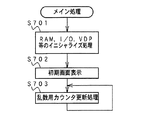
図26は、表示制御用CPU101のメイン処理を示すフローチャートである。メイン処理では、表示制御用CPU101は、まず、RAM、I/OポートおよびVDP103等を初期化する(ステップS701)。そして、可変表示部9に初期画面が出現するように表示制御する(ステップS702)。その後、乱数更新処理(乱数を生成するカウンタの更新処理)を繰り返し実行する(ステップS703)。この実施の形態では、乱数は、可変表示パターンを決定するのに用いられる。例えば、「リーチ1」を示す表示制御コマンドを受信すると、乱数値に応じて、リーチ1の複数の可変表示パターンから1つのパターンを選択する。
【0102】
また、この実施の形態では、実際の変動制御等は、タイマ割込処理によって行われる。タイマ割込は、例えば2ms毎に発生する。図27に示すように、タイマ割込処理では、表示制御用CPU101は、表示制御プロセス処理(ステップS711)を実行する。表示制御プロセス処理では、表示制御プロセスフラグの値に応じた表示制御処理が行われる。
【0103】
主基板31からの表示制御コマンドは、IRQ2割込によって表示制御用CPU101に受信される。図28は、表示制御用CPU101のIRQ2割込処理を示すフローチャートである。IRQ2割込処理において、表示制御用CPU101は、まず、データ受信中フラグがセットされているか否か確認する(ステップS601)。セットされていなければ、この割込が表示制御コマンドデータにおける第1バイトの表示制御データ送出による割込である。そこで、ポインタをクリアするとともに(ステップS602)、データ受信中フラグをセットする(ステップS603)。そして、ステップS604に移行する。ポインタは、表示制御用CPU101が内蔵しているRAMにおける表示制御コマンドデータ格納エリアにおける何バイト目に受信データを格納するか指し示すものである。
【0104】
データ受信中フラグがセットされている場合には、ストローブ信号がオフしたら(ステップS604)、表示制御用CPU101は、入力ポートからデータを入力し、表示制御コマンドデータ格納エリアにおいてポインタによって示されているアドレスに、入力データを格納する(ステップS605)。
【0105】
そして、表示制御用CPU101は、ポインタの値を+1する(ステップS606)。そして、ポインタの値が2になった場合には(ステップS607)、2バイトで構成される表示制御コマンドデータの受信が完了したことになるので、データ受信完了フラグをセットするとともに、データ受信中フラグをリセットする(ステップS608,S609)。以上のような処理によって、表示制御データCMD1,CMD2が、表示制御基板80において受信される。
【0106】
図29は、図27に示されたタイマ割込処理における表示制御プロセス処理(ステップS711)を示すフローチャートである。表示制御プロセス処理では、表示制御プロセスフラグの値に応じてステップS720〜S870のうちのいずれかの処理が行われる。各処理において、以下のような処理が実行される。
【0107】
表示制御コマンド受信待ち処理(ステップS720):IRQ2割込処理によって、変動時間を特定可能な表示制御コマンドを受信したか否か確認する。
【0108】
リーチ動作選択処理(ステップS750):リーチ時には、各可変表示パターンのうちのいずれのパターンを使用するのかを乱数を用いて決定する。
【0109】
全図柄変動開始処理(ステップS780):左右中図柄の変動が開始されるように制御する。
【0110】
図柄変動中処理(ステップS810):変動パターンを構成する各変動状態(変動速度や背景、キャラクタ)の切替タイミングを制御するとともに、変動時間の終了を監視する。また、左右図柄の停止制御を行う。
【0111】
全図柄停止待ち設定処理(ステップS840):変動時間の終了時に、全図柄停止を指示する表示制御コマンドを受信していたら、図柄の変動を停止し最終停止図柄(確定図柄)を表示する制御を行う。
【0112】
大当り表示処理(ステップS870):変動時間の終了後、確変継続回数を表示する制御等を行う。
【0113】
図30は、リーチ動作選択処理(ステップS750)を示すフローチャートである。リーチ動作選択処理において、表示制御用CPU101は、まず、ステップS720で受信を確認した変動時間を特定可能な表示制御コマンドから、リーチにもならないはずれか否か判断する(ステップS751)。具体的には、「はずれ」または「確変時変動」の表示制御コマンドを受信したか否か判断する。
【0114】
はずれであるならば、左右の停止図柄が異なっているものであるか否か確認する(ステップS752)。一致していた場合には、右停止図柄を1図柄ずらしたものとする(ステップS753)。そして、左右中の停止図柄を所定の記憶エリアに格納する(ステップS754)。また、監視タイマに7.1秒を設定する(ステップS755)。7.1秒は、はずれ時の変動時間7秒に対して余裕を持たせた値であり、監視タイマがタイムアウトする前に全図柄停止を指定するコマンドを受信できなかったときには所定の処理が行われる。
【0115】
ステップS751において、はずれでなかったら、すなわち、「リーチ1」〜「リーチ3」のいずれかの表示制御コマンドを受信していたら、左右の停止図柄が同一か否か確認する(ステップS756)。異なっていた場合には、右停止図柄を左停止図柄と同じものにする(ステップS757)。そして、左右中の停止図柄を所定の記憶エリアに格納する(ステップS758)。また、表示制御用CPU101は、「リーチ1」〜「リーチ3」に応じた変動時間に0.1秒を加算した値を監視タイマに設定する(ステップS759)。そして、リーチ態様すなわち可変表示パターンを決定する(ステップS760)。
【0116】
以上のように、この実施の形態では、表示制御用CPU101は、可変表示を開始させる際に主基板31から送出された変動期間を特定可能なコマンドと受信した左右中停止図柄を示すコマンドとが矛盾しているときには停止図柄を補正する。従って、何らかの原因で左右中停止図柄を示すコマンドに誤りが生じたととしてもその誤りは是正される。誤りとは、例えば、主基板31から表示制御基板80に至るケーブルにノイズが乗ってコマンドにビット誤りが生じたような場合である。この結果、遊技制御手段が決定したはずれ/リーチと矛盾するような確定図柄の表示がなされることが防止される。
【0117】
そして、表示制御用CPU101は、可変表示パターンに応じたプロセステーブルを使用することを決定する(ステップS762)。各プロセステーブルには、その可変表示パターン中の各変動状態(変動速度やその速度での変動期間等)が設定されている。また、各プロセステーブルはROMに設定されている。その後、表示制御用CPU101は、表示制御プロセスフラグの値を全図柄変動開始処理(ステップS780)に対応した値に変更する(ステップS763)。
【0118】
図31は、プロセステーブルの構成例を示す説明図である。それぞれの可変表示パターンに対応した各プロセステーブルには、時系列的に、特別図柄の変動速度やその速度での変動期間、背景やキャラクタの切替タイミング等が設定されている。また、ある速度での変動期間を決めるためのプロセスタイマ値も設定されている。また、各プロセステーブルは、複数の3バイト単位のプロセスデータで構成されている。
【0119】
例えば、図20(A)に示された可変表示パターンに対応したプロセステーブルにおいて、最初のプロセスデータ(3バイト)には、特別図柄の左右中図柄を低速で変動させること、および、次の表示状態切り替えタイミングまでの時間を示すプロセスタイマ値が設定されている。最初の変動はパターンaによる変動(加速)であって、まず、低速変動を開始すべきだからである。
【0120】
以降、表示状態をどのように切り替えるのかと、次の表示状態切り替えタイミングまでの時間を示すプロセスタイマ値とが順次設定されている。なお、表示状態切り替えタイミングとは、特別図柄の表示図柄切替タイミングであるが、さらに、背景およびキャラクタの切り替えタイミングや図柄の差し替えをすべきタイミングも含まれる。
【0121】
よって、表示制御用CPU101は、プロセスタイマのタイムアップによって何らかの表示状態を変更しなければならないことを知ることができる。そして、変更すべき表示状態は、プロセステーブルにおける次のプロセスデータの3バイト目の設定値から知ることができる。
【0122】
図32は、全図柄変動開始処理(ステップS780)を示すフローチャートである。全図柄変動開始処理において、表示制御用CPU101は、使用することが決定されたプロセステーブルの最初に設定されているプロセスタイマ値でタイマをスタートさせる(ステップS781)。また、3バイト目に設定されている変動状態を示すデータにもとづいて図柄変動制御、背景およびキャラクタの表示制御を開始する(ステップS782)。そして、表示制御プロセスフラグの値を図柄変動中処理(ステップS810)に対応した値に変更する(ステップS783)。
【0123】
図33は、図柄変動中処理(ステップS810)を示すフローチャートである。図柄変動中処理において、表示制御用CPU101は、プロセスタイマがタイムアウトしたか否か確認する(ステップS811)。プロセスタイマがタイムアウトした場合には、プロセステーブル中のデータを示すポインタを+3する(ステップS812)。そして、ポインタが指す領域のデータが終了コードであるか否か確認する(ステップS813)。終了コードでなければ、ポインタが指すプロセスデータの3バイト目に設定されている変動状態を示すデータにもとづいて図柄変動制御、背景およびキャラクタの表示制御を変更するとともに(ステップS814)、1,2バイト目に設定されているプロセスタイマ値でタイマをスタートさせる(ステップS815)。
【0124】
ステップS813で、終了コードであれば、表示制御プロセスフラグの値を全図柄停止待ち処理(ステップS840)に対応した値に変更する(ステップS816)。
【0125】
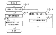
図34は、全図柄停止待ち処理(ステップS840)を示すフローチャートである。全図柄停止待ち処理において、表示制御用CPU101は、「全図柄停止」を指示する表示制御コマンドを受信しているか否か確認する(ステップS841)。全図柄停止を指示する表示制御コマンドを受信していれば、決定されている停止図柄で左右中図柄を最終停止(確定)させる制御を行う(ステップS842)。そして、表示制御プロセスフラグの値を大当り表示処理(ステップS870)に対応した値に設定する(ステップS843)。
【0126】
「全図柄停止」を指定する表示制御コマンドを受信していない場合には、監視タイマがタイムアウトしているかどうか確認する(ステップS844)。タイムアウトした場合には、何らかの異常が発生したと判断して、可変表示部9にエラー画面を表示する制御を行う(ステップS845)。
【0127】
図35は、大当り表示処理(ステップS870)を示すフローチャートである。大当り表示処理において、表示制御用CPU101は、まず、ステップS870の処理が初めて実行されたのか否か確認する(ステップS871)。2回目以降の実行時には、ステップS877に移行する。初めての処理であれば、表示制御用CPU101は、変動回数カウンタの値を確認する(ステップS872)。変動回数カウンタの値が0であればステップS877に移行する。なお、変動回数カウンタの値が0であるということは、確変状態ではないことを意味する。
【0128】
変動回数カウンタの値が0でなければ、変動回数カウンタの値を−1する(ステップS873)。ここで、変動回数カウンタの値が0になった場合には(ステップS874)、可変表示部9に表示されている変動残り回数表示を消去する(ステップS876)。変動回数カウンタの値が0でなければ、可変表示部9に表示されている変動残り回数表示を1減らす(ステップS875)。
【0129】
その後、大当りとなった場合には、主基板31から送信される大当り遊技状態における表示制御コマンドにもとづいて可変表示部9の表示制御を行う。例えば、ラウンド数の表示等が行われる。そして、大当り遊技が終了すると(ステップS877)、表示制御用CPU101は、左右中の停止図柄が確変図柄であったか否か確認する(ステップS878)。確変図柄であった場合には、遊技機は確変状態に入る。この実施の形態では、確変状態が終了する条件は、図柄の変動が所定回行われた場合である。そして、所定回は、奇数の確変図柄で大当りした場合には「10」とし、偶数の確変図柄で大当りした場合には「4」とする。なお、この実施の形態では、奇数の確変図柄は、「一」、「七」、「下駄」であり、偶数の確変図柄は「二」、「八」、「おにぎり」である。また、大当り遊技が終了したことは一般に主基板31から所定のコマンドによって通知されるが、そのコマンドにエラーが生じて正常に受信できなくても、表示制御用CPU101は、その次に受信される表示制御コマンド(例えば、次の変動開始を示すコマンド)の受信に応じてステップS877の判断を「Y」とすることができる。
【0130】
また、確変状態では、表示制御用CPU101は、確変終了までの残り変動回数を可変表示部9に表示する。そこで、表示制御用CPU101は、奇数の確変図柄で大当りした場合には変動回数カウンタに「10」をセットし(ステップS879,S880)、偶数の確変図柄で大当りした場合には変動回数カウンタに「4」をセットする(ステップS879,S881)。そして、変動残り回数表示を開始する(ステップS882)。すなわち、変動回数カウンタの値を可変表示部9に表示する。その後、表示制御プロセスフラグの値を表示制御コマンド受信待ち(ステップS720)に対応した値に設定する(ステップS883)。なお、大当りではなくステップS870に移行してきた場合には、ステップS877およびS878から直ちにステップS883の処理に移行することになる。
【0131】
図36は、変動残り回数表示の一例を示す説明図である。(A)は、奇数の確変図柄で大当りした場合の変動残り回数表示の表示例を示す。また、(B)は、変動残り回数が1回となった場合の表示例を示す。そして、(C)は、変動回数カウンタの値が0になって変動残り回数表示が消去されたときの表示例を示す。ただし、この表示例では、確変状態が終了したことの報知もなされている。
【0132】
以上のように、この実施の形態では、確変状態に突入後確変状態が終了するまで、変動残り回数が表示される。そして、変動残り回数の表示制御は、表示制御用CPU101によって行われる。すなわち、表示制御用CPU101が図柄の変動を示す表示制御コマンド(この例では変動期間を特定可能なコマンド)の受信回数をカウントして、独自に回数表示の更新処理および消去処理を行う。従って、遊技制御手段すなわち主基板31のCPU56の制御負荷を増大させることなく、遊技者に変動残り回数をわかりやすく報知することができる。
【0133】
また、確変大当りによる大当り遊技終了後に変動残り回数が表示開始されるので、変動残り回数の表示が確変大当りによる大当り遊技の演出を阻害しないという効果がある。
【0134】
なお、この実施の形態では、奇数の確変図柄と偶数の確変図柄とで確変時の図柄変動可能回数を変えたが、それらは同じであってもよい。また、上記の例で用いられた図柄変動可能回数は単なる例の値である。さらに、この実施の形態では、表示制御用CPU101が主基板31から受信した停止図柄の表示制御コマンドから確変図柄か否かの判定を行ったが、確変図柄で大当りが発生するときに、その旨の表示制御コマンドを主基板31から表示制御基板80に対して送信するように構成してもよい。また、上記の例では、全図柄のうちの一部を確変図柄としたが、大当りが発生すると常に確変状態に突入するように構成された遊技機にも本発明を適用することができる。
【0135】
上記の実施の形態では、図柄変動に関しては、可変表示部9に可変表示される図柄の変動期間、停止図柄を特定可能な情報、および全図柄停止を示す表示制御コマンドのみを遊技制御手段から表示制御手段に送出したが、本発明による変動残り回数の表示制御方式は、図柄変動時に、より細かい情報が遊技制御手段から表示制御手段に送出されるように構成された遊技機にも適用可能である。
【0136】
【発明の効果】
以上のように、本発明によれば、遊技機を、表示制御手段が、確率変動を引き起こす大当りの終了後における可変表示を示すコマンドの入力回数を計数する計数手段と、計数手段の計数値にもとづいて高確率状態における可変表示残り回数を遊技者が認識可能に可変表示部に表示する残り回数表示制御手段とを含むように構成したので、遊技制御手段の負担を増大することなく、確変状態に関する報知を遊技者にとって認識しやすく報知することができる効果がある。
【0137】
表示制御手段のコマンド入力手段が、遊技制御手段から表示制御手段への方向にのみ信号を伝達可能な不可逆性情報入力手段である場合には、表示制御手段の回路に不正改造が加えられても、不正改造によって出力される信号が遊技制御手段側に伝わることはなく、遊技制御手段に不正な信号が入力されることを確実に防止できる効果がある。
【0138】
遊技制御手段が、可変表示開始に関連した時期に変動パターンを示すコマンドを出力し、全ての図柄を確定させるのに関連した時期に確定を指示する情報を送出するように構成されている場合には、表示制御手段が図柄確定時期を通知されることによって、図柄をより確実に確定させることができる。
【0139】
遊技制御手段のコマンド出力手段が、遊技制御手段から表示制御手段への方向にのみ信号を伝達可能な不可逆性情報出力手段である場合には、遊技制御手段に不正な信号が入力されることをより確実に防止できる効果がある。
【0140】
計数手段が、遊技制御手段からの確定を指示するコマンドの受信に応じて計数を行うように構成されている場合には、確実な残り回数表示を行うことができる効果がある。
【0141】
表示制御手段が、可変表示の確定に関連した時期に残り回数表示を更新するように構成されている場合には、遊技者に変動残り回数をよりわかりやすく報知することができる効果がある。
【0142】
変表示制御手段は、確率変動を引き起こす大当り遊技の終了に関連した時期に残り回数表示を開始し、残り回数が0となった時期に関連して残り回数表示を消去するように構成されている場合には、変動残り回数の表示が確変大当りによる大当り遊技の演出を阻害しないという効果がある。
【図面の簡単な説明】
【図1】 パチンコ遊技機を正面からみた正面図である。
【図2】 パチンコ遊技機の内部構造を示す全体背面図である。
【図3】 パチンコ遊技機の遊技盤を背面からみた背面図である。
【図4】 主基板における回路構成の一例を示すブロック図である。
【図5】 表示制御基板の回路構成を示すブロック図である。
【図6】 基本回路のメイン処理を示すフローチャートである。
【図7】 各乱数を示す説明図である。
【図8】 打球が始動入賞口に入賞したことを判定する処理を示すフローチャートである。
【図9】 図柄の変動方法を決定する処理を示すフローチャートである。
【図10】 大当たり判定の処理を示すフローチャートである。
【図11】 特別図柄プロセス処理を示すフローチャートである。
【図12】 可変表示部に表示される特別図柄の例を示す説明図である。
【図13】 図柄の可変表示期間を特定可能な表示制御コマンドおよび全図柄の停止を指示する表示制御コマンドを示す説明図である。
【図14】 左図柄の停止図柄の表示制御コマンドを示す説明図である。
【図15】 中図柄の停止図柄の表示制御コマンドを示す説明図である。
【図16】 右図柄の停止図柄の表示制御コマンドを示す説明図である。
【図17】 主基板から表示制御基板に送信される表示制御コマンドデータを示す説明図である。
【図18】 表示制御コマンドデータの送出タイミングの一例を示すタイミング図である。
【図19】 変動開始時から変動終了時までの間に送出される図柄変動に関する表示制御コマンドの送出タイミングを示すタイミング図である。
【図20】 リーチとしないはずれ時の図柄の変動の一例を示すタイミング図である。
【図21】 リーチ時の図柄の変動の例を示すタイミング図である。
【図22】 特別図柄プロセス処理における全図柄変動開始処理を示すフローチャートである。
【図23】 特別図柄プロセス処理における全図柄停止待ち処理を示すフローチャートである。
【図24】 表示制御データ設定処理の動作例を示すフローチャートである。
【図25】 表示制御データ出力処理を示すフローチャートである。
【図26】 表示制御用CPUのメイン処理を示すフローチャートである。
【図27】 表示制御用CPUのタイマ割込処理を示すフローチャートである。
【図28】 表示制御用CPUのIRQ2割込処理を示すフローチャートである。
【図29】 表示制御プロセス処理を示すフローチャートである。
【図30】 変動開始プロセス処理のリーチ動作選択処理を示すフローチャートである。
【図31】 表示制御プロセステーブルの構成例を示す説明図である。
【図32】 表示制御プロセス処理の全図柄変動開始処理を示すフローチャートである。
【図33】 表示制御プロセス処理の図柄変動中処理を示すフローチャートである。
【図34】 表示制御プロセス処理の全図柄停止待ち処理を示すフローチャートである。
【図35】 表示制御プロセス処理の大当り表示処理を示すフローチャートである。
【図36】 変動残り回数表示の一例を示す説明図である。
【符号の説明】
9 可変表示部
31 遊技制御基板(主基板)
53 基本回路
56 CPU
63 出力バッファ回路
80 表示制御基板
101 表示制御用CPU
103 VDP
105 入力バッファ回路[0001]
BACKGROUND OF THE INVENTION
The present invention relates to a gaming machine such as a pachinko gaming machine or a coin gaming machine, and particularly includes a variable display device whose display state can be changed, and a display result in the variable display device becomes a predetermined specific display mode. The present invention relates to a gaming machine that can be given a predetermined gaming value.
[0002]
[Prior art]
As a gaming machine, a variable display device having a variable display unit whose display state can be changed is provided, and a big hit game that is advantageous to the player when the display result of the variable display unit becomes a predetermined specific display mode Some are configured to transition to a state. The variable display device has a plurality of variable display units, and is usually configured to display the display results of the plurality of variable display units at different times. For example, a plurality of pieces of identification information (special symbols) such as symbols are variably displayed on the variable display portion. That the display result of the variable display unit is a combination of specific display modes determined in advance is usually referred to as “big hit”. Note that the game value is the right that the state of the variable winning ball device provided in the gaming area of the gaming machine is advantageous for a player who is likely to win a ball, or the advantageous state for a player. It is to generate.
[0003]
When the big hit occurs, for example, the big winning opening is opened a predetermined number of times, and the game shifts to a big hit gaming state where the hit ball is easy to win. And in each open period, if there is a prize for a predetermined number (for example, 10) of the big prize opening, the big prize opening is closed. And the number of times the special winning opening is opened is fixed to a predetermined number (for example, 16 rounds). An opening time (for example, 29.5 seconds) is determined for each opening, and even if the number of winnings does not reach a predetermined number, the big winning opening is closed when the opening time elapses. In addition, when a predetermined condition (for example, winning in a V zone provided in the big prize opening) is not established at the time when the big prize opening is closed, the big hit game even if the predetermined number of times is not reached The state ends.
[0004]
In addition, among the combinations of “out of” display modes other than the “big hit” combination, the display results are already derived and displayed at a stage where some of the display results of the plurality of variable display portions have not yet been derived and displayed. A state in which the display mode of the variable display unit satisfies a display condition that is a combination of specific display modes is referred to as “reach”. A player plays a game while enjoying how to generate a big hit.
[0005]
Some gaming machines improve the probability of generating a big hit when a predetermined condition is established. The predetermined condition is satisfied, for example, when the combination of the stop symbol of the special symbol becomes a combination of the predetermined symbol (probability variation symbol). A state in which the probability of generating a big hit is improved is called a probability variation (probability variation) state. The probability change state continues until a predetermined end condition is satisfied, but since the player is in a favorable situation during the probability change, whether the player has entered the probability change state and whether or not the probability change is currently in progress. Have a strong interest in
[0006]
Each game control described above is executed by game control means, and the game control means is generally configured to include a microcomputer, so that each game control is realized by a program executed by the microcomputer. The display control for the display means for performing the variable display described above is generally executed by a display control means having a configuration different from that of the game control means. Therefore, it is necessary for the game control means to transmit a display control command to the display control means.
[0007]
[Problems to be solved by the invention]
Normally, there is a limit on the capacity of the program storage area (ROM) that can be installed in a gaming machine, so if the amount of programs for realizing each game control can be reduced, a game with a more complicated performance will be realized as a whole. can do. However, if the display effect of variable display is to be increased, the control load related to the display of the game control means increases. In addition, if notification regarding the probability variation state in which the player is strongly interested is performed via the display control means, notification that is easy to recognize for the player is realized. If such a notification method is adopted, game control is realized. The control load related to the display of the means further increases.
[0008]
Therefore, the present invention provides a gaming machine capable of easily and easily recognizing a notification regarding a probability change state in which a player has a strong interest without increasing the burden of game control means. Objective.
[0009]
[Means for Solving the Problems]
The gaming machine according to the present invention includes a variable display unit having a plurality of display areas whose display states can be changed, and starts to change the identification information displayed in the display area in accordance with the establishment of the conditions for starting the change. A gaming machine that can be controlled in a gaming state advantageous to the player on the condition that the display result of information is in a predetermined specific display mode, a game control means for controlling the progress of the game, and a variable display unit Display control means for controlling the display of the game, and the game control means is a jackpot determining means for determining whether or not to win Yes Fluctuation pattern determining means for determining a variable display fluctuation pattern in the variable display section, and probability changing means capable of making the jackpot occurrence probability higher than the normal time by a predetermined number of variable displays after the jackpot. , At least with variation patterns Whether or not it is a big hit And a command output means for sending a command for performing a display related to the big hit to the display control means in a manner recognizable by the display control means. The control means is based on the command input means for inputting a command from the game control means, the counting means for counting the number of times of input of the command indicating the variable display after the end of the big hit causing the probability fluctuation, and the count value of the counting means. And a remaining number display control means for displaying the variable display remaining number in the high probability state on the variable display unit so that the player can recognize it.
[0010]
The command input means of the display control means may be an irreversible information input means capable of transmitting a signal only in the direction from the game control means to the display control means.
[0011]
The game control means will change the fluctuation pattern at the time related to the start of variable display. The It may be configured to output a command to indicate and send information instructing determination at a time related to determining all symbols.
[0012]
The command output means of the game control means may be an irreversible information output means capable of transmitting a signal only in the direction from the game control means to the display control means.
[0013]
The counting means may be configured to perform counting in response to reception of a command instructing determination from the game control means.
[0014]
The display control means may be configured to update the remaining number display at a time related to the determination of the variable display.
[0015]
The variable display control means is configured to start the remaining number display at a time related to the end of the jackpot game causing the probability variation, and to erase the remaining number display related to the time when the remaining number becomes zero. Also good.
[0016]
DETAILED DESCRIPTION OF THE INVENTION
Hereinafter, an embodiment of the present invention will be described with reference to the drawings.
First, the overall configuration of a pachinko gaming machine that is an example of a gaming machine will be described. 1 is a front view of the
[0017]
As shown in FIG. 1, the
[0018]
Near the center of the
[0019]
An open / close plate 20 that is opened by a
[0020]
The
[0021]
The hit ball fired from the hit ball launching device enters the
[0022]
When the combination of images in the
Further, when the stop symbol on the
[0023]
Next, the structure of the back surface of the
On the back surface of the
[0024]
The
[0025]
FIG. 3 is a rear view of the game board of the
[0026]
In order to perform the winning ball payout control, signals from the winning
[0027]
FIG. 4 is a block diagram illustrating an example of a circuit configuration in the
[0028]
Further, according to the data given from the
[0029]
The
[0030]
Further, an initial reset circuit 65 for resetting the
Note that there is also switch information input to the
[0031]
A ball hitting device for hitting and launching a game ball is driven by a drive motor 94 controlled by a circuit on the
[0032]
FIG. 5 is a block diagram showing a circuit configuration in the
[0033]
Then, the display control CPU 101 performs display control of the screen displayed on the
[0034]
5 also shows a
[0035]
The
[0036]
Further, in the
[0037]
Next, the operation of the gaming machine will be described.
FIG. 6 is a flowchart showing the operation of the
[0038]
Next, the CPU 56 performs a stack setting process for setting the designated address of the stack pointer (step S2). In this example, 00FFH is set in the stack pointer. Then, a system check process is performed (step S3). In the system check process, the CPU 56 determines whether or not an error is included in the RAM 55. If the error is included, the CPU 56 performs a process such as initializing the RAM 55.
[0039]
Next, after performing processing for setting command data sent to the
[0040]
Next, a process of outputting the contents of the storage area for various output data to each output port is performed (data output process: step S6). Also, the process of decrementing the lamp timer by 1 is performed, and when the lamp timer times out (= 0), the lamp data pointer is updated and a new value is set in the lamp timer (lamp timer process: step S7).
[0041]
Further, output data setting processing is performed for setting output data such as address data indicated by the lamp data pointer, jackpot information output to the hall management computer, start information, probability variation information, etc. in the storage area (step S8). Further, various abnormality diagnosis processes are performed by the self-diagnosis function provided in the
[0042]
Next, a process of updating each counter indicating each determination random number such as a big hit determination random number used for game control is performed (step S10).
FIG. 7 is an explanatory diagram showing each random number. Each random number is used as follows.
(1) Random 1: Decide whether or not to generate a big hit (for big hit judgment)
(2) Random 2-1 to 2-3: For determining the left and right out-of-line symbols
(3) Random 3: Determines the combination of symbols for jackpot (for determining jackpot symbols)
(4) Random 4: Decide whether or not to reach when falling off (for reach determination)
(5) Random 5: Determine the fluctuation time during reach (for determining reach type)
[0043]
In order to enhance the game effect, random numbers other than the random numbers (1) to (5) are also used.
In step S10, the CPU 56 counts up (adds 1) a counter for generating the jackpot determination random number (1) and the jackpot symbol determination random number (3). That is, they are determination random numbers.
[0044]
Next, the CPU 56 performs special symbol process processing (step S11). In the special symbol process control, corresponding processing is selected and executed according to a special symbol process flag for controlling the
[0045]
Further, the CPU 56 inputs the state of each switch via the switch circuit 58 and performs necessary processing according to the switch state (switch processing: step S13). Further, a process of sending audio data in process data, which will be described later, to the
[0046]
The
[0047]
The
After that, the
[0048]
Next, a method for determining a symbol variably displayed on the
[0049]
When the hit ball wins the
[0050]
As shown in FIG. 9, the CPU 56 confirms the value of the number of start winning prizes in the special symbol process processing in step S8 (step S50). If the starting winning memory number is not 0, the value stored in the random number value storage area corresponding to the starting winning memory number = 1 is read (step S51), the value of the starting winning memory number is decreased by 1, and each The value in the random value storage area is shifted (step S52). That is, the value stored in the random number value storage area corresponding to the starting winning memory number = n (n = 2, 3, 4) is stored in the random number value storing area corresponding to the starting winning memory number = n−1. .
[0051]
Then, the CPU 56 determines the winning / losing based on the value read in step S51, that is, the value of the extracted big hit determination random number (step S53). Here, the jackpot symbol determining random number takes a value in the range of 0-299. As shown in FIG. 10, at the time of low probability, for example, when the value is “3”, “big hit” is determined. When the probability is high, for example, when the value is any one of “3”, “7”, “79”, “103”, “107”, “big hit” is determined. It is determined that it is out of place.
[0052]
When it is determined that the jackpot is big, the jackpot symbol determining random number (random 3) is extracted and the jackpot symbol is determined according to the value (step S54). Further, a reach type determining random number (random 5) is extracted, and a reach type is determined based on the extracted value (step S57).
[0053]
If it is determined that there is a loss, the CPU 56 determines whether or not to reach (step S58). For example, when the value of random 4, which is a random number for reach determination, is any one of “105” to “1530”, it is determined not to reach. If the value of the reach determination random number is any one of “0” to “104”, it is determined to reach. When determining to reach, the CPU 56 determines the reach symbol.
[0054]
In this embodiment, the left and right symbols are determined according to the value of random 2-1 (step S59). Further, the medium symbol is determined according to the value of random 2-2 (step S60). That is, any symbol corresponding to 0 to 15 of random 2-1 and random 2-2 is determined as a stop symbol. Here, when the determined middle symbol matches the left and right symbols, the symbol corresponding to the value obtained by adding 1 to the random number corresponding to the middle symbol is set as the determined symbol of the middle symbol so as not to match the jackpot symbol To do.
[0055]
Further, the CPU 56 extracts the reach type determining random number (random 5) and determines the reach type based on the value (step S57).
[0056]
If it is decided not to reach in step S58, the left and right middle symbols are decided according to the random values 2-1 to 2-3 (step S61). As will be described later, in this embodiment, in a high probability state, a variation pattern with a shortened variation time is also used as a variation pattern at the time of loss. Therefore, in the high probability state, the CPU 56 determines whether to use the normal fluctuation pattern or the shortened fluctuation pattern using, for example, a predetermined random number.
[0057]
As described above, it is determined whether the display mode of the symbol variation based on the start winning is a big hit, a reach mode, or a deviation mode, and a combination of each stop symbol is determined.
[0058]
The reach type determined in step S57 indicates the symbol variable display period at the time of reach. As will be described in detail later, in this embodiment, at the time of reach, any of the variable display periods of 15 seconds, 29 seconds, and 40 seconds is used. Accordingly, in step S57, one of the three types of periods is determined according to the extracted
[0059]
Further, in the high probability state, the probability of the next big hit increases, the time until the variable display of the
[0060]
For example, when the combination of the stop symbols of the
Further, the random number and the range of the random value used in this embodiment are merely examples, and any random number may be used, and the range setting is also arbitrary.
[0061]
FIG. 11 is a flowchart showing an example of a special symbol process processing program executed by the CPU 56. The special symbol process shown in FIG. 11 is a specific process of step S11 in the flowchart of FIG. When performing the special symbol process, the CPU 56 performs any one of steps S300 to S309 shown in FIG. 11 according to the internal state. In each process, the following process is executed.
[0062]
Special symbol variation waiting process (step S300): Waiting for the
Special symbol determination process (step S301): When variable symbol special display can be started, the number of start winning memories is confirmed. If the start winning memorized number is not 0, it is determined whether to win or not depending on the value of the extracted big hit determination random number. That is, the first half of the process shown in FIG. 9 is executed.
Stop symbol setting process (step S302): The stop symbol of the middle left and right symbols is determined. That is, the middle half of the process shown in FIG. 9 is executed.
[0063]
Reach operation setting process (step S303): It is determined whether or not a reach operation is performed according to the value of the reach determination random number, and a change period during reach is determined according to the value of the reach type determination random number. That is, the second half of the process shown in FIG. 9 is executed.
[0064]
All symbol variation start processing (step S304): Control is performed so that the
[0065]
All symbols stop waiting process (step S305): When a predetermined time has elapsed, control is performed so that all symbols displayed on the
[0066]
Jackpot display processing (step S306): If the stop symbol is a combination of jackpot symbols, the internal state (process flag) is updated to shift to step S307. If not, the internal state is updated to shift to step S309. The jackpot symbol combination is a combination of right and left middle symbols. Reaching is achieved when the left and right symbols are aligned.
[0067]
Big winning opening opening process (step S307): Control for opening the big winning opening is started. Specifically, the counter and the flag are initialized, and the
[0068]
Processing for opening a special prize opening (step S308): Control for sending display control command data for the big prize opening round display to the
[0069]
Jackpot end process (step S309): A display for notifying the player that the jackpot gaming state has ended is performed. When the display is completed, the internal flag and the like are returned to the initial state, and the internal state is updated to shift to step S300.
[0070]
As described above, when a hit ball is won at the
[0071]
Next, the variation of symbols will be described using a specific example.
FIG. 12 is an explanatory diagram showing an example of left and right middle symbols used in this embodiment. As shown in FIG. 12, in this embodiment, the symbols displayed as the left and right middle symbols are the same 12 symbols in the left and right. At the time of variable display, each symbol is displayed in the symbol number order. When the
[0072]
As shown in FIGS. 13 to 16, in this embodiment, a display control command that can specify a variable display period of a symbol, that is, a display control command that can specify a variable display pattern, and a display control command that instructs to stop all symbols. And a display control command indicating a special symbol stop symbol. As shown in FIG. 13, in this example, display control commands that can specify the variable display period include “out of”, “probability change”, “reach 1”, “reach 2”, and “reach 3”.
[0073]
FIG. 14 shows a display control command indicating the stop symbol of the left symbol. As shown in FIG. 14, a stop symbol is designated by a display control command composed of 2-byte control data CMD1 and CMD2. In these designations, the value of the control data CMD1 in the first byte is “8B (H)”.
[0074]
FIG. 15 shows a display control command indicating the stop symbol of the middle symbol. As shown in FIG. 15, a stop symbol is designated by a display control command composed of 2-byte control data CMD1 and CMD2. In these designations, the value of the control data CMD1 in the first byte is “8C (H)”.
[0075]
FIG. 16 shows a display control command indicating the stop symbol of the right symbol. As shown in FIG. 16, a stop symbol is designated by a display control command composed of 2-byte control data CMD1 and CMD2. In these designations, the value of the control data CMD1 in the first byte is “8D (H)”.
[0076]
FIG. 17 is an explanatory diagram showing display control commands transmitted from the
[0077]
FIG. 18 is a timing chart showing an example of the transmission timing of the display control command given from the
[0078]
FIG. 19 is a timing chart showing the display timings of display control commands relating to symbol variations that are sent from the
[0079]
As described above, in this embodiment, with respect to the symbol variation, only the information that can specify the symbol variation period and the stop symbol variably displayed on the
[0080]
Hereinafter, an example of the variation pattern of the special symbol will be described with reference to FIGS. FIG. 20 is a timing chart showing an example of a change in symbol when the reach is not reached. FIG. 21 is a timing chart showing an example of symbol variation during reach (when a big hit and not a big hit).
[0081]
In this embodiment, when a display control command indicating “displacement” is received from the
[0082]
When the display control command indicating “stop all symbols” is received from the
[0083]
When receiving a display control command indicating “change during probability change” from the
[0084]
While the symbols are changing, the display control CPU 101 performs display control so that a predetermined background is displayed, and performs display control so that a predetermined character is displayed on the screen and the character is appropriately exercised. . Specifically, the background and the character are notified to the
[0085]
In addition, the display control CPU 101 controls the display to be replaced with symbols that are several symbols before the confirmed symbols at a predetermined timing in order to determine the symbols that do not match the left and right symbols.
[0086]
FIG. 21A shows an example of a variation pattern displayed when a display control command “
[0087]
When the display control command indicating “stop all symbols” is received from the
[0088]
FIG. 21B shows an example of a variation pattern displayed when a display control command “
[0089]
FIG. 21C shows an example of a variation pattern displayed when a display control command “
[0090]
In FIG. 19, one type of variable display pattern is shown for each reach, but a plurality of types of variable display patterns are used for each reach. The display control CPU 101 determines which variable display pattern to use using a predetermined random number or the like.
[0091]
Hereinafter, the control of the game control means and the display control means for realizing the display example described above will be described.
FIG. 22 is a flowchart showing all symbol variation start processing (step S304) in the special symbol process shown in FIG. When it is determined in the reach operation setting process in step S303 whether or not to win and the reach type is determined, display control command transmission control for instructing them is performed. In step S304, the CPU 56 first starts. Then, it waits for the completion of command transmission (step S304a). The command transmission completion is notified from the display control data output process (step S5) in the main process (see FIG. 6).
[0092]
In this embodiment, when starting the change of the symbol, the CPU 56 gives the display control board 80 a command that can specify the variable display pattern shown in FIG. 15 and a display control command that shows the left and right stop symbols. Send it out. Therefore, in the command transmission completion process in step S304a, it is confirmed whether or not transmission of all the commands has been completed.
[0093]
When the transmission of the display control command is completed, the CPU 56 starts a variation time timer for measuring the variation time notified to the display control board 80 (step S304b). Then, the special symbol process flag is updated so as to proceed to step S305 (step S304c).
[0094]
FIG. 23 is a flowchart showing the all symbol stop waiting process (step S305) in the special symbol process shown in FIG. In step S305, the CPU 56 checks whether or not the variable time timer has expired (step S305a). When the time is up, a display control command for instructing stop of all symbols is set (step S305b). Then, a display control command data transmission request is set (step S305c), and the special symbol process flag is updated so as to proceed to step S306 (step S305d). The display control command data transmission request is referred to in the display control data setting process (step S4) in the main process (see FIG. 6).
[0095]
FIG. 24 is a flowchart showing an operation example of the display control data setting process (step S4 in the main process shown in FIG. 6). In the display control data setting process, the CPU 56 first checks whether the data sending flag is set (step S411). If not set, it is checked whether or not the display control command data transmission request flag is set (step S412). If the transmission request flag is set, the transmission request flag is reset (step S413). Further, the display control command data to be sent is set in the output data storage area (step S414), and a port output request is set (step S416). The display control command data transmission request flag is set in the special symbol process. The data sending flag is set in the display control data output process described later.
[0096]
FIG. 25 is a flowchart showing the display control data output process (step S5) in the main process shown in FIG. In the display control data output process, the CPU 56 determines whether or not a port output request is set (step S421). If the port output request is set, the port output request is reset (step S422), and the contents of the port storage area (the first byte of the display control command) are output to the output port for sending the display control command ( Step S423). Then, the port output counter is incremented by 1 (step S424). Further, the INT signal is set to a low level (on state) (step S425), and the data sending flag is turned on (step S426).
[0097]
If the port output request is not set, it is determined whether or not the value of the port output counter is 0 (step S431). If the value of the port output counter is not 0, it is confirmed whether or not the value of the port output counter is 1 (step S432). When the value of the port output counter is 1, since the INT signal is turned off for the first byte of the display control command, the INT signal is turned off (= 1) (step S433). Also, the value of the port output counter is incremented by 1 (step S434).
[0098]
When the value of the port output counter is 2 (step S435), the output timing of the second byte of the display control command is reached, so the contents of the port storage area (second byte of the display control command) are output. (Step S436). Then, the port output counter is incremented by 1 (step S437). Further, the INT signal is set to a low level (step S438).
[0099]
When the value of the port output counter is not 2, that is, when it is 3, the INT signal OFF timing related to the second byte of the display control command is reached, so the value of the port output counter is cleared ( In step S441, the INT signal is turned off (high level) (step S442). Further, the data sending flag is turned off (step S443).
[0100]
In this embodiment, the display control data output process shown in FIG. 25 is executed once every 2 ms. Accordingly, the data output process shown in FIG. 25
[0101]
Next, the operation of the display control CPU 101 will be described.
FIG. 26 is a flowchart showing main processing of the display control CPU 101. In the main process, the display control CPU 101 first initializes the RAM, the I / O port, the
[0102]
In this embodiment, actual variation control and the like are performed by timer interrupt processing. A timer interrupt occurs every 2 ms, for example. As shown in FIG. 27, in the timer interrupt process, the display control CPU 101 executes a display control process process (step S711). In the display control process process, a display control process corresponding to the value of the display control process flag is performed.
[0103]
A display control command from the
[0104]
When the data reception flag is set, when the strobe signal is turned off (step S604), the display control CPU 101 inputs data from the input port and is indicated by the pointer in the display control command data storage area. Input data is stored in the address (step S605).
[0105]
Then, the display control CPU 101 increments the pointer value by 1 (step S606). If the value of the pointer becomes 2 (step S607), it means that the reception of the display control command data consisting of 2 bytes has been completed, so the data reception completion flag is set and data is being received. The flag is reset (steps S608 and S609). Through the processing as described above, the display control data CMD1 and CMD2 are received by the
[0106]
FIG. 29 is a flowchart showing the display control process (step S711) in the timer interrupt process shown in FIG. In the display control process process, any one of steps S720 to S870 is performed according to the value of the display control process flag. In each process, the following process is executed.
[0107]
Display control command reception waiting process (step S720): It is confirmed whether or not a display control command capable of specifying the variation time has been received by the IRQ2 interrupt process.
[0108]
Reach operation selection process (step S750): During reach, which of the variable display patterns is to be used is determined using a random number.
[0109]
All symbol variation start processing (step S780): Control is performed so that variation of the left and right middle symbols is started.
[0110]
Symbol variation processing (step S810): Controls the switching timing of each variation state (variation speed, background, character) constituting the variation pattern, and monitors the end of the variation time. In addition, stop control of the left and right symbols is performed.
[0111]
All symbol stop waiting setting process (step S840): When a display control command for instructing all symbols to stop is received at the end of the variation time, control for stopping the symbol variation and displaying the final stop symbol (determined symbol) is performed. Do.
[0112]
Big hit display process (step S870): After the end of the variation time, a control for displaying the number of times the probability variation is continued is performed.
[0113]
FIG. 30 is a flowchart showing reach operation selection processing (step S750). In the reach operation selection process, the display control CPU 101 first determines from the display control command that can identify the variation time confirmed to be received in step S720 whether or not the reach is not reached (step S751). Specifically, it is determined whether or not a display control command of “out-of-range” or “change at time of probability change” has been received.
[0114]
If so, it is confirmed whether the left and right stop symbols are different (step S752). If they match, the right stop symbol is shifted by one symbol (step S753). Then, the left and right stop symbols are stored in a predetermined storage area (step S754). In addition, 7.1 seconds is set in the monitoring timer (step S755). 7.1 seconds is a value that gives a margin for the fluctuation time of 7 seconds at the time of loss, and when a command that designates stop of all symbols cannot be received before the monitoring timer times out, a predetermined process is performed. Is called.
[0115]
If not in step S751, that is, if any display control command of “reach 1” to “reach 3” is received, it is confirmed whether the left and right stop symbols are the same (step S756). If they are different, the right stop symbol is made the same as the left stop symbol (step S757). Then, the left and right stop symbols are stored in a predetermined storage area (step S758). Further, the display control CPU 101 sets a value obtained by adding 0.1 seconds to the variation time corresponding to “reach 1” to “reach 3” in the monitoring timer (step S759). Then, a reach mode, that is, a variable display pattern is determined (step S760).
[0116]
As described above, in this embodiment, the display control CPU 101 includes the command that can specify the variation period sent from the
[0117]
Then, the display control CPU 101 determines to use a process table corresponding to the variable display pattern (step S762). In each process table, each fluctuation state (fluctuation speed, fluctuation period at that speed, etc.) in the variable display pattern is set. Each process table is set in the ROM. Thereafter, the display control CPU 101 changes the value of the display control process flag to a value corresponding to the all symbol variation start process (step S780) (step S763).
[0118]
FIG. 31 is an explanatory diagram of a configuration example of the process table. In each process table corresponding to each variable display pattern, a changing speed of a special symbol, a changing period at that speed, a background and a character switching timing, etc. are set in time series. In addition, a process timer value for determining a fluctuation period at a certain speed is also set. Each process table is composed of a plurality of process data in units of 3 bytes.
[0119]
For example, in the process table corresponding to the variable display pattern shown in FIG. 20A, in the first process data (3 bytes), the left and right middle symbols of the special symbol are changed at a low speed, and the next display A process timer value indicating the time until the state switching timing is set. This is because the first variation is variation (acceleration) due to pattern a, and first, low-speed variation should be started.
[0120]
Thereafter, how the display state is switched and a process timer value indicating the time until the next display state switching timing are sequentially set. Note that the display state switching timing is the display symbol switching timing for special symbols, but further includes the timing for switching backgrounds and characters and the timing for symbol replacement.
[0121]
Therefore, the display control CPU 101 can know that some display state must be changed as the process timer expires. The display state to be changed can be known from the setting value of the third byte of the next process data in the process table.
[0122]
FIG. 32 is a flowchart showing all symbol variation start processing (step S780). In the all symbol variation start processing, the display control CPU 101 starts a timer with the process timer value set at the beginning of the process table determined to be used (step S781). Also, the symbol variation control and the background and character display control are started based on the data indicating the variation state set in the third byte (step S782). Then, the value of the display control process flag is changed to a value corresponding to the symbol changing process (step S810) (step S783).
[0123]
FIG. 33 is a flowchart showing the symbol variation processing (step S810). In the symbol variation process, the display control CPU 101 checks whether or not the process timer has timed out (step S811). If the process timer has timed out, the pointer indicating the data in the process table is incremented by 3 (step S812). Then, it is confirmed whether or not the data in the area pointed to by the pointer is an end code (step S813). If it is not an end code, the symbol variation control, the background and character display control are changed based on the data indicating the variation state set in the third byte of the process data pointed to by the pointer (step S814). The timer is started with the process timer value set in the byte (step S815).
[0124]
If it is an end code in step S813, the value of the display control process flag is changed to a value corresponding to the all symbol stop waiting process (step S840) (step S816).
[0125]
FIG. 34 is a flowchart showing the all symbol stop waiting process (step S840). In the all symbol stop waiting process, the display control CPU 101 checks whether or not a display control command instructing “stop all symbols” has been received (step S841). If the display control command for instructing all symbols to be stopped is received, control is performed to finally stop (determine) the left and right middle symbols with the determined stop symbol (step S842). Then, the value of the display control process flag is set to a value corresponding to the jackpot display process (step S870) (step S843).
[0126]
If the display control command designating “stop all symbols” has not been received, it is confirmed whether or not the monitoring timer has timed out (step S844). If time-out occurs, it is determined that some abnormality has occurred, and control is performed to display an error screen on the variable display unit 9 (step S845).
[0127]
FIG. 35 is a flowchart showing the big hit display process (step S870). In the jackpot display process, the display control CPU 101 first checks whether or not the process of step S870 has been executed for the first time (step S871). In the second and subsequent executions, the process proceeds to step S877. If it is the first process, the display control CPU 101 checks the value of the variation counter (step S872). If the value of the fluctuation counter is 0, the process proceeds to step S877. In addition, that the value of the fluctuation number counter is 0 means that it is not in the probability variation state.
[0128]
If the value of the variation counter is not 0, the value of the variation counter is decremented by 1 (step S873). Here, when the value of the variation counter becomes 0 (step S874), the remaining variation number display displayed on the
[0129]
Thereafter, when a big hit is made, display control of the
[0130]
Further, in the probability changing state, the display control CPU 101 displays the remaining number of fluctuations until the probability changing ends on the
[0131]
FIG. 36 is an explanatory diagram illustrating an example of the remaining variation count display. (A) shows a display example of the remaining number of fluctuations display when a big hit is made with an odd probability variation pattern. (B) shows a display example when the remaining number of fluctuations is one. And (C) shows a display example when the value of the variation counter is 0 and the variation remaining number display is deleted. However, in this display example, notification that the probability variation state has ended is also made.
[0132]
As described above, in this embodiment, the number of remaining fluctuations is displayed until the probability variation state ends after entering the probability variation state. The display control of the remaining number of fluctuations is performed by the display control CPU 101. That is, the display control CPU 101 counts the number of receptions of a display control command (in this example, a command that can specify the variation period) indicating the variation of the symbol, and independently performs update processing and deletion processing of the number display. Therefore, it is possible to inform the player of the remaining number of fluctuations in an easy-to-understand manner without increasing the control load of the game control means, that is, the CPU 56 of the
[0133]
In addition, since the display of the remaining number of fluctuations is started after the end of the big hit game with the probability variation big hit, there is an effect that the display of the remaining number of fluctuations does not disturb the effect of the big hit game with the probability big hit.
[0134]
In this embodiment, the odd number of probability variation symbols and the even number of probability variation symbols change the number of symbol fluctuations possible at the time of probability variation, but they may be the same. In addition, the number of symbol fluctuations used in the above example is merely an example value. Furthermore, in this embodiment, the CPU 101 for display control determines whether or not the symbol is a probable variation from the display control command for the stop symbol received from the
[0135]
In the above embodiment, with respect to the symbol variation, only the variation period of the symbol variably displayed on the
[0136]
【The invention's effect】
As described above, according to the present invention, the display control means counts the command input count indicating the variable display after the end of the jackpot that causes the probability fluctuation, and the count value of the counting means. Since it is configured to include a remaining number display control means for displaying the variable display remaining number in the high probability state on the variable display unit so that the player can recognize it, the probability change state without increasing the burden of the game control means There is an effect that it is possible to easily notify the notification regarding the information to the player.
[0137]
If the command input means of the display control means is an irreversible information input means capable of transmitting a signal only in the direction from the game control means to the display control means, even if unauthorized modification is added to the circuit of the display control means The signal output by the illegal modification is not transmitted to the game control means side, and there is an effect that it is possible to surely prevent the illegal signal from being input to the game control means.
[0138]
When the game control means is related to the start of variable display, the fluctuation pattern The When the display control means is notified of the symbol determination time when it is configured to output the command to be sent and to send information instructing determination at a time related to determining all symbols, The symbol can be determined more reliably.
[0139]
When the command output means of the game control means is an irreversible information output means capable of transmitting a signal only in the direction from the game control means to the display control means, an illegal signal is input to the game control means. There is an effect that can be surely prevented.
[0140]
When the counting means is configured to count in response to reception of a command instructing determination from the game control means, there is an effect that a reliable remaining number can be displayed.
[0141]
When the display control unit is configured to update the remaining number display at a time related to the confirmation of the variable display, there is an effect that the player can be notified of the remaining number of changes more easily.
[0142]
The variable display control means is configured to start the remaining number display at a time related to the end of the jackpot game causing the probability variation, and to erase the remaining number display related to the time when the remaining number becomes zero. In this case, there is an effect that the display of the remaining number of fluctuations does not hinder the effect of the big hit game by the probability big hit.
[Brief description of the drawings]
FIG. 1 is a front view of a pachinko gaming machine as viewed from the front.
FIG. 2 is an overall rear view showing the internal structure of the pachinko gaming machine.
FIG. 3 is a rear view of the game board of the pachinko gaming machine as viewed from the back.
FIG. 4 is a block diagram illustrating an example of a circuit configuration on a main board.
FIG. 5 is a block diagram showing a circuit configuration of a display control board.
FIG. 6 is a flowchart showing main processing of the basic circuit.
FIG. 7 is an explanatory diagram showing each random number.
FIG. 8 is a flowchart showing a process of determining that a hit ball has won a start winning opening.
FIG. 9 is a flowchart showing a process of determining a symbol variation method.
FIG. 10 is a flowchart showing a jackpot determination process.
FIG. 11 is a flowchart showing a special symbol process.
FIG. 12 is an explanatory diagram showing an example of a special symbol displayed on the variable display unit.
FIG. 13 is an explanatory diagram showing a display control command that can specify a variable display period of symbols and a display control command that instructs to stop all symbols.
FIG. 14 is an explanatory diagram showing a display control command for a stop symbol of the left symbol.
FIG. 15 is an explanatory diagram illustrating a display control command for a stop symbol of a middle symbol.
FIG. 16 is an explanatory diagram showing a stop symbol display control command for the right symbol;
FIG. 17 is an explanatory diagram showing display control command data transmitted from the main board to the display control board.
FIG. 18 is a timing chart showing an example of display control command data transmission timing.
FIG. 19 is a timing chart showing the display timings of display control commands related to symbol variations that are transmitted between the start of variation and the end of variation.
FIG. 20 is a timing chart showing an example of symbol variation at the time of non-reach.
FIG. 21 is a timing chart showing an example of symbol variation during reach.
FIG. 22 is a flowchart showing an all symbol variation start process in the special symbol process.
FIG. 23 is a flowchart showing an all symbol stop waiting process in the special symbol process.
FIG. 24 is a flowchart illustrating an operation example of display control data setting processing;
FIG. 25 is a flowchart showing display control data output processing.
FIG. 26 is a flowchart showing a main process of the display control CPU.
FIG. 27 is a flowchart illustrating timer interrupt processing of the display control CPU.
FIG. 28 is a flowchart showing an IRQ2 interrupt process of the display control CPU.
FIG. 29 is a flowchart showing display control process processing;
FIG. 30 is a flowchart showing reach operation selection processing of variation start process processing;
FIG. 31 is an explanatory diagram of a configuration example of a display control process table.
FIG. 32 is a flowchart showing all symbol variation start processing of display control process processing;
FIG. 33 is a flowchart showing a process during symbol change of the display control process.
FIG. 34 is a flowchart showing all symbol stop waiting processing of display control process processing;
FIG. 35 is a flowchart showing a jackpot display process of the display control process process.
FIG. 36 is an explanatory diagram showing an example of a remaining variation count display.
[Explanation of symbols]
9 Variable display section
31 Game control board (main board)
53 Basic circuit
56 CPU
63 Output buffer circuit
80 Display control board
101 CPU for display control
103 VDP
105 Input buffer circuit
Claims (7)
遊技の進行を制御する遊技制御手段と、前記可変表示部の表示制御を行う表示制御手段とを備え、
前記遊技制御手段は、大当りとするか否かを決定する大当り決定手段と、前記可変表示部における可変表示の変動パターンを決定する変動パターン決定手段と、大当りの後に遊技状態をあらかじめ定められた可変表示回数分大当り発生確率を通常時よりも高くすることが可能な確率変動手段と、少なくとも変動パターンと大当りであるか否かを前記表示制御手段が認識可能な態様で可変表示時期に関連する時期に送出するとともに、大当り中にそれに関連する表示を行わせるためのコマンドを前記表示制御手段に送出するコマンド出力手段とを含み、
前記表示制御手段は、前記遊技制御手段からのコマンドを入力するコマンド入力手段と、確率変動を引き起こす大当りの終了後における可変表示を示すコマンドの入力回数を計数する計数手段と、前記計数手段の計数値にもとづいて高確率状態における可変表示残り回数を遊技者が認識可能に前記可変表示部に表示する残り回数表示制御手段とを含む
ことを特徴とする遊技機。Including a variable display section having a plurality of display areas whose display states can be changed, starting to change the identification information displayed in the display area in accordance with the establishment of the change start condition, and the display result of the identification information is predetermined A gaming machine that can be controlled to a gaming state advantageous to the player on the condition that the specified display mode is provided,
Game control means for controlling the progress of the game, and display control means for performing display control of the variable display section,
The game control means, a jackpot determining means for determining whether the jackpot, and the variation pattern determining means for determining a variation pattern of the variable display before Symbol variable display unit, was predetermined gaming state after the jackpot Probability variation means that can increase the probability of jackpot occurrence by the number of variable display times higher than normal, and at least the variation pattern and whether or not the big hit is related to the variable display timing in a manner that the display control means can recognize Command output means for sending to the display control means a command for causing the display control means to send a display related to it during a big hit,
The display control means includes a command input means for inputting a command from the game control means, a counting means for counting the number of times of input of a command indicating a variable display after the end of a jackpot that causes a probability variation, and a total of the counting means. A game machine comprising: a remaining number display control means for displaying on the variable display unit the variable display remaining number in a high probability state based on a numerical value so that the player can recognize.
請求項1記載の遊技機。The gaming machine according to claim 1, wherein the command input means of the display control means is an irreversible information input means capable of transmitting a signal only in a direction from the game control means to the display control means.
請求項1または請求項2記載の遊技機。Game control means outputs a command indicating the fluctuation pattern of time associated with the variable display start, and sends information indicating the determined the time associated with the finalizing all symbols claim 1 or claim 2, wherein Game machines.
請求項1から請求項3のうちのいずれかに記載の遊技機。The gaming machine according to any one of claims 1 to 3 , wherein the command output means of the game control means is an irreversible information output means capable of transmitting a signal only in a direction from the game control means to the display control means. .
請求項3または請求項4記載の遊技機。The gaming machine according to claim 3 or 4, wherein the counting means performs counting in response to reception of a command instructing confirmation.
請求項1から請求項5のうちのいずれかに記載の遊技機。Display control means, the gaming machine according to any one of claims 1 to 5 for updating the remaining number of times display the time associated with the determination of the variable display.
請求項1から請求項6のうちのいずれかに記載の遊技機。Variable display control means, claim from claim 1 to the time associated with the end of the jackpot gaming that cause probability change starts remaining number display, to erase the remaining number of times displayed in relation to the time when the remaining number becomes 0 6. The gaming machine according to any one of 6.
Priority Applications (1)
| Application Number | Priority Date | Filing Date | Title |
|---|---|---|---|
| JP14408299A JP4255569B2 (en) | 1999-05-24 | 1999-05-24 | Game machine |
Applications Claiming Priority (1)
| Application Number | Priority Date | Filing Date | Title |
|---|---|---|---|
| JP14408299A JP4255569B2 (en) | 1999-05-24 | 1999-05-24 | Game machine |
Publications (3)
| Publication Number | Publication Date |
|---|---|
| JP2000325579A JP2000325579A (en) | 2000-11-28 |
| JP2000325579A5 JP2000325579A5 (en) | 2008-04-10 |
| JP4255569B2 true JP4255569B2 (en) | 2009-04-15 |
Family
ID=15353842
Family Applications (1)
| Application Number | Title | Priority Date | Filing Date |
|---|---|---|---|
| JP14408299A Expired - Lifetime JP4255569B2 (en) | 1999-05-24 | 1999-05-24 | Game machine |
Country Status (1)
| Country | Link |
|---|---|
| JP (1) | JP4255569B2 (en) |
Families Citing this family (10)
| Publication number | Priority date | Publication date | Assignee | Title |
|---|---|---|---|---|
| JP2005211333A (en) * | 2004-01-29 | 2005-08-11 | Sankyo Kk | Game machine |
| JP5681393B2 (en) * | 2010-06-11 | 2015-03-04 | 株式会社ニューギン | Game machine |
| JP5922070B2 (en) * | 2013-09-12 | 2016-05-24 | 株式会社三共 | Game machine |
| JP6129697B2 (en) * | 2013-09-12 | 2017-05-17 | 株式会社三共 | Game machine |
| JP5922069B2 (en) * | 2013-09-12 | 2016-05-24 | 株式会社三共 | Game machine |
| JP6129723B2 (en) * | 2013-11-25 | 2017-05-17 | 株式会社三共 | Game machine |
| JP6506602B2 (en) * | 2014-04-23 | 2019-04-24 | 株式会社三共 | Gaming machine |
| JP5975235B2 (en) * | 2014-10-21 | 2016-08-23 | 株式会社サンセイアールアンドディ | Game machine |
| JP6162845B2 (en) * | 2016-04-13 | 2017-07-12 | 株式会社三共 | Game machine |
| JP6162846B2 (en) * | 2016-04-13 | 2017-07-12 | 株式会社三共 | Game machine |
-
1999
- 1999-05-24 JP JP14408299A patent/JP4255569B2/en not_active Expired - Lifetime
Also Published As
| Publication number | Publication date |
|---|---|
| JP2000325579A (en) | 2000-11-28 |
Similar Documents
| Publication | Publication Date | Title |
|---|---|---|
| JP3664911B2 (en) | Game machine | |
| JP4236754B2 (en) | Game machine | |
| JP4443670B2 (en) | Game machine | |
| JP4408985B2 (en) | Game machine | |
| JP3976940B2 (en) | Game machine | |
| JP4401480B2 (en) | Game machine | |
| JP4255569B2 (en) | Game machine | |
| JP4680335B2 (en) | Game machine | |
| JP4043635B2 (en) | Game machine | |
| JP4531158B2 (en) | Game machine | |
| JP4236762B2 (en) | Game machine | |
| JP4554014B2 (en) | Game machine | |
| JP4913218B2 (en) | Game machine | |
| JP3874974B2 (en) | Game machine | |
| JP4090624B2 (en) | Game machine | |
| JP4498493B2 (en) | Game machine | |
| JP4658212B2 (en) | Game machine | |
| JP4658211B2 (en) | Game machine | |
| JP4637929B2 (en) | Game machine | |
| JP4913236B2 (en) | Game machine | |
| JP4637928B2 (en) | Game machine | |
| JP4658213B2 (en) | Game machine | |
| JP5090513B2 (en) | Game machine | |
| JP4913237B2 (en) | Game machine | |
| JP4723007B2 (en) | Game machine |
Legal Events
| Date | Code | Title | Description |
|---|---|---|---|
| RD03 | Notification of appointment of power of attorney |
Free format text: JAPANESE INTERMEDIATE CODE: A7423 Effective date: 20060118 |
|
| A621 | Written request for application examination |
Free format text: JAPANESE INTERMEDIATE CODE: A621 Effective date: 20060424 |
|
| A521 | Written amendment |
Free format text: JAPANESE INTERMEDIATE CODE: A523 Effective date: 20080226 |
|
| TRDD | Decision of grant or rejection written | ||
| A01 | Written decision to grant a patent or to grant a registration (utility model) |
Free format text: JAPANESE INTERMEDIATE CODE: A01 Effective date: 20090120 |
|
| A01 | Written decision to grant a patent or to grant a registration (utility model) |
Free format text: JAPANESE INTERMEDIATE CODE: A01 |
|
| A977 | Report on retrieval |
Free format text: JAPANESE INTERMEDIATE CODE: A971007 Effective date: 20090121 |
|
| A61 | First payment of annual fees (during grant procedure) |
Free format text: JAPANESE INTERMEDIATE CODE: A61 Effective date: 20090128 |
|
| FPAY | Renewal fee payment (event date is renewal date of database) |
Free format text: PAYMENT UNTIL: 20120206 Year of fee payment: 3 |
|
| R150 | Certificate of patent or registration of utility model |
Free format text: JAPANESE INTERMEDIATE CODE: R150 |
|
| FPAY | Renewal fee payment (event date is renewal date of database) |
Free format text: PAYMENT UNTIL: 20120206 Year of fee payment: 3 |
|
| FPAY | Renewal fee payment (event date is renewal date of database) |
Free format text: PAYMENT UNTIL: 20120206 Year of fee payment: 3 |
|
| FPAY | Renewal fee payment (event date is renewal date of database) |
Free format text: PAYMENT UNTIL: 20120206 Year of fee payment: 3 |
|
| FPAY | Renewal fee payment (event date is renewal date of database) |
Free format text: PAYMENT UNTIL: 20130206 Year of fee payment: 4 |
|
| FPAY | Renewal fee payment (event date is renewal date of database) |
Free format text: PAYMENT UNTIL: 20130206 Year of fee payment: 4 |
|
| R250 | Receipt of annual fees |
Free format text: JAPANESE INTERMEDIATE CODE: R250 |
|
| R250 | Receipt of annual fees |
Free format text: JAPANESE INTERMEDIATE CODE: R250 |
|
| R250 | Receipt of annual fees |
Free format text: JAPANESE INTERMEDIATE CODE: R250 |
|
| R250 | Receipt of annual fees |
Free format text: JAPANESE INTERMEDIATE CODE: R250 |
|
| R250 | Receipt of annual fees |
Free format text: JAPANESE INTERMEDIATE CODE: R250 |
|
| R250 | Receipt of annual fees |
Free format text: JAPANESE INTERMEDIATE CODE: R250 |
|
| EXPY | Cancellation because of completion of term |