JP4531158B2 - Game machine - Google Patents
Game machine Download PDFInfo
- Publication number
- JP4531158B2 JP4531158B2 JP19097499A JP19097499A JP4531158B2 JP 4531158 B2 JP4531158 B2 JP 4531158B2 JP 19097499 A JP19097499 A JP 19097499A JP 19097499 A JP19097499 A JP 19097499A JP 4531158 B2 JP4531158 B2 JP 4531158B2
- Authority
- JP
- Japan
- Prior art keywords
- symbol
- display control
- display
- variation
- symbols
- Prior art date
- Legal status (The legal status is an assumption and is not a legal conclusion. Google has not performed a legal analysis and makes no representation as to the accuracy of the status listed.)
- Expired - Fee Related
Links
Images


Description
【0001】
【発明の属する技術分野】
本発明は、パチンコ遊技機やコイン遊技機等の遊技機に関し、特に、表示状態が変化可能な可変表示装置を含み、可変表示装置における表示結果があらかじめ定められた特定の表示態様となった場合に所定の遊技価値が付与可能となる遊技機に関する。
【0002】
【従来の技術】
遊技機として、表示状態が変化可能な可変表示部を有する可変表示装置が設けられ、可変表示部の表示結果があらかじめ定められた特定の表示態様となった場合に遊技者に有利となる大当り遊技状態に移行するように構成されたものがある。可変表示装置には複数の可変表示部があり、通常、複数の可変表示部の表示結果を時期を異ならせて表示するように構成されている。可変表示部には、例えば、図柄等の複数の識別情報が可変表示される。可変表示部の表示結果があらかじめ定められた特定の表示態様の組合せとなることを、通常、「大当り」という。なお、遊技価値とは、遊技機の遊技領域に設けられた可変入賞球装置の状態が打球が入賞しやすい遊技者にとって有利な状態になることや、遊技者にとって有利な状態となるための権利を発生させたりすることである。
【0003】
大当りが発生すると、例えば、大入賞口が所定回数開放して打球が入賞しやすい大当り遊技状態に移行する。そして、各開放期間において、所定個(例えば10個)の大入賞口への入賞があると大入賞口は閉成する。そして、大入賞口の開放回数は、所定回数(例えば16ラウンド)に固定されている。なお、各開放について開放時間(例えば29.5秒)が決められ、入賞数が所定個に達しなくても開放時間が経過すると大入賞口は閉成する。また、大入賞口が閉成した時点で所定の条件(例えば、大入賞口内に設けられているVゾーンへの入賞)が成立していない場合には、所定回数に達していなくても大当り遊技状態は終了する。
【0004】
また、「大当り」の組合せ以外の「はずれ」の表示態様の組合せのうち、複数の可変表示部の表示結果のうちの一部が未だに導出表示されていない段階において、既に表示結果が導出表示されている可変表示部の表示態様が特定の表示態様の組合せとなる表示条件を満たしている状態を「リーチ」という。遊技者は、大当りをいかにして発生させるかを楽しみつつ遊技を行う。
【0005】
遊技機における遊技進行はマイクロコンピュータ等による遊技制御手段によって制御される。可変表示装置に表示される識別情報、キャラクタ画像および背景画像は、遊技制御手段からの表示制御コマンドデータに従って動作する表示制御手段によって制御される。可変表示装置に表示される識別情報、キャラクタ画像および背景画像は、一般に、表示制御用のマイクロコンピュータとマイクロコンピュータの指示に応じて画像データを生成して可変表示装置側に転送するビデオディスプレイプロセッサ(VDP)とによって制御されるが、表示制御用のマイクロコンピュータのプログラム容量は大きい。
【0006】
従って、プログラム容量に制限のある遊技制御手段のマイクロコンピュータで可変表示装置に表示される識別情報等を制御することはできず、遊技制御手段のマイクロコンピュータが搭載された基板とは異なる基板に搭載された表示制御用のマイクロコンピュータ(表示制御手段)が用いられる。可変表示装置は、画像表示装置で実現されることもあるが、ドラム等の機構品によって実現されることもある。そのようなドラム式等の可変表示装置が用いられている場合でも、可変表示装置は、一般に、遊技制御手段が搭載された基板とは異なる表示制御基板に搭載された表示制御手段で制御される。なお、ドラム式等の可変表示装置が用いられている場合に、表示制御手段は、複数の図柄が描かれた各リールのそれぞれを駆動するモータ等の駆動制御と速度制御を行う。
【0007】
【発明が解決しようとする課題】
従って、遊技の進行を制御する遊技制御手段は、表示制御手段に対して表示制御のためのコマンドを送信する必要がある。すると、表示による遊技演出を豊富にしようとすると、遊技制御手段の負荷は非常に大きくなってしまう。例えば、遊技演出のバリエーションを豊富にするために、図柄変動の種類を増加した場合には、増やされた変動の種類に応じてコマンドの種類数も増加する。よって、遊技制御手段が多くの種類のコマンドを扱わねばならず、遊技制御手段の可変表示制御に関する負担が大きくなってしまう。
【0008】
そこで、本発明は、図柄変動の種類を増加しても表示制御手段に送出されるコマンド数が増えず、遊技制御手段の図柄表示に関する制御の負担を軽くすることができる遊技機を提供することを目的とする。
【0009】
【課題を解決するための手段】
本発明による遊技機は、表示状態が変化可能な複数の表示領域を有する可変表示部を含み、変動開始の条件の成立に応じて表示領域に表示される図柄の変動を開始し、図柄の表示結果があらかじめ定められた特定表示態様となったことを条件として遊技者に有利な特定遊技状態に制御可能な遊技機であって、遊技の進行を制御する遊技制御手段と、遊技制御手段が出力したコマンドにもとづいて可変表示部の表示制御を行う表示制御手段とを備え、遊技制御手段は、特定遊技状態とするか否かを決定する特定遊技状態決定手段と、可変表示部の表示内容を決定する表示内容決定手段と、表示内容決定手段の決定にもとづいて図柄の変動時間を含む変動態様(変動期間等)を特定するためのコマンドと図柄の表示結果を特定するためのコマンドとを出力し、変動時間が経過したときに全ての表示領域における図柄の最終停止を示すコマンドを出力するコマンド出力手段とを含み、図柄の変動態様には、特定遊技状態とすると決定されたときに最終停止図柄とは異なる仮図柄を表示しその後に最終停止図柄を表示することが可能な再抽選動作態様が含まれ、表示制御手段は、コマンド出力手段が出力した図柄の表示結果を特定するためのコマンドにもとづいて最終停止図柄を特定する最終停止図柄特定手段と、最終停止図柄特定手段が特定した最終停止図柄が最終停止表示される前に、いずれの仮図柄から再抽選動作を開始させるかを抽選により決定する仮図柄決定手段と、仮図柄決定手段が決定した仮図柄を表示した後、再抽選動作態様の表示制御を行う再抽選制御手段とを含み、再抽選制御手段は、仮図柄が表示されてから最終停止図柄が表示されるまでの図柄変化数に関わらず、仮図柄の表示時から最終停止図柄を表示するまでの時間が同一である再抽選動作態様の表示制御を行い、表示制御手段は、コマンド出力手段から出力された図柄の最終停止を示すコマンドにもとづいて、可変表示部における全ての表示領域における図柄を最終停止させる表示制御を行うことを特徴とする。
【0019】
【発明の実施の形態】
以下、本発明の一実施形態を図面を参照して説明する。
まず、遊技機の一例であるパチンコ遊技機の全体の構成について説明する。図1はパチンコ遊技機1を正面からみた正面図、図2はパチンコ遊技機1の内部構造を示す全体背面図、図3はパチンコ遊技機1の遊技盤を背面からみた背面図である。なお、ここでは、遊技機の一例としてパチンコ遊技機を示すが、本発明はパチンコ遊技機に限られず、例えばコイン遊技機等であってもよい。
【0020】
図1に示すように、パチンコ遊技機1は、額縁状に形成されたガラス扉枠2を有する。ガラス扉枠2の下部表面には打球供給皿3がある。打球供給皿3の下部には、打球供給皿3からあふれた景品玉を貯留する余剰玉受皿4と打球を発射する打球操作ハンドル(操作ノブ)5が設けられている。ガラス扉枠2の後方には、遊技盤6が着脱可能に取り付けられている。また、遊技盤6の前面には遊技領域7が設けられている。
【0021】
遊技領域7の中央付近には、複数種類の図柄を可変表示するための可変表示部9と7セグメントLEDによる可変表示器10とを含む可変表示装置8が設けられている。この実施の形態では、可変表示部9には、「左」、「中」、「右」の3つの図柄表示エリアがある。可変表示装置8の側部には、打球を導く通過ゲート11が設けられている。通過ゲート11を通過した打球は、玉出口13を経て始動入賞口14の方に導かれる。通過ゲート11と玉出口13との間の通路には、通過ゲート11を通過した打球を検出するゲートスイッチ12がある。また、始動入賞口14に入った入賞球は、遊技盤6の背面に導かれ、始動口スイッチ17によって検出される。また、始動入賞口14の下部には開閉動作を行う可変入賞球装置15が設けられている。可変入賞球装置15は、ソレノイド16によって開状態とされる。
【0022】
可変入賞球装置15の下部には、特定遊技状態(大当り状態)においてソレノイド21によって開状態とされる開閉板20が設けられている。この実施の形態では、開閉板20が大入賞口を開閉する手段となる。開閉板20から遊技盤6の背面に導かれた入賞球のうち一方(Vゾーン)に入った入賞球はVカウントスイッチ22で検出される。また、開閉板20からの入賞球はカウントスイッチ23で検出される。可変表示装置8の下部には、始動入賞口14に入った入賞球数を表示する4個の表示部を有する始動入賞記憶表示器18が設けられている。この例では、4個を上限として、始動入賞がある毎に、始動入賞記憶表示器18は点灯している表示部を1つずつ増やす。そして、可変表示部9の可変表示が開始される毎に、点灯している表示部を1つ減らす。
【0023】
遊技盤6には、複数の入賞口19,24が設けられている。遊技領域7の左右周辺には、遊技中に点滅表示される装飾ランプ25が設けられ、下部には、入賞しなかった打球を吸収するアウト口26がある。また、遊技領域7の外側の左右上部には、効果音を発する2つのスピーカ27が設けられている。遊技領域7の外周には、遊技効果LED28aおよび遊技効果ランプ28b,28cが設けられている。そして、この例では、一方のスピーカ27の近傍に、景品玉払出時に点灯する賞球ランプ51が設けられ、他方のスピーカ27の近傍に、補給玉が切れたときに点灯する玉切れランプ52が設けられている。さらに、図1には、パチンコ遊技台1に隣接して設置され、プリペイドカードが挿入されることによって玉貸しを可能にするカードユニット50も示されている。
【0024】
打球発射装置から発射された打球は、打球レールを通って遊技領域7に入り、その後、遊技領域7を下りてくる。打球が通過ゲート11を通ってゲートスイッチ12で検出されると、可変表示器10の表示数字が連続的に変化する状態になる。また、打球が始動入賞口14に入り始動口スイッチ17で検出されると、図柄の変動を開始できる状態であれば、可変表示部9内の図柄が回転を始める。図柄の変動を開始できる状態でなければ、始動入賞記憶を1増やす。なお、始動入賞記憶については、後で詳しく説明する。可変表示部9内の画像の回転は、一定時間が経過したときに停止する。停止時の画像の組み合わせが大当り図柄の組み合わせであると、大当り遊技状態に移行する。すなわち、開閉板20が、一定時間経過するまで、または、所定個数(例えば10個)の打球が入賞するまで開放する。そして、開閉板20の開放中に打球が特定入賞領域に入賞しVカウントスイッチ22で検出されると、継続権が発生し開閉板20の開放が再度行われる。
この継続権の発生は、所定回数(例えば15ラウンド)許容される。
【0025】
停止時の可変表示部9内の画像の組み合わせが確率変動を伴う大当り図柄の組み合わせである場合には、次に大当りとなる確率が高くなる。すなわち、高確率状態という遊技者にとってさらに有利な状態となる。
【0026】
また、可変表示器10における停止図柄が所定の図柄(当り図柄)である場合に、可変入賞球装置15が所定時間だけ開状態になる。さらに、高確率状態では、可変表示器10における停止図柄が当り図柄になる確率が高められるとともに、可変入賞球装置15の開放時間と開放回数が高められる。
【0027】
次に、パチンコ遊技機1の裏面の構造について図2を参照して説明する。
可変表示装置8の背面では、図2に示すように、機構板36の上部に景品玉タンク38が設けられ、パチンコ遊技機1が遊技機設置島に設置された状態でその上方から景品玉が景品玉タンク38に供給される。景品玉タンク38内の景品玉は、誘導樋39を通って玉払出装置に至る。
【0028】
機構板36には、中継基板30を介して可変表示部9を制御する可変表示制御ユニット29、基板ケース32に覆われ遊技制御用マイクロコンピュータ等が搭載された遊技制御基板(主基板)31、可変表示制御ユニット29と遊技制御基板31との間の信号を中継するための中継基板33、および景品玉の払出制御を行う払出制御用マイクロコンピュータ等が搭載された賞球基板37が設置されている。さらに、機構板36には、モータの回転力を利用して打球を遊技領域7に発射する打球発射装置34と、スピーカ27および遊技効果ランプ・LED28a,28b,28cに信号を送るためのランプ制御基板35が設置されている。
【0029】
また、図3はパチンコ遊技機1の遊技盤を背面からみた背面図である。遊技盤6の裏面には、図3に示すように、各入賞口および入賞球装置に入賞した入賞玉を所定の入賞経路に沿って導く入賞玉集合カバー40が設けられている。入賞玉集合カバー40に導かれる入賞玉のうち、開閉板20を経て入賞したものは、玉払出装置97が相対的に多い景品玉数(例えば15個)を払い出すように制御される。始動入賞口14を経て入賞したものは、玉払出装置(図3において図示せず)が相対的に少ない景品玉数(例えば6個)を払い出すように制御される。そして、その他の入賞口24および入賞球装置を経て入賞したものは、玉払出装置が相対的に中程度の景品玉数(例えば10個)を払い出すように制御される。なお、図3には、中継基板33が例示されている。
【0030】
賞球払出制御を行うために、すべての入賞球を検出する入賞球検出スイッチ99、始動口スイッチ17およびVカウントスイッチ22からの信号が、主基板31に送られる。主基板31に入賞球検出スイッチ99のオン信号が送られると、主基板31から賞球基板37に賞球個数信号が送られる。入賞があったことは入賞球検出スイッチ99で検出されるが、その場合に、主基板31から、賞球基板37に賞球個数信号が与えられる。例えば、始動口スイッチ17のオンに対応して入賞球検出スイッチ99がオンすると、賞球個数信号に「6」が出力され、カウントスイッチ23またはVカウントスイッチ22のオンに対応して入賞球検出スイッチ99がオンすると、賞球個数信号に「15」が出力される。そして、それらのスイッチがオンしない場合に入賞球検出スイッチ99がオンすると、賞球個数信号に「10」が出力される。
【0031】
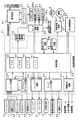
図4は、主基板31における回路構成の一例を示すブロック図である。なお、図4には、賞球制御基板37、ランプ制御基板35、音声制御基板70、発射制御基板91および表示制御基板80も示されている。主基板31には、プログラムに従ってパチンコ遊技機1を制御する基本回路53と、ゲートスイッチ12、始動口スイッチ17、Vカウントスイッチ22、カウントスイッチ23および入賞球検出スイッチ99からの信号を基本回路53に与えるスイッチ回路58と、可変入賞球装置15を開閉するソレノイド16および開閉板20を開閉するソレノイド21を基本回路53からの指令に従って駆動するソレノイド回路59と、始動記憶表示器18の点灯および滅灯を行うとともに7セグメントLEDによる可変表示器10と装飾ランプ25とを駆動するランプ・LED回路60とを含む。
【0032】
また、基本回路53から与えられるデータに従って、大当りの発生を示す大当り情報、可変表示部9の画像表示開始に利用された始動入賞球の個数を示す有効始動情報、確率変動が生じたことを示す確変情報等をホール管理コンピュータ等のホストコンピュータに対して出力する情報出力回路64を含む。
【0033】
基本回路53は、ゲーム制御用のプログラム等を記憶するROM54、ワークメモリとして使用されるRAM55、制御用のプログラムに従って制御動作を行うCPU56およびI/Oポート部57を含む。なお、ROM54,RAM55はCPU56に内蔵されている場合もある。
【0034】
さらに、主基板31には、電源投入時に基本回路53をリセットするための初期リセット回路65と、定期的(例えば、2ms毎)に基本回路53にリセットパルスを与えてゲーム制御用のプログラムを先頭から再度実行させるための定期リセット回路66と、基本回路53から与えられるアドレス信号をデコードしてI/Oポート部57のうちのいずれかのI/Oポートを選択するための信号を出力するアドレスデコード回路67とが設けられている。
なお、玉払出装置97から主基板31に入力されるスイッチ情報もあるが、図4ではそれらは省略されている。
【0035】
遊技球を打撃して発射する打球発射装置は発射制御基板91上の回路によって制御される駆動モータ94で駆動される。そして、駆動モータ94の駆動力は、操作ノブ5の操作量に従って調整される。すなわち、発射制御基板91上の回路によって、操作ノブ5の操作量に応じた速度で打球が発射されるように制御される。
【0036】
図5は、表示制御基板80内の回路構成を、可変表示部9の一実現例であるCRT82および主基板31の出力ポート(ポートA,B)571,572および出力バッファ回路63とともに示すブロック図である。出力ポート571からは表示制御コマンドデータが出力され、出力ポート572からはストローブ信号(INT信号)が出力される。
【0037】
表示制御用CPU101は、制御データROM102に格納されたプログラムに従って動作し、主基板31からノイズフィルタ107および入力バッファ回路105を介してストローブ信号が入力されると、入力バッファ回路105を介して表示制御コマンドを受信する。入力バッファ回路105として、例えば汎用ICである74HC244を使用することができる。なお、表示制御用CPU101がI/Oポートを内蔵していない場合には、入力バッファ回路105と表示制御用CPU101との間に、I/Oポートが設けられる。
【0038】
そして、表示制御用CPU101は、受信した表示制御コマンドに従って、CRT82に表示される画面の表示制御を行う。具体的には、表示制御コマンドに応じた指令をVDP103に与える。VDP103は、キャラクタROM86から必要なデータを読み出す。VDP103は、入力したデータに従ってCRT82に表示するための画像データを生成し、その画像データをVRAM87に格納する。そして、VRAM87内の画像データは、R,G,B信号に変換され、D−A変換回路104でアナログ信号に変換されてCRT82に出力される。
【0039】
なお、図5には、VDP103をリセットするためのリセット回路83、VDP103に動作クロックを与えるための発振回路85、および使用頻度の高い画像データを格納するキャラクタROM86も示されている。キャラクタROM86に格納される使用頻度の高い画像データとは、例えば、CRT82に表示される人物、動物、または、文字、図形もしくは記号等からなる画像などである。
【0040】
入力バッファ回路105は、主基板31から表示制御基板80へ向かう方向にのみ信号を通過させることができる。従って、表示制御基板80側から主基板31側に信号が伝わる余地はない。表示制御基板80内の回路に不正改造が加えられても、不正改造によって出力される信号が主基板31側に伝わることはない。なお、出力ポート571,572の出力をそのまま表示制御基板80に出力してもよいが、単方向にのみ信号伝達可能な出力バッファ回路63を設けることによって、主基板31から表示制御基板80への一方向性の信号伝達をより確実にすることができる。また、高周波信号を遮断するノイズフィルタ107として、例えば3端子コンデンサやフェライトビーズが使用されるが、ノイズフィルタ107の存在によって、表示制御コマンドに基板間でノイズが乗ったとしても、その影響は除去される。
【0041】
図6は、主基板31における音声制御コマンドの信号送信部分および音声制御基板70の構成例を示すブロック図である。この実施の形態では、遊技進行に応じて、遊技領域7の外側に設けられているスピーカ27の音声出力を指示するための音声制御コマンドが、主基板31から音声制御基板70に出力される。
【0042】
図6に示すように、音声制御コマンドは、基本回路53におけるI/Oポート部57の出力ポート(出力ポートC,D)573,574から出力される。出力ポート573からは音声制御コマンドデータが出力され、出力ポート574からはストローブ信号(INT信号)が出力される。音声制御基板70において、主基板31からの各信号は、入力バッファ回路705を介して音声制御用CPU701に入力する。なお、音声制御用CPU701がI/Oポートを内蔵していない場合には、入力バッファ回路705と音声制御用CPU701との間に、I/Oポートが設けられる。
【0043】
そして、例えばディジタルシグナルプロセッサによる音声合成回路702は、音声制御用CPU701の指示に応じた音声や効果音を発生し音量切替回路703に出力する。音量切替回路703は、音声制御用CPU701の出力レベルを、設定されている音量に応じたレベルにして音量増幅回路704に出力する。音量増幅回路704は、増幅した音声信号をスピーカ27に出力する。
【0044】
入力バッファ回路705として、例えば、汎用のCMOS−ICである74HC244が用いられる。74HC244のイネーブル端子には、常にローレベル(GNDレベル)が与えられている。よって、各バッファの出力レベルは、入力レベルすなわち主基板31からの信号レベルに確定している。よって、音声制御基板70側から主基板31側に信号が伝わる余地はない。従って、音声制御基板70内の回路に不正改造が加えられても、不正改造によって出力される信号が主基板31側に伝わることはない。なお、入力バッファ回路705の入力側にノイズフィルタを設けてもよい。
【0045】
また、主基板31において、出力ポート574,575の外側にバッファ回路67が設けられている。バッファ回路67として、例えば、汎用のCMOS−ICである74HC244が用いられる。イネーブル端子には常にローレベル(GNDレベル)が与えられている。このような構成によれば、外部から主基板31の内部に入力される信号が阻止されるので、音声制御基板70から主基板31に信号が与えられる可能性がある信号ラインをさらに確実になくすことができる。
【0046】
次に遊技機の動作について説明する。
図7は、主基板31における基本回路53の動作を示すフローチャートである。上述したように、この処理は、定期リセット回路66が発するリセットパルスによって、例えば2ms毎に起動される。CPU56が起動されると、CPU56は、まず、クロックモニタ制御を動作可能状態にするために、CPU56に内蔵されているクロックモニタレジスタをクロックモニタイネーブル状態に設定する(ステップS1)。なお、クロックモニタ制御とは、入力されるクロック信号の低下または停止を検出すると、CPU56の内部で自動的にリセットを発生する制御である。
【0047】
次いで、CPU56は、スタックポインタの指定アドレスをセットするためのスタックセット処理を行う(ステップS2)。この例では、スタックポインタに00FFHが設定される。そして、システムチェック処理を行う(ステップS3)。システムチェック処理では、CPU56は、RAM55にエラーが含まれているか判定し、エラーが含まれている場合には、RAM55を初期化するなどの処理を行う。
【0048】
次に、表示制御基板80に送出されるコマンドデータをRAM55の所定の領域に設定する処理を行った後に(表示制御データ設定処理:ステップS4)、コマンドデータを表示制御コマンドデータとして出力する処理を行う(表示制御データ出力処理:ステップS5)。
【0049】
次いで、各種出力データの格納領域の内容を各出力ポートに出力する処理を行う(データ出力処理:ステップS6)。また、ランプタイマを1減ずる処理を行い、ランプタイマがタイムアウトしたら(=0になったら)、ランプデータポインタを更新するとともに新たな値をランプタイマに設定する(ランプタイマ処理:ステップS7)。
【0050】
また、ランプデータポインタが示すアドレスのデータ、ホール管理用コンピュータに出力される大当り情報、始動情報、確率変動情報などの出力データを格納領域に設定する出力データ設定処理を行う(ステップS8)。さらに、パチンコ遊技機1の内部に備えられている自己診断機能によって種々の異常診断処理が行われ、その結果に応じて必要ならば警報が発せられる(エラー処理:ステップS9)。
【0051】
次に、遊技制御に用いられる大当り判定用乱数等の各判定用乱数を示す各カウンタを更新する処理を行う(ステップS10)。
図8は、各乱数を示す説明図である。各乱数は、以下のように使用される。
(1)ランダム1:大当りを発生させるか否か決定する(大当り決定用)
(2)ランダム2−1〜2−3:左右中のはずれ図柄決定用
(3)ランダム3:大当り時の図柄の組合せを決定する(大当り図柄決定用)
(4)ランダム4:はずれ時にリーチするか否か決定する(リーチ判定用)
(5)ランダム5:リーチの種類を決定する(リーチ種類決定用)
【0052】
なお、遊技効果を高めるために、上記(1)〜(5)の乱数以外の乱数も用いられている。
ステップS10では、CPU56は、(1)の大当り決定用乱数および(3)の大当り図柄判定用乱数を生成するためのカウンタのカウントアップ(1加算)を行う。すなわち、それらが判定用乱数である。
【0053】
次に、CPU56は、特別図柄プロセス処理を行う(ステップS11)。特別図柄プロセス制御では、遊技状態に応じてパチンコ遊技機1を所定の順序で制御するための特別図柄プロセスフラグに従って該当する処理が選び出されて実行される。そして、特別図柄プロセスフラグの値は、遊技状態に応じて各処理中に更新される。また、普通図柄プロセス処理を行う(ステップS12)。普通図柄プロセス処理では、7セグメントLEDによる可変表示器10を所定の順序で制御するための普通図柄プロセスフラグに従って該当する処理が選び出されて実行される。そして、普通図柄プロセスフラグの値は、遊技状態に応じて各処理中に更新される。
【0054】
さらに、CPU56は、スイッチ回路58を介して、各スイッチの状態を入力し、スイッチ状態に応じて必要な処理を行う(スイッチ処理:ステップS13)。また、後述するプロセスデータ中の音声データを音声制御基板70に送出する処理を行う(音声処理:ステップS14)。
【0055】
基本回路53は、さらに、表示用乱数を更新する処理を行う(ステップS15)。すなわち、ランダム2,4,5を生成するためのカウンタのカウントアップ(1加算)を行う。
【0056】
また、基本回路53は、賞球制御基板37との間の信号処理を行う(ステップS16)。すなわち、所定の条件が成立すると賞球制御基板37に賞球個数を示す賞球制御コマンドを出力する。賞球制御基板37に搭載されている賞球制御用CPUは、受信した賞球個数に応じて玉払出装置97を駆動する。
その後、基本回路53は、次に定期リセット回路66からリセットパルスが与えられるまで、ステップS17の表示用乱数更新処理を繰り返す。
【0057】
次に、始動入賞口14への入賞にもとづいて可変表示部9に可変表示される図柄の決定方法について図9〜図11のフローチャートを参照して説明する。図9は打球が始動入賞口14に入賞したことを判定する処理を示し、図10は可変表示部9の可変表示の停止図柄を決定する処理を示す。図11は、大当りとするか否か決定する処理を示すフローチャートである。
【0058】
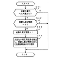
打球が遊技盤6に設けられている始動入賞口14に入賞すると、始動口センサ17がオンする。メイン処理のステップS11の特別図柄プロセス処理において、図9に示すように、CPU56は、スイッチ回路58を介して始動口センサ17がオンしたことを判定すると(ステップS41)、始動入賞記憶数が最大値である4に達しているかどうか確認する(ステップS42)。始動入賞記憶数が4に達していなければ、始動入賞記憶数を1増やし(ステップS43)、大当り図柄決定用乱数の値を抽出する。そして、それを始動入賞記憶数の値に対応した乱数値格納エリアに格納する(ステップS44)。なお、始動入賞記憶数が4に達している場合には、始動入賞記憶数を増やす処理を行わない。すなわち、この実施の形態では、最大4個の始動入賞口17に入賞した打球数が記憶可能である。
【0059】
また、CPU56は、ステップS11の特別図柄プロセス処理において、図10に示すように、始動入賞記憶数の値を確認する(ステップS50)。始動入賞記憶数が0でなければ、始動入賞記憶数=1に対応する乱数値格納エリアに格納されている値を読み出すとともに(ステップS51)、始動入賞記憶数の値を1減らし、かつ、各乱数値格納エリアの値をシフトする(ステップS52)。すなわち、始動入賞記憶数=n(n=2,3,4)に対応する乱数値格納エリアに格納されている値を、始動入賞記憶数=n−1に対応する乱数値格納エリアに格納する。
【0060】
そして、CPU56は、ステップS51で読み出した値、すなわち抽出されている大当り決定用乱数の値にもとづいて当たり/はずれを決定する(ステップS53)。ここでは、大当り決定用乱数は0〜299の範囲の値をとることにする。図11に示すように、低確率時には例えばその値が「3」である場合に「大当り」と決定し、それ以外の値である場合には「はずれ」と決定する。高確率時には例えばその値が「3」,「7」,「79」,「103」,「107」のいずれかである場合に「大当り」と決定し、それ以外の値である場合には「はずれ」と決定する。
【0061】
大当りと判定されたときには、CPU56は、大当り図柄決定用乱数の値にもとづいて大当り図柄(確定図柄)を決定する(ステップS62)。また、リーチ種類決定用乱数(ランダム5)を抽出しその値にもとづいてリーチ種類を決定する(ステップS57)。
【0062】
はずれと判定された場合には、CPU56は、リーチとするか否か判定する(ステップS58)。例えば、リーチ判定用の乱数であるランダム4の値が「105」〜「1530」のいずれかである場合には、リーチとしないと決定する。そして、リーチ判定用乱数の値が「0」〜「104」のいずれかである場合にはリーチとすることを決定する。リーチとすることを決定したときには、CPU56は、リーチ図柄の決定を行う。
【0063】
この実施の形態では、ランダム2−1の値に従って左右図柄を決定する(ステップS59)。また、ランダム2−2の値に従って中図柄を決定する(ステップS60)。すなわち、ランダム2−1およびランダム2−2の値の0〜15の値に対応したいずれかの図柄が停止図柄として決定される。ここで、決定された中図柄が左右図柄と一致した場合には、中図柄に対応した乱数の値に1加算した値に対応する図柄を中図柄の確定図柄として、大当り図柄と一致しないようにする。そして、リーチ種類決定用乱数(ランダム5)を抽出しその値にもとづいてリーチ種類を決定する(ステップS57)
【0064】
ステップS58において、リーチしないことに決定された場合には、ランダム2−1〜2−3の値に応じて左右中図柄を決定する(ステップS61)。なお、後述するように、この実施の形態では、高確率状態では、はずれ時の変動パターンとして変動時間が短縮されたものも使用される。そこで、高確率状態では、CPU56は、通常のはずれ時の変動パターンを用いるか短縮された変動パターンを用いるのかを、例えば所定の乱数等を用いて決定する。
【0065】
以上のようにして、始動入賞にもとづく図柄変動の表示態様を大当りとするか、リーチ態様とするか、はずれとするか決定され、それぞれの停止図柄の組合せが決定される。
【0066】
なお、高確率状態において、次に大当りとなる確率が上昇するとともに、7セグメントLEDによる可変表示器10の可変表示の確定までの時間が短縮され、かつ、可変表示器10の可変表示結果にもとづく当たり時の可変入賞球装置15の開放回数および開放時間が高められるようにパチンコ遊技機1が構成されていてもよいし、可変表示器10の可変表示結果にもとづく当たりの確率が高くなるように構成されていてもよい。また、それらのうちのいずれか一つまたは複数の状態のみが生ずるパチンコ遊技機1においても本発明は適用可能である。
【0067】
例えば、可変表示部9の停止図柄の組合せが特定図柄となった場合に、大当りとなる確率は上昇しないが可変表示器10の可変表示結果にもとづく当たり時の可変入賞球装置15の開放回数および開放時間が高められる遊技機においても、リーチとすることが決定されたら、左右の停止図柄を特定図柄の表示態様と一致させるか否か、すなわちどの図柄でリーチ状態を発生させるかが所定の乱数等の手段によって決定される遊技機においても本発明を適用可能である。
また、この実施の形態で用いられた乱数および乱数値の範囲は一例であって、どのような乱数を用いてもよいし、範囲設定も任意である。
【0068】
図12は、CPU56が実行する特別図柄プロセス処理のプログラムの一例を示すフローチャートである。図12に示す特別図柄プロセス処理は、図7のフローチャートにおけるステップS11の具体的な処理である。CPU56は、特別図柄プロセス処理を行う際に、その内部状態に応じて、図12に示すステップS300〜S309のうちのいずれかの処理を行う。各処理において、以下のような処理が実行される。
【0069】
特別図柄変動待ち処理(ステップS300):始動入賞口14(この実施の形態では可変入賞球装置15の入賞口)に打球入賞して始動口センサ17がオンするのを待つ。始動口センサ17がオンすると、始動入賞記憶数が満タンでなければ、始動入賞記憶数を+1するとともに大当り決定用乱数を抽出する。すなわち、図9に示された処理が実行される。
【0070】
特別図柄判定処理(ステップS301):特別図柄の可変表示が開始できる状態になると、始動入賞記憶数を確認する。始動入賞記憶数が0でなければ、抽出されている大当り決定用乱数の値に応じて大当りとするかはずれとするか決定する。すなわち、図10に示された処理の前半が実行される。
【0071】
停止図柄設定処理(ステップS302):左右中図柄の停止図柄を決定する。
すなわち、図10に示された処理の中半が実行される。
【0072】
リーチ動作設定処理(ステップS303):リーチ判定用乱数の値に応じてリーチ動作するか否か決定するとともに、リーチ用乱数の値に応じてリーチ態様の種類を決定する。すなわち、図10に示された処理の後半が実行される。
【0073】
全図柄変動開始処理(ステップS304):可変表示部9において全図柄が変動開始されるように制御する。このとき、表示制御基板80に対して、左右中最終停止図柄とリーチ態様を指令する情報とが送信される。また、可変表示部9に背景やキャラクタも表示される場合には、それに応じた表示制御コマンドデータが表示制御基板80に送出されるように制御する。
【0074】
全図柄停止待ち処理(ステップS305):変動期間が終了するのを待ち、変動期間が経過すると、可変表示部9において表示される全図柄を停止すべきことを示す全図柄停止コマンドが表示制御基板80に送出されるように制御する。
【0075】
大当り表示処理(ステップS306):停止図柄が大当り図柄の組み合わせである場合には、内部状態(プロセスフラグ)をステップS307に移行するように更新する。そうでない場合には、内部状態をステップS309に移行するように更新する。なお、大当り図柄の組み合わせは、左右中図柄が揃った組み合わせである。また、左右図柄が揃うとリーチとなる。
【0076】
大入賞口開放開始処理(ステップS307):大入賞口を開放する制御を開始する。具体的には、カウンタやフラグを初期化するとともに、ソレノイド21を駆動して大入賞口を開放する。
【0077】
大入賞口開放中処理(ステップS308):大入賞口ラウンド表示の表示制御コマンドデータが表示制御基板80に送出する制御や大入賞口の閉成条件の成立を確認する処理等を行う。大入賞口の閉成条件が成立したら、大当り遊技状態の終了条件が成立していなければ内部状態をステップS307に移行するように更新する。大当り遊技状態の終了条件が成立していれば、内部状態をステップS309に移行するように更新する。
【0078】
大当り終了処理(ステップS309):大当り遊技状態が終了したことを遊技者に報知するための表示を行う。その表示が終了したら、内部フラグ等を初期状態に戻し、内部状態をステップS300に移行するように更新する。
【0079】
上述したように、始動入賞口14に打球が入賞すると、基本回路53は、ステップS11(図7参照)の特別図柄プロセス処理において、大当りとするかはずれとするか、停止図柄およびリーチ態様を決定するが、その決定に応じた表示制御コマンドを表示制御基板80の表示制御用CPU101に与える。表示制御用CPU101は、主基板31からの表示制御コマンドに応じて可変表示部9の表示制御を行う。
【0080】
次に、図柄の変動を具体例を用いて説明する。
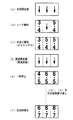
図13は、この実施の形態で用いられる左右中図柄の例を示す説明図である。
図13に示すように、この実施の形態では、左右中図柄として表示される各図柄は、左右中で同一の12図柄である。図柄番号12の図柄が表示されると、次に、図柄番号1の図柄が表示される。そして、左右中図柄が、例えば、「1」、「3」、「5」、「7」、「9」または「メロン」で揃って停止すると高確率状態となる。すなわち、それらが確変図柄となる。
【0081】
図14〜図17は、この実施の形態で用いられる主基板31から表示制御基板80に送信される図柄変動に関する表示制御コマンド例を示す説明図である。この例では、1つの表示制御コマンドは2バイト(CMD1,CMD2)で構成される。
【0082】
図14は、変動の態様および全図柄の停止を指示する表示制御コマンドを示す説明図である。図14に示すように、この例では、変動態様を特定可能な表示制御コマンドとして、「はずれ」、「確変時全図柄変動」、「リーチ1(再変動なし)」〜「リーチ5(再変動なし)」および「リーチ1(再変動あり)」〜「リーチ5(再変動あり)」がある。なお、リーチ1(再変動あり)〜リーチ5(再変動あり)の変動態様では、それぞれ、リーチ1(再変動なし)〜リーチ5(再変動なし)の変動態様に対して再変動期間を除いて同一の変動パターンが用いられる。
【0083】
なお、主基板31のCPU56は、図10に示されたステップS57の決定結果に応じて、リーチ1(再変動あり)〜リーチ5(再変動あり),リーチ1(再変動なし)〜リーチ5(再変動なし)のいずれかの表示制御コマンドを選択する。
【0084】
図15には、左図柄の停止図柄を示す表示制御コマンドが示されている。図15に示すように、2バイトの制御データCMD1,CMD2で構成される表示制御コマンドによって停止図柄が指定される。なお、それらの指定において、1バイト目の制御データCMD1の値は、「8B(H)」である。
【0085】
図16には、中図柄の停止図柄を示す表示制御コマンドが示されている。図16に示すように、2バイトの制御データCMD1,CMD2で構成される表示制御コマンドによって停止図柄が指定される。なお、それらの指定において、1バイト目の制御データCMD1の値は、「8C(H)」である。
【0086】
図17には、右図柄の停止図柄を示す表示制御コマンドが示されている。図17に示すように、2バイトの制御データCMD1,CMD2で構成される表示制御コマンドによって停止図柄が指定される。なお、それらの指定において、1バイト目の制御データCMD1の値は、「8D(H)」である。
【0087】
図18は、主基板31から表示制御基板80に送信される表示制御コマンドを示す説明図である。図18に示すように、この実施の形態では、表示制御コマンドは、表示制御信号CD0〜CD7の8本の信号線で主基板31から表示制御基板80に送信される。また、主基板31と表示制御基板80との間には、ストローブ信号を送信するための表示制御信号INTの信号線、表示制御基板80の電源となる+5V,+12Vの供給線、および接地レベルを供給するための信号線も配線されている。
【0088】
図19は、主基板31から遊技制御基板80に与えられる表示制御コマンドの送出タイミングの例を示すタイミング図である。この例では、表示制御コマンドデータを構成する2バイトの表示制御データは、図19に示すように、2ms毎に送出される。そして、各表示制御データに同期してストローブ信号(表示制御信号INT)が出力される。表示制御用CPU101には、ストローブ信号の立ち上がりで割込がかかるので、表示制御用CPU101は、割込処理プログラムによって各表示制御データを取り込むことができる。
【0089】
以下、図20〜図22を参照して図柄の変動パターンの例について説明する。
図20は、リーチとしないはずれ時の図柄の変動の一例を示すタイミング図である。また、図21は、リーチ時(大当りの場合および大当りとしない場合)の図柄の変動の一例を示すタイミング図である。そして、図22は、図柄の再変動を説明するための説明図である。
【0090】
この実施の形態では、はずれ時には、図20(A)に示すように、可変表示部9における「左」の図柄表示エリアにおいて、まず、パターンaに従って図柄の変動が行われる。パターンaは、少しずつ変動速度が上がるパターンである。その後、パターンbの一定速の高速変動が行われ、例えば停止図柄の3図柄前の図柄が表示されるように図柄差し替え制御された後、パターンcに従って3図柄の変動が行われる。パターンcは、徐々に遅くなって停止するパターンである。
【0091】
なお、表示制御基板80の表示制御用CPU101は、中図柄が確定するまで、左右図柄を変動方向の正方向と逆方向に繰り返し変動させる。すなわち、左右図柄を、いわゆる揺れ変動による停止状態に表示制御する。揺れ変動とは、図柄が上下に揺れる表示されることをいう。また、揺れ変動は、最終停止図柄(確定図柄)が表示されるまで行われる。従って、遊技者は、左右中図柄が最終停止するまで各図柄がまだ確定していないこと、すなわち、大当りの対象となる各図柄によって大当りが生ずる可能性があることを左右中図柄が最終停止するまで期待することができる。揺れ停止状態における揺れ変動は、図柄が上下に揺れるだけでなく、左右に揺れたりその他の方向に揺れるように制御されてもよい。
【0092】
そして、主基板31から全図柄停止を指示する表示制御コマンドを受信すると、左右図柄の揺れ変動状態を終了させて左右中図柄が動かない確定状態になる。なお、中図柄も、パターンcによる変動の後に揺れ動作を行い、その後確定状態になるようにしてもよい。
【0093】
表示制御用CPU101は、左右中の図柄表示エリアにおいて、指定された停止図柄で図柄変動が停止するように、所定のタイミングで停止図柄の3図柄前の図柄を表示制御する。変動開始時に左右中の停止図柄が通知され、かつ、はずれ時の変動パターンはあらかじめ決められているので、表示制御用CPU101は、パターンaからパターンbへの切替タイミングおよびパターンbからパターンcへの切替タイミングを認識することができるとともに、差し替えるべき3図柄前の図柄も決定できる。決定された差し替え図柄はVDP103に通知され、VDP103は、そのときに表示している図柄に関係なく、通知された図柄を表示する。
【0094】
図20(B)は、確率変動状態におけるはずれ時の変動パターンの一例を示す。この変動パターンでは、図に示されるように、パターンa、パターンbおよびパターンcに従って左右中図柄の変動が行われた後に、左右中図柄が同時に停止する。
【0095】
図21(A)は、中図柄によるリーチ動作が行われた後に左右中図柄が確定するリーチ態様、すなわち再変動なしの場合のリーチ態様を示す。図21(A)に示すように、左右図柄はパターンa,b,cによる変動が行われた後に停止する。このとき、左右図柄は同じ図柄で停止する。そして、中図柄があらかじめ決められたパターンで変動するリーチ動作が行われる。上述したように、この実施の形態では、リーチ1(再変動なし)〜リーチ5(再変動なし)の5種類の態様がある(図14参照)。それぞれの態様に応じて、リーチ動作の期間は異なっている。
【0096】
そして、主基板31から全図柄停止を指示する表示制御コマンドを受信すると、中図柄が停止し、左右中図柄が確定した状態になる。なお、中図柄が停止するまで、左右図柄を揺れ変動状態にしてもよい。
【0097】
図21(B)は、中図柄によるリーチ動作が行われた後に左右中図柄が一旦停止し、その後左右中図柄が再び変動を開始するリーチ態様、すなわち再変動ありの場合のリーチ態様を示す。再変動ありの変動パターンは、この実施の形態では、リーチ1(再変動あり)〜リーチ5の5種類(再変動あり)の5種類ある(図14参照)。
【0098】
リーチn(再変動あり)の変動開始からリーチ動作終了までの変動パターンはリーチn(再変動なし)の変動パターンと同じである(n=1〜5)。従って、図21(B)に示すタイミングA〜タイミングBまでの時間は、リーチ種類に応じて異なっている。しかし、リーチ動作終了(中図柄の一旦停止時:タイミングB)から再変動が終了して全図柄が確定するとき(タイミングC)までの時間は、常に一定に制御される。以下、タイミングB〜タイミングC間での期間を再抽選動作期間といい、再抽選動作期間において実際に図柄が変動している期間を再変動期間という。
【0099】
図22は、図21(B)に示された再変動ありの変動態様における画像表示例を示す説明図である。図22に示すように、左右中図柄が変動後((a)参照)、左右図柄が同じ図柄で停止してリーチ成立となる((b)参照)。その後、リーチ動作が行われ、中図柄も停止して大当りが確定する(タイミングB:(c)参照)。
【0100】
そして、この実施の形態では、左右中図柄は一旦停止(仮停止)するのであるが、表示制御用CPU101の制御によって、左右中図柄は、画面の端に小さく表示される((d)参照)。また、表示制御用CPU101は、画面の大部分を用いてキャラクタを運動表示することによって遊技演出を行う。特に、図22に例示されたように、最終停止図柄が確変図柄(この例では「7,7,7」)であり、仮停止図柄(一旦停止図柄)が非確変の大当たり図柄(この例では「4,4,4」)であるような場合に、キャラクタの動きによる演出によって非確変図柄が確変図柄に変化したかのように遊技者に感じさせることができる。
【0101】
なお、表示制御用CPU101は、背景の表示を制御することによって、また、背景およびキャラクタを制御することによって遊技演出を行ってもよい。
【0102】
そして、所定のタイミングが到来すると、左右中図柄を高速一定速で変動させ((e)参照)、確定図柄で停止させる((f)参照)。左右中の確定図柄は主基板31のCPU56から通知された図柄である。しかし、図22(c)に例示された仮停止図柄は、表示制御用CPU101によって決定される。
【0103】
すなわち、表示制御用CPU101は、乱数等を用いて仮停止図柄を決定する。例えば、乱数の生成範囲を1〜10に設定し、抽出された乱数値が確定図柄と仮停止図柄との差を示すものとすれば、仮停止図柄と最終停止図柄との差のコマ数が1〜10図柄となる10種類の変動パターンが存在することになる。この実施の形態では、再変動ありの変動態様としてリーチ1(再変動あり)〜リーチ5(再変動あり)の5種類があるので、結局、再変動ありの場合、50種類の変動パターンが存在することになる。
【0104】
しかし、主基板31のCPU56が扱う表示制御コマンドは、あくまで、リーチ1(再変動あり)〜リーチ5(再変動あり)の5種類である。つまり、変動パターンを増やしても、表示制御コマンドの数は増えず、主基板31のCPU56すなわち遊技制御手段の負担は増えない。再変動時の図柄変動数まで遊技制御手段が表示制御手段に通知するように構成した場合には、50種類の表示制御コマンドが必要になり、それだけ遊技制御手段の負担が増えてしまう。
【0105】
また、再変動期間を含むどの変動パターンでも大当りの確定から全図柄確定までの期間(再抽選動作期間)の長さは同じであるから、遊技制御手段は、再変動ありのリーチ態様を表示制御手段に指示した場合に、全図柄確定のタイミングを容易に識別することができる。
【0106】
表示制御コマンドの数を増やさず、かつ、表示制御手段の独自の制御によって再抽選動作期間の長さを可変にした場合には、遊技制御手段の負担は増えないものの、遊技制御手段が、全図柄確定のタイミングを認識することができなくなってしまう。よって、現実には、表示制御コマンドの数を増やさず、かつ、表示制御手段の独自の制御によって再抽選動作期間の長さを可変にすることはできない。しかし、この実施の形態のように、再抽選動作期間の長さを一定にした場合には、上述したように、遊技制御手段は全図柄確定のタイミングを認識できるので、表示制御コマンドの数を増やさずに変動の種類を増やすことができる。
【0107】
再抽選動作期間の長さを常に一定に保つために、表示制御手段は、例えば、再変動期間において図柄の差し替え制御を行う必要がある。例えば、再抽選動作期間が5秒で固定され、高速一定速の再変動期間が1.0秒である場合に、表示制御用CPU101は、再変動期間の終了時に表示図柄を最終停止図柄に差し替える。
【0108】
なお、この実施の形態では、リーチ1(再変動なし)〜リーチ5(再変動なし)およびリーチ1(再変動あり)〜リーチ5(再変動あり)のように、再変動ありの場合となしの場合とで別々の表示制御コマンドを用いるようにしたが、リーチ1〜リーチ5の表示制御コマンドと「再変動あり」の表示制御コマンドとを用いてもよい。その場合には、コマンド数は6種類に減る。
【0109】
なお、この実施の形態では、再抽選期間の長さを1種類としたが、2種類以上あってもよい。例えば、リーチ1(再変動あり)〜リーチ3(再変動あり)については再抽選期間を5秒で一定とし、リーチ4(再変動あり)〜リーチ5(再変動あり)については再抽選期間を8秒で一定とするような構成であってもよい。遊技機をそのように構成しても、遊技制御手段は、再変動ありのリーチ態様を表示制御手段に指示した場合に全図柄確定のタイミングを容易に識別することができるとともに、表示制御手段は、遊技制御手段から通知された最終停止図柄を変動期間の終了時に差し替え表示することによって、再抽選期間の長さを一定(5秒または8秒)にすることができる。
【0110】
以下、上述した再抽選動作期間を常に一定にした図柄変動を実現するための遊技制御手段および表示制御手段の動作を説明する。図23は、図12に示された特別図柄プロセス処理における全図柄変動開始処理(ステップS304)を示すフローチャートである。ステップS302,S303の停止図柄設定処理およびリーチ動作設定処理においてリーチ態様と停止図柄が決定されると、それらを指示するための表示制御コマンドの送出制御が行われるのであるが、ステップS304では、CPU56は、まず、コマンドの送出完了を待つ(ステップS304a)。なお、コマンド送出完了は、メイン処理(図7参照)中の表示制御データ出力処理(ステップS5)から通知される。
【0111】
この実施の形態では、CPU56は、図柄の変動を開始させるときに、図14に示されたコマンド[80(H),01(H)]〜[80(H),0C(H)]のいずれかを表示制御基板80に送出する。また、続けて、既に決定されている左右中の停止図柄(確定図柄)を示す表示制御コマンドを表示制御基板80に送出する。よって、ステップS304aのコマンド送信完了処理では、それら全てのコマンドの送出が完了したか否か確認される。なお、CPU56は、左右中の停止図柄を示す表示制御コマンドを送出してからコマンド[80(H),01(H)]〜[80(H),0C(H)]のいずれかを送出してもよい。
【0112】
表示制御コマンドの送出が完了すると、CPU56は、表示制御基板80に通知した変動時間を測定するための変動時間タイマをスタートする(ステップS304b)。そして、ステップS305に移行するように、特別図柄プロセスフラグを更新する(ステップS304c)。
【0113】
図24は、図12に示された特別図柄プロセス処理における全図柄停止待ち処理(ステップS305)を示すフローチャートである。ステップS305では、CPU56は、変動時間タイマがタイムアップしたか否か確認する(ステップS305a)。タイムアップしたら、全図柄停止を指示する表示制御コマンドを設定する(ステップS305b)。そして、表示制御コマンドデータ送出要求をセットし(ステップS305c)、ステップS306に移行するように、特別図柄プロセスフラグを更新する(ステップS305d)。なお、表示制御コマンドデータ送出要求は、メイン処理(図7参照)中の表示制御データ設定処理(ステップS3)で参照される。
【0114】
以上のように、特別図柄プロセス処理において、CPU56は、変動の開始時に変動態様を特定可能な情報と停止図柄を指示する情報とを表示制御基板80に送出する。そして、変動時間タイマがタイムアップしたら、すなわち指示した変動態様に応じた時間が終了したら、全図柄変動を指示する情報を表示制御基板80に送出する。その間、CPU56は、表示制御基板80に表示制御コマンドを送出しない。従って、主基板31のCPU56の表示制御に要する負荷は大きく低減されている。
【0115】
図25は、表示制御データ設定処理(図7に示されたメイン処理におけるステップS4)の動作例を示すフローチャートである。表示制御データ設定処理において、CPU56は、まず、データ送出中フラグがセットされているか否か確認する(ステップS411)。セットされていなければ、表示制御コマンドデータの送出要求フラグがセットされているか否か確認する(ステップS412)。送出要求フラグがセットされていれば、送出要求フラグをリセットする(ステップS413)。また、送出すべき表示制御コマンドデータを出力データ格納領域に設定するとともに(ステップS414)、ポート出力要求をセットする(ステップS416)。なお、表示制御コマンドデータの送出要求フラグは、特別図柄プロセス処理においてセットされる。また、データ送出中フラグは、後述する表示制御データ出力処理においてセットされる。
【0116】
図26は、図7に示されたメイン処理における表示制御データ出力処理(ステップS5)を示すフローチャートである。表示制御データ出力処理において、CPU56は、ポート出力要求がセットされているか否か判定する(ステップS421)。ポート出力要求がセットされている場合には、ポート出力要求をリセットし(ステップS422)、ポート格納領域の内容(表示制御コマンドの1バイト目)を出力ポート571に出力する(ステップS423)。そして、ポート出力カウンタを+1する(ステップS424)。さらに、INT信号をローレベル(オン状態)にし(ステップS425)、データ送出中フラグをオンする(ステップS426)。
【0117】
ポート出力要求がセットされていない場合には、ポート出力カウンタの値が0であるか否か判定する(ステップS431)。ポート出力カウンタの値が0でない場合には、ポート出力カウンタの値が1であるか否か確認する(ステップS432)。ポート出力カウンタの値が1である場合には、表示制御コマンドの1バイト目に関するINT信号オフタイミングになっているので、INT信号をオフ(=1)にする(ステップS433)。また、ポート出力カウンタの値を1増やす(ステップS434)。
【0118】
ポート出力カウンタの値が2である場合には(ステップS435)、表示制御コマンドの2バイト目の出力タイミングになっているので、ポート格納領域の内容(表示制御コマンドの2バイト目)を出力ポート571に出力する(ステップS436)。そして、ポート出力カウンタを+1する(ステップS437)。さらに、INT信号をローレベルにする(ステップS438)。
【0119】
そして、ポート出力カウンタの値が2でない場合には、すなわち3である場合には、表示制御コマンドの2バイト目に関するINT信号オフタイミングになっているので、ポート出力カウンタの値をクリアするとともに(ステップS441)、INT信号をオフ(ハイレベル)にする(ステップS442)。また、データ送出中フラグをオフする(ステップS443)。
【0120】
この実施の形態では、図26に示された表示制御データ出力処理は2msに1回実行される。従って、図26に示されたデータ出力処理によって、図19に示されたように、2ms毎に1バイトのデータが出力される。
【0121】
次に、表示制御用CPU101の動作を説明する。
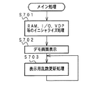
図27は、表示制御用CPU101のメイン処理を示すフローチャートである。メイン処理では、表示制御用CPU101は、まず、RAM、I/OポートおよびVDP103等を初期化する(ステップS701)。そして、可変表示部9にデモンストレーション画面が出現するように表示制御する(ステップS702)。その後、表示用乱数更新処理(表示用乱数を生成するカウンタの更新処理)を繰り返し実行する(ステップS703)。表示制御用CPU101が扱う表示用乱数として、例えば、再抽選動作期間前の仮停止図柄を決定するための乱数がある。
【0122】
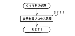
この実施の形態では、実際の変動制御等は、タイマ割込処理によって行われる。タイマ割込は、例えば2ms毎に発生する。図28に示すように、タイマ割込処理では、表示制御用CPU101は、表示制御プロセス処理(ステップS711)を実行する。表示制御プロセス処理では、表示制御プロセスフラグの値に応じた表示制御処理が行われる。
【0123】
主基板31からの表示制御コマンドは、IRQ2割込によって表示制御用CPU101に受信される。図29は、表示制御用CPU101のIRQ2割込処理を示すフローチャートである。IRQ2割込処理において、表示制御用CPU101は、まず、データ受信中フラグがセットされているか否か確認する(ステップS601)。セットされていなければ、この割込が表示制御コマンドデータにおける第1バイトの表示制御データ送出による割込である。そこで、ポインタをクリアするとともに(ステップS602)、データ受信中フラグをセットする(ステップS603)。そして、ステップS604に移行する。ポインタは、表示制御用CPU101が内蔵しているRAMにおける表示制御コマンドデータ格納エリアにおける何バイト目に受信データを格納するか指し示すものである。
【0124】
データ受信中フラグがセットされている場合には、ストローブ信号がオフしたら(ステップS604)、表示制御用CPU101は、入力ポートからデータを入力し、表示制御コマンドデータ格納エリアにおいてポインタによって示されているアドレスに、入力データを格納する(ステップS605)。
【0125】
そして、表示制御用CPU101は、ポインタの値を+1する(ステップS606)。そして、ポインタの値が2になった場合には(ステップS607)、2バイトで構成される表示制御コマンドデータの受信が完了したことになるので、データ受信完了フラグをセットするとともに、データ受信中フラグをリセットする(ステップS608,S609)。以上のような処理によって、表示制御データCMD1,CMD2が、表示制御基板80において受信される。
【0126】
図30は、図28に示されたタイマ割込処理における表示制御プロセス処理(ステップS711)を示すフローチャートである。表示制御プロセス処理では、表示制御プロセスフラグの値に応じてステップS720〜S870のうちのいずれかの処理が行われる。各処理において、以下のような処理が実行される。
【0127】
表示制御コマンド受信待ち処理(ステップS720):IRQ2割込処理によって、変動態様を特定可能な表示制御コマンドを受信したか否か確認する。
【0128】
仮停止図柄決定処理(ステップS750):再変動を行う場合に、再抽選前の仮停止図柄を決定する。
【0129】
全図柄変動開始処理(ステップS780):左右中図柄の変動が開始されるように制御する。
【0130】
図柄変動中処理(ステップS810):変動パターンを構成する各変動状態(変動速度や背景、キャラクタ)の切替タイミングを制御するとともに、変動時間の終了を監視する。また、左右図柄の停止制御や再抽選制御を行う。
【0131】
全図柄停止待ち設定処理(ステップS840):変動時間の終了時に、全図柄停止を指示する表示制御コマンドを受信していたら、図柄の変動を停止し最終停止図柄(確定図柄)を表示する制御を行う。
【0132】
大当り表示処理(ステップS870):変動時間の終了後、確変大当り表示または通常大当り表示の制御を行う。
【0133】
図31は、表示制御コマンド受信待ち処理(ステップS720)を示すフローチャートである。表示制御コマンド受信待ち処理において、表示制御用CPU101は、まず、変動態様を特定可能な表示制御コマンドを受信したか否か確認する(ステップS721)。変動態様を特定可能な表示制御コマンドは、図14に示されたコマンド[80(H),01(H)]〜[80(H),0C(H)]のいずれかである。変動態様を特定可能な表示制御コマンドを受信した場合には、表示制御プロセスフラグの値を仮停止図柄決定処理(ステップS750)に対応した値に変更する(ステップS722)。
【0134】
なお、主基板31から表示制御基板80に最初に送信される表示制御コマンドは、変動態様を示すコマンドと左右中図柄の停止図柄を指定するコマンドであるが、それらは、表示制御データ格納エリアに格納されている(図29におけるステップS605参照)。
【0135】
図32は、仮停止図柄決定処理(ステップS750)を示すフローチャートである。仮停止図柄決定処理において、表示制御用CPU101は、まず、変動態様を特定可能な表示制御コマンドから、リーチにもならないはずれか否か判断する(ステップS751)。具体的には、コマンドA0またはA2を受信していたらはずれである。
【0136】
はずれであるならば、主基板31から通知された左右の停止図柄が異なっているものであるか否か確認する(ステップS752)。一致していた場合には、右停止図柄を1図柄ずらしたものとする(ステップS753)。そして、左右中の停止図柄を所定の記憶エリアに格納する(ステップS754)。また、監視タイマに7.9秒を設定する(ステップS752)。7.9秒は、はずれ時の変動時間7.8秒に対して余裕を持たせた値であり、監視タイマがタイムアウトする前に全図柄停止を指定するコマンドを受信できなかったときには所定の処理が行われる。
【0137】
ステップS751において、はずれでなかったら、すなわち、コマンド[80(H),03(H)]〜[80(H),0C(H)]のいずれかを受信していたら、左右の停止図柄が同一か否か確認する(ステップS756)。異なっていた場合には、右停止図柄を左停止図柄と同じものにする(ステップS757)。そして、左右中の停止図柄を所定の記憶エリアに格納する(ステップS754)。また、表示制御用CPU101は、コマンド[80(H),03(H)]〜[80(H),0C(H)]に応じた変動時間に0.1秒を加算した値を監視タイマに設定する(ステップS759)。
【0138】
また、主基板31から再変動ありの変動態様を通知されていたら、すなわち、コマンド[80(H),08(H)]〜[80(H),0C(H)]を受信していたら(ステップS760)、所定の乱数にもとづいて仮停止図柄を決定する(ステップS761)。
【0139】
以上のように、この実施の形態では、表示制御用CPU101は、可変表示を開始させる際に主基板31から送出されたコマンド[80(H),01(H)]〜[80(H),0C(H)]と受信した左右中停止図柄とが矛盾しているときには停止図柄を補正する。従って、何らかの原因で左右中停止図柄に誤りが生じたととしてもその誤りは是正される。誤りとは、例えば、主基板31から表示制御基板80に至るケーブルにノイズが乗ってコマンドにビット誤りが生じたような場合である。この結果、遊技制御手段が決定したはずれ/リーチと矛盾するような確定図柄の表示がなされることが防止される。
【0140】
次いで、表示制御用CPU101は、変動態様に応じたプロセステーブルを使用することを決定する(ステップS763)。各プロセステーブルには、その変動態様中の各変動状態(変動速度やその速度での変動期間等)が設定されている。また、各プロセステーブルはROMに設定されている。そして、表示制御用CPU101は、表示制御プロセスフラグの値を全図柄変動開始処理(ステップS780)に対応した値に変更する(ステップS764)。
【0141】
図33は、プロセステーブルの構成例を示す説明図である。それぞれの変動態様に対応した各プロセステーブルには、時系列的に、変動速度やその速度での変動期間、背景やキャラクタの切替タイミング等の図柄変動データが設定されている。また、ある速度での変動期間を決めるためのプロセスタイマ値も設定されている。また、各プロセステーブルは、複数の3バイト単位のプロセスデータで構成され、3バイト中の2バイトがプロセスタイマ値として用いられ1バイトが図柄変動データとして用いられている。なお、1バイトでは全ての図柄変動データを表現できない場合には、プロセステーブルのサイズが例えば4バイトとされる。
【0142】
表示制御用CPU101は、プロセスタイマのタイムアップによって何らかの表示状態を変更しなければならないことを知ることができる。そして、変更すべき表示状態は、プロセステーブルにおける次のプロセスデータの3バイト目の設定値から知ることができる。
【0143】
一例として、図34に、図21(B)に示された変動パターンが使用される場合のプロセステーブルの構成例を示す。表示制御用CPU101は、図柄の変動開始時に、まず、左右中図柄を低速で変動させるようにV103DPを制御する。そして、プロセステーブルの最初に((1)に)設定されているプロセスタイマ値でタイマをスタートさせる。タイマがタイムアップすると、(1)の図柄変動データに設定されている制御内容でVDP103の制御状態を変更するとともに、(2)のプロセスタイマ値でタイマをスタートさせる。タイマがタイムアップすると、(2)の図柄変動データに設定されている制御内容でVDP103の制御状態を変更するとともに、(3)のプロセスタイマ値でタイマをスタートさせる。
【0144】
そして、タイマがタイムアップすると、(3)の図柄変動データに設定されている制御内容でVDP103の制御状態を変更するとともに、(4)のプロセスタイマ値でタイマをスタートさせる。この段階で、左右中図柄は、パターンaの変動態様において変動速度が一段上昇したことになる。
【0145】
以下、タイマがタイムアップしたら図柄変動データにもとづく制御状態の変更を行うとともに、プロセステーブルにおける次のプロセスタイマ値を用いてタイマをスタートさせる。従って、左右中の全ての図柄がパターンbによる高速変動状態に入ってから((9)に対応)、4.2秒が経過すると、左図柄の変動状態をパターンcによるものとするために、左図柄の変動速度を中速にするように制御状態を変更する((10)に対応)。
【0146】
(11)〜(13)のプロセスタイマがタイムアウトすると、リーチ確定となる。その後、リーチ動作中の各変動パターンに対応したプロセスタイマが順次スタートされ(図34では省略)、(14)のプロセスタイマがタイムアウトすると、大当り確定となって左右中の仮停止図柄が停止表示される。
【0147】
さらに、左右中図柄の仮停止期間を設定するためのプロセスタイマがスタートされ((15)に対応)、プロセスタイマがタイムアウトすると、再変動期間を設定するためのプロセスタイマがスタートされる((16)に対応)。そして、プロセスタイマがタイムアウトすると、表示制御用CPU101は、左右中図柄を最終停止させる制御を行う。
【0148】
なお、プロセステーブルには、さらに、背景およびキャラクタの切り替えタイミングも含まれるが、図34では、再抽選動作期間におけるキャラクタに関するデータ以外は省略されている。
【0149】
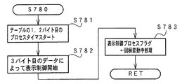
図35は、全図柄変動開始処理(ステップS780)を示すフローチャートである。全図柄変動開始処理において、表示制御用CPU101は、使用することが決定されたプロセステーブルの最初に設定されているプロセスタイマ値でタイマをスタートさせる(ステップS781)。また、3バイト目に設定されている変動状態を示すデータにもとづいて図柄変動制御、背景およびキャラクタの表示制御を開始する(ステップS782)。そして、表示制御プロセスフラグの値を図柄変動中処理(ステップS810)に対応した値に変更する(ステップS783)。
【0150】
図36は、図柄変動中処理(ステップS810)を示すフローチャートである。図柄変動中処理において、表示制御用CPU101は、プロセスタイマがタイムアウトしたか否か確認する(ステップS811)。プロセスタイマがタイムアウトした場合には、プロセステーブル中のデータを示すポインタを+3する(ステップS812)。そして、ポインタが指す領域のデータが終了コードであるか否か確認する(ステップS813)。終了コードでなければ、ポインタが指すプロセスデータの3バイト目に設定されている変動状態を示すデータにもとづいて図柄変動制御、背景およびキャラクタの表示制御を変更するとともに(ステップS814)、1,2バイト目に設定されているプロセスタイマ値でタイマをスタートさせる(ステップS815)。
【0151】
ステップS813で、終了コードであれば、表示制御プロセスフラグの値を全図柄停止待ち処理(ステップS840)に対応した値に変更する(ステップS816)。
【0152】
図37は、全図柄停止待ち処理(ステップS840)を示すフローチャートである。全図柄停止待ち処理において、表示制御用CPU101は、全図柄停止を指示する表示制御コマンドを受信しているか否か確認する(ステップS841)。全図柄停止を指示する表示制御コマンドを受信していれば、記憶されている停止図柄で図柄を停止させる制御を行う(ステップS842)。そして、次の表示制御コマンドの受信までの時間を監視するために、コマンド無受信タイマをスタートさせる(ステップS843)。
【0153】
全図柄停止を指定する表示制御コマンドを受信していない場合には、監視タイマがタイムアウトしているかどうか確認する(ステップS845)。タイムアウトした場合には、何らかの異常が発生したと判断して、可変表示部9にエラー画面を表示する制御を行う(ステップS846)。
【0154】
ステップS843の処理を行ったら、表示制御用CPU101は、表示制御プロセスフラグの値を大当り表示処理(ステップS870)に対応した値に設定する(ステップS844)。
【0155】
以上のように、この実施の形態では、可変表示部9に可変表示される図柄の変動態様と停止図柄を特定可能な情報を遊技制御手段すなわち主基板31のCPU56から表示制御手段に送出し、表示制御手段が、図柄変動に関わらない背景やキャラクタの表示および表示切替を制御する。従って、1回の図柄変動について遊技制御手段から表示制御手段に送出される表示制御コマンドの数が低減されている。
【0156】
そして、遊技制御手段は変動期間が終了した時点で全図柄停止を示す表示制御コマンドを表示制御手段に与え、表示制御手段は、全図柄停止を示す表示制御コマンドによって図柄を確定する。従って、図柄は、遊技制御手段が管理するタイミングで確実に確定する。この実施の形態のように、遊技制御手段が図柄の変動開始に関連する時点で変動時間を特定可能な情報と停止図柄に関する情報を送信し、その後、表示制御手段が独自に変動パターンを決めたり図柄の差し替え制御等を行ったりする場合には、表示制御のかなりの部分が表示制御手段によって実行されていることになる。
【0157】
すると、遊技制御手段は具体的な変動パターンを認識できないので、何らの対策も施さないと、遊技制御手段が決定した変動時間とずれた変動が行われているおそれもある。しかし、遊技制御手段が変動期間が終了した時点で全図柄停止を示す表示制御コマンドを表示制御手段に与えるように構成すれば、遊技制御手段が決定した変動時間の終了時に図柄は確実に確定する。また、全図柄停止を指示する表示制御コマンドが受信できない場合にエラー表示を行うようにすれば、異常が生じたことは直ちに認識される。
【0158】
さらに、この実施の形態では、再抽選期間を含む場合には、仮停止図柄に対する最終停止図柄の図柄変化数がいくつであっても再抽選期間は同一である。従って、遊技制御手段は、再変動ありのリーチ態様を表示制御手段に指示した場合に、全図柄確定のタイミングを容易に識別することができる。よって、遊技制御手段は、再変動期間における変化コマ数(仮停止図柄と最終停止図柄との差)に応じた数の表示制御コマンドを扱わなくてもよい。すなわち、遊技制御手段は、リーチ態様の種類に応じた数の表示制御コマンドを扱うだけでよく、再変動期間における変化コマ数の種類が多くても、遊技制御手段の可変表示に関する制御負荷が増大することはない。なお、すでに述べたように、期間長が一定である再抽選期間は1種類でもよいが多種類でもよい。
【0159】
また、図22に示されたように、再抽選動作期間において、図柄の変動が一旦停止する仮停止期間が設けられ、その期間では、表示制御用CPU101およびVDP103は、可変表示部9における左右中図柄の表示領域を小さくし、かつ、可変表示部9の端に寄せる。そして、可変表示部9における広い領域において、キャラクタを運動表示したり背景を変化させるような表示を行う。よって、再抽選期間における再変動が単純な高速一定速であっても、遊技者は、キャラクタや背景の変化によって、より大きな期待感を抱く。このとき、左右中図柄は小さく表示されているので、キャラクタや背景による演出を阻害することはない。
【0160】
なお、この実施の形態では、再抽選動作期間において、再変動開始前では左右中図柄を仮停止させるようにしたが、その期間でも、高速変動させるようにしてもよい。そのような制御を行っても、キャラクタや背景の変化による再抽選動作の演出を図柄が阻害することはない。
【0161】
また、再変動期間では左右中図柄を高速変動させ、期間経過時に直ちに図柄を最終停止させるので、再変動期間における図柄可変表示制御は容易である。なお、再変動期間をなくして、仮停止図柄から直ちに最終停止図柄に差し替えるような表示制御を行っても効果的である。
【0162】
図38は、再変動ありの場合のリーチ態様の他の例(第2の実施の形態)を示すタイミング図である。この例でも、リーチ動作終了(中図柄の一旦停止時:タイミングB)から再変動が終了して全図柄が確定するとき(タイミングC)までの時間は、常に一定に制御される。ただし、この例では、再抽選動作期間において、まず、図柄の再変動が行われ、仮停止期間をおいて再度再変動が行われた後に図柄は最終停止する。
【0163】
図39は、図38に示された第2の実施の形態における図柄変動例を示す説明図である。図38に示されたような変動態様は、画像表示可能なCRTやLCDのような可変表示部9によっても実現可能であるが、ドラム式の可変表示部でも可能である。よって、図39には、ドラム式の可変表示部に可変表示される図柄の例が示されている。なお、ドラム式の可変表示部を用いた場合にも、表示制御用CPUが設けられ、表示制御用CPUは、主基板31のCPU56から表示制御コマンドを受信し、受信した表示制御コマンドに応じた図柄変動制御を行う。
【0164】
図39に示すように、左右中図柄が変動後((a)参照)、左右図柄が同じ図柄で停止してリーチ成立となる((b)参照)。その後、中図柄変動によるリーチ動作が行われ、中図柄も停止して大当りが確定する(タイミングB:(c)参照)。そして、この実施の形態では、再抽選動作期間において、左右中図柄は再変動してから仮停止するのであるが((d),(e)参照)、仮停止時に、表示制御用CPUは、中図柄を上下に揺らすように制御する((e)参照)。すなわち、中図柄のリールを駆動するモータの順方向回転と逆方向回転を繰り返すように制御する。
【0165】
また、このとき、表示制御用CPUは、表示部に、確変図柄によるリーチおよび非確変図柄によるリーチが成立したように図柄表示を行う((e)参照)。さらに、確変状態に突入させる場合には、確変図柄の組み合わせを遊技者に対して表示する((f)参照)。その後、左右中図柄が再変動してから((g)参照)、左右中図柄は最終停止する((h)参照)。
【0166】
この例でも、再抽選動作期間(図39における(c)〜(h))は常に一定に制御される。また、図39(c)に例示された仮停止図柄は、表示制御用CPUによって所定の乱数等にもとづいて決定される。よって、表示制御用CPUは、決定した仮停止図柄で図38に示されたタイミングBにおいて左右中図柄を仮停止させるために、図柄変動の速度調整を行う必要がある。例えば、図38に示されたタイミングAからリーチ確定までの間における高速変動期間において、変動速度すなわち図柄リールを駆動するモータの回転速度を、所定の速度に対して上げたり下げたりする。
【0167】
また、表示制御用CPUは、再抽選動作期間の長さを一定にするために、仮停止図柄と確定図柄との差のコマ数に応じて、図柄再変動期間における変動速度を調整する。例えば、差のコマ数が多い場合には変動速度を速くし(モータの回転速度を速くし)、差のコマ数が少ない場合には、変動速度を遅くすればよい。
【0168】
第2の実施の形態では、再抽選動作期間において、確変図柄と非確変図柄の表示を組み合わせることによって遊技者の期待感を向上させる。よって、上述した第1の実施の形態のようにキャラクタや背景によって再抽選動作期間における遊技者の期待感を向上させる場合に比べて、表示制御は簡単である。
【0169】
なお、この実施の形態ではドラム式の可変表示部を用いた場合について説明したが、画像表示式の可変表示部9を用いても同様の表示制御を行うことができる。また、画像表示式の可変表示部9を用いた場合には、再抽選期間における再変動期間で、図柄変動を直ちに高速一定速変動とすることもできる。可変表示部が画像表示式である場合には、変動期間において速度調整制御を行わず、変動期間の最後に所定の図柄を差し替え表示することによって、変動期間における変動速度を常に同じにしても一定の再抽選動作期間を実現することができる。
【0170】
図40は、再変動ありの場合のリーチ態様のさらに他の例(第3の実施の形態)を示すタイミング図である。この例でも、リーチ動作終了(中図柄の一旦停止時:タイミングB)から再変動が終了して全図柄が確定するとき(タイミングC)までの時間は、常に一定に制御される。この例では、再抽選動作期間において、左右中図柄が一致した状態でコマ送り変動が行われた後に図柄は最終停止する。
【0171】
図41は、図40に示された第3の実施の形態における図柄変動例を示す説明図である。図41に示すように、左右中図柄が変動後((a)参照)、左右図柄が同じ図柄で停止してリーチ成立となる((b)参照)。その後、中図柄変動によるリーチ動作が行われ、中図柄も停止して大当りが確定する(タイミングB:(c)参照)。そして、この実施の形態では、再抽選動作期間において、コマ送り変動が行われた後に((d)参照)、左右中図柄は最終停止する((e)参照)。
【0172】
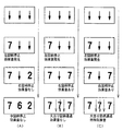
この実施の形態では、再抽選動作期間における送りコマ数は常に一定にされる。図40に示された例では、常に送りコマ数は5とされる。ただし、表示制御用CPU101は、常に順序よく図柄を可変表示するのではなく、図42に例示するように、図柄をランダムにコマ送り表示する。図42に示す各例では、いずれも、最終停止図柄は「7,7,7」であり仮停止図柄は「4,4,4」であるが、途中の表示図柄が異なっている。なお、第1の実施の形態と同様に、仮停止図柄は、例えば表示制御用CPU101によって乱数等にもとづいて決定される。
【0173】
この実施の形態では、再抽選動作期間の長さを一定に保つことは容易である。
ただし、表示制御用CPU101は、ランダムな図柄変動を行うために、例えば、所定の乱数等にもとづいて図柄表示順を決定する。そして、1コマ分の送り時間が経過すると、VDP103に対して次に図柄を表示することを指示する。以上のように、ランダムな図柄変動は表示制御用CPU101によって実現される。よって、このような図柄変動を行う場合でも、遊技制御手段の負担が増加することはない。
【0174】
図43は、再変動ありの場合のリーチ態様のさらに他の例(第4の実施の形態)を示すタイミング図である。この例でも、リーチ動作終了(中図柄の一旦停止時:タイミングB)から再変動が終了して全図柄が確定するとき(タイミングC)までの時間は、常に一定に制御される。ただし、この例では、再抽選動作期間において、一時停止と図柄の高速変動とを含む変動パターンが所定回(1回以上)繰り返された後に図柄は最終停止する。
【0175】
図44は、図43に示された第4の実施の形態における図柄変動例を示す説明図である。図43に示されたような変動態様は、画像表示可能なCRTやLCDのような可変表示部9によっても実現可能であるが、ドラム式の可変表示部でも可能である。よって、図44には、ドラム式の可変表示部に可変表示される図柄の例が示されている。図44に示すように、左右中図柄が変動後((a)参照)、左右図柄が同じ図柄で停止してリーチ成立となる((b)参照)。その後、中図柄変動によるリーチ動作が行われ、中図柄も停止して大当りが確定する(タイミングB:(c)参照)。
【0176】
そして、この実施の形態では、再抽選動作期間において、一時停止期間がおかれた後に、高速再変動が行われる((d)参照)。また、一時停止期間および高速再変動が所定回繰り返された後に((e)参照)、左右中図柄は最終停止する((f)参照)。
【0177】
第4の実施の形態でも、再抽選動作期間(図44における(c)〜(f))は常に一定に制御される。また、図44(c)に例示された仮停止図柄は、各図柄リールを制御する表示制御用CPUによって所定の乱数等にもとづいて決定される。よって、表示制御用CPUは、決定した仮停止図柄で図43に示されたタイミングBにおいて左右中図柄を仮停止させるために、図柄変動の速度調整を行う必要がある。例えば、図43に示されたタイミングAからリーチ確定までの間における高速変動期間において、変動速度すなわち図柄リールを駆動するモータの回転速度を、所定の速度に対して上げたり下げたりする。
【0178】
また、再抽選動作期間の長さを一定にするために、仮停止図柄と確定図柄との差のコマ数に応じて、図柄再変動期間における変動速度を調整する。例えば、差のコマ数が多い場合には任意の1つまたは複数の再変動期間における変動速度を速くし(モータの回転速度を速くし)、差のコマ数が少ない場合には、任意の1つまたは複数の再変動期間における変動速度を遅くすればよい。
【0179】
第4の実施の形態では、再抽選動作期間において、図柄の一時停止と高速変動とを組み合わせることによって遊技者の期待感を向上させる。よって、キャラクタや背景によって再抽選動作期間における遊技者の期待感を向上させる場合に比べて、表示制御は簡単である。そして、このような図柄変動制御を行う場合でも、仮停止図柄の決定および再抽選動作期間の長さを一定に保つための制御は表示制御用CPUによって実行される。よって、遊技制御手段の負担が重くなることはない。
【0180】
なお、この実施の形態ではドラム式の可変表示部を用いた場合について説明したが、画像表示式の可変表示部9を用いても同様の表示制御を行うことができる。可変表示部が画像表示式である場合には、変動期間における速度調整制御を行わず、変動期間の最後に所定の図柄を差し替え表示することによって、変動期間における変動速度を常に同じにしても一定の再抽選動作期間を実現することができる。また、再抽選動作期間において図柄の一時停止と高速変動とがそれぞれ1回実行される変動パターンを用いてもよい。
【0181】
以上のように、第3の実施の形態では、大当り時に大当り図柄とは異なる図柄を一旦仮停止表示し、その後に最終的な図柄を確定表示することが可能な遊技機において、表示制御手段が、図柄コマ送りによる再抽選動作期間の長さを一定にするとともに、送りコマ数を常に一定とし、コマ送り順をランダムにするように決定するので、遊技制御手段が扱う表示制御コマンド数を増やさずに豊富な再抽選動作を行うことができるとともに、簡易な表示制御によって再抽選動作期間における遊技者の期待感を向上させることができる。
【0182】
また、第4の実施の形態では、大当り時に大当り図柄とは異なる図柄を一旦仮停止表示し、その後に最終的な図柄を確定表示することが可能な遊技機において、表示制御手段が、再抽選動作期間の長さを一定にするとともに、再抽選動作期間では図柄の一時停止と高速再変動とを1回以上行うので、やはり、遊技制御手段が扱う表示制御コマンド数を増やさずに豊富な再抽選動作を行うことができるとともに、簡易な表示制御によって再抽選動作期間における遊技者の期待感を向上させることができる。
【0183】
上記の各実施の形態では、再抽選期間における図柄等による遊技演出に着目したが、図柄の変動開始から大当りの確定までの間で、スピーカ27から発せられる効果音によって遊技者の期待感を向上させてもよい。
【0184】
図45は、そのような実施の形態における図柄表示例を示す説明図である。図45(A)に示された例ははずれとなる場合の図柄表示例である。図45(A)に示すように、左図柄停止時に、スピーカ27から効果音(例えば、”ドゥーン”)が発生される。
【0185】
図45(A),(B)に示された例はリーチとする場合の図柄表示例である。
リーチとする場合には、左図柄停止時にスピーカ27から効果音が発生されるとともに、右図柄停止時にもスピーカ27から効果音(例えば、”ドゥーン”)が発生される。さらに、リーチ動作中において、大当り期待度が高いときには、大当りとなる中図柄が表示領域を通過する毎に特殊効果音(例えば、”ドゥドゥドゥーン”)が発生される。大当り期待度が低いときには、特殊効果音は発生されない。なお、大当り期待度は、例えば、CPU56によって、大当りとなることに決定されているときには80%とされ、大当りとならないことに決定されているときには20%とされる。その場合には、大当りとなることに決定されている図柄変動のうちの80%が特殊効果音を伴う図柄変動となる。
【0186】
以下、図45に示されたような効果音および特殊効果音の制御方法について説明する。図46は、この実施の形態における特別図柄プロセス処理において用いられる特別図柄プロセスデータのデータ構成を示す説明図である。特別図柄プロセスデータは、主基板31における基本回路53のROM54に格納されている。そして、特別図柄プロセス処理における各プロセス(図12におけるステップS300〜S309)は、特別図柄プロセスデータに設定されている各データに応じて、図柄変動制御、ランプ・LED制御および音声制御を行う。すなわち、各プロセス(ステップS300〜S309)に応じたプロセスデータがROM55に格納されている。
【0187】
この実施の形態では、プロセスデータは、5バイトで構成されるデータグループが1つ以上集まったものとする。5バイトで構成されるデータグループの1バイト目および2バイト目には、プロセスタイマ値が設定される。3バイト目には、ランプ制御コマンドデータが設定される。4バイト目には、音声制御コマンドデータが設定される。そして、5バイト目には、特別図柄表示制御データ(表示制御コマンド)が設定される。また、特別図柄プロセスデータの最後には、プロセスの終了を示す終了コードが付加されている。1,2バイト目に設定されているプロセスタイマ値によるプロセスタイマがタイムアウトとすると、3,4,5バイト目のデータにもとづく処理および次のプロセスタイマ値にもとづくプロセスタイマのスタートが行われる。
【0188】
図47は、特別図柄プロセスデータ例の一部を示す説明図である。例えば、左図柄停止時および右図柄停止時に効果音の発生を伴う図柄変動に対応したプロセスデータには、左図柄停止のタイミングでプロセスタイマがタイムアウトしたときに参照される5バイトのデータを示す。すなわち、1,2バイト目には右図柄停止までの時間に相当するプロセスタイマ値が設定され、4バイト目には、右図柄停止時効果音の音声制御コマンドを音声制御基板70に送ることが設定されている。よって、主基板31のCPU56は、左図柄停止から右図柄停止までの時間に相当するプロセスタイマ値によるプロセスタイマがタイムアウトすると、右図柄停止時効果音を指示する音声制御コマンドを音声制御基板70に送出することができる。
【0189】
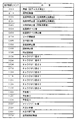
図48は、主基板31から音声制御基板70に送出される音声制御コマンドデータの例を示す説明図である。図48に示された各音声制御コマンドデータは8ビットで構成され、それぞれ、効果音の種類を指定する。上述したように、各特別図柄プロセスデータは、それぞれ5バイトからなる1つ以上のデータグループを含む。各データグループの1,2バイト目に格納されているタイマ値にもとづくプロセスタイマがタイムアップすると、次の5バイトのデータグループが使用される。すなわち、そのデータグループ中のランプ制御コマンドデータがランプ制御基板35に送出され、音声制御コマンドデータが音声制御基板70に送出される。なお、図48に示された例では、コマンド[02(H)],[03(H)]が効果音発生指示に対応し、[04(H)] が特殊効果音発生指示に対応している。
【0190】
図49は、この実施の形態における特別図柄プロセス処理の全図柄変動開始処理(ステップS304)を示すフローチャートである。ステップS302,S303の停止図柄設定処理およびリーチ動作設定処理においてリーチ態様と停止図柄が決定されると、それらを指示するための表示制御コマンドの送出制御が行われるのであるが、ステップS304では、CPU56は、まず、コマンドの送出完了を待つ(ステップS304a)。
【0191】
表示制御コマンドの送出が完了すると、CPU56は、図柄変動態様に対応した特別図柄プロセスデータを選択し(ステップS304d)、特別図柄プロセスデータの1,2バイト目に設定されているプロセスタイマ値を用いてプロセスタイマをスタートする(ステップS304e)。そして、ステップS305に移行するように、特別図柄プロセスフラグを更新する(ステップS304c)。
【0192】
図50は、この実施の形態における特別図柄プロセス処理の全図柄停止待ち処理(ステップS305)を示すフローチャートである。ステップS305では、CPU56は、プロセスタイマがタイムアップしたか否か確認する(ステップS305e)。タイムアップしたら、プロセスデータにおける次に設定されているデータが終了コードであるか否か確認する(ステップS305f)。終了コードでなければ、プロセスデータにおける3,4,5バイト目に設定されているデータに従って、ランプ制御コマンド、音声制御コマンドおよび表示制御コマンドの送出処理を行う(ステップS305g,305h,305i)。
【0193】
特別図柄プロセスデータにおける終了コードを検出した場合には、全図柄停止を指示する表示制御コマンドを設定する(ステップS305b)。そして、表示制御コマンドデータ送出要求をセットし(ステップS305c)、ステップS306に移行するように、特別図柄プロセスフラグを更新する(ステップS305d)。
【0194】
以上のような特別図柄プロセスデータを用いた制御によって、主基板31のCPU56は、適切なタイミング(図45に例示されたタイミング)で効果音および特殊効果音の発生を指示する音声制御コマンドを音声制御基板70に送出することができる。音声制御基板70では、音声制御コマンドは、音声制御用CPU701(図6参照)で受信される。そして、音声制御用CPU701は、受信したコマンドにもとづいてスピーカ27を駆動する。
【0195】
図51は、音声制御用CPU701による音声IC制御処理を示すフローチャートである。音声IC制御処理において、音声制御用CPU701は、通信終了フラグがセットされているか否か確認する(ステップS132)。通信終了フラグとは、音声制御コマンドを受信する処理(図示せず)において音声制御コマンドが受信されたときにセットされるフラグである。通信終了フラグがセットされている場合には、通信終了フラグをリセットするとともに(ステップS133)、音声制御コマンドを受信する処理において受信コマンド格納エリアに格納された音声制御コマンドに応じた音声LSI制御用のデータをROMから読み出す(ステップS134)。
【0196】
音声制御基板70に搭載されているROMには、図48に示された各音声制御コマンドに応じた音を音声合成回路(音声合成用LSI;例えばディジタルシグナルプロセッサ)702に発生させるための制御データが格納されている。音声制御用CPU701は、受信した各音声制御コマンドデータに対応した制御データをROMから読み出す。
【0197】
この実施の形態では、音声合成回路702は、転送リクエスト信号(SIRQ)、シリアルクロック信号(SICK)、シリアルデータ信号(SI)および転送終了信号(SRDY)によって制御される。音声合成回路702は、SIRQがローレベルになると、SICKに同期してSIを1ビットずつ取り込み、SRDYがローレベルになるとそれまでに受信した各SIからなるデータを1つの音声再生用データと解釈する。従って、音声制御用CPU701は、SIRQをオン(ローレベル)にして(ステップS135)、ROMから読み出した制御データをSICKに同期してSIとして出力し(ステップS136)、出力が完了したらSRDYをローレベルにする(ステップS137)。音声合成回路702は、SIによって制御データを受信すると、受信した制御データに応じた音声を発生する。
【0198】
以上のように、この実施の形態では、大当り発生の期待度に応じて図柄停止時に効果音または特殊効果音を発生するので、音によって遊技者の大当り発生に関する期待度を高めて遊技の興趣を増進させることができる。
【0199】
【発明の効果】
以上のように、本発明によれば、遊技機を、表示制御手段が、コマンド出力手段が出力した図柄の表示結果を特定するためのコマンドにもとづいて最終停止図柄を特定する最終停止図柄特定手段と、最終停止図柄特定手段が特定した最終停止図柄が最終停止表示される前に、いずれの仮図柄から再抽選動作を開始させるかを抽選により決定する仮図柄決定手段と、仮図柄決定手段が決定した仮図柄を表示した後、再抽選動作態様の表示制御を行う再抽選制御手段とを含み、再抽選制御手段は、仮図柄が表示されてから最終停止図柄が表示されるまでの図柄変化数に関わらず、仮図柄の表示時から最終停止図柄を表示するまでの時間が同一である再抽選動作態様の表示制御を行うように構成したので、表示制御手段に送出されるコマンド数を増やすことなく図柄変動の種類を増加することができ、その結果、図柄変動の種類を増加しても遊技制御手段の図柄表示に関する制御の負担を軽くすることができる効果がある。
【図面の簡単な説明】
【図1】 パチンコ遊技機を正面からみた正面図である。
【図2】 パチンコ遊技機の内部構造を示す全体背面図である。
【図3】 パチンコ遊技機の遊技盤を背面からみた背面図である。
【図4】 主基板における回路構成の一例を示すブロック図である。
【図5】 表示制御基板の回路構成を示すブロック図である。
【図6】 音声制御基板の回路構成例を示すブロック図である。
【図7】 基本回路のメイン処理を示すフローチャートである。
【図8】 各乱数を示す説明図である。
【図9】 打球が始動入賞口に入賞したことを判定する処理を示すフローチャートである。
【図10】 可変表示の停止図柄を決定する処理およびリーチ種類を決定する処理を示すフローチャートである。
【図11】 大当り判定の処理を示すフローチャートである。
【図12】 特別図柄プロセス処理を示すフローチャートである
【図13】 可変表示部に表示される左右中図柄の例を示す説明図である。
【図14】 図柄の可変表示態様を特定可能な表示制御コマンドおよび全図柄の停止を指示する表示制御コマンドを示す説明図である。
【図15】 左図柄の停止図柄の表示制御コマンドを示す説明図である。
【図16】 中図柄の停止図柄の表示制御コマンドを示す説明図である
【図17】 右図柄の停止図柄の表示制御コマンドを示す説明図である
【図18】 主基板から表示制御基板に送信される表示制御コマンドデータを示す説明図である。
【図19】 表示制御コマンドデータの送出タイミングの一例を示すタイミング図である。
【図20】 リーチとしないはずれ時の図柄の変動の一例を示すタイミング図である。
【図21】 リーチ時の図柄の変動の一例を示すタイミング図である。
【図22】 図柄の再変動を説明するための説明図である。
【図23】 特別図柄プロセス処理における全図柄変動開始処理を示すフローチャートである。
【図24】 特別図柄プロセス処理における全図柄停止待ち処理を示すフローチャートである。
【図25】 表示制御データ設定処理の動作例を示すフローチャートである。
【図26】 表示制御データ出力処理を示すフローチャートである。
【図27】 表示制御用CPUのメイン処理を示すフローチャートである。
【図28】 表示制御用CPUのタイマ割込処理を示すフローチャートである。
【図29】 表示制御用CPUのIRQ2割込処理を示すフローチャートである。
【図30】 表示制御プロセス処理を示すフローチャートである。
【図31】 表示制御プロセス処理の表示制御コマンド受信待ち処理を示すフローチャートである。
【図32】 表示制御プロセス処理の仮停止図柄決定処理を示すフローチャートである。
【図33】 表示制御プロセステーブルの構成例を示す説明図である。
【図34】 表示制御プロセステーブルの一例を示す説明図である。
【図35】 表示制御プロセス処理の全図柄停止待ち処理を示すフローチャートである。
【図36】 表示制御プロセス処理の全図柄変動開始処理を示すフローチャートである。
【図37】 表示制御プロセス処理の全図柄停止待ち処理を示すフローチャートである。
【図38】 再変動ありの場合のリーチ態様の第2の実施の形態を示すタイミング図である。
【図39】 第2の実施の形態における図柄変動例を示す説明図である。
【図40】 再変動ありの場合のリーチ態様の第3の実施の形態を示すタイミング図である。
【図41】 第3の実施の形態における図柄変動例を示す説明図である。
【図42】 ランダムなコマ送りの例を示す説明図である。
【図43】 再変動ありの場合のリーチ態様の第4の実施の形態を示すタイミング図である。
【図44】 第4の実施の形態における図柄変動例を示す説明図である。
【図45】 効果音によって遊技者の期待感を向上させる図柄変動例を示す説明図である。
【図46】 特別図柄プロセスデータのデータ構成を示す説明図である。
【図47】 特別図柄プロセスデータ例の一部を示す説明図である。
【図48】 音声制御コマンドデータの例を示す説明図である。
【図49】 特別図柄プロセス処理の全図柄変動開始処理を示すフローチャートである。
【図50】 特別図柄プロセス処理の全図柄停止待ち処理を示すフローチャートである。
【図51】 音声制御用CPUによる音声IC制御処理を示すフローチャートである。
【符号の説明】
9 可変表示部
31 遊技制御基板(主基板)
53 基本回路
56 CPU
63 出力バッファ回路
70 音声制御基板
80 表示制御基板
101 表示制御用CPU
102 制御データROM
103 VDP
105 入力バッファ回路[0001]
BACKGROUND OF THE INVENTION
The present invention relates to a gaming machine such as a pachinko gaming machine or a coin gaming machine, and particularly includes a variable display device whose display state can be changed, and a display result in the variable display device becomes a predetermined specific display mode. The present invention relates to a gaming machine that can be given a predetermined gaming value.
[0002]
[Prior art]
As a gaming machine, a variable display device having a variable display unit whose display state can be changed is provided, and a big hit game that is advantageous to the player when the display result of the variable display unit becomes a predetermined specific display mode Some are configured to transition to a state. The variable display device has a plurality of variable display units, and is usually configured to display the display results of the plurality of variable display units at different times. For example, a plurality of pieces of identification information such as symbols are variably displayed on the variable display section. That the display result of the variable display unit is a combination of specific display modes determined in advance is usually referred to as “big hit”. Note that the game value is the right that the state of the variable winning ball device provided in the gaming area of the gaming machine is advantageous for a player who is likely to win a ball, or the advantageous state for a player. It is to generate.
[0003]
When a big hit occurs, for example, the big winning opening is opened a predetermined number of times, and the game shifts to a big hit gaming state in which a hit ball is easy to win. And in each open period, if there is a prize for a predetermined number (for example, 10) of the big prize opening, the big prize opening is closed. And the number of times the special winning opening is opened is fixed to a predetermined number (for example, 16 rounds). An opening time (for example, 29.5 seconds) is determined for each opening, and even if the number of winnings does not reach a predetermined number, the big winning opening is closed when the opening time elapses. In addition, when a predetermined condition (for example, winning in a V zone provided in the big prize opening) is not established at the time when the big prize opening is closed, the big hit game even if the predetermined number of times is not reached The state ends.
[0004]
In addition, among the combinations of “out of” display modes other than the “big hit” combination, the display results are already derived and displayed at a stage where some of the display results of the plurality of variable display portions have not yet been derived and displayed. A state in which the display mode of the variable display unit satisfies a display condition that is a combination of specific display modes is referred to as “reach”. A player plays a game while enjoying how to generate a big hit.
[0005]
The game progress in the gaming machine is controlled by game control means such as a microcomputer. The identification information, character image, and background image displayed on the variable display device are controlled by display control means that operates in accordance with display control command data from the game control means. In general, the identification information, character image, and background image displayed on the variable display device are a display control microcomputer and a video display processor that generates image data in accordance with instructions from the microcomputer and transfers the image data to the variable display device side ( VDP), the program capacity of the display control microcomputer is large.
[0006]
Therefore, the identification information displayed on the variable display device cannot be controlled by the microcomputer of the game control means having a limited program capacity, and is mounted on a board different from the board on which the microcomputer of the game control means is mounted. The display control microcomputer (display control means) is used. The variable display device may be realized by an image display device, but may also be realized by a mechanical component such as a drum. Even when such a drum-type variable display device is used, the variable display device is generally controlled by a display control means mounted on a display control board different from the board on which the game control means is mounted. . When a drum-type variable display device is used, the display control means performs drive control and speed control of a motor or the like that drives each reel on which a plurality of symbols are drawn.
[0007]
[Problems to be solved by the invention]
Accordingly, the game control means for controlling the progress of the game needs to transmit a display control command to the display control means. Then, when trying to enrich the game effects by display, the load on the game control means becomes very large. For example, when the types of symbol variation are increased in order to enrich the variations of game effects, the number of types of commands also increases according to the increased variation types. Therefore, the game control means must handle many types of commands, and the burden on the variable display control of the game control means increases.
[0008]
Therefore, the present invention provides a gaming machine in which the number of commands sent to the display control means does not increase even if the number of symbol variations increases, and the burden of control related to symbol display of the game control means can be reduced. With the goal.
[0009]
[Means for Solving the Problems]
The gaming machine according to the present invention includes a variable display unit having a plurality of display areas whose display states can be changed, and starts changing the symbols displayed in the display area in accordance with the establishment of the change start condition, and displays the symbols. A gaming machine that can be controlled to a specific gaming state advantageous to the player on the condition that the result has become a predetermined specific display mode, a game control means for controlling the progress of the game,Based on the command output by the game control meansDisplay control means for controlling the display of the variable display section, the game control means is a specific game state determination means for determining whether or not to enter a specific game state, and a display content determination for determining display contents of the variable display section Based on the determination of the means and the display content determination meansIncludes variable timeOutputs a command for specifying the change mode (change period, etc.) and a command for specifying the display result of the symbolWhen the fluctuation time has elapsed, a command indicating the final stop of the symbols in all display areas is output.Redrawing operation that can display a temporary symbol different from the final stop symbol and then display the final stop symbol when it is determined that the specific game state is set, The display control means includes the final stop symbol specifying means for specifying the final stop symbol based on the command for specifying the display result of the symbol output by the command output means, and the final stop symbol specifying means Before the final stop symbol is displayed for final stop, the temporary symbol determination means for determining from which temporary symbol the re-lottery operation is started and the temporary symbol determined by the temporary symbol determination means are displayed. Re-lottery control means for performing display control of the lottery operation mode, and the re-lottery control means includes the temporary symbol regardless of the number of symbol changes from when the temporary symbol is displayed until when the final stop symbol is displayed. Line display control of redrawing operation mode is the same time from the time display to display the final stop symbolThe display control means performs display control for finally stopping symbols in all display areas in the variable display section based on the command indicating the final stop of the symbols output from the command output means.It is characterized by.
[0019]
DETAILED DESCRIPTION OF THE INVENTION
Hereinafter, an embodiment of the present invention will be described with reference to the drawings.
First, the overall configuration of a pachinko gaming machine that is an example of a gaming machine will be described. 1 is a front view of the
[0020]
As shown in FIG. 1, the
[0021]
Near the center of the
[0022]
An open /
[0023]
The
[0024]
The hit ball fired from the hit ball launching device enters the
The generation of the continuation right is allowed a predetermined number of times (for example, 15 rounds).
[0025]
When the combination of images in the
[0026]
Further, when the stop symbol on the
[0027]
Next, the structure of the back surface of the
On the back surface of the
[0028]
The
[0029]
FIG. 3 is a rear view of the game board of the
[0030]
In order to perform the winning ball payout control, signals from the winning
[0031]
FIG. 4 is a block diagram illustrating an example of a circuit configuration in the
[0032]
Further, according to the data given from the
[0033]
The
[0034]
Further, an initial reset circuit 65 for resetting the
Note that there is also switch information input to the
[0035]
A ball hitting device for hitting and launching a game ball is driven by a drive motor 94 controlled by a circuit on the launch control board 91. Then, the driving force of the drive motor 94 is adjusted according to the operation amount of the
[0036]
FIG. 5 is a block diagram showing a circuit configuration in the
[0037]
The display control CPU 101 operates in accordance with a program stored in the control data ROM 102. When a strobe signal is input from the
[0038]
Then, the display control CPU 101 performs display control of the screen displayed on the
[0039]
5 also shows a
[0040]
The
[0041]
FIG. 6 is a block diagram showing a configuration example of the voice control command signal transmission portion of the
[0042]
As shown in FIG. 6, the voice control command is output from the output ports (output ports C and D) 573 and 574 of the I /
[0043]
Then, for example, a
[0044]
As the
[0045]
In addition, a
[0046]
Next, the operation of the gaming machine will be described.
FIG. 7 is a flowchart showing the operation of the
[0047]
Next, the CPU 56 performs a stack setting process for setting the designated address of the stack pointer (step S2). In this example, 00FFH is set in the stack pointer. Then, a system check process is performed (step S3). In the system check process, the CPU 56 determines whether or not an error is included in the
[0048]
Next, after performing processing for setting command data sent to the
[0049]
Next, a process of outputting the contents of the storage area for various output data to each output port is performed (data output process: step S6). Also, the process of decrementing the lamp timer by 1 is performed, and when the lamp timer times out (= 0), the lamp data pointer is updated and a new value is set in the lamp timer (lamp timer process: step S7).
[0050]
Further, output data setting processing is performed for setting output data such as address data indicated by the lamp data pointer, jackpot information output to the hall management computer, start information, probability variation information, etc. in the storage area (step S8). Further, various abnormality diagnosis processes are performed by the self-diagnosis function provided in the
[0051]
Next, a process of updating each counter indicating each determination random number such as a big hit determination random number used for game control is performed (step S10).
FIG. 8 is an explanatory diagram showing each random number. Each random number is used as follows.
(1) Random 1: Decide whether or not to generate a big hit (for big hit determination)
(2) Random 2-1 to 2-3: For determining the left and right out-of-line symbols
(3) Random 3: Determines the combination of symbols for jackpot (for determining jackpot symbols)
(4) Random 4: Decide whether or not to reach when falling off (for reach determination)
(5) Random 5: Reach type is determined (for reach type determination)
[0052]
In order to enhance the game effect, random numbers other than the random numbers (1) to (5) are also used.
In step S10, the CPU 56 counts up (adds 1) a counter for generating the jackpot determining random number (1) and the jackpot symbol determining random number (3). That is, they are determination random numbers.
[0053]
Next, the CPU 56 performs special symbol process processing (step S11). In the special symbol process control, corresponding processing is selected and executed according to a special symbol process flag for controlling the
[0054]
Further, the CPU 56 inputs the state of each switch via the switch circuit 58 and performs necessary processing according to the switch state (switch processing: step S13). Further, a process of sending audio data in process data, which will be described later, to the
[0055]
The
[0056]
The
After that, the
[0057]
Next, a method for determining a symbol variably displayed on the
[0058]
When the hit ball wins the
[0059]
Further, in the special symbol process of step S11, the CPU 56 confirms the value of the start winning memorized number as shown in FIG. 10 (step S50). If the starting winning memory number is not 0, the value stored in the random number value storage area corresponding to the starting winning memory number = 1 is read (step S51), the value of the starting winning memory number is decreased by 1, and each The value in the random value storage area is shifted (step S52). That is, the value stored in the random number value storage area corresponding to the starting winning memory number = n (n = 2, 3, 4) is stored in the random number value storing area corresponding to the starting winning memory number = n−1. .
[0060]
Then, the CPU 56 determines the winning / losing based on the value read in step S51, that is, the extracted value of the jackpot determination random number (step S53). Here, the jackpot determination random number takes a value in the range of 0-299. As shown in FIG. 11, at the time of low probability, for example, when the value is “3”, it is determined as “big hit”, and when it is any other value, it is determined as “out of”. When the probability is high, for example, when the value is any one of “3”, “7”, “79”, “103”, “107”, “big hit” is determined. It is determined that it is out of place.
[0061]
When it is determined that the game is a big hit, the CPU 56 determines a big hit symbol (determined symbol) based on the value of the random number for determining the big hit symbol (step S62). Further, a reach type determining random number (random 5) is extracted, and a reach type is determined based on the extracted value (step S57).
[0062]
If it is determined that there is a loss, the CPU 56 determines whether or not to reach (step S58). For example, when the value of random 4, which is a random number for reach determination, is any one of “105” to “1530”, it is determined not to reach. If the value of the reach determination random number is any one of “0” to “104”, it is determined to reach. When determining to reach, the CPU 56 determines the reach symbol.
[0063]
In this embodiment, the left and right symbols are determined according to the value of random 2-1 (step S59). Further, the medium symbol is determined according to the value of random 2-2 (step S60). That is, any symbol corresponding to 0 to 15 of random 2-1 and random 2-2 is determined as a stop symbol. Here, when the determined middle symbol matches the left and right symbols, the symbol corresponding to the value obtained by adding 1 to the random number value corresponding to the middle symbol is set as the determined symbol of the middle symbol so as not to match the jackpot symbol To do. Then, a reach type determination random number (random 5) is extracted, and the reach type is determined based on the extracted value (step S57).
[0064]
If it is decided not to reach in step S58, the left and right middle symbols are decided according to the random values 2-1 to 2-3 (step S61). As will be described later, in this embodiment, in a high probability state, a variation pattern with a shortened variation time is also used as a variation pattern at the time of loss. Therefore, in the high probability state, the CPU 56 determines whether to use the normal fluctuation pattern or the shortened fluctuation pattern using, for example, a predetermined random number.
[0065]
As described above, it is determined whether the display mode of the symbol variation based on the start winning is the big hit, the reach mode, or the off mode, and the combination of the respective stop symbols is determined.
[0066]
In the high probability state, the probability of the next big hit increases, the time until the variable display of the
[0067]
For example, when the combination of stop symbols of the
Further, the random number and the range of the random value used in this embodiment are merely examples, and any random number may be used, and the range setting is also arbitrary.
[0068]
FIG. 12 is a flowchart illustrating an example of a special symbol process processing program executed by the CPU 56. The special symbol process shown in FIG. 12 is a specific process of step S11 in the flowchart of FIG. When performing the special symbol process, the CPU 56 performs any one of steps S300 to S309 shown in FIG. 12 according to the internal state. In each process, the following process is executed.
[0069]
Special symbol variation waiting process (step S300): Waiting for the
[0070]
Special symbol determination process (step S301): When variable symbol special display can be started, the number of start winning memories is confirmed. If the start winning memorized number is not 0, it is determined whether to win or not according to the extracted value of the big hit determination random number. That is, the first half of the process shown in FIG. 10 is executed.
[0071]
Stop symbol setting process (step S302): The stop symbol of the middle left and right symbols is determined.
That is, the middle half of the process shown in FIG. 10 is executed.
[0072]
Reach operation setting process (step S303): It is determined whether or not a reach operation is performed according to the value of the reach determination random number, and the type of reach mode is determined according to the value of the reach random number. That is, the second half of the process shown in FIG. 10 is executed.
[0073]
All symbol variation start processing (step S304): Control is performed so that the
[0074]
All symbol stop waiting process (step S305): Waiting for the end of the variable period, and when the variable period elapses, an all symbol stop command indicating that all symbols displayed on the
[0075]
Big hit display process (step S306): If the stop symbol is a combination of big hit symbols, the internal state (process flag) is updated to shift to step S307. If not, the internal state is updated to shift to step S309. The combination of jackpot symbols is a combination of left and right middle symbols. Reaching is achieved when the left and right symbols are aligned.
[0076]
Big winning opening opening process (step S307): Control for opening the big winning opening is started. Specifically, the counter and the flag are initialized, and the
[0077]
Processing for opening a special prize opening (step S308): Control for sending display control command data for the big prize opening round display to the
[0078]
Big hit end process (step S309): A display for notifying the player that the big hit gaming state has ended is performed. When the display is completed, the internal flag and the like are returned to the initial state, and the internal state is updated to shift to step S300.
[0079]
As described above, when a hit ball is won at the
[0080]
Next, the variation of symbols will be described using a specific example.
FIG. 13 is an explanatory diagram showing an example of the left and right middle symbols used in this embodiment.
As shown in FIG. 13, in this embodiment, the symbols displayed as the left and right middle symbols are the same 12 symbols in the left and right. When the
[0081]
14-17 is explanatory drawing which shows the example of a display control command regarding the design fluctuation transmitted to the
[0082]
FIG. 14 is an explanatory diagram showing a display control command for instructing a change mode and stop of all symbols. As shown in FIG. 14, in this example, the display control commands that can specify the variation mode are “out of”, “total symbol variation during probability variation”, “reach 1 (no re-variation)” to “reach 5 (re-variation). None ”and“ Reach 1 (with re-variation) ”to“ Reach 5 (with re-variation) ”. In addition, in the variation mode of reach 1 (with re-variation) to reach 5 (with re-variation), the re-variation period is excluded from the variation mode of reach 1 (without re-variation) to reach 5 (without re-variation), respectively. The same variation pattern is used.
[0083]
The CPU 56 of the
[0084]
FIG. 15 shows a display control command indicating the stop symbol of the left symbol. As shown in FIG. 15, a stop symbol is designated by a display control command composed of 2-byte control data CMD1 and CMD2. In these designations, the value of the control data CMD1 in the first byte is “8B (H)”.
[0085]
FIG. 16 shows a display control command indicating the stop symbol of the middle symbol. As shown in FIG. 16, a stop symbol is designated by a display control command composed of 2-byte control data CMD1 and CMD2. In these designations, the value of the control data CMD1 in the first byte is “8C (H)”.
[0086]
FIG. 17 shows a display control command indicating the stop symbol of the right symbol. As shown in FIG. 17, a stop symbol is designated by a display control command composed of 2-byte control data CMD1 and CMD2. In these designations, the value of the control data CMD1 in the first byte is “8D (H)”.
[0087]
FIG. 18 is an explanatory diagram showing display control commands transmitted from the
[0088]
FIG. 19 is a timing chart showing an example of the transmission timing of the display control command given from the
[0089]
Hereinafter, examples of symbol variation patterns will be described with reference to FIGS.
FIG. 20 is a timing chart showing an example of a change in symbol when the reach is not reached. FIG. 21 is a timing chart showing an example of symbol variation during reach (when a big hit and not a big hit). And FIG. 22 is explanatory drawing for demonstrating the re-variation of a symbol.
[0090]
In this embodiment, at the time of detachment, as shown in FIG. 20 (A), in the “left” symbol display area in the
[0091]
The display control CPU 101 of the
[0092]
Then, when a display control command for instructing the stop of all symbols is received from the
[0093]
The display control CPU 101 performs display control of the symbols three symbols before the stop symbol at a predetermined timing so that the symbol variation stops at the designated stop symbol in the left and right symbol display areas. Since the left and right stop symbols are notified at the start of the change and the change pattern at the time of the deviation is determined in advance, the display control CPU 101 switches the timing from pattern a to pattern b and from pattern b to pattern c. The switching timing can be recognized, and the symbol three symbols before the symbol to be replaced can also be determined. The determined replacement symbol is notified to the VDP 103, and the VDP 103 displays the notified symbol regardless of the symbol displayed at that time.
[0094]
FIG. 20B shows an example of a variation pattern at the time of deviation in the probability variation state. In this variation pattern, as shown in the figure, the left and right middle symbols are stopped simultaneously after the left and right middle symbols are varied according to the pattern a, the pattern b, and the pattern c.
[0095]
FIG. 21A shows a reach mode in which the left and right middle symbols are determined after the reach operation by the middle symbol is performed, that is, a reach mode in the case of no re-variation. As shown in FIG. 21 (A), the left and right symbols stop after fluctuations by the patterns a, b, and c are performed. At this time, the left and right symbols stop at the same symbol. Then, a reach operation is performed in which the middle symbols fluctuate in a predetermined pattern. As described above, in this embodiment, there are five types of reach 1 (no re-variation) to reach 5 (no re-variation) (see FIG. 14). Depending on each aspect, the reach operation period is different.
[0096]
When the display control command for instructing the stop of all symbols is received from the
[0097]
FIG. 21B shows a reach mode in which the left and right middle symbols are temporarily stopped after the reach operation by the middle symbol is performed, and thereafter the left and right middle symbols start to change again, that is, a reach mode in the case of re-change. In this embodiment, there are five types of variation patterns with re-variation: Reach 1 (with re-variation) to Reach 5 (with re-variation) (see FIG. 14).
[0098]
The fluctuation pattern from the start of the reach n (with re-change) to the end of the reach operation is the same as the change pattern of reach n (without re-change) (n = 1 to 5). Therefore, the time from timing A to timing B shown in FIG. 21B differs depending on the reach type. However, the time from the end of the reach operation (when the middle symbol is temporarily stopped: timing B) until the end of re-variation and the determination of all symbols (timing C) is always controlled to be constant. Hereinafter, a period between the timing B and the timing C is referred to as a re-lottery operation period, and a period during which the symbol actually fluctuates in the re-lottery operation period is referred to as a re-variation period.
[0099]
FIG. 22 is an explanatory diagram illustrating an image display example in the variation mode with re-variation illustrated in FIG. As shown in FIG. 22, after the left and right middle symbols change (see (a)), the left and right symbols stop at the same symbol and reach is established (see (b)). Thereafter, the reach operation is performed, the middle symbol is also stopped, and the big hit is determined (see timing B: (c)).
[0100]
In this embodiment, the left and right middle symbols are temporarily stopped (temporarily stopped), but the left and right middle symbols are displayed small on the edge of the screen under the control of the display control CPU 101 (see (d)). . Further, the display control CPU 101 performs a game effect by displaying the character in motion using most of the screen. In particular, as illustrated in FIG. 22, the final stop symbol is a probability variable symbol (in this example, “7, 7, 7”), and the temporary stop symbol (temporary stop symbol) is a non-probable jackpot symbol (in this example) In the case of “4, 4, 4”), it is possible to make the player feel as if the uncertain variation symbol has changed to a certain probability variation symbol due to the effect of the movement of the character.
[0101]
Note that the display control CPU 101 may perform a game effect by controlling the display of the background or by controlling the background and the character.
[0102]
Then, when a predetermined timing arrives, the left and right middle symbols are changed at a high speed and constant speed (see (e)), and stopped at a fixed symbol (see (f)). The fixed symbols in the left and right are the symbols notified from the CPU 56 of the
[0103]
That is, the display control CPU 101 determines a temporary stop symbol using a random number or the like. For example, if the random number generation range is set to 1 to 10 and the extracted random number value indicates the difference between the fixed symbol and the temporary stop symbol, the number of frames of the difference between the temporary stop symbol and the final stop symbol is There are 10 types of variation patterns that become 1 to 10 symbols. In this embodiment, since there are five types of reach 1 (with re-variation) to reach 5 (with re-variation) as variations with re-variation, there are eventually 50 types of variation patterns with re-variation. Will do.
[0104]
However, the display control commands handled by the CPU 56 of the
[0105]
In addition, since the length from the jackpot determination to all symbol determination (re-lottery operation period) is the same for any variation pattern including the re-variation period, the game control means controls the display of the reach mode with re-variation. When instructed to the means, the timing for determining all symbols can be easily identified.
[0106]
If the number of display control commands is not increased and the length of the re-lottery operation period is made variable by the original control of the display control means, the burden of the game control means does not increase, but the game control means It becomes impossible to recognize the timing of symbol determination. Therefore, in reality, the number of display control commands cannot be increased, and the length of the re-lottery operation period cannot be made variable by the unique control of the display control means. However, when the length of the re-drawing operation period is made constant as in this embodiment, as described above, the game control means can recognize the timing of determining all symbols, so the number of display control commands is The type of variation can be increased without increasing.
[0107]
In order to keep the length of the redrawing operation period constant at all times, the display control means needs to perform symbol replacement control in the revariation period, for example. For example, when the re-lottery operation period is fixed at 5 seconds and the high-speed constant speed re-variation period is 1.0 second, the display control CPU 101 replaces the display symbol with the final stop symbol at the end of the re-variation period. .
[0108]
In this embodiment, there is a case where there is a re-variation, such as reach 1 (without re-variation) to reach 5 (without re-variation) and reach 1 (with re-variation) to reach 5 (with re-variation). In this case, separate display control commands are used, but the display control commands of
[0109]
In this embodiment, the length of the re-lottery period is one type, but there may be two or more types. For example, for Reach 1 (with revariation) to Reach 3 (with revariation), the redrawing period is fixed at 5 seconds, and for Reach 4 (with revariation) to Reach 5 (with revariation), the redrawing period is set. It may be configured to be constant in 8 seconds. Even if the gaming machine is configured in such a manner, the game control means can easily identify the timing of determining all symbols when the display control means is instructed to reach with re-variation, and the display control means The length of the re-drawing period can be made constant (5 seconds or 8 seconds) by replacing and displaying the last stop symbol notified from the game control means at the end of the variable period.
[0110]
Hereinafter, the operations of the game control means and the display control means for realizing the symbol variation in which the re-lottery operation period described above is always constant will be described. FIG. 23 is a flowchart showing all symbol variation start processing (step S304) in the special symbol process shown in FIG. When the reach mode and the stop symbol are determined in the stop symbol setting process and the reach operation setting process in steps S302 and S303, display control command transmission control for instructing them is performed. In step S304, the CPU 56 First, it waits for the completion of command transmission (step S304a). The command transmission completion is notified from the display control data output process (step S5) in the main process (see FIG. 7).
[0111]
In this embodiment, when the CPU 56 starts changing the symbol, any of the commands [80 (H), 01 (H)] to [80 (H), 0C (H)] shown in FIG. Is sent to the
[0112]
When the transmission of the display control command is completed, the CPU 56 starts a variation time timer for measuring the variation time notified to the display control board 80 (step S304b). Then, the special symbol process flag is updated so as to proceed to step S305 (step S304c).
[0113]
FIG. 24 is a flowchart showing the all symbol stop waiting process (step S305) in the special symbol process shown in FIG. In step S305, the CPU 56 checks whether or not the variable time timer has expired (step S305a). When the time is up, a display control command for instructing stop of all symbols is set (step S305b). Then, a display control command data transmission request is set (step S305c), and the special symbol process flag is updated so as to proceed to step S306 (step S305d). The display control command data transmission request is referred to in the display control data setting process (step S3) in the main process (see FIG. 7).
[0114]
As described above, in the special symbol process, the CPU 56 sends information that can specify the variation mode at the start of variation and information that indicates the stop symbol to the
[0115]
FIG. 25 is a flowchart showing an operation example of the display control data setting process (step S4 in the main process shown in FIG. 7). In the display control data setting process, the CPU 56 first checks whether the data sending flag is set (step S411). If not set, it is checked whether or not the display control command data transmission request flag is set (step S412). If the transmission request flag is set, the transmission request flag is reset (step S413). Further, the display control command data to be sent is set in the output data storage area (step S414), and a port output request is set (step S416). The display control command data transmission request flag is set in the special symbol process. The data sending flag is set in the display control data output process described later.
[0116]
FIG. 26 is a flowchart showing the display control data output process (step S5) in the main process shown in FIG. In the display control data output process, the CPU 56 determines whether or not a port output request is set (step S421). If the port output request is set, the port output request is reset (step S422), and the contents of the port storage area (the first byte of the display control command) are output to the output port 571 (step S423). Then, the port output counter is incremented by 1 (step S424). Further, the INT signal is set to a low level (on state) (step S425), and the data sending flag is turned on (step S426).
[0117]
If the port output request is not set, it is determined whether or not the value of the port output counter is 0 (step S431). If the value of the port output counter is not 0, it is confirmed whether or not the value of the port output counter is 1 (step S432). When the value of the port output counter is 1, since the INT signal is turned off for the first byte of the display control command, the INT signal is turned off (= 1) (step S433). Also, the value of the port output counter is incremented by 1 (step S434).
[0118]
When the value of the port output counter is 2 (step S435), the output timing of the second byte of the display control command is reached, so the contents of the port storage area (second byte of the display control command) are output. It outputs to 571 (step S436). Then, the port output counter is incremented by 1 (step S437). Further, the INT signal is set to a low level (step S438).
[0119]
When the value of the port output counter is not 2, that is, when it is 3, the INT signal OFF timing related to the second byte of the display control command is reached, so the value of the port output counter is cleared ( In step S441, the INT signal is turned off (high level) (step S442). Further, the data sending flag is turned off (step S443).
[0120]
In this embodiment, the display control data output process shown in FIG. 26 is executed once every 2 ms. Accordingly, by the data output process shown in FIG. 26, as shown in FIG. 19, 1 byte of data is output every 2 ms.
[0121]
Next, the operation of the display control CPU 101 will be described.
FIG. 27 is a flowchart showing main processing of the display control CPU 101. In the main process, the display control CPU 101 first initializes the RAM, the I / O port, the VDP 103, and the like (step S701). Then, display control is performed so that a demonstration screen appears on the variable display unit 9 (step S702). After that, the display random number update process (update process of the counter that generates the display random number) is repeatedly executed (step S703). As a display random number handled by the display control CPU 101, for example, there is a random number for determining a temporary stop symbol before the re-lottery operation period.
[0122]
In this embodiment, actual variation control and the like are performed by timer interrupt processing. A timer interrupt occurs every 2 ms, for example. As shown in FIG. 28, in the timer interrupt process, the display control CPU 101 executes a display control process process (step S711). In the display control process process, a display control process corresponding to the value of the display control process flag is performed.
[0123]
A display control command from the
[0124]
When the data reception flag is set, when the strobe signal is turned off (step S604), the display control CPU 101 inputs data from the input port and is indicated by the pointer in the display control command data storage area. Input data is stored in the address (step S605).
[0125]
Then, the display control CPU 101 increments the pointer value by 1 (step S606). If the value of the pointer becomes 2 (step S607), it means that the reception of the display control command data consisting of 2 bytes has been completed, so the data reception completion flag is set and data is being received. The flag is reset (steps S608 and S609). Through the processing as described above, the display control data CMD1 and CMD2 are received by the
[0126]
FIG. 30 is a flowchart showing the display control process (step S711) in the timer interrupt process shown in FIG. In the display control process process, any one of steps S720 to S870 is performed according to the value of the display control process flag. In each process, the following process is executed.
[0127]
Display control command reception waiting process (step S720): It is confirmed whether or not a display control command capable of specifying the variation mode has been received by the IRQ2 interrupt process.
[0128]
Temporary stop symbol determination process (step S750): When re-variation is performed, the temporary stop symbol before re-lottery is determined.
[0129]
All symbol variation start processing (step S780): Control is performed so that variation of the left and right middle symbols is started.
[0130]
Symbol variation processing (step S810): Controls the switching timing of each variation state (variation speed, background, character) constituting the variation pattern, and monitors the end of the variation time. In addition, stop control of left and right symbols and re-lottery control are performed.
[0131]
All symbol stop waiting setting process (step S840): When a display control command for instructing all symbols to stop is received at the end of the variation time, control for stopping the symbol variation and displaying the final stop symbol (determined symbol) is performed. Do.
[0132]
Big hit display process (step S870): After the end of the fluctuation time, the control of the probability change big hit display or the normal big hit display is performed.
[0133]
FIG. 31 is a flowchart showing the display control command reception waiting process (step S720). In the display control command reception waiting process, the display control CPU 101 first confirms whether or not a display control command capable of specifying the variation mode has been received (step S721). The display control command that can specify the variation mode is any of the commands [80 (H), 01 (H)] to [80 (H), 0C (H)] shown in FIG. When a display control command that can specify the variation mode is received, the value of the display control process flag is changed to a value corresponding to the temporary stop symbol determination process (step S750) (step S722).
[0134]
The display control command that is first transmitted from the
[0135]
FIG. 32 is a flowchart showing the temporary stop symbol determination process (step S750). In the temporary stop symbol determination process, the display control CPU 101 first determines from the display control command that can specify the variation mode whether it is out of reach (step S751). Specifically, it is wrong if the command A0 or A2 is received.
[0136]
If not, it is confirmed whether or not the left and right stop symbols notified from the
[0137]
If not in step S751, that is, if any of the commands [80 (H), 03 (H)] to [80 (H), 0C (H)] is received, the left and right stop symbols are the same. Whether or not (step S756). If they are different, the right stop symbol is made the same as the left stop symbol (step S757). Then, the left and right stop symbols are stored in a predetermined storage area (step S754). Further, the display control CPU 101 uses a value obtained by adding 0.1 seconds to the fluctuation time corresponding to the commands [80 (H), 03 (H)] to [80 (H), 0C (H)] as a monitoring timer. Setting is made (step S759).
[0138]
If the
[0139]
As described above, in this embodiment, the display control CPU 101 uses the commands [80 (H), 01 (H)] to [80 (H), [0C (H)] and the received right / left middle stop symbol are inconsistent, the stop symbol is corrected. Therefore, even if an error occurs in the left / right / middle stop symbol for some reason, the error is corrected. The error is, for example, a case where a bit error occurs in the command due to noise on the cable from the
[0140]
Next, the display control CPU 101 determines to use a process table corresponding to the variation mode (step S763). In each process table, each fluctuation state (fluctuation speed, fluctuation period at that speed, etc.) in the fluctuation mode is set. Each process table is set in the ROM. Then, the display control CPU 101 changes the value of the display control process flag to a value corresponding to the all symbol variation start process (step S780) (step S764).
[0141]
FIG. 33 is an explanatory diagram of a configuration example of the process table. In each process table corresponding to each variation mode, symbol variation data such as a variation rate, a variation period at that rate, a background and a character switching timing, etc. are set in time series. In addition, a process timer value for determining a fluctuation period at a certain speed is also set. Each process table includes a plurality of process data in units of 3 bytes, and 2 bytes among 3 bytes are used as a process timer value and 1 byte is used as symbol variation data. In addition, when not all symbol variation data can be expressed with 1 byte, the size of the process table is, for example, 4 bytes.
[0142]
The display control CPU 101 can know that some display state must be changed due to the time-up of the process timer. The display state to be changed can be known from the setting value of the third byte of the next process data in the process table.
[0143]
As an example, FIG. 34 shows a configuration example of a process table when the variation pattern shown in FIG. 21B is used. The display control CPU 101 first controls the V103DP so that the left and right middle symbols are varied at a low speed when the symbol variation starts. Then, the timer is started with the process timer value set at the beginning ((1)) of the process table. When the timer expires, the control state of the VDP 103 is changed with the control contents set in the symbol variation data (1), and the timer is started with the process timer value (2). When the timer expires, the control state of the VDP 103 is changed according to the control content set in the symbol variation data of (2), and the timer is started with the process timer value of (3).
[0144]
When the timer expires, the control state of the VDP 103 is changed with the control content set in the symbol variation data (3), and the timer is started with the process timer value (4). At this stage, the right and left middle symbols are increased in the fluctuation speed by one step in the fluctuation mode of the pattern a.
[0145]
Thereafter, when the timer expires, the control state is changed based on the symbol variation data, and the timer is started using the next process timer value in the process table. Therefore, after 4.2 seconds have elapsed after all the symbols in the left and right have entered the high-speed fluctuation state by pattern b (corresponding to (9)), in order for the fluctuation state of the left symbol to be due to pattern c, The control state is changed so that the fluctuation speed of the left symbol is medium (corresponding to (10)).
[0146]
When the process timers (11) to (13) time out, reach is determined. Thereafter, the process timer corresponding to each fluctuation pattern during the reach operation is sequentially started (omitted in FIG. 34), and when the process timer of (14) times out, the big hit is fixed and the temporary stop symbols in the left and right are stopped and displayed. The
[0147]
Further, a process timer for setting the temporary stop period of the left and right middle symbols is started (corresponding to (15)), and when the process timer times out, the process timer for setting the re-variation period is started ((16 )). When the process timer times out, the display control CPU 101 performs control to finally stop the left and right middle symbols.
[0148]
The process table further includes the background and the character switching timing, but in FIG. 34, data other than the data relating to the character in the re-lottery operation period is omitted.
[0149]
FIG. 35 is a flowchart showing all symbol variation start processing (step S780). In the all symbol variation start processing, the display control CPU 101 starts a timer with the process timer value set at the beginning of the process table determined to be used (step S781). Also, the symbol variation control and the background and character display control are started based on the data indicating the variation state set in the third byte (step S782). Then, the value of the display control process flag is changed to a value corresponding to the symbol changing process (step S810) (step S783).
[0150]
FIG. 36 is a flowchart showing the symbol variation processing (step S810). In the symbol variation processing, the display control CPU 101 checks whether or not the process timer has timed out (step S811). If the process timer has timed out, the pointer indicating the data in the process table is incremented by 3 (step S812). Then, it is confirmed whether or not the data in the area pointed to by the pointer is an end code (step S813). If it is not an end code, the symbol variation control, the background and character display control are changed based on the data indicating the variation state set in the third byte of the process data pointed to by the pointer (step S814). The timer is started with the process timer value set in the byte (step S815).
[0151]
If it is an end code in step S813, the value of the display control process flag is changed to a value corresponding to the all symbol stop waiting process (step S840) (step S816).
[0152]
FIG. 37 is a flowchart showing the all symbol stop waiting process (step S840). In the all symbol stop waiting process, the display control CPU 101 confirms whether or not a display control command instructing all symbol stops has been received (step S841). If a display control command for instructing stop of all symbols has been received, control is performed to stop the symbols with the stored stop symbol (step S842). Then, in order to monitor the time until reception of the next display control command, a command non-reception timer is started (step S843).
[0153]
If the display control command for designating all symbols to be stopped has not been received, it is confirmed whether or not the monitoring timer has timed out (step S845). If time-out occurs, it is determined that some abnormality has occurred, and control is performed to display an error screen on the variable display unit 9 (step S846).
[0154]
After performing the process of step S843, the display control CPU 101 sets the value of the display control process flag to a value corresponding to the jackpot display process (step S870) (step S844).
[0155]
As described above, in this embodiment, the game control means, that is, the CPU 56 of the
[0156]
Then, the game control means gives a display control command indicating stop of all symbols to the display control means when the variation period ends, and the display control means determines the symbol by the display control command indicating stop of all symbols. Therefore, the symbol is surely determined at the timing managed by the game control means. As in this embodiment, the game control means transmits information that can specify the variation time and information about the stop symbol at the time related to the symbol variation start, and then the display control unit decides the variation pattern independently. When symbol replacement control or the like is performed, a considerable part of the display control is executed by the display control means.
[0157]
Then, since the game control unit cannot recognize a specific variation pattern, there is a possibility that the variation deviates from the variation time determined by the game control unit unless any countermeasure is taken. However, if the game control means is configured to give a display control command indicating stop of all symbols to the display control means when the fluctuation period ends, the symbols are surely determined at the end of the fluctuation time determined by the game control means. . Further, if an error display is performed when a display control command for instructing all symbols to be stopped cannot be received, it is immediately recognized that an abnormality has occurred.
[0158]
Furthermore, in this embodiment, when the re-lottery period is included, the re-lottery period is the same regardless of the number of symbol changes in the final stop symbol with respect to the temporary stop symbol. Accordingly, the game control means can easily identify the timing for determining all symbols when the display control means is instructed to reach with re-variation. Therefore, the game control means does not have to handle the number of display control commands corresponding to the number of changed frames (difference between the temporary stop symbol and the final stop symbol) during the re-variation period. That is, the game control means only needs to handle the number of display control commands corresponding to the type of reach mode, and the control load related to variable display of the game control means increases even if the number of change frames in the re-variation period is large. Never do. As already described, the re-lottery period with a constant period length may be one type or multiple types.
[0159]
In addition, as shown in FIG. 22, a temporary stop period in which the fluctuation of the symbol is temporarily stopped is provided in the re-lottery operation period, and during this period, the display control CPU 101 and the VDP 103 are left and right in the
[0160]
In this embodiment, in the re-lottery operation period, the right and left middle symbols are temporarily stopped before the start of re-variation. However, high-speed fluctuation may also be performed during that period. Even if such control is performed, the design does not hinder the effect of the re-drawing operation due to the change of the character or the background.
[0161]
Further, during the re-variation period, the left and right middle symbols are changed at high speed, and the symbols are finally stopped immediately after the elapse of the period, so that the variable symbol display control during the re-variation period is easy. It is also effective to perform display control that eliminates the re-variation period and immediately replaces the temporary stop symbol with the final stop symbol.
[0162]
FIG. 38 is a timing chart showing another example of the reach mode (second embodiment) when there is a re-variation. Also in this example, the time from the end of the reach operation (when the middle symbol is temporarily stopped: timing B) to when the re-variation ends and all symbols are determined (timing C) is always controlled to be constant. However, in this example, in the re-lottery operation period, the symbol is first changed again, and the symbol is finally stopped after being changed again in the temporary stop period.
[0163]
FIG. 39 is an explanatory diagram showing an example of symbol variation in the second embodiment shown in FIG. The variation mode shown in FIG. 38 can be realized by the
[0164]
As shown in FIG. 39, after the left and right middle symbols change (see (a)), the left and right symbols stop at the same symbol and reach is established (see (b)). Thereafter, a reach operation is performed due to the middle symbol fluctuation, the middle symbol is also stopped, and the big hit is determined (see timing B: (c)). In this embodiment, during the re-lottery operation period, the left and right middle symbols are changed temporarily and then temporarily stopped (see (d) and (e)). The middle symbol is controlled to swing up and down (see (e)). That is, control is performed so as to repeat forward rotation and reverse rotation of the motor that drives the reel of medium symbols.
[0165]
At this time, the display control CPU performs symbol display on the display unit so that the reach by the probability variation symbol and the reach by the non-probability variation symbol are established (see (e)). Further, when entering the probability variation state, a combination of probability variation symbols is displayed to the player (see (f)). Then, after the left and right middle symbols are changed again (see (g)), the right and left middle symbols are finally stopped (see (h)).
[0166]
Also in this example, the re-lottery operation period ((c) to (h) in FIG. 39) is always controlled to be constant. In addition, the temporary stop symbol illustrated in FIG. 39C is determined by the display control CPU based on a predetermined random number or the like. Therefore, the display control CPU needs to adjust the speed of symbol variation in order to temporarily stop the left and right middle symbols at the timing B shown in FIG. 38 with the determined temporary stop symbol. For example, in the high-speed fluctuation period from timing A to reach determination shown in FIG. 38, the fluctuation speed, that is, the rotation speed of the motor that drives the symbol reel is increased or decreased with respect to a predetermined speed.
[0167]
Further, the display control CPU adjusts the fluctuation speed in the symbol re-variation period in accordance with the number of frames of the difference between the temporary stop symbol and the confirmed symbol in order to make the length of the re-lottery operation period constant. For example, when the number of difference frames is large, the fluctuation speed is increased (the rotation speed of the motor is increased), and when the number of difference frames is small, the fluctuation speed is decreased.
[0168]
In the second embodiment, in the re-lottery operation period, the player's expectation is improved by combining the display of the probability variation symbol and the non-probability variation symbol. Therefore, the display control is simpler than the case of improving the player's expectation during the re-lottery operation period by the character or background as in the first embodiment described above.
[0169]
In this embodiment, the case where the drum type variable display unit is used has been described. However, the same display control can be performed using the image display type
[0170]
FIG. 40 is a timing chart showing still another example (third embodiment) of the reach mode in the case of re-variation. Also in this example, the time from the end of the reach operation (when the middle symbol is temporarily stopped: timing B) to when the re-variation ends and all symbols are determined (timing C) is always controlled to be constant. In this example, in the re-lottery operation period, the symbols are finally stopped after the frame feed variation is performed in a state where the left and right middle symbols coincide.
[0171]
FIG. 41 is an explanatory diagram showing an example of symbol variation in the third embodiment shown in FIG. As shown in FIG. 41, after the left and right middle symbols change (see (a)), the left and right symbols stop at the same symbol and reach is established (see (b)). Thereafter, a reach operation is performed due to the middle symbol fluctuation, the middle symbol is also stopped, and the big hit is determined (see timing B: (c)). In this embodiment, the left and right middle symbols are finally stopped (see (e)) after the frame advance variation is performed in the re-lottery operation period (see (d)).
[0172]
In this embodiment, the number of frames to be sent during the re-lottery operation period is always constant. In the example shown in FIG. 40, the number of frames to be sent is always 5. However, the display control CPU 101 does not always variably display the symbols in order, but randomly displays the symbols as shown in FIG. In each example shown in FIG. 42, the final stop symbol is “7, 7, 7” and the temporary stop symbol is “4, 4, 4”, but the display symbols in the middle are different. As in the first embodiment, the temporary stop symbol is determined by the display control CPU 101 based on a random number or the like, for example.
[0173]
In this embodiment, it is easy to keep the length of the redrawing operation period constant.
However, the display control CPU 101 determines the symbol display order based on, for example, a predetermined random number in order to perform random symbol fluctuations. When the feeding time for one frame has elapsed, the VDP 103 is instructed to display a symbol next. As described above, random symbol variation is realized by the display control CPU 101. Therefore, even when such symbol variation is performed, the burden on the game control means does not increase.
[0174]
FIG. 43 is a timing chart showing still another example (fourth embodiment) of the reach mode in the case of re-variation. Also in this example, the time from the end of the reach operation (when the middle symbol is temporarily stopped: timing B) to when the re-variation ends and all symbols are determined (timing C) is always controlled to be constant. However, in this example, in the re-lottery operation period, the symbol is finally stopped after a variation pattern including a temporary stop and a high-speed variation of the symbol is repeated a predetermined number of times (one or more times).
[0175]
FIG. 44 is an explanatory diagram showing an example of symbol variation in the fourth embodiment shown in FIG. The variation mode shown in FIG. 43 can be realized by the
[0176]
In this embodiment, the high-speed re-variation is performed after the temporary suspension period is set in the re-lottery operation period (see (d)). In addition, after the temporary stop period and the high-speed re-variation are repeated a predetermined number of times (see (e)), the left and right middle symbols are finally stopped (see (f)).
[0177]
Also in the fourth embodiment, the re-lottery operation period ((c) to (f) in FIG. 44) is always controlled to be constant. Also, the temporary stop symbol illustrated in FIG. 44C is determined based on a predetermined random number or the like by a display control CPU that controls each symbol reel. Therefore, the display control CPU needs to adjust the speed of the symbol variation in order to temporarily stop the left and right middle symbols at the timing B shown in FIG. 43 with the determined temporary stop symbol. For example, in the high-speed fluctuation period from timing A to reach determination shown in FIG. 43, the fluctuation speed, that is, the rotation speed of the motor that drives the symbol reel is increased or decreased with respect to a predetermined speed.
[0178]
Further, in order to make the length of the re-lottery operation period constant, the fluctuation speed in the symbol re-variation period is adjusted according to the number of frames of the difference between the temporary stop symbol and the confirmed symbol. For example, when the number of difference frames is large, the fluctuation speed in any one or a plurality of re-variation periods is increased (the rotational speed of the motor is increased), and when the number of difference frames is small, any one is selected. What is necessary is just to slow down the fluctuation | variation speed in one or several revariation periods.
[0179]
In the fourth embodiment, in the re-lottery operation period, the player's expectation is improved by combining the temporary stop of the symbol and the high-speed fluctuation. Therefore, the display control is simpler than the case where the player's expectation during the redrawing operation period is improved by the character or background. Even when such symbol variation control is performed, control for determining the temporary stop symbol and keeping the length of the redrawing operation period constant is executed by the display control CPU. Therefore, the burden on the game control means does not increase.
[0180]
In this embodiment, the case where the drum type variable display unit is used has been described. However, the same display control can be performed using the image display type
[0181]
As described above, in the third embodiment, in the gaming machine capable of temporarily stopping and displaying a symbol different from the big win symbol at the time of big hit, and then displaying the final symbol in a final manner, the display control means includes The number of display control commands handled by the game control means is increased because the length of the redrawing operation period by symbol frame advance is made constant, the number of frames to be sent is always kept constant, and the frame advance order is made random. It is possible to perform abundant re-lottery operations without increasing the player's expectation during the re-lottery operation period by simple display control.
[0182]
Further, in the fourth embodiment, in the gaming machine capable of temporarily stopping and displaying a symbol different from the big hit symbol at the time of big hit, and then finalizing and displaying the final symbol, the display control means re-draws While the length of the operation period is kept constant, and the symbol is paused and the high-speed re-variation is performed once or more during the re-drawing operation period, there is still a wealth of re-execution without increasing the number of display control commands handled by the game control means. The lottery operation can be performed, and the player's expectation during the re-lottery operation period can be improved by simple display control.
[0183]
In each of the above-described embodiments, attention is paid to the game effect by the symbol in the re-drawing period, but the player's expectation is improved by the sound effect emitted from the
[0184]
FIG. 45 is an explanatory view showing a symbol display example in such an embodiment. The example shown in FIG. 45A is a symbol display example in the case of being out of place. As shown in FIG. 45A, a sound effect (for example, “Doon”) is generated from the
[0185]
The examples shown in FIGS. 45A and 45B are symbol display examples in the case of reaching.
In the case of reach, a sound effect is generated from the
[0186]
Hereinafter, a method for controlling the sound effects and special sound effects as shown in FIG. 45 will be described. FIG. 46 is an explanatory diagram showing the data configuration of special symbol process data used in the special symbol process processing in this embodiment. The special symbol process data is stored in the ROM 54 of the
[0187]
In this embodiment, it is assumed that the process data is a collection of one or more data groups composed of 5 bytes. A process timer value is set in the first and second bytes of a data group composed of 5 bytes. Lamp control command data is set in the third byte. In the fourth byte, voice control command data is set. In the fifth byte, special symbol display control data (display control command) is set. An end code indicating the end of the process is added to the end of the special symbol process data. When the process timer based on the process timer value set in the 1st and 2nd bytes times out, the process based on the 3rd, 4th and 5th byte data and the start of the process timer based on the next process timer value are performed.
[0188]
FIG. 47 is an explanatory diagram showing a part of the special symbol process data example. For example, in the process data corresponding to the symbol variation accompanied by the generation of the sound effect when the left symbol is stopped and when the right symbol is stopped, 5-byte data referred to when the process timer times out at the timing of the left symbol stop is shown. That is, a process timer value corresponding to the time until the right symbol is stopped is set in the first and second bytes, and a voice control command of a sound effect when the right symbol is stopped is transmitted to the
[0189]
FIG. 48 is an explanatory diagram showing an example of voice control command data sent from the
[0190]
FIG. 49 is a flowchart showing the entire symbol variation start process (step S304) of the special symbol process in this embodiment. When the reach mode and the stop symbol are determined in the stop symbol setting process and the reach operation setting process in steps S302 and S303, display control command transmission control for instructing them is performed. In step S304, the CPU 56 First, it waits for the completion of command transmission (step S304a).
[0191]
When the transmission of the display control command is completed, the CPU 56 selects the special symbol process data corresponding to the symbol variation mode (step S304d), and uses the process timer value set in the first and second bytes of the special symbol process data. The process timer is started (step S304e). Then, the special symbol process flag is updated so as to proceed to step S305 (step S304c).
[0192]
FIG. 50 is a flowchart showing the all symbol stop waiting process (step S305) of the special symbol process in this embodiment. In step S305, the CPU 56 checks whether or not the process timer has expired (step S305e). When the time is up, it is confirmed whether or not the next set data in the process data is an end code (step S305f). If it is not the end code, the lamp control command, the voice control command, and the display control command are sent out according to the data set in the third, fourth, and fifth bytes of the process data (steps S305g, 305h, 305i).
[0193]
When an end code is detected in the special symbol process data, a display control command for instructing all symbols to stop is set (step S305b). Then, a display control command data transmission request is set (step S305c), and the special symbol process flag is updated so as to proceed to step S306 (step S305d).
[0194]
Through the control using the special symbol process data as described above, the CPU 56 of the
[0195]
FIG. 51 is a flowchart showing audio IC control processing by the
[0196]
In the ROM mounted on the
[0197]
In this embodiment, the
[0198]
As described above, in this embodiment, a sound effect or a special sound effect is generated when a symbol is stopped according to the expectation level of occurrence of a big hit. Can be improved.
[0199]
【The invention's effect】
As described above, according to the present invention, the display control means includes a gaming machine,The final stop symbol specifying means for specifying the final stop symbol based on the command for specifying the display result of the symbol output by the command output means, and the final stop symbol specified by the final stop symbol specifying means before the final stop display The temporary design determination means for determining from which temporary symbol the re-drawing operation is started by lottery, and the re-lottery that performs display control of the re-lottery operation mode after displaying the temporary design determined by the temporary design determination means Control means, re-lottery control means,Tentative designAfter is displayedFinal stop patternUntil is displayedNumber of symbol changesRegardless, the time from displaying the temporary symbol to displaying the final stop symbol is the same.Re-drawing operation modeofdisplayDo controlAs a result, the types of symbol variation can be increased without increasing the number of commands sent to the display control means. As a result, even if the number of symbol variations is increased, the control related to symbol display of the game control means There is an effect that can reduce the burden of.
[Brief description of the drawings]
FIG. 1 is a front view of a pachinko gaming machine as viewed from the front.
FIG. 2 is an overall rear view showing the internal structure of the pachinko gaming machine.
FIG. 3 is a rear view of the game board of the pachinko gaming machine as viewed from the back.
FIG. 4 is a block diagram illustrating an example of a circuit configuration on a main board.
FIG. 5 is a block diagram showing a circuit configuration of a display control board.
FIG. 6 is a block diagram illustrating a circuit configuration example of a sound control board.
FIG. 7 is a flowchart showing main processing of the basic circuit.
FIG. 8 is an explanatory diagram showing each random number.
FIG. 9 is a flowchart showing a process of determining that a hit ball has won a start winning opening.
FIG. 10 is a flowchart showing processing for determining a variable display stop symbol and processing for determining a reach type.
FIG. 11 is a flowchart showing a big hit determination process.
FIG. 12 is a flowchart showing a special symbol process.
FIG. 13 is an explanatory diagram showing an example of left and right middle symbols displayed on a variable display unit.
FIG. 14 is an explanatory diagram showing a display control command that can specify a variable display mode of symbols and a display control command that instructs to stop all symbols.
FIG. 15 is an explanatory diagram illustrating a display control command for a stop symbol of a left symbol.
FIG. 16 is an explanatory view showing a stop design display command for middle symbols;
FIG. 17 is an explanatory diagram showing a stop symbol display control command for the right symbol;
FIG. 18 is an explanatory diagram showing display control command data transmitted from the main board to the display control board.
FIG. 19 is a timing chart showing an example of display control command data transmission timing.
FIG. 20 is a timing chart showing an example of symbol variation at the time of non-reach.
FIG. 21 is a timing chart showing an example of symbol variation during reach.
FIG. 22 is an explanatory diagram for explaining symbol re-variation;
FIG. 23 is a flowchart showing all symbol variation start processing in the special symbol process.
FIG. 24 is a flowchart showing an all symbol stop waiting process in the special symbol process.
FIG. 25 is a flowchart illustrating an operation example of display control data setting processing;
FIG. 26 is a flowchart showing display control data output processing.
FIG. 27 is a flowchart showing a main process of the display control CPU.
FIG. 28 is a flowchart showing a timer interrupt process of the display control CPU.
FIG. 29 is a flowchart showing an IRQ2 interrupt process of the display control CPU.
FIG. 30 is a flowchart showing display control process processing;
FIG. 31 is a flowchart showing display control command reception waiting processing of display control process processing;
FIG. 32 is a flowchart showing temporary stop symbol determination processing of display control process processing;
FIG. 33 is an explanatory diagram of a configuration example of a display control process table.
FIG. 34 is an explanatory diagram showing an example of a display control process table.
FIG. 35 is a flowchart showing all symbol stop waiting processing of display control process processing;
FIG. 36 is a flowchart showing all symbol variation start processing of display control process processing;
FIG. 37 is a flowchart showing all symbol stop waiting processing of display control process processing;
FIG. 38 is a timing chart showing the second embodiment of the reach mode in the case of re-variation.
FIG. 39 is an explanatory diagram showing an example of symbol variation in the second embodiment.
FIG. 40 is a timing diagram showing a third embodiment of a reach mode when there is a re-variation.
FIG. 41 is an explanatory diagram showing an example of symbol variation in the third embodiment.
FIG. 42 is an explanatory diagram showing an example of random frame advance.
FIG. 43 is a timing diagram showing a fourth embodiment of a reach mode when there is re-variation.
FIG. 44 is an explanatory diagram showing an example of symbol variation in the fourth embodiment.
FIG. 45 is an explanatory diagram showing an example of symbol variation that improves a player's expectation by using sound effects.
FIG. 46 is an explanatory diagram showing a data configuration of special symbol process data.
FIG. 47 is an explanatory diagram showing a part of a special symbol process data example;
FIG. 48 is an explanatory diagram of an example of voice control command data.
FIG. 49 is a flowchart showing an all symbol variation start process of the special symbol process.
FIG. 50 is a flowchart showing an all symbol stop waiting process of the special symbol process.
FIG. 51 is a flowchart showing audio IC control processing by the audio control CPU.
[Explanation of symbols]
9 Variable display section
31 Game control board (main board)
53 Basic circuit
56 CPU
63 Output buffer circuit
70 Voice control board
80 Display control board
101 CPU for display control
102 Control data ROM
103 VDP
105 Input buffer circuit
Claims (1)
遊技の進行を制御する遊技制御手段と、該遊技制御手段が出力したコマンドにもとづいて前記可変表示部の表示制御を行う表示制御手段とを備え、
前記遊技制御手段は、
前記特定遊技状態とするか否かを決定する特定遊技状態決定手段と、
前記可変表示部の表示内容を決定する表示内容決定手段と、
前記表示内容決定手段の決定にもとづいて図柄の変動時間を含む変動態様を特定するためのコマンドと図柄の表示結果を特定するためのコマンドとを出力し、前記変動時間が経過したときに全ての表示領域における図柄の最終停止を示すコマンドを出力するコマンド出力手段とを含み、
図柄の変動態様には、前記特定遊技状態とすると決定されたときに最終停止図柄とは異なる仮図柄を表示し、その後に前記最終停止図柄を表示することが可能な再抽選動作態様が含まれ、
前記表示制御手段は、
前記コマンド出力手段が出力した前記図柄の表示結果を特定するためのコマンドにもとづいて前記最終停止図柄を特定する最終停止図柄特定手段と、
前記最終停止図柄特定手段が特定した前記最終停止図柄が最終停止表示される前に、いずれの前記仮図柄から再抽選動作を開始させるかを抽選により決定する仮図柄決定手段と、
前記仮図柄決定手段が決定した前記仮図柄を表示した後、再抽選動作態様の表示制御を行う再抽選制御手段とを含み、
前記再抽選制御手段は、前記仮図柄が表示されてから前記最終停止図柄が表示されるまでの図柄変化数に関わらず、前記仮図柄の表示時から前記最終停止図柄を表示するまでの時間が同一である再抽選動作態様の表示制御を行い、
前記表示制御手段は、前記コマンド出力手段から出力された前記図柄の最終停止を示すコマンドにもとづいて、前記可変表示部における全ての表示領域における図柄を最終停止させる表示制御を行う
ことを特徴とする遊技機。A variable display unit having a plurality of display areas whose display states can be changed, and starts to change the symbols displayed in the display area in response to establishment of the change start condition, and the display results of the symbols are determined in advance. A gaming machine that can be controlled to a specific gaming state advantageous to the player on the condition that the specific display mode has been achieved,
Game control means for controlling the progress of the game, and display control means for performing display control of the variable display section based on a command output by the game control means,
The game control means includes
Specific game state determination means for determining whether or not to set the specific game state;
Display content determining means for determining the display content of the variable display section;
Outputting a command for specifying the commands and display results of symbols for identifying a variation mode including varying time of FIG pattern based on the determination of the display content determining means, all when the variation time has elapsed Command output means for outputting a command indicating the final stop of the symbol in the display area of
The symbol variation mode includes a re-lottery operation mode in which a temporary symbol different from the final stop symbol is displayed when it is determined to be the specific gaming state, and then the final stop symbol can be displayed. ,
The display control means includes
Final stop symbol specifying means for specifying the final stop symbol based on a command for specifying the display result of the symbol output by the command output means;
Temporary symbol determining means for determining, by lottery, from which temporary symbol the re-lottery operation is started before the final stop symbol specified by the final stop symbol specifying means is finally displayed.
Re-lottery control means for performing display control of the re-lottery operation mode after displaying the temporary symbol determined by the temporary symbol determiner,
Regardless of the number of symbol changes from when the temporary symbol is displayed until when the final stop symbol is displayed, the re-lottery control means determines the time from when the temporary symbol is displayed until the final stop symbol is displayed. there line display control of the re-lottery operation mode, which is the same,
The display control means performs display control for finally stopping symbols in all display areas in the variable display section based on a command indicating the final stop of the symbols output from the command output means. Gaming machine.
Priority Applications (1)
| Application Number | Priority Date | Filing Date | Title |
|---|---|---|---|
| JP19097499A JP4531158B2 (en) | 1999-07-05 | 1999-07-05 | Game machine |
Applications Claiming Priority (1)
| Application Number | Priority Date | Filing Date | Title |
|---|---|---|---|
| JP19097499A JP4531158B2 (en) | 1999-07-05 | 1999-07-05 | Game machine |
Related Child Applications (1)
| Application Number | Title | Priority Date | Filing Date |
|---|---|---|---|
| JP2009086949A Division JP4723007B2 (en) | 2009-03-31 | 2009-03-31 | Game machine |
Publications (3)
| Publication Number | Publication Date |
|---|---|
| JP2001017674A JP2001017674A (en) | 2001-01-23 |
| JP2001017674A5 JP2001017674A5 (en) | 2009-05-14 |
| JP4531158B2 true JP4531158B2 (en) | 2010-08-25 |
Family
ID=16266779
Family Applications (1)
| Application Number | Title | Priority Date | Filing Date |
|---|---|---|---|
| JP19097499A Expired - Fee Related JP4531158B2 (en) | 1999-07-05 | 1999-07-05 | Game machine |
Country Status (1)
| Country | Link |
|---|---|
| JP (1) | JP4531158B2 (en) |
Families Citing this family (8)
| Publication number | Priority date | Publication date | Assignee | Title |
|---|---|---|---|---|
| JP3974347B2 (en) * | 2001-04-24 | 2007-09-12 | 株式会社ニューギン | Pachinko machine |
| JP4873849B2 (en) * | 2004-10-12 | 2012-02-08 | 株式会社ニューギン | Game machine |
| JP4571100B2 (en) * | 2006-06-14 | 2010-10-27 | 株式会社藤商事 | Bullet ball machine |
| JP2009101181A (en) * | 2008-12-26 | 2009-05-14 | Daiichi Shokai Co Ltd | Game machine |
| JP4656252B2 (en) * | 2009-10-22 | 2011-03-23 | 株式会社三洋物産 | Game machine |
| JP5141745B2 (en) * | 2010-11-08 | 2013-02-13 | 株式会社三洋物産 | Game machine |
| JP5569565B2 (en) * | 2012-08-27 | 2014-08-13 | 株式会社三洋物産 | Game machine |
| JP2014050689A (en) * | 2013-08-23 | 2014-03-20 | Takeya Co Ltd | Game machine |
-
1999
- 1999-07-05 JP JP19097499A patent/JP4531158B2/en not_active Expired - Fee Related
Also Published As
| Publication number | Publication date |
|---|---|
| JP2001017674A (en) | 2001-01-23 |
Similar Documents
| Publication | Publication Date | Title |
|---|---|---|
| JP4137263B2 (en) | Game machine | |
| JP3664911B2 (en) | Game machine | |
| JP4236754B2 (en) | Game machine | |
| JP4443670B2 (en) | Game machine | |
| JP4087007B2 (en) | Game machine | |
| JP3789664B2 (en) | Game machine | |
| JP4401480B2 (en) | Game machine | |
| JP4408985B2 (en) | Game machine | |
| JP3976940B2 (en) | Game machine | |
| JP4087008B2 (en) | Game machine | |
| JP4043635B2 (en) | Game machine | |
| JP4531158B2 (en) | Game machine | |
| JP4680335B2 (en) | Game machine | |
| JP4255569B2 (en) | Game machine | |
| JP4554014B2 (en) | Game machine | |
| JP4087006B2 (en) | Game machine | |
| JP3874974B2 (en) | Game machine | |
| JP4236762B2 (en) | Game machine | |
| JP4913218B2 (en) | Game machine | |
| JP4090624B2 (en) | Game machine | |
| JP4723007B2 (en) | Game machine | |
| JP4741695B2 (en) | Game machine | |
| JP4846860B2 (en) | Game machine | |
| JP4658211B2 (en) | Game machine | |
| JP5090513B2 (en) | Game machine |
Legal Events
| Date | Code | Title | Description |
|---|---|---|---|
| RD03 | Notification of appointment of power of attorney |
Free format text: JAPANESE INTERMEDIATE CODE: A7423 Effective date: 20060118 |
|
| A621 | Written request for application examination |
Free format text: JAPANESE INTERMEDIATE CODE: A621 Effective date: 20060622 |
|
| A521 | Written amendment |
Free format text: JAPANESE INTERMEDIATE CODE: A523 Effective date: 20090330 |
|
| A977 | Report on retrieval |
Free format text: JAPANESE INTERMEDIATE CODE: A971007 Effective date: 20090813 |
|
| A131 | Notification of reasons for refusal |
Free format text: JAPANESE INTERMEDIATE CODE: A131 Effective date: 20090818 |
|
| A521 | Written amendment |
Free format text: JAPANESE INTERMEDIATE CODE: A523 Effective date: 20091016 |
|
| A131 | Notification of reasons for refusal |
Free format text: JAPANESE INTERMEDIATE CODE: A131 Effective date: 20100302 |
|
| A521 | Written amendment |
Free format text: JAPANESE INTERMEDIATE CODE: A523 Effective date: 20100426 |
|
| TRDD | Decision of grant or rejection written | ||
| A01 | Written decision to grant a patent or to grant a registration (utility model) |
Free format text: JAPANESE INTERMEDIATE CODE: A01 Effective date: 20100601 |
|
| A01 | Written decision to grant a patent or to grant a registration (utility model) |
Free format text: JAPANESE INTERMEDIATE CODE: A01 |
|
| A61 | First payment of annual fees (during grant procedure) |
Free format text: JAPANESE INTERMEDIATE CODE: A61 Effective date: 20100609 |
|
| R150 | Certificate of patent or registration of utility model |
Ref document number: 4531158 Country of ref document: JP Free format text: JAPANESE INTERMEDIATE CODE: R150 Free format text: JAPANESE INTERMEDIATE CODE: R150 |
|
| FPAY | Renewal fee payment (event date is renewal date of database) |
Free format text: PAYMENT UNTIL: 20130618 Year of fee payment: 3 |
|
| FPAY | Renewal fee payment (event date is renewal date of database) |
Free format text: PAYMENT UNTIL: 20130618 Year of fee payment: 3 |
|
| FPAY | Renewal fee payment (event date is renewal date of database) |
Free format text: PAYMENT UNTIL: 20130618 Year of fee payment: 3 |
|
| R250 | Receipt of annual fees |
Free format text: JAPANESE INTERMEDIATE CODE: R250 |
|
| R250 | Receipt of annual fees |
Free format text: JAPANESE INTERMEDIATE CODE: R250 |
|
| R250 | Receipt of annual fees |
Free format text: JAPANESE INTERMEDIATE CODE: R250 |
|
| R250 | Receipt of annual fees |
Free format text: JAPANESE INTERMEDIATE CODE: R250 |
|
| R250 | Receipt of annual fees |
Free format text: JAPANESE INTERMEDIATE CODE: R250 |
|
| R250 | Receipt of annual fees |
Free format text: JAPANESE INTERMEDIATE CODE: R250 |
|
| LAPS | Cancellation because of no payment of annual fees |