JP4443670B2 - Game machine - Google Patents
Game machine Download PDFInfo
- Publication number
- JP4443670B2 JP4443670B2 JP13788799A JP13788799A JP4443670B2 JP 4443670 B2 JP4443670 B2 JP 4443670B2 JP 13788799 A JP13788799 A JP 13788799A JP 13788799 A JP13788799 A JP 13788799A JP 4443670 B2 JP4443670 B2 JP 4443670B2
- Authority
- JP
- Japan
- Prior art keywords
- display
- display control
- identification information
- command
- symbol
- Prior art date
- Legal status (The legal status is an assumption and is not a legal conclusion. Google has not performed a legal analysis and makes no representation as to the accuracy of the status listed.)
- Expired - Fee Related
Links
Images


Description
【0001】
【発明の属する技術分野】
本発明は、パチンコ遊技機やコイン遊技機等の遊技機に関し、特に、表示状態が変化可能な可変表示装置を含み、可変表示装置における表示結果があらかじめ定められた特定の表示態様となった場合に所定の遊技価値が付与可能となる遊技機に関する。
【0002】
【従来の技術】
遊技機として、表示状態が変化可能な可変表示部を有する可変表示装置が設けられ、可変表示部の表示結果があらかじめ定められた特定の表示態様となった場合に遊技者に有利となる大当り遊技状態に移行するように構成されたものがある。可変表示装置には複数の可変表示部があり、通常、複数の可変表示部の表示結果を時期を異ならせて表示するように構成されている。可変表示部には、例えば、図柄等の複数の識別情報が可変表示される。可変表示部の表示結果があらかじめ定められた特定の表示態様の組合せとなることを、通常、「大当り」という。なお、遊技価値とは、遊技機の遊技領域に設けられた可変入賞球装置の状態が打球が入賞しやすい遊技者にとって有利な状態になることや、遊技者にとって有利な状態となるための権利を発生させたりすることである。
【0003】
大当りが発生すると、例えば、大入賞口が所定回数開放して打球が入賞しやすい大当り遊技状態に移行する。そして、各開放期間において、所定個(例えば10個)の大入賞口への入賞があると大入賞口は閉成する。そして、大入賞口の開放回数は、所定回数(例えば16ラウンド)に固定されている。なお、各開放について開放時間(例えば29.5秒)が決められ、入賞数が所定個に達しなくても開放時間が経過すると大入賞口は閉成する。また、大入賞口が閉成した時点で所定の条件(例えば、大入賞口内に設けられているVゾーンへの入賞)が成立していない場合には、所定回数に達していなくても大当り遊技状態は終了する。
【0004】
また、「大当り」の組合せ以外の「はずれ」の表示態様の組合せのうち、複数の可変表示部の表示結果のうちの一部が未だに導出表示されていない段階において、既に表示結果が導出表示されている可変表示部の表示態様が特定の表示態様の組合せとなる表示条件を満たしている状態を「リーチ」という。遊技者は、大当りをいかにして発生させるかを楽しみつつ遊技を行う。
【0005】
遊技機における遊技進行はマイクロコンピュータ等による遊技制御手段によって制御される。可変表示装置に表示される識別情報、キャラクタ画像および背景画像は、遊技制御手段からの表示制御コマンドデータに従って動作する表示制御手段によって制御される。可変表示装置に表示される識別情報、キャラクタ画像および背景画像は、一般に、表示制御用のマイクロコンピュータとマイクロコンピュータの指示に応じて画像データを生成して可変表示装置側に転送するビデオディスプレイプロセッサ(VDP)とによって制御されるが、表示制御用のマイクロコンピュータのプログラム容量は大きい。
【0006】
従って、プログラム容量に制限のある遊技制御手段のマイクロコンピュータで可変表示装置に表示される識別情報等を制御することはできず、遊技制御手段のマイクロコンピュータとは別の表示制御用のマイクロコンピュータ(表示制御手段)が用いられる。よって、遊技の進行を制御する遊技制御手段は、表示制御手段に対して表示制御のためのコマンドを送信する必要がある。
【0007】
【発明が解決しようとする課題】
一般に、遊技制御手段は遊技制御基板に搭載され、表示制御手段は表示制御手段に搭載されているので、基板間で送受信されるコマンドには、ノイズ等によってエラーが生ずる可能性がある。コマンドにエラーが生ずると表示制御手段は正規のコマンドを受信することができない。そのような場合には、遊技進行を制御する遊技制御手段が指示した可変表示と異なる可変表示制御が行われる可能性がある。特に、遊技制御手段が1回の識別情報等の可変表示について大まかな情報を表示制御手段に送信し、表示制御手段が具体的な可変表示の演出を行うように構成されている場合には、表示制御手段において1つのコマンドが受信できない場合でも、可変表示を開始できなかったりするといった不都合が生ずることも考えられる。
【0008】
そこで、本発明は、ノイズ等によって表示制御手段が遊技制御手段からのコマンドを受信できない場合であっても、遊技者に不審感を与えないようにすることができる遊技機を提供することを目的とする。
【0009】
【課題を解決するための手段】
本発明による遊技機は、表示状態が変化可能な複数の表示領域を有する可変表示部を含み、変動開始の条件の成立に応じて表示領域に表示される識別情報の変動を開始し、識別情報の表示結果があらかじめ定められた特定表示態様となったときに遊技者に有利な特定遊技状態に制御可能な遊技機であって、遊技の進行を制御する遊技制御手段と、可変表示部の表示制御を行う表示制御手段とを備え、遊技制御手段は、遊技者にとって有利な特定遊技状態とするか否かを決定する特定遊技状態決定手段と、特定遊技状態決定手段が特定遊技状態とする旨に決定しているときに、識別情報の変動時間が経過した後に特定遊技状態に制御する特定遊技状態制御手段と、特定遊技状態決定手段により特定遊技状態としないことに決定されているときに、識別情報の変動表示中にリーチを発生させるか否かをリーチ判定用の乱数を用いて決定するとともに、識別情報の変動時間を決定するときに、複数種類の可変表示パターンのうちの一部の可変表示パターンに対してのみ予め用意され、識別情報の変動期間のうちの識別情報が高速で変動表示される高速変動期間が短縮された短縮変動用の可変表示パターンを含む複数種類の可変表示パターンの中から実行する可変表示パターンを決定することにより変動時間を決定する表示内容決定手段と、識別情報の変動開始の条件の成立に応じて、識別情報の変動を開始させるときにのみ、表示内容決定手段の決定にもとづいて可変表示部における識別情報の変動時間を特定するためのコマンドを出力するとともに、特定遊技状態決定手段の決定にもとづいて表示結果を特定するためのコマンドを出力し、識別情報の変動時間が経過したときに全識別情報の停止を示すコマンドを出力するコマンド出力手段とを含み、コマンド出力手段は、コマンドを出力してからコマンドの取込みを指定する取込信号を出力し、取込信号の出力を終了した後も所定期間が経過するまでコマンドの出力を維持し、表示制御手段は、識別情報の変動時間を特定するためのコマンドが出力されたことにもとづいて、可変表示部において識別情報の変動表示を開始させる変動表示開始手段と、識別情報の変動表示を開始した後、識別情報の変動時間を特定するためのコマンドで特定される変動時間が経過する前に、表示結果を特定するためのコマンドで特定される停止識別情報を揺れながら表示させる揺れ変動表示を行う揺れ変動表示制御手段と、全識別情報の停止を示すコマンドが出力されたことにもとづいて、揺れ変動表示させていた停止識別情報を停止表示させる停止制御手段と、コマンド出力手段によって送信された複数のコマンドを正しく受信できたか否かを判断するコマンド受信判断手段と、コマンド受信判断手段によって複数のコマンドのうち正しく受信できないコマンドがあると判断された場合にはエラー表示を行うエラー表示手段と、全識別情報の停止を示すコマンドを正しく受信できないときに、揺れ変動表示させていた停止識別情報を停止させるタイミングを決めるための監視タイマとを含み、コマンド受信判断手段により識別情報の変動時間を特定するためのコマンドを正しく受信できたと判断されたときに監視タイマが起動され、全識別情報の停止を示すコマンドを正しく受信できないまま監視タイマが所定時間を計時した場合に、停止制御手段は、揺れ変動表示させていた停止識別情報を停止表示させるように構成されている。
【0012】
表示制御手段は、コマンドが正しく受信できなかったことを検知した時点でエラー表示を行うように構成されていてもよい。
【0013】
表示制御手段は、遊技制御手段が認識するエラーとは区別可能にエラー表示を行うように構成されていることが好ましい。
【0014】
表示制御手段は、識別情報の次回の変動が開始されるまでエラー表示を継続するように構成されていてもよい。
【0015】
表示制御手段は、可変表示部の表示内容にエラー表示を重ねて表示するように構成されていてもよい。
【0016】
表示制御手段は、正しく受信できないコマンドがある場合に、そのコマンドに対応したあらかじめ定められた異常時表示制御を行うように構成されていてもよい。
【0017】
表示制御手段は、正しく受信できないコマンドが表示結果を特定するためのコマンドである場合には、異常時表示制御として、あらかじめ定められた識別情報を表示する制御を行うように構成されていてもよい。
【0018】
ここで、あらかじめ定められた識別情報は、例えば、電源投入時に表示される識別情報である。
【0019】
また、あらかじめ定められた識別情報は、例えば、エラー時専用の識別情報である。
【0020】
そして、エラー時専用の識別情報は、通常の変動で用いられる識別情報とは異なるものであってもよい。
【0021】
【発明の実施の形態】
以下、本発明の一実施形態を図面を参照して説明する。
まず、遊技機の一例であるパチンコ遊技機の全体の構成について説明する。図1はパチンコ遊技機1を正面からみた正面図、図2はパチンコ遊技機1の内部構造を示す全体背面図、図3はパチンコ遊技機1の遊技盤を背面からみた背面図である。なお、ここでは、遊技機の一例としてパチンコ遊技機を示すが、本発明はパチンコ遊技機に限られず、例えばコイン遊技機等であってもよい。
【0022】
図1に示すように、パチンコ遊技機1は、額縁状に形成されたガラス扉枠2を有する。ガラス扉枠2の下部表面には打球供給皿3がある。打球供給皿3の下部には、打球供給皿3からあふれた景品玉を貯留する余剰玉受皿4と打球を発射する打球操作ハンドル(操作ノブ)5が設けられている。ガラス扉枠2の後方には、遊技盤6が着脱可能に取り付けられている。また、遊技盤6の前面には遊技領域7が設けられている。
【0023】
遊技領域7の中央付近には、複数種類の図柄を可変表示するための可変表示部9と7セグメントLEDによる可変表示器10とを含む可変表示装置8が設けられている。この実施の形態では、可変表示部9には、「左」、「中」、「右」の3つの図柄表示エリアがある。可変表示装置8の側部には、打球を導く通過ゲート11が設けられている。通過ゲート11を通過した打球は、玉出口13を経て始動入賞口14の方に導かれる。通過ゲート11と玉出口13との間の通路には、通過ゲート11を通過した打球を検出するゲートスイッチ12がある。また、始動入賞口14に入った入賞球は、遊技盤6の背面に導かれ、始動口スイッチ17によって検出される。また、始動入賞口14の下部には開閉動作を行う可変入賞球装置15が設けられている。可変入賞球装置15は、ソレノイド16によって開状態とされる。
【0024】
可変入賞球装置15の下部には、特定遊技状態(大当り状態)においてソレノイド21によって開状態とされる開閉板20が設けられている。この実施の形態では、開閉板20が大入賞口を開閉する手段となる。開閉板20から遊技盤6の背面に導かれた入賞球のうち一方(Vゾーン)に入った入賞球はVカウントスイッチ22で検出される。また、開閉板20からの入賞球はカウントスイッチ23で検出される。可変表示装置8の下部には、始動入賞口14に入った入賞球数を表示する4個の表示部を有する始動入賞記憶表示器18が設けられている。この例では、4個を上限として、始動入賞がある毎に、始動入賞記憶表示器18は点灯している表示部を1つずつ増やす。そして、可変表示部9の可変表示が開始される毎に、点灯している表示部を1つ減らす。
【0025】
遊技盤6には、複数の入賞口19,24が設けられている。遊技領域7の左右周辺には、遊技中に点滅表示される装飾ランプ25が設けられ、下部には、入賞しなかった打球を吸収するアウト口26がある。また、遊技領域7の外側の左右上部には、効果音を発する2つのスピーカ27が設けられている。遊技領域7の外周には、遊技効果LED28aおよび遊技効果ランプ28b,28cが設けられている。そして、この例では、一方のスピーカ27の近傍に、景品玉払出時に点灯する賞球ランプ51が設けられ、他方のスピーカ27の近傍に、補給玉が切れたときに点灯する玉切れランプ52が設けられている。さらに、図1には、パチンコ遊技台1に隣接して設置され、プリペイドカードが挿入されることによって玉貸しを可能にするカードユニット50も示されている。
【0026】
打球発射装置から発射された打球は、打球レールを通って遊技領域7に入り、その後、遊技領域7を下りてくる。打球が通過ゲート11を通ってゲートスイッチ12で検出されると、可変表示器10の表示数字が連続的に変化する状態になる。また、打球が始動入賞口14に入り始動口スイッチ17で検出されると、図柄の変動を開始できる状態であれば、可変表示部9内の図柄が回転を始める。図柄の変動を開始できる状態でなければ、始動入賞記憶を1増やす。なお、始動入賞記憶については、後で詳しく説明する。
【0027】
可変表示部9内の画像の回転は、一定時間が経過したときに停止する。停止時の画像の組み合わせが大当り図柄の組み合わせであると、大当り遊技状態に移行する。すなわち、開閉板20が、一定時間経過するまで、または、所定個数(例えば10個)の打球が入賞するまで開放する。そして、開閉板20の開放中に打球が特定入賞領域に入賞しVカウントスイッチ22で検出されると、継続権が発生し開閉板20の開放が再度行われる。この継続権の発生は、所定回数(例えば15ラウンド)許容される。
【0028】
停止時の可変表示部9内の画像の組み合わせが確率変動を伴う大当り図柄の組み合わせである場合には、次に大当りとなる確率が高くなる。すなわち、高確率状態という遊技者にとってさらに有利な状態となる。
また、可変表示器10における停止図柄が所定の図柄(当り図柄)である場合に、可変入賞球装置15が所定時間だけ開状態になる。さらに、高確率状態では、可変表示器10における停止図柄が当り図柄になる確率が高められるとともに、可変入賞球装置15の開放時間と開放回数が高められる。
【0029】
次に、パチンコ遊技機1の裏面の構造について図2を参照して説明する。
可変表示装置8の背面では、図2に示すように、機構板36の上部に景品玉タンク38が設けられ、パチンコ遊技機1が遊技機設置島に設置された状態でその上方から景品玉が景品玉タンク38に供給される。景品玉タンク38内の景品玉は、誘導樋39を通って玉払出装置に至る。
【0030】
機構板36には、中継基板30を介して可変表示部9を制御する可変表示制御ユニット29、基板ケース32に覆われ遊技制御用マイクロコンピュータ等が搭載された遊技制御基板(主基板)31、可変表示制御ユニット29と遊技制御基板31との間の信号を中継するための中継基板33、および景品玉の払出制御を行う払出制御用マイクロコンピュータ等が搭載された賞球基板37が設置されている。さらに、機構板36には、モータの回転力を利用して打球を遊技領域7に発射する打球発射装置34と、スピーカ27および遊技効果ランプ・LED28a,28b,28cに信号を送るためのランプ制御基板35が設置されている。
【0031】
また、図3はパチンコ遊技機1の遊技盤を背面からみた背面図である。遊技盤6の裏面には、図3に示すように、各入賞口および入賞球装置に入賞した入賞玉を所定の入賞経路に沿って導く入賞玉集合カバー40が設けられている。入賞玉集合カバー40に導かれる入賞玉のうち、開閉板20を経て入賞したものは、玉払出装置97が相対的に多い景品玉数(例えば15個)を払い出すように制御される。始動入賞口14を経て入賞したものは、玉払出装置(図3において図示せず)が相対的に少ない景品玉数(例えば6個)を払い出すように制御される。そして、その他の入賞口24および入賞球装置を経て入賞したものは、玉払出装置が相対的に中程度の景品玉数(例えば10個)を払い出すように制御される。なお、図3には、中継基板33が例示されている。
【0032】
賞球払出制御を行うために、入賞球検出スイッチ99、始動口スイッチ17およびVカウントスイッチ22からの信号が、主基板31に送られる。主基板31に入賞球検出スイッチ99のオン信号が送られると、主基板31から賞球基板37に賞球個数信号が送られる。入賞があったことは入賞球検出スイッチ99で検出されるが、その場合に、主基板31から、賞球基板37に賞球個数信号が与えられる。例えば、始動口スイッチ17のオンに対応して入賞球検出スイッチ99がオンすると、賞球個数信号に「6」が出力され、カウントスイッチ23またはVカウントスイッチ22のオンに対応して入賞球検出スイッチ99がオンすると、賞球個数信号に「15」が出力される。そして、それらのスイッチがオンしない場合に入賞球検出スイッチ99がオンすると、賞球個数信号に「10」が出力される。
【0033】
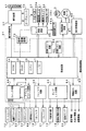
図4は、主基板31における回路構成の一例を示すブロック図である。なお、図4には、賞球制御基板37、ランプ制御基板35、音声制御基板70、発射制御基板91および表示制御基板80も示されている。主基板31には、プログラムに従ってパチンコ遊技機1を制御する基本回路53と、ゲートスイッチ12、始動口スイッチ17、Vカウントスイッチ22、カウントスイッチ23および入賞球検出スイッチ99からの信号を基本回路53に与えるスイッチ回路58と、可変入賞球装置15を開閉するソレノイド16および開閉板20を開閉するソレノイド21を基本回路53からの指令に従って駆動するソレノイド回路59と、始動記憶表示器18の点灯および滅灯を行うとともに7セグメントLEDによる可変表示器10と装飾ランプ25とを駆動するランプ・LED回路60とを含む。
【0034】
また、基本回路53から与えられるデータに従って、大当りの発生を示す大当り情報、可変表示部9の画像表示開始に利用された始動入賞球の個数を示す有効始動情報、確率変動が生じたことを示す確変情報等をホール管理コンピュータ等のホストコンピュータに対して出力する情報出力回路64を含む。
【0035】
基本回路53は、ゲーム制御用のプログラム等を記憶するROM54、ワークメモリとして使用されるRAM55、制御用のプログラムに従って制御動作を行うCPU56およびI/Oポート部57を含む。なお、ROM54,RAM55はCPU56に内蔵されている場合もある。
【0036】
さらに、主基板31には、電源投入時に基本回路53をリセットするための初期リセット回路65と、定期的(例えば、2ms毎)に基本回路53にリセットパルスを与えてゲーム制御用のプログラムを先頭から再度実行させるための定期リセット回路66と、基本回路53から与えられるアドレス信号をデコードしてI/Oポート部57のうちのいずれかのI/Oポートを選択するための信号を出力するアドレスデコード回路67とが設けられている。
なお、玉払出装置97から主基板31に入力されるスイッチ情報もあるが、図4ではそれらは省略されている。
【0037】
遊技球を打撃して発射する打球発射装置は発射制御基板91上の回路によって制御される駆動モータ94で駆動される。そして、駆動モータ94の駆動力は、操作ノブ5の操作量に従って調整される。すなわち、発射制御基板91上の回路によって、操作ノブ5の操作量に応じた速度で打球が発射されるように制御される。
【0038】
図5は、表示制御基板80内の回路構成を、可変表示部9の一実現例であるCRT82および主基板31の出力バッファ回路(出力ドライバ)63とともに示すブロック図である。表示制御用CPU101は、制御データROM102に格納されたプログラムに従って動作し、主基板31から入力バッファ回路105における入力バッファ105aを介してストローブ信号が入力されると、入力バッファ105aを介して表示制御コマンドを受信する。なお、主基板31の出力バッファ回路63は、基本回路53の出力ポートから信号を入力して主基板31から出力する回路であるが、片方向(主基板31から表示制御基板80に向かう方向)にしか信号を伝えない。
【0039】
そして、表示制御用CPU101は、受信した表示制御コマンドに従って、CRT82に表示される画面の表示制御を行う。具体的には、表示制御コマンドに応じた指令をVDP103に与える。VDP103は、キャラクタROM86から必要なデータを読み出す。VDP103は、入力したデータに従ってCRT82に表示するための画像データを生成し、その画像データをVRAM87に格納する。そして、VRAM87内の画像データは、R,G,B信号に変換され、D−A変換回路104でアナログ信号に変換されてCRT82に出力される。
【0040】
なお、図5には、VDP103をリセットするためのリセット回路83、VDP103に動作クロックを与えるための発振回路85、および使用頻度の高い画像データを格納するキャラクタROM86も示されている。キャラクタROM86に格納される使用頻度の高い画像データとは、例えば、CRT82に表示される人物、動物、または、文字、図形もしくは記号等からなる画像などである。
【0041】
入力バッファ回路105における入力バッファ105aは、主基板31から表示制御基板80へ向かう方向にのみ信号を通過させることができる。従って、表示制御基板80側から主基板31側に信号が伝わる余地はない。表示制御基板80内の回路に不正改造が加えられても、不正改造によって出力される信号が主基板31側に伝わることはない。さらに、片方向にしか信号を伝えない出力バッファ回路63を設けることによって、主基板31から表示制御基板80への一方向性の信号伝達をより確実にすることができる。
【0042】
次に遊技機の動作について説明する。
図6は、主基板31における基本回路53の動作を示すフローチャートである。上述したように、この処理は、定期リセット回路66が発するリセットパルスによって、例えば2ms毎に起動される。基本回路53が起動されると、基本回路53は、まず、クロックモニタ制御を動作可能状態にするために、CPU56に内蔵されているクロックモニタレジスタをクロックモニタイネーブル状態に設定する(ステップS1)。なお、クロックモニタ制御とは、入力されるクロック信号の低下または停止を検出すると、CPU56の内部で自動的にリセットを発生する制御である。
【0043】
次いで、CPU56は、スタックポインタの指定アドレスをセットするためのスタックセット処理を行う(ステップS2)。この例では、スタックポインタに00FFHが設定される。そして、システムチェック処理を行う(ステップS3)。システムチェック処理では、CPU56は、RAM55にエラーが含まれているか判定し、エラーが含まれている場合には、RAM55を初期化するなどの処理を行う。
【0044】
次に、表示制御基板80に送出されるコマンドデータをRAM55の所定の領域に設定する処理を行った後に(表示制御データ設定処理:ステップS4)、コマンドデータを表示制御コマンドデータとして出力する処理を行う(表示制御データ出力処理:ステップS5)。
【0045】
次いで、各種出力データの格納領域の内容を各出力ポートに出力する処理を行う(データ出力処理:ステップS6)。また、ランプタイマを1減ずる処理を行い、ランプタイマがタイムアウトしたら(=0になったら)、ランプデータポインタを更新するとともに新たな値をランプタイマに設定する(ランプタイマ処理:ステップS7)。
【0046】
また、ランプデータポインタが示すアドレスのデータ、ホール管理用コンピュータに出力される大当り情報、始動情報、確率変動情報などの出力データを格納領域に設定する出力データ設定処理を行う(ステップS8)。さらに、パチンコ遊技機1の内部に備えられている自己診断機能によって種々の異常診断処理が行われ、その結果に応じて必要ならば警報が発せられる(エラー処理:ステップS9)。
【0047】
次に、遊技制御に用いられる大当り判定用乱数等の各判定用乱数を示す各カウンタを更新する処理を行う(ステップS10)。
図7は、各乱数を示す説明図である。各乱数は、以下のように使用される。
(1)ランダム1:大当りを発生させるか否か決定する(大当り判定用=特別図柄決定用)
(2)ランダム2−1〜2−3:左右中のはずれ図柄決定用
(3)ランダム3:大当り時の図柄の組合せを決定する(大当り図柄決定用=特別図柄判定用)
(4)ランダム4:はずれ時にリーチするか否か決定する(リーチ判定用)
(5)ランダム5:リーチ時の変動時間を決定する(リーチ種類決定用)
【0048】
なお、遊技効果を高めるために、上記(1)〜(5)の乱数以外の乱数も用いられている。
ステップS10では、CPU56は、(1)の大当たり判定用乱数および(3)の大当り図柄判定用乱数を生成するためのカウンタのカウントアップ(1加算)を行う。すなわち、それらが判定用乱数である。
【0049】
次に、CPU56は、特別図柄プロセス処理を行う(ステップS11)。特別図柄プロセス制御では、遊技状態に応じてパチンコ遊技機1を所定の順序で制御するための特別図柄プロセスフラグに従って該当する処理が選び出されて実行される。そして、特別図柄プロセスフラグの値は、遊技状態に応じて各処理中に更新される。また、普通図柄プロセス処理を行う(ステップS12)。普通図柄プロセス処理では、7セグメントLEDによる可変表示器10を所定の順序で制御するための普通図柄プロセスフラグに従って該当する処理が選び出されて実行される。そして、普通図柄プロセスフラグの値は、遊技状態に応じて各処理中に更新される。
【0050】
さらに、CPU56は、スイッチ回路58を介して、各スイッチの状態を入力し、スイッチ状態に応じて必要な処理を行う(スイッチ処理:ステップS13)。また、後述するプロセスデータ中の音声データを音声制御基板70に送出する処理を行う(音声処理:ステップS14)。
【0051】
基本回路53は、さらに、表示用乱数を更新する処理を行う(ステップS15)。すなわち、ランダム2,4,5を生成するためのカウンタのカウントアップ(1加算)を行う。
【0052】
また、基本回路53は、賞球制御基板37との間の信号処理を行う(ステップS16)。すなわち、所定の条件が成立すると賞球制御基板37に賞球個数を示す賞球制御コマンドを出力する。賞球制御基板37に搭載されている賞球制御用CPUは、受信した賞球個数に応じて玉払出装置97を駆動する。
その後、基本回路53は、次に定期リセット回路66からリセットパルスが与えられるまで、ステップS17の表示用乱数更新処理を繰り返す。
【0053】
次に、始動入賞口14への入賞にもとづいて可変表示部9に可変表示される図柄の決定方法について図8〜図10のフローチャートを参照して説明する。図8は打球が始動入賞口14に入賞したことを判定する処理を示し、図9は可変表示部9の可変表示の停止図柄を決定する処理を示す。図10は、大当りとするか否か決定する処理を示すフローチャートである。
【0054】
打球が遊技盤6に設けられている始動入賞口14に入賞すると、始動口センサ17がオンする。メイン処理のステップS8の特別図柄プロセス処理において、図8に示すように、CPU56は、スイッチ回路58を介して始動口センサ17がオンしたことを判定すると(ステップS41)、始動入賞記憶数が最大値である4に達しているかどうか確認する(ステップS42)。始動入賞記憶数が4に達していなければ、始動入賞記憶数を1増やし(ステップS43)、大当り図柄判定用乱数の値を抽出する。そして、それを始動入賞記憶数の値に対応した乱数値格納エリアに格納する(ステップS44)。なお、始動入賞記憶数が4に達している場合には、始動入賞記憶数を増やす処理を行わない。すなわち、この実施の形態では、最大4個の始動入賞口17に入賞した打球数が記憶可能である。
【0055】
図9に示すように、CPU56は、ステップS8の特別図柄プロセス処理において始動入賞記憶数の値を確認する(ステップS50)。始動入賞記憶数が0でなければ、始動入賞記憶数=1に対応する乱数値格納エリアに格納されている値を読み出すとともに(ステップS51)、始動入賞記憶数の値を1減らし、かつ、各乱数値格納エリアの値をシフトする(ステップS52)。すなわち、始動入賞記憶数=n(n=2,3,4)に対応する乱数値格納エリアに格納されている値を、始動入賞記憶数=n−1に対応する乱数値格納エリアに格納する。
【0056】
そして、CPU56は、ステップS51で読み出した値、すなわち抽出されている大当り判定用乱数の値にもとづいて当たり/はずれを決定する(ステップS53)。ここでは、大当り図柄判定用乱数は0〜299の範囲の値をとることにする。図10に示すように、低確率時には例えばその値が「3」である場合に「大当り」と決定し、それ以外の値である場合には「はずれ」と決定する。高確率時には例えばその値が「3」,「7」,「79」,「103」,「107」のいずれかである場合に「大当り」と決定し、それ以外の値である場合には「はずれ」と決定する。
【0057】
大当たりと判定されたときには、大当り図柄決定用乱数(ランダム3)を抽出しその値に従って大当り図柄を決定する(ステップS54)。また、リーチ種類決定用乱数(ランダム5)を抽出しその値にもとづいてリーチ種類を決定する(ステップS57)。
【0058】
はずれと判定された場合には、CPU56は、リーチとするか否か判定する(ステップS58)。例えば、リーチ判定用の乱数であるランダム4の値が「105」〜「1530」のいずれかである場合には、リーチとしないと決定する。そして、リーチ判定用乱数の値が「0」〜「104」のいずれかである場合にはリーチとすることを決定する。リーチとすることを決定したときには、CPU56は、リーチ図柄の決定を行う。
【0059】
この実施の形態では、ランダム2−1の値に従って左右図柄を決定する(ステップS59)。また、ランダム2−2の値に従って中図柄を決定する(ステップS60)。すなわち、ランダム2−1およびランダム2−2の値の0〜15の値に対応したいずれかの図柄が停止図柄として決定される。ここで、決定された中図柄が左右図柄と一致した場合には、中図柄に対応した乱数の値に1加算した値に対応する図柄を中図柄の確定図柄として、大当たり図柄と一致しないようにする。
【0060】
さらに、CPU56は、リーチ種類決定用乱数(ランダム5)を抽出しその値にもとづいてリーチ種類を決定する(ステップS57)。ステップS58において、リーチしないことに決定された場合には、ランダム2−1〜2−3の値に応じて左右中図柄を決定する(ステップS61)。
【0061】
以上のようにして、始動入賞にもとづく図柄変動の表示態様が大当たりとするか、リーチ態様とするか、はずれとするか決定され、それぞれの停止図柄の組合せが決定される。
【0062】
なお、後で詳しく説明するが、この実施の形態では、ステップS57において決定されるリーチ種類は、リーチ時の図柄の可変表示期間を示すものである。
【0063】
また、高確率状態において、次に大当たりとなる確率が上昇するとともに、7セグメントLEDによる可変表示器10の可変表示の確定までの時間が短縮され、かつ、可変表示器10の可変表示結果にもとづく当たり時の可変入賞球装置15の開放回数および開放時間が高められるようにパチンコ遊技機1が構成されていてもよいし、可変表示器10の可変表示結果にもとづく当たりの確率が高くなるように構成されていてもよい。また、それらのうちのいずれか一つまたは複数の状態のみが生ずるパチンコ遊技機1においても本発明は適用可能である。
【0064】
例えば、可変表示部9の停止図柄の組合せが特定図柄となった場合に、大当たりとなる確率は上昇しないが可変表示器10の可変表示結果にもとづく当たり時の可変入賞球装置15の開放回数および開放時間が高められる遊技機においても、リーチとすることが決定されたら、左右の停止図柄を特定図柄の表示態様と一致させるか否か、すなわちどの図柄でリーチ状態を発生させるかが所定の乱数等の手段によって決定される遊技機においても本発明を適用可能である。
また、この実施の形態で用いられた乱数および乱数値の範囲は一例であって、どのような乱数を用いてもよいし、範囲設定も任意である。
【0065】
図11は、CPU56が実行する特別図柄プロセス処理のプログラムの一例を示すフローチャートである。図11に示す特別図柄プロセス処理は、図6のフローチャートにおけるステップS11の具体的な処理である。CPU56は、特別図柄プロセス処理を行う際に、その内部状態に応じて、図11に示すステップS300〜S309のうちのいずれかの処理を行う。各処理において、以下のような処理が実行される。
【0066】
特別図柄変動待ち処理(ステップS300):始動入賞口14(この実施の形態では可変入賞球装置15の入賞口)に打球入賞して始動口センサ17がオンするのを待つ。始動口センサ17がオンすると、始動入賞記憶数が満タンでなければ、始動入賞記憶数を+1するとともに大当り決定用乱数を抽出する。すなわち、図8に示された処理が実行される。
特別図柄判定処理(ステップS301):特別図柄の可変表示が開始できる状態になると、始動入賞記憶数を確認する。始動入賞記憶数が0でなければ、抽出されている大当り決定用乱数の値に応じて大当たりとするかはずれとするか決定する。すなわち、図9に示された処理の前半が実行される。
停止図柄設定処理(ステップS302):左右中図柄の停止図柄を決定する。すなわち、図9に示された処理の中半が実行される。
【0067】
リーチ動作設定処理(ステップS303):リーチ判定用乱数の値に応じてリーチ動作するか否か決定するとともに、リーチ用乱数の値に応じてリーチ時の変動期間を決定する。すなわち、図9に示された処理の後半が実行される。
【0068】
全図柄変動開始処理(ステップS304):可変表示部9において全図柄が変動開始されるように制御する。このとき、表示制御基板80に対して、左右中最終停止図柄と可変表示パターンを指令する情報とが送信される。また、可変表示部9に背景やキャラクタも表示される場合には、それに応じた表示制御コマンドデータが表示制御基板80に送出されるように制御する。
【0069】
全図柄停止待ち処理(ステップS305):所定時間が経過すると、可変表示部9において表示される全図柄が停止されるように制御する。また、適宜、可変表示部9において表示される背景やキャラクタに応じた表示制御コマンドデータが表示制御基板80に送出されるように制御する。
【0070】
大当たり表示処理(ステップS306):停止図柄が大当たり図柄の組み合わせである場合には、内部状態(プロセスフラグ)をステップS307に移行するように更新する。そうでない場合には、内部状態をステップS309に移行するように更新する。なお、大当たり図柄の組み合わせは、左右中図柄が揃った組み合わせである。また、左右図柄が揃うとリーチとなる。
【0071】
大入賞口開放開始処理(ステップS307):大入賞口を開放する制御を開始する。具体的には、カウンタやフラグを初期化するとともに、ソレノイド21を駆動して大入賞口を開放する。
【0072】
大入賞口開放中処理(ステップS308):大入賞口ラウンド表示の表示制御コマンドデータが表示制御基板80に送出する制御や大入賞口の閉成条件の成立を確認する処理等を行う。大入賞口の閉成条件が成立したら、大当り遊技状態の終了条件が成立していなければ内部状態をステップS307に移行するように更新する。大当り遊技状態の終了条件が成立していれば、内部状態をステップS309に移行するように更新する。
【0073】
大当たり終了処理(ステップS309):大当たり遊技状態が終了したことを遊技者に報知するための表示を行う。その表示が終了したら、内部フラグ等を初期状態に戻し、内部状態をステップS300に移行するように更新する。
【0074】
上述したように、始動入賞口14に打球が入賞すると、基本回路53は、ステップS11(図6参照)の特別図柄プロセス処理において、大当たりとするかはずれとするか、停止図柄および可変表示期間を決定するが、その決定に応じた表示制御コマンドを表示制御基板80の表示制御用CPU101に与える。表示制御用CPU101は、主基板31からの表示制御コマンドに応じて可変表示部9の表示制御を行う。
【0075】
図12は、主基板31から表示制御基板80に送信される表示制御コマンドを示す説明図である。図12に示すように、この実施の形態では、表示制御コマンドは、表示制御信号CD0〜CD7の8本の信号線で主基板31から表示制御基板80に送信される。また、主基板31と表示制御基板80との間には、ストローブ信号を送信するための表示制御信号INTの信号線、表示制御基板80の電源となる+5V,+12Vの供給線、および接地レベルを供給するための信号線も配線されている。
【0076】
図13は、主基板31から遊技制御基板80に与えられる表示制御コマンドの送出タイミングの例を示すタイミング図である。この実施の形態では、表示制御コマンドデータを構成する2バイトの表示制御データは、図13に示すように、2ms毎に送出される。そして、各表示制御データに同期してストローブ信号(表示制御信号INT)が出力される。表示制御用CPU101には、ストローブ信号の立ち上がりで割込がかかるので、表示制御用CPU101は、割込処理プログラムによって各表示制御データを取り込むことができる。
【0077】
図14および図15は、図柄の可変表示態様を指示するための表示制御コマンドを示す説明図である。この実施の形態では、2バイトの表示制御データCMD1,CMD2で構成されるコマンド[80H,00H]〜[80H,2AH]の43種類の表示制御コマンドによって、表示制御基板80に対して43種類の可変表示パターンを指定することができる。
【0078】
図14および図15に示された表示制御コマンドにおいて、「通常変動」と「通常変動短縮」とは同じ変動パターンの可変表示パターンである。また、「リーチx」と「リーチx短縮」におけるxが同じ値であれば、「リーチx」と「リーチx短縮」とは同じ変動パターンの可変表示パターンである。ただし、短縮と表示されているパターンとそうでないパターンとは、変動時間のみ異なる。なお、リーチ6,7,8,20,21,22,24の可変表示パターンについては、短縮と表示されているパターンはない。すなわち、それらについては、変動時間が短縮されたパターンは用意されていない。
【0079】
図14および図15に示されているように、短縮パターンを有するリーチ1〜5についての短縮でない可変表示パターンの変動時間は、リーチ7,8の可変表示パターンの変動時間よりも短い。また、リーチ9〜19についての短縮でない可変表示パターンの変動時間は、リーチ19やリーチ20の可変表示パターンの変動時間よりも短い。そして、リーチ23についての短縮でない可変表示パターンの変動時間は、リーチ23,24の可変表示パターンの変動時間よりも短い。このように、短縮パターンを有する可変表示パターンの変動時間は、比較的変動時間の短いものから選定されている。
【0080】
つまり、短縮変動パターンは、比較的変動時間の短い変動パターンの変動時間をさらに短縮したものとなっている。図柄の変動時間が短いということは短期間で変動が終了するということであるから、始動入賞記憶が早く減ることになる。換言すれば、始動入賞記憶が上限に達してしまう可能性が低くなって、遊技者に有利な状況を提供することができる。
【0081】
また、全ての変動パターン(通常変動およびリーチ1〜24)について短縮変動パターンを用意したのでは、表示制御コマンドの総数が多くなってしまう。しかし、この実施の形態のように、全ての変動パターンのうちの一部の変動パターンについてのみ1つの変動パターンに対応した複数の可変表示パターン(この例では、変動時間が短縮された可変表示パターンと変動時間が短縮されていない可変表示パターン)を用意すれば、表示制御コマンド数を削減することができる。なお、全ての変動パターンついて複数の可変表示パターンを用意したのでは、変動パターンの種類の2倍の表示制御コマンドを用意しなければならない(変動時間が短縮された可変表示パターンと変動時間が短縮されていない可変表示パターンとがある場合)。
【0082】
図16には、左図柄に関する停止図柄を指示する表示制御コマンドが示されている。図16に示すように、2バイトの表示制御データCMD1,CMD2で構成される表示制御コマンドによって停止図柄が指定される。なお、それらの指定において、1バイト目の表示制御データCMD1の値は、「8B(H)」である。なお、この実施の形態では、左右中図柄として、それぞれ12種類が存在する。
【0083】
図17には、中図柄に関する停止図柄を指示する表示制御コマンドが示されている。図17に示すように、2バイトの表示制御データCMD1,CMD2で構成される表示制御コマンドによって停止図柄が指定される。なお、それらの指定において、1バイト目の表示制御データCMD1の値は、「8C(H)」である。
【0084】
図18には、右図柄に関する停止図柄を指示する表示制御コマンドが示されている。図18に示すように、2バイトの表示制御データCMD1,CMD2で構成される表示制御コマンドによって停止図柄が指定される。なお、それらの指定において、1バイト目の表示制御データCMD1の値は、「8D(H)」である。
【0085】
その他、可変表示部9に表示される背景や図柄を指定するための表示制御コマンドもあるが、ここでは、その説明を省略する。なお、図15に示されたコマンド[80H,2FH]は、図柄の変動期間の終了時に主基板31から表示制御基板80に送出される「全図柄停止」を指示するコマンドである。
【0086】
図19は、変動開始時から変動終了時までの間に主基板31から表示制御基板80に送出される図柄変動に関する表示制御コマンドの送出タイミングを示すタイミング図である。図19に示すように、この実施の形態では、図柄の変動開始時には、変動開始を指示するための表示制御コマンドが送出される。変動開始を指示するための表示制御コマンドは、図15および図16に示されたコマンド[80H,00H]〜[80H,2AH]のいずれかである。すなわち、1回の変動全体の変動パターンを示すコマンドである。次いで、左右中図柄の停止図柄を示す表示制御コマンドが送出される。そして、変動期間終了時に、「全図柄停止」を指示するコマンド[80H,2FH]が送出される。
【0087】
この実施の形態では、表示制御基板80における表示制御用CPU101が、変動開始を指示するための表示制御コマンドすなわち可変表示パターンを示す表示制御コマンドを受信すると、そのコマンドに応じたあらかじめ決められている変動パターンに従って左右中図柄の可変表示制御を行う。そして、変動期間の終了時に、停止図柄が主基板31からの表示制御コマンドによる左右中図柄の停止図柄となるように、例えば、図柄の差し替え制御等も行う。
【0088】
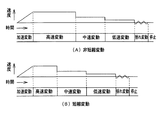
図20は、可変表示パターンの一例を示す説明図である。(A)は、短縮変動パターンではないパターンを示し、(B)は短縮変動パターンを示す。両者は同一の変動パターンであるが、変動時間のみが異なっている。変動時間を異ならせるために、例えば、高速変動期間を短縮する。その他の期間は同一である。なお、図20には、比較的単純な変動パターンが例示されているが、コマ送り変動や逆変動等の変動パターンを含む場合であっても、同一の変動パターンにおける短縮変動パターンではない可変表示パターンと短縮変動パターンとでは、例えば、変動初期の高速変動期間の長さの相違で変動時間の長短が決められる。あるいは、変動期間中の中速変動の期間や低速変動の期間(図20参照)を増減してもよい。
【0089】
図21は、図6に示されたメイン処理における表示制御データ出力処理(ステップS5)を示すフローチャートである。表示制御データ出力処理において、CPU56は、ポート出力要求がセットされているか否か判定する(ステップS421)。ポート出力要求がセットされている場合には、ポート出力要求をリセットし(ステップS422)、ポート格納領域の内容(表示制御コマンドの1バイト目)を出力ポート571に出力する(ステップS423)。そして、ポート出力カウンタを+1する(ステップS424)。さらに、INT信号をローレベル(オン状態)にし(ステップS425)、データ送出中フラグをオンする(ステップS426)。
【0090】
ポート出力要求がセットされていない場合には、ポート出力カウンタの値が0であるか否か判定する(ステップS431)。ポート出力カウンタの値が0でない場合には、ポート出力カウンタの値が1であるか否か確認する(ステップS432)。ポート出力カウンタの値が1である場合には、表示制御コマンドの1バイト目に関するINT信号オフタイミングになっているので、INT信号をオフ(=1)にする(ステップS433)。また、ポート出力カウンタの値を1増やす(ステップS434)。
【0091】
ポート出力カウンタの値が2である場合には(ステップS435)、表示制御コマンドの2バイト目の出力タイミングになっているので、ポート格納領域の内容(表示制御コマンドの2バイト目)を出力ポート571に出力する(ステップS436)。そして、ポート出力カウンタを+1する(ステップS437)。さらに、INT信号をローレベルにする(ステップS438)。
【0092】
そして、ポート出力カウンタの値が2でない場合には、すなわち3である場合には、表示制御コマンドの2バイト目に関するINT信号オフタイミングになっているので、ポート出力カウンタの値をクリアするとともに(ステップS441)、INT信号をオフ(ハイレベル)にする(ステップS442)。また、データ送出中フラグをオフする(ステップS443)。
【0093】
この実施の形態では、図21に示された表示制御データ出力処理は2msに1回実行される。従って、図21に示されたデータ出力処理によって、図13に示されたように、2ms毎に1バイトのデータが出力される。
【0094】
次に、表示制御用CPU101の動作を説明する。
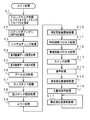
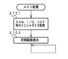
図22は、表示制御用CPU101のメイン処理を示すフローチャートである。メイン処理では、表示制御用CPU101は、まず、RAM、I/OポートおよびVDP103等を初期化する(ステップS701)。そして、可変表示部9に初期画面が出現するように表示制御する(ステップS702)。その後、メイン処理では何の処理も行わない。後述するように、この実施の形態では、実際の表示制御処理は、定期的発生するタイマ割込によって起動される割込処理で実行される。なお、初期画面において、可変表示部9の図柄表示エリアには、例えば、「一」(左図柄),「二」(中図柄),「三」(右図柄)が表示されるとする。
【0095】
この実施の形態では、上述したように、実際の図柄変動制御等はタイマ割込処理によって行われる。タイマ割込は、例えば2ms毎に発生する。図23に示すように、タイマ割込処理では、表示制御用CPU101は、表示制御プロセス処理(ステップS711)を実行する。表示制御プロセス処理では、表示制御プロセスフラグの値に応じた表示制御処理が行われる。
【0096】
主基板31からの表示制御コマンドは、IRQ2割込によって表示制御用CPU101に受信される。図24は、表示制御用CPU101のIRQ2割込処理を示すフローチャートである。IRQ2割込処理において、表示制御用CPU101は、まず、データ受信中フラグがセットされているか否か確認する(ステップS601)。セットされていなければ、この割込が表示制御コマンドデータにおける第1バイトの表示制御データ送出による割込である。そこで、ポインタをクリアするとともに(ステップS602)、データ受信中フラグをセットする(ステップS603)。そして、ステップS604に移行する。ポインタは、表示制御用CPU101が内蔵しているRAMにおける表示制御コマンドデータ格納エリアにおける何バイト目に受信データを格納するか指し示すものである。
【0097】
データ受信中フラグがセットされている場合には、ストローブ信号がオフしたら(ステップS604)、表示制御用CPU101は、入力ポートからデータを入力し、表示制御コマンドデータ格納エリアにおいてポインタによって示されているアドレスに、入力データを格納する(ステップS605)。
【0098】
そして、表示制御用CPU101は、ポインタの値を+1する(ステップS606)。そして、ポインタの値が2になった場合には(ステップS607)、2バイトで構成される表示制御コマンドデータの受信が完了したことになるので、データ受信完了フラグをセットするとともに、データ受信中フラグをリセットする(ステップS608,S609)。以上のような処理によって、2バイトの表示制御データCMD1,CMD2が、表示制御基板80において受信される。
【0099】
図25は、図23に示されたタイマ割込処理における表示制御プロセス処理(ステップS711)を示すフローチャートである。表示制御プロセス処理では、表示制御プロセスフラグの値に応じてステップS720〜S870のうちのいずれかの処理が行われる。各処理において、以下のような処理が実行される。
【0100】
変動開始コマンド受信待ち処理(ステップS720):IRQ2割込処理によって、変動パターンを示す表示制御コマンドを受信したか否か確認する。
【0101】
全図柄変動開始処理(ステップS780):左右中図柄の変動が開始されるように制御する。
【0102】
図柄変動中処理(ステップS810):変動パターンを構成する各変動状態(変動速度や背景、キャラクタ)の切替タイミングを制御するとともに、変動時間の終了を監視する。また、左右図柄の停止制御を行う。
【0103】
全図柄停止設定処理(ステップS840):変動時間の終了時に、図柄の変動を停止し最終停止図柄(確定図柄)を表示する制御を行う。
【0104】
大当り表示処理(ステップS870):変動時間の終了後、確変大当り表示または通常大当り表示の制御を行う。
【0105】
図26は、表示制御コマンドを受信できなかったときの表示制御手段の動作例を説明するための説明図である。図26において、×印は該当コマンドが受信できなかったことを示し、○印は該当コマンドが受信できたことを示す。
【0106】
図26に示すように、変動パターンを指定する表示制御コマンドは受信できなかったが、左右中の停止図柄を示す表示制御コマンドおよび全図柄停止を示す表示制御コマンドを受信できた場合には、図柄の変動を行わないが、全図柄停止を示す表示制御コマンドを受信したときに、左右中の停止図柄を示す表示制御コマンドで指定された図柄を表示する。
【0107】
変動パターンを指定する表示制御コマンドおよび全図柄停止を示す表示制御コマンドを受信できたが、左右中の停止図柄を示す表示制御コマンドの一部または全てを受信できなかった場合には、指定された変動パターンで左右中図柄の変動を行い、全図柄停止を示す表示制御コマンドを受信したときに、左右中の停止図柄を示す表示制御コマンドで指定された図柄を表示する。ただし、表示制御コマンドを受信できなかった停止図柄については、電源投入時に表示される図柄を表示する。
【0108】
変動パターンを指定する表示制御コマンドおよび左右中の停止図柄を示す表示制御コマンドの一部または全ては受信できなかったが、全図柄停止を示す表示制御コマンドを受信できた場合には、図柄の変動を行わないが、全図柄停止を示す表示制御コマンドを受信したときに、左右中の停止図柄を示す表示制御コマンドで指定された図柄を表示する。ただし、表示制御コマンドを受信できなかった停止図柄については、電源投入時に表示される図柄を表示する。
【0109】
変動パターンを指定する表示制御コマンドおよび左右中の停止図柄を示す表示制御コマンドを受信できたが、全図柄停止を示す表示制御コマンドを受信できなかった場合には、指定された変動パターンで左右中図柄の変動を行い、表示制御用CPU101が起動した監視タイマのタイムアウト時に左右中の停止図柄を示す表示制御コマンドで指定された図柄を表示する。
【0110】
変動パターンを指定する表示制御コマンドを受信できたが、全図柄停止を示す表示制御コマンドおよび左右中の停止図柄を示す表示制御コマンドの一部または全てを受信できなかった場合には、指定された変動パターンで左右中図柄の変動を行い、表示制御用CPU101が起動した監視タイマのタイムアウト時に左右中の停止図柄を示す表示制御コマンドで指定された図柄を表示する。ただし、表示制御コマンドを受信できなかった停止図柄については、電源投入時に表示される図柄を表示する。
【0111】
変動パターンを指定する表示制御コマンドおよび全図柄停止を示す表示制御コマンドを受信できなかったが、表示制御コマンドの一部または全てを受信した場合には、表示制御用CPU101が起動した監視タイマのタイムアウト時に左右中の停止図柄を示す表示制御コマンドで指定された図柄を表示する。ただし、表示制御コマンドを受信できなかった停止図柄については、電源投入時に表示される図柄を表示する。
【0112】
なお、以上に説明した全ての場合において、変動パターンを指定する表示制御コマンド、左右中の停止図柄を示す表示制御コマンドおよび全図柄停止を示す表示制御コマンドのうちの1つでも受信できなかった場合には、表示制御用CPU101は、可変表示部9に、エラーが発生した旨を表示する。
【0113】
図27は、図25に示された表示制御プロセス処理の変動開始コマンド受信待ち処理(ステップS720)を示すフローチャートである。変動開始コマンド受信待ち処理において、表示制御用CPU101は、変動パターンを示す表示制御コマンドを受信したか否か確認する(ステップS721)。この実施の形態では、変動パターンを示す表示制御コマンドは、図14および図15に示すように、CMD1が「80(H)」であって、CMD2が「00(H)」〜「2A(H)」の範囲のものである。
【0114】
変動パターンを示す表示制御コマンドを受信した場合には、表示制御プロセスフラグの値を全図柄変動開始処理に対応した値に設定する。(ステップS722)また、エラーフラグがセットされていればエラー表示を消去する(ステップS737)。つまり、変動パターンを示す表示制御コマンド受信にもとづく正常な可変表示が開始されるときに、エラー表示が消去される。なお、エラー表示については後述する。そして、監視タイマをスタートする(ステップS738)。この状況でスタートされる監視タイマは、全図柄停止を示す表示制御コマンドを受信できなかったときに図柄を停止させるタイミングを決めるために用いられる。
【0115】
変動パターンを示す表示制御コマンドを受信していない場合には、表示制御用CPU101は、左図柄停止を示す表示制御コマンドを受信したか否か確認する(ステップS723)。この実施の形態では、左図柄停止を示す表示制御コマンドは、図16に示すように、CMD1が「8B(H)」のコマンドである。左図柄停止を示す表示制御コマンドを受信した場合には、左停止図柄を示す情報を左図柄格納エリアに格納する(ステップS724)。
【0116】
また、表示制御用CPU101は、中図柄停止を示す表示制御コマンドを受信したか否か確認する(ステップS725)。この実施の形態では、中図柄停止を示す表示制御コマンドは、図17に示すように、CMD1が「8C(H)」のコマンドである。中図柄停止を示す表示制御コマンドを受信した場合には、中停止図柄を示す情報を中図柄格納エリアに格納する(ステップS726)。
【0117】
さらに、表示制御用CPU101は、右図柄停止を示す表示制御コマンドを受信したか否か確認する(ステップS727)。この実施の形態では、右図柄停止を示す表示制御コマンドは、図18に示すように、CMD1が「8D(H)」のコマンドである。右図柄停止を示す表示制御コマンドを受信した場合には、右停止図柄を示す情報を右図柄格納エリアに格納する(ステップS728)。
【0118】
ここで、左右中図柄の停止を示す表示制御コマンドを受信したか否か確認するのは、変動パターンを示す表示制御コマンドを受信できなかった場合を考慮してのことである。すなわち、ステップS723、S725またはS727において停止図柄を示す表示制御コマンドを受信したということは、変動パターンを示す表示制御コマンドを受信できずに停止図柄を示す表示制御コマンドを受信したことを意味する。換言すれば、変動パターンを示す表示制御コマンドが正しく受信されなかったことになる。
【0119】
そこで、表示制御用CPU101は、可変表示部9にエラー表示を行う制御を実行するとともに(ステップS730)、監視タイマをスタートする(ステップS731)。なお、エラー表示を行う際に、エラーフラグをセットする。エラーフラグは、上述したステップS737(ただし、次回の変動開始時)で参照される。また、図27に示す処理では、処理を簡便にするために、左、右、中の図柄の停止を示す表示制御コマンドを受信する度に再スタートされる。よって、実質的に、最後に受信した図柄の停止を示す表示制御コマンドの受信時に監視タイマがスタートされることになる。また、ここで設定される監視タイマのタイムアウト時間は、例えば、各変動パターンのうちの最長期間にやや余裕を持たせた時間である。
【0120】
そして、表示制御用CPU101は、全図柄停止を示す表示制御コマンドを受信したか否か確認する(ステップS732)。ここで全図柄停止を示す表示制御コマンドを受信したか否か確認するのは、変動パターンを示す表示制御コマンドを受信できなかったが全図柄停止を示す表示制御コマンドを受信した場合を考慮してのことである。そこで、全図柄停止を示す表示制御コマンドを受信した場合には、変動パターンを示す表示制御コマンドを受信できなかったことを報知するためにエラー表示を行った後(ステップS734)、表示制御プロセスフラグの値を全図柄停止処理に対応した値に設定する(ステップS735)。
【0121】
また、監視タイマが起動されている場合には、監視タイマがタイムアウトしているか否か確認する(ステップS733)。ここで監視タイマがタイムアウトしているか否か確認するのは、変動パターンを示す表示制御コマンドおよび全図柄停止を示す表示制御コマンドをともに受信できなかった場合を考慮してのことである。そこで、監視タイマがタイムアウトしている場合には、エラー表示を行った後に(ステップS734)、表示制御プロセスフラグの値を全図柄停止処理に対応した値に設定する(ステップS735)。
【0122】
図28は、全図柄変動開始処理(ステップS780)を示すフローチャートである。全図柄変動開始処理において、表示制御用CPU101は、変動パターンに応じたプロセステーブルを使用することを決定する(ステップS781)。各プロセステーブルには、その変動パターン中の各変動状態(変動速度やその速度での変動期間等)が設定されている。また、各プロセステーブルはROMに設定されている。
【0123】
図29は、プロセステーブルの構成例を示す説明図である。それぞれの変動パターンに対応した各プロセステーブルには、時系列的に、変動速度やその速度での変動期間、背景やキャラクタの切替タイミング、音声制御データ等が設定されている。また、ある速度での変動期間を決めるためのプロセスタイマ値も設定されている。また、各プロセステーブルは、複数の3バイト単位のプロセスデータで構成されている。
【0124】
表示制御用CPU101は、使用することが決定されたプロセステーブルの最初に設定されているプロセスタイマ値でタイマをスタートさせる(ステップS782)。また、3バイト目に設定されている変動状態を示すデータにもとづいて図柄変動制御、背景およびキャラクタの表示制御を開始する(ステップS783)。そして、表示制御プロセスフラグの値を図柄変動中処理(ステップS810)に対応した値に変更する(ステップS784)。
【0125】
図30は、図柄変動中処理(ステップS810)を示すフローチャートである。図柄変動中処理において、表示制御用CPU101は、プロセスタイマがタイムアウトしたか否か確認する(ステップS811)。プロセスタイマがタイムアウトした場合には、プロセステーブル中のデータを示すポインタを+3する(ステップS812)。そして、ポインタが指す領域のデータが終了コードであるか否か確認する(ステップS813)。終了コードでなければ、ポインタが指すプロセスデータの3バイト目に設定されている変動状態を示すデータにもとづいて図柄変動制御、背景およびキャラクタの表示制御を変更するとともに(ステップS814)、1,2バイト目に設定されているプロセスタイマ値でタイマをスタートさせる(ステップS815)。
【0126】
ステップS813で、終了コードであれば、表示制御プロセスフラグの値を全図柄停止処理(ステップS840)に対応した値に変更する(ステップS816)。
【0127】
また、表示制御用CPU101は、左図柄停止を示す表示制御コマンドを受信したか否か確認する(ステップS820)。左図柄停止を示す表示制御コマンドを受信した場合には、左停止図柄を示す情報を左図柄格納エリアに格納する(ステップS821)。さらに、中図柄停止を示す表示制御コマンドを受信したか否か確認する(ステップS822)。中図柄停止を示す表示制御コマンドを受信した場合には、中停止図柄を示す情報を中図柄格納エリアに格納する(ステップS823)。そして、右図柄停止を示す表示制御コマンドを受信したか否か確認する(ステップS824)。右図柄停止を示す表示制御コマンドを受信した場合には、右停止図柄を示す情報を右図柄格納エリアに格納する(ステップS825)。
【0128】
ここで、左右中図柄の停止図柄を示す表示制御コマンドの受信を確認するのは、変動パターンを示す表示制御コマンドに続いて主基板31から送られてくる左右中図柄の停止図柄を示す表示制御コマンドを受信するためであり、正常時の処理である。
【0129】
ただし、この実施の形態では、停止図柄を示す表示制御コマンドは、左図柄、中図柄、右図柄の順に送られてくる。そこで、送出順が正しくないことを検出した場合には、表示制御用CPU101は、エラー表示を行う。例えば、左図柄の停止図柄を示す表示制御コマンドの次に右図柄の停止図柄を示す表示制御コマンドを受信した場合には、中図柄の停止図柄を示す表示制御コマンドを正しく受信できなかったことになる。その場合には、表示制御用CPU101はエラー表示を行う。
【0130】
図31は、全図柄停止処理(ステップS840)を示すフローチャートである。全図柄停止処理において、表示制御用CPU101は、全図柄停止を指示する表示制御コマンドを受信しているか否か確認する(ステップS841)。全図柄停止を指示する表示制御コマンドを受信していれば、停止図柄表示処理を行う(ステップS842)。そして、停止図柄が大当りを生じさせる図柄の組合せであれば(ステップS843)、表示制御プロセスフラグの値を大当り表示処理(ステップS870)に対応した値に設定する(ステップS844)。そうでなければ、表示制御プロセスフラグの値を変動開始コマンド受信待ち処理(ステップS720)に対応した値に設定する(ステップS845)。
【0131】
全図柄停止を指定する表示制御コマンドを受信していない場合には、監視タイマがタイムアウトしているかどうか確認する(ステップS846)。監視タイマがタイムアウトしている場合も、停止図柄表示処理を行う(ステップS847)。そして、表示制御プロセスフラグの値を変動開始コマンド受信待ち処理(ステップS720)に対応した値に設定する(ステップS845)。
【0132】
図32は、停止図柄表示処理(ステップS842,S847)を示すフローチャートである。停止図柄表示処理において、表示制御用CPU101は、まず、左右中図柄の停止図柄を示す表示制御コマンドを全て受信しているか否か確認する(ステップS851)。具体的には、左右中図柄格納エリアに図柄を示す情報が格納されているか否か確認する。左右中図柄格納エリアの全てに図柄を示す情報が格納されている場合には、その情報を用いて可変表示部9に停止図柄を表示する制御を行う(ステップS852)。
【0133】
次いで、変動開始時に変動パターンを示す表示制御コマンドを受信し、かつ、全図柄停止を指定する表示制御コマンドを受信できていた場合には(ステップS852)、処理を終了する。いずれか一方または双方を受信できていない場合には、可変表示部9にエラー表示を行う(ステップS854)。ただし、エラー表示は、ステップS720の処理段階で既になされている場合もある。
【0134】
ステップS851において、左右中図柄の停止図柄を示す表示制御コマンドのうちいずれか1つでも受信できていないことを確認した場合には、表示制御コマンドを受信できた停止図柄については可変表示部9の該当エリアに表示するとともに、表示制御コマンドを受信できなかった停止図柄については電源投入時に表示される図柄を表示する(ステップS855)。そして、可変表示部9にエラー表示を行う(ステップS854)。ただし、エラー表示は、ステップS720の処理段階で既になされている場合もある。
【0135】
なお、表示制御コマンドを受信できなかった停止図柄について電源投入時に表示される図柄を表示したのでは左右中図柄が揃ってしまう場合には、左右中図柄が揃わないように調整してもよい。また、この実施の形態では表示制御コマンドを受信できなかった停止図柄について電源投入時に表示される図柄を表示するようにしたが、左右中図柄の停止図柄を示す表示制御コマンドのうちいずれか1つでも受信できていない場合には、全ての図柄表示エリアに、電源投入時に表示される各図柄を表示するようにしてもよい。
【0136】
図33は、図柄の表示例を示す説明図である。(A)は電源投入時に表示される左右中図柄の例を示す。(B)は中図柄の停止図柄(この例では「九」)を示す表示制御コマンドを受信できたが、左右図柄の停止図柄を示す表示制御コマンドを受信できなかった場合の表示例を示す。つまり、左右図柄の表示エリアには、電源投入時に表示される「一」および「三」が表示される。
【0137】
(C)はエラー表示の例を示す。エラー表示は、そのときの可変表示部9の表示に対して、エラーを報知するための情報が重ねられたような表示である。このような表示は、例えば、VDP103が制御する複数の表示層(スプライト)の内容を重ねることによって容易に実現することができる。
【0138】
(D)は、主基板31のCPU56が遊技機の異常を検知し、表示制御手段に対してエラー表示を指示したときに、表示制御用CPU101が表示するエラー表示の例を示す。図33(C),(D)に示すように、表示制御手段が検知したエラーにもとづく表示と遊技制御手段が検知した遊技機異常にもとづく表示とは異なっている。よって、遊技者は、図柄の可変表示に関してエラーが生じたことを、容易に遊技機異常と区別して認識することができる。
【0139】
図33に示された例では、停止図柄を示す表示制御コマンドを受信できなかった場合に電源投入時に表示される図柄(この例では、左,中,右の図柄が「一」,「二」,「三」)を表示するようにしたが、あらかじめ定められたエラー報知用の図柄を表示してもよい。図34は、エラー報知用の図柄を表示するための停止図柄表示処理を示すフローチャートである。この停止図柄表示処理では、図32に示された停止図柄表示処理に比べてステップS855の処理が異なっている。すなわち、ここでは、左右中図柄の停止図柄を示す表示制御コマンドのうちいずれか1つでも受信できていないことを確認した場合には、表示制御コマンドを受信できた停止図柄については可変表示部9の該当エリアに表示するとともに、表示制御コマンドを受信できなかった停止図柄についてはエラー報知用の図柄を表示する(ステップS855A)。
【0140】
あらかじめ定められたエラー報知用の図柄として、正常時の図柄の変動において用いられる図柄であって、あらかじめ決められている図柄を用いることができる。例えば、エラー報知用の左,中,右の図柄として「三」,「四」,「五」等を用いてもよい。このように構成しても、表示制御コマンドにエラーが生じた場合には、常に同一のエラー時用図柄が表示されるので、遊技者は、エラーが生じたときに、図柄表示にもとづいてエラーの発生を容易に認識することができる。なお、左右中図柄の停止図柄を示す表示制御コマンドのうちいずれか1つでも受信できていない場合に、全ての図柄表示エリアにエラー報知用の図柄(例えば、左,中および右の図柄として「三」,「四」および「五」)を表示するようにしてもよい。
【0141】
また、エラー時用図柄として、通常の図柄の変動では用いられない図柄を使用してもよい。図35は、通常の図柄の変動では用いられないエラー報知用の図柄の表示例を示す説明図である。この例は、中図柄の停止図柄(この例では「九」)を示す表示制御コマンドを受信できたが、左右図柄の停止図柄を示す表示制御コマンドを受信できなかった場合の表示例である。つまり、左右図柄の表示エリアには、エラー報知用の「E」が表示される。なお、この図柄は、通常時には用いられないエラー専用の図柄である。また、左右中図柄の停止図柄を示す表示制御コマンドのうちいずれか1つでも受信できていない場合には、全ての図柄表示エリアに、エラー報知用の図柄を表示するようにしてもよい。
【0142】
以上のように、この実施の形態では、表示制御手段は、遊技制御手段からの一連の表示制御コマンドのうち正しく受信でなかったものがある場合に、全く図柄の変動を行わないのではなく、正しく受信できたコマンドについてはそのコマンドに応じた表示制御を行う。よって、極力正規の可変表示に近い表示を行うことができ、遊技者に与える不審感を最小限に止めることができる。また、一連の表示制御コマンドのうち1つでも受信できないものがあった場合には、エラー表示を行う。よって、この点からも、遊技者が不審感を抱くことが防止される。
【0143】
さらに、正しく受信でなかった表示制御コマンドについて、それぞれの表示制御コマンドに対して適切な所定の制御が行われる。例えば、変動パターンを示す表示制御コマンドを受信できなかった場合に、左右中図柄の停止図柄を示す表示制御コマンドの受信に応じて確定図柄表示のタイミングを決める監視タイマをスタートさせる。全図柄停止を示す表示制御コマンドを受信できなかった場合には、監視タイマのタイムアウトによって確定図柄表示のタイミングを決める。左右中図柄の停止図柄を示す表示制御コマンドを受信できなかった場合には、あらかじめ決められている所定の図柄を表示する。
【0144】
そして、表示制御コマンドを正しく受信できないことを検知した場合には直ちにエラー表示を行うので、また、そのエラー表示は遊技機異常によるエラー表示とは異なっているので、遊技者は直ちに可変表示に関してエラーが生じたことを認識できる。その上、エラー表示は次回の図柄の変動が開始されるまで継続表示されるので、遊技者に余裕をもってエラー発生を報知できる。
【0145】
左右中図柄の停止図柄を示す表示制御コマンドのうちいずれか1つでも受信できていない場合には左右中の全ての図柄表示エリアに電源投入時に表示される各図柄(この例では、左,中,右の図柄が「一」,「二」,「三」)または通常の変動でも使用される所定の図柄(例えば、左,中,右の図柄が「三」,「四」,「五」)を表示するように構成した場合には、一般に電源投入時に表示される左右中図柄は揃ったものではないので、また、通常の変動でも使用されるエラー時用の図柄として左右中図柄が揃った図柄を選定しないようにすれば、左右中図柄が揃ってしまうことはない。
【0146】
しかし、表示制御コマンドを受信できなかった図柄についてのみ電源投入時に表示される図柄または通常の変動でも使用されるエラー時用の図柄を表示するように構成した場合には、あらかじめ決められている所定の図柄を表示する際に、左右中図柄が揃ってしまう可能性がある。例えば、コマンドエラー時には電源投入時に表示される図柄を表示する場合に、左中図柄としてそれぞれ「三」が受信できたが右図柄の表示制御コマンドが正しく受信されなかったときには、左右中図柄が「三」で揃ってしまう。そのような場合には、遊技者に不審感を与えないように、表示される左右中図柄が揃わないように調整してもよい。例えば、一致した図柄の一方を1図柄ずらしたものとする。なお、エラー時専用の図柄を用いる場合には、左右中図柄が大当り図柄の組合せと一致することはない。
【0147】
また、特にエラー時用の図柄を決めずに、左右中図柄の停止図柄を示す表示制御コマンドのうちの1つ以上を受信できなかった場合には、受信できている表示制御コマンドが示す停止図柄にもとづいて、揃った図柄とならないように左右中の図柄を決定し、それらを表示するようにしてもよい。
【0148】
上記の実施の形態では、表示制御コマンドは2バイト構成であったが、表示制御コマンドの構成はどのようなものであっても本発明を適用できる。また、上記の実施の形態は、図柄の可変表示に関して、主基板31から表示制御基板80に、変動パターンを示す表示制御コマンド、左右中図柄の停止図柄を示す表示制御コマンドおよび全図柄停止を示す表示制御コマンドが送出される構成であったが、より細かなタイミングで表示制御コマンドが送出されるように構成されていても本発明を適用することができる。
【0149】
【発明の効果】
以上のように、本発明によれば、遊技機を、表示制御手段が、識別情報の変動時間を特定するためのコマンドが出力されたことにもとづいて、可変表示部において識別情報の変動表示を開始させる変動表示開始手段と、識別情報の変動表示を開始した後、識別情報の変動時間を特定するためのコマンドで特定される変動時間が経過する前に、表示結果を特定するためのコマンドで特定される停止識別情報を揺れながら表示させる揺れ変動表示を行う揺れ変動表示制御手段と、全識別情報の停止を示すコマンドが出力されたことにもとづいて、揺れ変動表示させていた停止識別情報を停止表示させる停止制御手段と、コマンド出力手段によって送信された複数のコマンドを正しく受信できたか否かを判断するコマンド受信判断手段と、コマンド受信判断手段によって複数のコマンドのうち正しく受信できないコマンドがあると判断された場合にはエラー表示を行うエラー表示手段と、全識別情報の停止を示すコマンドを正しく受信できないときに、揺れ変動表示させていた停止識別情報を停止させるタイミングを決めるための監視タイマとを含み、コマンド受信判断手段により識別情報の変動時間を特定するためのコマンドを正しく受信できたと判断されたときに監視タイマが起動され、全識別情報の停止を示すコマンドを正しく受信できないまま監視タイマが所定時間を計時した場合に、停止制御手段は、揺れ変動表示させていた停止識別情報を停止表示させるように構成したので、コマンド受信エラーが生じた場合に遊技者に不審感を与える可能性を低減できる効果がある。
【0152】
表示制御手段が、コマンドが正しく受信できなかったことを検知した時点でエラー表示を行うように構成されている場合には、コマンドエラー発生時に直ちに遊技者にその旨を報知することができる。
【0153】
表示制御手段が、遊技制御手段が認識するエラーとは区別可能にエラー表示を行うように構成されている場合には、遊技者は直ちに可変表示に関するエラーが生じたことを認識できる。
【0154】
表示制御手段が、識別情報の次回の変動が開始されるまでエラー表示を継続するように構成されている場合には、遊技者が可変表示に関するエラー発生を認識するのに十分な期間エラー表示を行うことができる。
【0155】
表示制御手段が、可変表示部の表示内容にエラー表示を重ねて表示するように構成されている場合には、表示制御手段の負荷をさほど増大させることなく遊技者にエラー報知を行うことができる。
【0156】
表示制御手段が、正しく受信できないコマンドがある場合にそのコマンドに対応したあらかじめ定められた異常時表示制御を行うように構成されている場合には、遊技者に誤解を与えるような表示を防止したりすることができる効果がある。
【0157】
表示制御手段が、正しく受信できないコマンドが表示結果を特定するためのコマンドである場合には、異常時表示制御として所定の識別情報を表示するように構成されている場合には、エラー発生時に大当り図柄が表示されて遊技者に誤解を与えてしまうような状況の発生を防止することができる。
【0158】
所定の識別情報が電源投入時に表示される識別情報である場合には、比較的簡単な処理によって所定の識別情報を表示することができる。
【0159】
所定の識別情報がエラー時専用の識別情報である場合には、遊技者は識別情報に関してエラーが生じたことを容易に把握することができる。
【0160】
エラー時専用の識別情報が通常の変動で用いられる識別情報とは異なるものである場合には、遊技者は識別情報に関してエラーが生じたことをより容易に把握することができる。
【図面の簡単な説明】
【図1】 パチンコ遊技機を正面からみた正面図である。
【図2】 パチンコ遊技機の内部構造を示す全体背面図である。
【図3】 パチンコ遊技機の遊技盤を背面からみた背面図である。
【図4】 主基板における回路構成の一例を示すブロック図である。
【図5】 表示制御基板の回路構成を示すブロック図である。
【図6】 基本回路のメイン処理を示すフローチャートである。
【図7】 各乱数を示す説明図である。
【図8】 打球が始動入賞口に入賞したことを判定する処理を示すフローチャートである。
【図9】 可変表示の停止図柄を決定する処理およびリーチ種類を決定する処理を示すフローチャートである。
【図10】 大当たり判定の処理を示すフローチャートである。
【図11】 特別図柄プロセス処理を示すフローチャートである。
【図12】 主基板から表示制御基板に送信される表示制御コマンドを示す説明図である。
【図13】 表示制御コマンドの送出タイミングの一例を示すタイミング図である。
【図14】 図柄の可変表示態様を指示するための表示制御コマンドを示す説明図である。
【図15】 図柄の可変表示態様を指示するための表示制御コマンドを示す説明図である。
【図16】 左図柄の停止図柄の表示制御コマンドを示す説明図である。
【図17】 中図柄の停止図柄の表示制御コマンドを示す説明図である。
【図18】 右図柄の停止図柄の表示制御コマンドを示す説明図である。
【図19】 変動開始時から変動終了時までの間に送出される図柄変動に関する表示制御コマンドの送出タイミングを示すタイミング図である。
【図20】 可変表示パターンの一例を示す説明図である。
【図21】 表示制御データ出力処理を示すフローチャートである。
【図22】 表示制御用CPUのメイン処理を示すフローチャートである。
【図23】 表示制御用CPUのタイマ割込処理を示すフローチャートである。
【図24】 表示制御用CPUのIRQ2割込処理を示すフローチャートである。
【図25】 表示制御プロセス処理を示すフローチャートである。
【図26】 表示制御コマンドを受信できなかったときの表示制御手段の動作例を説明するための説明図である。
【図27】 表示制御プロセス処理の変動開始コマンド受信待ち処理を示すフローチャートである。
【図28】 表示制御プロセス処理の全図柄変動開始処理を示すフローチャートである。
【図29】 表示制御プロセステーブルの構成例を示す説明図である。
【図30】 表示制御プロセス処理の図柄変動中処理を示すフローチャートである。
【図31】 表示制御プロセス処理の全図柄停止処理を示すフローチャートである。
【図32】 停止図柄表示処理を示すフローチャートである。
【図33】 図柄の表示例を示す説明図である。
【図34】 他の停止図柄表示処理を示すフローチャートである。
【図35】 図柄の表示例を示す説明図である。
【符号の説明】
9 可変表示部
31 遊技制御基板(主基板)
53 基本回路
56 CPU
63 出力バッファ回路
80 表示制御基板
101 表示制御用CPU
102 制御データROM
103 VDP
105 入力バッファ回路[0001]
BACKGROUND OF THE INVENTION
The present invention relates to a gaming machine such as a pachinko gaming machine or a coin gaming machine, and particularly includes a variable display device whose display state can be changed, and a display result in the variable display device becomes a predetermined specific display mode. The present invention relates to a gaming machine that can be given a predetermined gaming value.
[0002]
[Prior art]
As a gaming machine, a variable display device having a variable display unit whose display state can be changed is provided, and a big hit game that is advantageous to the player when the display result of the variable display unit becomes a predetermined specific display mode Some are configured to transition to a state. The variable display device has a plurality of variable display units, and is usually configured to display the display results of the plurality of variable display units at different times. For example, a plurality of pieces of identification information such as symbols are variably displayed on the variable display section. That the display result of the variable display unit is a combination of specific display modes determined in advance is usually referred to as “big hit”. Note that the game value is the right that the state of the variable winning ball device provided in the gaming area of the gaming machine is advantageous for a player who is likely to win a ball, or the advantageous state for a player. It is to generate.
[0003]
When the big hit occurs, for example, the big winning opening is opened a predetermined number of times, and the game shifts to a big hit gaming state where the hit ball is easy to win. And in each open period, if there is a prize for a predetermined number (for example, 10) of the big prize opening, the big prize opening is closed. And the number of times the special winning opening is opened is fixed to a predetermined number (for example, 16 rounds). An opening time (for example, 29.5 seconds) is determined for each opening, and even if the number of winnings does not reach a predetermined number, the big winning opening is closed when the opening time elapses. In addition, when a predetermined condition (for example, winning in a V zone provided in the big prize opening) is not established at the time when the big prize opening is closed, the big hit game even if the predetermined number of times is not reached The state ends.
[0004]
In addition, among the combinations of “out of” display modes other than the “big hit” combination, the display results are already derived and displayed at a stage where some of the display results of the plurality of variable display portions have not yet been derived and displayed. A state in which the display mode of the variable display unit satisfies a display condition that is a combination of specific display modes is referred to as “reach”. A player plays a game while enjoying how to generate a big hit.
[0005]
The game progress in the gaming machine is controlled by game control means such as a microcomputer. The identification information, character image, and background image displayed on the variable display device are controlled by display control means that operates in accordance with display control command data from the game control means. In general, the identification information, character image, and background image displayed on the variable display device are a display control microcomputer and a video display processor that generates image data in accordance with instructions from the microcomputer and transfers the image data to the variable display device side ( VDP), the program capacity of the display control microcomputer is large.
[0006]
Therefore, it is impossible to control identification information and the like displayed on the variable display device by the microcomputer of the game control means having a limited program capacity, and the display control microcomputer (separate from the microcomputer of the game control means) Display control means) is used. Therefore, the game control means for controlling the progress of the game needs to transmit a display control command to the display control means.
[0007]
[Problems to be solved by the invention]
In general, since the game control means is mounted on the game control board and the display control means is mounted on the display control means, an error may occur due to noise or the like in a command transmitted / received between the boards. If an error occurs in the command, the display control means cannot receive a regular command. In such a case, variable display control different from the variable display instructed by the game control means for controlling the game progress may be performed. In particular, when the game control unit is configured to transmit rough information about the variable display such as one identification information to the display control unit, and the display control unit performs a specific variable display effect, Even when one command cannot be received by the display control means, it is conceivable that inconvenience may occur such that variable display cannot be started.
[0008]
Accordingly, an object of the present invention is to provide a gaming machine capable of preventing a player from being suspicious even when the display control means cannot receive a command from the game control means due to noise or the like. And
[0009]
[Means for Solving the Problems]
The gaming machine according to the present invention includes a variable display unit having a plurality of display areas whose display states can be changed, and starts to change the identification information displayed in the display area in accordance with the establishment of the change start condition. Is a game machine that can be controlled to a specific game state advantageous to the player when the display result of the game becomes a predetermined specific display mode, and a game control means for controlling the progress of the game, and a display of the variable display unit Display control means for performing control, wherein the game control means determines whether or not the specific gaming state is advantageous for the player, and the specific gaming state determination means sets the specific gaming state. When it is determined that the specific gaming state control means for controlling to the specific gaming state after the lapse of the variation time of the identification information, and the specific gaming state determination means does not set the specific gaming state. Whether or not to generate reach during the variation display of the identification information is determined using a random number for reach determination, and when determining the variation time of the identification information, some of the variable display patterns of a plurality of types are displayed. Multiple types of variable display patterns, including variable display patterns for shortened fluctuations, which are prepared in advance only for variable display patterns, and whose identification information in the fluctuation periods of identification information is variably displayed at high speed, and whose high-speed fluctuation period is shortened Display content determination means for determining the variation time by determining the variable display pattern to be executed from among the above, and the display content only when starting the variation of the identification information in accordance with the establishment of the condition for starting the variation of the identification information Based on the determination by the determination means, a command for specifying the variation time of the identification information in the variable display unit is output, and the determination of the specific gaming state determination means is also performed. And a command output means for outputting a command for specifying a display result, and outputting a command indicating that all the identification information is stopped when the variation time of the identification information has elapsed. The command output means outputs the command. After that, a capture signal that specifies the capture of the command is output, and after the capture signal is output, the output of the command is maintained until a predetermined period has elapsed, and the display control means specifies the variation time of the identification information. In order to identify the variation time of the identification information after starting the variation display of the identification information and the variation display start means for starting the variation display of the identification information in the variable display unit based on the output of the command for Before the fluctuation time specified by the command of elapses, the fluctuation fluctuation display is displayed to display the stop identification information specified by the command for specifying the display result while shaking. Based on the shaking fluctuation display control means, the stop control means for stopping and displaying the stop identification information that has been displayed with fluctuation fluctuation based on the output of the command indicating the stop of all the identification information, and the command output means. Command reception determining means for determining whether or not a plurality of commands have been correctly received; and error display means for displaying an error when the command reception determining means determines that there is a command that cannot be received correctly among the plurality of commands; A monitoring timer for deciding when to stop the stop identification information that has been displayed in a fluctuation manner when a command indicating the stop of all identification information cannot be received correctly, and the command reception determining means When it is determined that the command for specifying is correctly received, the monitoring timer is started, and when the monitoring timer counts the predetermined time without correctly receiving the command indicating the stop of all the identification information, the stop control means, Stop and display the stop identification information that was displayed with shaking fluctuation It is configured as follows.
[0012]
The display control means may be configured to display an error when it is detected that the command has not been received correctly.
[0013]
The display control means is preferably configured to display an error so that it can be distinguished from an error recognized by the game control means.
[0014]
The display control means may be configured to continue the error display until the next change of the identification information is started.
[0015]
The display control means may be configured to display an error display superimposed on the display content of the variable display unit.
[0016]
The display control means may be configured to perform predetermined abnormality display control corresponding to the command when there is a command that cannot be received correctly.
[0017]
The display control means does not accept commands that cannot be received correctly. For specifying the display result In the case of a command, it may be configured to perform control for displaying predetermined identification information as display control at the time of abnormality.
[0018]
Here, the predetermined identification information is, for example, identification information displayed when the power is turned on.
[0019]
Further, the predetermined identification information is, for example, identification information dedicated to an error.
[0020]
Then, the identification information dedicated to the error may be different from the identification information used for normal fluctuations.
[0021]
DETAILED DESCRIPTION OF THE INVENTION
Hereinafter, an embodiment of the present invention will be described with reference to the drawings.
First, the overall configuration of a pachinko gaming machine that is an example of a gaming machine will be described. 1 is a front view of the
[0022]
As shown in FIG. 1, the
[0023]
Near the center of the
[0024]
An open /
[0025]
The
[0026]
The hit ball fired from the hit ball launching device enters the
[0027]
The rotation of the image in the
[0028]
When the combination of images in the
Further, when the stop symbol on the
[0029]
Next, the structure of the back surface of the
On the back surface of the
[0030]
The
[0031]
FIG. 3 is a rear view of the game board of the
[0032]
In order to perform the winning ball payout control, signals from the winning
[0033]
FIG. 4 is a block diagram illustrating an example of a circuit configuration in the main board 31. FIG. 4 also shows a prize
[0034]
Further, according to the data given from the
[0035]
The
[0036]
Further, an initial reset circuit 65 for resetting the
Note that there is also switch information input to the main board 31 from the ball dispensing device 97, but these are omitted in FIG.
[0037]
A ball hitting device for hitting and launching a game ball is driven by a drive motor 94 controlled by a circuit on the launch control board 91. Then, the driving force of the drive motor 94 is adjusted according to the operation amount of the
[0038]
FIG. 5 is a block diagram showing a circuit configuration in the
[0039]
Then, the display control CPU 101 performs display control of the screen displayed on the
[0040]
5 also shows a
[0041]
The input buffer 105 a in the
[0042]
Next, the operation of the gaming machine will be described.
FIG. 6 is a flowchart showing the operation of the
[0043]
Next, the CPU 56 performs a stack setting process for setting the designated address of the stack pointer (step S2). In this example, 00FFH is set in the stack pointer. Then, a system check process is performed (step S3). In the system check process, the CPU 56 determines whether or not an error is included in the RAM 55. If the error is included, the CPU 56 performs a process such as initializing the RAM 55.
[0044]
Next, after performing processing for setting command data sent to the
[0045]
Next, a process of outputting the contents of the storage area for various output data to each output port is performed (data output process: step S6). Also, the process of decrementing the lamp timer by 1 is performed, and when the lamp timer times out (= 0), the lamp data pointer is updated and a new value is set in the lamp timer (lamp timer process: step S7).
[0046]
Further, output data setting processing is performed for setting output data such as address data indicated by the lamp data pointer, jackpot information output to the hall management computer, start information, probability variation information, etc. in the storage area (step S8). Further, various abnormality diagnosis processes are performed by the self-diagnosis function provided in the
[0047]
Next, a process of updating each counter indicating each determination random number such as a big hit determination random number used for game control is performed (step S10).
FIG. 7 is an explanatory diagram showing each random number. Each random number is used as follows.
(1) Random 1: Decide whether or not to generate a big hit (for big hit determination = special symbol determination)
(2) Random 2-1 to 2-3: For determining the left and right out-of-line symbols
(3) Random 3: The combination of symbols at the time of jackpot is determined (for jackpot symbol determination = special symbol judgment)
(4) Random 4: Decide whether or not to reach when falling off (for reach determination)
(5) Random 5: Determine the fluctuation time during reach (for determining reach type)
[0048]
In order to enhance the game effect, random numbers other than the random numbers (1) to (5) are also used.
In step S10, the CPU 56 counts up (adds 1) a counter for generating the jackpot determination random number (1) and the jackpot symbol determination random number (3). That is, they are determination random numbers.
[0049]
Next, the CPU 56 performs special symbol process processing (step S11). In the special symbol process control, corresponding processing is selected and executed according to a special symbol process flag for controlling the
[0050]
Further, the CPU 56 inputs the state of each switch via the
[0051]
The
[0052]
The
After that, the
[0053]
Next, a method for determining a symbol variably displayed on the
[0054]
When the hit ball wins the start winning opening 14 provided in the
[0055]
As shown in FIG. 9, the CPU 56 confirms the value of the number of start winning prizes in the special symbol process processing in step S8 (step S50). If the starting winning memory number is not 0, the value stored in the random number value storage area corresponding to the starting winning memory number = 1 is read (step S51), the value of the starting winning memory number is decreased by 1, and each The value in the random value storage area is shifted (step S52). That is, the value stored in the random number value storage area corresponding to the starting winning memory number = n (n = 2, 3, 4) is stored in the random number value storing area corresponding to the starting winning memory number = n−1. .
[0056]
Then, the CPU 56 determines the winning / losing based on the value read in step S51, that is, the value of the extracted big hit determination random number (step S53). Here, the jackpot symbol determining random number takes a value in the range of 0-299. As shown in FIG. 10, at the time of low probability, for example, when the value is “3”, it is determined as “big hit”, and when it is any other value, it is determined as “out of place”. When the probability is high, for example, when the value is any one of “3”, “7”, “79”, “103”, “107”, “big hit” is determined. It is determined as “out of”
[0057]
When it is determined that the jackpot is big, the jackpot symbol determining random number (random 3) is extracted and the jackpot symbol is determined according to the value (step S54). Further, a reach type determining random number (random 5) is extracted, and a reach type is determined based on the extracted value (step S57).
[0058]
If it is determined that there is a loss, the CPU 56 determines whether or not to reach (step S58). For example, when the value of random 4, which is a random number for reach determination, is any one of “105” to “1530”, it is determined not to reach. If the value of the reach determination random number is any one of “0” to “104”, it is determined to reach. When determining to reach, the CPU 56 determines the reach symbol.
[0059]
In this embodiment, the left and right symbols are determined according to the value of random 2-1 (step S59). Further, the medium symbol is determined according to the value of random 2-2 (step S60). That is, any symbol corresponding to 0 to 15 of random 2-1 and random 2-2 is determined as a stop symbol. Here, when the determined middle symbol matches the left and right symbols, the symbol corresponding to the value obtained by adding 1 to the random number corresponding to the middle symbol is set as the determined symbol of the middle symbol so as not to match the jackpot symbol To do.
[0060]
Further, the CPU 56 extracts the reach type determining random number (random 5) and determines the reach type based on the value (step S57). If it is decided not to reach in step S58, the left and right middle symbols are decided according to the random values 2-1 to 2-3 (step S61).
[0061]
As described above, it is determined whether the display mode of the symbol variation based on the start winning is a big hit, a reach mode, or a deviation mode, and a combination of each stop symbol is determined.
[0062]
As will be described in detail later, in this embodiment, the reach type determined in step S57 indicates a variable display period of symbols at the time of reach.
[0063]
Further, in the high probability state, the probability of the next big hit increases, the time until the variable display of the
[0064]
For example, when the combination of the stop symbols of the
Further, the random number and the range of the random value used in this embodiment are merely examples, and any random number may be used, and the range setting is also arbitrary.
[0065]
FIG. 11 is a flowchart showing an example of a special symbol process processing program executed by the CPU 56. The special symbol process shown in FIG. 11 is a specific process of step S11 in the flowchart of FIG. When performing the special symbol process, the CPU 56 performs any one of steps S300 to S309 shown in FIG. 11 according to the internal state. In each process, the following process is executed.
[0066]
Special symbol variation waiting process (step S300): Waiting for the
Special symbol determination process (step S301): When variable symbol special display can be started, the number of start winning memories is confirmed. If the start winning memorized number is not 0, it is determined whether to win or not depending on the value of the extracted big hit determination random number. That is, the first half of the process shown in FIG. 9 is executed.
Stop symbol setting process (step S302): The stop symbol of the middle left and right symbols is determined. That is, the middle half of the process shown in FIG. 9 is executed.
[0067]
Reach operation setting processing (step S303): It is determined whether or not a reach operation is performed according to the value of the reach determination random number, and a variation period during reach is determined according to the value of the reach random number. That is, the second half of the process shown in FIG. 9 is executed.
[0068]
All symbol variation start processing (step S304): Control is performed so that the
[0069]
All symbols stop waiting process (step S305): When a predetermined time has elapsed, control is performed so that all symbols displayed on the
[0070]
Jackpot display processing (step S306): If the stop symbol is a combination of jackpot symbols, the internal state (process flag) is updated to shift to step S307. If not, the internal state is updated to shift to step S309. The jackpot symbol combination is a combination of right and left middle symbols. Reaching is achieved when the left and right symbols are aligned.
[0071]
Big winning opening opening process (step S307): Control for opening the big winning opening is started. Specifically, the counter and the flag are initialized, and the
[0072]
Processing for opening a special prize opening (step S308): Control for sending display control command data for the big prize opening round display to the
[0073]
Jackpot end process (step S309): A display for notifying the player that the jackpot gaming state has ended is performed. When the display is completed, the internal flag and the like are returned to the initial state, and the internal state is updated to shift to step S300.
[0074]
As described above, when a hit ball is won at the start winning opening 14, the
[0075]
FIG. 12 is an explanatory diagram showing display control commands transmitted from the main board 31 to the
[0076]
FIG. 13 is a timing chart showing an example of the transmission timing of the display control command given from the main board 31 to the
[0077]
14 and 15 are explanatory diagrams showing display control commands for instructing a variable display mode of symbols. In this embodiment, 43 types of display control commands of commands [80H, 00H] to [80H, 2AH] composed of 2-byte display control data CMD1 and CMD2 are used for 43 types of
[0078]
In the display control commands shown in FIGS. 14 and 15, “normal fluctuation” and “normal fluctuation reduction” are variable display patterns having the same fluctuation pattern. Further, if “x” in “reach x” and “reach x shortening” is the same value, “reach x” and “reach x shortening” are variable display patterns having the same variation pattern. However, the pattern displayed as shortened and the pattern not displayed are different only in the variation time. For the variable display patterns of
[0079]
As shown in FIGS. 14 and 15, the non-shortening variable display pattern variation time for the
[0080]
That is, the shortened variation pattern is obtained by further shortening the variation time of the variation pattern having a relatively short variation time. A short symbol variation time means that the variation is completed in a short period of time, so the start winning memory is quickly reduced. In other words, the possibility that the start winning memory reaches the upper limit is reduced, and a situation advantageous to the player can be provided.
[0081]
In addition, if shortened variation patterns are prepared for all variation patterns (normal variation and reach 1 to 24), the total number of display control commands increases. However, as in this embodiment, a plurality of variable display patterns (in this example, variable display patterns with reduced variation times) corresponding to one variation pattern only for some variation patterns among all variation patterns. If the variable display pattern whose variation time is not shortened is prepared, the number of display control commands can be reduced. If a plurality of variable display patterns are prepared for all the variation patterns, it is necessary to prepare a display control command twice the variation pattern type (variable display patterns with a shortened variation time and variation times). If there is a variable display pattern that is not).
[0082]
FIG. 16 shows a display control command for designating a stop symbol related to the left symbol. As shown in FIG. 16, a stop symbol is designated by a display control command composed of 2-byte display control data CMD1 and CMD2. In these designations, the value of the display control data CMD1 in the first byte is “8B (H)”. In this embodiment, there are 12 types of left and right middle symbols.
[0083]
FIG. 17 shows a display control command for designating a stop symbol related to the middle symbol. As shown in FIG. 17, a stop symbol is designated by a display control command composed of 2-byte display control data CMD1 and CMD2. In these designations, the value of the display control data CMD1 in the first byte is “8C (H)”.
[0084]
FIG. 18 shows a display control command for designating a stop symbol related to the right symbol. As shown in FIG. 18, a stop symbol is designated by a display control command composed of 2-byte display control data CMD1 and CMD2. In these designations, the value of the display control data CMD1 in the first byte is “8D (H)”.
[0085]
In addition, there are display control commands for designating the background and symbols displayed on the
[0086]
FIG. 19 is a timing chart showing the display timings of display control commands relating to symbol variations that are sent from the main board 31 to the
[0087]
In this embodiment, when the display control CPU 101 on the
[0088]
FIG. 20 is an explanatory diagram illustrating an example of a variable display pattern. (A) shows a pattern that is not a shortened variation pattern, and (B) shows a shortened variation pattern. Both have the same variation pattern, but only the variation time is different. In order to vary the variation time, for example, the high-speed variation period is shortened. Other periods are the same. 20 illustrates a relatively simple variation pattern. However, a variable display that is not a shortened variation pattern in the same variation pattern, even when a variation pattern such as a frame advance variation or a reverse variation is included. In the pattern and the shortened variation pattern, for example, the length of the variation time is determined by the difference in the length of the high-speed variation period at the beginning of the variation. Alternatively, the medium speed fluctuation period and the low speed fluctuation period (see FIG. 20) during the fluctuation period may be increased or decreased.
[0089]
FIG. 21 is a flowchart showing the display control data output process (step S5) in the main process shown in FIG. In the display control data output process, the CPU 56 determines whether or not a port output request is set (step S421). If the port output request is set, the port output request is reset (step S422), and the contents of the port storage area (the first byte of the display control command) are output to the output port 571 (step S423). Then, the port output counter is incremented by 1 (step S424). Further, the INT signal is set to a low level (on state) (step S425), and the data sending flag is turned on (step S426).
[0090]
If the port output request is not set, it is determined whether or not the value of the port output counter is 0 (step S431). If the value of the port output counter is not 0, it is confirmed whether or not the value of the port output counter is 1 (step S432). When the value of the port output counter is 1, since the INT signal is turned off for the first byte of the display control command, the INT signal is turned off (= 1) (step S433). Also, the value of the port output counter is incremented by 1 (step S434).
[0091]
When the value of the port output counter is 2 (step S435), the output timing of the second byte of the display control command is reached, so the contents of the port storage area (second byte of the display control command) are output. It outputs to 571 (step S436). Then, the port output counter is incremented by 1 (step S437). Further, the INT signal is set to a low level (step S438).
[0092]
When the value of the port output counter is not 2, that is, when it is 3, the INT signal OFF timing related to the second byte of the display control command is reached, so the value of the port output counter is cleared ( In step S441, the INT signal is turned off (high level) (step S442). Further, the data sending flag is turned off (step S443).
[0093]
In this embodiment, the display control data output process shown in FIG. 21 is executed once every 2 ms. Accordingly, the data output process shown in FIG. 21
[0094]
Next, the operation of the display control CPU 101 will be described.
FIG. 22 is a flowchart showing main processing of the display control CPU 101. In the main process, the display control CPU 101 first initializes the RAM, the I / O port, the
[0095]
In this embodiment, as described above, actual symbol variation control and the like are performed by timer interrupt processing. A timer interrupt occurs every 2 ms, for example. As shown in FIG. 23, in the timer interrupt process, the display control CPU 101 executes a display control process process (step S711). In the display control process process, a display control process corresponding to the value of the display control process flag is performed.
[0096]
A display control command from the main board 31 is received by the display control CPU 101 by an IRQ2 interrupt. FIG. 24 is a flowchart showing the IRQ2 interrupt process of the display control CPU 101. In the IRQ2 interrupt process, the display control CPU 101 first checks whether the data receiving flag is set (step S601). If not set, this interrupt is an interrupt caused by sending the display control data of the first byte in the display control command data. Therefore, the pointer is cleared (step S602), and a data receiving flag is set (step S603). Then, the process proceeds to step S604. The pointer indicates at which byte in the display control command data storage area in the RAM built in the display control CPU 101 the received data is stored.
[0097]
When the data reception flag is set, when the strobe signal is turned off (step S604), the display control CPU 101 inputs data from the input port and is indicated by the pointer in the display control command data storage area. Input data is stored in the address (step S605).
[0098]
Then, the display control CPU 101 increments the pointer value by 1 (step S606). If the value of the pointer becomes 2 (step S607), it means that the reception of the display control command data consisting of 2 bytes has been completed, so the data reception completion flag is set and data is being received. The flag is reset (steps S608 and S609). Through the process as described above, the 2-byte display control data CMD1 and CMD2 are received by the
[0099]
FIG. 25 is a flowchart showing the display control process (step S711) in the timer interrupt process shown in FIG. In the display control process process, any one of steps S720 to S870 is performed according to the value of the display control process flag. In each process, the following process is executed.
[0100]
Fluctuation start command reception waiting process (step S720): It is confirmed whether or not a display control command indicating a fluctuation pattern has been received by the IRQ2 interrupt process.
[0101]
All symbol variation start processing (step S780): Control is performed so that variation of the left and right middle symbols is started.
[0102]
Symbol variation processing (step S810): Controls the switching timing of each variation state (variation speed, background, character) constituting the variation pattern, and monitors the end of the variation time. In addition, stop control of the left and right symbols is performed.
[0103]
All symbol stop setting processing (step S840): At the end of the variation time, control is performed to stop the variation of symbols and display the final stop symbol (determined symbol).
[0104]
Big hit display process (step S870): After the end of the fluctuation time, the control of the probability change big hit display or the normal big hit display is performed.
[0105]
FIG. 26 is an explanatory diagram for explaining an operation example of the display control unit when the display control command cannot be received. In FIG. 26, a cross indicates that the corresponding command has not been received, and a circle indicates that the corresponding command has been received.
[0106]
As shown in FIG. 26, the display control command designating the variation pattern could not be received, but when the display control command indicating the left and right stop symbols and the display control command indicating all symbol stops were received, However, when the display control command indicating all symbol stops is received, the symbol designated by the display control command indicating the left and right stop symbols is displayed.
[0107]
The display control command that specifies the fluctuation pattern and the display control command that indicates all symbol stops can be received, but if some or all of the display control commands that indicate the left and right stop symbols cannot be received, the specified The left and right middle symbols are varied in the variation pattern, and when the display control command indicating all symbols stopped is received, the symbol designated by the display control command indicating the left and right middle symbols is displayed. However, the symbols that are displayed when the power is turned on are displayed for the symbols that cannot receive the display control command.
[0108]
If some or all of the display control commands that specify the variation pattern and the display control commands that indicate the left and right stop symbols cannot be received, but the display control command that indicates all symbol stops is received, the symbol changes However, when a display control command indicating stop of all symbols is received, the symbol designated by the display control command indicating the stop symbol in the left and right is displayed. However, the symbols that are displayed when the power is turned on are displayed for the symbols that cannot receive the display control command.
[0109]
If the display control command that specifies the variation pattern and the display control command that indicates the stop symbol in the left and right directions are received, but the display control command that indicates all symbol stops cannot be received, the left and right in the specified variation pattern The symbol is changed, and the symbol designated by the display control command indicating the left and right stopped symbols is displayed when the monitoring timer started by the display control CPU 101 times out.
[0110]
If a display control command that specifies a variation pattern was received, but a part or all of the display control command that indicates all symbols stopped and the display control command that indicates the left and right stop symbols could not be received, the specified The left and right middle symbols are varied in accordance with the variation pattern, and the symbols designated by the display control command indicating the left and right middle stopped symbols are displayed when the monitoring timer started by the display control CPU 101 times out. However, the symbols that are displayed when the power is turned on are displayed for the symbols that cannot receive the display control command.
[0111]
When the display control command for designating the variation pattern and the display control command for stopping all symbols cannot be received, but when a part or all of the display control command is received, the timeout of the monitoring timer started by the display control CPU 101 Sometimes, the symbol specified by the display control command indicating the left / right / middle stop symbol is displayed. However, the symbols that are displayed when the power is turned on are displayed for the symbols that cannot receive the display control command.
[0112]
In all the cases described above, when one of the display control command for specifying the variation pattern, the display control command for indicating the left and right stop symbols, and the display control command for indicating all symbol stops cannot be received. The display control CPU 101 displays on the
[0113]
FIG. 27 is a flowchart showing the change start command reception waiting process (step S720) of the display control process shown in FIG. In the variation start command reception waiting process, the display control CPU 101 confirms whether or not a display control command indicating a variation pattern has been received (step S721). In this embodiment, as shown in FIGS. 14 and 15, the display control command indicating the variation pattern is such that CMD1 is “80 (H)” and CMD2 is “00 (H)” to “2A (H). ) ".
[0114]
When a display control command indicating a variation pattern is received, the value of the display control process flag is set to a value corresponding to all symbol variation start processing. (Step S722) If the error flag is set, the error display is erased (Step S737). That is, the error display is erased when normal variable display based on the display control command reception indicating the variation pattern is started. The error display will be described later. Then, the monitoring timer is started (step S738). The monitoring timer that is started in this situation is used to determine the timing for stopping symbols when the display control command indicating that all symbols are stopped cannot be received.
[0115]
When the display control command indicating the variation pattern has not been received, the display control CPU 101 confirms whether or not the display control command indicating the left symbol stop has been received (step S723). In this embodiment, the display control command indicating the left symbol stop is a command in which CMD1 is “8B (H)” as shown in FIG. When the display control command indicating the left symbol stop is received, information indicating the left symbol stop is stored in the left symbol storage area (step S724).
[0116]
Further, the display control CPU 101 confirms whether or not a display control command indicating a middle symbol stop has been received (step S725). In this embodiment, the display control command indicating the middle symbol stop is a command in which CMD1 is “8C (H)” as shown in FIG. When the display control command indicating the middle symbol stop is received, the information indicating the middle symbol is stored in the middle symbol storage area (step S726).
[0117]
Further, the display control CPU 101 checks whether or not a display control command indicating the right symbol stop has been received (step S727). In this embodiment, the display control command indicating the right symbol stop is a command in which CMD1 is “8D (H)” as shown in FIG. When the display control command indicating the right symbol stop is received, the information indicating the right stop symbol is stored in the right symbol storage area (step S728).
[0118]
Here, whether or not the display control command indicating the stop of the left and right middle symbols has been received is taken into consideration when the display control command indicating the variation pattern cannot be received. That is, receiving a display control command indicating a stop symbol in step S723, S725, or S727 means that a display control command indicating a stop symbol is received without receiving a display control command indicating a variation pattern. In other words, the display control command indicating the variation pattern has not been received correctly.
[0119]
Therefore, the display control CPU 101 executes control for displaying an error on the variable display unit 9 (step S730) and starts a monitoring timer (step S731). An error flag is set when displaying an error. The error flag is referred to in the above-described step S737 (however, at the next fluctuation start time). In addition, the process shown in FIG. 27 is restarted every time a display control command indicating stop of the left, right, and middle symbols is received in order to simplify the process. Therefore, the monitoring timer is actually started when the display control command indicating the stop of the last received symbol is received. In addition, the time-out time of the monitoring timer set here is, for example, a time with a slight margin in the longest period of each variation pattern.
[0120]
Then, the display control CPU 101 checks whether or not a display control command indicating all symbol stops has been received (step S732). Here, whether or not a display control command indicating all symbol stops has been received is determined in consideration of a case where a display control command indicating a variation pattern has not been received but a display control command indicating all symbol stops has been received. That is. Therefore, when a display control command indicating all symbol stops is received, an error display is performed to notify that the display control command indicating the variation pattern could not be received (step S734), and then the display control process flag Is set to a value corresponding to all symbol stop processing (step S735).
[0121]
If the monitoring timer is activated, it is checked whether the monitoring timer has timed out (step S733). Here, whether or not the monitoring timer has timed out is checked in consideration of the case where both the display control command indicating the variation pattern and the display control command indicating all symbol stops cannot be received. Therefore, when the monitoring timer has timed out, after displaying an error (step S734), the value of the display control process flag is set to a value corresponding to all symbol stop processing (step S735).
[0122]
FIG. 28 is a flowchart showing all symbol variation start processing (step S780). In the all symbol variation start process, the display control CPU 101 determines to use a process table corresponding to the variation pattern (step S781). In each process table, each fluctuation state (fluctuation speed, fluctuation period at that speed, etc.) in the fluctuation pattern is set. Each process table is set in the ROM.
[0123]
FIG. 29 is an explanatory diagram of a configuration example of the process table. In each process table corresponding to each variation pattern, a variation rate, a variation period at that rate, a background / character switching timing, voice control data, and the like are set in time series. In addition, a process timer value for determining a fluctuation period at a certain speed is also set. Each process table is composed of a plurality of process data in units of 3 bytes.
[0124]
The display control CPU 101 starts the timer with the process timer value set at the beginning of the process table determined to be used (step S782). Also, the design variation control and the background and character display control are started based on the data indicating the variation state set in the third byte (step S783). Then, the value of the display control process flag is changed to a value corresponding to the symbol variation processing (step S810) (step S784).
[0125]
FIG. 30 is a flowchart showing the symbol variation processing (step S810). In the symbol variation process, the display control CPU 101 checks whether or not the process timer has timed out (step S811). If the process timer has timed out, the pointer indicating the data in the process table is incremented by 3 (step S812). Then, it is confirmed whether or not the data in the area pointed to by the pointer is an end code (step S813). If it is not an end code, the symbol variation control, the background and character display control are changed based on the data indicating the variation state set in the third byte of the process data pointed to by the pointer (step S814). The timer is started with the process timer value set in the byte (step S815).
[0126]
If it is an end code in step S813, the value of the display control process flag is changed to a value corresponding to the all symbols stop process (step S840) (step S816).
[0127]
Further, the display control CPU 101 checks whether or not a display control command indicating the left symbol stop has been received (step S820). When the display control command indicating the left symbol stop is received, information indicating the left symbol is stored in the left symbol storage area (step S821). Further, it is confirmed whether or not a display control command indicating a middle symbol stop has been received (step S822). When the display control command indicating the middle symbol stop is received, the information indicating the middle symbol is stored in the middle symbol storage area (step S823). And it is confirmed whether the display control command which shows a right symbol stop was received (step S824). When the display control command indicating the right symbol stop is received, the information indicating the right stop symbol is stored in the right symbol storage area (step S825).
[0128]
Here, confirmation of reception of the display control command indicating the left / right / middle symbol stop display is the display control indicating the left / right / middle symbol stop symbol sent from the main board 31 following the display control command indicating the variation pattern. This is to receive a command and is a normal process.
[0129]
However, in this embodiment, the display control command indicating the stop symbol is sent in the order of the left symbol, the middle symbol, and the right symbol. Therefore, when it is detected that the sending order is not correct, the display control CPU 101 displays an error. For example, if a display control command indicating a stop symbol of the right symbol is received next to a display control command indicating a stop symbol of the left symbol, the display control command indicating the stop symbol of the middle symbol cannot be correctly received. Become. In this case, the display control CPU 101 displays an error.
[0130]
FIG. 31 is a flowchart showing all symbol stop processing (step S840). In the all symbol stop processing, the display control CPU 101 confirms whether or not a display control command for instructing all symbol stop has been received (step S841). If a display control command for instructing stop of all symbols has been received, stop symbol display processing is performed (step S842). If the stop symbol is a symbol combination that causes a big hit (step S843), the value of the display control process flag is set to a value corresponding to the big hit display process (step S870) (step S844). Otherwise, the value of the display control process flag is set to a value corresponding to the variation start command reception waiting process (step S720) (step S845).
[0131]
If the display control command designating all symbol stops has not been received, it is confirmed whether or not the monitoring timer has timed out (step S846). Even when the monitoring timer has timed out, stop symbol display processing is performed (step S847). Then, the value of the display control process flag is set to a value corresponding to the variation start command reception waiting process (step S720) (step S845).
[0132]
FIG. 32 is a flowchart showing the stop symbol display process (steps S842 and S847). In the stop symbol display process, the display control CPU 101 first checks whether or not all display control commands indicating the stop symbols of the left and right middle symbols have been received (step S851). Specifically, it is confirmed whether or not information indicating a symbol is stored in the left / right middle symbol storage area. When information indicating a symbol is stored in all the left and right middle symbol storage areas, control is performed to display a stop symbol on the
[0133]
Next, when a display control command indicating a variation pattern is received at the start of variation and a display control command designating all symbol stops has been received (step S852), the process ends. If either one or both cannot be received, an error is displayed on the variable display unit 9 (step S854). However, the error display may already have been made in the processing stage of step S720.
[0134]
In step S851, when it is confirmed that any one of the display control commands indicating the stop symbols of the left and right middle symbols has not been received, the stop symbol that has received the display control command is displayed on the
[0135]
If the symbols that are displayed when the power is turned on are displayed for the stop symbols that could not receive the display control command, the left and right middle symbols may be adjusted so that the left and right middle symbols are not aligned. Also, in this embodiment, the symbols that are displayed when the power is turned on are displayed for the stop symbols that could not receive the display control command. However, any one of the display control commands that indicate the stop symbols of the left and right middle symbols is displayed. However, if it is not received, each symbol displayed when the power is turned on may be displayed in all symbol display areas.
[0136]
FIG. 33 is an explanatory diagram of a display example of symbols. (A) shows an example of left and right middle symbols displayed when the power is turned on. (B) shows a display example when the display control command indicating the stop symbol of the middle symbol ("9" in this example) can be received, but the display control command indicating the stop symbol of the left and right symbols cannot be received. That is, “one” and “three” displayed when the power is turned on are displayed in the left and right symbol display areas.
[0137]
(C) shows an example of error display. The error display is a display in which information for notifying an error is superimposed on the display of the
[0138]
(D) shows an example of an error display displayed by the display control CPU 101 when the CPU 56 of the main board 31 detects an abnormality of the gaming machine and instructs the display control means to display an error. As shown in FIGS. 33 (C) and 33 (D), the display based on the error detected by the display control means is different from the display based on the gaming machine abnormality detected by the game control means. Thus, the player can easily recognize that an error has occurred with respect to the variable display of symbols, distinguishing it from a gaming machine abnormality.
[0139]
In the example shown in FIG. 33, the symbols displayed when the power is turned on when the display control command indicating the stop symbol cannot be received (in this example, the symbols on the left, middle, and right are “one” and “two”. , “Three”) is displayed, but a predetermined error notification symbol may be displayed. FIG. 34 is a flowchart showing a stop symbol display process for displaying an error notification symbol. In this stop symbol display process, the process of step S855 is different from the stop symbol display process shown in FIG. That is, here, when it is confirmed that any one of the display control commands indicating the stop symbols of the left and right middle symbols has not been received, the
[0140]
As a predetermined error notification symbol, a symbol that is used in the variation of the symbol at the normal time and that is determined in advance can be used. For example, “three”, “four”, “five”, etc. may be used as the left, middle and right symbols for error notification. Even in this configuration, when an error occurs in the display control command, the same error code is always displayed. Therefore, when an error occurs, the player can make an error based on the symbol display. Can be easily recognized. In addition, when any one of the display control commands indicating the stop symbols of the left, right, and middle symbols is not received, an error notification symbol (for example, “left, middle and right symbols“ 3 ”,“ 4 ”and“ 5 ”) may be displayed.
[0141]
Moreover, you may use the symbol which is not used by the fluctuation | variation of a normal symbol as a symbol for error. FIG. 35 is an explanatory diagram illustrating a display example of a symbol for error notification that is not used in a normal symbol variation. In this example, the display control command indicating the stop symbol of the middle symbol ("9" in this example) can be received, but the display control command indicating the stop symbol of the left and right symbols cannot be received. That is, “E” for error notification is displayed in the display area of the left and right symbols. This symbol is a symbol dedicated to errors that is not normally used. If any one of the display control commands indicating the left / right middle symbols is not received, the error notification symbols may be displayed in all the symbol display areas.
[0142]
As described above, in this embodiment, the display control means does not change the design at all when there is a series of display control commands from the game control means that are not correctly received. For commands that can be received correctly, display control is performed according to the commands. Therefore, it is possible to perform display as close as possible to the normal variable display as much as possible, and to minimize the suspicious feeling given to the player. Also, if there is a command that cannot be received even in one of a series of display control commands, an error display is performed. Therefore, also from this point, the player is prevented from having a suspicious feeling.
[0143]
Further, for display control commands that have not been received correctly, appropriate predetermined control is performed for each display control command. For example, when a display control command indicating a variation pattern cannot be received, a monitoring timer that determines the timing of the fixed symbol display is started in response to reception of a display control command indicating a left / right middle symbol stop symbol. When the display control command indicating all symbol stops cannot be received, the timing of the fixed symbol display is determined by the timeout of the monitoring timer. When the display control command indicating the left / right middle symbol stop symbol cannot be received, a predetermined symbol determined in advance is displayed.
[0144]
When it is detected that the display control command cannot be received correctly, an error is displayed immediately. Also, since the error display is different from the error display due to the abnormality of the gaming machine, the player immediately takes an error regarding the variable display. Can be recognized. In addition, since the error display is continuously displayed until the next symbol change is started, the player can be informed of the occurrence of the error with a margin.
[0145]
If any one of the display control commands indicating the stop symbol of the left / right / middle symbol has not been received, each symbol displayed at power-on in all of the left / right middle symbol display areas (in this example, left, middle , The right symbol is “one”, “two”, “three”) or a predetermined symbol that is used even in normal fluctuations (for example, the left, middle, and right symbols are “three”, “four”, “five”) ) Is displayed, the left and right middle symbols that are generally displayed when the power is turned on are not aligned, and the left and right middle symbols are also aligned as errors for normal use. If the selected symbols are not selected, the left and right middle symbols will not be aligned.
[0146]
However, if it is configured to display only the symbols that could not receive the display control command, the symbol that is displayed when the power is turned on, or the symbol that is used even in the case of normal fluctuation, the predetermined predetermined value is displayed. When displaying the symbols, there is a possibility that the middle left and right symbols are aligned. For example, when displaying a symbol that is displayed when the power is turned on at the time of a command error, if `` three '' can be received as the left middle symbol, but the display control command for the right symbol is not correctly received, the left and right middle symbols are `` "Three" will be aligned. In such a case, adjustment may be made so that the displayed left and right middle symbols are not aligned so as not to give the player a suspicious feeling. For example, it is assumed that one of the matched symbols is shifted by one symbol. In addition, when using a symbol dedicated to an error, the left and right middle symbols do not match the combination of jackpot symbols.
[0147]
In addition, when one or more of the display control commands indicating the left and right middle symbols are not received without deciding the symbol for error, the stop symbol indicated by the received display control command is received. Based on the above, it is also possible to determine the left and right middle symbols so that they do not become uniform symbols and display them.
[0148]
In the above embodiment, the display control command has a 2-byte configuration. However, the present invention can be applied to any configuration of the display control command. In the above-described embodiment, regarding the variable display of symbols, the display control command indicating the variation pattern, the display control command indicating the stop symbol of the left and right middle symbols, and the stop of all symbols are displayed from the main board 31 to the
[0149]
【The invention's effect】
As described above, according to the present invention, based on the fact that the display control means outputs a command for specifying the variation time of the identification information, the variable display unit displays the variation display of the identification information. A variable display start means for starting, and a command for specifying the display result after the variable information specified by the command for specifying the change time of the identification information elapses after starting the variable display of the identification information. Based on the output of the fluctuation fluctuation display control means for displaying fluctuation fluctuation display that displays the specified stop identification information while shaking, and the command indicating the stop of all identification information, the stop identification information that has been displayed with fluctuation fluctuation is displayed. A stop control means for stopping display, a command reception judging means for judging whether or not a plurality of commands transmitted by the command output means have been correctly received, and a command And error display means for performing error display when it is determined that there is not received correctly command among the plurality of commands by Shin determining means A monitoring timer for deciding when to stop the stop identification information that has been displayed in a fluctuation manner when a command indicating the stop of all identification information cannot be received correctly, and the command reception determining means When it is determined that the command for specifying is correctly received, the monitoring timer is started, and when the monitoring timer counts the predetermined time without correctly receiving the command indicating the stop of all the identification information, the stop control means, Stop and display the stop identification information that was displayed with shaking fluctuation With this configuration, there is an effect of reducing the possibility of giving the player a suspicious feeling when a command reception error occurs.
[0152]
When the display control means is configured to display an error when it is detected that the command has not been received correctly, it can be immediately notified to the player when a command error occurs.
[0153]
When the display control means is configured to display an error so that it can be distinguished from the error recognized by the game control means, the player can immediately recognize that an error relating to variable display has occurred.
[0154]
If the display control means is configured to continue the error display until the next change of the identification information is started, the error display is sufficient for the player to recognize the error occurrence related to the variable display. It can be carried out.
[0155]
When the display control unit is configured to display an error display superimposed on the display content of the variable display unit, it is possible to notify the player of an error without increasing the load of the display control unit so much. .
[0156]
When the display control means is configured to perform predetermined abnormal display control corresponding to the command when there is a command that cannot be received correctly, the display that may cause misunderstanding to the player is prevented. There is an effect that can be.
[0157]
Commands that the display control means cannot receive correctly For specifying the display result In the case of a command, when it is configured to display predetermined identification information as display control at the time of abnormality, a situation where a big hit symbol is displayed at the time of error occurrence and misleads the player. Occurrence can be prevented.
[0158]
When the predetermined identification information is the identification information displayed when the power is turned on, the predetermined identification information can be displayed by a relatively simple process.
[0159]
When the predetermined identification information is identification information dedicated to an error, the player can easily grasp that an error has occurred regarding the identification information.
[0160]
If the identification information dedicated to the error is different from the identification information used for normal fluctuations, the player can more easily grasp that an error has occurred regarding the identification information.
[Brief description of the drawings]
FIG. 1 is a front view of a pachinko gaming machine as viewed from the front.
FIG. 2 is an overall rear view showing the internal structure of the pachinko gaming machine.
FIG. 3 is a rear view of the game board of the pachinko gaming machine as viewed from the back.
FIG. 4 is a block diagram illustrating an example of a circuit configuration on a main board.
FIG. 5 is a block diagram showing a circuit configuration of a display control board.
FIG. 6 is a flowchart showing main processing of the basic circuit.
FIG. 7 is an explanatory diagram showing each random number.
FIG. 8 is a flowchart showing a process of determining that a hit ball has won a start winning opening.
FIG. 9 is a flowchart showing a process for determining a variable display stop symbol and a process for determining a reach type.
FIG. 10 is a flowchart showing a jackpot determination process.
FIG. 11 is a flowchart showing a special symbol process.
FIG. 12 is an explanatory diagram showing a display control command transmitted from the main board to the display control board.
FIG. 13 is a timing chart showing an example of display control command transmission timing.
FIG. 14 is an explanatory diagram showing a display control command for instructing a variable display mode of symbols.
FIG. 15 is an explanatory diagram showing a display control command for instructing a variable display mode of a symbol.
FIG. 16 is an explanatory diagram showing a display control command for a stop symbol of the left symbol.
FIG. 17 is an explanatory diagram illustrating a display control command for a stop symbol of a middle symbol.
FIG. 18 is an explanatory diagram showing display control commands for a stop symbol of the right symbol.
FIG. 19 is a timing chart showing the display timings of display control commands related to symbol variations that are transmitted between the start of variation and the end of variation.
FIG. 20 is an explanatory diagram showing an example of a variable display pattern.
FIG. 21 is a flowchart showing display control data output processing.
FIG. 22 is a flowchart showing a main process of a display control CPU.
FIG. 23 is a flowchart showing a timer interrupt process of the display control CPU.
FIG. 24 is a flowchart showing an IRQ2 interrupt process of the display control CPU.
FIG. 25 is a flowchart showing display control process processing;
FIG. 26 is an explanatory diagram for explaining an operation example of the display control unit when a display control command cannot be received.
FIG. 27 is a flowchart showing a variable start command reception waiting process of the display control process.
FIG. 28 is a flowchart showing all symbol variation start processing of display control process processing;
FIG. 29 is an explanatory diagram of a configuration example of a display control process table.
FIG. 30 is a flowchart showing a process during symbol change of the display control process.
FIG. 31 is a flowchart showing all symbol stop processing of display control process processing;
FIG. 32 is a flowchart showing a stop symbol display process.
FIG. 33 is an explanatory diagram showing a display example of symbols.
FIG. 34 is a flowchart showing another stop symbol display process.
FIG. 35 is an explanatory diagram showing a display example of symbols.
[Explanation of symbols]
9 Variable display section
31 Game control board (main board)
53 Basic circuit
56 CPU
63 Output buffer circuit
80 Display control board
101 CPU for display control
102 Control data ROM
103 VDP
105 Input buffer circuit
Claims (10)
遊技の進行を制御する遊技制御手段と、
前記可変表示部の表示制御を行う表示制御手段と
を備え、
前記遊技制御手段は、
遊技者にとって有利な特定遊技状態とするか否かを決定する特定遊技状態決定手段と、
前記特定遊技状態決定手段が前記特定遊技状態とする旨に決定しているときに、識別情報の変動時間が経過した後に前記特定遊技状態に制御する特定遊技状態制御手段と、
前記特定遊技状態決定手段により前記特定遊技状態としないことに決定されているときに、識別情報の変動表示中にリーチを発生させるか否かをリーチ判定用の乱数を用いて決定するとともに、識別情報の変動時間を決定するときに、複数種類の可変表示パターンのうちの一部の可変表示パターンに対してのみ予め用意され、識別情報の変動期間のうちの識別情報が高速で変動表示される高速変動期間が短縮された短縮変動用の可変表示パターンを含む複数種類の可変表示パターンの中から実行する可変表示パターンを決定することにより変動時間を決定する表示内容決定手段と、
識別情報の変動開始の条件の成立に応じて、識別情報の変動を開始させるときにのみ、前記表示内容決定手段の決定にもとづいて前記可変表示部における識別情報の変動時間を特定するためのコマンドを出力するとともに、前記特定遊技状態決定手段の決定にもとづいて表示結果を特定するためのコマンドを出力し、識別情報の変動時間が経過したときに全識別情報の停止を示すコマンドを出力するコマンド出力手段とを含み、
前記コマンド出力手段は、
コマンドを出力してからコマンドの取込みを指定する取込信号を出力し、
前記取込信号の出力を終了した後も所定期間が経過するまで前記コマンドの出力を維持し、
前記表示制御手段は、
前記識別情報の変動時間を特定するためのコマンドが出力されたことにもとづいて、前記可変表示部において識別情報の変動表示を開始させる変動表示開始手段と、
識別情報の変動表示を開始した後、前記識別情報の変動時間を特定するためのコマンドで特定される変動時間が経過する前に、前記表示結果を特定するためのコマンドで特定される停止識別情報を揺れながら表示させる揺れ変動表示を行う揺れ変動表示制御手段と、
前記全識別情報の停止を示すコマンドが出力されたことにもとづいて、前記揺れ変動表示させていた停止識別情報を停止表示させる停止制御手段と、
前記コマンド出力手段によって送信された複数のコマンドを正しく受信できたか否かを判断するコマンド受信判断手段と、
前記コマンド受信判断手段によって複数のコマンドのうち正しく受信できないコマンドがあると判断された場合にはエラー表示を行うエラー表示手段と、
前記全識別情報の停止を示すコマンドを正しく受信できないときに、前記揺れ変動表示させていた停止識別情報を停止させるタイミングを決めるための監視タイマとを含み、
前記コマンド受信判断手段により前記識別情報の変動時間を特定するためのコマンドを正しく受信できたと判断されたときに前記監視タイマが起動され、前記全識別情報の停止を示すコマンドを正しく受信できないまま前記監視タイマが所定時間を計時した場合に、前記停止制御手段は、前記揺れ変動表示させていた停止識別情報を停止表示させる
ことを特徴とする遊技機。Including a variable display section having a plurality of display areas whose display states can be changed, starting to change the identification information displayed in the display area in accordance with the establishment of the change start condition, and the display result of the identification information is predetermined A gaming machine that can be controlled to a specific gaming state advantageous to the player when the specified display mode is achieved,
Game control means for controlling the progress of the game;
Display control means for performing display control of the variable display section,
The game control means includes
A specific game state determination means for determining whether or not a specific game state is advantageous for the player;
Specific game state control means for controlling to the specific game state after a lapse of the variation time of identification information when the specific game state determination means determines that the specific game state is set;
When it is determined that the specific gaming state is not set by the specific gaming state determination means, it is determined whether or not a reach is generated during the variation display of the identification information using a random number for reach determination, and identification When determining the variation time of information, it is prepared in advance only for some variable display patterns of a plurality of types of variable display patterns, and the identification information within the variation period of the identification information is variably displayed at high speed. Display content determination means for determining a variation time by determining a variable display pattern to be executed from among a plurality of types of variable display patterns including a variable display pattern for shortening variation in which a high-speed variation period is shortened;
A command for specifying the variation time of the identification information in the variable display unit based on the determination of the display content determination means only when the variation of the identification information is started according to the establishment of the condition for starting the variation of the identification information A command for outputting a command for specifying a display result based on the determination of the specific gaming state determination means, and outputting a command indicating stop of all identification information when the variation time of the identification information has elapsed Output means,
The command output means includes
After outputting the command, output the capture signal specifying command capture,
Maintaining the output of the command until a predetermined period has elapsed even after the output of the capture signal has ended,
The display control means includes
Based on the output of the command for specifying the variation time of the identification information, the variable display start means for starting the variable display of the identification information in the variable display unit,
Stop identification information specified by the command for specifying the display result before the change time specified by the command for specifying the change time of the identification information elapses after starting the change display of the identification information A fluctuation fluctuation display control means for performing fluctuation fluctuation display to display while shaking,
Stop control means for stopping and displaying the stop identification information that has been displayed with the fluctuation variation based on the output of the command indicating the stop of all the identification information,
Command reception determination means for determining whether or not a plurality of commands transmitted by the command output means have been correctly received;
An error display means for displaying an error when it is determined by the command reception determination means that there is a command that cannot be received correctly among a plurality of commands ;
A monitoring timer for deciding when to stop the stop identification information that has been displayed to change the shaking when the command indicating the stop of all the identification information cannot be correctly received,
The monitoring timer is activated when it is determined by the command reception determining means that the command for specifying the variation time of the identification information has been correctly received, and the command indicating the stop of all the identification information cannot be correctly received. The gaming machine according to claim 1, wherein when the monitoring timer counts a predetermined time, the stop control means stops and displays the stop identification information that has been displayed as the fluctuation variation .
請求項1記載の遊技機。The gaming machine according to claim 1, wherein the display control means displays an error when detecting that the command has not been received correctly.
請求項1または請求項2記載の遊技機。The gaming machine according to claim 1 or 2, wherein the display control means displays an error so as to be distinguishable from an error recognized by the game control means.
請求項1から請求項3のうちのいずれかに記載の遊技機。The game machine according to any one of claims 1 to 3, wherein the display control means continues the error display until the next change of the identification information is started.
請求項1から請求項4のうちのいずれかに記載の遊技機。The gaming machine according to any one of claims 1 to 4, wherein the display control means displays an error display superimposed on the display content of the variable display section.
請求項1から請求項5のうちのいずれかに記載の遊技機。The gaming machine according to any one of claims 1 to 5, wherein when there is a command that cannot be correctly received, the display control means performs predetermined abnormal display control corresponding to the command.
請求項6記載の遊技機。The gaming machine according to claim 6, wherein the display control means performs control to display identification information predetermined as abnormal time display control when a command that cannot be correctly received is a command for specifying a display result.
請求項7記載の遊技機。The gaming machine according to claim 7, wherein the predetermined identification information is identification information displayed when the power is turned on.
請求項7記載の遊技機。The gaming machine according to claim 7, wherein the predetermined identification information is identification information dedicated to an error.
請求項9記載の遊技機。The gaming machine according to claim 9, wherein the identification information dedicated to an error is different from the identification information used for normal fluctuation.
Priority Applications (1)
| Application Number | Priority Date | Filing Date | Title |
|---|---|---|---|
| JP13788799A JP4443670B2 (en) | 1999-05-18 | 1999-05-18 | Game machine |
Applications Claiming Priority (1)
| Application Number | Priority Date | Filing Date | Title |
|---|---|---|---|
| JP13788799A JP4443670B2 (en) | 1999-05-18 | 1999-05-18 | Game machine |
Publications (3)
| Publication Number | Publication Date |
|---|---|
| JP2000325609A JP2000325609A (en) | 2000-11-28 |
| JP2000325609A5 JP2000325609A5 (en) | 2007-11-29 |
| JP4443670B2 true JP4443670B2 (en) | 2010-03-31 |
Family
ID=15209009
Family Applications (1)
| Application Number | Title | Priority Date | Filing Date |
|---|---|---|---|
| JP13788799A Expired - Fee Related JP4443670B2 (en) | 1999-05-18 | 1999-05-18 | Game machine |
Country Status (1)
| Country | Link |
|---|---|
| JP (1) | JP4443670B2 (en) |
Cited By (2)
| Publication number | Priority date | Publication date | Assignee | Title |
|---|---|---|---|---|
| JP2015180472A (en) * | 2015-07-24 | 2015-10-15 | 株式会社ソフイア | Game machine |
| JP2016187637A (en) * | 2016-08-05 | 2016-11-04 | 株式会社ソフイア | Game machine |
Families Citing this family (21)
| Publication number | Priority date | Publication date | Assignee | Title |
|---|---|---|---|---|
| JP4568925B2 (en) * | 1999-06-16 | 2010-10-27 | 株式会社三洋物産 | Game machine |
| JP2002282511A (en) * | 2001-03-28 | 2002-10-02 | Heiwa Corp | Game machine |
| JP2002282510A (en) * | 2001-03-28 | 2002-10-02 | Heiwa Corp | Game machine |
| JP4632231B2 (en) * | 2004-01-30 | 2011-02-16 | サミー株式会社 | Game machine |
| JP2005237708A (en) * | 2004-02-26 | 2005-09-08 | Samii Kk | Game apparatus |
| JP4655077B2 (en) * | 2007-10-16 | 2011-03-23 | 株式会社三洋物産 | Game machine |
| JP4655076B2 (en) * | 2007-10-16 | 2011-03-23 | 株式会社三洋物産 | Game machine |
| JP2008055220A (en) * | 2007-11-15 | 2008-03-13 | Sanyo Product Co Ltd | Controller of game machine |
| JP4737183B2 (en) * | 2007-11-15 | 2011-07-27 | 株式会社三洋物産 | Game machine |
| JP4655080B2 (en) * | 2007-11-15 | 2011-03-23 | 株式会社三洋物産 | Game machine |
| JP2008055221A (en) * | 2007-11-15 | 2008-03-13 | Sanyo Product Co Ltd | Controller of game machine |
| JP4655081B2 (en) * | 2007-11-15 | 2011-03-23 | 株式会社三洋物産 | Game machine |
| JP4656253B2 (en) * | 2009-10-22 | 2011-03-23 | 株式会社三洋物産 | Game machine |
| JP4725670B2 (en) * | 2009-10-22 | 2011-07-13 | 株式会社三洋物産 | Game machine |
| JP4656252B2 (en) * | 2009-10-22 | 2011-03-23 | 株式会社三洋物産 | Game machine |
| JP4674648B2 (en) * | 2009-10-22 | 2011-04-20 | 株式会社三洋物産 | Game machine |
| JP4725669B2 (en) * | 2009-10-22 | 2011-07-13 | 株式会社三洋物産 | Game machine |
| JP5569566B2 (en) * | 2012-08-27 | 2014-08-13 | 株式会社三洋物産 | Game machine |
| JP5708679B2 (en) * | 2013-02-13 | 2015-04-30 | 株式会社三洋物産 | Game machine |
| JP6025000B2 (en) * | 2014-12-03 | 2016-11-16 | 株式会社大都技研 | Amusement stand |
| JP6232391B2 (en) * | 2015-02-26 | 2017-11-15 | 京楽産業.株式会社 | Game machine |
-
1999
- 1999-05-18 JP JP13788799A patent/JP4443670B2/en not_active Expired - Fee Related
Cited By (2)
| Publication number | Priority date | Publication date | Assignee | Title |
|---|---|---|---|---|
| JP2015180472A (en) * | 2015-07-24 | 2015-10-15 | 株式会社ソフイア | Game machine |
| JP2016187637A (en) * | 2016-08-05 | 2016-11-04 | 株式会社ソフイア | Game machine |
Also Published As
| Publication number | Publication date |
|---|---|
| JP2000325609A (en) | 2000-11-28 |
Similar Documents
| Publication | Publication Date | Title |
|---|---|---|
| JP3664911B2 (en) | Game machine | |
| JP4443670B2 (en) | Game machine | |
| JP4137263B2 (en) | Game machine | |
| JP3789664B2 (en) | Game machine | |
| JP4408985B2 (en) | Game machine | |
| JP3976940B2 (en) | Game machine | |
| JP4401480B2 (en) | Game machine | |
| JP4680335B2 (en) | Game machine | |
| JP4255569B2 (en) | Game machine | |
| JP4531158B2 (en) | Game machine | |
| JP4554014B2 (en) | Game machine | |
| JP4236762B2 (en) | Game machine | |
| JP4913218B2 (en) | Game machine | |
| JP3874974B2 (en) | Game machine | |
| JP4090624B2 (en) | Game machine | |
| JP4658212B2 (en) | Game machine | |
| JP4913236B2 (en) | Game machine | |
| JP4913237B2 (en) | Game machine | |
| JP4658211B2 (en) | Game machine | |
| JP4637929B2 (en) | Game machine | |
| JP5090513B2 (en) | Game machine | |
| JP4913235B2 (en) | Game machine | |
| JP4637928B2 (en) | Game machine | |
| JP4741695B2 (en) | Game machine | |
| JP4658213B2 (en) | Game machine |
Legal Events
| Date | Code | Title | Description |
|---|---|---|---|
| RD03 | Notification of appointment of power of attorney |
Free format text: JAPANESE INTERMEDIATE CODE: A7423 Effective date: 20060118 |
|
| A621 | Written request for application examination |
Free format text: JAPANESE INTERMEDIATE CODE: A621 Effective date: 20060424 |
|
| A521 | Written amendment |
Free format text: JAPANESE INTERMEDIATE CODE: A523 Effective date: 20071016 |
|
| A131 | Notification of reasons for refusal |
Free format text: JAPANESE INTERMEDIATE CODE: A131 Effective date: 20071120 |
|
| A521 | Written amendment |
Free format text: JAPANESE INTERMEDIATE CODE: A523 Effective date: 20080121 |
|
| A02 | Decision of refusal |
Free format text: JAPANESE INTERMEDIATE CODE: A02 Effective date: 20080219 |
|
| A521 | Written amendment |
Free format text: JAPANESE INTERMEDIATE CODE: A523 Effective date: 20080417 |
|
| A911 | Transfer of reconsideration by examiner before appeal (zenchi) |
Free format text: JAPANESE INTERMEDIATE CODE: A911 Effective date: 20080520 |
|
| A912 | Removal of reconsideration by examiner before appeal (zenchi) |
Free format text: JAPANESE INTERMEDIATE CODE: A912 Effective date: 20080613 |
|
| A521 | Written amendment |
Free format text: JAPANESE INTERMEDIATE CODE: A523 Effective date: 20091125 |
|
| A01 | Written decision to grant a patent or to grant a registration (utility model) |
Free format text: JAPANESE INTERMEDIATE CODE: A01 |
|
| A61 | First payment of annual fees (during grant procedure) |
Free format text: JAPANESE INTERMEDIATE CODE: A61 Effective date: 20100113 |
|
| R150 | Certificate of patent or registration of utility model |
Ref document number: 4443670 Country of ref document: JP Free format text: JAPANESE INTERMEDIATE CODE: R150 Free format text: JAPANESE INTERMEDIATE CODE: R150 |
|
| FPAY | Renewal fee payment (event date is renewal date of database) |
Free format text: PAYMENT UNTIL: 20130122 Year of fee payment: 3 |
|
| FPAY | Renewal fee payment (event date is renewal date of database) |
Free format text: PAYMENT UNTIL: 20130122 Year of fee payment: 3 |
|
| FPAY | Renewal fee payment (event date is renewal date of database) |
Free format text: PAYMENT UNTIL: 20130122 Year of fee payment: 3 |
|
| FPAY | Renewal fee payment (event date is renewal date of database) |
Free format text: PAYMENT UNTIL: 20140122 Year of fee payment: 4 |
|
| R250 | Receipt of annual fees |
Free format text: JAPANESE INTERMEDIATE CODE: R250 |
|
| R250 | Receipt of annual fees |
Free format text: JAPANESE INTERMEDIATE CODE: R250 |
|
| R250 | Receipt of annual fees |
Free format text: JAPANESE INTERMEDIATE CODE: R250 |
|
| R250 | Receipt of annual fees |
Free format text: JAPANESE INTERMEDIATE CODE: R250 |
|
| R250 | Receipt of annual fees |
Free format text: JAPANESE INTERMEDIATE CODE: R250 |
|
| R250 | Receipt of annual fees |
Free format text: JAPANESE INTERMEDIATE CODE: R250 |
|
| LAPS | Cancellation because of no payment of annual fees |