JP4181123B2 - Vベルト式無段変速装置 - Google Patents
Vベルト式無段変速装置 Download PDFInfo
- Publication number
- JP4181123B2 JP4181123B2 JP2004551186A JP2004551186A JP4181123B2 JP 4181123 B2 JP4181123 B2 JP 4181123B2 JP 2004551186 A JP2004551186 A JP 2004551186A JP 2004551186 A JP2004551186 A JP 2004551186A JP 4181123 B2 JP4181123 B2 JP 4181123B2
- Authority
- JP
- Japan
- Prior art keywords
- driven
- pulley half
- movable pulley
- stopper
- continuously variable
- Prior art date
- Legal status (The legal status is an assumption and is not a legal conclusion. Google has not performed a legal analysis and makes no representation as to the accuracy of the status listed.)
- Expired - Lifetime
Links
Images


Classifications
-
- F—MECHANICAL ENGINEERING; LIGHTING; HEATING; WEAPONS; BLASTING
- F16—ENGINEERING ELEMENTS AND UNITS; GENERAL MEASURES FOR PRODUCING AND MAINTAINING EFFECTIVE FUNCTIONING OF MACHINES OR INSTALLATIONS; THERMAL INSULATION IN GENERAL
- F16H—GEARING
- F16H9/00—Gearings for conveying rotary motion with variable gear ratio, or for reversing rotary motion, by endless flexible members
- F16H9/02—Gearings for conveying rotary motion with variable gear ratio, or for reversing rotary motion, by endless flexible members without members having orbital motion
- F16H9/04—Gearings for conveying rotary motion with variable gear ratio, or for reversing rotary motion, by endless flexible members without members having orbital motion using belts, V-belts, or ropes
- F16H9/12—Gearings for conveying rotary motion with variable gear ratio, or for reversing rotary motion, by endless flexible members without members having orbital motion using belts, V-belts, or ropes engaging a pulley built-up out of relatively axially-adjustable parts in which the belt engages the opposite flanges of the pulley directly without interposed belt-supporting members
- F16H9/16—Gearings for conveying rotary motion with variable gear ratio, or for reversing rotary motion, by endless flexible members without members having orbital motion using belts, V-belts, or ropes engaging a pulley built-up out of relatively axially-adjustable parts in which the belt engages the opposite flanges of the pulley directly without interposed belt-supporting members using two pulleys, both built-up out of adjustable conical parts
- F16H9/18—Gearings for conveying rotary motion with variable gear ratio, or for reversing rotary motion, by endless flexible members without members having orbital motion using belts, V-belts, or ropes engaging a pulley built-up out of relatively axially-adjustable parts in which the belt engages the opposite flanges of the pulley directly without interposed belt-supporting members using two pulleys, both built-up out of adjustable conical parts only one flange of each pulley being adjustable
-
- F—MECHANICAL ENGINEERING; LIGHTING; HEATING; WEAPONS; BLASTING
- F16—ENGINEERING ELEMENTS AND UNITS; GENERAL MEASURES FOR PRODUCING AND MAINTAINING EFFECTIVE FUNCTIONING OF MACHINES OR INSTALLATIONS; THERMAL INSULATION IN GENERAL
- F16H—GEARING
- F16H55/00—Elements with teeth or friction surfaces for conveying motion; Worms, pulleys or sheaves for gearing mechanisms
- F16H55/32—Friction members
- F16H55/52—Pulleys or friction discs of adjustable construction
- F16H55/56—Pulleys or friction discs of adjustable construction of which the bearing parts are relatively axially adjustable
-
- F—MECHANICAL ENGINEERING; LIGHTING; HEATING; WEAPONS; BLASTING
- F16—ENGINEERING ELEMENTS AND UNITS; GENERAL MEASURES FOR PRODUCING AND MAINTAINING EFFECTIVE FUNCTIONING OF MACHINES OR INSTALLATIONS; THERMAL INSULATION IN GENERAL
- F16H—GEARING
- F16H63/00—Control outputs from the control unit to change-speed- or reversing-gearings for conveying rotary motion or to other devices than the final output mechanism
- F16H63/02—Final output mechanisms therefor; Actuating means for the final output mechanisms
- F16H63/04—Final output mechanisms therefor; Actuating means for the final output mechanisms a single final output mechanism being moved by a single final actuating mechanism
- F16H63/06—Final output mechanisms therefor; Actuating means for the final output mechanisms a single final output mechanism being moved by a single final actuating mechanism the final output mechanism having an indefinite number of positions
- F16H63/067—Final output mechanisms therefor; Actuating means for the final output mechanisms a single final output mechanism being moved by a single final actuating mechanism the final output mechanism having an indefinite number of positions mechanical actuating means
-
- F—MECHANICAL ENGINEERING; LIGHTING; HEATING; WEAPONS; BLASTING
- F16—ENGINEERING ELEMENTS AND UNITS; GENERAL MEASURES FOR PRODUCING AND MAINTAINING EFFECTIVE FUNCTIONING OF MACHINES OR INSTALLATIONS; THERMAL INSULATION IN GENERAL
- F16H—GEARING
- F16H61/00—Control functions within control units of change-speed- or reversing-gearings for conveying rotary motion ; Control of exclusively fluid gearing, friction gearing, gearings with endless flexible members or other particular types of gearing
- F16H61/66—Control functions within control units of change-speed- or reversing-gearings for conveying rotary motion ; Control of exclusively fluid gearing, friction gearing, gearings with endless flexible members or other particular types of gearing specially adapted for continuously variable gearings
- F16H61/662—Control functions within control units of change-speed- or reversing-gearings for conveying rotary motion ; Control of exclusively fluid gearing, friction gearing, gearings with endless flexible members or other particular types of gearing specially adapted for continuously variable gearings with endless flexible members
- F16H2061/66295—Control functions within control units of change-speed- or reversing-gearings for conveying rotary motion ; Control of exclusively fluid gearing, friction gearing, gearings with endless flexible members or other particular types of gearing specially adapted for continuously variable gearings with endless flexible members characterised by means for controlling the geometrical interrelationship of pulleys and the endless flexible member, e.g. belt alignment or position of the resulting axial pulley force in the plane perpendicular to the pulley axis
Description
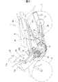
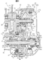
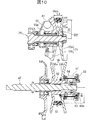
28 クランク軸(入力軸)
47 変速軸(出力軸)
55 駆動プーリ
55a 駆動側固定プーリ半体
55b 駆動側可動プーリ半体
55c ストッパ部(駆動側ストッパ)
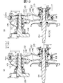
56 従動プーリ
56a 従動側固定プーリ半体
56b 従動側可動プーリ半体
57 Vベルト
58 カムプレート
61 ウェイト
62 スライドカラー
63 ボス部
63a スライド溝
64 ガイドピン(従動側ストッパ)
65 ばね受け部材(従動側ストッパ)
Claims (11)
- 入力軸に装着された巻き掛け径可変式の駆動プーリと該入力軸と平行な出力軸に装着された巻き掛け径可変式の従動プーリとをVベルトにより連結してなるVベルト式無段変速装置において、上記駆動プーリを、上記入力軸に軸方向移動不能に固定された駆動側固定プーリ半体と、該駆動側固定プーリ半体に対して軸方向に移動可能に装着され、上記入力軸の回転に伴って上記駆動側固定プーリ半体側に移動される駆動側可動プーリ半体とを備えたものとし、上記従動プーリを、上記出力軸に軸方向移動不能に固定された従動側固定プーリ半体と、該従動側固定プーリ半体に対して軸方向に移動可能に装着され、かつ該従動側固定プーリ半体側にばねで付勢された従動側可動プーリ半体とを備えたものとし、該従動側可動プーリ半体の上記従動側固定プーリ半体との間隔が大きくなる方向への移動を規制する従動側ストッパと、上記駆動側可動プーリ半体の上記駆動側固定プーリ半体との間隔が小さくなる方向への移動を規制する駆動側ストッパとを設け、上記従動側ストッパと可動側ストッパとを、同一のVベルトを用いて運転している状態における運転時間の増加に伴って、上記従動側可動プーリ半体の移動が従動側ストッパで規制されている状態から上記駆動側プーリ半体の移動が駆動側ストッパで規制されている状態に移行可能に構成したことを特徴とするVベルト式無段変速装置。
- 請求項1において、上記従動側ストッパが、上記従動側可動プーリ半体と上記出力軸との間に設けられていることを特徴とするVベルト式無段変速装置。
- 請求項2において、上記従動側ストッパが、上記従動側可動プーリ半体のボス部と上記出力軸との間に設けられていることを特徴とするVベルト式無段変速装置。
- 請求項3において、上記従動側ストッパが、上記従動側可動プーリ半体のボス部と上記出力軸に装着された上記従動側固定プーリ半体のスライドカラーとの間に設けられていることを特徴とするVベルト式無段変速装置。
- 請求項4において、上記従動側ストッパが、上記従動側可動プーリ半体のボス部と上記スライドカラーの外端部との間に設けられていることを特徴とするVベルト式無段変速装置。
- 請求項5において、上記従動側ストッパが、上記従動側可動プーリ半体のボス部の外端面と、上記スライドカラーの外端部に固定された上記ばねのばね受け部材で構成されていることを特徴とするVベルト式無段変速装置。
- 請求項2において、上記従動側ストッパが、上記従動側可動プーリ半体のボス部の外端面と上記出力軸に固定された上記ばねのばね受け部材とで構成されていることを特徴とするVベルト式無段変速装置。
- 請求項2において、上記従動側可動プーリ半体は、上記出力軸に植設されたガイドピンを該従動側可動プーリ半体のスライド溝に係合させることにより軸方向に移動可能でかつ出力軸と共に回転するようになっており、上記従動側ストッパは、上記従動側可動プーリ半体のスライド溝と上記ガイドピンとで構成されていることを特徴とするVベルト式無段変速装置。
- 請求項1において、上記駆動側ストッパが、上記駆動側可動プーリ半体と上記入力軸との間に設けられていることを特徴とするVベルト式無段変速装置。
- 請求項9において、上記駆動側可動プーリと上記入力軸に装着されたカムプレートとの間に設けられ、径方向外側への移動で上記駆動側可動プーリを移動させるウェイトを備え、上記駆動側ストッパが、上記ウェイトの径方向位置を規制することにより構成されていることを特徴とするVベルト式無段変速装置。
- 請求項10において、上記駆動側ストッパが、上記駆動側可動プーリ半体の外縁部に形成されたストッパ部と上記ウェイトとで構成されていることを特徴とするVベルト式無段変速装置。
Applications Claiming Priority (3)
| Application Number | Priority Date | Filing Date | Title |
|---|---|---|---|
| JP2002327181 | 2002-11-11 | ||
| JP2002327181 | 2002-11-11 | ||
| PCT/JP2003/007238 WO2004044457A1 (ja) | 2002-11-11 | 2003-06-06 | Vベルト式無段変速装置 |
Publications (2)
| Publication Number | Publication Date |
|---|---|
| JPWO2004044457A1 JPWO2004044457A1 (ja) | 2006-03-16 |
| JP4181123B2 true JP4181123B2 (ja) | 2008-11-12 |
Family
ID=32310512
Family Applications (1)
| Application Number | Title | Priority Date | Filing Date |
|---|---|---|---|
| JP2004551186A Expired - Lifetime JP4181123B2 (ja) | 2002-11-11 | 2003-06-06 | Vベルト式無段変速装置 |
Country Status (9)
| Country | Link |
|---|---|
| EP (1) | EP1564441B1 (ja) |
| JP (1) | JP4181123B2 (ja) |
| CN (1) | CN100443773C (ja) |
| AU (1) | AU2003242032A1 (ja) |
| BR (1) | BRPI0314197B1 (ja) |
| ES (1) | ES2667252T3 (ja) |
| MY (1) | MY180790A (ja) |
| TW (1) | TWI226416B (ja) |
| WO (1) | WO2004044457A1 (ja) |
Families Citing this family (8)
| Publication number | Priority date | Publication date | Assignee | Title |
|---|---|---|---|---|
| JP4588412B2 (ja) * | 2004-10-22 | 2010-12-01 | 本田技研工業株式会社 | Vベルト式自動変速機 |
| JP5030413B2 (ja) | 2005-11-07 | 2012-09-19 | ヤマハ発動機株式会社 | 鞍乗型車両 |
| JP2008039177A (ja) | 2006-07-12 | 2008-02-21 | Yamaha Motor Co Ltd | ベルト式無段変速機、鞍乗型車両、およびベルト式無段変速機のシーブの製造方法 |
| DE102009051250A1 (de) * | 2008-11-03 | 2010-05-06 | Luk Lamellen Und Kupplungsbau Beteiligungs Kg | Scheibensatzanordnug für ein Ketten-CVT mit einer funktionsoptimierten Scheibensatzkontur |
| WO2011029417A1 (de) | 2009-09-10 | 2011-03-17 | Schaeffler Technologies Gmbh & Co. Kg | Scheibensatzanordnung für ein ketten-cvt |
| FR3084714B1 (fr) * | 2018-08-01 | 2020-07-03 | Continental Automotive France | Poulie a flasque a ecartement variable pour variateur de vitesse |
| JP7061205B2 (ja) * | 2018-12-05 | 2022-04-27 | 本田技研工業株式会社 | ベルト式無段変速装置 |
| CN110848350B (zh) * | 2019-11-18 | 2021-02-09 | 淮阴工学院 | 一种势能驱动下的遇阻式自动变矩装置 |
Family Cites Families (11)
| Publication number | Priority date | Publication date | Assignee | Title |
|---|---|---|---|---|
| US3962928A (en) * | 1975-01-14 | 1976-06-15 | Guy Beaudoin | Variable diameter pulley with shim means compensating for belt wear |
| JPH0343484Y2 (ja) * | 1985-09-03 | 1991-09-11 | ||
| JPS63171753A (ja) * | 1987-01-05 | 1988-07-15 | Rohm Co Ltd | フ−プ材加工工程間のバツフア装置 |
| JP2511297Y2 (ja) * | 1987-04-29 | 1996-09-25 | スズキ株式会社 | Vベルト無段変速装置 |
| JPH08178004A (ja) | 1994-12-27 | 1996-07-12 | Suzuki Motor Corp | Vベルト式自動変速装置 |
| JPH08178003A (ja) | 1994-12-27 | 1996-07-12 | Suzuki Motor Corp | Vベルト式自動変速装置 |
| JP3365697B2 (ja) * | 1995-02-28 | 2003-01-14 | 本田技研工業株式会社 | Vベルト式変速装置 |
| CN2225407Y (zh) * | 1995-05-26 | 1996-04-24 | 三阳工业股份有限公司 | 机车用无级变速机构主动侧滑轮组 |
| DE19946336B4 (de) * | 1998-10-02 | 2013-04-25 | Schaeffler Technologies AG & Co. KG | Kontinuierlich verstellbarer Umschlingungsmitteltrieb |
| JP3709971B2 (ja) * | 2000-03-07 | 2005-10-26 | 本田技研工業株式会社 | 車両用vベルト式自動変速機 |
| JP2002019682A (ja) * | 2000-07-05 | 2002-01-23 | Yamaha Motor Co Ltd | 自動二輪車用エンジンの動力伝達装置 |
-
2003
- 2003-06-06 AU AU2003242032A patent/AU2003242032A1/en not_active Abandoned
- 2003-06-06 BR BRPI0314197A patent/BRPI0314197B1/pt active IP Right Grant
- 2003-06-06 ES ES03730860.8T patent/ES2667252T3/es not_active Expired - Lifetime
- 2003-06-06 EP EP03730860.8A patent/EP1564441B1/en not_active Expired - Lifetime
- 2003-06-06 JP JP2004551186A patent/JP4181123B2/ja not_active Expired - Lifetime
- 2003-06-06 CN CNB038208687A patent/CN100443773C/zh not_active Expired - Lifetime
- 2003-06-06 WO PCT/JP2003/007238 patent/WO2004044457A1/ja active Application Filing
- 2003-11-07 MY MYPI20034267A patent/MY180790A/en unknown
- 2003-11-11 TW TW092131523A patent/TWI226416B/zh not_active IP Right Cessation
Also Published As
| Publication number | Publication date |
|---|---|
| EP1564441B1 (en) | 2018-04-11 |
| JPWO2004044457A1 (ja) | 2006-03-16 |
| MY180790A (en) | 2020-12-09 |
| CN100443773C (zh) | 2008-12-17 |
| TWI226416B (en) | 2005-01-11 |
| AU2003242032A1 (en) | 2004-06-03 |
| EP1564441A1 (en) | 2005-08-17 |
| BRPI0314197B1 (pt) | 2016-01-19 |
| ES2667252T3 (es) | 2018-05-10 |
| BR0314197A (pt) | 2005-07-26 |
| TW200419091A (en) | 2004-10-01 |
| EP1564441A4 (en) | 2008-04-23 |
| CN1678844A (zh) | 2005-10-05 |
| WO2004044457A1 (ja) | 2004-05-27 |
Similar Documents
| Publication | Publication Date | Title |
|---|---|---|
| JP4410817B2 (ja) | エンジン | |
| JP5030413B2 (ja) | 鞍乗型車両 | |
| US7398753B2 (en) | Engine with built-in continuously variable transmission | |
| JP5041355B2 (ja) | Vベルト式無段変速機、鞍乗型車両、及びvベルト式無段変速機の製造方法 | |
| US7201686B2 (en) | Saddle-type vehicle and engine | |
| US7311623B2 (en) | Engine incorporating a V-belt type continuously variable transmission | |
| CA2506815A1 (en) | Power transmission system of vehicle | |
| US8147370B2 (en) | Power unit for motorcycle | |
| JP4181123B2 (ja) | Vベルト式無段変速装置 | |
| US8016094B2 (en) | Centrifugal clutch and straddle type vehicle including the centrifugal clutch | |
| JP5648578B2 (ja) | 多板式自動遠心クラッチ装置 | |
| US7631718B2 (en) | Saddle-type vehicle and engine | |
| JP3993170B2 (ja) | エンジンのクラッチ機構潤滑構造 | |
| JP4181051B2 (ja) | エンジン | |
| JP2003293786A (ja) | エンジン | |
| JP4177687B2 (ja) | 頭上カム型エンジン | |
| JP2006347187A (ja) | 鞍乗型車両用エンジン及びこれを備えた鞍乗型車両 | |
| JP2003293787A (ja) | エンジン | |
| JP2004338675A (ja) | エンジンの動力伝達装置 | |
| JP2003293912A (ja) | エンジンのキック装置 | |
| JP2005291473A (ja) | クラッチの潤滑装置 |
Legal Events
| Date | Code | Title | Description |
|---|---|---|---|
| A521 | Request for written amendment filed |
Free format text: JAPANESE INTERMEDIATE CODE: A523 Effective date: 20060120 |
|
| A521 | Request for written amendment filed |
Free format text: JAPANESE INTERMEDIATE CODE: A523 Effective date: 20060214 |
|
| A131 | Notification of reasons for refusal |
Free format text: JAPANESE INTERMEDIATE CODE: A131 Effective date: 20080325 |
|
| A521 | Request for written amendment filed |
Free format text: JAPANESE INTERMEDIATE CODE: A523 Effective date: 20080519 |
|
| TRDD | Decision of grant or rejection written | ||
| A01 | Written decision to grant a patent or to grant a registration (utility model) |
Free format text: JAPANESE INTERMEDIATE CODE: A01 Effective date: 20080826 |
|
| A01 | Written decision to grant a patent or to grant a registration (utility model) |
Free format text: JAPANESE INTERMEDIATE CODE: A01 |
|
| A61 | First payment of annual fees (during grant procedure) |
Free format text: JAPANESE INTERMEDIATE CODE: A61 Effective date: 20080828 |
|
| R150 | Certificate of patent or registration of utility model |
Ref document number: 4181123 Country of ref document: JP Free format text: JAPANESE INTERMEDIATE CODE: R150 |
|
| FPAY | Renewal fee payment (event date is renewal date of database) |
Free format text: PAYMENT UNTIL: 20110905 Year of fee payment: 3 |
|
| FPAY | Renewal fee payment (event date is renewal date of database) |
Free format text: PAYMENT UNTIL: 20120905 Year of fee payment: 4 |
|
| R250 | Receipt of annual fees |
Free format text: JAPANESE INTERMEDIATE CODE: R250 |
|
| FPAY | Renewal fee payment (event date is renewal date of database) |
Free format text: PAYMENT UNTIL: 20130905 Year of fee payment: 5 |
|
| R250 | Receipt of annual fees |
Free format text: JAPANESE INTERMEDIATE CODE: R250 |
|
| R250 | Receipt of annual fees |
Free format text: JAPANESE INTERMEDIATE CODE: R250 |
|
| R250 | Receipt of annual fees |
Free format text: JAPANESE INTERMEDIATE CODE: R250 |
|
| R250 | Receipt of annual fees |
Free format text: JAPANESE INTERMEDIATE CODE: R250 |
|
| R250 | Receipt of annual fees |
Free format text: JAPANESE INTERMEDIATE CODE: R250 |
|
| R250 | Receipt of annual fees |
Free format text: JAPANESE INTERMEDIATE CODE: R250 |
|
| R250 | Receipt of annual fees |
Free format text: JAPANESE INTERMEDIATE CODE: R250 |
|
| R250 | Receipt of annual fees |
Free format text: JAPANESE INTERMEDIATE CODE: R250 |
|
| R250 | Receipt of annual fees |
Free format text: JAPANESE INTERMEDIATE CODE: R250 |
|
| R250 | Receipt of annual fees |
Free format text: JAPANESE INTERMEDIATE CODE: R250 |
|
| R250 | Receipt of annual fees |
Free format text: JAPANESE INTERMEDIATE CODE: R250 |
|
| EXPY | Cancellation because of completion of term |