JP4181123B2 - V belt type continuously variable transmission - Google Patents
V belt type continuously variable transmission Download PDFInfo
- Publication number
- JP4181123B2 JP4181123B2 JP2004551186A JP2004551186A JP4181123B2 JP 4181123 B2 JP4181123 B2 JP 4181123B2 JP 2004551186 A JP2004551186 A JP 2004551186A JP 2004551186 A JP2004551186 A JP 2004551186A JP 4181123 B2 JP4181123 B2 JP 4181123B2
- Authority
- JP
- Japan
- Prior art keywords
- driven
- pulley half
- movable pulley
- stopper
- continuously variable
- Prior art date
- Legal status (The legal status is an assumption and is not a legal conclusion. Google has not performed a legal analysis and makes no representation as to the accuracy of the status listed.)
- Expired - Lifetime
Links
Images


Classifications
-
- F—MECHANICAL ENGINEERING; LIGHTING; HEATING; WEAPONS; BLASTING
- F16—ENGINEERING ELEMENTS AND UNITS; GENERAL MEASURES FOR PRODUCING AND MAINTAINING EFFECTIVE FUNCTIONING OF MACHINES OR INSTALLATIONS; THERMAL INSULATION IN GENERAL
- F16H—GEARING
- F16H9/00—Gearings for conveying rotary motion with variable gear ratio, or for reversing rotary motion, by endless flexible members
- F16H9/02—Gearings for conveying rotary motion with variable gear ratio, or for reversing rotary motion, by endless flexible members without members having orbital motion
- F16H9/04—Gearings for conveying rotary motion with variable gear ratio, or for reversing rotary motion, by endless flexible members without members having orbital motion using belts, V-belts, or ropes
- F16H9/12—Gearings for conveying rotary motion with variable gear ratio, or for reversing rotary motion, by endless flexible members without members having orbital motion using belts, V-belts, or ropes engaging a pulley built-up out of relatively axially-adjustable parts in which the belt engages the opposite flanges of the pulley directly without interposed belt-supporting members
- F16H9/16—Gearings for conveying rotary motion with variable gear ratio, or for reversing rotary motion, by endless flexible members without members having orbital motion using belts, V-belts, or ropes engaging a pulley built-up out of relatively axially-adjustable parts in which the belt engages the opposite flanges of the pulley directly without interposed belt-supporting members using two pulleys, both built-up out of adjustable conical parts
- F16H9/18—Gearings for conveying rotary motion with variable gear ratio, or for reversing rotary motion, by endless flexible members without members having orbital motion using belts, V-belts, or ropes engaging a pulley built-up out of relatively axially-adjustable parts in which the belt engages the opposite flanges of the pulley directly without interposed belt-supporting members using two pulleys, both built-up out of adjustable conical parts only one flange of each pulley being adjustable
-
- F—MECHANICAL ENGINEERING; LIGHTING; HEATING; WEAPONS; BLASTING
- F16—ENGINEERING ELEMENTS AND UNITS; GENERAL MEASURES FOR PRODUCING AND MAINTAINING EFFECTIVE FUNCTIONING OF MACHINES OR INSTALLATIONS; THERMAL INSULATION IN GENERAL
- F16H—GEARING
- F16H55/00—Elements with teeth or friction surfaces for conveying motion; Worms, pulleys or sheaves for gearing mechanisms
- F16H55/32—Friction members
- F16H55/52—Pulleys or friction discs of adjustable construction
- F16H55/56—Pulleys or friction discs of adjustable construction of which the bearing parts are relatively axially adjustable
-
- F—MECHANICAL ENGINEERING; LIGHTING; HEATING; WEAPONS; BLASTING
- F16—ENGINEERING ELEMENTS AND UNITS; GENERAL MEASURES FOR PRODUCING AND MAINTAINING EFFECTIVE FUNCTIONING OF MACHINES OR INSTALLATIONS; THERMAL INSULATION IN GENERAL
- F16H—GEARING
- F16H63/00—Control outputs from the control unit to change-speed- or reversing-gearings for conveying rotary motion or to other devices than the final output mechanism
- F16H63/02—Final output mechanisms therefor; Actuating means for the final output mechanisms
- F16H63/04—Final output mechanisms therefor; Actuating means for the final output mechanisms a single final output mechanism being moved by a single final actuating mechanism
- F16H63/06—Final output mechanisms therefor; Actuating means for the final output mechanisms a single final output mechanism being moved by a single final actuating mechanism the final output mechanism having an indefinite number of positions
- F16H63/067—Final output mechanisms therefor; Actuating means for the final output mechanisms a single final output mechanism being moved by a single final actuating mechanism the final output mechanism having an indefinite number of positions mechanical actuating means
-
- F—MECHANICAL ENGINEERING; LIGHTING; HEATING; WEAPONS; BLASTING
- F16—ENGINEERING ELEMENTS AND UNITS; GENERAL MEASURES FOR PRODUCING AND MAINTAINING EFFECTIVE FUNCTIONING OF MACHINES OR INSTALLATIONS; THERMAL INSULATION IN GENERAL
- F16H—GEARING
- F16H61/00—Control functions within control units of change-speed- or reversing-gearings for conveying rotary motion ; Control of exclusively fluid gearing, friction gearing, gearings with endless flexible members or other particular types of gearing
- F16H61/66—Control functions within control units of change-speed- or reversing-gearings for conveying rotary motion ; Control of exclusively fluid gearing, friction gearing, gearings with endless flexible members or other particular types of gearing specially adapted for continuously variable gearings
- F16H61/662—Control functions within control units of change-speed- or reversing-gearings for conveying rotary motion ; Control of exclusively fluid gearing, friction gearing, gearings with endless flexible members or other particular types of gearing specially adapted for continuously variable gearings with endless flexible members
- F16H2061/66295—Control functions within control units of change-speed- or reversing-gearings for conveying rotary motion ; Control of exclusively fluid gearing, friction gearing, gearings with endless flexible members or other particular types of gearing specially adapted for continuously variable gearings with endless flexible members characterised by means for controlling the geometrical interrelationship of pulleys and the endless flexible member, e.g. belt alignment or position of the resulting axial pulley force in the plane perpendicular to the pulley axis
Description
本発明は、回転力が伝達される入力軸に装着された駆動プーリと出力軸に装着された従動プーリとをVベルトにより連結してなるVベルト式無段変速装置に関する。 The present invention relates to a V-belt type continuously variable transmission in which a drive pulley attached to an input shaft to which rotational force is transmitted and a driven pulley attached to an output shaft are connected by a V-belt.
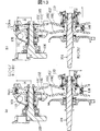
例えば、スクータ型自動二輪車では、エンジン動力を後輪に伝達する動力伝達機構としてVベルト式無段変速装置を採用する場合がある。この種のVベルト式無段変速装置では、図13(a),(b)に示すように、クランク軸(入力軸)100に装着され、駆動側固定プーリ半体101,駆動側可動プーリ半体102を有する駆動プーリ103と、出力軸104に装着され、従動側固定プーリ半体105,従動側可動プーリ半体106を有する従動プーリ107とをVベルト108により連結した構造が一般的である。
For example, a scooter type motorcycle may employ a V-belt continuously variable transmission as a power transmission mechanism that transmits engine power to a rear wheel. In this type of V-belt type continuously variable transmission, as shown in FIGS. 13A and 13B, a crankshaft (input shaft) 100 is mounted, and a driving side fixed
上記Vベルト式無段変速装置では、エンジン回転が上昇するにつれてウェイト109が遠心力で駆動側可動プーリ半体102を固定プーリ半体101側に移動させ、これに伴って従動プーリ107の従動側可動プーリ半体106がばね110を圧縮しつつ固定プーリ半体105から離れる方向に移動する。これにより減速比は駆動プーリ103の巻き掛け径が大きくなるとともに、従動プーリ107の巻き掛け径が小さくなり、最小減速比となるトップ時減速比となる。この場合、上記ウェイト109の径方向位置を規制することにより駆動側可動プーリ半体102の軸方向位置をトップ時位置に規制するのが一般的である。(例えば、特許文献1,特許文献2参照)
ところが、上記従来装置のように駆動プーリ側でトップ時減速比を規制する構造とした場合には、Vベルトが磨耗した分だけ駆動プーリの巻き掛け径が小さくなり、これに伴って従動プーリ側の巻き掛け径は大きくなることから、減速比がトップ時減速比からロー時減速比側にずれ、最高速度が低下するという問題がある。 However, when the top pulley reduction ratio is controlled on the drive pulley side as in the above-described conventional device, the winding diameter of the drive pulley is reduced by the amount of wear of the V belt, and accordingly the driven pulley side Since the wrapping diameter increases, the speed reduction ratio shifts from the top speed reduction ratio to the low speed reduction ratio, and the maximum speed is lowered.
例えば、図13(a),(b)に示すように、例えばある距離D2km走行した時にVベルト108の磨耗によって上幅寸法が新品時のL1からL1´に小さくなった場合、この磨耗した分だけ駆動プーリ103の巻き掛け径はトップ時位置のR1からR1´と小さくなるとともに、従動プーリ107の巻き掛け径がR2からR2´と大きくなり、減速比がR2/R1からR2´/R1´と大きくなる。その結果、同じエンジンでのトップ時の車速が低下することから、磨耗量が許容範囲であってもVベルトを交換しなければならず、交換時期の延長を図る上での改善が要請されている。
For example, as shown in FIGS. 13 (a) and 13 (b), when the upper width dimension is reduced from L1 to L1 ′ due to wear of the V-
本発明は、上記実情に鑑みてなされたもので、Vベルトの磨耗による減速比のずれを抑制して同じエンジン回転数での車速を確保することができ、Vベルトの交換時期を延長できるVベルト式無段変速装置を提供することを目的としている。 The present invention has been made in view of the above circumstances, and can suppress the shift of the reduction ratio due to wear of the V-belt, can ensure the vehicle speed at the same engine speed, and can extend the replacement period of the V-belt. An object of the present invention is to provide a belt type continuously variable transmission.
請求項1の発明は、入力軸に装着された巻き掛け径可変式の駆動プーリと該入力軸と平行な出力軸に装着された巻き掛け径可変式の従動プーリとをVベルトにより連結してなるVベルト式無段変速装置において、上記駆動プーリを、上記入力軸に軸方向移動不能に固定された駆動側固定プーリ半体と、該駆動側固定プーリ半体に対して軸方向に移動可能に装着され、上記入力軸の回転に伴って上記駆動側固定プーリ半体側に移動される駆動側可動プーリ半体とを備えたものとし、上記従動プーリを、上記出力軸に軸方向移動不能に固定された従動側固定プーリ半体と、該従動側固定プーリ半体に対して軸方向に移動可能に装着され、かつ該従動側固定プーリ半体側にばねで付勢された従動側可動プーリ半体とを備えたものとし、該従動側可動プーリ半体の上記従動側固定プーリ半体との間隔が大きくなる方向への移動を規制する従動側ストッパと、上記駆動側可動プーリ半体の上記駆動側固定プーリ半体との間隔が小さくなる方向への移動を規制する駆動側ストッパとを設け、上記従動側ストッパと可動側ストッパとを、同一のVベルトを用いて運転している状態における運転時間の増加に伴って、上記従動側可動プーリ半体の移動が従動側ストッパで規制されている状態から上記駆動側プーリ半体の移動が駆動側ストッパで規制されている状態に移行可能に構成したことを特徴としている。 According to the first aspect of the present invention, a variable winding diameter driving pulley mounted on an input shaft and a variable winding diameter driven pulley mounted on an output shaft parallel to the input shaft are connected by a V-belt. In the V-belt type continuously variable transmission, the drive pulley is fixed to the input shaft so as not to move in the axial direction, and is movable in the axial direction with respect to the drive-side fixed pulley half. And a drive-side movable pulley half that is moved to the drive-side fixed pulley half as the input shaft rotates, so that the driven pulley cannot be moved axially on the output shaft. A fixed driven-side fixed pulley half, and a driven-side movable pulley half that is attached to the driven-side fixed pulley half so as to be movable in the axial direction and is biased by a spring toward the driven-side fixed pulley half. With a body, the driven side movable The distance between the driven side stopper that restricts the movement of the pulley half in the direction in which the distance between the driven side fixed pulley half and the driven side fixed pulley half increases and the distance between the driving side movable pulley half and the driving side fixed pulley half are small. A drive-side stopper that restricts movement in the direction in which the driven-side stopper and the movable-side stopper are operated with the same V-belt. It is characterized in that the movement of the movable pulley half can be shifted from the state where the movement of the driven pulley half is restricted by the driven side stopper to the state where the movement of the driving side pulley half is restricted by the driving side stopper.
請求項2の発明は、請求項1において、上記従動側ストッパが、上記従動側可動プーリ半体と上記出力軸との間に設けられていることを特徴としている。
The invention of
請求項3の発明は、請求項2において、上記従動側ストッパが、上記従動側可動プーリ半体のボス部と上記出力軸との間に設けられていることを特徴としている。
The invention of claim 3 is characterized in that, in
請求項4の発明は、請求項3において、上記従動側ストッパが、上記従動側可動プーリ半体のボス部と上記出力軸に装着された上記従動側固定プーリ半体のスライドカラーとの間に設けられていることを特徴としている。 According to a fourth aspect of the present invention, in the third aspect , the driven-side stopper is provided between the boss portion of the driven-side movable pulley half and the slide collar of the driven-side fixed pulley half mounted on the output shaft. It is characterized by being provided.
請求項5の発明は、請求項4において、上記従動側ストッパが、上記従動側可動プーリ半体のボス部と上記スライドカラーの外端部との間に設けられていることを特徴としている。 The invention of claim 5 is characterized in that, in claim 4 , the driven-side stopper is provided between a boss portion of the driven-side movable pulley half and an outer end portion of the slide collar.
請求項6の発明は、請求項5において、上記従動側ストッパが、上記従動側可動プーリ半体のボス部の外端面と、上記スライドカラーの外端部に固定された上記ばねのばね受け部材とで構成されていることを特徴としている。 A sixth aspect of the present invention is the spring receiving member of the spring according to the fifth aspect, wherein the driven side stopper is fixed to the outer end surface of the boss portion of the driven side movable pulley half and the outer end portion of the slide collar. It is characterized by comprising.
請求項7の発明は、請求項2において、上記従動側ストッパが、上記従動側可動プーリ半体のボス部の外端面と上記出力軸に固定された上記ばねのばね受け部材とで構成されていることを特徴としている。
The invention according to claim 7 is the invention according to
請求項8の発明は、請求項2において、上記従動側可動プーリ半体は、上記出力軸に植設されたガイドピンを該従動側可動プーリ半体のスライド溝に係合させることにより軸方向に移動可能でかつ出力軸と共に回転するようになっており、上記従動側ストッパは、上記従動側可動プーリ半体のスライド溝と上記ガイドピンとで構成されていることを特徴としている。 According to an eighth aspect of the present invention, in the second aspect , the driven movable pulley half is axially moved by engaging a guide pin implanted in the output shaft with a slide groove of the driven movable pulley half. The driven-side stopper is composed of a slide groove of the driven-side movable pulley half and the guide pin.
請求項9の発明は、請求項1において、上記駆動側ストッパが、上記駆動側可動プーリ半体と上記入力軸との間に設けられていることを特徴としている。 A ninth aspect of the invention is characterized in that, in the first aspect , the driving side stopper is provided between the driving side movable pulley half and the input shaft.
請求項10の発明は、請求項9において、上記駆動側可動プーリと上記入力軸に装着されたカムプレートとの間に設けられ、径方向外側への移動で上記駆動側可動プーリを移動させるウェイトを備え、上記駆動側ストッパが、上記ウェイトの径方向位置を規制することにより構成されていることを特徴としている。 A tenth aspect of the present invention is the weight according to the ninth aspect, wherein the weight is provided between the driving-side movable pulley and the cam plate attached to the input shaft, and moves the driving-side movable pulley by moving radially outward. The drive side stopper is configured by restricting the radial position of the weight.
請求項11の発明は、請求項10において、上記駆動側ストッパが、上記駆動側可動プーリ半体の外縁部に形成されたストッパ部と上記ウェイトとで構成されていることを特徴としている。 An eleventh aspect of the invention is characterized in that, in the tenth aspect , the driving side stopper is composed of a stopper portion formed on an outer edge portion of the driving side movable pulley half and the weight.
本発明に係るVベルト式無段変速装置では、従動プーリ側の従動側可動プーリ半体を最小巻き掛け径となる位置に規制し、駆動プーリ側の駆動側可動プーリ半体を補正最大巻き掛け径となる位置に規制したので、運転開始からの運転時間の増加に伴ってVベルトが磨耗すると、従動プーリの間隔は変化せずに駆動側可動プーリが規制位置に移動して駆動プーリ間隔が狭くなり、巻き掛け径が大きくなることから減速比が小さくなる方向に変化する。またVベルトの磨耗量の増加に伴なって駆動側可動プーリが上記規制位置に達した後は、上記磨耗量のさらなる増加に伴なって、減速比が増大する方向に変化する。このように運転時間の増加に伴って減速比が一旦小さくなる方向に変化した後、元の減速比に戻る方向に変化し、その後に減速比が増加する方向に変化することとなり、Vベルトの磨耗量が相当大きくなって始めて出力軸回転数が下限値に低下する。その結果Vベルト In the V-belt type continuously variable transmission according to the present invention, the driven movable pulley half on the driven pulley side is restricted to a position where the minimum winding diameter is obtained, and the corrected movable pulley half on the drive pulley side is corrected to the maximum winding Since the V-belt is worn as the operation time increases from the start of operation, the driven pulley is moved to the restricted position without changing the driven pulley interval, and the drive pulley interval is increased. Since the winding diameter becomes narrower and the winding diameter becomes larger, the speed reduction ratio changes in a smaller direction. Further, after the drive side movable pulley reaches the restriction position as the wear amount of the V-belt increases, the reduction ratio changes in a direction that increases as the wear amount further increases. In this way, as the operating time increases, the speed reduction ratio temporarily changes in the direction of decreasing, then returns to the original speed reduction ratio, and then changes in the direction of increase of the speed reduction ratio. The output shaft speed decreases to the lower limit value only after the amount of wear becomes considerably large. As a result V belt
以下、本発明の実施の形態を添付図面に基づいて説明する。 Hereinafter, embodiments of the present invention will be described with reference to the accompanying drawings.
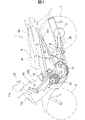
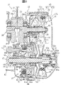
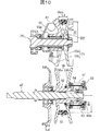
図1ないし図6は、本発明の一実施形態によるVベルト式無段変速装置を説明するための図であり、図1は本実施形態のVベルト式無段変速装置が搭載された自動二輪車の左側面図、図2はVベルト式無段変速装置を備えたエンジンユニットの断面平面図、図3はVベルト式無段変速装置の断面平面図、図4,図5,図6はそれぞれVベルトの磨耗による巻き掛け径の変化を示す断面図である。なお、本実施形態でいう前後,左右とはシートに着座した状態で見た前後,左右を意味する。 FIGS. 1 to 6 are views for explaining a V-belt type continuously variable transmission according to an embodiment of the present invention. FIG. 1 is a motorcycle equipped with the V-belt continuously variable transmission of this embodiment. 2 is a cross-sectional plan view of an engine unit equipped with a V-belt type continuously variable transmission, FIG. 3 is a cross-sectional plan view of the V-belt type continuously variable transmission, and FIGS. It is sectional drawing which shows the change of the winding diameter by abrasion of V belt. Note that front and rear and left and right as used in this embodiment mean front and rear and left and right as viewed in a seated state.
図1において、1は自動二輪車を示しており、これは車体フレーム1aの前端に固着されたヘッドパイプ3により前輪4が軸支されたフロントフォーク5を左右回動可能に枢支し、中央部に固着されたリヤアームブラケット6より後輪7が軸支されたリヤアーム8を上下揺動可能に枢支し、上記車体フレーム1aの上部に運転者用シート部9aと後部乗員用シート部9bとからなるシート9を配置した概略構造を有している。
In FIG. 1, reference numeral 1 denotes a motorcycle, which pivotally supports a front fork 5 on which a front wheel 4 is pivotally supported by a head pipe 3 fixed to a front end of a vehicle body frame 1a so as to be rotatable left and right. A
上記車体フレーム1aはヘッドパイプ3から斜め下方に延びる左,右のダウンチューブ1bと該各ダウンチューブ1bの後端に続いて斜め上方に延びる左,右のアッパチューブ1cと、ダウンチューブ1bとアッパチューブ1cとに前後方向に架け渡して接合された左右のシートレール1dとからなる。また上記車体フレーム1aはフロントカバー10a,レッグシールド10b,サイドカバー10c等からなる樹脂製の車体カバー10により覆われている。
The vehicle body frame 1a includes a left and right down tube 1b extending obliquely downward from the head pipe 3, a left and right upper tube 1c extending obliquely upward following the rear end of each down tube 1b, a down tube 1b and an upper. It consists of left and right seat rails 1d that are bridged and joined to the tube 1c in the front-rear direction. The vehicle body frame 1a is covered with a resin
上記フロントフォーク5の上端には操向ハンドル11が固定されており、該操向ハンドル11はハンドルカバー11aにより覆われている。また上記リヤアーム8とリヤアームブラケット6との間にはリヤクッション12が架設されている。
A
上記車体フレーム1aのダウンチューブ1bにエンジンユニット2が懸架支持されている。このエンジンユニット2は気筒軸線Aを前方に約45度傾斜させて搭載された空冷式4サイクル単気筒エンジン15とVベルト式無段変速装置16と湿式多板式遠心クラッチ機構17及び減速歯車機構18とを備えている。
The
上記エンジン15は、シリンダブロック19の上合面にシリンダヘッド20を接続するとともに、上記シリンダブロック19の下合面にクランク軸28が収納されたクランクケース22を接続した概略構造となっている。
The
上記シリンダヘッド20の後面には燃焼凹部20aに連通する吸気ポート(不図示)が開口しており、該吸気ポートには吸気管23aを介して気化器23が接続されている。また上記シリンダヘッド20の前面には燃焼凹部20aに連通する排気ポート(不図示)が開口しており、該排気ポートには排気管24が接続されている。この排気管24はエンジン15の後ろ下方に延びた後、右側方を通って斜め後方に延びており、上記後輪7の右側方に配設されたマフラ25に接続されている。上記燃焼凹部20a内には点火プラグ30が挿入されている。
An intake port (not shown) communicating with the combustion recess 20a is opened on the rear surface of the
上記シリンダブロック19の左側部にはクランクケース22内とシリンダヘッド20内とを連通するチェーン室19aが形成されており、該チェーン室19aには上記クランク軸28によりカム軸31を回転駆動するタイミングチェーン34が配設されており、このカム軸31により不図示の吸気バルブ,排気バルブが開閉駆動される。
A
上記シリンダブロック19のシリンダボア内にはピストン26が摺動自在に挿入配置されている。該ピストン26にはコンロッド27の小端部27bが連結され、該コンロッド27の大端部27aは上記クランク軸28の左右のクランクアーム28a,28b間に嵌装されたクランクピン29に連結されている。
A
上記クランク軸28の後方には変速軸47が該クランク軸28と平行に配置されており、該変速軸47の軸方向左側には駆動軸48が同軸をなすよう配置されている。この駆動軸48の左端部には駆動スプロケット49が装着されており、該駆動スプロケット49はチェーン50を介して上記後輪7の従動スプロケット51に連結されている。
A
上記クランク軸28の左側端部には発電機42が装着されている。この発電機42はクランク軸28にテーパ嵌合されたスリーブ43にロータ42aを固着するとともに、該ロータ42aに対向するステータ42bを発電機ケース44に固定した構造となっている。
A
上記クランクケース22はクランク軸方向に左側の第1ケース40と右側の第2ケース41とに分割されている。この第1ケース40のクランク軸方向外側に上記発電機42を収容する発電機ケース44が着脱可能に装着されており、上記第2ケース41のクランク軸方向外側に上記Vベルト式無段変速装置16を収容する変速機ケース45が装着されている。
The
上記遠心クラッチ機構17は湿式多板式のもので、碗状のアウタクラッチ83を上記変速軸47に共に回転するようにスプライン嵌合させ、該アウタクラッチ83の軸方向内側にインナクラッチ84を同軸配置し、該インナクラッチ84を上記変速軸47に回転自在に装着された一次減速小ギヤ74に共に回転するようにスプライン嵌合させた概略構造を有している。
The centrifugal
上記アウタクラッチ83内には複数枚のアウタクラッチ板85が配置され、その両端に位置するように2枚の押圧プレート86,86が配置され、両者85,86は該アウタクラッチ83と共に回転するように該アウタクラッチ83に係止されている。また上記アウタクラッチ板85及び押圧プレート86の間にはインナクラッチ板87が配置され、該各インナクラッチ板87は上記インナクラッチ84と共に回転するように該インナクラッチ84の外周に係止されている。
In the outer clutch 83, a plurality of outer clutch plates 85 are arranged, and two pressing plates 86, 86 are arranged so as to be positioned at both ends thereof, and both 85, 86 rotate together with the
上記アウタクラッチ83の内側にはカム面83aが形成されており、該カム面83aと上記外側の押圧プレート86との間にはウェイト88が配設されている。このウェイト88はアウタクラッチ83の遠心力により半径方向外側に移動するに伴ってカム面83aによりクラッチ接続方向に移動し、押圧プレート86を押圧移動させてアウタ,インナクラッチ板85,86同士を接続状態とする。なお、図2,図3において、遠心クラッチ機構17の軸線より上側は遮断状態を、下側は接続状態を示している。
A cam surface 83 a is formed inside the outer clutch 83, and a
上記減速歯車機構18は、上記変速軸47と平行に減速軸52を配設するとともに、該変速軸47に上述の一次減速小ギヤ74を相対回転可能に装着し、上記減速軸52に一次減速小ギヤ74に噛合する一次減速大ギヤ75を結合し、上記減速軸52に二次減速小ギヤ52aを一体形成するとともに、上記駆動軸48に二次減速小ギヤ52aに噛合する二次減速大ギヤ48aを一体形成した構造となっている。
The speed
上記駆動軸48は変速軸47と同一軸線上に配設されている。この駆動軸48の右端部には上記変速軸47の左端部が挿入される支持孔48bが凹設されており、該支持孔48b内に装着された軸受76を介して該駆動軸48の右端部は変速軸47により軸支されている。
The
上記変速機ケース45は、上記クランクケース22とは独立して形成された略密閉構造のものであり、右側方から見て、上記クランクケース22の上側の大部分を覆う楕円形状を有している。上記変速機ケース45は、クランク軸方向外側に開口する有底箱状のケース本体45aと該ケース本体45aの開口を気密に閉塞する蓋体45bとからなり、ボルト70により上記第2ケース41に共締め固定されている。上記ケース本体45aの底壁45cと第2ケース41との間には隙間aが設けられており、この隙間aによりエンジン15からの熱が変速機ケース45に伝わるのを抑制している。
The
上記第2ケース41の軸方向の外側には遠心クラッチ機構17を出し入れできる大きさを有する開口41eが形成されている。この開口41eはクラッチカバー71により気密に閉塞されており、該クラッチカバー71はボルト72により上記第2ケース41の開口縁部に着脱可能に締め付け固定されている。これにより変速機ケース45を上記Vベルト式無段変速装置16の従動プーリ56とともに取り外し、クラッチカバー71を外すことによって遠心クラッチ機構17を変速軸47とともに取り外せるようになっている。
An opening 41e having a size that allows the centrifugal
上記Vベルト式無段変速装置16は、上記クランク軸(入力軸)28の右外端部に駆動プーリ55を装着するとともに、上記変速軸(出力軸)47の右外端部に従動プーリ56を装着し、該両プーリ55,56にVベルト57を巻回して連結した構造となっている。
The V-belt type continuously
上記Vベルト57は耐熱性,耐久性を有する樹脂製のものであり、横H形状の多数の樹脂ブロック57aを並べて配置し、これらを耐熱ゴム製の環状の一対の連結部材57bで連結したものである。なお、上記Vベルトとしてゴム製のものを採用することも可能である。
The V-
上記駆動プーリ55は、上記クランク軸28の右端部に固定された駆動側固定プーリ半体55aと、該固定プーリ半体55aのクランク軸方向内側に軸方向にスライド可能にかつスライドカラー59を介してクランク軸28と共に回転するように配設された駆動側可動プーリ半体55bとを有している。
The
上記駆動側可動プーリ半体55bのクランク軸方向内側にはカムプレート58が配設されている。このカムプレート58,スライドカラー59はクランク軸28の右端部にスプライン嵌合により装着され、これらの軸方向外側に上記駆動側固定プーリ半体55aが装着され、ロックナット60により締め付け固定されている。上記スライドカラー59上に上記駆動側可動プーリ半体55bの軸心部に一体形成された円筒状のボス部55dが軸方向に移動可能に装着されている。上記駆動側可動プーリ半体55bと上記カムプレート58との間には円筒形のウェイト61が配設されている。
A
上記従動プーリ56は、上記変速軸47の右外端部に固定された従動側固定プーリ半体56aと、該固定プーリ半体56aのクランク軸方向外側に軸方向にスライド可能に配設された従動側可動プーリ半体56bとを有している。
The driven
上記従動側固定プーリ半体56aの軸心部には円筒状のスライドカラー62が固着されており、該スライドカラー62は変速軸47にスプライン嵌合により装着されている。このスライドカラー62上に上記従動側可動プーリ半体56bの軸心部に固着された円筒状のボス部63が軸方向に移動可能に装着されている。
A
上記ボス部63には軸方向に延びる複数のスライド溝63aが形成されており、該スライド溝63aに上記スライドカラー62に植設固定されたガイドピン64が係合しており、これにより従動側可動プーリ半体56bが固定プーリ半体56aと共に回転するようになっている。
A plurality of
上記スライドカラー62の外端部には、環状プレートからなるばね受け部材65がサークリップ65aにより固定されており、このばね受け部材65と上記従動側可動プーリ半体56bとの間には該従動側可動プーリ半体56bを固定プーリ半体56a側に常時付勢するコイルスプリング67が介設されている。
A
上記クランク軸28の回転が上昇するにつれてウェイト61が遠心力で径方向外側に移動して駆動側可動プーリ半体55bを軸方向外側に移動させ、これによりプーリの巻き掛け径が大きくなるとともに、従動側可動プーリ半体56bがコイルスプリング67を圧縮して軸方向外側に移動し、もってプーリの巻き掛け径が小さくなり、減速比が小さくなる。またクランク軸28の回転が下がるとウェイト61が半径方向内側に移動して駆動側可動プーリ半体55bの軸方向内側への移動を許容し、従動側可動プーリ半体56bがコイルスプリング67により付勢されて軸方向内側に移動し、従動プーリ56の巻き掛け径が大きくなり、これにより駆動プーリ55の巻き掛け径が小さくなり、その結果減速比が大きくなる。
As the rotation of the
上記従動プーリ56は上記変速軸47の先端部47aに螺着されたロックナット66により該変速軸47に締結固定されている。このロックナット66は上記スライドカラー62の外端部62a内に没入するように挿入配置されている。
The driven
ここで、上記スライドカラー62の内径は変速軸47の外径より段付状に大径に設定され、該変速軸47の先端部47aは段付状に小径に設定されている。これにより上記ロックナット66及びワッシャ66aをスライドカラー62の外端部62a内に支障なく挿入配置でき、このようにして上記ロックナット66をコイルスプリング67のばね受部材65よりクランク軸方向内側に位置させることが可能となっている。このように構成したので、コイルスプリング67の必要長さを確保しつつ簡単な構造で変速軸方向外側への出っ張りを小さくすることができる。
Here, the inner diameter of the
そして上記従動プーリ56には従動側可動プーリ半体56bの軸方向位置を従動側固定プーリ56aとの間隔が最大となるトップ時位置に規制する従動側ストッパが設けられている。この従動側ストッパは、上記従動側可動プーリ半体56bのボス部63の外端面63bを上記ばね受け部材65に当接させることにより上記従動プーリ56の間隔を上記トップ時の間隔に規制するように構成されている。
The driven
なお、上記従動側ストッパとしては、図14に示すように上記従動側可動プーリ半体56bのボス部63に形成されたスライド溝63aの軸方向端部63a′をガイドピン64に当接させることにより上記従動側プーリ56の間隔を上記トップ時の間隔に規制するように構成しても良い。
As the driven stopper, as shown in FIG. 14, the
また上記駆動プーリ55には駆動側可動プーリ半体55bの軸方向位置を駆動側固定プーリ半体55aとの間隔が最小となるトップ時位置(図4に示す位置)よりさらに小となる補正トップ時位置(図5に示す位置)に規制する駆動側ストッパが設けられている。この駆動側ストッパは、上記駆動側可動プーリ半体55bの外周縁にウェイト61が当接するストッパ部55cをクランク軸方向内側に一体形成して構成されており、該ストッパ部55cとカムプレート58とでウェイト61の径方向位置を規定し、もって上記駆動プーリ55の間隔を補正トップ時の間隔に規制するようになっている。上記ストッパ部55cは、Vベルト57が略新品の状態で,かつ従動側可動プーリ半体56bがトップ時位置に規制されたときに上記ウェイト61との間に隙間bができるよう設定されている。
The driving
次に本実施形態の作用効果について説明する。 Next, the effect of this embodiment is demonstrated.
図7ないし図9は、それぞれ本実施形態の動作及び作用効果を説明するための特性図である。 7 to 9 are characteristic diagrams for explaining the operation and effects of the present embodiment, respectively.
図7は、走行距離とVベルトの磨耗による上幅寸法の変化との関係を示しており、Vベルトの上幅寸法は走行距離が増えるほど小さくなっている。なお、このVベルトの磨耗量は従来のものと略同様である。 FIG. 7 shows the relationship between the travel distance and the change in the upper width dimension due to wear of the V belt, and the upper width dimension of the V belt becomes smaller as the travel distance increases. The wear amount of the V belt is substantially the same as that of the conventional one.
図8は、走行距離とトップ時における減速比との関係を示している。本実施形態では走行距離が増えるにつれて、まず減速比が小さくなる方向に変化し、概ねある走行距離D1kmに達すると減速比が大きくなる方向に逆転して変化し、さらに走行距離D2km程度に達すると元の減速比に戻り、ここから減速比が大きくなる方向に変化している。一方、従来の駆動プーリ側でトップ位置を規制する装置では、初期の段階から走行距離が増えるにつれて減速比が大きくなる方向に変化している。 FIG. 8 shows the relationship between the travel distance and the reduction ratio at the top. In this embodiment, as the travel distance increases, the speed reduction ratio first changes in the direction of decreasing. When the travel distance reaches approximately D1 km, the speed reduction ratio changes in the reverse direction, and when the travel distance reaches approximately D2 km. Returning to the original reduction ratio, the reduction ratio changes from here. On the other hand, in the conventional device that regulates the top position on the drive pulley side, the reduction ratio changes in the direction of increasing as the travel distance increases from the initial stage.
図9は、走行距離とトップ時におけるエンジン回転数との関係を示している。上述のように従来装置では、初期の段階から減速比が大きくなる方向にずれていることから、所定の車速を得るにはエンジン回転数を上げる必要がある。これに対して本実施形態では、ある走行距離D1km付近までは減速比が小さくなる方向に変化することから、低いエンジン回転数でも所定車速が得られている。また上記走行距離D2kmを超えるまではエンジン回転数を上げることなく所定の車速が得られる。 FIG. 9 shows the relationship between the travel distance and the engine speed at the top. As described above, in the conventional apparatus, since the reduction ratio is deviated from the initial stage, it is necessary to increase the engine speed in order to obtain a predetermined vehicle speed. On the other hand, in the present embodiment, since the speed reduction ratio changes in the direction close to a certain travel distance D1 km, a predetermined vehicle speed is obtained even at a low engine speed. Further, a predetermined vehicle speed can be obtained without increasing the engine speed until the travel distance D2 km is exceeded.
アイドリング時には、駆動プーリ55はプーリ半体間の間隔が最大で最小巻き掛け径となるロウ時位置にあり、従動プーリ55は従動側可動プーリ半体56bがコイルスプリング67の付勢力によりプーリ半体間の間隔が最小で最大巻き掛け径となるロウ時位置にあり、これにより減速比は最大となっている。
During idling, the
クランク軸28の回転が上昇すると、ウェイト61が遠心力で駆動側可動プーリ半体55bを固定プーリ半体55a側に移動させ、これにより駆動プーリ55の巻き掛け径が徐々に大きくなるとともに、従動側可動プーリ半体56bがコイルスプリング67を圧縮して固定プーリ半体56a側に移動し、従動プーリ56の巻き掛け径が徐々に小さくなり、減速比が徐々に小さくなる。
When the rotation of the
クランク軸28の回転がさらに上昇すると、ウェイト61の遠心力により駆動側可動プーリ半体55bが移動して駆動プーリ55の巻き掛け径がさらに大きくなり、これに伴って従動側可動プーリ半体56bが軸方向外側に移動し、該従動側可動プーリ半体56bのボス部63の外端面63bがばね受け部材65に当接する。これにより従動プーリ56は最小巻き掛け径となるトップ時位置に規制される。この場合、図4に示すように、走行距離が0ないし初期のときにはウェイト61と駆動側可動プーリ半体55bのストッパ部55cとの間には隙間bが存在している。
When the rotation of the
走行距離が増加するにつれてVベルト57は図7に示すように磨耗し、ベルト上幅寸法が小さくなる。例えば走行距離がD1kmに達すると図5に示すように、Vベルト57の上幅寸法は新品時のL1からL1´と小さくなる。すると磨耗した分だけ駆動側可動プーリ半体55bが固定プーリ半体55a側に移動し、駆動プーリ55の巻き掛け径は初期のR1からR1´と若干大きくなってウェイト61がストッパ部55cに当接し、巻き掛け径はトップ時よりさらに大径の補正トップ時巻き掛け径となり、これに規制される。
As the travel distance increases, the V-
一方、従動プーリ56の従動側可動プーリ半体56bはトップ時の位置に規制されていることから、Vベルト57が軸心側に移動して巻き掛け径が初期のR2からR2´と若干小さくなる。このようにして減速比は図8に示すように、Vベルト57が磨耗した分だけ小さくなる方向に変化することとなる。
On the other hand, since the driven-side movable pulley half 56b of the driven
走行距離がD2kmに達し、Vベルト57の上幅寸法が新品時のL1からL1´´とさらに小さくなると、駆動側可動プーリ半体55bはトップ時に規制されていることから、Vベルト57が軸心側に移動し、巻き掛け径が初期のR1に略等しいR1´´に戻る。一方、従動プーリ56側の従動側可動プーリ半体56bはVベルト57が磨耗した分だけコイルスプリング67の付勢力により固定プーリ半体56a側に移動し、これにより従動プーリ56の巻き掛け径が初期のR2に略等しいR2´´に戻る。
When the travel distance reaches D2 km and the upper width dimension of the V-
即ち、Vベルト57が新品の状態から走行距離D1km付近までは減速比が小さくなる方向に変化し、D1kmを超えると減速比が大きくなる方向に変化し始め、D2km付近では略初期の減速比に戻ることとなる。この状態からさらに走行距離が増えると減速比は大きくなる方向に徐々に変化することとなる。
That is, the V-
このように本実施形態では、従動プーリ56の従動側可動プーリ半体56bを最小巻き掛け径となるトップ時位置に規制したので、上述のように走行距離が例えばD1kmまでの期間においては、走行距離の増加に伴なって駆動プーリ55は巻き掛け径が大きくなる方向に変化するとともに、従動プーリ56は巻き掛け径が小さくなる方向に変化することとなり、そのため減速比は小さくなる方向に変化する。また駆動プーリ55側の駆動側可動プーリ半体55bを補正トップ時位置に規制したので、走行距離が上記D1kmを超えてさらに増加すると、それまで減速比が小さくなる方向に変化していたのが、元の減速比に戻る方向に反転して変化することとなる。その結果、Vベルト57の磨耗量が相当増加してもトップ時の車速が下限値まで低下せず、従来と同等の磨耗量ではVベルト57を交換する必要がなく、Vベルトの交換時期を延長することができる。ちなみに、従来装置では走行距離がD2kmに達したときを交換の目安としていたのに対して、本実施形態では走行距離D3kmを交換時期としている。
As described above, in this embodiment, the driven-side movable pulley half 56b of the driven
本実施形態では、従動側可動プーリ半体56bのトップ時位置を、該従動側可動プーリ半体56bのボス部63をばね受け部材65に当接させることにより規制し、駆動側可動プーリ半体55bの補正トップ時位置を、該駆動側可動プーリ半体55bのストッパ部55cにウェイト61を当接させることにより規制したので、別部品や特別なストッパ機構を設けることなく簡単な構造で従動側可動プーリ半体56b及び駆動側可動プーリ半体55bをトップ時位置及び補正トップ時位置に規制することができ、コストの上昇を防止できる。
In this embodiment, the top position of the driven-side
図10〜図12は、本発明による駆動側ストッパを説明するための図である。図中、図4〜図6と同一符号は同一又は相当部分を示す。 FIGS. 10-12 is a figure for demonstrating the drive side stopper by this invention. In the figure, the same reference numerals as those in FIGS. 4 to 6 denote the same or corresponding parts.
本実施形態の駆動側ストッパは、駆動側可動プーリ半体55bのボス部55dの外端面に凸部55eを形成し、該凸部55eを固定プーリ半体55aのボス部55fに当接させることにより駆動側可動プーリ半体55bを補正トップ時位置に規制するようにした例である。
The drive-side stopper of this embodiment forms a
このようにした場合にも別部品や特別なストッパ機構を設けることなく簡単な構造で駆動側可動プーリ半体55bを補正トップ時位置に規制でき、上記実施形態と同様の効果が得られる。また駆動側可動プーリ半体55bを固定プーリ半体55aに当接させてトップ位置に規制する構造であるので、ウェイト61の遠心力により押圧力がVベルト57に作用するのを防止でき、Vベルト57の磨耗を抑制できる。
Even in this case, the driving-side
なお、上記実施形態では、本発明を自動二輪車のVベルト式無段変速装置に適用した場合を例にとって説明したが、本発明の適用範囲はこれに限られるものではなく、自動三輪車,四輪車等の車両用Vベルト式無段変速装置にも適用できる。 In the above embodiment, the case where the present invention is applied to a V-belt continuously variable transmission for a motorcycle has been described as an example. However, the scope of application of the present invention is not limited to this. The present invention can also be applied to a V-belt type continuously variable transmission for a vehicle such as a car.
また上記実施形態では、樹脂製Vベルトを例にとって説明したが、本発明はゴム製Vベルトにも勿論適用でき、この場合にも上記実施形態と略同様の効果が得られる。 In the above embodiment, the resin V-belt has been described as an example. However, the present invention can of course be applied to a rubber V-belt, and in this case, substantially the same effect as in the above embodiment can be obtained.
16 Vベルト式無段変速装置
28 クランク軸(入力軸)
47 変速軸(出力軸)
55 駆動プーリ
55a 駆動側固定プーリ半体
55b 駆動側可動プーリ半体
55c ストッパ部(駆動側ストッパ)
56 従動プーリ
56a 従動側固定プーリ半体
56b 従動側可動プーリ半体
57 Vベルト
58 カムプレート
61 ウェイト
62 スライドカラー
63 ボス部
63a スライド溝
64 ガイドピン(従動側ストッパ)
65 ばね受け部材(従動側ストッパ)
16 V-belt type continuously
47 Transmission shaft (output shaft)
55
56 Driven
65 Spring bearing member (driven side stopper)
Claims (11)
Applications Claiming Priority (3)
| Application Number | Priority Date | Filing Date | Title |
|---|---|---|---|
| JP2002327181 | 2002-11-11 | ||
| JP2002327181 | 2002-11-11 | ||
| PCT/JP2003/007238 WO2004044457A1 (en) | 2002-11-11 | 2003-06-06 | V-belt type variable speed drive |
Publications (2)
| Publication Number | Publication Date |
|---|---|
| JPWO2004044457A1 JPWO2004044457A1 (en) | 2006-03-16 |
| JP4181123B2 true JP4181123B2 (en) | 2008-11-12 |
Family
ID=32310512
Family Applications (1)
| Application Number | Title | Priority Date | Filing Date |
|---|---|---|---|
| JP2004551186A Expired - Lifetime JP4181123B2 (en) | 2002-11-11 | 2003-06-06 | V belt type continuously variable transmission |
Country Status (9)
| Country | Link |
|---|---|
| EP (1) | EP1564441B1 (en) |
| JP (1) | JP4181123B2 (en) |
| CN (1) | CN100443773C (en) |
| AU (1) | AU2003242032A1 (en) |
| BR (1) | BRPI0314197B1 (en) |
| ES (1) | ES2667252T3 (en) |
| MY (1) | MY180790A (en) |
| TW (1) | TWI226416B (en) |
| WO (1) | WO2004044457A1 (en) |
Families Citing this family (8)
| Publication number | Priority date | Publication date | Assignee | Title |
|---|---|---|---|---|
| JP4588412B2 (en) * | 2004-10-22 | 2010-12-01 | 本田技研工業株式会社 | V-belt type automatic transmission |
| JP5030413B2 (en) | 2005-11-07 | 2012-09-19 | ヤマハ発動機株式会社 | Saddle riding vehicle |
| JP2008039177A (en) | 2006-07-12 | 2008-02-21 | Yamaha Motor Co Ltd | Belt type continuously variable transmission, straddle-type vehicle, and method for producing sheave of belt type continuously variable transmission |
| DE112009002516A5 (en) * | 2008-11-03 | 2011-07-21 | Schaeffler Technologies GmbH & Co. KG, 91074 | Disc set arrangement for a chain CVT with a functionally optimized pen set |
| DE112010003630A5 (en) | 2009-09-10 | 2012-08-23 | Schaeffler Technologies AG & Co. KG | Pulley set assembly for a chain CVT |
| FR3084714B1 (en) | 2018-08-01 | 2020-07-03 | Continental Automotive France | VARIABLE SPACER FLANGE PULLEY FOR SPEED VARIATOR |
| CN113039377A (en) * | 2018-12-05 | 2021-06-25 | 本田技研工业株式会社 | Belt type stepless speed change device |
| CN110848350B (en) * | 2019-11-18 | 2021-02-09 | 淮阴工学院 | Resistance-encountering type automatic torque-converting device driven by potential energy |
Family Cites Families (11)
| Publication number | Priority date | Publication date | Assignee | Title |
|---|---|---|---|---|
| US3962928A (en) * | 1975-01-14 | 1976-06-15 | Guy Beaudoin | Variable diameter pulley with shim means compensating for belt wear |
| JPH0343484Y2 (en) * | 1985-09-03 | 1991-09-11 | ||
| JPS63171753A (en) * | 1987-01-05 | 1988-07-15 | Rohm Co Ltd | Buffer device between hoop working processes |
| JP2511297Y2 (en) * | 1987-04-29 | 1996-09-25 | スズキ株式会社 | V-belt continuously variable transmission |
| JPH08178003A (en) | 1994-12-27 | 1996-07-12 | Suzuki Motor Corp | V-belt type automatic transmission |
| JPH08178004A (en) | 1994-12-27 | 1996-07-12 | Suzuki Motor Corp | V-belt type automatic transmission |
| JP3365697B2 (en) * | 1995-02-28 | 2003-01-14 | 本田技研工業株式会社 | V-belt type transmission |
| CN2225407Y (en) * | 1995-05-26 | 1996-04-24 | 三阳工业股份有限公司 | Active lateral slip wheel group for stepless speed changing mechanism of locomotive |
| DE19946336B4 (en) * | 1998-10-02 | 2013-04-25 | Schaeffler Technologies AG & Co. KG | Continuously adjustable belt drive |
| JP3709971B2 (en) * | 2000-03-07 | 2005-10-26 | 本田技研工業株式会社 | V-belt automatic transmission for vehicles |
| JP2002019682A (en) * | 2000-07-05 | 2002-01-23 | Yamaha Motor Co Ltd | Power transmission of engine for motorcycle |
-
2003
- 2003-06-06 BR BRPI0314197A patent/BRPI0314197B1/en active IP Right Grant
- 2003-06-06 CN CNB038208687A patent/CN100443773C/en not_active Expired - Lifetime
- 2003-06-06 EP EP03730860.8A patent/EP1564441B1/en not_active Expired - Lifetime
- 2003-06-06 WO PCT/JP2003/007238 patent/WO2004044457A1/en active Application Filing
- 2003-06-06 JP JP2004551186A patent/JP4181123B2/en not_active Expired - Lifetime
- 2003-06-06 AU AU2003242032A patent/AU2003242032A1/en not_active Abandoned
- 2003-06-06 ES ES03730860.8T patent/ES2667252T3/en not_active Expired - Lifetime
- 2003-11-07 MY MYPI20034267A patent/MY180790A/en unknown
- 2003-11-11 TW TW092131523A patent/TWI226416B/en not_active IP Right Cessation
Also Published As
| Publication number | Publication date |
|---|---|
| TW200419091A (en) | 2004-10-01 |
| EP1564441B1 (en) | 2018-04-11 |
| BR0314197A (en) | 2005-07-26 |
| MY180790A (en) | 2020-12-09 |
| CN100443773C (en) | 2008-12-17 |
| JPWO2004044457A1 (en) | 2006-03-16 |
| TWI226416B (en) | 2005-01-11 |
| AU2003242032A1 (en) | 2004-06-03 |
| EP1564441A4 (en) | 2008-04-23 |
| CN1678844A (en) | 2005-10-05 |
| WO2004044457A1 (en) | 2004-05-27 |
| BRPI0314197B1 (en) | 2016-01-19 |
| EP1564441A1 (en) | 2005-08-17 |
| ES2667252T3 (en) | 2018-05-10 |
Similar Documents
| Publication | Publication Date | Title |
|---|---|---|
| JP4410817B2 (en) | engine | |
| JP5030413B2 (en) | Saddle riding vehicle | |
| US7398753B2 (en) | Engine with built-in continuously variable transmission | |
| JP5041355B2 (en) | V-belt type continuously variable transmission, straddle-type vehicle, and method for manufacturing V-belt type continuously variable transmission | |
| US7311623B2 (en) | Engine incorporating a V-belt type continuously variable transmission | |
| US7201686B2 (en) | Saddle-type vehicle and engine | |
| US20050255948A1 (en) | Power transmission system of vehicle | |
| US8147370B2 (en) | Power unit for motorcycle | |
| JP4181123B2 (en) | V belt type continuously variable transmission | |
| US8016094B2 (en) | Centrifugal clutch and straddle type vehicle including the centrifugal clutch | |
| JP5648578B2 (en) | Multi-plate automatic centrifugal clutch device | |
| US7631718B2 (en) | Saddle-type vehicle and engine | |
| JP3993170B2 (en) | Engine clutch mechanism lubrication structure | |
| JP4181051B2 (en) | engine | |
| JP2003293786A (en) | Engine | |
| JP4177687B2 (en) | Overhead cam type engine | |
| JP2006347187A (en) | Engine for saddle-riding type vehicle and saddle-riding type vehicle equipped therewith | |
| JP2003293787A (en) | Engine | |
| JP2004338675A (en) | Power transmission device for engine | |
| JP2003293912A (en) | Kick device of engine | |
| JP2005291473A (en) | Lubricating device of clutch |
Legal Events
| Date | Code | Title | Description |
|---|---|---|---|
| A521 | Request for written amendment filed |
Free format text: JAPANESE INTERMEDIATE CODE: A523 Effective date: 20060120 |
|
| A521 | Request for written amendment filed |
Free format text: JAPANESE INTERMEDIATE CODE: A523 Effective date: 20060214 |
|
| A131 | Notification of reasons for refusal |
Free format text: JAPANESE INTERMEDIATE CODE: A131 Effective date: 20080325 |
|
| A521 | Request for written amendment filed |
Free format text: JAPANESE INTERMEDIATE CODE: A523 Effective date: 20080519 |
|
| TRDD | Decision of grant or rejection written | ||
| A01 | Written decision to grant a patent or to grant a registration (utility model) |
Free format text: JAPANESE INTERMEDIATE CODE: A01 Effective date: 20080826 |
|
| A01 | Written decision to grant a patent or to grant a registration (utility model) |
Free format text: JAPANESE INTERMEDIATE CODE: A01 |
|
| A61 | First payment of annual fees (during grant procedure) |
Free format text: JAPANESE INTERMEDIATE CODE: A61 Effective date: 20080828 |
|
| R150 | Certificate of patent or registration of utility model |
Ref document number: 4181123 Country of ref document: JP Free format text: JAPANESE INTERMEDIATE CODE: R150 |
|
| FPAY | Renewal fee payment (event date is renewal date of database) |
Free format text: PAYMENT UNTIL: 20110905 Year of fee payment: 3 |
|
| FPAY | Renewal fee payment (event date is renewal date of database) |
Free format text: PAYMENT UNTIL: 20120905 Year of fee payment: 4 |
|
| R250 | Receipt of annual fees |
Free format text: JAPANESE INTERMEDIATE CODE: R250 |
|
| FPAY | Renewal fee payment (event date is renewal date of database) |
Free format text: PAYMENT UNTIL: 20130905 Year of fee payment: 5 |
|
| R250 | Receipt of annual fees |
Free format text: JAPANESE INTERMEDIATE CODE: R250 |
|
| R250 | Receipt of annual fees |
Free format text: JAPANESE INTERMEDIATE CODE: R250 |
|
| R250 | Receipt of annual fees |
Free format text: JAPANESE INTERMEDIATE CODE: R250 |
|
| R250 | Receipt of annual fees |
Free format text: JAPANESE INTERMEDIATE CODE: R250 |
|
| R250 | Receipt of annual fees |
Free format text: JAPANESE INTERMEDIATE CODE: R250 |
|
| R250 | Receipt of annual fees |
Free format text: JAPANESE INTERMEDIATE CODE: R250 |
|
| R250 | Receipt of annual fees |
Free format text: JAPANESE INTERMEDIATE CODE: R250 |
|
| R250 | Receipt of annual fees |
Free format text: JAPANESE INTERMEDIATE CODE: R250 |
|
| R250 | Receipt of annual fees |
Free format text: JAPANESE INTERMEDIATE CODE: R250 |
|
| R250 | Receipt of annual fees |
Free format text: JAPANESE INTERMEDIATE CODE: R250 |
|
| R250 | Receipt of annual fees |
Free format text: JAPANESE INTERMEDIATE CODE: R250 |
|
| EXPY | Cancellation because of completion of term |