JP4588412B2 - V-belt type automatic transmission - Google Patents
V-belt type automatic transmission Download PDFInfo
- Publication number
- JP4588412B2 JP4588412B2 JP2004307807A JP2004307807A JP4588412B2 JP 4588412 B2 JP4588412 B2 JP 4588412B2 JP 2004307807 A JP2004307807 A JP 2004307807A JP 2004307807 A JP2004307807 A JP 2004307807A JP 4588412 B2 JP4588412 B2 JP 4588412B2
- Authority
- JP
- Japan
- Prior art keywords
- crankshaft
- movable half
- torque transmission
- type automatic
- key
- Prior art date
- Legal status (The legal status is an assumption and is not a legal conclusion. Google has not performed a legal analysis and makes no representation as to the accuracy of the status listed.)
- Expired - Fee Related
Links
Images


Classifications
-
- F—MECHANICAL ENGINEERING; LIGHTING; HEATING; WEAPONS; BLASTING
- F16—ENGINEERING ELEMENTS AND UNITS; GENERAL MEASURES FOR PRODUCING AND MAINTAINING EFFECTIVE FUNCTIONING OF MACHINES OR INSTALLATIONS; THERMAL INSULATION IN GENERAL
- F16H—GEARING
- F16H9/00—Gearings for conveying rotary motion with variable gear ratio, or for reversing rotary motion, by endless flexible members
- F16H9/02—Gearings for conveying rotary motion with variable gear ratio, or for reversing rotary motion, by endless flexible members without members having orbital motion
- F16H9/04—Gearings for conveying rotary motion with variable gear ratio, or for reversing rotary motion, by endless flexible members without members having orbital motion using belts, V-belts, or ropes
- F16H9/12—Gearings for conveying rotary motion with variable gear ratio, or for reversing rotary motion, by endless flexible members without members having orbital motion using belts, V-belts, or ropes engaging a pulley built-up out of relatively axially-adjustable parts in which the belt engages the opposite flanges of the pulley directly without interposed belt-supporting members
- F16H9/16—Gearings for conveying rotary motion with variable gear ratio, or for reversing rotary motion, by endless flexible members without members having orbital motion using belts, V-belts, or ropes engaging a pulley built-up out of relatively axially-adjustable parts in which the belt engages the opposite flanges of the pulley directly without interposed belt-supporting members using two pulleys, both built-up out of adjustable conical parts
- F16H9/18—Gearings for conveying rotary motion with variable gear ratio, or for reversing rotary motion, by endless flexible members without members having orbital motion using belts, V-belts, or ropes engaging a pulley built-up out of relatively axially-adjustable parts in which the belt engages the opposite flanges of the pulley directly without interposed belt-supporting members using two pulleys, both built-up out of adjustable conical parts only one flange of each pulley being adjustable
-
- B—PERFORMING OPERATIONS; TRANSPORTING
- B62—LAND VEHICLES FOR TRAVELLING OTHERWISE THAN ON RAILS
- B62M—RIDER PROPULSION OF WHEELED VEHICLES OR SLEDGES; POWERED PROPULSION OF SLEDGES OR SINGLE-TRACK CYCLES; TRANSMISSIONS SPECIALLY ADAPTED FOR SUCH VEHICLES
- B62M7/00—Motorcycles characterised by position of motor or engine
- B62M7/12—Motorcycles characterised by position of motor or engine with the engine beside or within the driven wheel
-
- B—PERFORMING OPERATIONS; TRANSPORTING
- B62—LAND VEHICLES FOR TRAVELLING OTHERWISE THAN ON RAILS
- B62M—RIDER PROPULSION OF WHEELED VEHICLES OR SLEDGES; POWERED PROPULSION OF SLEDGES OR SINGLE-TRACK CYCLES; TRANSMISSIONS SPECIALLY ADAPTED FOR SUCH VEHICLES
- B62M9/00—Transmissions characterised by use of an endless chain, belt, or the like
- B62M9/04—Transmissions characterised by use of an endless chain, belt, or the like of changeable ratio
- B62M9/06—Transmissions characterised by use of an endless chain, belt, or the like of changeable ratio using a single chain, belt, or the like
-
- F—MECHANICAL ENGINEERING; LIGHTING; HEATING; WEAPONS; BLASTING
- F16—ENGINEERING ELEMENTS AND UNITS; GENERAL MEASURES FOR PRODUCING AND MAINTAINING EFFECTIVE FUNCTIONING OF MACHINES OR INSTALLATIONS; THERMAL INSULATION IN GENERAL
- F16H—GEARING
- F16H55/00—Elements with teeth or friction surfaces for conveying motion; Worms, pulleys or sheaves for gearing mechanisms
- F16H55/32—Friction members
- F16H55/52—Pulleys or friction discs of adjustable construction
- F16H55/56—Pulleys or friction discs of adjustable construction of which the bearing parts are relatively axially adjustable
-
- F—MECHANICAL ENGINEERING; LIGHTING; HEATING; WEAPONS; BLASTING
- F16—ENGINEERING ELEMENTS AND UNITS; GENERAL MEASURES FOR PRODUCING AND MAINTAINING EFFECTIVE FUNCTIONING OF MACHINES OR INSTALLATIONS; THERMAL INSULATION IN GENERAL
- F16H—GEARING
- F16H63/00—Control outputs from the control unit to change-speed- or reversing-gearings for conveying rotary motion or to other devices than the final output mechanism
- F16H63/02—Final output mechanisms therefor; Actuating means for the final output mechanisms
- F16H63/04—Final output mechanisms therefor; Actuating means for the final output mechanisms a single final output mechanism being moved by a single final actuating mechanism
- F16H63/06—Final output mechanisms therefor; Actuating means for the final output mechanisms a single final output mechanism being moved by a single final actuating mechanism the final output mechanism having an indefinite number of positions
- F16H63/062—Final output mechanisms therefor; Actuating means for the final output mechanisms a single final output mechanism being moved by a single final actuating mechanism the final output mechanism having an indefinite number of positions electric or electro-mechanical actuating means
Description
本発明はVベルト式自動変速機に関するものであり、特に、駆動プーリ可動半体のクランク軸への組付けに関するものである。 The present invention relates to a V-belt type automatic transmission, and more particularly to assembling a drive pulley movable half to a crankshaft.
内燃機関運転中に、燃焼による急激な圧力上昇によって上死点付近にあるピストンに大きい力が加わり、クランク軸がその軸受け部を支点とした微少な歪みによりクランク軸先端部が振れ回りする。従来のVベルト式自動変速機においては、クランク軸に対する駆動プーリの可動半体の回り止めが、周囲部の全周にわたって複数個設けてあった(例えば、特許文献1参照。)。この構成では、クランク軸の振れ挙動によって、何れかの回り止めにて騒音が発生する。 During the operation of the internal combustion engine, a large force is applied to the piston near the top dead center due to a sudden pressure increase due to combustion, and the crankshaft tip is swung around by a slight distortion with the bearing portion serving as a fulcrum. In the conventional V-belt type automatic transmission, a plurality of detents of the movable half of the drive pulley with respect to the crankshaft are provided over the entire circumference (for example, see Patent Document 1). In this configuration, noise is generated at any of the detents due to the swing behavior of the crankshaft.
本発明は、クランク軸の振れ挙動がある時の駆動プーリ可動半体における回り止めから発生する騒音を低減しようとするものである。 The present invention seeks to reduce the noise generated from the detent in the movable half of the drive pulley when there is a swing behavior of the crankshaft.
本発明は上記課題を解決したものであって、請求項1に記載の発明は、クランクケース(6)に保持された一対のベアリング(10A,10B)間にクランクピン(14)を有するクランク軸(11)が回転可能に支持され、上記クランク軸(11)の、上記ベアリングより外側の一端部に、クランク軸(11)上に固定された固定半体(48)と、上記固定半体(48)に対向してクランク軸(11)上においてクランク軸方向にスライド可能に設けられた可動半体(49)とからなる駆動プーリ(47)を備えたVベルト式自動変速機において、上記可動半体(49)は、Vベルト(55)を保持する傘状のフランジ部(49a)と筒状のボス部(49b)とからなり、該ボス部(49b)にクランク軸(11)からの駆動トルクが伝達されるガイド溝(69)を備え、上記ボス部(49b)のガイド溝(69)と、クランク軸(11)側に形成されたキー溝(68)とに、クランク軸(11)の駆動トルクを可動半体(49)に伝達するトルク伝達キー(70)が嵌合保持され、上記トルク伝達キー(70)は、クランク軸軸線(C)を中心として、上記クランクピン(14)と位相が反対の側に設けられたことを特徴とするVベルト式自動変速機である。
The present invention solves the above problems, and the invention according to
請求項2に記載の発明は、クランクケース(6)に保持された一対のベアリング(10A,10B)間にクランクピン(14)を有するクランク軸(11)が回転可能に支持され、上記クランク軸(11)の、上記ベアリングより外側の一端部に、クランク軸(11)上に固定された固定半体(48)と、上記固定半体(48)に対向してクランク軸(11)上においてクランク軸方向にスライド可能に設けられた可動半体(49)とからなる駆動プーリ(47)を備えたVベルト式自動変速機において、上記可動半体(49)は、Vベルト(55)を保持する傘状のフランジ部(49a)と筒状のボス部(49b)とからなり、該ボス部(49b)にクランク軸(11)からの駆動トルクが伝達されるガイド溝(69)を備え、上記ボス部(49b)のガイド溝(69)と、クランク軸(11)側に形成されたキー溝(68)とに、クランク軸(11)の駆動トルクを可動半体(49)に伝達するトルク伝達キー(70)が嵌合保持され、上記トルク伝達キー(70)は、クランク軸軸線(C)を中心とし、クランクピン方向(P)から、クランク軸回転方向(W)に測って、90度から225度の範囲に設けられたことを特徴とするVベルト式自動変速機である。 According to a second aspect of the present invention, a crankshaft (11) having a crankpin (14) is rotatably supported between a pair of bearings (10A, 10B) held in a crankcase (6), and the crankshaft (11), one end portion of the outer than the bearing, the fixed half fixed on the crank shaft (11) (48), in the fixed half (48) opposite the crank shaft (11) on In a V-belt type automatic transmission having a drive pulley (47) composed of a movable half (49) slidably provided in the direction of the crankshaft, the movable half (49) includes a V belt (55) . It consists of a holding umbrella-shaped flange part (49a) and a cylindrical boss part (49b) , and the boss part (49b ) is provided with a guide groove (69) to which driving torque from the crankshaft (11) is transmitted. , transmitting the boss and the guide groove (69) in (49b), to a crank shaft (11) is formed on the side key groove (68), the driving torque of the crank shaft (11) to the movable half body (49) Torque transmitting key (70) is fitted and held that, the torque transmitting key (70), the crankshaft axis (C) is the center, the crankpin direction (P), as measured in crankshaft rotation direction (W) The V-belt type automatic transmission is provided in a range of 90 degrees to 225 degrees.
請求項3に記載の発明は、請求項1または請求項2に記載のVベルト式自動変速機において、上記トルク伝達キー(70)は、クランク軸(11)の周方向に1個設けてあることを特徴とする。 According to a third aspect of the present invention, in the V-belt type automatic transmission according to the first or second aspect, one torque transmission key (70) is provided in the circumferential direction of the crankshaft (11). It is characterized by that.
請求項4に記載の発明は、請求項3に記載のVベルト式自動変速機において、上記トルク伝達キー(70)のクランク軸軸線(C)から遠い側の面は、クランク軸軸線方向の母線(g)を有する湾曲面から構成されていることを特徴とする。 According to a fourth aspect of the present invention, in the V-belt automatic transmission according to the third aspect, the surface of the torque transmission key (70) remote from the crankshaft axis (C) is a busbar in the crankshaft axis direction. It is characterized by comprising a curved surface having (g) .
請求項5に記載の発明は、請求項3または請求項4に記載のVベルト式自動変速機において、上記可動半体(49)は、スライダ機構(73,82)を介して、アクチュエータ(80)によりクランク軸軸線方向に駆動されることを特徴とする。 According to a fifth aspect of the present invention, in the V-belt type automatic transmission according to the third or fourth aspect, the movable half body (49) is connected to the actuator (80 through the slider mechanism (73, 82)). ) In the crankshaft axial direction.
請求項1の発明によって、上記の力によるクランク軸の歪みとクランク軸の振れ回り振動に基づくキーと筒状ボス部の外周を覆う部材との間で生じる騒音を低減させることができる。 According to the first aspect of the present invention, it is possible to reduce noise generated between the key based on the distortion of the crankshaft caused by the above-described force and the swinging vibration of the crankshaft and the member covering the outer periphery of the cylindrical boss portion.
請求項2の発明によって、トルク伝達キーの配置を点火時期の通常の進角範囲に対応するクランク軸の振れ回り方向と一致させることで、上記の力によるクランク軸の歪みとクランク軸の振れ回り振動に基づくキーと筒状ボス部の外周を覆う部材との間で生じる騒音を低減させることができる。 According to the second aspect of the present invention, the crankshaft distortion caused by the above-mentioned force and the crankshaft swing are made to coincide with the crankshaft swing direction corresponding to the normal advance angle range of the ignition timing. Noise generated between the key based on vibration and the member covering the outer periphery of the cylindrical boss portion can be reduced.
請求項3の発明によって、スライド機構に対するガイド部材でありながら、クランク軸周方向に1個だけ設けるようにしたので、キーを複数個設ける場合に必要となる相互誤差吸収のために必要とされていた周方向クリアランスの確保が不要となり、周方向のがたを少なくすることができる。したがって、径方向の騒音防止と相俟って騒音をより低減できる。
According to the invention of
請求項4の発明によって、トルク伝達キーと外周側部材とが1本の母線で当接するので、騒音が一層低減する。
According to the invention of
請求項5の発明によって、クランク軸部を比較的小型に維持したままで騒音低減が可能であるため、スライダー機構をクランク軸の周囲に配置することができ、Vベルト式自動変速機の構造を小型化することができる。 According to the fifth aspect of the present invention, noise can be reduced while the crankshaft portion is kept relatively small. Therefore, the slider mechanism can be arranged around the crankshaft, and the structure of the V-belt type automatic transmission can be obtained. It can be downsized.
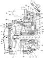
図1は本発明に係るパワーユニット1の側面図である。このパワーユニットはスクータ型自動二輪車の後部に上下揺動可能に搭載されるもので、駆動輪である後輪5の前方に配置される内燃機関2と動力伝達装置3と後輪支持部4と後輪5とを一体化して構成されている。内燃機関は頭上弁式4ストロークサイクル単気筒の水冷式内燃機関である。
FIG. 1 is a side view of a
このパワーユニット1の内燃機関2は、クランクケース6と、シリンダブロック7と、シリンダヘッド8と、シリンダヘッドカバー9とに囲まれた部分よりなり、クランクケース6の前端に略水平方向に指向したシリンダブロック7が結合され、同シリンダブロック7の前端にシリンダヘッド8が結合され、同シリンダヘッド8の前端にシリンダヘッドカバー9が結合されている。
The
図2は図1のII−II断面図である。クランクケース6は左クランクケース6A、右クランクケース6Bとからなっている。左右のクランクケース6A、6Bに保持されたローラベアリング10Aとボールベアリング10Bに、クランク軸11が回転可能に支持されている。一方、シリンダブロック7に形成されたシリンダ穴12にピストン13が摺動可能に嵌装されている。クランク軸11およびピストン13に、それぞれクランクピン14およびピストンピン15を介して、コンロッド16の両端が枢支されている。ピストン13が往復動すると、それに伴ってクランク軸11が回転する。ピストン13の端面に向き合うシリンダヘッド8の底面には燃焼室20が形成され、点火プラグ21が外部から装着され、その先端が上記燃焼室20に臨んでいる。
2 is a cross-sectional view taken along the line II-II in FIG. The
図1において、シリンダヘッド8の上側には上記燃焼室20に連なる吸気ポート22、シリンダヘッド8の下側には燃焼室20に連なる排気ポート23が形成されている。吸気ポート22の燃焼室側開口を開閉する吸気弁24と排気ポート23の燃焼室側開口を開閉する排気弁25が、シリンダヘッド8に摺動可能に嵌挿されている。
In FIG. 1, an
図2において、シリンダヘッド8とシリンダヘッドカバー9の間にクランク軸11と平行にカム軸26が支承され、カム軸26に設けられた吸気用カム27、排気用カム28によって、吸気弁24、排気弁25が開閉駆動される。クランク軸11の右部に設けられた駆動スプロケット30とカム軸26の端に設けられた従動スプロケット31との間に巻き掛けられた無端状チェーン32によって、カム軸26はクランク軸11によって、クランク軸11の1/2の回転数で、回転駆動される。
In FIG. 2, a
右クランクケース6Bの外側に右クランクケースカバー33が設けてあり、その内面に固定されたステータ34と、クランク軸11に固定され上記ステータ34を囲むロータ35とから、発電機36が構成されている。発電機36に隣接して設けてある従動歯車37は図示していないスタータモータからの回転駆動を受けるための歯車である。
A right crankcase cover 33 is provided outside the
パワーユニット1における動力伝達装置3の本体ケース38は、右変速機ケース39、左変速機ケース40および仕切り壁41から構成されている。右変速機ケース39は左クランクケース6Aと一体に製作されている。左変速機ケース40と仕切り壁41は右変速機ケース39に結合されている。動力伝達装置3の本体ケース38自体は後輪支持部4を兼ねている。動力伝達装置3は、Vベルト変速機45と歯車減速機46とからなっている。Vベルト変速機45は、前半部が、左変速機ケース40と右変速機ケース39との間、後半部が、左変速機ケース40と仕切り壁41との間に設けられ、歯車減速機46は、仕切り壁41と右変速機ケース39との間に設けられている。
A
Vベルト変速機45の駆動軸は、クランク軸11そのものであり、同クランク軸11の左端部にVベルト変速機45の駆動プーリ47が設けてある。駆動プーリ47は固定半体48と可動半体49とを備えて構成されている。Vベルト変速機45の従動軸50は、右変速機ケース39と仕切り壁41とに回転自在に支持されており、この従動軸50に遠心クラッチ51を介してVベルト変速機40の従動プーリ52が設けてある。従動プーリ52は固定半体53と可動半体54とを備えて構成されている。駆動プーリ47と従動プーリ52とに無端状Vベルト55が架渡され、駆動プーリ47の回転が従動プーリ52に伝達される。従動プーリ52の回転数が所定回転数を越えると、従動プーリ52と従動軸50との間に設けられている遠心クラッチ51が接続状態となり、従動軸50が回転を始める。
The drive shaft of the V-
歯車減速機46は3本の回転軸に設けられた歯車群によって構成されている。第1の軸は、右変速機ケース39と仕切り壁41とに支持されているVベルト変速機45の従動軸50の右半部であり、小径歯車56が形成されている。第2の軸は、右変速機ケース39と仕切り壁41とに回転自在に支持されている中間軸57であり、上記従動軸50の小径歯車56に噛合う大径歯車58が一体に嵌着されるとともに、それに隣接して小径歯車59が形成されている。第3の軸は、仕切り壁41と右変速機ケース39と内燃機関本体に結合されているアーム62とに回転自在に支持されている後輪軸60であり、上記中間軸57の小径歯車59に噛合う大径歯車61が嵌着されている。この構成によって、従動軸50のトルクは、上記減速歯車群を介して減速されて後輪軸60に伝達される。後輪軸60には、後輪5が一体的に固定されている。
The
図3は駆動プーリ47とその駆動装置の断面展開図である。クランク軸11の左半部に段差11aで区切られた小径部が形成され、そこにボールベアリング63が装着され、更に円筒状スリーブ64と駆動プーリ固定半体48とが、クランク軸端部のスプライン67に嵌合して装着され、クランク軸11端部のねじ11bにワッシャ65を介してナット66が螺着され締められる。これによって、円筒状スリーブ64と駆動プーリ固定半体48はクランク軸11に対して相対回転不可かつ軸線方向相対移動不可に固定される。上記スリーブ64には周方向の1箇所に円弧状のキー溝68が設けられている。
FIG. 3 is a developed sectional view of the driving
駆動プーリ可動半体49は、上記固定半体に対向する傘状のフランジ部49aと上記スリーブ64を囲む円筒状のボス部49bとからなっている。駆動プーリ可動半体49のボス部49bには周方向1箇所に、ボス部49bの半径方向に貫通し、かつ軸線方向に伸びるガイド溝69が設けてあり、そのガイド溝69と上記スリーブ64のキー溝68に係合するトルク伝達キー70が嵌挿されている。これによって、駆動プーリ可動半体49は、スリーブ64に対して、すなわちクランク軸11に対して、相対回転不可であるが、軸線方向には相対移動可能に装着される。
The drive pulley
駆動プーリ可動半体49のボス部49bの外周に、円筒状の支持筒71が、相対回転可能であるが、上記ボス部49bに対して軸線方向相対移動不可に装着されており、これが上記可動半体ボス部49bのガイド溝69の外側開口を覆っている。
A
上記支持筒71の外周にはボールベアリング72の内輪が軸方向相対移動不可に装着され、その外輪は、スライドギヤ73の一端部の内周に軸方向相対移動不可に保持されている。スライドギヤ73は、ボールベアリング72を介して、支持筒71に対して相対回転可能に、したがって駆動プーリ可動半体49に対しても相対回転可能に、軸方向には相対移動不可に結合されている。すなわちスライドギヤ73と可動半体49とは、クランク軸方向には一体的に移動するが、回転方向には別個の動きをする。
An inner ring of a
上記クランク軸に装着されているボールベアリング63の外輪は、クランク軸11を同軸的に囲む円筒状ねじ軸74の内周に軸方向相対移動不可に保持されている。上記スライドギヤ73の他端内周のねじ部73aが上記ねじ軸74の外周のねじ部74aに螺合させてある。上記ねじ軸74には、ねじ軸固定板75が固着されている。ねじ軸固定板75の端部には円筒状の取付け筒76が設けてあり、これを防振ラバー77を介してボルト78で左クランクケース6Aに固定することによって、上記円筒状ねじ軸74は、左クランクケース6Aに対して、クランク軸方向移動不可、回転不可に位置決めされる。上記支持筒71、ボールベアリング72、スライドギヤ73、ねじ軸74、ねじ軸固定板75によって、駆動プーリ可動半体を軸方向に駆動するスライダー機構が構成されている。
The outer ring of the
上記スライドギヤ73は、アクチュエータ80によって回転駆動される。アクチュエータ80は、電動モータ81と歯車減速機構82とによって構成されている。上記電動モータ81は車速とスロットル開度と内燃機関の回転数に応じて自動的に回転が制御されるものである。左クランクケース6Aに減速歯車ケース83が取り付けられ、減速歯車室84が形成されている。取付け板85を介して、電動モータ81が減速歯車ケース83に取付けられ、同モータの回転軸に刻設されたピニオン86が減速歯車室84の中に突入している。
The
上記ピニオン86に噛み合う大径歯車87と、これに隣接する小径歯車88とが一体に構成された第1中間歯車89が左クランクケース6Aと減速歯車ケース83にボールベアリング90を介して回転可能に支持されている。
A first
上記小径歯車88に噛み合う大径歯車91と、これに一体的に隣接する小径歯車92とが、回転軸93に嵌挿されて一体となっている第2中間歯車94が左クランクケース6Aと減速歯車ケース83にボールベアリング95を介して回転可能に支持されている。上記小径歯車92は軸方向寸法が長い歯車で、この軸方向の任意の位置で、上記スライドギヤ73の噛合いが可能となっている。
A second intermediate gear 94 in which a large-
上記第2中間歯車94の回転軸93の端部に歯車93aが設けてあり、減速歯車ケース83に回転可能に設けられたストロークセンサ軸96の周囲部に設けられたウオーム96aと噛み合っている。ストロークセンサ105(図1参照)は駆動プーリ可動半体49のストロークを検出するものである。
A
ねじ軸はボルト78によって左クランクケースに固定されている。電動モータが始動していない時は、スライドギヤ73は静止している。内燃機関が運転されると、駆動プーリ固定半体48、駆動プーリ可動半体49、スリーブ64、トルク伝達キー70、支持筒71はクランク軸11とともに回転するが、ボールベアリング63、72の介在によって、ねじ軸74とスライドギヤ73は、クランク軸11の回転の影響を受けない。
The screw shaft is fixed to the left crankcase by a
電動モータ81が制御指令に応じて正方向に回転すると、第1、第2中間歯車89、94を経由して動力が伝達され、スライドギヤ73が回転し、ねじ軸74のねじ部74aに噛み合っているスライドギヤ73のねじ部73aの回転によって、スライドギヤ73自体がクランク軸11の軸方向へ移動し、ボールベアリング72と支持筒71を介して駆動プーリ可動半体49を押し、駆動プーリ固定半体48との間隔を狭め、Vベルトをトップ位置Tの方へ移動させる。電動モータ81が制御指令に応じて逆方向に回転すると、上記とは逆の過程によって、駆動プーリ固定半体48と駆動プーリ可動半体49との間隔が広がり、Vベルトはロー位置Lの方へ移動する。なお、スライドギヤ73のロー側ストッパ75aはねじ軸固定板75の他端に設けてあり、スライドギヤ73のトップ側ストッパ97は左クランクケース6Aにボルト98で固定してある。
When the
図4は、トルク伝達キーに関する騒音発生のメカニズムの説明図である。図はピストン13が上死点にある状態を示している。ピストン13が上死点にある時には、燃料の燃焼による燃焼室の急激な圧力上昇によって、ピストン13の頂面に大きな力Fが加わる。この力はコンロッド16、クランクピン14を介してクランク軸11の中心部を下方へ押す。クランク軸11の中心部はごく僅かであるが撓み変形を起こす。これによってクランク軸11の両端部には、ベアリング10A、10Bを支点とする跳ね上げモーメントMが生じ、クランク軸の両端部は僅かであるが上方へ変位する。もし駆動プーリ可動半体49のトルク伝達キー70が1個であり、クランク軸軸線C−Cに関してクランクピン14と同じ側に設けてあるとすれば、クランク軸11の上記跳ね上げモーメントMによる変位によって、トルク伝達キー70はクランク軸半径方向外方へ向けてスリーブ64のキー溝68の底面から伝達される反力Rによって突き上げられる。支持筒71の内面とトルク伝達キー70の外側面との間には、支持筒71と可動半体49のクランク軸軸方向摺動を可能とするために若干のクリアランスがあるので、反力Rによって突き上げられたトルク伝達キー70は支持筒71内面に当接して打音を発生する。したがって、トルク伝達キー70を、反力Rが加わらない側、即ちクランク軸軸線C−Cに関して、クランクピン14と反対側に設けるなら、打音の発生を低減することができる。
FIG. 4 is an explanatory diagram of a noise generation mechanism related to the torque transmission key. The figure shows a state where the
図5は本発明の実施形態のクランク軸11の左半部の断面図である。図において、駆動プーリ固定半体48は全体がアルミ合金製である。駆動プーリ可動半体49は、傘状のフランジ部49aがアルミ合金製、中心のボス部49bがスチール製である。これは、あらかじめ製作されているボス部49bの端にフランジ部49aが鋳造によって一体的に形成されたものである。スリーブ64、トルク伝達キー70、および支持筒71はスチール製である。本実施形態では、前述のように、騒音発生を低減することのできる一つの場合を実現するために、クランクピン14とトルク伝達キー70とはクランク軸11の軸線C−Cを挟んで反対側に設置される。
FIG. 5 is a cross-sectional view of the left half of the
図6は、図5のVI−VI断面図にクランクピン14の位置を示した図である。図6において矢印Pはクランク軸軸線Cに対するクランクピン14の方向を示している。またクランク軸軸線Cから放射状に伸びている線は、上記クランクピン方向Pを0度とし、クランク軸軸線Cを中心として、クランク軸回転方向Wに測った角度を示している。上記実施形態のキー溝68とガイド溝69とトルク伝達キー70は、クランク軸軸線Cに関して180度の位置に設けてある。即ち、駆動プーリ可動半体のボス部49b、スリーブ64、支持筒71、およびトルク伝達キー70は、トルク伝達キー70がクランク軸11の軸線Cに関してクランクピン14とは反対の側に位置するように装着されている。
6 is a view showing the position of the
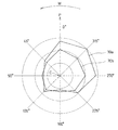
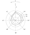
図7、図8はクランク軸周囲に於けるトルク伝達キー70の組付け位置に関する実験結果を示すレーダーチャートであって、矢印Pはクランク軸軸線Cに対するクランクピン14の方向を示し、クランク軸軸線Cから放射状に伸びている線は、上記クランクピンの方向Pを0度とし、クランク軸回転方向Wに測った角度を示している。図7は、クランク軸軸線Cに関する各方向のキー組付け位置に対する打音の高さ、即ち近接音圧(dB)の測定値を図示したものであって、測定結果の折れ線が図の中心Cから離れている程、打音が高く、図の中心Cに近い程打音が低いことを示している。また、図8は、各方向のトルク伝達キー組付け位置に対する音質を、観測者の聴覚によって評価した結果を図示したもので、折れ線が図の中心Cから離れている程、不快な音であり、図の中心Cに近い程、不快の程度が低い音であることを示している。実験結果の折れ線が各図に2本描いてある。これは図9に示す2種類のキー70a、70bに対応する折れ線を示している。
FIG. 7 and FIG. 8 are radar charts showing experimental results regarding the assembly position of the
図9は、上記実験に用いた2種類のトルク伝達キー70の斜視図である。図(a)には、支持筒71の内面に当接するトルク伝達キー70の頂面が平面状のフラットキー70a、図(b)には、頂面がクランク軸軸線方向の母線を有する湾曲面で形成されたラウンドキー70bを示してある。フラットキー70aは、2本の側縁e、eによって支持筒71の内面に当接し、ラウンドキー70bは1本の母線gによって支持筒71の内面に当接する。
FIG. 9 is a perspective view of two types of
上記図7、図8において、トルク伝達キー70の設置位置が315度、即ち、−45度、の前後において騒音が大きくなっている。これは、ピストンが上死点を過ぎ、クランク軸が上死点位置から若干回転した時に、燃焼室圧力が最大となるため、トルク伝達キー設置位置が−45度の付近となっている場合に、騒音が大となるものと推測される。
In FIGS. 7 and 8, the noise is large before and after the installation position of the
図6には、トルク伝達キー70をクランク軸軸線Cに関してクランクピン方向Pからクランク軸回転方向Wに測って180度の位置とした例が示してあるが、図7〜図9から、クランク軸軸線Cを中心とし、クランクピン方向Pから、クランク軸の回転方向Wに測って90度〜225度の範囲、即ち図示の範囲Eの中に入るようにトルク伝達キー70を組み付ければ、他の方向に比して騒音を低減しうることがわかる。また、フラットキー70aとラウンドキー70bとでは、ラウンドキー70bの方が騒音が低いことがわかる。
FIG. 6 shows an example in which the
図10は、駆動プーリ可動半体49等をクランク軸11に組付ける手順の説明図である。駆動プーリ可動半体49等をクランク軸11に組付ける場合には、組付けの前に、予め、図10のクランク軸11とクランクピン14を除く部分全部を、可動半体組立て体79として一体的に組み立てておき、その組立て体79をクランク軸11の端部から装着する。可動半体組立て体79として一体のものとして組み立てる部材は、スリーブ64、駆動プーリ可動半体49、トルク伝達キー70、支持筒71、ボールベアリング72、スライドギヤ73、ねじ軸74、ねじ軸固定板75、ボールベアリング63、およびボールベアリング抜け止めリング、シール部材などである。この組立て体79をクランク軸11に装着する際の、クランクピン14に対するトルク伝達キー70の位相は、クランク軸11側のスプライン67とスリーブ64の端部のスプライン64aとの周方向噛み合わせ位置に応じて決まる。クランク軸11への組付けに際しては、上記トルク伝達キー70の周方向位置が、所望の位置となるように組付けねばならない。
FIG. 10 is an explanatory diagram of the procedure for assembling the drive pulley
図11は、可動半体組立て体79をクランク軸11に組付ける手順を示す図であって、組付けた後の状態をクランク軸11の軸端側から見た図である。図には部分的に、図10のH−H断面、K−K断面が描いてある。この組付け手順説明図では、トルク伝達キー70はクランクピン方向Pから測って180度の位置に設置する例を示してある。クランク軸11の端面に、クランク軸軸線Cに対してクランクピン14側にポンチマーク99が付してある。一方、クランク軸軸線Cを挟んでトルク伝達キー70の反対側の可動半体49の前面に、不滅インクマーク100が付してある。クランク軸11への可動半体組立て体79のクランク軸11への装着に際しては、上記ポンチマーク99と不滅インクマーク100とが、クランク軸軸線Cに対して同一方向となるように組立て体79を装着すれば、クランク軸軸線Cを挟んでクランクピン14の反対側にトルク伝達キー70を位置させることができる。なお、不滅インクは容易に消えないインクのことであるが、不滅インクの代わりにラッカー、ペイント等を用いてもよい。
FIG. 11 is a diagram showing a procedure for assembling the movable half-
上記実施例は、可動半体の中心に近い場所に不滅インクマーク100を施した例を示した。このマークの場所は、可動半体組立て体79の前面のクランク軸軸線Cを挟んでトルク伝達キー70の反対側の線上であればどこでもよく、たとえばスリーブ64の端面に付したマーク100x、あるいは可動半体フランジ部の外周上に付したマーク100yであってもよい。
The above embodiment has shown an example in which the
図12は、可動半体組立て体79をクランク軸11に組付ける手順の他の例を示す図であって、組付けた後の状態をクランク軸11の軸端側から見た図である。この例は、トルク伝達キー70を、クランクピン方向Pからクランク軸回転方向Wへ測って135度の方向に設けようとする場合の例である。ポンチマーク99はクランク軸11の端面のクランクピン方向Pに設けるものとしている。この時、不滅インクマーク100、100x、100y等は、トルク伝達キー70の方向からクランク軸回転方向Wの逆方向へ向けて135度の方向に付ける。クランク軸11に可動半体組立て体79を装着する際には、上記ポンチマーク99と不滅インクマーク100等が、クランク軸軸線Cに対して同一方向となるように組立て体79を装着すれば、トルク伝達キー70を所望の135度の位置に設置することができる。
FIG. 12 is a view showing another example of the procedure for assembling the movable half-
一般に、ポンチマーク99をクランクピン方向Pに設けるものとすれば、トルク伝達キー70を、クランクピン方向Pからクランク軸回転方向Wへ測ってθ度の方向に設けようとする場合には、不滅インクマーク100は、トルク伝達キー70の位置からクランク軸の回転方向Wの逆方向へ測ってθ度の方向に付ける。可動半体組立て体79をクランク軸11に装着する際には、ポンチマーク99と不滅インクマーク100とが同じ方向となるようにして、スプライン67、64aを噛み合わせればよいことになる。
In general, if the
なお、可動半体49の外縁部に不滅インクマーク100yを設ける場合には、不滅インクマーク100yとクランクピン14を両方とも同時に視野に入れることができるので、ポンチマーク99を省略し、不滅インクマーク100yの方向を直接クランクピン14の方向と一致するようにして、スプライン67、64aを噛み合わせることもできる。
When the
上記実施形態では半月形のトルク伝達キーを用いた例を示したが、本発明は、他の形状のキーに対しても適用できる。またトルク伝達用のピンを用いてあっても適用できる。 In the above embodiment, an example using a half-moon-shaped torque transmission key is shown, but the present invention can be applied to keys having other shapes. Further, the present invention can be applied even if a torque transmitting pin is used.
以上詳述したように、本発明の実施形態においては、下記の効果がもたらされる。
(1)トルク伝達キー70を、クランク軸軸線Cを中心とし、クランクピン方向Pから、クランク軸回転方向Wに測って、90度から225度までの範囲(図6の範囲E)に設けることによって、歪みとクランク軸の振れ回り振動に基づくトルク伝達キー70と支持筒71との間の騒音を低減させることができる。
(2)スライド機構に対するガイド部材をクランク軸周方向に1個だけ設けるようにしたので、キーを複数個設ける場合に必要となる相互誤差吸収のために必要とされていた周方向クリアランスの確保が不要となり、周方向のがたを少なくすることができる。したがって、径方向の騒音低減と相俟って周方向の当接によって生じる騒音も低減することができる。
(3)支持筒への当接面を曲面としたトルク伝達キーを用いると、支持筒への当接部が1本の母線だけになるので、一層騒音を低減することができる。
(4)クランク軸部を比較的小型に維持したままで騒音低減が可能であるため、スライダー機構をクランク軸の周囲に配置することができ、Vベルト式自動変速機の構造を小型化することができる。
(5)ポンチマークと不滅インクマークの利用によって、現場における駆動プーリ可動半体の組付け作業に際して、トルク伝達キーを設計上の適切な位置に、間違いなく設置することができる。
As described in detail above, the following effects are brought about in the embodiment of the present invention.
(1) The
(2) Since only one guide member for the slide mechanism is provided in the circumferential direction of the crankshaft, it is possible to secure the circumferential clearance required for absorbing mutual errors required when a plurality of keys are provided. It becomes unnecessary, and play in the circumferential direction can be reduced. Therefore, coupled with the reduction of the noise in the radial direction, it is possible to reduce the noise generated by the circumferential contact.
(3) When a torque transmission key having a curved contact surface with the support tube is used, the contact portion with the support tube is only one bus bar, so that noise can be further reduced.
(4) Since the noise can be reduced while keeping the crankshaft part relatively small, the slider mechanism can be arranged around the crankshaft, and the structure of the V-belt type automatic transmission can be miniaturized. Can do.
(5) By using the punch mark and the immortal ink mark, the torque transmission key can be definitely installed at an appropriate position in the design when the drive pulley movable half is assembled in the field.
45…Vベルト変速機、47…駆動プーリ、48…駆動プーリ固定半体、49…駆動プーリ可動半体、49a…フランジ部、49b…ボス部、64…スリーブ、64a…スリーブ端のスプライン、67…スプライン、68…キー溝、69…ガイド溝、70…トルク伝達キー、70a…フラットキー、70b…ラウンドキー、71…支持筒、73…スライドギヤ、74…ねじ軸、75…ねじ軸固定板、79…可動半体組立て体、80…アクチュエータ、81…電動モータ、82…歯車減速機構、99…ポンチマーク、100…不滅インクマーク。
45 ... V belt transmission, 47 ... Driving pulley, 48 ... Driving pulley fixed half, 49 ... Driving pulley movable half, 49a ... Flange portion, 49b ... Boss portion, 64 ... Sleeve, 64a ... Sleeve end spline, 67 ... Spline, 68 ... Key groove, 69 ... Guide groove, 70 ... Torque transmission key, 70a ... Flat key, 70b ... Round key, 71 ... Support cylinder, 73 ... Slide gear, 74 ... Screw shaft, 75 ... Screw shaft fixing plate , 79 ... movable half assembly, 80 ... actuator, 81 ... electric motor, 82 ... gear reduction mechanism, 99 ... punch mark, 100 ... immortal ink mark.
Claims (5)
上記可動半体(49)は、Vベルト(55)を保持する傘状のフランジ部(49a)と筒状のボス部(49b)とからなり、該ボス部(49b)にクランク軸(11)からの駆動トルクが伝達されるガイド溝(69)を備え、
上記ボス部(49b)のガイド溝(69)と、クランク軸(11)側に形成されたキー溝(68)とに、クランク軸(11)の駆動トルクを可動半体(49)に伝達するトルク伝達キー(70)が嵌合保持され、
上記トルク伝達キー(70)は、クランク軸軸線(C)を中心として、上記クランクピン(14)と位相が反対の側に設けられたことを特徴とするVベルト式自動変速機。 A crankshaft (11) having a crankpin (14) is rotatably supported between a pair of bearings (10A, 10B) held in the crankcase (6), and the crankshaft (11) is outside the bearing. the one end, fixed half fixed on the crank shaft (11) and (48), slidable in the crankshaft direction on the crank shaft (11) opposite to the fixed half (48) In a V-belt type automatic transmission having a drive pulley (47) composed of a movable half body (49) ,
The movable half (49) includes an umbrella-shaped flange (49a ) for holding the V-belt (55) and a cylindrical boss (49b). The boss (49b) has a crankshaft (11). A guide groove (69) through which drive torque is transmitted,
The driving torque of the crankshaft (11 ) is transmitted to the movable half (49) through the guide groove (69 ) of the boss portion (49b) and the keyway (68) formed on the crankshaft (11) side. The torque transmission key (70) is fitted and held,
The V-belt type automatic transmission, wherein the torque transmission key (70) is provided on the opposite side of the crankpin (14) with the crankshaft axis (C) as a center .
上記可動半体(49)は、Vベルト(55)を保持する傘状のフランジ部(49a)と筒状のボス部(49b)とからなり、該ボス部(49b)にクランク軸(11)からの駆動トルクが伝達されるガイド溝(69)を備え、
上記ボス部(49b)のガイド溝(69)と、クランク軸(11)側に形成されたキー溝(68)とに、クランク軸(11)の駆動トルクを可動半体(49)に伝達するトルク伝達キー(70)が嵌合保持され、
上記トルク伝達キー(70)は、クランク軸軸線(C)を中心とし、クランクピン方向(P)から、クランク軸回転方向(W)に測って、90度から225度の範囲に設けられたことを特徴とするVベルト式自動変速機。 A crankshaft (11) having a crankpin (14) is rotatably supported between a pair of bearings (10A, 10B) held in the crankcase (6), and the crankshaft (11) is outside the bearing. the one end, fixed half fixed on the crank shaft (11) and (48), slidable in the crankshaft direction on the crank shaft (11) opposite to the fixed half (48) In a V-belt type automatic transmission having a drive pulley (47) composed of a movable half body (49) ,
The movable half (49) includes an umbrella-shaped flange (49a ) for holding the V-belt (55) and a cylindrical boss (49b). The boss (49b) has a crankshaft (11). A guide groove (69) through which drive torque is transmitted,
The driving torque of the crankshaft (11 ) is transmitted to the movable half (49) through the guide groove (69 ) of the boss portion (49b) and the keyway (68) formed on the crankshaft (11) side. The torque transmission key (70) is fitted and held,
The torque transmission key (70) is provided in the range of 90 to 225 degrees with the crankshaft axis (C) as the center and measured from the crankpin direction (P) to the crankshaft rotation direction (W). V-belt type automatic transmission characterized by this.
Priority Applications (7)
| Application Number | Priority Date | Filing Date | Title |
|---|---|---|---|
| JP2004307807A JP4588412B2 (en) | 2004-10-22 | 2004-10-22 | V-belt type automatic transmission |
| TW094134974A TW200630554A (en) | 2004-10-22 | 2005-10-06 | V-belt type automatic transmission |
| ES07110237T ES2312157T3 (en) | 2004-10-22 | 2005-10-10 | AUTOMATIC TRANSMISSION OF THE V-BELT TYPE. |
| EP07110237A EP1826113B1 (en) | 2004-10-22 | 2005-10-10 | V-belt type automatic transmission |
| EP20050022030 EP1650475B1 (en) | 2004-10-22 | 2005-10-10 | V-belt type automatic transmission |
| ES05022030T ES2293457T3 (en) | 2004-10-22 | 2005-10-10 | AN AUTOMATIC TRANSMISSION OF THE V-BELT TYPE. |
| CNB2005101141027A CN100429429C (en) | 2004-10-22 | 2005-10-20 | V-belt type automatic transmission |
Applications Claiming Priority (1)
| Application Number | Priority Date | Filing Date | Title |
|---|---|---|---|
| JP2004307807A JP4588412B2 (en) | 2004-10-22 | 2004-10-22 | V-belt type automatic transmission |
Related Child Applications (1)
| Application Number | Title | Priority Date | Filing Date |
|---|---|---|---|
| JP2007159652A Division JP4481322B2 (en) | 2007-06-18 | 2007-06-18 | V-belt type automatic transmission |
Publications (2)
| Publication Number | Publication Date |
|---|---|
| JP2006118630A JP2006118630A (en) | 2006-05-11 |
| JP4588412B2 true JP4588412B2 (en) | 2010-12-01 |
Family
ID=35432623
Family Applications (1)
| Application Number | Title | Priority Date | Filing Date |
|---|---|---|---|
| JP2004307807A Expired - Fee Related JP4588412B2 (en) | 2004-10-22 | 2004-10-22 | V-belt type automatic transmission |
Country Status (5)
| Country | Link |
|---|---|
| EP (2) | EP1826113B1 (en) |
| JP (1) | JP4588412B2 (en) |
| CN (1) | CN100429429C (en) |
| ES (2) | ES2312157T3 (en) |
| TW (1) | TW200630554A (en) |
Families Citing this family (5)
| Publication number | Priority date | Publication date | Assignee | Title |
|---|---|---|---|---|
| JP4849554B2 (en) * | 2007-01-29 | 2012-01-11 | ヤマハ発動機株式会社 | Engine unit and saddle riding type vehicle equipped with the same |
| JP2008196562A (en) | 2007-02-09 | 2008-08-28 | Yamaha Motor Co Ltd | Power unit and straddle-type vehicle |
| JP2008215506A (en) * | 2007-03-05 | 2008-09-18 | Yamaha Motor Co Ltd | Continuously variable transmission and saddle-riding type vehicle provided therewith |
| US20090280936A1 (en) * | 2008-05-08 | 2009-11-12 | Andy Blaine Appleton | Variable belt drive |
| JPWO2014115384A1 (en) * | 2013-01-28 | 2017-01-26 | トヨタ自動車株式会社 | Belt type continuously variable transmission |
Citations (3)
| Publication number | Priority date | Publication date | Assignee | Title |
|---|---|---|---|---|
| JPH112316A (en) * | 1997-06-13 | 1999-01-06 | Yamaha Motor Co Ltd | Negative pressure speed change control device for vehicle |
| WO2004044457A1 (en) * | 2002-11-11 | 2004-05-27 | Yamaha Hatsudoki Kabushiki Kaisha | V-belt type variable speed drive |
| JP2004251391A (en) * | 2003-02-20 | 2004-09-09 | Yamaha Motor Co Ltd | V-belt type continuously variable transmission for engine |
Family Cites Families (17)
| Publication number | Priority date | Publication date | Assignee | Title |
|---|---|---|---|---|
| US3948112A (en) * | 1976-01-23 | 1976-04-06 | Gilbert Robert B | Output speed-controlled transmission |
| JPS55155951A (en) * | 1979-05-23 | 1980-12-04 | Honda Motor Co Ltd | Power transmission in motorcycle |
| JPS59170552A (en) * | 1983-03-17 | 1984-09-26 | Honda Motor Co Ltd | V-belt transmission type automatic transmission |
| JPS63190962A (en) * | 1987-02-03 | 1988-08-08 | Suzuki Motor Co Ltd | Driven v-pulley for v-belt automatic transmission |
| JP2697828B2 (en) * | 1987-08-28 | 1998-01-14 | 株式会社日立製作所 | Automatic transmission for vehicles |
| JP2967374B2 (en) * | 1990-11-20 | 1999-10-25 | 本田技研工業株式会社 | Continuously variable transmission for vehicles |
| JP3043061B2 (en) * | 1990-11-30 | 2000-05-22 | ヤマハ発動機株式会社 | V-belt type automatic transmission for motorcycles |
| JPH04121566U (en) * | 1991-04-22 | 1992-10-30 | 栃木富士産業株式会社 | variable speed pulley |
| JP2600500Y2 (en) * | 1992-06-15 | 1999-10-12 | 本田技研工業株式会社 | Guide member for movable pulley |
| JPH08178004A (en) * | 1994-12-27 | 1996-07-12 | Suzuki Motor Corp | V-belt type automatic transmission |
| JP3201988B2 (en) * | 1997-12-11 | 2001-08-27 | 川崎重工業株式会社 | Power transmission mechanism |
| JPH11257447A (en) * | 1998-03-10 | 1999-09-21 | Suzuki Motor Corp | V-belt type automatic transmission |
| JP2001248697A (en) * | 2000-03-02 | 2001-09-14 | Suzuki Motor Corp | V-belt type automatic transmission |
| ITTO20010259A1 (en) * | 2000-03-30 | 2002-09-19 | Honda Motor Co Ltd | POWER TRANSMISSION SYSTEM FOR SMALL VEHICLES. |
| JP2002206604A (en) * | 2001-01-12 | 2002-07-26 | Yamaha Motor Co Ltd | V-belt type automatic transmission |
| JP4281290B2 (en) * | 2002-04-17 | 2009-06-17 | スズキ株式会社 | Cooling structure for belt-type transmission |
| JP4293796B2 (en) * | 2003-01-31 | 2009-07-08 | ヤマハ発動機株式会社 | Cooling structure for V-belt type continuously variable transmission |
-
2004
- 2004-10-22 JP JP2004307807A patent/JP4588412B2/en not_active Expired - Fee Related
-
2005
- 2005-10-06 TW TW094134974A patent/TW200630554A/en not_active IP Right Cessation
- 2005-10-10 EP EP07110237A patent/EP1826113B1/en not_active Expired - Fee Related
- 2005-10-10 EP EP20050022030 patent/EP1650475B1/en not_active Expired - Fee Related
- 2005-10-10 ES ES07110237T patent/ES2312157T3/en active Active
- 2005-10-10 ES ES05022030T patent/ES2293457T3/en active Active
- 2005-10-20 CN CNB2005101141027A patent/CN100429429C/en not_active Expired - Fee Related
Patent Citations (3)
| Publication number | Priority date | Publication date | Assignee | Title |
|---|---|---|---|---|
| JPH112316A (en) * | 1997-06-13 | 1999-01-06 | Yamaha Motor Co Ltd | Negative pressure speed change control device for vehicle |
| WO2004044457A1 (en) * | 2002-11-11 | 2004-05-27 | Yamaha Hatsudoki Kabushiki Kaisha | V-belt type variable speed drive |
| JP2004251391A (en) * | 2003-02-20 | 2004-09-09 | Yamaha Motor Co Ltd | V-belt type continuously variable transmission for engine |
Also Published As
| Publication number | Publication date |
|---|---|
| JP2006118630A (en) | 2006-05-11 |
| TWI296687B (en) | 2008-05-11 |
| TW200630554A (en) | 2006-09-01 |
| CN100429429C (en) | 2008-10-29 |
| EP1826113B1 (en) | 2008-09-03 |
| EP1650475A1 (en) | 2006-04-26 |
| CN1763398A (en) | 2006-04-26 |
| ES2312157T3 (en) | 2009-02-16 |
| EP1826113A1 (en) | 2007-08-29 |
| ES2293457T3 (en) | 2008-03-16 |
| EP1650475B1 (en) | 2007-09-05 |
Similar Documents
| Publication | Publication Date | Title |
|---|---|---|
| JP4573720B2 (en) | V belt type continuously variable transmission | |
| JPH04366064A (en) | Continuously variable transmission for vehicle | |
| EP1650475B1 (en) | V-belt type automatic transmission | |
| US7201263B2 (en) | Viscous damper | |
| JP4481322B2 (en) | V-belt type automatic transmission | |
| EP1666721B1 (en) | Internal combustion engine | |
| JP4825324B2 (en) | Drive device | |
| US7162989B2 (en) | Engine unit of motorcycle | |
| JP4776213B2 (en) | V-belt type automatic transmission | |
| JP2007232221A5 (en) | ||
| CN108603574B (en) | Engine unit | |
| EP1630455A2 (en) | Transmission gear with variable pulley | |
| KR100871405B1 (en) | V-belt type continuously variable transmission | |
| JP6594791B2 (en) | Electronically controlled V-belt type continuously variable transmission | |
| JP2004278634A (en) | Beat sound preventing structure in crankshaft support bearing for motorcycle | |
| EP1130236B1 (en) | Engine | |
| JP4698339B2 (en) | V belt type continuously variable transmission | |
| JP4519890B2 (en) | V belt type continuously variable transmission | |
| JP2006312918A (en) | Power unit for engine | |
| JP2018003741A (en) | Variable valve mechanism, engine, and motor cycle | |
| JP2006307654A (en) | Magneto mounting structure of engine | |
| JP2007278158A (en) | Engine start device | |
| JP2017150544A5 (en) | ||
| JPH109354A (en) | Variable diameter pulley device of continuously variable transmission with v-belt | |
| JPH08303222A (en) | Valve system for engine |
Legal Events
| Date | Code | Title | Description |
|---|---|---|---|
| A621 | Written request for application examination |
Free format text: JAPANESE INTERMEDIATE CODE: A621 Effective date: 20061129 |
|
| RD04 | Notification of resignation of power of attorney |
Free format text: JAPANESE INTERMEDIATE CODE: A7424 Effective date: 20090501 |
|
| A977 | Report on retrieval |
Free format text: JAPANESE INTERMEDIATE CODE: A971007 Effective date: 20091112 |
|
| A131 | Notification of reasons for refusal |
Free format text: JAPANESE INTERMEDIATE CODE: A131 Effective date: 20091124 |
|
| A521 | Request for written amendment filed |
Free format text: JAPANESE INTERMEDIATE CODE: A523 Effective date: 20100119 |
|
| A131 | Notification of reasons for refusal |
Free format text: JAPANESE INTERMEDIATE CODE: A131 Effective date: 20100216 |
|
| A521 | Request for written amendment filed |
Free format text: JAPANESE INTERMEDIATE CODE: A523 Effective date: 20100407 |
|
| TRDD | Decision of grant or rejection written | ||
| A01 | Written decision to grant a patent or to grant a registration (utility model) |
Free format text: JAPANESE INTERMEDIATE CODE: A01 Effective date: 20100907 |
|
| A01 | Written decision to grant a patent or to grant a registration (utility model) |
Free format text: JAPANESE INTERMEDIATE CODE: A01 |
|
| A61 | First payment of annual fees (during grant procedure) |
Free format text: JAPANESE INTERMEDIATE CODE: A61 Effective date: 20100908 |
|
| R150 | Certificate of patent or registration of utility model |
Ref document number: 4588412 Country of ref document: JP Free format text: JAPANESE INTERMEDIATE CODE: R150 Free format text: JAPANESE INTERMEDIATE CODE: R150 |
|
| FPAY | Renewal fee payment (event date is renewal date of database) |
Free format text: PAYMENT UNTIL: 20130917 Year of fee payment: 3 |
|
| FPAY | Renewal fee payment (event date is renewal date of database) |
Free format text: PAYMENT UNTIL: 20140917 Year of fee payment: 4 |
|
| R250 | Receipt of annual fees |
Free format text: JAPANESE INTERMEDIATE CODE: R250 |
|
| LAPS | Cancellation because of no payment of annual fees |