JP2005291473A - Clutch lubrication equipment - Google Patents
Clutch lubrication equipment Download PDFInfo
- Publication number
- JP2005291473A JP2005291473A JP2004111328A JP2004111328A JP2005291473A JP 2005291473 A JP2005291473 A JP 2005291473A JP 2004111328 A JP2004111328 A JP 2004111328A JP 2004111328 A JP2004111328 A JP 2004111328A JP 2005291473 A JP2005291473 A JP 2005291473A
- Authority
- JP
- Japan
- Prior art keywords
- clutch
- shaft
- crankshaft
- input shaft
- driven
- Prior art date
- Legal status (The legal status is an assumption and is not a legal conclusion. Google has not performed a legal analysis and makes no representation as to the accuracy of the status listed.)
- Pending
Links
Images
Classifications
-
- F—MECHANICAL ENGINEERING; LIGHTING; HEATING; WEAPONS; BLASTING
- F16—ENGINEERING ELEMENTS AND UNITS; GENERAL MEASURES FOR PRODUCING AND MAINTAINING EFFECTIVE FUNCTIONING OF MACHINES OR INSTALLATIONS; THERMAL INSULATION IN GENERAL
- F16H—GEARING
- F16H57/00—General details of gearing
- F16H57/04—Features relating to lubrication or cooling or heating
- F16H57/0434—Features relating to lubrication or cooling or heating relating to lubrication supply, e.g. pumps; Pressure control
Landscapes
- Engineering & Computer Science (AREA)
- General Engineering & Computer Science (AREA)
- Mechanical Engineering (AREA)
- General Details Of Gearings (AREA)
- One-Way And Automatic Clutches, And Combinations Of Different Clutches (AREA)
- Transmissions By Endless Flexible Members (AREA)
Abstract
Description
本発明はクラッチ入力軸とこれに同軸状に配置される被駆動軸との間に設けられる遠心クラッチに潤滑油を供給するクラッチの潤滑装置に関する。 The present invention relates to a clutch lubrication device for supplying lubricating oil to a centrifugal clutch provided between a clutch input shaft and a driven shaft disposed coaxially thereto.
バギー車とも言われる不整地走行車ないし全地形走行車つまりATVは、四輪の一人乗り用のオフロード車であり、ハンティングやトレールツーリングなどのレジャー用のほか一部では農業用実用車としても利用されている。このような全地形走行車のエンジン動力を駆動輪に伝達するための動力伝達装置は、エンジンにより駆動されるクランク軸と、クランク軸の回転が遠心クラッチを介して入力されるベルト式の無段変速機とを有している。ベルト式の無段変速機は変速機入力軸側のプライマリ軸と、これに平行となった出力軸側のセカンダリ軸とを有しており、クランク軸をプライマリ軸と同軸状に配置すると、動力伝達装置は2軸構成となる。これに対し、クランク軸に平行に副軸を配置してこれら両軸を歯車列を介して連結してクランク軸により副軸を駆動するようにし、この副軸にプライマリ軸を同軸状に配置するようにすると、動力伝達装置はプライマリ軸とセカンダリ軸とにクランク軸が相互に平行となって配置される3軸構成となり、車幅方向の動力伝達装置の寸法が短くなる。 Roughly terrain vehicles or all-terrain vehicles, or ATVs, also known as buggy vehicles, are four-wheeled single-seater off-road vehicles that can be used for leisure purposes such as hunting and trail touring, and in some cases as agricultural utility vehicles. It's being used. Such a power transmission device for transmitting engine power of an all-terrain vehicle to a drive wheel includes a crankshaft driven by the engine, and a belt-type continuously variable input of rotation of the crankshaft via a centrifugal clutch. And a transmission. A belt-type continuously variable transmission has a primary shaft on the transmission input shaft side and a secondary shaft on the output shaft side parallel to the primary shaft. When the crankshaft is arranged coaxially with the primary shaft, The transmission device has a two-axis configuration. On the other hand, the auxiliary shaft is arranged in parallel to the crankshaft, these two shafts are connected via a gear train, and the auxiliary shaft is driven by the crankshaft, and the primary shaft is coaxially arranged on the auxiliary shaft. If it does in this way, a power transmission device will become a 3 axis | shaft structure by which a crankshaft is arrange | positioned in parallel with a primary shaft and a secondary shaft, and the dimension of the power transmission device of a vehicle width direction becomes short.
2軸構成のATVの動力伝達装置は、特許文献1に記載されるように、クランク軸とこれと同軸状のプライマリ軸との間に遠心クラッチと一方向クラッチとが装着される構造となる。遠心クラッチはクラッチ入力軸としてのクランク軸の回転が所定の回転数以上になったときに、クランク軸の回転を被駆動軸としてのプライマリ軸に伝達するために使用される。一方向クラッチはクランク軸の回転数がプライマリ軸の回転数よりも高いときにはクランク軸とプライマリ軸とを接続させることなく開放状態とし、車両の減速時などのようにプライマリ軸の回転数がクランク軸の回転数よりも高くなるときにはプライマリ軸をクランク軸に接続させてエンジンブレーキを働かせるために使用される。 As described in Patent Document 1, a two-shaft ATV power transmission device has a structure in which a centrifugal clutch and a one-way clutch are mounted between a crankshaft and a coaxial primary shaft. The centrifugal clutch is used to transmit the rotation of the crankshaft to the primary shaft as the driven shaft when the rotation of the crankshaft as the clutch input shaft exceeds a predetermined rotational speed. The one-way clutch is opened without connecting the crankshaft and primary shaft when the crankshaft rotation speed is higher than the primary shaft rotation speed, and the primary shaft rotation speed is set to the crankshaft when the vehicle is decelerating. It is used to connect the primary shaft to the crankshaft to activate the engine brake when the engine speed becomes higher.
一方、3軸構成の動力伝達装置においては、副軸をクラッチ入力軸としプライマリ軸を被駆動軸としてこれらの間に遠心クラッチが装着されることになり、3軸構成の動力伝達装置においては、副軸とプライマリ軸との間に遠心クラッチと一方向クラッチとが装着される構造となる。
上述したATVの動力伝達装置には、この装置を構成する部材に対して潤滑油を供給するためにエンジン側のケースにオイルポンプが組み込まれており、ケースに形成された油路、クランク軸の軸心に穿設された油路、および遠心クラッチの入力側のボスに形成された油路を介してオイルポンプからの潤滑油を、一方向クラッチに供給した後に遠心クラッチに供給するようにしている。エンジンにより駆動されるオイルポンプはケースのような固定側部材に組み込まれているので、遠心クラッチに供給される油量は、エンジン回転数が低いときには少なく、エンジン回転数の上昇に伴って増加する。したがって、アイドリング時などのようにエンジン低回転域であって遠心クラッチが開放された状態のときには潤滑油が必要となるが、そのときには潤滑油の供給量が低下し、走行中などのようにエンジン回転数の上昇によって遠心クラッチが接続されたときには、遠心クラッチに潤滑油を供給する必要がない状態にも拘わらず、逆に遠心クラッチに供給される潤滑油が増加してしまうという不都合がある。潤滑油を供給する必要がないときに、高回転のエンジンでオイルポンプから多量の潤滑油を供給すると、エンジンの動力損失も多くなる。 In the ATV power transmission apparatus described above, an oil pump is incorporated in the case on the engine side in order to supply lubricating oil to the members constituting the apparatus, and the oil passage formed in the case, the crankshaft Lubricating oil from the oil pump is supplied to the centrifugal clutch after being supplied to the one-way clutch through the oil passage formed in the shaft center and the oil passage formed in the boss on the input side of the centrifugal clutch. Yes. Since the oil pump driven by the engine is incorporated in a stationary member such as a case, the amount of oil supplied to the centrifugal clutch is small when the engine speed is low and increases as the engine speed increases. . Therefore, when the engine is in a low engine speed range such as when idling and the centrifugal clutch is released, lubricating oil is required. When the centrifugal clutch is connected due to an increase in the rotational speed, there is an inconvenience that the lubricating oil supplied to the centrifugal clutch increases in spite of the fact that it is not necessary to supply the lubricating oil to the centrifugal clutch. When a large amount of lubricating oil is supplied from an oil pump in a high-speed engine when there is no need to supply the lubricating oil, the power loss of the engine also increases.
本発明の目的は、遠心クラッチに対する潤滑油の供給量を遠心クラッチが接続されたときには減らすようにし、エンジンの高回転時における動力損失を低減することにある。 An object of the present invention is to reduce the amount of lubricating oil supplied to the centrifugal clutch when the centrifugal clutch is connected, and to reduce power loss during high engine rotation.
本発明のクラッチの潤滑装置は、エンジンにより駆動されるクラッチ入力軸と、当該クラッチ入力軸と同軸状に配置される被駆動軸と、前記クラッチ入力軸と前記被駆動軸との間に設けられ前記クラッチ入力軸の回転数が所定値以上となったときに前記クラッチ入力軸の回転を前記被駆動軸に伝達する遠心クラッチとを有する動力伝達装置におけるクラッチの潤滑装置であって、前記クラッチ入力軸に固定され当該クラッチ入力軸により回転駆動されるインナーロータと、前記遠心クラッチのクラッチドラムの回転を前記被駆動軸に伝達するクラッチ出力軸部に回転自在に装着され、前記インナーロータとともにオイルポンプを構成するアウターロータとを有し、前記クラッチ入力軸と前記被駆動軸とに回転差がないときには前記遠心クラッチに対する潤滑油の供給量を減らすことを特徴とする。 A clutch lubrication device according to the present invention is provided between a clutch input shaft driven by an engine, a driven shaft disposed coaxially with the clutch input shaft, and the clutch input shaft and the driven shaft. A clutch lubrication device in a power transmission device, comprising: a centrifugal clutch that transmits the rotation of the clutch input shaft to the driven shaft when the rotation speed of the clutch input shaft becomes equal to or greater than a predetermined value. An oil pump that is rotatably attached to an inner rotor that is fixed to a shaft and is rotationally driven by the clutch input shaft, and a clutch output shaft that transmits the rotation of the clutch drum of the centrifugal clutch to the driven shaft. And when there is no rotation difference between the clutch input shaft and the driven shaft, Characterized in that to reduce the amount of lubricating oil supplied for.
本発明のクラッチの潤滑装置は、前記クラッチ入力軸よりも前記被駆動軸の回転数が高くなったときに前記被駆動軸と前記クラッチ入力軸とを接続するエンジンブレーキ用の一方向クラッチを前記クラッチ入力軸と前記クラッチ出力軸部との間に装着し、前記オイルポンプからの潤滑油を前記一方向クラッチを介して前記遠心クラッチに供給することを特徴とする。 The clutch lubrication device of the present invention includes a one-way clutch for engine brake that connects the driven shaft and the clutch input shaft when the rotational speed of the driven shaft is higher than that of the clutch input shaft. It is mounted between a clutch input shaft and the clutch output shaft portion, and lubricating oil from the oil pump is supplied to the centrifugal clutch via the one-way clutch.
本発明のクラッチの潤滑装置は、前記クラッチ入力軸に形成された潤滑油供給路に連通する吸入ポートを前記クラッチ出力軸部に形成し、前記クラッチ出力軸部に取り付けられて前記インナーロータと前記アウターロータとを保持する仕切り板に吐出ポートを形成することを特徴とする。 In the clutch lubrication device of the present invention, a suction port communicating with a lubricating oil supply path formed in the clutch input shaft is formed in the clutch output shaft portion, and is attached to the clutch output shaft portion to be connected to the inner rotor and the A discharge port is formed in a partition plate that holds the outer rotor.
本発明のクラッチの潤滑装置は、前記クラッチ入力軸はクランク軸であり、前記被駆動軸は無段変速機のプライマリ軸であることを特徴とする。 In the clutch lubrication device of the present invention, the clutch input shaft is a crankshaft, and the driven shaft is a primary shaft of a continuously variable transmission.
本発明によれば、アイドリング状態のように遠心クラッチが空転しているときには、遠心クラッチに対して潤滑油を供給することができる。また、空転しているときには、負荷の大きくなっている一方向クラッチにも効果的に潤滑油を供給することができ、一方向クラッチの信頼性を向上することができる。 According to the present invention, when the centrifugal clutch is idling as in the idling state, lubricating oil can be supplied to the centrifugal clutch. Further, when idling, the lubricating oil can be effectively supplied to the one-way clutch having a large load, and the reliability of the one-way clutch can be improved.
遠心クラッチが接続すると、オイルポンプからの潤滑油の供給を停止することができるので、エンジン高回転時にはオイルポンプを休止させてエンジン高回転時の動力損失を低減することができる。また、オイルポンプの停止時には、その分だけ他の箇所へ潤滑油を供給することができる。 When the centrifugal clutch is connected, the supply of lubricating oil from the oil pump can be stopped, so that the oil pump can be stopped at the time of high engine rotation to reduce power loss at the time of high engine rotation. Further, when the oil pump is stopped, the lubricating oil can be supplied to other portions accordingly.
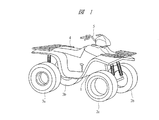
以下、本発明の実施の形態を図面に基づいて詳細に説明する。図1はバギー車とも言われるATVつまり全地形走行車の一例を示す斜視図であり、車体1には前輪2a,2bと後輪3a,3bが設けられており、鞍乗り型の座席4が車体1の中央部に設けられている。座席4に着座した乗員はハンドル5を操作して走行することになる。
Hereinafter, embodiments of the present invention will be described in detail with reference to the drawings. FIG. 1 is a perspective view showing an example of an ATV, which is also called a buggy vehicle, that is, an all-terrain vehicle. The vehicle body 1 is provided with
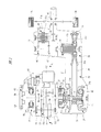
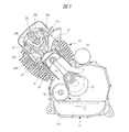
図2は図1に示された全地形走行車に搭載される動力伝達装置を示す概略図であり、図3は図2におけるA−A線に沿う方向の断面図である。図2に示すように、第1ケース体11aと第2ケース体11bとを突き合わせて組み立てられるクランクケース11にはクランク軸12が回転自在に装着されるとともに、図3に示すようにエンジン13が取り付けられている。エンジン13は、図3に示すように、クランクケース11に固定されるシリンダ14と、このシリンダ14の上端に固定されるシリンダヘッド15とを有している。シリンダ14に形成されたシリンダボア内にはピストン16が往復動自在に組み込まれ、クランク軸12にその回転中心から偏心した位置に固定されたクランクピン17とピストン16との間にはコネクティングロッド18が連結され、エンジン13によりクランク軸12は回転駆動される。
2 is a schematic view showing a power transmission device mounted on the all-terrain vehicle shown in FIG. 1, and FIG. 3 is a cross-sectional view taken along the line AA in FIG. As shown in FIG. 2, a
図3に示すように、シリンダヘッド15には燃焼室19に開口して吸気ポート21aが形成され、この吸気ポート21aを開閉するための吸気弁22aがシリンダヘッド15に装着されている。また、シリンダヘッド15には燃焼室19に開口して排気ポート21bが形成され、この排気ポート21bを開閉するための排気弁22bがシリンダヘッド15に装着されている。シリンダヘッド15には、カムシャフト23が回転自在に装着され、これと平行に設けられたロッカシャフト24には、吸気弁22aを開閉駆動するためのロッカアーム25aと、排気弁22bを開閉駆動するためのロッカアーム25bとが回動自在に装着されている。図2に示すように、クランク軸12にはスプロケット26が固定され、カムシャフト23に固定された図示しないスプロケットとの間にはタイミングチェーン(図示省略)が掛け渡されており、吸気弁22aと排気弁22bはクランク軸12の回転によりカムシャフト23およびロッカアーム25a,25bを介して所定のタイミングで開閉駆動される。
As shown in FIG. 3, the
図2に示すように、クランクケース11には変速機ケース31が取り付けられ、この変速機ケース31の内部にはベルト式の無段変速機32が組み込まれている。無段変速機32はクランク軸12に同軸状となって変速機ケース31内に回転自在に装着されるプライマリ軸33と、このプライマリ軸33に平行となって回転自在に変速機ケース31内に回転自在に装着されるセカンダリ軸34とを有し、プライマリ軸33はこれとクランク軸12との間に組み込まれる遠心クラッチ35のクラッチドラム36に連結されている。
As shown in FIG. 2, a
プライマリ軸33には溝幅可変のプライマリプーリ37が組み付けられており、プライマリプーリ37はプライマリ軸33に固定されてこれと一体に回転する固定プーリ37aと、プライマリ軸33に対して軸方向に移動自在に組み付けられてプライマリ軸33と一体に回転する可動プーリ37bとにより構成される。セカンダリ軸34には溝幅可変のセカンダリプーリ38が組み付けられており、セカンダリプーリ38はセカンダリ軸34に固定されてこれと一体に回転する固定プーリ38aと、セカンダリ軸34に対して軸方向に移動自在に組み付けられてセカンダリ軸34と一体に回転する可動プーリ38bとにより構成される。これらのプーリ37,38の間には、ゴム製のVベルト39が掛け渡されており、Vベルト39のプライマリプーリ37とセカンダリプーリ38とに対する巻き付け径が変化すると、プライマリ軸33の回転は無段階に変速比が変化してセカンダリ軸34に伝達される。プライマリプーリ37には、プライマリ軸33に固定されたカムプレート41により、プライマリ軸33の回転中心に対して直角方向を向いて円柱形状の遠心ウエイト42が複数個装着されており、セカンダリ軸34には、Vベルト39への締め付け力を加えるために、圧縮コイルばね43が装着されている。
A
したがって、クランク軸12が所定以上の回転数となって遠心クラッチ35を介してプライマリ軸33とクランク軸12とが締結された状態のもとで、プライマリ軸33の回転数が高くなると、遠心ウエイト42はこれに加わる遠心力により径方向外方に向けて移動し、プライマリプーリ37の溝幅が狭められてこのプーリ37に対する巻き付け径が大きくなる。これにより、セカンダリプーリ38の溝幅がばね力に抗して広がってVベルト39のセカンダリプーリ38に対する巻き付け径が小さくなり、無段変速機32の変速比は高速段側に変化する。
Therefore, when the rotation speed of the
クランク軸12とクラッチドラム36との間には、図2に示すように、ワンウエイクラッチつまり一方向クラッチ40が組み込まれており、一方向クラッチ40はクランク軸12の回転数がプライマリ軸33の回転数よりも高いときにはクランク軸12とプライマリ軸33とを接続させることなく開放状態とし、アクセルが戻された車両の減速時などのようにプライマリ軸33の回転数がクランク軸12の回転数よりも高くなるときにはプライマリ軸33をクランク軸12に接続させてエンジンブレーキを働かせることになる。
As shown in FIG. 2, a one-way clutch, that is, a one-way clutch 40 is incorporated between the
変速機ケース31には図2に示すようにギヤケース44が組み付けられ、このギヤケース44にはセカンダリ軸34が支持されるとともに、セカンダリ軸34に平行となって出力軸45が回転自在に装着され、さらに出力軸45に平行となって車軸46が回転自在に装着されており、車軸46は図1に示した後輪3a,3bに直接連結されている。セカンダリ軸34と出力軸45との間には、セカンダリ軸34に一体に設けられた歯車と出力軸45に回転自在に装着された歯車とからなる正転用の歯車列47が設けられるとともに、セカンダリ軸34に一体に設けられた歯車と出力軸45に回転自在に装着される歯車とこれに噛み合う図示しないアイドラー歯車とからなる逆転用の歯車列48が設けられている。
As shown in FIG. 2, a
出力軸45の回転方向を正転方向と逆転方向に切り換えるために、出力軸45には前後進切換機構49が装着されている。前後進切換機構49は、図2に示すように、出力軸45に設けられたスプラインにそれぞれ噛み合う切換ディスク51a,51bを有しており、これらの切換ディスク51a,51bは出力軸45に軸方向に摺動自在に装着されている。切換ディスク51aを歯車列47に係合させると、セカンダリ軸34の回転は正転方向となって車軸46に伝達され車両は前進移動する。一方、切換ディスク51bを歯車列48に係合させると、セカンダリ軸34の回転は逆転方向となって車軸46に伝達され、車両は後退移動する。
In order to switch the rotation direction of the
図2に示すように、クランクケース11にはクランク軸12に平行にバランサ軸52が回転自在に装着され、バランサ軸52はクランク軸12に固定された駆動歯車53aとバランサ軸52に固定された従動歯車53bとからなる歯車列53を介してクランク軸12に連結されている。バランサ軸52にはバランスウエイト54が一体に設けられるとともに、クランクケース11に装着されたオイルポンプ55のロータに連結されており、このオイルポンプ55から吐出される潤滑油は、動力伝達装置における摺動部に図示しない油路を介して供給されるようになっている。
As shown in FIG. 2, a
クランクケース11には、図2に示すように、発電体ケース56が取り付けられており、発電体ケース56内には発電体57が装着されるようになっており、発電体57はクランク軸12に取り付けられるアウターロータ58と、クランクケース11に取り付けられるステータ59とを有している。したがって、エンジン13が駆動されてクランク軸12が回転すると、発電体57により発電された電力が図示しないバッテリに充電される。
As shown in FIG. 2, a
エンジンを始動させるために、発電体ケース56内にはスタータ61が装着されており、このスタータ61はクランクケース11に取り付けられた電動モータ62により駆動されるようになっている。バッテリの充電量が不足してエンジン13をスタータ61により始動できないときに、手動でエンジン13を始動させるために、発電体ケース56内にはリコイルスタータ63が装着されている。リコイルスタータ63は、リコイルロープが巻き付けられたリコイルプーリ64を有し、リコイルロープを引いてリコイルプーリ64を回転させるとクランク軸12が回転し、エンジン13を手動でも始動させることができる。
In order to start the engine, a
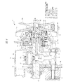
図4は図2の一部を拡大して示す断面図であり、図4に示すように、遠心クラッチ35はクラッチ入力軸としてのクランク軸12と、被駆動軸としてのプライマリ軸33との間に設けられており、クランク軸12に対して径方向を向いてクラッチドラム36内に組み込まれるインナープレート66を有している。このインナープレート66はクランク軸12にスプライン結合されるボス部67に一体に設けられており、ボス部67はクランク軸12にねじ結合されるナット68によりクランク軸12に締結されている。インナープレート66には、これに固定された支持ピン71により遠心ウエイトシュー72が回動自在に取り付けられており、遠心ウエイトシュー72にはその自由端の部分がクラッチドラム36の内面から離れる方向のばね力がコイルばね73により加えられている。したがって、クランク軸12の回転数が所定値以上となると、遠心力により遠心ウエイトシュー72は外方に回動してその自由端の部分がクラッチドラム36の内周面に接触してクラッチドラム36がクランク軸12と一体に回転し、その回転がプライマリ軸33に伝達される。
4 is an enlarged cross-sectional view showing a part of FIG. 2. As shown in FIG. 4, the centrifugal clutch 35 is provided between a
プライマリ軸33の内側端部には、フランジ部75aとジャーナル部75bとを有するクラッチ出力軸部75が一体となって設けられており、クラッチ出力軸部75のフランジ部75aはクラッチドラム36にかしめピン74により固定され、ジャーナル部75bには変速機ケース31の仕切り壁31aに取り付けられた軸受76が嵌合するようになっている。このクラッチ出力軸部75によりクラッチドラム36の回転が被駆動軸としてのプライマリ軸33に伝達される。クラッチ出力軸部75とボス部67との間には、前述した一方向クラッチ40が組み込まれている。また、プライマリ軸33の内側端部を支持する軸受76の外輪は、仕切り壁31aに取り付けられる蓋部材77により固定され、蓋部材77とジャーナル部75bとの間にはメカニカルシール78が組み込まれている。
A clutch
クラッチ出力軸部75にはクランク軸12の端部が入り込む凹部が形成され、この凹部内にはオイルポンプ80が組み込まれており、このオイルポンプ80はクランク軸12に固定されてクランク軸12により回転駆動されるインナーロータ81と、クラッチ出力軸部75に形成された凹部内に回転自在に装着されてインナーロータ81と噛み合うアウターロータ82とを有している。インナーロータ81とアウターロータ82は、クラッチ出力軸部75の凹部内に止めリング83により取り付けられる仕切り板84によりクラッチ出力軸部75に保持されている。
The clutch
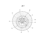
図5は図4におけるB−B線に沿う拡大断面図であり、このオイルポンプ80のインナーロータ81には外歯歯車が設けられ、アウターロータ82には内歯歯車が設けられており、オイルポンプ80は内接式のギヤポンプであり、インナーロータ81はクランク軸12の回転中心と一致した回転中心O1を中心に回転し、アウターロータ82はこの回転中心O1に対して偏心した回転中心O2を中心に回転する。それぞれの歯車はインボリュート歯形となっているが、トロコイド歯形のギヤポンプを用いるようにしても良い。クラッチ出力軸部75にはクランク軸12の軸心に潤滑油供給路85が形成され、この潤滑油供給路85はクランクピン17に形成された連通油路85aを介して図2に示したオイルポンプ55に連通しており、このオイルポンプ55から吐出した潤滑油が潤滑油供給路85に供給される。潤滑油供給路85に連通してオイルポンプ80に潤滑油を案内する吸入ポート86がクラッチ出力軸部75に形成され、仕切り板84にはオイルポンプ80から潤滑油を吐出する吐出ポート87が形成されている。この吐出ポート87から吐出された潤滑油は一方向クラッチ40に供給され、一方向クラッチ40から遠心クラッチ35の内部に供給される。
FIG. 5 is an enlarged cross-sectional view taken along the line BB in FIG. 4. The
エンジン13により駆動されるクランク軸12は、遠心クラッチ35を介してプライマリ軸33に連結されており、クランク軸12の回転数が所定値以上となると遠心クラッチ35を介してクランク軸12はプライマリ軸33に直結状態となるので、クランク軸12が所定の回転数以上となるまではクランク軸12とプライマリ軸33およびクラッチ出力軸部75とには回転差が発生し、回転差に応じて潤滑油が吐出ポート87から一方向クラッチ40および遠心クラッチ35に供給される。したがって、アイドリング時などのようにエンジンの低回転時には、クラッチドラム36とその内部に組み込まれた部材との間に相対移動が発生しており、一方向クラッチ40を構成する部材が摺動しているが、この状態のもとでは、オイルポンプ80から供給される潤滑油により確実に摺動部などの潤滑が行われる。
The
一方、クランク軸12の回転が上昇して遠心クラッチ35によりクランク軸12とプライマリ軸33とが直結状態となると、クランク軸12とプライマリ軸33とに回転差が発生せず、インナーロータ81とアウターロータ82とに回転差がなくなってオイルポンプ80は休止状態となって作動しなくなる。これにより、オイルポンプ80を駆動するための負荷がエンジン13に加わることが防止される。さらに、吸入ポート86に潤滑油供給路85から加わる潤滑圧によって潤滑油が吐出ポート87からは僅かに漏れる程度まで吐出量が低下し、一方向クラッチ40および遠心クラッチ35に供給される潤滑油の供給量が低下するが、そのときには、一方向クラッチ40および遠心クラッチ35を構成するそれぞれの部材には滑りがなくなるので、オイルポンプ80が作動停止しても部材の焼き付きなどの発生はない。しかも、オイルポンプ80の吸入ポート86にはバランサ軸52により駆動される常時駆動式のオイルポンプ55からオイルポンプ80以外の種々の摺動部などに潤滑油が供給されるようになっているが、一方向クラッチ40などに供給される潤滑油が低下した分だけ、他の部位に対して供給される潤滑油が増加するので、常時駆動式の主たるオイルポンプ55を小型化しても、エンジン高回転時や車両走行時に必要となる箇所に十分な潤滑油を供給することができる。
On the other hand, when the rotation of the
本発明は前記実施の形態に限定されるものではなく、その要旨を逸脱しない範囲で種々変更可能である。たとえば、本発明の動力伝達装置は、クランク軸12とベルト式無段変速機のプライマリ軸33とが同軸状に配置され、クランク軸12とプライマリ軸33との間に遠心クラッチ35と一方向クラッチ40が装着される2軸構成であるが、クランク軸とこれに平行に配置されて歯車列を介してクランク軸により駆動される副軸と、セカンダリ軸とが相互に平行となり、副軸に同軸状にプライマリ軸を配置した3軸構成のATV用の動力伝達装置にも本発明を適用することができる。その場合には、副軸をクラッチ入力軸とし、プライマリ軸を被駆動軸として、これらの間に遠心クラッチと一方向クラッチとが組み込まれることになる。
The present invention is not limited to the above-described embodiment, and various modifications can be made without departing from the scope of the invention. For example, in the power transmission device of the present invention, the
11 クランクケース
12 クランク軸(クラッチ入力軸)
32 ベルト式無段変速機
33 プライマリ軸(被駆動軸)
34 セカンダリ軸
35 遠心クラッチ
36 クラッチドラム
37 プライマリプーリ
40 一方向クラッチ
66 インナープレート
72 遠心ウエイトシュー
75 クラッチ出力軸部
80 オイルポンプ
81 インナーロータ
82 アウターロータ
84 仕切り板
85 潤滑油供給路
86 吸入ポート
87 吐出ポート
11 Crankcase 12 Crankshaft (clutch input shaft)
32 Belt type continuously
34
Claims (4)
前記クラッチ入力軸に固定され当該クラッチ入力軸により回転駆動されるインナーロータと、
前記遠心クラッチのクラッチドラムの回転を前記被駆動軸に伝達するクラッチ出力軸部に回転自在に装着され、前記インナーロータとともにオイルポンプを構成するアウターロータとを有し、
前記クラッチ入力軸と前記被駆動軸とに回転差がないときには前記遠心クラッチに対する潤滑油の供給量を減らすことを特徴とするクラッチの潤滑装置。 A clutch input shaft driven by the engine, a driven shaft arranged coaxially with the clutch input shaft, and a rotational speed of the clutch input shaft provided between the clutch input shaft and the driven shaft is predetermined. A clutch lubrication device in a power transmission device having a centrifugal clutch that transmits rotation of the clutch input shaft to the driven shaft when the value becomes equal to or greater than a value;
An inner rotor fixed to the clutch input shaft and driven to rotate by the clutch input shaft;
An outer rotor that is rotatably mounted on a clutch output shaft portion that transmits the rotation of the clutch drum of the centrifugal clutch to the driven shaft, and constitutes an oil pump together with the inner rotor;
2. A clutch lubrication apparatus, comprising: reducing a supply amount of lubricating oil to the centrifugal clutch when there is no rotational difference between the clutch input shaft and the driven shaft.
The clutch lubrication device according to any one of claims 1 to 3, wherein the clutch input shaft is a crankshaft, and the driven shaft is a primary shaft of a continuously variable transmission. Lubrication device.
Priority Applications (1)
| Application Number | Priority Date | Filing Date | Title |
|---|---|---|---|
| JP2004111328A JP2005291473A (en) | 2004-04-05 | 2004-04-05 | Clutch lubrication equipment |
Applications Claiming Priority (1)
| Application Number | Priority Date | Filing Date | Title |
|---|---|---|---|
| JP2004111328A JP2005291473A (en) | 2004-04-05 | 2004-04-05 | Clutch lubrication equipment |
Publications (1)
| Publication Number | Publication Date |
|---|---|
| JP2005291473A true JP2005291473A (en) | 2005-10-20 |
Family
ID=35324616
Family Applications (1)
| Application Number | Title | Priority Date | Filing Date |
|---|---|---|---|
| JP2004111328A Pending JP2005291473A (en) | 2004-04-05 | 2004-04-05 | Clutch lubrication equipment |
Country Status (1)
| Country | Link |
|---|---|
| JP (1) | JP2005291473A (en) |
-
2004
- 2004-04-05 JP JP2004111328A patent/JP2005291473A/en active Pending
Similar Documents
| Publication | Publication Date | Title |
|---|---|---|
| JP4700260B2 (en) | Continuously variable transmission | |
| US7243564B2 (en) | Power transmission system of engine | |
| CN100510348C (en) | Engine | |
| CN101152839B (en) | Power transmission device | |
| US8147370B2 (en) | Power unit for motorcycle | |
| CN1519142B (en) | Power Transmission Devices for Small Vehicles | |
| US8512181B2 (en) | Power unit for small vehicle | |
| JP2005319920A (en) | Engine power transmission device | |
| JP2005291472A (en) | Engine power transmission device | |
| CN101153556B (en) | Power transmission device | |
| US7823667B2 (en) | Power unit for small vehicle | |
| JP2003004108A (en) | Power transmission device for vehicles | |
| JP2005291473A (en) | Clutch lubrication equipment | |
| JP4494235B2 (en) | Clutch lubrication equipment | |
| CN100464092C (en) | Transmission gear with variable pulley | |
| US20040209725A1 (en) | Power transmission system of engine | |
| JPS63103784A (en) | Internal combustion engine | |
| CN101152840A (en) | transmission | |
| JP2005321054A (en) | Engine power transmission device | |
| JP2004308747A (en) | Breather device | |
| JP6542828B2 (en) | Internal combustion engine | |
| JP2003293786A (en) | engine | |
| JP2000265849A (en) | Power generation equipment for vehicles | |
| JP2004286186A (en) | Engine power transmission | |
| JP2004293477A (en) | Engine breather device |