EP1564441B1 - V-belt type variable speed drive - Google Patents
V-belt type variable speed drive Download PDFInfo
- Publication number
- EP1564441B1 EP1564441B1 EP03730860.8A EP03730860A EP1564441B1 EP 1564441 B1 EP1564441 B1 EP 1564441B1 EP 03730860 A EP03730860 A EP 03730860A EP 1564441 B1 EP1564441 B1 EP 1564441B1
- Authority
- EP
- European Patent Office
- Prior art keywords
- half body
- pulley half
- driven
- belt
- driving side
- Prior art date
- Legal status (The legal status is an assumption and is not a legal conclusion. Google has not performed a legal analysis and makes no representation as to the accuracy of the status listed.)
- Expired - Lifetime
Links
- 230000005540 biological transmission Effects 0.000 claims description 65
- 230000009467 reduction Effects 0.000 claims description 51
- 238000000034 method Methods 0.000 claims description 4
- 230000003247 decreasing effect Effects 0.000 claims 2
- 238000004804 winding Methods 0.000 description 35
- 238000005299 abrasion Methods 0.000 description 22
- 230000007423 decrease Effects 0.000 description 20
- 230000001105 regulatory effect Effects 0.000 description 19
- 230000007246 mechanism Effects 0.000 description 11
- 230000008859 change Effects 0.000 description 10
- 239000011347 resin Substances 0.000 description 5
- 229920005989 resin Polymers 0.000 description 5
- 238000002485 combustion reaction Methods 0.000 description 3
- 230000008878 coupling Effects 0.000 description 2
- 238000010168 coupling process Methods 0.000 description 2
- 238000005859 coupling reaction Methods 0.000 description 2
- 230000009286 beneficial effect Effects 0.000 description 1
- 238000001816 cooling Methods 0.000 description 1
- 230000006872 improvement Effects 0.000 description 1
- 230000004048 modification Effects 0.000 description 1
- 238000012986 modification Methods 0.000 description 1
Images


Classifications
-
- F—MECHANICAL ENGINEERING; LIGHTING; HEATING; WEAPONS; BLASTING
- F16—ENGINEERING ELEMENTS AND UNITS; GENERAL MEASURES FOR PRODUCING AND MAINTAINING EFFECTIVE FUNCTIONING OF MACHINES OR INSTALLATIONS; THERMAL INSULATION IN GENERAL
- F16H—GEARING
- F16H9/00—Gearings for conveying rotary motion with variable gear ratio, or for reversing rotary motion, by endless flexible members
- F16H9/02—Gearings for conveying rotary motion with variable gear ratio, or for reversing rotary motion, by endless flexible members without members having orbital motion
- F16H9/04—Gearings for conveying rotary motion with variable gear ratio, or for reversing rotary motion, by endless flexible members without members having orbital motion using belts, V-belts, or ropes
- F16H9/12—Gearings for conveying rotary motion with variable gear ratio, or for reversing rotary motion, by endless flexible members without members having orbital motion using belts, V-belts, or ropes engaging a pulley built-up out of relatively axially-adjustable parts in which the belt engages the opposite flanges of the pulley directly without interposed belt-supporting members
- F16H9/16—Gearings for conveying rotary motion with variable gear ratio, or for reversing rotary motion, by endless flexible members without members having orbital motion using belts, V-belts, or ropes engaging a pulley built-up out of relatively axially-adjustable parts in which the belt engages the opposite flanges of the pulley directly without interposed belt-supporting members using two pulleys, both built-up out of adjustable conical parts
- F16H9/18—Gearings for conveying rotary motion with variable gear ratio, or for reversing rotary motion, by endless flexible members without members having orbital motion using belts, V-belts, or ropes engaging a pulley built-up out of relatively axially-adjustable parts in which the belt engages the opposite flanges of the pulley directly without interposed belt-supporting members using two pulleys, both built-up out of adjustable conical parts only one flange of each pulley being adjustable
-
- F—MECHANICAL ENGINEERING; LIGHTING; HEATING; WEAPONS; BLASTING
- F16—ENGINEERING ELEMENTS AND UNITS; GENERAL MEASURES FOR PRODUCING AND MAINTAINING EFFECTIVE FUNCTIONING OF MACHINES OR INSTALLATIONS; THERMAL INSULATION IN GENERAL
- F16H—GEARING
- F16H55/00—Elements with teeth or friction surfaces for conveying motion; Worms, pulleys or sheaves for gearing mechanisms
- F16H55/32—Friction members
- F16H55/52—Pulleys or friction discs of adjustable construction
- F16H55/56—Pulleys or friction discs of adjustable construction of which the bearing parts are relatively axially adjustable
-
- F—MECHANICAL ENGINEERING; LIGHTING; HEATING; WEAPONS; BLASTING
- F16—ENGINEERING ELEMENTS AND UNITS; GENERAL MEASURES FOR PRODUCING AND MAINTAINING EFFECTIVE FUNCTIONING OF MACHINES OR INSTALLATIONS; THERMAL INSULATION IN GENERAL
- F16H—GEARING
- F16H63/00—Control outputs from the control unit to change-speed- or reversing-gearings for conveying rotary motion or to other devices than the final output mechanism
- F16H63/02—Final output mechanisms therefor; Actuating means for the final output mechanisms
- F16H63/04—Final output mechanisms therefor; Actuating means for the final output mechanisms a single final output mechanism being moved by a single final actuating mechanism
- F16H63/06—Final output mechanisms therefor; Actuating means for the final output mechanisms a single final output mechanism being moved by a single final actuating mechanism the final output mechanism having an indefinite number of positions
- F16H63/067—Final output mechanisms therefor; Actuating means for the final output mechanisms a single final output mechanism being moved by a single final actuating mechanism the final output mechanism having an indefinite number of positions mechanical actuating means
-
- F—MECHANICAL ENGINEERING; LIGHTING; HEATING; WEAPONS; BLASTING
- F16—ENGINEERING ELEMENTS AND UNITS; GENERAL MEASURES FOR PRODUCING AND MAINTAINING EFFECTIVE FUNCTIONING OF MACHINES OR INSTALLATIONS; THERMAL INSULATION IN GENERAL
- F16H—GEARING
- F16H61/00—Control functions within control units of change-speed- or reversing-gearings for conveying rotary motion ; Control of exclusively fluid gearing, friction gearing, gearings with endless flexible members or other particular types of gearing
- F16H61/66—Control functions within control units of change-speed- or reversing-gearings for conveying rotary motion ; Control of exclusively fluid gearing, friction gearing, gearings with endless flexible members or other particular types of gearing specially adapted for continuously variable gearings
- F16H61/662—Control functions within control units of change-speed- or reversing-gearings for conveying rotary motion ; Control of exclusively fluid gearing, friction gearing, gearings with endless flexible members or other particular types of gearing specially adapted for continuously variable gearings with endless flexible members
- F16H2061/66295—Control functions within control units of change-speed- or reversing-gearings for conveying rotary motion ; Control of exclusively fluid gearing, friction gearing, gearings with endless flexible members or other particular types of gearing specially adapted for continuously variable gearings with endless flexible members characterised by means for controlling the geometrical interrelationship of pulleys and the endless flexible member, e.g. belt alignment or position of the resulting axial pulley force in the plane perpendicular to the pulley axis
Definitions
- the present invention relates to a V-belt continuously variable transmission according to the preamble of independent claim 1. Further, the invention relates to a method for operating a V-belt continuously variable transmission according to the preamble of independent claim 7.
- US 3 962 928 A is considered as the closest prior art for claims 1 and 7.
- a V belt type continuously variable transmission may be adopted as a power transmission mechanism for transmitting an engine power to a rear wheel. In this type of V belt type continuously variable transmission, as shown in Figs.
- a structure is in general use in which a drive pulley 103, which is mounted on a crankshaft (input shaft) 100 and has a driving side fixed pulley half body 101 and a driving side movable pulley half body 102, and a driven pulley 107, which is mounted on an output shaft 104 and has a driven side fixed pulley half body 105 and a driven side movable pulley half body 106, are coupled by a V belt 108.
- a weight 109 moves the driving side movable pulley half body 102 to the side of the fixedpulleyhalf body 101 with a centrifugal force as an engine speed increases, and with this movement, the driven side movable pulley half body 106 of the driven pulley 107 moves in a direction apart from the fixed pulley half body 105 while compressing a spring 110. Consequently, a winding diameter of the drive pulley 103 increases and a winding diameter of the driven pulley 107 decreases, and a reduction gear ratio decreases to a reduction gear ratio at top time which is a minimum reduction gear ratio.
- the present invention has been devised in view of the above-mentionedcircumstances, and it is an object of the present invention to provide a V belt type continuously variable transmission which can restrain deviation of a reduction gear ratio due to abrasion of a V belt to secure a vehicle speed at the same engine speed and can extend a replacement period of the V belt.
- the V belt type continuously variable transmission is further characterized in that the driven side stopper is constituted by bringing a boss portion of the driven side movable pulley half body into abutment against a spring bearing member fixed to the output shaft.
- the V-belt continuously variable transmission is characterized in that the driving side stopper is constituted by bringing the weight into abutment against a stopper portion formed in an outer edge portion of the driving side movable pulley half body to regulate a position in radial direction of the weight.
- the V-belt continuously variable transmission is characterized in that the driving side stopper is constituted by bringing a boss portion of the driving side movable pulley half body into abutment against a boss portion of the driving side fixed pulley half body.
- the V-belt continuously variable transmission is preferably characterized according to another in embodiment that the driven side movable pulley half body is adapted to be movable in the axial direction and rotate together with the output shaft by engaging a guide pin implanted in the output shaft with a slide groove of the driven side movable pulley half body, and the driven side stopper brings the end of the slide groove of the driven side movable pulley half body into abutment with the guide pin.
- the reduction gear ratio changes to be smaller by an amount of abrasion of the V-belt.
- Figs. 1 to 6 are views for explaining a V belt type continuously variable transmission according to an embodiment of the present invention.
- Fig. 1 is a left side view of a motorcycle mounted with the V belt type continuously variable transmission of this embodiment
- Fig. 2 is a sectional plan view of an engine unit provided with the V belt type continuously variable transmission
- Fig. 3 is a sectional plan view of the V belt type continuously variable transmission
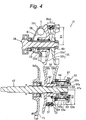
- Figs. 4 , 5 , and 6 are sectional views showing a change in a winding diameter due to abrasion of a V belt, respectively.
- the front and rear and the left and right in this embodiment means the front and rear and the left and right viewed from a person sitting on a sheet.
- reference numeral 1 denotes a motorcycle, which has a schematic structure in which front forks 5 having a front wheel 4 axially supported thereon by head pipes 3, which is locked to a front end of a body frame 1a, are supported so as to be pivotable to the left and right, rear arms 8 having a rear wheel 7 axially supported thereon is supported from a rear armbracket 6, which is locked in a central part of themotorcycle, so as to be swingable vertically, and a sheet 9 including a driver sheet portion 9a and a rear passenger sheet portion 9b is arranged in an upper part of the body frame 1a.
- the body frame 1a includes left and right down tubes 1b extending obliquely downward from the head pipes 3, left and right upper tubes 1c following rear ends of the respective down tubes 1b and extending obliquely upward, and left and right sheet rails 1d traversed in a longitudinal direction between the down tubes 1b and the upper tubes 1c and joined thereto.
- the body frame 1a is covered by a body cover 10 made of resin including a front cover 10a, a leg shield 10b, a side cover 10c, and the like.
- a steering handlebar 11 is fixed to an upper end of the front fork 5 and is covered by a handle cover 11a.
- a rear cushion 12 is suspended between the rear arms 8 and the rear arm bracket 6.
- An engine unit 2 is suspended and supported by the down tubes 1b of the body frame 1a.
- This engine unit 2 is provided with an air-cooling four-cycle single cylinder engine 15, which is mounted with a cylinder axial line A slanted approximately 45 degrees to the front, a V belt type continuously variable transmission 16, a multiple wet centrifugal clutch mechanism 17, and a reduction gear mechanism 18.
- the engine 15 has a schematic structure in which a cylinder head 20 is connected to an upper interface of a cylinder block 19 and a crankcase 22 housing a crankshaft 28 is connected to a lower interface of the cylinder block 19.
- a suction port (not shown) communicating with a combustion recessed portion 20a is opened on a rear surface of the cylinder head 20, and a carburetor 23 is connected to the suction port via a suction pipe 23a.
- an exhaust port (not shown) communicating with the combustion recessed portion 20a is opened on a front surface of the cylinder head 20, and an exhaust pipe 24 is connected to the exhaust port.
- This exhaust pipe 24 extends downward to the rear of the engine 15 and, then, extends obliquely backward through a right side thereof, and is connected to a muffler 25 disposed on a right side of the rear wheel 7.
- a spark plug 30 is inserted in the combustion recessed portion 20a.
- a chain chamber 19a communicating with the inside of the crankcase 22 and the inside of the cylinder head 20 is formed in a left portion of the cylinder block 19, a timing chain 34, which drives to rotate a cam shaft 31 with the crankshaft 28, is disposed in the chain chamber 19a, and a not-shown suction valve and a not-shown exhaust valve is driven to open and close by this cam shaft 31.
- a piston 26 is slidably inserted and arranged in a cylinder bore of the cylinder block 19.
- a small end 27b of a connection rod 27 is coupled to the piston 26, and a large end 27a of the connection rod 27 is coupled to a crankpin 29 which is fit between left and right crank arms 28a and 28b of the crankshaft 28.
- a transmission shaft 47 is arranged behind the crankshaft 28 in parallel with the crankshaft 28, and a drive shaft 48 is arranged on the left in an axial direction of the transmission shaft 47 so as to be coaxial.
- a drive sprocket 49 is mounted at a left end of this drive shaft 48, and the drive sprocket 49 is coupled to a driven sprocket 51 of the rear wheel 7 via a chain 50.
- a generator 42 is mounted at a left end of the crankshaft 28.
- This generator has a structure in which a rotor 42a is locked to a sleeve 43, which is fitted to the crankshaft 28 in a tapered manner, and a stator 42b opposed to the rotor 42a is fixed to a generator case 44.
- the crankcase 22 is divided into a first case 40 on the left and a second case 41 on the right in a crankshaft direction.
- the generator case 44 housing the generator 42 is detachably mounted on the outer side in the crankshaft direction of this first case 40, and a transmission case 45 housing the V belt type continuously variable transmission 16 is mounted on the outer side in the crankshaft direction of the second case 41.
- the centrifugal clutch mechanism 17 is multiple wet type and has a schematic structure in which a bowl-like outer clutch 83 is spline-fitted so as to rotate with the transmission shaft 47, an inner clutch 84 is arranged coaxially on the inner side in an axial direction of the outer clutch 83, and the inner clutch 84 is spline-fitted to a primary reduction small gear 74, which is rotatably mounted on the transmission shaft 47, so as to rotate with the same.
- outer clutch plates 85 are arranged in the outer clutch 83, two pressing plates 86, 86 are arranged so as to be located at both ends thereof, and both the clutch plates 85 and the pressing plates 86 are engaged in the outer clutch 83 so as to rotate with the outer clutch 83.
- inner clutch plates 87 are arranged between the outer clutch plates 85 and the pressing plates 86, and the respective inner clutch plates 87 are engaged with an external periphery of the inner clutch 84 so as to rotate with the inner clutch 84.
- a cam surface 83a is formed on the inner side of the outer clutch 83, and a weight 88 is disposed between the cam surface 83a and the pressing plate 86 on the outer side.
- This weight 88 is moved in a clutch connection direction by the cam surface 83a as it moves to the outer side in a radial direction by a centrifugal force of the outer clutch 83, and presses to move the pressing plates 86 to bring the outer clutch plates 85 and the inner clutch plates 86 into a connected state with each other.
- a part above an axial line of the centrifugal clutch mechanism 17 shows an interrupted state and a part below the axial line shows a connected state.
- the reduction gear mechanism 18 has a structure in which a reduction shaft 52 is disposed in parallel with the transmission shaft 47, the primary reduction small gear 74 is mounted on the transmission shaft 47 so as to be rotatable relatively, a primary reduction large gear 75, which engages with the primary reduction small gear 74, is coupled to the reduction shaft 52, a secondary reduction small gear 52a is integrally formed with the reduction gear 52, and a secondary reduction large gear 48a, which engages with the secondary reduction small gear 52a, is integrally formed with the drive shaft 48.
- the drive shaft 48 is disposed on an identical axial line with the transmission shaft 47.
- the transmission case 45 is a case of a substantially closed structure, which is formed independently from the crankcase 22, and has an elliptical shape covering most parts of the upper side of the crankcase 22 viewed from a right side thereof.
- the transmission case 45 includes a case main body 45a of a bottomed box shape opening to the outer side in the crankshaft direction and a cover 45b closing the opening of the case main body 45a airtightly, and is tightened with and fixed to the second case 41 by a bolt 70.
- a gap "a” is provided between a bottom wall 45c of the case main body 45a and the second case 41, and heat from the engine 15 is restrained from transmitting to the transmission case 45 by this gap "a".
- An opening 41e having a size allowing the centrifugal clutch mechanism 17 to be taken in and out is formed on the axial direction of the second case 41.
- This opening 41e is closed by a clutch cover 71 airtightly, and the clutch cover 71 is detachably tightened and fixed to an opening edge of the second case 41 by a bolt 72. Consequently, the centrifugal clutchmechanism 17 canbe removed together with the transmission shaft 47 by removing the transmission case 45 together with a driven pulley 56 of the V belt type continuously variable transmission 16 and removing the clutch cover 71.
- the V belt type continuously variable transmission 16 has a structure in which a drive pulley 55 is mounted on a right outer end of the crank shaft (input shaft) 28, a driven pulley 56 is mounted on a right outer end of the transmission shaft (output shaft) 47, and a V belt 57 is wound around and coupled to both the pulleys 55, 56.
- the V belt 57 is a belt made of resin having heat resistance and durability and is formed by arranging a large number of resin blocks 57a of a lateral H shape and coupling these resin blocks with a pair of annular coupling members 57b made of heat-resistant rubber. Note that it is also possible to adopt a belt made of rubber as the V belt.
- the drive pulley 55 has a driving side fixed pulley half body 55a fixed to the right end of the crankshaft 28, and a driving side movable pulley half body 55b which is disposed so as to be slidable in an axial direction to the inner side in the crankshaft direction of the fixed pulley half body 55a and rotate together with the crankshaft 28 via a slide collar 59.
- a cam plate 58 is disposed on the inner side in the crankshaft direction of the driving side movable pulley half body 55b.
- This cam plate 58 and the slide collar 59 are mounted on the right end of the crankshaft 28 by spline fitting, and the driving side fixed pulley half body 55a is mounted on the outer side in the axial direction thereof and fastened and fixed by a lock nut 60.
- a cylindrical boss portion 55d which is integrally formed with an axial part of the driving side movable pulley half body 55b, is mounted on the slide collar 59 so as to be movable in the axial direction.
- a cylindrical weight 61 is disposed between the driving side movable pulley half body 55b and the cam plate 58.
- the driven pulley 56 has a driven side fixed pulley half body 56a fixed to the right outer end of the transmission shaft 47 and a driven side movable pulley half body 56b which is disposed on the outer side in the crankshaft direction of the fixed pulley half body 56a so as to be slidable in the axial direction.
- a cylindrical slide collar 62 is locked to an axial part of the driven side fixed pulley half body 56a, and the slide collar 62 is mounted on the transmission shaft 47 by spline fitting.
- a cylindrical boss portion 63 locked to an axial part of the driven side movable pulley half body 56b is mounted on this slide collar 62 so as to be movable in the axial direction.
- Plural slide grooves 63a extending in the axial direction is formed in the boss portion 63, and a guide pin 64, which is implanted and fixed to the slide collar 62, is engaged with the slide grooves 63a, whereby the driven side movable pulley half body 56b rotates together with the fixed pulley half body 56a.
- a spring bearing member 65 consisting of an annular plate is fixed to an outer end of the slide collar 62 by a circlip 65a, and a coil spring 67, which always biases the driven side movable pulley half body 56b to the side of the fixed pulley half body 56a, is provided between this spring bearing member 65 and the driven side movable pulley half body 56b.
- the weight 61 is moved to the outer side in the radial direction by a centrifugal force to move the driving side movable pulley half body 55b to the outer side in the axial direction, whereby a winding diameter of the pulley increases.
- the driven side movable pulley half body 56b compresses the coil spring 67 to move to the outer side in the axial direction, whereby the winding diameter of the pulley decreases and a reduction gear ratio decreases.
- the driven pulley 56 is fastened and fixed to the transmission shaft 47 by a lock nut 66 screwed into a tip 47a of the transmission shaft 47.
- This lock nut 66 is inserted and arranged so as to sink into an outer end 62a of the slide collar 62.
- an inner diameter of the slide collar 62 is set to be larger stepwise than an outer diameter of the transmission shaft 47, and the tip 47a of the transmission shaft 47 is set to be smaller stepwise. Consequently, the lock nut 66 and a washer can be inserted and arranged in the outer ends 62a of the slide collar 62 without any trouble and, in this way, it becomes possible to locate the lock nut 66 on the inner side in the crankshaft direction than the spring bearing member 65 of the coil spring 67. Since the transmission is constituted as described above, protrusion to the outer side in the transmission shaft direction can be reduced with a simple structure while a necessary length of the coil spring 67 is secured.
- a driven side stopper which regulates a position in the axial direction of the driven side movable pulley half body 56b to a top time position when a space between the driven side movable pulley half body 56b and the driven side fixed pulley 56a is maximized.
- This driven side stopper is constituted so as to regulate the space of the driven pulley 56 to the space at top time by bringing an outer end surface 63b of the boss portion 63 of the driven side movable pulley half body 56b into abutment against the spring bearing member 65.
- the driven side stopper may be constituted so as to regulate the space of the driven side pulley 56 to the space at the top time by bringing an end in axial direction 63a' of a slide groove 63a, which is formed in the boss portion 63 of the driven side movable pulley half body 56b, into abutment against the guide pin 64.
- a driving side stopper which regulates a position in the axial direction of the driving side variable pulley half body 55b to a corrected top time position (position shown in Fig. 5 ) where a space between the driving side movable pulley half body 55b and the driving side fixed pulley half body 55a is smaller than the space in a top time position (position shown in Fig. 4 ) where the space is minimized.
- This driving side stopper is constituted by integrally forming a stopper portion 55c, against which the weight 61 abuts, at an external periphery of the driving side movable pulley half body 55b on the inner side of the crankshaft direction, and regulates a position in the radial direction of the weight 61 with the stopper portion 55c and the cam plate 58 to thereby regulate a space of the drive pulley 55 to a space at corrected top time.
- the stopper portion 55c is set such that a gap b is formed between the stopper portion 55c and the weight 61 in a state in which the V belt 57 is substantially new and the driven side movable pulley 56b is regulated to the top time position.
- Figs. 7 to 9 are characteristic chart for explaining operations as well as actions and advantages of this embodiment, respectively.
- Fig. 7 shows a relation between a travel distance and a change in an upper width dimension due to abrasion of a V belt.
- the upper width dimension of the V belt decreases as the travel distance increases. Note that an amount of abrasion of this V belt is substantially the same as that of the conventional one.
- Fig. 8 shows a relation between a travel distance and a reduction gear ratio at top time.
- the reduction gear ratio changes to be smaller and, when the travel distance has generally reached a certain travel distance D1 km, the reduction gear ratio is reversed to change to be larger.
- the reduction gear ratio returns to the original reduction gear ratio and, then, the reduction gear ratio changes to be larger.
- the reduction gear ratio changes to be larger as the travel distance increases from an initial stage.
- Fig. 9 shows a relation between a travel distance and an engine speed at top time.
- the reduction gear ratio since the reduction gear ratio deviates to be larger from an initial stage, it is necessary to increase the engine speed in order to obtain a predetermined vehicle speed.
- the reduction gear ratio since the reduction gear ratio changes to be smaller up to the vicinity of the certain travel distance D1 km, the predetermined vehicle speed is obtained even at a low engine speed.
- the predetermined vehicle speed is obtained without increasing the engine speed until the travel distance exceeds the travel distance D2 km.
- the drive pulley 55 is in a position at low time where the space between the pulley half bodies is maximized and the winding diameter is minimized, and the driven pulley 55 is in a position at low time where the space between the pulley half bodies is minimized and the winding diameter is maximized by a biasing force of the coil spring 67, whereby the reduction gear ratio is maximized.
- the weight 61 moves the driving side movable pulley half body 55b to the side of the fixed pulley half body 55a with a centrifugal force, whereby the winding diameter of the drive pulley 55 gradually increases and the driven side movable pulley half body 56b compresses the coil spring 67 to move to the side of the fixed pulley half body 56a, the winding diameter of the driven pulley 56 gradually decreases and the reduction gear ratio gradually decreases.
- the driving side movable pulley half body 55b is moved by the centrifugal force of the weight 61 and the winding diameter of the drive pulley 55 further increases and, in accordance with this, the driven side movable pulley half body 56b moves to the outer side in the axial direction, and the outer end surface 63b of the boss portion 63 of the driven side movable pulley half body 56b abuts against the spring bearing member 65. Consequently, the driven pulley 56 is regulated to the top time position where the winding diameter is minimized. In this case, as shown in Fig. 4 , when the travel distance is zero or at the initial stage, the gap b exists between the weight 61 and the stopper portion 55c of the driving side movable pulley half body 55b.
- the V belt 57 is worn as shown in Fig. 7 , and the upper width dimension of the belt decreases.
- the upper width dimension of the V belt 57 decreases from L1 at the time when the V belt is new to L1'.
- the driving side movable pulley half body 55b moves to the side of the fixed pulley half body 55a by an amount of abrasion and the winding diameter of the drive pulley 55 slightly increases from R1 at the initial stage to R1', the weight 61 abuts against the stopper portion 55c, and the winding diameter increases to the winding diameter at corrected top time larger than that at top time to be regulated to this winding diameter.
- the driven side movable pulley half body 56b of the driven pulley 56 is regulated to the top time position, the V belt 57 moves to the axis side and the winding diameter slightly decreases from R2 at the initial stage to R2'. In this way, as shown in Fig. 8 , the reduction gear ratio changes to be smaller by an amount of abrasion of the V belt 57.
- the reduction gear ratio changes to be smaller from the state in which the V belt 57 is new up to the vicinity of the travel distance D1 km and, when the travel distance has exceeded D1 km, the reduction gear ratio starts to change to be larger in the vicinity of D2 km.
- the reduction gear ratio gradually changes to be larger.
- the driven side movable pulley half body 56b of the driven pulley 56 is regulated to the top time position where the winding diameter is minimized, in the period until the travel distance reaches, for example, D1 km as described above, the winding diameter of the drive pulley 55 changes to be larger in accordance with the increase in the travel distance and the winding diameter of the driven pulley 56 changes to be smaller, whereby the reduction gear ratio changes to be smaller.
- the driving side movable pulley half body 55b on the drive pulley 55 side is regulated to the corrected top time position, when the travel distance further increases exceeding D1 km, although the reduction gear ratio has been changing to be smaller to that point, the reduction gear ratio is reversed and changes to return to the original reduction gear ratio.
- the vehicle speed at top time does not decrease to the lower limit value even if the amount of abrasion of the V belt 57 increases considerably, the V belt 57 is not required to be changed at an amount of abrasion equivalent to that in the past, and the replacement period of the V belt can be extended.
- a standard for replacement of a V belt is set to a time when the travel distance has reached D2 km in the conventional transmission, whereas, in this embodiment, the replacement period is a time when the travel distance has reached D3 km.
- the top time position of the driven side movable pulley half body 56b is regulated by bringing the boss portion 63 of the driven side movable pulley half body 56b into abutment against the spring bearing member 65, and the top time position of the driving side movable pulley half body 55b is regulated by bringing the weight 61 into abutment against the stopper portion 55c of the driving side movable pulley half body 55b. Therefore, the driven side movable pulley half body 56b and the driving side movable pulley half body 55b can be regulated to the top time position and the corrected top time position with a simple structure without providing a separate component or a special stopper mechanism, and an increase in cost can be prevented.
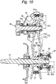
- Figs. 10 to 12 are views for explaining the driving side stopper according to the present invention.
- reference numerals and signs identical with those in Figs. 4 to 6 denote identical or equivalent components.
- the driving side stopper of this embodiment is an example in which a projecting portion 55e is formed on an outer end surface of the boss portion 55d of the driving side movable pulley half body 55b, and the projecting portion 55e is brought into abutment against a boss portion 55f of the fixed pulley half body 55a, whereby the driving side movable pulley half body 55b is regulated to the corrected top time position.
- the driving side movable pulley half body 55b can also be regulated to the corrected top time position with a simple structure without providing a separate component or a special stopper mechanism, and the same advantages as the above-mentioned embodiment can be obtained.
- a structure for bringing the driving side movable pulley half body 55b into abutment against the fixed pulley half body 55a to regulate it to the top time position is adopted, a pressing force can be prevented from acting on the Vbelt 57 by a centrifugal force of the weight 61, and abrasion of the V belt 57 can be restrained.
- the present invention is described with the case in which it is applied to a V belt type continuously variable transmission of a motorcycle as an example in the above-mentioned embodiment, a scope of application of the present invention is not limited to this, and the present invention can be applied to a V belt type continuously variable transmission for a vehicle such as a motor tricycle or a four wheel car.
- the present invention is described with a V belt of resin as an example in the above-mentioned embodiment, the present invention can be naturally applied to a V belt of rubber, and substantially the same advantages as the above-mentioned embodiment can be obtained in this case.
- the driven side movable pulley half body on the driven pulley side is regulated to the top time position where the winding diameter is minimized
- the driving side movable pulley half body on the drive pulley side is regulated to the corrected top time position where the winding diameter is maximized.
- the reduction gear ratio changes to increase in accordance with a further increase in the amount of abrasion.
- the reduction gear ratio changes to be smaller once and, then, changes to increase, whereby the number of rotations of the output shaft at top time does not decrease to a lower limit value until the amount of abrasion of the V belt becomes considerably large. As a result, a replacement period of the V belt can be extended.
- the driven side stopper is constituted by bringing the boss portion of the driven side movable pulley half body against the spring bearing member.
- the driven side stopper is constituted by bringing the end in axial direction of the slide groove of the driven side movable pulley half body. Therefore, the driven side movable pulley half body can be regulated to the top time position with a simple structure without providing a separate component or a special stopper mechanism, and an increase in cost can be prevented.
- the driving side stopper is constituted by bringing the weight into abutment against the stopper portion formed in the outer edge of the driving side movable pulley half body to regulate the position in radial direction of the weight.
- the driving side stopper is constituted by bringing the boss portion of the driving side movable pulley half body into abutment against the boss portion of the driving side fixed pulley half body. Therefore, as in claim 3, the driving side movable pulley half body can be regulated to the top time position with a simple structure without providing a separate component or a special stopper mechanism.
Landscapes
- Engineering & Computer Science (AREA)
- General Engineering & Computer Science (AREA)
- Mechanical Engineering (AREA)
- Transmissions By Endless Flexible Members (AREA)
Description
- The present invention relates to a V-belt continuously variable transmission according to the preamble of independent claim 1. Further, the invention relates to a method for operating a V-belt continuously variable transmission according to the preamble of independent claim 7.
US 3 962 928 A is considered as the closest prior art for claims 1 and 7. For example, in a scooter type motorcycle, a V belt type continuously variable transmission may be adopted as a power transmission mechanism for transmitting an engine power to a rear wheel. In this type of V belt type continuously variable transmission, as shown inFigs. 13(a) and 13(b) , a structure is in general use in which adrive pulley 103, which is mounted on a crankshaft (input shaft) 100 and has a driving side fixed pulley half body 101 and a driving side movablepulley half body 102, and a drivenpulley 107, which is mounted on anoutput shaft 104 and has a driven side fixedpulley half body 105 and a driven side movable pulleyhalf body 106, are coupled by aV belt 108. - In the V belt type continuously variable transmission, a
weight 109 moves the driving side movable pulleyhalf body 102 to the side of the fixedpulleyhalf body 101 with a centrifugal force as an engine speed increases, and with this movement, the driven side movable pulleyhalf body 106 of the drivenpulley 107 moves in a direction apart from the fixedpulley half body 105 while compressing aspring 110. Consequently, a winding diameter of thedrive pulley 103 increases and a winding diameter of the drivenpulley 107 decreases, and a reduction gear ratio decreases to a reduction gear ratio at top time which is a minimum reduction gear ratio. In this case, it is a general practice to regulate a position in axial direction of the driving side movablepulley half body 102 to a top time position by regulating a position in radial direction of the weight 109 (e.g., seeJP-A-8-178003 JP-A-8-178004 - However, in the case in which a structure for regulating a reduction gear ratio at top time on a drive pulley side as in the above-mentioned conventional transmission is adopted, a winding diameter of the drive pulley is reduced by an amount of abrasion of a V belt and, in accordance with this, a winding diameter on a driven pulley side increases. Therefore, there is a problem in that a reduction gear ratio deviates to the side of a reduction gear ratio at low time from the reduction gear ratio at top time, and a maximum speed decreases.
- For example, as shown in
Figs. 13(a) and 13(b) , in the case in which an upper width dimension is reduced from L1 at the time when theV belt 108 is new to L1' due to abrasion of theV belt 108 when the motorcycle has traveled a certain distance D2 km, the winding diameter of thedrive pulley 103 decreases from R1 in the top time position to R1' by an amount of this abrasion and the winding diameter of the drivenpulley 107 increases from R2 to R2' , and the reduction gear ratio increases from R2/R1 to R2' /R1' . As a result, since a vehicle speed at top time with the same engine decreases, the V belt has to be replaced even if an abrasion loss is within a tolerance. Thus, improvement is required in realizing extension of a replacement period. - The present invention has been devised in view of the above-mentionedcircumstances, and it is an object of the present invention to provide a V belt type continuously variable transmission which can restrain deviation of a reduction gear ratio due to abrasion of a V belt to secure a vehicle speed at the same engine speed and can extend a replacement period of the V belt.
- The inventive object is solved by the subject matter of independent claim 1.
- Preferably, the V belt type continuously variable transmission is further characterized in that the driven side stopper is constituted by bringing a boss portion of the driven side movable pulley half body into abutment against a spring bearing member fixed to the output shaft.
- Further, according to another beneficial embodiment, the V-belt continuously variable transmission is characterized in that the driving side stopper is constituted by bringing the weight into abutment against a stopper portion formed in an outer edge portion of the driving side movable pulley half body to regulate a position in radial direction of the weight. Moreover, in accordance with an advantageous embodiment, the V-belt continuously variable transmission is characterized in that the driving side stopper is constituted by bringing a boss portion of the driving side movable pulley half body into abutment against a boss portion of the driving side fixed pulley half body.
- Still further, the V-belt continuously variable transmission is preferably characterized according to another in embodiment that the driven side movable pulley half body is adapted to be movable in the axial direction and rotate together with the output shaft by engaging a guide pin implanted in the output shaft with a slide groove of the driven side movable pulley half body, and the driven side stopper brings the end of the slide groove of the driven side movable pulley half body into abutment with the guide pin.
- The inventive object is further solved by a method with the steps of independent claim 7.
- In a further inventive embodiment, the reduction gear ratio changes to be smaller by an amount of abrasion of the V-belt.
-
-
Fig. 1 is a left side view of a motor cycle mounted with a V belt type continuously variable transmission according to an embodiment of the present invention. -
Fig. 2 is a sectional plan view of an engine unit provided with the V belt type continuously variable transmission. -
Fig. 3 is a sectional plan view of the V belt type continuously variable transmission. -
Fig. 4 is a sectional view showing a change in a winding diameter due to abrasion of a Vbelt of theVbelt type continuously variable transmission. -
Fig. 5 is a sectional view showing a change in the winding diameter due to abrasion of the V belt. -
Fig. 6 is a sectional view showing a change in the winding diameter due to abrasion of the V belt. -
Fig. 7 is a characteristic chart showing a relation between a travel distance and an amount of abrasion of a V belt. -
Fig. 8 is a characteristic chart showing a relation between a travel distance and a reduction gear ratio at top time. -
Fig. 9 is a characteristic chart showing a relationbetween a travel distance and an engine speed at top time. -
Fig. 10 is a sectional view for explaining a driving side stopper according to an embodiment of an invention of claim 5. -
Fig. 11 is a sectional view showing a change in a winding diameter according to the driving side stopper. -
Fig. 12 is a sectional view showing a change in the winding diameter according to the driving side stopper. -
Fig. 13 is a view showing a conventional general V belt type continuously variable transmission. -
Fig. 14 is a sectional view showing a modification of a stopper of a driven side pulley in the embodiment. - Embodiments of the present invention will be hereinafter described based upon the accompanying drawings.
-
Figs. 1 to 6 are views for explaining a V belt type continuously variable transmission according to an embodiment of the present invention.Fig. 1 is a left side view of a motorcycle mounted with the V belt type continuously variable transmission of this embodiment,Fig. 2 is a sectional plan view of an engine unit provided with the V belt type continuously variable transmission,Fig. 3 is a sectional plan view of the V belt type continuously variable transmission,Figs. 4 ,5 , and6 are sectional views showing a change in a winding diameter due to abrasion of a V belt, respectively. Note that the front and rear and the left and right in this embodiment means the front and rear and the left and right viewed from a person sitting on a sheet. - In
Fig. 1 , reference numeral 1 denotes a motorcycle, which has a schematic structure in which front forks 5 having afront wheel 4 axially supported thereon by head pipes 3, which is locked to a front end of a body frame 1a, are supported so as to be pivotable to the left and right,rear arms 8 having a rear wheel 7 axially supported thereon is supported from a rear armbracket 6, which is locked in a central part of themotorcycle, so as to be swingable vertically, and asheet 9 including adriver sheet portion 9a and a rearpassenger sheet portion 9b is arranged in an upper part of the body frame 1a. - The body frame 1a includes left and right down
tubes 1b extending obliquely downward from the head pipes 3, left and right upper tubes 1c following rear ends of the respective downtubes 1b and extending obliquely upward, and left andright sheet rails 1d traversed in a longitudinal direction between thedown tubes 1b and the upper tubes 1c and joined thereto. In addition, the body frame 1a is covered by abody cover 10 made of resin including afront cover 10a, aleg shield 10b, aside cover 10c, and the like. - A
steering handlebar 11 is fixed to an upper end of the front fork 5 and is covered by a handle cover 11a. In addition, arear cushion 12 is suspended between therear arms 8 and the rear arm bracket 6. - An
engine unit 2 is suspended and supported by thedown tubes 1b of the body frame 1a. Thisengine unit 2 is provided with an air-cooling four-cyclesingle cylinder engine 15, which is mounted with a cylinder axial line A slanted approximately 45 degrees to the front, a V belt type continuouslyvariable transmission 16, a multiple wetcentrifugal clutch mechanism 17, and areduction gear mechanism 18. - The
engine 15 has a schematic structure in which acylinder head 20 is connected to an upper interface of acylinder block 19 and acrankcase 22 housing acrankshaft 28 is connected to a lower interface of thecylinder block 19. - A suction port (not shown) communicating with a combustion recessed portion 20a is opened on a rear surface of the
cylinder head 20, and acarburetor 23 is connected to the suction port via asuction pipe 23a. In addition, an exhaust port (not shown) communicating with the combustion recessed portion 20a is opened on a front surface of thecylinder head 20, and anexhaust pipe 24 is connected to the exhaust port. Thisexhaust pipe 24 extends downward to the rear of theengine 15 and, then, extends obliquely backward through a right side thereof, and is connected to amuffler 25 disposed on a right side of the rear wheel 7. Aspark plug 30 is inserted in the combustion recessed portion 20a. - A
chain chamber 19a communicating with the inside of thecrankcase 22 and the inside of thecylinder head 20 is formed in a left portion of thecylinder block 19, atiming chain 34, which drives to rotate acam shaft 31 with thecrankshaft 28, is disposed in thechain chamber 19a, and a not-shown suction valve and a not-shown exhaust valve is driven to open and close by thiscam shaft 31. - A
piston 26 is slidably inserted and arranged in a cylinder bore of thecylinder block 19. Asmall end 27b of aconnection rod 27 is coupled to thepiston 26, and alarge end 27a of theconnection rod 27 is coupled to acrankpin 29 which is fit between left andright crank arms crankshaft 28. - A
transmission shaft 47 is arranged behind thecrankshaft 28 in parallel with thecrankshaft 28, and adrive shaft 48 is arranged on the left in an axial direction of thetransmission shaft 47 so as to be coaxial. Adrive sprocket 49 is mounted at a left end of thisdrive shaft 48, and thedrive sprocket 49 is coupled to a drivensprocket 51 of the rear wheel 7 via achain 50. - A
generator 42 is mounted at a left end of thecrankshaft 28. This generator has a structure in which arotor 42a is locked to asleeve 43, which is fitted to thecrankshaft 28 in a tapered manner, and astator 42b opposed to therotor 42a is fixed to agenerator case 44. - The
crankcase 22 is divided into afirst case 40 on the left and asecond case 41 on the right in a crankshaft direction. Thegenerator case 44 housing thegenerator 42 is detachably mounted on the outer side in the crankshaft direction of thisfirst case 40, and atransmission case 45 housing the V belt type continuouslyvariable transmission 16 is mounted on the outer side in the crankshaft direction of thesecond case 41. - The
centrifugal clutch mechanism 17 is multiple wet type and has a schematic structure in which a bowl-likeouter clutch 83 is spline-fitted so as to rotate with thetransmission shaft 47, aninner clutch 84 is arranged coaxially on the inner side in an axial direction of theouter clutch 83, and theinner clutch 84 is spline-fitted to a primary reductionsmall gear 74, which is rotatably mounted on thetransmission shaft 47, so as to rotate with the same. - Plural
outer clutch plates 85 are arranged in theouter clutch 83, twopressing plates clutch plates 85 and thepressing plates 86 are engaged in theouter clutch 83 so as to rotate with theouter clutch 83. In addition,inner clutch plates 87 are arranged between theouter clutch plates 85 and thepressing plates 86, and the respectiveinner clutch plates 87 are engaged with an external periphery of theinner clutch 84 so as to rotate with theinner clutch 84. - A cam surface 83a is formed on the inner side of the outer clutch 83, and a
weight 88 is disposed between the cam surface 83a and thepressing plate 86 on the outer side. Thisweight 88 is moved in a clutch connection direction by the cam surface 83a as it moves to the outer side in a radial direction by a centrifugal force of the outer clutch 83, and presses to move thepressing plates 86 to bring the outerclutch plates 85 and the innerclutch plates 86 into a connected state with each other. Note that, inFigs. 2 and3 , a part above an axial line of the centrifugalclutch mechanism 17 shows an interrupted state and a part below the axial line shows a connected state. - The
reduction gear mechanism 18 has a structure in which areduction shaft 52 is disposed in parallel with thetransmission shaft 47, the primary reductionsmall gear 74 is mounted on thetransmission shaft 47 so as to be rotatable relatively, a primary reductionlarge gear 75, which engages with the primary reductionsmall gear 74, is coupled to thereduction shaft 52, a secondary reductionsmall gear 52a is integrally formed with thereduction gear 52, and a secondary reductionlarge gear 48a, which engages with the secondary reductionsmall gear 52a, is integrally formed with thedrive shaft 48. - The
drive shaft 48 is disposed on an identical axial line with thetransmission shaft 47. Asupport hole 48b, in which a left end of thetransmission shaft 47 is inserted, is recessed at a right end of thisdrive shaft 48, and the right end of thedrive shaft 48 is axially supported by thetransmission shaft 47 via abearing 76 mounted in thesupport hole 48b. - The
transmission case 45 is a case of a substantially closed structure, which is formed independently from thecrankcase 22, and has an elliptical shape covering most parts of the upper side of thecrankcase 22 viewed from a right side thereof. Thetransmission case 45 includes a casemain body 45a of a bottomed box shape opening to the outer side in the crankshaft direction and acover 45b closing the opening of the casemain body 45a airtightly, and is tightened with and fixed to thesecond case 41 by abolt 70. A gap "a" is provided between abottom wall 45c of the casemain body 45a and thesecond case 41, and heat from theengine 15 is restrained from transmitting to thetransmission case 45 by this gap "a". - An opening 41e having a size allowing the centrifugal
clutch mechanism 17 to be taken in and out is formed on the axial direction of thesecond case 41. This opening 41e is closed by aclutch cover 71 airtightly, and theclutch cover 71 is detachably tightened and fixed to an opening edge of thesecond case 41 by abolt 72. Consequently, thecentrifugal clutchmechanism 17 canbe removed together with thetransmission shaft 47 by removing thetransmission case 45 together with a drivenpulley 56 of the V belt type continuouslyvariable transmission 16 and removing theclutch cover 71. - The V belt type continuously
variable transmission 16 has a structure in which adrive pulley 55 is mounted on a right outer end of the crank shaft (input shaft) 28, a drivenpulley 56 is mounted on a right outer end of the transmission shaft (output shaft) 47, and aV belt 57 is wound around and coupled to both thepulleys - The
V belt 57 is a belt made of resin having heat resistance and durability and is formed by arranging a large number ofresin blocks 57a of a lateral H shape and coupling these resin blocks with a pair ofannular coupling members 57b made of heat-resistant rubber. Note that it is also possible to adopt a belt made of rubber as the V belt. - The
drive pulley 55 has a driving side fixedpulley half body 55a fixed to the right end of thecrankshaft 28, and a driving side movablepulley half body 55b which is disposed so as to be slidable in an axial direction to the inner side in the crankshaft direction of the fixedpulley half body 55a and rotate together with thecrankshaft 28 via aslide collar 59. - A
cam plate 58 is disposed on the inner side in the crankshaft direction of the driving side movablepulley half body 55b. Thiscam plate 58 and theslide collar 59 are mounted on the right end of thecrankshaft 28 by spline fitting, and the driving side fixedpulley half body 55a is mounted on the outer side in the axial direction thereof and fastened and fixed by alock nut 60. Acylindrical boss portion 55d, which is integrally formed with an axial part of the driving side movablepulley half body 55b, is mounted on theslide collar 59 so as to be movable in the axial direction. Acylindrical weight 61 is disposed between the driving side movablepulley half body 55b and thecam plate 58. - The driven
pulley 56 has a driven side fixedpulley half body 56a fixed to the right outer end of thetransmission shaft 47 and a driven side movablepulley half body 56b which is disposed on the outer side in the crankshaft direction of the fixedpulley half body 56a so as to be slidable in the axial direction. - A
cylindrical slide collar 62 is locked to an axial part of the driven side fixedpulley half body 56a, and theslide collar 62 is mounted on thetransmission shaft 47 by spline fitting. Acylindrical boss portion 63 locked to an axial part of the driven side movablepulley half body 56b is mounted on thisslide collar 62 so as to be movable in the axial direction. -
Plural slide grooves 63a extending in the axial direction is formed in theboss portion 63, and aguide pin 64, which is implanted and fixed to theslide collar 62, is engaged with theslide grooves 63a, whereby the driven side movablepulley half body 56b rotates together with the fixedpulley half body 56a. - A
spring bearing member 65 consisting of an annular plate is fixed to an outer end of theslide collar 62 by acirclip 65a, and acoil spring 67, which always biases the driven side movablepulley half body 56b to the side of the fixedpulley half body 56a, is provided between thisspring bearing member 65 and the driven side movablepulley half body 56b. - As the rotation of the
crankshaft 28 increases, theweight 61 is moved to the outer side in the radial direction by a centrifugal force to move the driving side movablepulley half body 55b to the outer side in the axial direction, whereby a winding diameter of the pulley increases. At the same time, the driven side movablepulley half body 56b compresses thecoil spring 67 to move to the outer side in the axial direction, whereby the winding diameter of the pulley decreases and a reduction gear ratio decreases. In addition, when the rotation of thecrankshaft 28 decreases, theweight 61 moves to the inner side in the radial direction to allow the movement of the driving side movablepulley half body 55b to the inner side in the axial direction, the driven side movablepulley half body 56b is biased by thecoil spring 67 to move to the inner side in the axial direction, a winding diameter of the drivenpulley 56 increases, whereby the winding diameter of thedrive pulley 55 decreases and, as a result, a reduction gear ratio increases. - The driven
pulley 56 is fastened and fixed to thetransmission shaft 47 by alock nut 66 screwed into atip 47a of thetransmission shaft 47. Thislock nut 66 is inserted and arranged so as to sink into anouter end 62a of theslide collar 62. - Here, an inner diameter of the
slide collar 62 is set to be larger stepwise than an outer diameter of thetransmission shaft 47, and thetip 47a of thetransmission shaft 47 is set to be smaller stepwise. Consequently, thelock nut 66 and a washer can be inserted and arranged in the outer ends 62a of theslide collar 62 without any trouble and, in this way, it becomes possible to locate thelock nut 66 on the inner side in the crankshaft direction than thespring bearing member 65 of thecoil spring 67. Since the transmission is constituted as described above, protrusion to the outer side in the transmission shaft direction can be reduced with a simple structure while a necessary length of thecoil spring 67 is secured. - Then, in the driven
pulley 56, there is provided a driven side stopper which regulates a position in the axial direction of the driven side movablepulley half body 56b to a top time position when a space between the driven side movablepulley half body 56b and the driven side fixedpulley 56a is maximized. This driven side stopper is constituted so as to regulate the space of the drivenpulley 56 to the space at top time by bringing anouter end surface 63b of theboss portion 63 of the driven side movablepulley half body 56b into abutment against thespring bearing member 65. - Note that, as shown in
Fig. 14 , the driven side stopper may be constituted so as to regulate the space of the drivenside pulley 56 to the space at the top time by bringing an end inaxial direction 63a' of aslide groove 63a, which is formed in theboss portion 63 of the driven side movablepulley half body 56b, into abutment against theguide pin 64. - In addition, in the
drive pulley 55, there is provided a driving side stopper which regulates a position in the axial direction of the driving side variablepulley half body 55b to a corrected top time position (position shown inFig. 5 ) where a space between the driving side movablepulley half body 55b and the driving side fixedpulley half body 55a is smaller than the space in a top time position (position shown inFig. 4 ) where the space is minimized. This driving side stopper is constituted by integrally forming astopper portion 55c, against which theweight 61 abuts, at an external periphery of the driving side movablepulley half body 55b on the inner side of the crankshaft direction, and regulates a position in the radial direction of theweight 61 with thestopper portion 55c and thecam plate 58 to thereby regulate a space of thedrive pulley 55 to a space at corrected top time. Thestopper portion 55c is set such that a gap b is formed between thestopper portion 55c and theweight 61 in a state in which theV belt 57 is substantially new and the driven sidemovable pulley 56b is regulated to the top time position. - Next, actions and advantages of this embodiment will be described.
-
Figs. 7 to 9 are characteristic chart for explaining operations as well as actions and advantages of this embodiment, respectively. -
Fig. 7 shows a relation between a travel distance and a change in an upper width dimension due to abrasion of a V belt. The upper width dimension of the V belt decreases as the travel distance increases. Note that an amount of abrasion of this V belt is substantially the same as that of the conventional one. -
Fig. 8 shows a relation between a travel distance and a reduction gear ratio at top time. In this embodiment, as the travel distance increases, first, the reduction gear ratio changes to be smaller and, when the travel distance has generally reached a certain travel distance D1 km, the reduction gear ratio is reversed to change to be larger. Moreover, when the travel distance has reached a travel distance D2 km, the reduction gear ratio returns to the original reduction gear ratio and, then, the reduction gear ratio changes to be larger. On the other hand, in the conventional transmission for regulating a top time position on the drive pulley side, the reduction gear ratio changes to be larger as the travel distance increases from an initial stage. -
Fig. 9 shows a relation between a travel distance and an engine speed at top time. As described above, in the conventional transmission, since the reduction gear ratio deviates to be larger from an initial stage, it is necessary to increase the engine speed in order to obtain a predetermined vehicle speed. On the other hand, in this embodiment, since the reduction gear ratio changes to be smaller up to the vicinity of the certain travel distance D1 km, the predetermined vehicle speed is obtained even at a low engine speed. In addition, the predetermined vehicle speed is obtained without increasing the engine speed until the travel distance exceeds the travel distance D2 km. - At an idling time, the
drive pulley 55 is in a position at low time where the space between the pulley half bodies is maximized and the winding diameter is minimized, and the drivenpulley 55 is in a position at low time where the space between the pulley half bodies is minimized and the winding diameter is maximized by a biasing force of thecoil spring 67, whereby the reduction gear ratio is maximized. - When the rotation of the
crankshaft 28 increases, theweight 61 moves the driving side movablepulley half body 55b to the side of the fixedpulley half body 55a with a centrifugal force, whereby the winding diameter of thedrive pulley 55 gradually increases and the driven side movablepulley half body 56b compresses thecoil spring 67 to move to the side of the fixedpulley half body 56a, the winding diameter of the drivenpulley 56 gradually decreases and the reduction gear ratio gradually decreases. - When the rotation of the
crankshaft 28 further increases, the driving side movablepulley half body 55b is moved by the centrifugal force of theweight 61 and the winding diameter of thedrive pulley 55 further increases and, in accordance with this, the driven side movablepulley half body 56b moves to the outer side in the axial direction, and theouter end surface 63b of theboss portion 63 of the driven side movablepulley half body 56b abuts against thespring bearing member 65. Consequently, the drivenpulley 56 is regulated to the top time position where the winding diameter is minimized. In this case, as shown inFig. 4 , when the travel distance is zero or at the initial stage, the gap b exists between theweight 61 and thestopper portion 55c of the driving side movablepulley half body 55b. - As the travel distance increases, the
V belt 57 is worn as shown inFig. 7 , and the upper width dimension of the belt decreases. For example, when the travel distance reaches D1 km, the upper width dimension of theV belt 57 decreases from L1 at the time when the V belt is new to L1'. Then, the driving side movablepulley half body 55b moves to the side of the fixedpulley half body 55a by an amount of abrasion and the winding diameter of thedrive pulley 55 slightly increases from R1 at the initial stage to R1', theweight 61 abuts against thestopper portion 55c, and the winding diameter increases to the winding diameter at corrected top time larger than that at top time to be regulated to this winding diameter. - On the other hand, since the driven side movable
pulley half body 56b of the drivenpulley 56 is regulated to the top time position, theV belt 57 moves to the axis side and the winding diameter slightly decreases from R2 at the initial stage to R2'. In this way, as shown inFig. 8 , the reduction gear ratio changes to be smaller by an amount of abrasion of theV belt 57. - When the travel distance has reached D2 km and the upper width dimension of the
V belt 57 further decreases from L1 at the time when the V belt is new to L1", since the driving side movablepulley half body 55b is regulated to the top time, theV belt 57 moves to the axis side and the winding diameter returns to R1" which is substantially equal to R1 at the initial stage. On the other hand, the driven side movablepulley half body 56b on thedrive pulley 56 side moves to the side of the fixedpulley half body 56a by a biasing force of thecoil spring 67 by an amount of abrasion of theV belt 57, whereby the winding diameter of the drivenpulley 56 returns to R2" which is substantially equal to R2 at the initial stage. - That is, the reduction gear ratio changes to be smaller from the state in which the
V belt 57 is new up to the vicinity of the travel distance D1 km and, when the travel distance has exceeded D1 km, the reduction gear ratio starts to change to be larger in the vicinity of D2 km. When the travel distance further increases from this state, the reduction gear ratio gradually changes to be larger. - In this way, in this embodiment, since the driven side movable
pulley half body 56b of the drivenpulley 56 is regulated to the top time position where the winding diameter is minimized, in the period until the travel distance reaches, for example, D1 km as described above, the winding diameter of thedrive pulley 55 changes to be larger in accordance with the increase in the travel distance and the winding diameter of the drivenpulley 56 changes to be smaller, whereby the reduction gear ratio changes to be smaller. In addition, since the driving side movablepulley half body 55b on thedrive pulley 55 side is regulated to the corrected top time position, when the travel distance further increases exceeding D1 km, although the reduction gear ratio has been changing to be smaller to that point, the reduction gear ratio is reversed and changes to return to the original reduction gear ratio. As a result, the vehicle speed at top time does not decrease to the lower limit value even if the amount of abrasion of theV belt 57 increases considerably, theV belt 57 is not required to be changed at an amount of abrasion equivalent to that in the past, and the replacement period of the V belt can be extended. Incidentally, a standard for replacement of a V belt is set to a time when the travel distance has reached D2 km in the conventional transmission, whereas, in this embodiment, the replacement period is a time when the travel distance has reached D3 km. - In this embodiment, the top time position of the driven side movable
pulley half body 56b is regulated by bringing theboss portion 63 of the driven side movablepulley half body 56b into abutment against thespring bearing member 65, and the top time position of the driving side movablepulley half body 55b is regulated by bringing theweight 61 into abutment against thestopper portion 55c of the driving side movablepulley half body 55b. Therefore, the driven side movablepulley half body 56b and the driving side movablepulley half body 55b can be regulated to the top time position and the corrected top time position with a simple structure without providing a separate component or a special stopper mechanism, and an increase in cost can be prevented. -
Figs. 10 to 12 are views for explaining the driving side stopper according to the present invention. In the figure, reference numerals and signs identical with those inFigs. 4 to 6 denote identical or equivalent components. - The driving side stopper of this embodiment is an example in which a projecting
portion 55e is formed on an outer end surface of theboss portion 55d of the driving side movablepulley half body 55b, and the projectingportion 55e is brought into abutment against aboss portion 55f of the fixedpulley half body 55a, whereby the driving side movablepulley half body 55b is regulated to the corrected top time position. - In such a case, the driving side movable
pulley half body 55b can also be regulated to the corrected top time position with a simple structure without providing a separate component or a special stopper mechanism, and the same advantages as the above-mentioned embodiment can be obtained. In addition, since a structure for bringing the driving side movablepulley half body 55b into abutment against the fixedpulley half body 55a to regulate it to the top time position is adopted, a pressing force can be prevented from acting on theVbelt 57 by a centrifugal force of theweight 61, and abrasion of theV belt 57 can be restrained. - Note that, although the case inwhich the present invention is described with the case in which it is applied to a V belt type continuously variable transmission of a motorcycle as an example in the above-mentioned embodiment, a scope of application of the present invention is not limited to this, and the present invention can be applied to a V belt type continuously variable transmission for a vehicle such as a motor tricycle or a four wheel car.
- In addition, although the present invention is described with a V belt of resin as an example in the above-mentioned embodiment, the present invention can be naturally applied to a V belt of rubber, and substantially the same advantages as the above-mentioned embodiment can be obtained in this case.
- In the V belt type continuously variable transmission in accordance with the invention of claim 1 and in accordance with
claim 2, since a reduction gear ratio at top time and the number of rotations of an input shaft necessary for obtaining the same number of rotations of an output shaft at top time decrease once and, then, increase in accordance with an increase in an operating time, respectively, an operating time until a rotating speed of the output shaft at top time decreases to a lower limit value becomes long compared with the conventional transmission and, therefore, a replacement period of a V belt can be extended. - In the invention of
claims 3 and 4, the driven side movable pulley half body on the driven pulley side is regulated to the top time position where the winding diameter is minimized, and the driving side movable pulley half body on the drive pulley side is regulated to the corrected top time position where the winding diameter is maximized. Thus, when the V belt is worn in accordance with an increase in an operating time from start of operation, the space of the driven pulley does not change and the driving side movable pulley moves from the top time position to the corrected top time position to narrow the space of the drive pulley, and the winding diameter is increased. Therefore, the reduction gear ratio changes to be smaller. In addition, after the driving side movable pulley has reached the corrected top time position in accordance with an increase in an amount of abrasion of the V belt, the reduction gear ratio changes to increase in accordance with a further increase in the amount of abrasion. In this way, in accordance with an increase in the operating time, the reduction gear ratio changes to be smaller once and, then, changes to increase, whereby the number of rotations of the output shaft at top time does not decrease to a lower limit value until the amount of abrasion of the V belt becomes considerably large. As a result, a replacement period of the V belt can be extended. - In the invention of claim 5, the driven side stopper is constituted by bringing the boss portion of the driven side movable pulley half body against the spring bearing member. In the invention of
claim 8, the driven side stopper is constituted by bringing the end in axial direction of the slide groove of the driven side movable pulley half body. Therefore, the driven side movable pulley half body can be regulated to the top time position with a simple structure without providing a separate component or a special stopper mechanism, and an increase in cost can be prevented. - In the invention of claim 6, the driving side stopper is constituted by bringing the weight into abutment against the stopper portion formed in the outer edge of the driving side movable pulley half body to regulate the position in radial direction of the weight. In the invention of claim 7, the driving side stopper is constituted by bringing the boss portion of the driving side movable pulley half body into abutment against the boss portion of the driving side fixed pulley half body. Therefore, as in claim 3, the driving side movable pulley half body can be regulated to the top time position with a simple structure without providing a separate component or a special stopper mechanism.
Claims (7)
- A V-belt continuously variable transmission (16), in which a drive pulley (55) of a variable wound diameter type mounted on an input shaft (28) and a driven pulley (56) of a variable wound diameter type mounted on an output shaft (47) in parallel to the input shaft (28) are connected to each other by a V-belt (57), characterized in that
the transmission (16) is configured in such a way that a reduction ratio at a top time, when the drive pulley (55) has a maximum wound diameter and the driven pulley (56) has a minimum wound diameter, is first decreased and then increased in accordance with an increase in an operating time in a state of an operation with the use of the V-belt (57). - A V belt type continuously variable transmission according to claim 1, characterized in that the drive pulley (55) comprises a driving side fixed pulley half body (55a), which is fixed to the input shaft (28) so as not to be movable in an axial direction, and a driving side movable pulley half body (55b), which is mounted on the driving side fixed pulley half body (55a) so as to be movable in the axial direction and is movable to the side of the driving side fixed pulley half body (55a) with an centrifugal force of a weight (61) in accordance with the rotation of the input shaft (28), the driven pulley (56) comprises a driven side fixed pulley half body (56a), which is fixed to the output shaft (47) so as not to be movable in the axial direction, and a driven side movable pulley half body (56b), which is mounted on the driven side fixed pulley half body (56a) so as to be movable in the axial direction and is biased to the side of the driven side fixed pulley half body (56a) by a spring (67), wherein the transmission is provided with a driven side stopper, configured to regulate the driven side movable pulley half body (56b) in a top time position where a space between the driven side movable pulley half body (56b) and the driven side fixed pulley half body (56a) is maximized, and with a driving side stopper, configured to regulate the driving side movable pulley half body (55b) in a corrected top time position where a space between the driving side movable pulley half body (55b) and the driving side fixed pulley half body (55a) is smaller than the space in a top time position where the space is minimized.
- A V belt type continuously variable transmission according to claim 2, characterized in that the driven side stopper is constituted by bringing a boss portion (63) of the driven side movable pulley half body (56b) into abutment against a spring bearing member (65) fixed to the output shaft (47).
- A V belt type continuously variable transmission according to claim 2, characterized in that the driven side movable pulley half body (56b) is adapted to be movable in the axial direction and rotate together with the output shaft (47) by engaging a guide pin (64) implanted in the output shaft (47) with a slide groove (63a) of the driven side movable pulley half body (56b), and the driven side stopper brings the end of the slide groove (63a) of the driven side movable pulley half body (56b) into abutment with the guide pin (64).
- A V belt type continuously variable transmission according to claim 2, characterized in that the driving side stopper is constituted by bringing the weight (61) into abutment against a stopper portion (55c) formed in an outer edge portion of the driving side movable pulley half body (55b) to regulate a position in radial direction of the weight (61).
- A V belt type continuously variable transmission according to claim 2, characterized in that the driving side stopper is constituted by bringing a boss portion (55d) of the driving side movable pulley half body (55b) into abutment against a boss portion (55f) of the driving side fixed pulley half body (55a).
- A method for operating a V-belt continuously variable transmission (16), in which a drive pulley (55) of a variable wound diameter type mounted on an input shaft (28) and a driven pulley (56) of a variable wound diameter type mounted on an output shaft (47) in parallel to the input shaft (28) are connected to each other by a V-belt (57), the method characterized by the steps of:first decreasing a reduction ratio at a top time when the drive pulley (55) has a maximum wound diameter and the driven pulley (56) has a minimum wound diameter in accordance with in increase in an operating time in a state of an operation with the use of the V-belt (57); and then after a certain travel distance,allowing said reduction ratio to increase.
Applications Claiming Priority (3)
| Application Number | Priority Date | Filing Date | Title |
|---|---|---|---|
| JP2002327181 | 2002-11-11 | ||
| JP2002327181 | 2002-11-11 | ||
| PCT/JP2003/007238 WO2004044457A1 (en) | 2002-11-11 | 2003-06-06 | V-belt type variable speed drive |
Publications (3)
| Publication Number | Publication Date |
|---|---|
| EP1564441A1 EP1564441A1 (en) | 2005-08-17 |
| EP1564441A4 EP1564441A4 (en) | 2008-04-23 |
| EP1564441B1 true EP1564441B1 (en) | 2018-04-11 |
Family
ID=32310512
Family Applications (1)
| Application Number | Title | Priority Date | Filing Date |
|---|---|---|---|
| EP03730860.8A Expired - Lifetime EP1564441B1 (en) | 2002-11-11 | 2003-06-06 | V-belt type variable speed drive |
Country Status (9)
| Country | Link |
|---|---|
| EP (1) | EP1564441B1 (en) |
| JP (1) | JP4181123B2 (en) |
| CN (1) | CN100443773C (en) |
| AU (1) | AU2003242032A1 (en) |
| BR (1) | BRPI0314197B1 (en) |
| ES (1) | ES2667252T3 (en) |
| MY (1) | MY180790A (en) |
| TW (1) | TWI226416B (en) |
| WO (1) | WO2004044457A1 (en) |
Cited By (1)
| Publication number | Priority date | Publication date | Assignee | Title |
|---|---|---|---|---|
| US11835133B2 (en) | 2018-08-01 | 2023-12-05 | Vitesco Technologies GmbH | Variable spacing flange pulley for variable-speed drive |
Families Citing this family (7)
| Publication number | Priority date | Publication date | Assignee | Title |
|---|---|---|---|---|
| JP4588412B2 (en) * | 2004-10-22 | 2010-12-01 | 本田技研工業株式会社 | V-belt type automatic transmission |
| JP5030413B2 (en) * | 2005-11-07 | 2012-09-19 | ヤマハ発動機株式会社 | Saddle riding vehicle |
| JP2008039177A (en) | 2006-07-12 | 2008-02-21 | Yamaha Motor Co Ltd | Belt-type continuously variable transmission, straddle-type vehicle, and method of manufacturing sheaves for belt-type continuously variable transmission |
| DE112009002516A5 (en) * | 2008-11-03 | 2011-07-21 | Schaeffler Technologies GmbH & Co. KG, 91074 | Disc set arrangement for a chain CVT with a functionally optimized pen set |
| DE112010003630A5 (en) | 2009-09-10 | 2012-08-23 | Schaeffler Technologies AG & Co. KG | Pulley set assembly for a chain CVT |
| BR112021009045A2 (en) * | 2018-12-05 | 2021-08-10 | Honda Motor Co., Ltd. | belt-type continuously variable transmission |
| CN110848350B (en) * | 2019-11-18 | 2021-02-09 | 淮阴工学院 | A resistance type automatic torque converter driven by potential energy |
Family Cites Families (11)
| Publication number | Priority date | Publication date | Assignee | Title |
|---|---|---|---|---|
| US3962928A (en) * | 1975-01-14 | 1976-06-15 | Guy Beaudoin | Variable diameter pulley with shim means compensating for belt wear |
| JPH0343484Y2 (en) * | 1985-09-03 | 1991-09-11 | ||
| JPS63171753A (en) * | 1987-01-05 | 1988-07-15 | Rohm Co Ltd | Buffer device between hoop working processes |
| JP2511297Y2 (en) * | 1987-04-29 | 1996-09-25 | スズキ株式会社 | V-belt continuously variable transmission |
| JPH08178004A (en) | 1994-12-27 | 1996-07-12 | Suzuki Motor Corp | V-belt type automatic transmission |
| JPH08178003A (en) * | 1994-12-27 | 1996-07-12 | Suzuki Motor Corp | V-belt type automatic transmission |
| JP3365697B2 (en) * | 1995-02-28 | 2003-01-14 | 本田技研工業株式会社 | V-belt type transmission |
| CN2225407Y (en) * | 1995-05-26 | 1996-04-24 | 三阳工业股份有限公司 | Active side pulley block of continuously variable transmission mechanism for locomotive |
| DE19946336B4 (en) * | 1998-10-02 | 2013-04-25 | Schaeffler Technologies AG & Co. KG | Continuously adjustable belt drive |
| JP3709971B2 (en) * | 2000-03-07 | 2005-10-26 | 本田技研工業株式会社 | V-belt automatic transmission for vehicles |
| JP2002019682A (en) * | 2000-07-05 | 2002-01-23 | Yamaha Motor Co Ltd | Power transmission device for motorcycle engine |
-
2003
- 2003-06-06 CN CNB038208687A patent/CN100443773C/en not_active Expired - Lifetime
- 2003-06-06 ES ES03730860.8T patent/ES2667252T3/en not_active Expired - Lifetime
- 2003-06-06 JP JP2004551186A patent/JP4181123B2/en not_active Expired - Lifetime
- 2003-06-06 AU AU2003242032A patent/AU2003242032A1/en not_active Abandoned
- 2003-06-06 WO PCT/JP2003/007238 patent/WO2004044457A1/en not_active Ceased
- 2003-06-06 BR BRPI0314197A patent/BRPI0314197B1/en active IP Right Grant
- 2003-06-06 EP EP03730860.8A patent/EP1564441B1/en not_active Expired - Lifetime
- 2003-11-07 MY MYPI20034267A patent/MY180790A/en unknown
- 2003-11-11 TW TW092131523A patent/TWI226416B/en not_active IP Right Cessation
Non-Patent Citations (1)
| Title |
|---|
| None * |
Cited By (1)
| Publication number | Priority date | Publication date | Assignee | Title |
|---|---|---|---|---|
| US11835133B2 (en) | 2018-08-01 | 2023-12-05 | Vitesco Technologies GmbH | Variable spacing flange pulley for variable-speed drive |
Also Published As
| Publication number | Publication date |
|---|---|
| JPWO2004044457A1 (en) | 2006-03-16 |
| ES2667252T3 (en) | 2018-05-10 |
| JP4181123B2 (en) | 2008-11-12 |
| TWI226416B (en) | 2005-01-11 |
| EP1564441A4 (en) | 2008-04-23 |
| WO2004044457A1 (en) | 2004-05-27 |
| TW200419091A (en) | 2004-10-01 |
| CN1678844A (en) | 2005-10-05 |
| MY180790A (en) | 2020-12-09 |
| CN100443773C (en) | 2008-12-17 |
| AU2003242032A1 (en) | 2004-06-03 |
| EP1564441A1 (en) | 2005-08-17 |
| BRPI0314197B1 (en) | 2016-01-19 |
| BR0314197A (en) | 2005-07-26 |
Similar Documents
| Publication | Publication Date | Title |
|---|---|---|
| EP1624230B1 (en) | Motor cooling structure for electric vehicle | |
| CN100593077C (en) | Engine | |
| US8016094B2 (en) | Centrifugal clutch and straddle type vehicle including the centrifugal clutch | |
| CN1981120B (en) | Power unit and straddle vehicle equipped with power unit | |
| EP2048411B1 (en) | V-belt continuously variable transmission for small vehicle and straddle-type vehicle | |
| JP4463202B2 (en) | Continuously variable transmission engine | |
| EP1564441B1 (en) | V-belt type variable speed drive | |
| US7731613B2 (en) | V-belt type continuously variable transmission, saddle-ride type vehicle, and method of manufacturing the V-belt type continuously variable transmission | |
| US7201686B2 (en) | Saddle-type vehicle and engine | |
| US7311623B2 (en) | Engine incorporating a V-belt type continuously variable transmission | |
| JP2007022098A (en) | Saddle-type vehicle engine and straddle-type vehicle equipped with the same | |
| EP2039601B1 (en) | Power unit | |
| US7631718B2 (en) | Saddle-type vehicle and engine | |
| EP2034220B1 (en) | V-belt type continuously variable transmission | |
| US7225705B2 (en) | Power transmission device and assembling method for a motorcycle | |
| JP2003301903A (en) | engine | |
| EP1630455A2 (en) | Transmission gear with variable pulley | |
| JP2003293786A (en) | engine | |
| JP2025158491A (en) | Continuously variable transmission and straddle-type vehicle having continuously variable transmission | |
| JP2009079691A (en) | Power unit | |
| JP2003293787A (en) | engine | |
| JP2003293912A (en) | Engine kick device |
Legal Events
| Date | Code | Title | Description |
|---|---|---|---|
| PUAI | Public reference made under article 153(3) epc to a published international application that has entered the european phase |
Free format text: ORIGINAL CODE: 0009012 |
|
| 17P | Request for examination filed |
Effective date: 20050523 |
|
| AK | Designated contracting states |
Kind code of ref document: A1 Designated state(s): AT BE BG CH CY CZ DE DK EE ES FI FR GB GR HU IE IT LI LU MC NL PT RO SE SI SK TR |
|
| AX | Request for extension of the european patent |
Extension state: AL LT LV MK |
|
| DAX | Request for extension of the european patent (deleted) | ||
| A4 | Supplementary search report drawn up and despatched |
Effective date: 20080328 |
|
| 17Q | First examination report despatched |
Effective date: 20090210 |
|
| GRAP | Despatch of communication of intention to grant a patent |
Free format text: ORIGINAL CODE: EPIDOSNIGR1 |
|
| INTG | Intention to grant announced |
Effective date: 20171128 |
|
| RIN1 | Information on inventor provided before grant (corrected) |
Inventor name: ISHIDA, YOUSUKE |
|
| GRAS | Grant fee paid |
Free format text: ORIGINAL CODE: EPIDOSNIGR3 |
|
| GRAA | (expected) grant |
Free format text: ORIGINAL CODE: 0009210 |
|
| AK | Designated contracting states |
Kind code of ref document: B1 Designated state(s): AT BE BG CH CY CZ DE DK EE ES FI FR GB GR HU IE IT LI LU MC NL PT RO SE SI SK TR |
|
| REG | Reference to a national code |
Ref country code: GB Ref legal event code: FG4D |
|
| REG | Reference to a national code |
Ref country code: CH Ref legal event code: EP |
|
| REG | Reference to a national code |
Ref country code: AT Ref legal event code: REF Ref document number: 988374 Country of ref document: AT Kind code of ref document: T Effective date: 20180415 |
|
| REG | Reference to a national code |
Ref country code: IE Ref legal event code: FG4D |
|
| REG | Reference to a national code |
Ref country code: DE Ref legal event code: R096 Ref document number: 60351112 Country of ref document: DE |
|
| REG | Reference to a national code |
Ref country code: ES Ref legal event code: FG2A Ref document number: 2667252 Country of ref document: ES Kind code of ref document: T3 Effective date: 20180510 |
|
| REG | Reference to a national code |
Ref country code: FR Ref legal event code: PLFP Year of fee payment: 16 |
|
| REG | Reference to a national code |
Ref country code: NL Ref legal event code: MP Effective date: 20180411 |
|
| PG25 | Lapsed in a contracting state [announced via postgrant information from national office to epo] |
Ref country code: NL Free format text: LAPSE BECAUSE OF FAILURE TO SUBMIT A TRANSLATION OF THE DESCRIPTION OR TO PAY THE FEE WITHIN THE PRESCRIBED TIME-LIMIT Effective date: 20180411 |
|
| PG25 | Lapsed in a contracting state [announced via postgrant information from national office to epo] |
Ref country code: FI Free format text: LAPSE BECAUSE OF FAILURE TO SUBMIT A TRANSLATION OF THE DESCRIPTION OR TO PAY THE FEE WITHIN THE PRESCRIBED TIME-LIMIT Effective date: 20180411 Ref country code: BG Free format text: LAPSE BECAUSE OF FAILURE TO SUBMIT A TRANSLATION OF THE DESCRIPTION OR TO PAY THE FEE WITHIN THE PRESCRIBED TIME-LIMIT Effective date: 20180711 Ref country code: SE Free format text: LAPSE BECAUSE OF FAILURE TO SUBMIT A TRANSLATION OF THE DESCRIPTION OR TO PAY THE FEE WITHIN THE PRESCRIBED TIME-LIMIT Effective date: 20180411 |
|
| PG25 | Lapsed in a contracting state [announced via postgrant information from national office to epo] |
Ref country code: GR Free format text: LAPSE BECAUSE OF FAILURE TO SUBMIT A TRANSLATION OF THE DESCRIPTION OR TO PAY THE FEE WITHIN THE PRESCRIBED TIME-LIMIT Effective date: 20180712 |
|
| REG | Reference to a national code |
Ref country code: AT Ref legal event code: MK05 Ref document number: 988374 Country of ref document: AT Kind code of ref document: T Effective date: 20180411 |
|
| PG25 | Lapsed in a contracting state [announced via postgrant information from national office to epo] |
Ref country code: PT Free format text: LAPSE BECAUSE OF FAILURE TO SUBMIT A TRANSLATION OF THE DESCRIPTION OR TO PAY THE FEE WITHIN THE PRESCRIBED TIME-LIMIT Effective date: 20180813 |
|
| REG | Reference to a national code |
Ref country code: DE Ref legal event code: R119 Ref document number: 60351112 Country of ref document: DE |
|
| PG25 | Lapsed in a contracting state [announced via postgrant information from national office to epo] |
Ref country code: EE Free format text: LAPSE BECAUSE OF FAILURE TO SUBMIT A TRANSLATION OF THE DESCRIPTION OR TO PAY THE FEE WITHIN THE PRESCRIBED TIME-LIMIT Effective date: 20180411 Ref country code: DK Free format text: LAPSE BECAUSE OF FAILURE TO SUBMIT A TRANSLATION OF THE DESCRIPTION OR TO PAY THE FEE WITHIN THE PRESCRIBED TIME-LIMIT Effective date: 20180411 Ref country code: AT Free format text: LAPSE BECAUSE OF FAILURE TO SUBMIT A TRANSLATION OF THE DESCRIPTION OR TO PAY THE FEE WITHIN THE PRESCRIBED TIME-LIMIT Effective date: 20180411 Ref country code: CZ Free format text: LAPSE BECAUSE OF FAILURE TO SUBMIT A TRANSLATION OF THE DESCRIPTION OR TO PAY THE FEE WITHIN THE PRESCRIBED TIME-LIMIT Effective date: 20180411 Ref country code: RO Free format text: LAPSE BECAUSE OF FAILURE TO SUBMIT A TRANSLATION OF THE DESCRIPTION OR TO PAY THE FEE WITHIN THE PRESCRIBED TIME-LIMIT Effective date: 20180411 Ref country code: SK Free format text: LAPSE BECAUSE OF FAILURE TO SUBMIT A TRANSLATION OF THE DESCRIPTION OR TO PAY THE FEE WITHIN THE PRESCRIBED TIME-LIMIT Effective date: 20180411 |
|
| REG | Reference to a national code |
Ref country code: CH Ref legal event code: PL |
|
| PLBE | No opposition filed within time limit |
Free format text: ORIGINAL CODE: 0009261 |
|
| STAA | Information on the status of an ep patent application or granted ep patent |
Free format text: STATUS: NO OPPOSITION FILED WITHIN TIME LIMIT |
|
| REG | Reference to a national code |
Ref country code: BE Ref legal event code: MM Effective date: 20180630 |
|
| 26N | No opposition filed |
Effective date: 20190114 |
|
| REG | Reference to a national code |
Ref country code: IE Ref legal event code: MM4A |
|
| GBPC | Gb: european patent ceased through non-payment of renewal fee |
Effective date: 20180711 |
|
| PG25 | Lapsed in a contracting state [announced via postgrant information from national office to epo] |
Ref country code: LU Free format text: LAPSE BECAUSE OF NON-PAYMENT OF DUE FEES Effective date: 20180606 Ref country code: MC Free format text: LAPSE BECAUSE OF FAILURE TO SUBMIT A TRANSLATION OF THE DESCRIPTION OR TO PAY THE FEE WITHIN THE PRESCRIBED TIME-LIMIT Effective date: 20180411 |
|
| PG25 | Lapsed in a contracting state [announced via postgrant information from national office to epo] |
Ref country code: GB Free format text: LAPSE BECAUSE OF NON-PAYMENT OF DUE FEES Effective date: 20180711 Ref country code: LI Free format text: LAPSE BECAUSE OF NON-PAYMENT OF DUE FEES Effective date: 20180630 Ref country code: IE Free format text: LAPSE BECAUSE OF NON-PAYMENT OF DUE FEES Effective date: 20180606 Ref country code: CH Free format text: LAPSE BECAUSE OF NON-PAYMENT OF DUE FEES Effective date: 20180630 Ref country code: DE Free format text: LAPSE BECAUSE OF NON-PAYMENT OF DUE FEES Effective date: 20190101 |
|
| PG25 | Lapsed in a contracting state [announced via postgrant information from national office to epo] |
Ref country code: SI Free format text: LAPSE BECAUSE OF FAILURE TO SUBMIT A TRANSLATION OF THE DESCRIPTION OR TO PAY THE FEE WITHIN THE PRESCRIBED TIME-LIMIT Effective date: 20180411 Ref country code: BE Free format text: LAPSE BECAUSE OF NON-PAYMENT OF DUE FEES Effective date: 20180630 |
|
| PG25 | Lapsed in a contracting state [announced via postgrant information from national office to epo] |
Ref country code: TR Free format text: LAPSE BECAUSE OF FAILURE TO SUBMIT A TRANSLATION OF THE DESCRIPTION OR TO PAY THE FEE WITHIN THE PRESCRIBED TIME-LIMIT Effective date: 20180411 |
|
| PG25 | Lapsed in a contracting state [announced via postgrant information from national office to epo] |
Ref country code: HU Free format text: LAPSE BECAUSE OF FAILURE TO SUBMIT A TRANSLATION OF THE DESCRIPTION OR TO PAY THE FEE WITHIN THE PRESCRIBED TIME-LIMIT; INVALID AB INITIO Effective date: 20030606 |
|
| PG25 | Lapsed in a contracting state [announced via postgrant information from national office to epo] |
Ref country code: CY Free format text: LAPSE BECAUSE OF FAILURE TO SUBMIT A TRANSLATION OF THE DESCRIPTION OR TO PAY THE FEE WITHIN THE PRESCRIBED TIME-LIMIT Effective date: 20180411 |
|
| PGFP | Annual fee paid to national office [announced via postgrant information from national office to epo] |
Ref country code: IT Payment date: 20220627 Year of fee payment: 20 |
|
| PGFP | Annual fee paid to national office [announced via postgrant information from national office to epo] |
Ref country code: FR Payment date: 20220628 Year of fee payment: 20 |
|
| PGFP | Annual fee paid to national office [announced via postgrant information from national office to epo] |
Ref country code: ES Payment date: 20220829 Year of fee payment: 20 |
|
| REG | Reference to a national code |
Ref country code: ES Ref legal event code: FD2A Effective date: 20230626 |
|
| P01 | Opt-out of the competence of the unified patent court (upc) registered |
Effective date: 20230527 |
|
| PG25 | Lapsed in a contracting state [announced via postgrant information from national office to epo] |
Ref country code: ES Free format text: LAPSE BECAUSE OF EXPIRATION OF PROTECTION Effective date: 20230607 |