JP3634089B2 - Display device - Google Patents
Display device Download PDFInfo
- Publication number
- JP3634089B2 JP3634089B2 JP25381796A JP25381796A JP3634089B2 JP 3634089 B2 JP3634089 B2 JP 3634089B2 JP 25381796 A JP25381796 A JP 25381796A JP 25381796 A JP25381796 A JP 25381796A JP 3634089 B2 JP3634089 B2 JP 3634089B2
- Authority
- JP
- Japan
- Prior art keywords
- insulating film
- interlayer insulating
- electrode
- display device
- gate line
- Prior art date
- Legal status (The legal status is an assumption and is not a legal conclusion. Google has not performed a legal analysis and makes no representation as to the accuracy of the status listed.)
- Expired - Fee Related
Links
Images


Classifications
-
- B—PERFORMING OPERATIONS; TRANSPORTING
- B66—HOISTING; LIFTING; HAULING
- B66C—CRANES; LOAD-ENGAGING ELEMENTS OR DEVICES FOR CRANES, CAPSTANS, WINCHES, OR TACKLES
- B66C1/00—Load-engaging elements or devices attached to lifting or lowering gear of cranes or adapted for connection therewith for transmitting lifting forces to articles or groups of articles
- B66C1/04—Load-engaging elements or devices attached to lifting or lowering gear of cranes or adapted for connection therewith for transmitting lifting forces to articles or groups of articles by magnetic means
-
- G—PHYSICS
- G02—OPTICS
- G02F—OPTICAL DEVICES OR ARRANGEMENTS FOR THE CONTROL OF LIGHT BY MODIFICATION OF THE OPTICAL PROPERTIES OF THE MEDIA OF THE ELEMENTS INVOLVED THEREIN; NON-LINEAR OPTICS; FREQUENCY-CHANGING OF LIGHT; OPTICAL LOGIC ELEMENTS; OPTICAL ANALOGUE/DIGITAL CONVERTERS
- G02F1/00—Devices or arrangements for the control of the intensity, colour, phase, polarisation or direction of light arriving from an independent light source, e.g. switching, gating or modulating; Non-linear optics
- G02F1/01—Devices or arrangements for the control of the intensity, colour, phase, polarisation or direction of light arriving from an independent light source, e.g. switching, gating or modulating; Non-linear optics for the control of the intensity, phase, polarisation or colour
- G02F1/13—Devices or arrangements for the control of the intensity, colour, phase, polarisation or direction of light arriving from an independent light source, e.g. switching, gating or modulating; Non-linear optics for the control of the intensity, phase, polarisation or colour based on liquid crystals, e.g. single liquid crystal display cells
- G02F1/133—Constructional arrangements; Operation of liquid crystal cells; Circuit arrangements
- G02F1/136—Liquid crystal cells structurally associated with a semi-conducting layer or substrate, e.g. cells forming part of an integrated circuit
- G02F1/1362—Active matrix addressed cells
- G02F1/136227—Through-hole connection of the pixel electrode to the active element through an insulation layer
-
- B—PERFORMING OPERATIONS; TRANSPORTING
- B66—HOISTING; LIFTING; HAULING
- B66C—CRANES; LOAD-ENGAGING ELEMENTS OR DEVICES FOR CRANES, CAPSTANS, WINCHES, OR TACKLES
- B66C13/00—Other constructional features or details
- B66C13/04—Auxiliary devices for controlling movements of suspended loads, or preventing cable slack
- B66C13/06—Auxiliary devices for controlling movements of suspended loads, or preventing cable slack for minimising or preventing longitudinal or transverse swinging of loads
-
- B—PERFORMING OPERATIONS; TRANSPORTING
- B66—HOISTING; LIFTING; HAULING
- B66C—CRANES; LOAD-ENGAGING ELEMENTS OR DEVICES FOR CRANES, CAPSTANS, WINCHES, OR TACKLES
- B66C9/00—Travelling gear incorporated in or fitted to trolleys or cranes
- B66C9/08—Runners; Runner bearings
-
- G—PHYSICS
- G02—OPTICS
- G02F—OPTICAL DEVICES OR ARRANGEMENTS FOR THE CONTROL OF LIGHT BY MODIFICATION OF THE OPTICAL PROPERTIES OF THE MEDIA OF THE ELEMENTS INVOLVED THEREIN; NON-LINEAR OPTICS; FREQUENCY-CHANGING OF LIGHT; OPTICAL LOGIC ELEMENTS; OPTICAL ANALOGUE/DIGITAL CONVERTERS
- G02F1/00—Devices or arrangements for the control of the intensity, colour, phase, polarisation or direction of light arriving from an independent light source, e.g. switching, gating or modulating; Non-linear optics
- G02F1/01—Devices or arrangements for the control of the intensity, colour, phase, polarisation or direction of light arriving from an independent light source, e.g. switching, gating or modulating; Non-linear optics for the control of the intensity, phase, polarisation or colour
- G02F1/13—Devices or arrangements for the control of the intensity, colour, phase, polarisation or direction of light arriving from an independent light source, e.g. switching, gating or modulating; Non-linear optics for the control of the intensity, phase, polarisation or colour based on liquid crystals, e.g. single liquid crystal display cells
- G02F1/133—Constructional arrangements; Operation of liquid crystal cells; Circuit arrangements
- G02F1/136—Liquid crystal cells structurally associated with a semi-conducting layer or substrate, e.g. cells forming part of an integrated circuit
- G02F1/1362—Active matrix addressed cells
- G02F1/136213—Storage capacitors associated with the pixel electrode
-
- G—PHYSICS
- G02—OPTICS
- G02F—OPTICAL DEVICES OR ARRANGEMENTS FOR THE CONTROL OF LIGHT BY MODIFICATION OF THE OPTICAL PROPERTIES OF THE MEDIA OF THE ELEMENTS INVOLVED THEREIN; NON-LINEAR OPTICS; FREQUENCY-CHANGING OF LIGHT; OPTICAL LOGIC ELEMENTS; OPTICAL ANALOGUE/DIGITAL CONVERTERS
- G02F1/00—Devices or arrangements for the control of the intensity, colour, phase, polarisation or direction of light arriving from an independent light source, e.g. switching, gating or modulating; Non-linear optics
- G02F1/01—Devices or arrangements for the control of the intensity, colour, phase, polarisation or direction of light arriving from an independent light source, e.g. switching, gating or modulating; Non-linear optics for the control of the intensity, phase, polarisation or colour
- G02F1/13—Devices or arrangements for the control of the intensity, colour, phase, polarisation or direction of light arriving from an independent light source, e.g. switching, gating or modulating; Non-linear optics for the control of the intensity, phase, polarisation or colour based on liquid crystals, e.g. single liquid crystal display cells
- G02F1/133—Constructional arrangements; Operation of liquid crystal cells; Circuit arrangements
- G02F1/136—Liquid crystal cells structurally associated with a semi-conducting layer or substrate, e.g. cells forming part of an integrated circuit
- G02F1/1362—Active matrix addressed cells
- G02F1/136209—Light shielding layers, e.g. black matrix, incorporated in the active matrix substrate, e.g. structurally associated with the switching element
Description
【0001】
【発明の属する技術分野】
本明細書で開示する発明は、透過型の液晶表示装置の構成に関する。またはその作製方法に関する。
【0002】
【従来の技術】
液晶表示装置に代表されるフラットパネルディスプレイが知られている。光が液晶パネルを透過し、その透過光を液晶パネルでもって光学変調する形式を有する透過型の液晶表示装置においては、画素の輪郭を明確にするためにブラックマトリクスと呼ばれる遮光手段が必要とされている。具体的には画素電極の周辺部を遮光性の枠で覆うような構成が必要とされている。
【0003】
特に微細な動画表示が求められるような場合、このブラクマトリクスが重要な役割を果たす。
【0004】
しかしながら、ブラックマトリクスは画素の有効面積(この割合を開口率という)を減少させるものであり、画面を暗くするというデメリットがある。
【0005】
近年、低消費電力型の携帯機器(携帯型のビデオカメラや携帯型の情報端末)にフラットパネルディスプレイを利用することが試みられている。
【0006】
ここで問題となるのは、携帯機器に必要とされる低消費電力特性である。即ち、画面表示に用いられる電力消費を低減する構成が必要とされる。
【0007】
透過型の液晶表示装置の場合、液晶パネルの裏側から光を照射するバックライトが消費する電力をいかに削減するかが問題となる。バックライトの消費電力を低減するには、画素の開口率を高めることにより、バックライトの明るさを小さくすればよい。
【0008】
他方、液晶表示装置の場合、各画素において液晶が有する容量を補うために補助容量と呼ばれる容量を配置することが必要となる。この補助容量は、所定の時間間隔をもって書き換えられる画素電極に書き込まれた情報(電荷量に対応する)を次の書換えまで保持する機能を有している。この補助容量の値が小さいと表示のチラツキや色ムラ(特にカラー表示時に顕在化する)が発生してしまう。
【0009】
しかし、各画素に補助容量を設けることは、ブラックマトリクスを配置する場合と同様に画素の開口率を低下させる要因となる。
【0010】
【発明が解決しようとする課題】
上述のように、画質を高めるためにブラックマトリクスを配置することや補助容量を配置することは、画素の開口率を低下させる要因となる。この開口率の低下は別の意味で画質の低下を招く。
【0011】
即ち、明確な画像表示を求めること(ブラックマトリクスの作用)と明るい画像を得ること(開口率のアップ)とは矛盾する要求事項となる。
【0012】
また、表示のチラツキ感の抑制や色ムラを抑制する(補助容量の作用)と明るい画像を得ること(開口率のアップ)とも矛盾する要求事項となる。
【0013】
本明細書で開示する発明は、上記矛盾する要求事項を解決する技術を提供することを課題とする。
【0014】
【課題を解決するための手段】
本明細書で開示する発明の一つは、
アクティブマトリクス型の表示装置であって、
ソース及びゲイト線と画素電極との間に透明導電膜でなる電極パターンが配置され、
該電極パターンと画素電極との間で補助容量が形成されていることを特徴とする。
【0015】
他の発明の構成は、
アクティブマトリクス型の表示装置であって、
ソース及びゲイト線と画素電極との間に透明導電膜でなる電極パターンが配置され、
前記画素電極の縁はソース及びゲイト線と重なって配置され、
前記透明導電膜でなる電極パターンと画素電極との間で補助容量が形成されていることを特徴とする。
【0016】
上記2つの発明の構成において、透明導電膜でなる電極パターンは、ソース及びゲイト線と画素電極とを電気的に遮蔽するシールド膜として機能する。
【0017】
他の発明の構成は、
アクティブマトリクス型の表示装置であって、
ソース及びゲイト線を覆うように透明導電膜でなる電極パターンが配置されていることを特徴とする。
【0018】
上記構成において、透明導電膜でなう電極パターンは一部で画素電極と重なっており補助容量を形成している。また、透明導電膜でなる電極パターンは、ソース及びゲイト線と画素電極とを電気的に遮蔽するシールド膜として機能する。
【0019】
【発明の実施の形態】
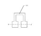
本明細書で開示する発明の具体的な一例は、図1にその画素構造を示すように、ソース線105及びゲイト線104と画素電極107との間に透明導電膜でなる電極パターン106が配置され、該電極パターン106と画素電極107との間で補助容量が形成されていることを特徴とする。
【0020】
【実施例】
〔実施例1〕
図1〜図3に本実施例の構成を示す。図1〜図3に示すのは、透過型の形式を有するアクティブマトリクス型の液晶表示装置の1画素の部分を上面から拡大した状態を示している。
【0021】
図1〜図3は同じものを示している。まず図1を用いてその構成を説明する。図1において、101が薄膜トランジスタの活性層を構成するパターンである。活性層101は結晶性珪素膜で構成されている。
【0022】
102は活性層101の一部であり、ドレイン領域と呼ばれる領域である。103はソース領域と呼ばれる領域である。これらの領域は、Nチャネル型であればN型、Pチャネル型であればP型を有している。
【0023】
104がゲイト線のパターンである。このゲイト線104と活性層101が重なる部分における活性層101の領域がチャネル領域となる。またゲイト線104の活性層101と重なる領域がゲイト電極として機能する。
【0024】
105はソース線である。ソース線105は、コンタクト111を介して、ソース領域103にコンタクトしている。
【0025】
活性層101とゲイト線104との上下方向の位置関係は以下のようになっている。即ち、活性層101上に図示しないゲイト絶縁膜が形成され、さらにその上にゲイト線104が形成されている。
【0026】
そしてゲイト線104上には図示しない層間絶縁膜が形成されており、その上にソース線105が形成されている。
【0027】
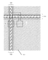
106で示される斜線領域は、容量を形成するためのITOでなる電極パターンである。この電極パターンはアクティブマトリクス領域全体で見ると、格子状のパターンを有している。
【0028】
この容量を形成するためのITOでなる電極パターン106は、適当な一定電位(基準電位)に保たれる構成となっている。具体的には、図示しないアクティブマトリクス回路の端部において、対向基板の電極(この電極は対向電極に接続されている)にコンタクトする構成となっている。こうして、対向電極と同じ電位となるようになっている。
【0029】
補助容量を形成するための電極パターン106の形状は、図1に示されるような形状に限定されるものでない。電極パターン106はITO(または適当な透明導電膜)で構成されているので、その形状に大きな自由度がある。
【0030】
107で示されるのは、画素電極を構成するITOでなるパターンである。このパターン107の縁は、108の破線で示される。即ち、画素電極107の縁は、ソース105及びゲイト線104と一部が重なったものとなっている。
【0031】
画素電極107のパターンを斜線部として強調した図を図2に示す。即ち、図2において、斜線で示される領域が画素電極107である。
【0032】
この画素電極107は、容量を形成するためのITOでなる電極パターン106上に形成された図示しない第2の層間絶縁膜上に形成されている。
【0033】
図1に示すように、画素電極107は、コンタクト110を介して、活性層パターン101のドレイン領域102にコンタクトしている。
【0034】
図1及び図2(特に図2)から明らかなように、画素電極107は、ゲイト線104及びソース線105とその縁が重なるように配置されている。この画素電極107とソース線104及びゲイト線105とが重なった領域が、画素電極の縁周辺を遮光するブラックマトリクスとなる。
【0035】
また、図1に斜線で示される容量を形成するための電極パターン106と図2に斜線で示される画素電極パターン107とは、図3の斜線部109で示される領域において重なる。
【0036】
この2つのITO電極パターンが重なった領域で補助容量が形成される。即ち、液晶と対向電極との間に形成される容量と並列に接続された容量(この容量を補助容量と称する)が形成される。
【0037】
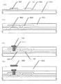
図4以下に図1のA−A’で切った断面の作成工程を示す。また図9以下に対応する断面の作製工程を示す。
【0038】
まず図9(A)に示すように、ガラス基板(または石英基板)901上に下地膜として酸化珪素膜902をスパッタリング法によって3000Åの厚さに成膜する。なお、図4のB−B’で切った断面が図9(A)に対応する。
【0039】
次に図示しない非晶質珪素膜を減圧熱CVD法により、500Åの厚さに成膜する。この非晶質珪素膜は後に薄膜トランジスタの活性層を構成する出発膜となる。
【0040】
図示しない非晶質珪素膜を成膜したら、レーザー光の照射を行う。このレーザー光の照射を行うことにより、非晶質珪素膜は結晶化され、結晶性珪素膜が得られる。
【0041】
次に得られた結晶性珪素膜をパターニングし、図4及び図9(A)の101でそのパターンが示される活性層101を形成する。後の工程において、この活性層中にソース/ドレイン領域やチャネル領域が形成される。
【0042】
こうして図4及び図9(A)に示す状態を得る。次に図9(B)に示すようにゲイト絶縁膜として機能する酸化珪素膜903をプラズマCVD法により、1000Åの厚さに成膜する。(図4には図示せず)
【0043】
次に図5に示すようにゲイト線104を形成する。このゲイト線104はアルミニウムでもって形成する。また図からは明らかでないが、アルミニウムの表面には陽極酸化膜を保護膜して形成する。なお、図9にはゲイト線104は示されていない。(即ち、図9の切断面にはゲイト線は存在しない)
【0044】
ここで、ゲイト線104と活性層101とが重なる活性層の領域がチャネル領域となる。即ち、図5の501と502で示される領域がチャネル領域となる。本実施例の場合、チャネル領域が2つ存在している。この構成は、等価的に2つの薄膜トランジスタが直列に接続された構造となる。
【0045】
このような構成は、1つの薄膜トランジスタに加わる電圧がそれぞれのトランジスタ部に分圧されるので、逆方向リーク電流や劣化の度合いを小さくすることができる。
【0046】
ゲイト線104を形成したら、図5の状態において、不純物のドーピングを行う。ここでは、Nチャネル型の薄膜トランジスタを作製するために、P(リン)元素のドーピングをプラズマドーピング法でもって行う。
【0047】
この不純物のドーピング工程において、ゲイト線104がマスクとなり、自己整合的にソース領域103とドレイン領域102が形成される。また2つのチャネル領域501と502の位置も自己整合的に決定される。
【0048】
不純物のドーピングが終了したら、レーザー光の照射を行うことにより、ドーピングされた元素の活性化とドーピング時の活性層の損傷のアニールとを行う。この活性化はランプ照射や加熱処理によって行ってもよい。
【0049】
ゲイト線104を形成したら、窒化珪素膜904とポリイミド膜905でなる積層膜を形成する。この積層膜は第1の層間絶縁膜として機能する。こうして図9(B)に示す状態を得る。
【0050】
ポリイミド等の樹脂膜を層間絶縁膜として利用した場合、その表面を平坦なものとすることができる。
【0051】
次に図9(C)に示すように、904と905の積層体でなる第1の層間絶縁膜にコンタクトホール111を形成する。そして、図6及び図9(C)に示すようにソース線105を形成する。
【0052】
ソース線105は、コンタクトホール111を介してソース領域103とコンタクトした状態となる。なお、図6のC−C’で切った断面が図9(C)に対応する。
【0053】
次に図9(D)及び図7に示すように、第2の層間絶縁膜として、ポリイミド膜906を形成する。
【0054】
さらにITOでなるパターン(補助容量を形成するためのパターン)106を形成する。ここで、図7のD−D’で切った断面が図9(D)に対応する。
【0055】
次に図8及び図10に示すように、第3の層間絶縁膜としてポリイミド膜907を形成する。さらにITOでなる画素電極107を形成する。
【0056】
ここで前述したように、画素電極107とソース線105(及びゲイト線)とが重なった領域がブラックマトリクスとなる。また、ITO電極106と画素電極107とが重なった領域908が補助容量となる。
【0057】
図10に示されるような断面構造とすることにより、以下のような有意性を得ることができる。
【0058】
(その1)
画素電極107の縁をソース線及びゲイト線と重ねることで、この重なった領域をブラックマトリクスとして機能させることができる。このようにすることにより、開口率を最大限高めることができる。
【0059】
(その2)
図10の908で示されるITOでなるパターン106と画素電極107との間で908で示される補助容量を形成することで、開口率の低下をきたすことなく、必要とする容量値を得ることができる。特に必要とする容量を得るために、画素電極に重ねて形成するITOパターンの自由度を高めることができる。
【0060】
(その3)
図10から明らかなように、補助容量を形成するためのITOパターン106をソース線105より大きな面積を有するパターンとし、また適当な基準電位に保持する。こうすることにより、ITOパターン106を電気的に画素電極107とソース線105とを遮蔽するシールド膜とすることができる。そして、ソース線105と画素電極107との間におけるクロストークを抑制することができる。この効果は、画素電極とゲイト線との間においても同様に得られる。
【0061】
〔実施例2〕
本実施例は、実施例1を変形した構成に関する。実施例1に示した構成は、ソース線及びゲイト線と画素電極とを重ね、その重なった領域をBM(ブラックマトリクス)として機能させている。
【0062】
実施例1の構成は、開口率を最大限大きくする上で有用な構成である。しかし、要求される画質や表示方法によっては、ブラックマトリクスの面積をより大きくした構成が求められる場合もある。
【0063】
本実施例は、このような場合に利用できる構成に関する。図11に本実施例の画素部分の断面を示す。図11は図10に対応するもので、図10と同じ符号は同じ箇所を示す。
【0064】
本実施例においては、チタン膜やクロム膜(また適当な金属膜)でなるブラックマトリクスを構成する膜1102が配置され、その一部とITOでなる画素電極107の縁の部分とが重なる構成となっている。
【0065】
1101は、補助容量の値をさらに大きくするためにブラックマトリクス1102を覆って、それよりさらに大きな面積を有するITOパターンである。この補助容量を形成するためのITOパターンは、その面積を大きくしても開口率を低下させることがない。
【0066】
【発明の効果】
本明細書で開示する発明を採用することで、画素の開口率を下げることなくブラックマトリクスを設けることができる。
【0067】
また、画素の開口率を低下させることなく必要とする補助容量を設けることができる。
【0068】
また、補助容量を形成する透明電極によって、ソース線及びゲイト線と画素電極とのクロストークを抑制する構成とすることができる。
【図面の簡単な説明】
【図1】発明を利用したアクティブマトリクス回路の上面図。
【図2】発明を利用したアクティブマトリクス回路の上面図。
【図3】発明を利用したアクティブマトリクス回路の上面図。
【図4】発明を利用したアクティブマトリクス回路の作製工程上面図。
【図5】発明を利用したアクティブマトリクス回路の作製工程上面図。
【図6】発明を利用したアクティブマトリクス回路の作製工程上面図。
【図7】発明を利用したアクティブマトリクス回路の作製工程上面図。
【図8】発明を利用したアクティブマトリクス回路の作製工程上面図。
【図9】発明を利用したアクティブマトリクス回路の作製工程断面図。
【図10】発明を利用したアクティブマトリクス回路の作製工程断面図。
【図11】発明を利用したアクティブマトリクス回路の作製工程断面図。
【符号の説明】
101 薄膜トランジスタの活性層
102 ドレイン領域
103 ソース領域
104 ゲイト線
105 ソース線
106 補助容量形成用のITO電極
107 画素電極を構成するITO電極
108 画素電極の縁
109 補助容量形成用のITO電極と画素電極を構成するITO電極とが重なる領域
501、502 チャネル領域
111 ソース領域のへのコンタクト部(コンタクトホール)
110 ドレイン領域へのコンタクト部(コンタクトホール)
901 ガラス基板
902 下地膜(酸化珪素膜)
903 ゲイト絶縁膜(酸化珪素膜)
904 第1の層間絶縁膜を構成する窒化珪素膜
905 第1の層間絶縁膜を構成するポリイミド膜
906 第2の層間絶縁膜を構成するポリイミド膜
907 第3の層間絶縁膜を構成するポリイミド膜
908 補助容量の形成部
1101 補助容量を構成するITO電極
1102 ブラックマトリクスを構成する金属電極[0001]
BACKGROUND OF THE INVENTION
The invention disclosed in this specification relates to a structure of a transmissive liquid crystal display device. Or relates to a manufacturing method thereof.
[0002]
[Prior art]
A flat panel display represented by a liquid crystal display device is known. In a transmissive liquid crystal display device having a form in which light is transmitted through a liquid crystal panel and the transmitted light is optically modulated by the liquid crystal panel, a light shielding means called a black matrix is required to clarify the outline of the pixel. ing. Specifically, a configuration is required in which the periphery of the pixel electrode is covered with a light-shielding frame.
[0003]
This black matrix plays an important role particularly when fine moving image display is required.
[0004]
However, the black matrix reduces the effective area of pixels (this ratio is referred to as the aperture ratio), and has the disadvantage of darkening the screen.
[0005]
In recent years, attempts have been made to use flat panel displays in low power consumption portable devices (portable video cameras and portable information terminals).
[0006]
The problem here is the low power consumption characteristic required for portable devices. That is, a configuration for reducing power consumption used for screen display is required.
[0007]
In the case of a transmissive liquid crystal display device, the problem is how to reduce the power consumed by the backlight that emits light from the back side of the liquid crystal panel. In order to reduce the power consumption of the backlight, the brightness of the backlight may be reduced by increasing the aperture ratio of the pixels.
[0008]
On the other hand, in the case of a liquid crystal display device, it is necessary to arrange a capacity called an auxiliary capacity in order to supplement the capacity of the liquid crystal in each pixel. The auxiliary capacitor has a function of holding information (corresponding to the charge amount) written in the pixel electrode rewritten at a predetermined time interval until the next rewrite. If the value of the auxiliary capacitance is small, display flicker and color unevenness (particularly manifested during color display) occur.
[0009]
However, providing an auxiliary capacitor for each pixel causes a reduction in the aperture ratio of the pixel, as in the case of disposing a black matrix.
[0010]
[Problems to be solved by the invention]
As described above, the arrangement of the black matrix or the auxiliary capacitor in order to improve the image quality causes a reduction in the aperture ratio of the pixel. In other words, the decrease in the aperture ratio causes a decrease in image quality.
[0011]
That is, obtaining a clear image display (the effect of the black matrix) and obtaining a bright image (increasing the aperture ratio) are contradictory requirements.
[0012]
Further, it is a contradictory requirement to suppress a flickering feeling of display and to suppress color unevenness (effect of auxiliary capacity) and to obtain a bright image (increase in aperture ratio).
[0013]
An object of the invention disclosed in this specification is to provide a technique for solving the contradictory requirements.
[0014]
[Means for Solving the Problems]
One of the inventions disclosed in this specification is:
An active matrix display device,
An electrode pattern made of a transparent conductive film is disposed between the source and gate lines and the pixel electrode,
A storage capacitor is formed between the electrode pattern and the pixel electrode.
[0015]
Other aspects of the invention are:
An active matrix display device,
An electrode pattern made of a transparent conductive film is disposed between the source and gate lines and the pixel electrode,
The edge of the pixel electrode is disposed overlapping the source and gate lines,
A storage capacitor is formed between the electrode pattern made of the transparent conductive film and the pixel electrode.
[0016]
In the configurations of the two inventions, the electrode pattern made of the transparent conductive film functions as a shield film that electrically shields the source and gate lines and the pixel electrode.
[0017]
Other aspects of the invention are:
An active matrix display device,
An electrode pattern made of a transparent conductive film is disposed so as to cover the source and the gate line.
[0018]
In the above configuration, the electrode pattern made of the transparent conductive film partially overlaps the pixel electrode to form an auxiliary capacitor. The electrode pattern made of a transparent conductive film functions as a shield film that electrically shields the source and gate lines and the pixel electrode.
[0019]
DETAILED DESCRIPTION OF THE INVENTION
As a specific example of the invention disclosed in this specification, an
[0020]
【Example】
[Example 1]
1 to 3 show the configuration of this embodiment. 1 to 3 show a state in which one pixel portion of an active matrix liquid crystal display device having a transmissive type is enlarged from the upper surface.
[0021]
1 to 3 show the same thing. First, the configuration will be described with reference to FIG. In FIG. 1,
[0022]
[0023]
[0024]
[0025]
The vertical positional relationship between the
[0026]
An unillustrated interlayer insulating film is formed on the
[0027]
A hatched area indicated by 106 is an electrode pattern made of ITO for forming a capacitor. This electrode pattern has a lattice pattern when viewed in the entire active matrix region.
[0028]
The
[0029]
The shape of the
[0030]
[0031]
FIG. 2 is a diagram in which the pattern of the
[0032]
The
[0033]
As shown in FIG. 1, the
[0034]
As is clear from FIG. 1 and FIG. 2 (particularly FIG. 2), the
[0035]
In addition, the
[0036]
A storage capacitor is formed in a region where the two ITO electrode patterns overlap. That is, a capacitor connected in parallel with the capacitor formed between the liquid crystal and the counter electrode (this capacitor is referred to as an auxiliary capacitor) is formed.
[0037]
FIG. 4 and subsequent figures show a process of creating a cross section cut along AA ′ in FIG. In addition, a cross-sectional manufacturing process corresponding to FIGS.
[0038]
First, as shown in FIG. 9A, a
[0039]
Next, an amorphous silicon film (not shown) is formed to a thickness of 500 mm by low pressure thermal CVD. This amorphous silicon film later becomes a starting film constituting the active layer of the thin film transistor.
[0040]
When an amorphous silicon film (not shown) is formed, laser light irradiation is performed. By performing this laser light irradiation, the amorphous silicon film is crystallized to obtain a crystalline silicon film.
[0041]
Next, the obtained crystalline silicon film is patterned to form an
[0042]
Thus, the state shown in FIGS. 4 and 9A is obtained. Next, as shown in FIG. 9B, a
[0043]
Next, a
[0044]
Here, a region of the active layer where the
[0045]
In such a configuration, since the voltage applied to one thin film transistor is divided into the respective transistor portions, the reverse leakage current and the degree of deterioration can be reduced.
[0046]
After the
[0047]
In this impurity doping process, the
[0048]
After the impurity doping is completed, laser light irradiation is performed to activate the doped element and anneal the active layer during the doping. This activation may be performed by lamp irradiation or heat treatment.
[0049]
When the
[0050]
When a resin film such as polyimide is used as an interlayer insulating film, its surface can be made flat.
[0051]
Next, as shown in FIG. 9C, a
[0052]
The
[0053]
Next, as shown in FIGS. 9D and 7, a
[0054]
Further, a pattern (pattern for forming an auxiliary capacitor) 106 made of ITO is formed. Here, the cross section taken along the line DD ′ in FIG. 7 corresponds to FIG.
[0055]
Next, as shown in FIGS. 8 and 10, a
[0056]
As described above, the region where the
[0057]
By adopting a cross-sectional structure as shown in FIG. 10, the following significance can be obtained.
[0058]
(Part 1)
By overlapping the edge of the
[0059]
(Part 2)
By forming an auxiliary capacitance indicated by 908 between the
[0060]
(Part 3)
As is apparent from FIG. 10, the
[0061]
[Example 2]
The present embodiment relates to a configuration obtained by modifying the first embodiment. In the configuration shown in the first embodiment, the source and gate lines and the pixel electrode are overlapped with each other, and the overlapped region functions as a BM (black matrix).
[0062]
The configuration of the first embodiment is useful for maximizing the aperture ratio. However, depending on the required image quality and display method, a configuration in which the area of the black matrix is larger may be required.
[0063]
The present embodiment relates to a configuration that can be used in such a case. FIG. 11 shows a cross section of the pixel portion of this embodiment. 11 corresponds to FIG. 10, and the same reference numerals as those in FIG. 10 denote the same parts.
[0064]
In this embodiment, a
[0065]
[0066]
【The invention's effect】
By employing the invention disclosed in this specification, a black matrix can be provided without reducing the aperture ratio of pixels.
[0067]
Further, a necessary auxiliary capacity can be provided without reducing the aperture ratio of the pixel.
[0068]
In addition, the transparent electrode that forms the storage capacitor can be configured to suppress crosstalk between the source line and the gate line and the pixel electrode.
[Brief description of the drawings]
FIG. 1 is a top view of an active matrix circuit using the invention.
FIG. 2 is a top view of an active matrix circuit using the invention.
FIG. 3 is a top view of an active matrix circuit using the invention.
FIG. 4 is a top view of manufacturing steps of an active matrix circuit using the invention.
FIGS. 5A and 5B are top views of manufacturing steps of an active matrix circuit using the invention. FIGS.
FIG. 6 is a top view of a manufacturing process of an active matrix circuit using the invention.
FIG. 7 is a top view of a manufacturing process of an active matrix circuit using the invention.
FIG. 8 is a top view of a manufacturing process of an active matrix circuit using the invention.
9 is a cross-sectional view of a manufacturing process of an active matrix circuit using the invention. FIG.
FIG. 10 is a cross-sectional view of a manufacturing process of an active matrix circuit using the invention.
FIG. 11 is a cross-sectional view of a manufacturing process of an active matrix circuit using the invention.
[Explanation of symbols]
DESCRIPTION OF
110 Contact to drain region (contact hole)
901
903 Gate insulating film (silicon oxide film)
904
Claims (8)
チャネル領域と、ドレイン領域と、ソース領域とを有する活性層と、
前記活性層上に形成されたゲイト絶縁膜と、
前記ゲイト絶縁膜を介して、前記チャネル領域上に重なるように形成されたゲイト線と、
前記ゲイト線上に形成された第1の層間絶縁膜と、
前記第1の層間絶縁膜上に形成され、前記ソース領域に電気的に接続されたソース線と、
前記ソース線上に形成された第2の層間絶縁膜と、
前記第2の層間絶縁膜上であって、前記ソース線及び前記ゲイト線を覆うように形成された透明導電膜でなる電極パターンと、
前記電極パターン上に形成された第3の層間絶縁膜と、
前記第3の層間絶縁膜上であって、前記ドレイン領域に電気的に接続された画素電極とを有し、
前記画素電極の縁が前記ソース線及び前記ゲイト線と重なって、前記ソース線及び前記ゲイト線がブラックマトリクスとして機能し、
前記電極パターンは一定の電位に保たれた格子状のパターンであり、
前記画素電極の縁は前記電極パターンと重なって、補助容量が形成されていることを特徴とする表示装置。An active matrix display device,
An active layer having a channel region, a drain region, and a source region;
A gate insulating film formed on the active layer;
A gate line formed so as to overlap the channel region via the gate insulating film ;
A first interlayer insulating film formed on the gate line;
A source line formed on the first interlayer insulating film and electrically connected to the source region;
A second interlayer insulating film formed on the source line;
An electrode pattern made of a transparent conductive film formed on the second interlayer insulating film so as to cover the source line and the gate line;
A third interlayer insulating film formed on the electrode pattern;
Even on the third interlayer insulating film, have a and electrically connected to the pixel electrode to the drain region,
The edge of the pixel electrode overlaps the source line and the gate line, and the source line and the gate line function as a black matrix,
The electrode pattern is a lattice pattern kept at a constant potential,
A display device , wherein an edge of the pixel electrode overlaps the electrode pattern to form an auxiliary capacitor .
チャネル領域と、ドレイン領域と、ソース領域とを有する活性層と、An active layer having a channel region, a drain region, and a source region;
前記活性層上に形成されたゲイト絶縁膜と、A gate insulating film formed on the active layer;
前記ゲイト絶縁膜を介して、前記チャネル領域上に重なるように形成されたゲイト線と、A gate line formed so as to overlap the channel region via the gate insulating film;
前記ゲイト線上に形成された第1の層間絶縁膜と、A first interlayer insulating film formed on the gate line;
前記第1の層間絶縁膜上に形成され、前記ソース領域に電気的に接続されたソース線と、A source line formed on the first interlayer insulating film and electrically connected to the source region;
前記ソース線上に形成された第2の層間絶縁膜と、A second interlayer insulating film formed on the source line;
前記第2の層間絶縁膜上であって、前記ソース線及び前記ゲイト線を覆うように形成された透明導電膜でなる電極パターンと、An electrode pattern made of a transparent conductive film formed on the second interlayer insulating film so as to cover the source line and the gate line;
前記電極パターン上に形成された第3の層間絶縁膜と、A third interlayer insulating film formed on the electrode pattern;
前記第3の層間絶縁膜上であって、前記ドレイン領域に電気的に接続された画素電極とが、前記基板の一方に設けられ、A pixel electrode on the third interlayer insulating film and electrically connected to the drain region is provided on one of the substrates;
前記基板の他方には、前記画素電極と対向する対向電極と、前記対向電極に電気的に接続された電極とが設けられ、The other side of the substrate is provided with a counter electrode facing the pixel electrode and an electrode electrically connected to the counter electrode,
前記画素電極の縁が前記ソース線及び前記ゲイト線と重なって、前記ソース線及び前記ゲイト線がブラックマトリクスとして機能し、The edge of the pixel electrode overlaps the source line and the gate line, and the source line and the gate line function as a black matrix,
前記電極パターンは格子状のパターンであり、かつ前記他方の基板に設けられた前記電極に電気的に接続されて、前記対向電極と同じ一定の電位に保たれ、The electrode pattern is a lattice pattern and is electrically connected to the electrode provided on the other substrate, and is kept at the same constant potential as the counter electrode,
前記画素電極の縁は前記電極パターンと重なって、補助容量が形成されていることを特徴とする表示装置。A display device, wherein an edge of the pixel electrode overlaps the electrode pattern to form an auxiliary capacitor.
前記活性層と前記ゲイト線は2カ所で重なり、前記活性層には、前記チャネル領域が2つ存在することを特徴とする表示装置。In claim 1 or 2 ,
2. The display device according to claim 1, wherein the active layer and the gate line overlap each other at two locations, and the active layer has two channel regions.
前記電極パターンはITOでなることを特徴とする表示装置。In any one of Claim 1 thru | or 3 ,
The display device, wherein the electrode pattern is made of ITO.
前記第1の層間絶縁膜として樹脂膜が形成されていることを特徴とする表示装置。A display device, wherein a resin film is formed as the first interlayer insulating film.
前記第1の層間絶縁膜は窒化珪素膜とポリイミド膜とでなる積層膜であることを特徴とする表示装置。In any one of Claims 1 thru | or 5 ,
Display device wherein the first interlayer insulating film is a multilayer film made of a silicon nitride film and a polyimide film.
前記第2の層間絶縁膜としてポリイミド膜が形成されていることを特徴とする表示装置。A display device, wherein a polyimide film is formed as the second interlayer insulating film.
前記第3の層間絶縁膜としてポリイミド膜が形成されていることを特徴とする表示装置。A display device, wherein a polyimide film is formed as the third interlayer insulating film.
Priority Applications (12)
| Application Number | Priority Date | Filing Date | Title |
|---|---|---|---|
| JP25381796A JP3634089B2 (en) | 1996-09-04 | 1996-09-04 | Display device |
| KR1019970045637A KR100538181B1 (en) | 1996-09-04 | 1997-09-03 | Active matrix display device, semiconductor device and semiconductor display device |
| US08/922,951 US6115088A (en) | 1996-09-04 | 1997-09-03 | Display device |
| US09/546,636 US6421101B1 (en) | 1996-09-04 | 2000-04-07 | Display device including a transparent electrode pattern covering and extending along gate & source lines |
| US10/196,878 US7046313B2 (en) | 1996-09-04 | 2002-07-15 | Semiconductor device including a source line formed on interlayer insulating film having flattened surface |
| KR1020050008463A KR100653409B1 (en) | 1996-09-04 | 2005-01-31 | A semiconductor device |
| US11/069,982 US7023502B2 (en) | 1996-09-04 | 2005-03-03 | Semiconductor device having light-shielded thin film transistor |
| KR1020050053385A KR100700485B1 (en) | 1996-09-04 | 2005-06-21 | A semiconductor device |
| US11/382,412 US7646022B2 (en) | 1996-09-04 | 2006-05-09 | Display device |
| US12/610,450 US7863618B2 (en) | 1996-09-04 | 2009-11-02 | Display device |
| US12/982,255 US8586985B2 (en) | 1996-09-04 | 2010-12-30 | Display device |
| US13/587,958 US8536577B2 (en) | 1996-09-04 | 2012-08-17 | Display device |
Applications Claiming Priority (1)
| Application Number | Priority Date | Filing Date | Title |
|---|---|---|---|
| JP25381796A JP3634089B2 (en) | 1996-09-04 | 1996-09-04 | Display device |
Publications (2)
| Publication Number | Publication Date |
|---|---|
| JPH1078593A JPH1078593A (en) | 1998-03-24 |
| JP3634089B2 true JP3634089B2 (en) | 2005-03-30 |
Family
ID=17256555
Family Applications (1)
| Application Number | Title | Priority Date | Filing Date |
|---|---|---|---|
| JP25381796A Expired - Fee Related JP3634089B2 (en) | 1996-09-04 | 1996-09-04 | Display device |
Country Status (3)
| Country | Link |
|---|---|
| US (8) | US6115088A (en) |
| JP (1) | JP3634089B2 (en) |
| KR (3) | KR100538181B1 (en) |
Families Citing this family (53)
| Publication number | Priority date | Publication date | Assignee | Title |
|---|---|---|---|---|
| JP3634089B2 (en) * | 1996-09-04 | 2005-03-30 | 株式会社半導体エネルギー研究所 | Display device |
| US6088070A (en) | 1997-01-17 | 2000-07-11 | Semiconductor Energy Laboratory Co., Ltd. | Active matrix liquid crystal with capacitor between light blocking film and pixel connecting electrode |
| JP3784491B2 (en) * | 1997-03-28 | 2006-06-14 | 株式会社半導体エネルギー研究所 | Active matrix display device |
| KR100322965B1 (en) * | 1998-03-27 | 2002-06-20 | 주식회사 현대 디스플레이 테크놀로지 | Method for fabricating liquid crystal display |
| JP3980167B2 (en) * | 1998-04-07 | 2007-09-26 | 株式会社日立製作所 | TFT electrode substrate |
| US6493048B1 (en) * | 1998-10-21 | 2002-12-10 | Samsung Electronics Co., Ltd. | Thin film transistor array panel for a liquid crystal display and a method for manufacturing the same |
| US6617644B1 (en) * | 1998-11-09 | 2003-09-09 | Semiconductor Energy Laboratory Co., Ltd. | Semiconductor device and method of manufacturing the same |
| KR100474003B1 (en) * | 1998-11-27 | 2005-09-16 | 엘지.필립스 엘시디 주식회사 | Liquid crystal display device |
| EP2284605A3 (en) | 1999-02-23 | 2017-10-18 | Semiconductor Energy Laboratory Co, Ltd. | Semiconductor device and fabrication method thereof |
| TW478014B (en) * | 1999-08-31 | 2002-03-01 | Semiconductor Energy Lab | Semiconductor device and method of manufacturing thereof |
| US6646287B1 (en) | 1999-11-19 | 2003-11-11 | Semiconductor Energy Laboratory Co., Ltd. | Semiconductor device with tapered gate and insulating film |
| JP2001228457A (en) * | 1999-12-08 | 2001-08-24 | Sharp Corp | Liquid crystal display device |
| US7023021B2 (en) * | 2000-02-22 | 2006-04-04 | Semiconductor Energy Laboratory Co., Ltd. | Semiconductor device and method of manufacturing the same |
| US6789910B2 (en) | 2000-04-12 | 2004-09-14 | Semiconductor Energy Laboratory, Co., Ltd. | Illumination apparatus |
| JP4689851B2 (en) * | 2001-02-23 | 2011-05-25 | Nec液晶テクノロジー株式会社 | Active matrix liquid crystal display device |
| JP2002258320A (en) * | 2001-02-28 | 2002-09-11 | Nec Corp | Liquid crystal display device |
| KR100620847B1 (en) * | 2001-06-05 | 2006-09-13 | 엘지.필립스 엘시디 주식회사 | Array Substrate of Liquid Crystal Display and Fabricating Method Thereof |
| KR100807582B1 (en) * | 2001-07-30 | 2008-02-28 | 엘지.필립스 엘시디 주식회사 | Storage capacitor and liquid crystal display device having the same |
| WO2003042862A2 (en) * | 2001-11-13 | 2003-05-22 | International Business Machines Corporation | System and method for selecting electronic documents from a physical document and for displaying said electronic documents over said physical document |
| KR20030042221A (en) * | 2001-11-22 | 2003-05-28 | 삼성전자주식회사 | a thin film transistor array panel for a liquid crystal display |
| US7079210B2 (en) * | 2001-11-22 | 2006-07-18 | Samsung Electronics Co., Ltd. | Liquid crystal display and thin film transistor array panel |
| KR100857132B1 (en) * | 2001-12-06 | 2008-09-05 | 엘지디스플레이 주식회사 | liquid crystal display devices and manufacturing method of the same |
| US20030117378A1 (en) | 2001-12-21 | 2003-06-26 | International Business Machines Corporation | Device and system for retrieving and displaying handwritten annotations |
| JP2003207794A (en) * | 2002-01-11 | 2003-07-25 | Sanyo Electric Co Ltd | Active matrix type display device |
| JP4216092B2 (en) * | 2002-03-08 | 2009-01-28 | 株式会社半導体エネルギー研究所 | Liquid crystal display |
| KR100498544B1 (en) * | 2002-11-27 | 2005-07-01 | 엘지.필립스 엘시디 주식회사 | Liquid Crystal Display and fabrication method of thereof |
| US7310779B2 (en) | 2003-06-26 | 2007-12-18 | International Business Machines Corporation | Method for creating and selecting active regions on physical documents |
| KR100527195B1 (en) * | 2003-07-25 | 2005-11-08 | 삼성에스디아이 주식회사 | Flat Panel Display |
| TWI226712B (en) * | 2003-12-05 | 2005-01-11 | Au Optronics Corp | Pixel structure and fabricating method thereof |
| CN100399168C (en) * | 2003-12-16 | 2008-07-02 | 友达光电股份有限公司 | Picture element structure and manufacturing method thereof |
| US7532899B2 (en) | 2004-04-15 | 2009-05-12 | At&T Mobility Ii Llc | System for providing location-based services in a wireless network, such as locating sets of desired locations |
| US7540451B2 (en) * | 2006-09-05 | 2009-06-02 | Se-Kure Controls, Inc. | System for securing a cable to a portable article |
| JP5042662B2 (en) * | 2007-02-21 | 2012-10-03 | 三菱電機株式会社 | Liquid crystal display device and manufacturing method thereof |
| JP2009226115A (en) * | 2008-03-25 | 2009-10-08 | Sri Sports Ltd | Golf ball |
| KR101515382B1 (en) | 2008-08-26 | 2015-04-27 | 삼성디스플레이 주식회사 | Thin film transistor display panel |
| JP5347412B2 (en) * | 2008-10-01 | 2013-11-20 | セイコーエプソン株式会社 | Electro-optical device and electronic apparatus |
| JP5589359B2 (en) * | 2009-01-05 | 2014-09-17 | セイコーエプソン株式会社 | Electro-optical device and electronic apparatus |
| KR101857405B1 (en) | 2009-07-10 | 2018-05-11 | 가부시키가이샤 한도오따이 에네루기 켄큐쇼 | Semiconductor device and method for manufacturing the same |
| KR101778513B1 (en) | 2009-10-09 | 2017-09-15 | 가부시키가이샤 한도오따이 에네루기 켄큐쇼 | Light-emitting display device and electronic device including the same |
| WO2011158424A1 (en) * | 2010-06-15 | 2011-12-22 | シャープ株式会社 | Thin film transistor substrate and liquid crystal display device |
| CN103137616B (en) | 2011-11-25 | 2017-04-26 | 上海天马微电子有限公司 | Thin film transistor (TFT) array substrate and forming method and display panel thereof |
| CN104508549B (en) | 2012-08-03 | 2018-02-06 | 株式会社半导体能源研究所 | Semiconductor device |
| DE102013216824A1 (en) | 2012-08-28 | 2014-03-06 | Semiconductor Energy Laboratory Co., Ltd. | Semiconductor device |
| TWI611511B (en) | 2012-08-31 | 2018-01-11 | 半導體能源研究所股份有限公司 | Semiconductor device |
| US20140063419A1 (en) * | 2012-09-04 | 2014-03-06 | Shenzhen China Star Optoelectronics Technology Co. Ltd. | Display Panel and Liquid Crystal Display Device |
| KR102250010B1 (en) | 2012-09-13 | 2021-05-11 | 가부시키가이샤 한도오따이 에네루기 켄큐쇼 | Semiconductor device |
| KR102459007B1 (en) | 2012-12-25 | 2022-10-27 | 가부시키가이샤 한도오따이 에네루기 켄큐쇼 | Semiconductor device |
| US9905585B2 (en) | 2012-12-25 | 2018-02-27 | Semiconductor Energy Laboratory Co., Ltd. | Semiconductor device comprising capacitor |
| US9231002B2 (en) | 2013-05-03 | 2016-01-05 | Semiconductor Energy Laboratory Co., Ltd. | Display device and electronic device |
| TWI809225B (en) | 2013-05-16 | 2023-07-21 | 日商半導體能源研究所股份有限公司 | Semiconductor device |
| JP6577224B2 (en) | 2015-04-23 | 2019-09-18 | 株式会社ジャパンディスプレイ | Display device |
| CN205789971U (en) * | 2016-05-16 | 2016-12-07 | 京东方科技集团股份有限公司 | Thin-film transistor array base-plate and apply its display device |
| CN112740309B (en) * | 2018-09-21 | 2022-09-06 | 夏普株式会社 | Display device |
Family Cites Families (72)
| Publication number | Priority date | Publication date | Assignee | Title |
|---|---|---|---|---|
| JP3307150B2 (en) | 1995-03-20 | 2002-07-24 | ソニー株式会社 | Active matrix display |
| FR2284984A1 (en) * | 1974-09-13 | 1976-04-09 | Commissariat Energie Atomique | Radiation scanning method - by charge carrier collecting zone of MOS transistor with floating substrate zone potential |
| US4239346A (en) * | 1979-05-23 | 1980-12-16 | Hughes Aircraft Company | Compact liquid crystal display system |
| JPS6045219A (en) * | 1983-08-23 | 1985-03-11 | Toshiba Corp | Active matrix type display device |
| JPS60213062A (en) | 1984-04-09 | 1985-10-25 | Hosiden Electronics Co Ltd | Manufacture of thin-film transistor |
| US4598305A (en) * | 1984-06-18 | 1986-07-01 | Xerox Corporation | Depletion mode thin film semiconductor photodetectors |
| JPS6329924A (en) * | 1986-07-23 | 1988-02-08 | Komatsu Ltd | Manufacture of semiconductor device |
| JP2702117B2 (en) | 1987-01-28 | 1998-01-21 | 日本電気株式会社 | Voice duplex communication device |
| US5327001A (en) | 1987-09-09 | 1994-07-05 | Casio Computer Co., Ltd. | Thin film transistor array having single light shield layer over transistors and gate and drain lines |
| JPH01183628A (en) | 1988-01-18 | 1989-07-21 | Matsushita Electric Ind Co Ltd | Active matrix array |
| JPH0210877A (en) * | 1988-06-29 | 1990-01-16 | Matsushita Electric Ind Co Ltd | Manufacture of optical pattern detector |
| JPH02181419A (en) * | 1989-01-06 | 1990-07-16 | Hitachi Ltd | Laser anneal method |
| US5051570A (en) * | 1989-01-20 | 1991-09-24 | Nec Corporation | Liquid crystal light valve showing an improved display contrast |
| JPH02245742A (en) * | 1989-03-17 | 1990-10-01 | Matsushita Electric Ind Co Ltd | Reflection type liquid crystal display device |
| JPH039562A (en) * | 1989-06-07 | 1991-01-17 | Sharp Corp | Semiconductor device |
| JPH0323671A (en) * | 1989-06-21 | 1991-01-31 | Nippon Sheet Glass Co Ltd | Integration functional device and manufacturing method therefor, and functional module using this device |
| JP2538086B2 (en) * | 1990-01-11 | 1996-09-25 | 松下電器産業株式会社 | Liquid crystal display device and manufacturing method thereof |
| JP2622183B2 (en) * | 1990-04-05 | 1997-06-18 | シャープ株式会社 | Active matrix display device |
| US5162933A (en) * | 1990-05-16 | 1992-11-10 | Nippon Telegraph And Telephone Corporation | Active matrix structure for liquid crystal display elements wherein each of the gate/data lines includes at least a molybdenum-base alloy layer containing 0.5 to 10 wt. % of chromium |
| DE69125886T2 (en) * | 1990-05-29 | 1997-11-20 | Semiconductor Energy Lab | Thin film transistors |
| US5273910A (en) * | 1990-08-08 | 1993-12-28 | Minnesota Mining And Manufacturing Company | Method of making a solid state electromagnetic radiation detector |
| US5221365A (en) * | 1990-10-22 | 1993-06-22 | Sanyo Electric Co., Ltd. | Photovoltaic cell and method of manufacturing polycrystalline semiconductive film |
| JP2772405B2 (en) | 1990-11-22 | 1998-07-02 | 株式会社日立製作所 | Liquid crystal display |
| KR960010723B1 (en) * | 1990-12-20 | 1996-08-07 | 가부시끼가이샤 한도오따이 에네루기 겐큐쇼 | Liquid crystal electro-optical device |
| US5289030A (en) * | 1991-03-06 | 1994-02-22 | Semiconductor Energy Laboratory Co., Ltd. | Semiconductor device with oxide layer |
| JP2625267B2 (en) * | 1991-03-07 | 1997-07-02 | シャープ株式会社 | Active matrix display device |
| JP3277548B2 (en) * | 1991-05-08 | 2002-04-22 | セイコーエプソン株式会社 | Display board |
| US6849872B1 (en) * | 1991-08-26 | 2005-02-01 | Semiconductor Energy Laboratory Co., Ltd. | Thin film transistor |
| KR940004322B1 (en) | 1991-09-05 | 1994-05-19 | 삼성전자 주식회사 | Liquid crystal display devices |
| US5191832A (en) * | 1991-09-05 | 1993-03-09 | Tsay Shih C | Tubular stuffing apparatus |
| JPH05142570A (en) * | 1991-11-20 | 1993-06-11 | Sharp Corp | Active matrix substrate |
| US5317433A (en) * | 1991-12-02 | 1994-05-31 | Canon Kabushiki Kaisha | Image display device with a transistor on one side of insulating layer and liquid crystal on the other side |
| JPH05249478A (en) * | 1991-12-25 | 1993-09-28 | Toshiba Corp | Liquid crystal display device |
| US5459595A (en) * | 1992-02-07 | 1995-10-17 | Sharp Kabushiki Kaisha | Active matrix liquid crystal display |
| US5254480A (en) * | 1992-02-20 | 1993-10-19 | Minnesota Mining And Manufacturing Company | Process for producing a large area solid state radiation detector |
| NL194848C (en) * | 1992-06-01 | 2003-04-03 | Samsung Electronics Co Ltd | Liquid crystal indicator device. |
| US5459596A (en) * | 1992-09-14 | 1995-10-17 | Kabushiki Kaisha Toshiba | Active matrix liquid crystal display with supplemental capacitor line which overlaps signal line |
| JP3127619B2 (en) * | 1992-10-21 | 2001-01-29 | セイコーエプソン株式会社 | Active matrix substrate |
| JP2924506B2 (en) * | 1992-10-27 | 1999-07-26 | 日本電気株式会社 | Pixel structure of active matrix liquid crystal display |
| JP2950061B2 (en) | 1992-11-13 | 1999-09-20 | 日本電気株式会社 | Liquid crystal display device |
| EP0598394A3 (en) * | 1992-11-16 | 1997-07-16 | Tokyo Electron Ltd | Method and apparatus for manufacturing a liquid crystal display substrate, and apparatus and method for evaluating semiconductor crystals. |
| KR960001847B1 (en) | 1992-12-21 | 1996-02-06 | 주식회사유공 | Process for producing ethylene-alpha olefinic copolymer rubbers |
| EP0603866B1 (en) * | 1992-12-25 | 2002-07-24 | Sony Corporation | Active matrix substrate |
| EP0642179B1 (en) * | 1993-03-23 | 1999-02-03 | TDK Corporation | Solid state imaging device and process for production thereof |
| US5719065A (en) * | 1993-10-01 | 1998-02-17 | Semiconductor Energy Laboratory Co., Ltd. | Method for manufacturing semiconductor device with removable spacers |
| JP3298109B2 (en) * | 1994-02-17 | 2002-07-02 | セイコーエプソン株式会社 | Active matrix substrate and color liquid crystal display |
| US5822026A (en) * | 1994-02-17 | 1998-10-13 | Seiko Epson Corporation | Active matrix substrate and color liquid crystal display |
| JPH07302912A (en) | 1994-04-29 | 1995-11-14 | Semiconductor Energy Lab Co Ltd | Semiconductor device |
| CN100477247C (en) | 1994-06-02 | 2009-04-08 | 株式会社半导体能源研究所 | Active matrix display and electrooptical device |
| TW289097B (en) * | 1994-08-24 | 1996-10-21 | Hitachi Ltd | |
| JP3238020B2 (en) | 1994-09-16 | 2001-12-10 | 株式会社東芝 | Method for manufacturing active matrix display device |
| JPH08122768A (en) | 1994-10-19 | 1996-05-17 | Sony Corp | Display device |
| JP3081474B2 (en) * | 1994-11-11 | 2000-08-28 | 三洋電機株式会社 | Liquid crystal display |
| GB9424598D0 (en) * | 1994-12-06 | 1995-01-25 | Philips Electronics Uk Ltd | Semiconductor memory with non-volatile memory transistor |
| KR0169385B1 (en) | 1995-03-10 | 1999-03-20 | 김광호 | Thin film transistor substrate for liquid crystal and its manufacturing method |
| JPH08306926A (en) | 1995-05-07 | 1996-11-22 | Semiconductor Energy Lab Co Ltd | Liquid crystal electrooptical system |
| JPH0926603A (en) * | 1995-05-08 | 1997-01-28 | Semiconductor Energy Lab Co Ltd | Display device |
| US6372534B1 (en) * | 1995-06-06 | 2002-04-16 | Lg. Philips Lcd Co., Ltd | Method of making a TFT array with photo-imageable insulating layer over address lines |
| JP3200552B2 (en) | 1995-10-26 | 2001-08-20 | 株式会社日立製作所 | Active matrix type liquid crystal display |
| KR0158260B1 (en) * | 1995-11-25 | 1998-12-15 | 구자홍 | Matrix array and manufacturing method of active matrix liquid crystal display device |
| TW309633B (en) * | 1995-12-14 | 1997-07-01 | Handotai Energy Kenkyusho Kk | |
| JPH09298305A (en) * | 1996-05-08 | 1997-11-18 | Semiconductor Energy Lab Co Ltd | Thin film transistor and liq. crystal display having such thin film transistor |
| JP3433779B2 (en) | 1996-06-19 | 2003-08-04 | シャープ株式会社 | Active matrix substrate and manufacturing method thereof |
| JP3126661B2 (en) * | 1996-06-25 | 2001-01-22 | 株式会社半導体エネルギー研究所 | Liquid crystal display |
| JPH1039333A (en) * | 1996-07-19 | 1998-02-13 | Sharp Corp | Active matrix type liquid crystal display device and method for correcting its defect |
| KR100209620B1 (en) * | 1996-08-31 | 1999-07-15 | 구자홍 | Liquid crystal display device and its manufacturing method |
| JP3634089B2 (en) * | 1996-09-04 | 2005-03-30 | 株式会社半導体エネルギー研究所 | Display device |
| JP3813280B2 (en) | 1997-01-08 | 2006-08-23 | エルジー フィリップス エルシーディー カンパニー リミテッド | Liquid crystal display device and electronic device |
| JP3784491B2 (en) | 1997-03-28 | 2006-06-14 | 株式会社半導体エネルギー研究所 | Active matrix display device |
| JPH1123671A (en) | 1997-06-30 | 1999-01-29 | Ando Electric Co Ltd | Cooling method of semiconductor testing device |
| CN1139837C (en) * | 1998-10-01 | 2004-02-25 | 三星电子株式会社 | Film transistor array substrate for liquid crystal display and manufacture thereof |
| KR100961847B1 (en) | 2008-02-11 | 2010-06-08 | 이승균 | air compressor |
-
1996
- 1996-09-04 JP JP25381796A patent/JP3634089B2/en not_active Expired - Fee Related
-
1997
- 1997-09-03 US US08/922,951 patent/US6115088A/en not_active Expired - Lifetime
- 1997-09-03 KR KR1019970045637A patent/KR100538181B1/en not_active IP Right Cessation
-
2000
- 2000-04-07 US US09/546,636 patent/US6421101B1/en not_active Expired - Lifetime
-
2002
- 2002-07-15 US US10/196,878 patent/US7046313B2/en not_active Expired - Fee Related
-
2005
- 2005-01-31 KR KR1020050008463A patent/KR100653409B1/en not_active IP Right Cessation
- 2005-03-03 US US11/069,982 patent/US7023502B2/en not_active Expired - Fee Related
- 2005-06-21 KR KR1020050053385A patent/KR100700485B1/en not_active IP Right Cessation
-
2006
- 2006-05-09 US US11/382,412 patent/US7646022B2/en not_active Expired - Fee Related
-
2009
- 2009-11-02 US US12/610,450 patent/US7863618B2/en not_active Expired - Fee Related
-
2010
- 2010-12-30 US US12/982,255 patent/US8586985B2/en not_active Expired - Fee Related
-
2012
- 2012-08-17 US US13/587,958 patent/US8536577B2/en not_active Expired - Fee Related
Also Published As
| Publication number | Publication date |
|---|---|
| US8536577B2 (en) | 2013-09-17 |
| US20060192201A1 (en) | 2006-08-31 |
| US7023502B2 (en) | 2006-04-04 |
| JPH1078593A (en) | 1998-03-24 |
| US6115088A (en) | 2000-09-05 |
| US8586985B2 (en) | 2013-11-19 |
| KR20060086783A (en) | 2006-08-01 |
| KR19980024306A (en) | 1998-07-06 |
| US20120305927A1 (en) | 2012-12-06 |
| KR100700485B1 (en) | 2007-03-28 |
| KR20060087987A (en) | 2006-08-03 |
| US7046313B2 (en) | 2006-05-16 |
| KR100538181B1 (en) | 2006-04-28 |
| US7646022B2 (en) | 2010-01-12 |
| US20110163315A1 (en) | 2011-07-07 |
| US7863618B2 (en) | 2011-01-04 |
| US6421101B1 (en) | 2002-07-16 |
| US20020171780A1 (en) | 2002-11-21 |
| KR100653409B1 (en) | 2006-12-05 |
| US20050151891A1 (en) | 2005-07-14 |
| US20100044714A1 (en) | 2010-02-25 |
Similar Documents
| Publication | Publication Date | Title |
|---|---|---|
| JP3634089B2 (en) | Display device | |
| JP3708637B2 (en) | Liquid crystal display device | |
| US5182620A (en) | Active matrix display device | |
| KR100317729B1 (en) | Display thin film semiconductor device and manufacturing method | |
| US6812912B2 (en) | Active matrix display device with storage capacitor for each pixel | |
| US7642554B2 (en) | Array substrate for liquid crystal display device | |
| KR20100091123A (en) | Display device | |
| WO2012147657A1 (en) | Semiconductor device, active matrix board, and display device | |
| KR19990045356A (en) | Liquid crystal display | |
| JPH04283729A (en) | Active matrix display device | |
| JPH10153793A (en) | Liquid crystal display device | |
| JP3669082B2 (en) | Thin film transistor array for liquid crystal display elements | |
| JP3830213B2 (en) | Substrate provided with switching element, liquid crystal display panel, and electronic apparatus using the same | |
| JP3662350B2 (en) | Display device | |
| JPH10133227A (en) | Liquid crystal display device and its production | |
| JP3892115B2 (en) | Display and device with display | |
| JP4031105B2 (en) | Active matrix type liquid crystal display device | |
| JP2002296619A (en) | Active matrix type display device | |
| JP2002297058A (en) | Active matrix type display device | |
| JP2698503B2 (en) | Active matrix liquid crystal display | |
| KR20010009012A (en) | Method for Forming a Panel of a Liquid Crystal Display Device | |
| JP4411825B2 (en) | Manufacturing method of electro-optical device | |
| JPH07146488A (en) | Liquid crystal display device | |
| JPH05167072A (en) | Thin film transistor | |
| JPH08220558A (en) | Thin film transistor and active matrix type liquid crystal display device using thin film transistor |
Legal Events
| Date | Code | Title | Description |
|---|---|---|---|
| A977 | Report on retrieval |
Free format text: JAPANESE INTERMEDIATE CODE: A971007 Effective date: 20041021 |
|
| A131 | Notification of reasons for refusal |
Free format text: JAPANESE INTERMEDIATE CODE: A131 Effective date: 20041026 |
|
| A521 | Request for written amendment filed |
Free format text: JAPANESE INTERMEDIATE CODE: A523 Effective date: 20041116 |
|
| TRDD | Decision of grant or rejection written | ||
| A01 | Written decision to grant a patent or to grant a registration (utility model) |
Free format text: JAPANESE INTERMEDIATE CODE: A01 Effective date: 20041214 |
|
| A61 | First payment of annual fees (during grant procedure) |
Free format text: JAPANESE INTERMEDIATE CODE: A61 Effective date: 20041222 |
|
| R150 | Certificate of patent or registration of utility model |
Free format text: JAPANESE INTERMEDIATE CODE: R150 |
|
| FPAY | Renewal fee payment (event date is renewal date of database) |
Free format text: PAYMENT UNTIL: 20080107 Year of fee payment: 3 |
|
| FPAY | Renewal fee payment (event date is renewal date of database) |
Free format text: PAYMENT UNTIL: 20090107 Year of fee payment: 4 |
|
| FPAY | Renewal fee payment (event date is renewal date of database) |
Free format text: PAYMENT UNTIL: 20090107 Year of fee payment: 4 |
|
| FPAY | Renewal fee payment (event date is renewal date of database) |
Free format text: PAYMENT UNTIL: 20100107 Year of fee payment: 5 |
|
| FPAY | Renewal fee payment (event date is renewal date of database) |
Free format text: PAYMENT UNTIL: 20100107 Year of fee payment: 5 |
|
| FPAY | Renewal fee payment (event date is renewal date of database) |
Free format text: PAYMENT UNTIL: 20100107 Year of fee payment: 5 |
|
| FPAY | Renewal fee payment (event date is renewal date of database) |
Free format text: PAYMENT UNTIL: 20110107 Year of fee payment: 6 |
|
| FPAY | Renewal fee payment (event date is renewal date of database) |
Free format text: PAYMENT UNTIL: 20110107 Year of fee payment: 6 |
|
| FPAY | Renewal fee payment (event date is renewal date of database) |
Free format text: PAYMENT UNTIL: 20120107 Year of fee payment: 7 |
|
| FPAY | Renewal fee payment (event date is renewal date of database) |
Free format text: PAYMENT UNTIL: 20120107 Year of fee payment: 7 |
|
| FPAY | Renewal fee payment (event date is renewal date of database) |
Free format text: PAYMENT UNTIL: 20130107 Year of fee payment: 8 |
|
| FPAY | Renewal fee payment (event date is renewal date of database) |
Free format text: PAYMENT UNTIL: 20130107 Year of fee payment: 8 |
|
| FPAY | Renewal fee payment (event date is renewal date of database) |
Free format text: PAYMENT UNTIL: 20130107 Year of fee payment: 8 |
|
| FPAY | Renewal fee payment (event date is renewal date of database) |
Free format text: PAYMENT UNTIL: 20140107 Year of fee payment: 9 |
|
| R250 | Receipt of annual fees |
Free format text: JAPANESE INTERMEDIATE CODE: R250 |
|
| R250 | Receipt of annual fees |
Free format text: JAPANESE INTERMEDIATE CODE: R250 |
|
| LAPS | Cancellation because of no payment of annual fees |