JP2017002949A - Vacuum heat insulation material and equipment using the same - Google Patents
Vacuum heat insulation material and equipment using the same Download PDFInfo
- Publication number
- JP2017002949A JP2017002949A JP2015115392A JP2015115392A JP2017002949A JP 2017002949 A JP2017002949 A JP 2017002949A JP 2015115392 A JP2015115392 A JP 2015115392A JP 2015115392 A JP2015115392 A JP 2015115392A JP 2017002949 A JP2017002949 A JP 2017002949A
- Authority
- JP
- Japan
- Prior art keywords
- heat insulating
- vacuum heat
- insulating material
- core material
- stress suppressing
- Prior art date
- Legal status (The legal status is an assumption and is not a legal conclusion. Google has not performed a legal analysis and makes no representation as to the accuracy of the status listed.)
- Withdrawn
Links
Images


Abstract
Description
本発明は真空断熱材及び真空断熱材を適用した機器に関する。 The present invention relates to a vacuum heat insulating material and a device to which the vacuum heat insulating material is applied.
関連する技術として特許文献1が知られている。特許文献1は、内側外被材9に対して第21構成部材4a、第22構成部材4b、第23構成部材4cが滑りやすくするための外被滑りシート10を設けている(0009、図1,2)。また、滑りシート10は、芯材1と外側外被材8の間(0038)に設けたり、複数枚設け得ることを開示している(0039)。
Patent document 1 is known as a related technique. Patent Document 1 is provided with a
特許文献1の滑りシートは、芯材間や、芯材と外被材の間などに設けられる。芯材間に設けると、真空断熱材のリサイクル時に、樹脂を主成分とする滑りシートとガラスを主成分とする芯材の分別が困難となったり手間が増加する。芯材と外被材の間に設けると、シート状の滑りシートでは、芯材の圧縮工程や、芯材の曲げ加工の際に位置ずれすることがある。 The sliding sheet of Patent Document 1 is provided between the core materials or between the core material and the jacket material. If it is provided between the core materials, it becomes difficult to separate the sliding sheet mainly composed of resin and the core material mainly composed of glass during the recycling of the vacuum heat insulating material. If it is provided between the core material and the jacket material, the sheet-like sliding sheet may be displaced during the core material compression process or the core material bending process.
上記課題に鑑みてなされた本発明は、芯材と、該芯材を収納する外被材と、曲がり部と、を有する真空断熱材であって、前記芯材は、繊維水溶液から繊維を取り出してから乾燥させる工程を経て得た繊維シートを複数枚積層して有し、前記芯材を収納する袋状の応力抑制部を設け、前記曲がり部について曲率が大きい面の側に、別の応力抑制部を有することを特徴とする。 The present invention made in view of the above problems is a vacuum heat insulating material having a core material, a jacket material for housing the core material, and a bent portion, and the core material takes out fibers from a fiber aqueous solution. A plurality of fiber sheets obtained through a drying process, and a bag-like stress suppressing portion for storing the core material is provided, and another stress is provided on the side of the curved surface with a large curvature. It has the suppression part.
以下、本発明の実施形態を添付の図面を参照しつつ詳細に説明する。同様の構成には同様の符号を付し、同様の説明は繰り返さない。 Hereinafter, embodiments of the present invention will be described in detail with reference to the accompanying drawings. The same reference numerals are given to the same configurations, and the same description will not be repeated.
<<第一実施形態>>
<冷蔵庫1>
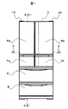
図1は本実施形態の冷蔵庫の正面図であり、図2は図1のA−A断面図を示している。
<< First Embodiment >>
<Refrigerator 1>
FIG. 1 is a front view of the refrigerator of the present embodiment, and FIG. 2 is a cross-sectional view taken along the line AA in FIG.
冷蔵庫1は、上から冷蔵室2、貯氷室3、冷凍室4、野菜室5を有している。各室の前面開口部は、扉6−9で閉塞される。冷蔵室2と製氷室3a及び上段冷凍室3bとの間に仕切断熱壁12を、下段冷凍室4と野菜室5の間に仕切断熱壁14を配置している。仕切断熱壁12、14は厚さ30〜50mm程度の断熱壁で、スチロフォーム、発泡断熱材(硬質ウレタンフォーム)、真空断熱材等、それぞれを単独使用又は複数の断熱材を組み合わせて作られている。各貯蔵室の配置や、冷蔵室扉6a、6b、製氷室扉7a、上段冷凍室扉7b、下段冷凍室扉8、野菜室扉9に関しても回転による開閉、引き出しによる開閉及び扉の分割数等は、特に本実施形態の態様に限定されるものではない。
The refrigerator 1 has the
箱体20は、外箱21と内箱22とを備え、外箱21と内箱22とによって形成される空間に真空断熱材50や硬質ウレタンフォーム等の発泡断熱材23を充填してある。真空断熱材50は、後述する固定部材70、支持部材80等で固定支持されている。
The
<真空断熱材50>
[芯材51]
図3は、真空断熱材50の断面図である。真空断熱材50は、芯材51、芯材51の外周に設けた袋状の応力抑制部52、応力抑制部52の外周に設けた外被材53を有する。芯材51は、繊維集合体のグラスウール繊維を有し、芯材51の中間には吸着剤(不図示)を配している。
<
[Core 51]
FIG. 3 is a cross-sectional view of the vacuum
芯材51は、ガラスカレットを溶融炉で溶かしたガラスを延伸法により紡糸したグラスウールの繊維を用いた繊維シートを複数層重ねたものであり、以下のようにして製造できる。まず、グラスウールの繊維を溶液に入れて撹拌した繊維水溶液から、網状の板で均一になるよう繊維を取出したものを乾燥することで繊維シートを得る。次に、繊維シートを一層以上積層したものを熱風乾燥炉で乾燥する。乾燥温度や時間は、たとえば200℃、5分間にできる。
The
乾燥後に応力抑制部52で芯材51を覆うため、乾燥後の温度が応力抑制部52の融点以下になるようにするか、乾燥後に応力抑制部52の融点以下に冷却する必要がある。乾燥後に応力抑制部52の融点以下に冷却する場合には、冷却時に空気中の水分が吸着しないよう、ドライ雰囲気で冷却するとよい。
In order to cover the
乾燥方式についてもこれに限定されるものではなく、熱プレス方式や、無風乾燥炉等で乾燥してもよい。繊維シートの積層枚数は少ない方が乾燥の効率が良く、グラスウール繊維シートの中央層まで乾燥することができる。グラスウール繊維シートを複数層重ねて乾燥する場合には、芯材51の上部と下部から熱風を通過させて乾燥することが好ましい。
The drying method is not limited to this, and drying may be performed by a hot press method, a windless drying furnace, or the like. The smaller the number of laminated fiber sheets, the better the drying efficiency, and the glass wool fiber sheet can be dried to the center layer. When a plurality of glass wool fiber sheets are stacked and dried, it is preferable that hot air is passed from the upper part and the lower part of the
グラスウールの繊維径は細いほど繊維集合体としたときの空間層である空隙率が高くなることから、熱伝導率の観点からは細い方が好ましい。しかし、グラスウールの繊維径が細いと製造時に繊維が折れやすく、折れた繊維は短いため断熱方向に向きやすく断熱面から熱が伝わりやすくなってしまう。そのため、グラスウールの繊維径は1.0〜10.0μm、平均繊維径は3.0〜5.0μmが好ましい。さらに好ましくは、グラスウールの繊維径は2.0〜8.0μm、平均繊維径は3〜4μmが好ましい。本実施例においては、1.8〜8.8μmのグラスウール繊維を用い、平均繊維径を4.4μmとしている。
[応力抑制部52]
応力抑制部52は、シート状のフィルムを二枚重ね合わせて端部をシールした三方袋であり、内側応力抑制部52aを、内側応力抑制部52aと別体の外側応力抑制部52bに収納している。内側応力抑制部52a及び外側応力抑制部52bは、それぞれ一辺に開口を有している。なお、応力抑制部52a,52bの形状は、筒状でもよい。
The thinner the fiber diameter of the glass wool, the higher the porosity, which is the space layer when the fiber assembly is made, so that the thinner is preferable from the viewpoint of thermal conductivity. However, if the fiber diameter of glass wool is thin, the fiber is likely to be broken at the time of production, and the broken fiber is short, so that it tends to be directed in the heat insulating direction and heat is easily transmitted from the heat insulating surface. Therefore, the fiber diameter of glass wool is preferably 1.0 to 10.0 μm, and the average fiber diameter is preferably 3.0 to 5.0 μm. More preferably, the fiber diameter of glass wool is 2.0 to 8.0 μm, and the average fiber diameter is 3 to 4 μm. In this example, glass wool fibers of 1.8 to 8.8 μm are used, and the average fiber diameter is 4.4 μm.
[Stress suppressing portion 52]
The stress suppressing part 52 is a three-sided bag in which two sheet-like films are overlapped and sealed at the end, and the inner
応力抑制部52は、例えばポリビニルアルコール樹脂フィルム、未延伸タイプのポリエチレン、ポリプロピレン等の樹脂のほか、不織布を採用できる。 As the stress suppressing portion 52, for example, a polyvinyl alcohol resin film, a resin such as unstretched polyethylene or polypropylene, or a non-woven fabric can be used.
不織布は、滑り性を良くするために表面を熱溶着させて繊維の凹凸を少なくすることが好ましい。応力抑制部52を高密度ポリエチレン、外被材53の最内層を低密度ポリエチレンにすると好ましい。
[外被材53]
外被材53はラミネートフィルムを熱溶着により貼り合わせた袋状で構成されている。外被材53は、表面保護層、第一ガスバリヤ層、第二ガスバリヤ層、熱溶着層の4層構成からなる。表面保護層及び熱溶着層は低吸湿性の樹脂フィルムとし、ガスバリヤ層は樹脂フィルムに金属蒸着層を設けたものである。第一ガスバリヤ層は酸素バリヤ性の高い樹脂フィルムに金属蒸着層を設け、第一ガスバリヤ層と第二ガスバリヤ層は金属蒸着層同士が向かい合うように貼り合わせている。
In order to improve the slipperiness of the nonwoven fabric, it is preferable to heat-weld the surface to reduce the unevenness of the fiber. Preferably, the stress suppressing portion 52 is made of high density polyethylene and the innermost layer of the
[Coating material 53]
The
具体的には、表面保護層は、二軸延伸タイプのポリプロピレン、ポリアミド、ポリエチレンテレフタレート等の各フィルム、第一ガスバリヤ層は、アルミニウム蒸着付きの二軸延伸ポリエチレンテレフタレートフィルム、第二ガスバリヤ層は、アルミニウム蒸着付きの二軸延伸エチレンビニルアルコール共重合体樹脂フィルム、アルミニウム蒸着付きの二軸延伸ポリビニルアルコール樹脂フィルム、アルミ箔、熱溶着層は、未延伸タイプのポリエチレン、ポリプロピレン等の各フィルムを採用できる。なお、第一又は第二ガスバリヤ層は、金属箔、或いは樹脂系のフィルムに無機層状化合物、ポリアクリル酸等の樹脂系ガスバリヤコート材、DLC(ダイヤモンドライクカーボン)等によるガスバリヤ膜を設けたものとしてもよい。また、熱溶着層は、酸素バリヤ性の高いポリブチレンテレフタレートフィルム等を用いても良い。 Specifically, the surface protective layer is a biaxially stretched polypropylene, polyamide, polyethylene terephthalate film, the first gas barrier layer is a biaxially stretched polyethylene terephthalate film with aluminum deposition, and the second gas barrier layer is aluminum. For the biaxially stretched ethylene vinyl alcohol copolymer resin film with vapor deposition, the biaxially stretched polyvinyl alcohol resin film with aluminum vapor deposition, the aluminum foil, and the heat welding layer, films such as unstretched polyethylene and polypropylene can be employed. The first or second gas barrier layer is a metal foil or a resin film provided with a gas barrier film made of an inorganic layered compound, a resin gas barrier coating material such as polyacrylic acid, or DLC (diamond-like carbon). Also good. Further, a polybutylene terephthalate film having a high oxygen barrier property or the like may be used for the heat welding layer.
表面保護層及び熱溶着層を低吸湿性にすることで、真空断熱材50を製造する際の真空排気工程において、外被材53が持ち込む水分量を小さくできるため、真空排気効率を向上させて、断熱性能の高性能化が可能になる。尚、各フィルムのラミネート(貼り合せ)は、二液硬化型ウレタン接着剤を介してドライラミネート法によって貼り合わせるのが一般的であるが、接着剤の種類や貼り合わせ方法には特にこれに限定するものではなく、ウェットラミネート法、サーマルラミネート法等の他の方法によるものでも何ら構わない。
[真空引き工程]
上述した乾燥工程後の繊維シートを複数枚積層して芯材51とする。二重にした応力抑制部52の開口から芯材51を収納して、応力抑制部52とともに圧縮する。その後、熱溶着で応力抑制部52の開口をシールすることで、芯材51と応力抑制部52で構成されるコア材を得ることができる。コア材は、圧縮により薄厚になっている。次に、コア材を外被材53に挿入する。薄厚のコア材は、外被材53に容易に挿入することができる。また、外被材53の寸法をコア材に近い寸法にできるため、製造した真空断熱材50のヒートブリッジを低減することができる。
By making the surface protective layer and the heat-welding layer low in hygroscopicity, the amount of moisture brought into the
[Vacuum drawing process]
A plurality of fiber sheets after the drying step described above are laminated to form a
外被材53に挿入したコア材の外周、例えば応力抑制部52を破る等して開口を設け、真空包装することで真空断熱材50を得ることができる。
The vacuum
<曲げ加工>
次に、配置される空間の形状に応じて真空断熱材50を曲げる曲げ加工について説明する。図4は、曲げ加工によって曲がり部60を設けられた真空断熱材50の断面図である。
<Bending process>
Next, the bending process which bends the vacuum
曲げ加工は、不図示の治具で真空断熱材50を固定し、これを折り曲げて曲がり部60を設けて行えるが、溝や凹凸形状を予め芯材51に設けておくと、より容易に真空断熱材50を曲げることができる。
The bending can be performed by fixing the vacuum
真空断熱材50は、芯材51と外被材53の間に応力抑制部52a,52bが位置している。曲がり部60の内周側(曲率の大きい側)に応力抑制部52a,52bが位置するように曲げ加工を行う。すると、応力抑制部52aと応力抑制部52bの接触面同士、外被材53の最内層と応力抑制部52の接触面同士が滑ることにより、芯材51にかかる応力集中を抑制でき、曲げ部60の繊維が折れることを抑制できる。
In the vacuum
芯材51は、繊維シートを厚み方向に複数枚積層したものである。このため、芯材51が曲げられて、応力が大きくなりやすい内周側の繊維に破断が生じても、この破断が厚み方向に伝達することを、芯材51が厚み方向に一枚等の少数枚で構成されている場合に比して、抑制できる。
The
なお、曲がり部60の曲がり角度は特に制限されない。また、屈曲に限らず、湾曲、波形状等としてもよい。
Note that the bending angle of the bending
応力抑制部52を厚くすると、曲がり部60の成形時に生じる芯材への応力を少なくすることができる一方、応力抑制部52、外被材53が厚くなるほど加工が困難になり、作業牲が低下するため、両者のバランスを考慮する必要がある。応力抑制部52の厚さは10μm〜100μmにできるが、好ましくは、20,30,40,50,60,70,80,90μmのうち、一つを下限値に、他の一つを上限値にする。これにより得られた真空断熱材を冷蔵庫の断熱部に貼り付け、より寸法精度の高い真空断熱材を用いることで断熱性能の良い機器を提供することができる。
If the stress suppressing portion 52 is thickened, the stress on the core material generated when the
<リサイクル>
上述のように製造した真空断熱材50は、使用後のリサイクル時にも有効な構成となっている。真空断熱材50の主成分は、芯材51のガラス繊維である。しかし、真空断熱材50を取り付ける機器の多くは、鉄などの金属を主成分としているため、機器のリサイクル時には、これらを分別しなくてはならない。しかし、真空断熱材50の最外周面である外被材53は、機器の一例である冷蔵庫1の外箱21の鉄板面に、例えば接着剤で貼り付けられている。
<Recycling>
The vacuum
本実施形態の真空断熱材50は、芯材51を応力抑制部52で収納している。このため、冷蔵庫1の解体時に真空断熱材50の外被材53を破り応力抑制部52を引き抜くことで、容易に芯材51を取り出すことができる。
In the vacuum
また、応力抑制部52は、芯材51を収納するため、芯材51より寸法が大きい。このため、応力抑制部52のうち、収納時に余った部分を折り曲げて固定した耳を作成しておくと、さらに取り出しやすくなる。なお、外被材53を折り曲げて耳(例えば、図4参照)を作成する際、応力抑制部52の耳を巻き込まずに独立させておくと、応力抑制部52をさらに容易に取り出すことができる。
In addition, the stress suppressing portion 52 is larger in size than the
さらに、応力抑制部52が袋状であるため、樹脂を主成分とする応力抑制部52とガラス等を主成分とする芯材51の分離が容易にできる。また、袋状の応力抑制部52が芯材51の側方への移動を抑制するので、薄厚の芯材51の位置ずれを抑制できる。なお、芯材51は、例えば10層以上の繊維シートを積層して作成できる。
Furthermore, since the stress suppression part 52 is bag-shaped, it is possible to easily separate the stress suppression part 52 mainly composed of resin and the
なお、外被材53の耳が位置する面と反対側に、応力抑制部52a,52bの一面が位置するようにしてある。これにより、曲がり部60の内周側にすべき面の判別が容易になる。この場合、外被材53の耳は曲がり部60の外周側に位置するため、真空断熱材50の内周側を機器に取付けることが容易になる。
It should be noted that one surface of the
<<第二実施形態>>
第二実施形態の構成は、以下の点を除いて第一実施形態と同様にできる。
図5は本実施形態の真空断熱材50の断面図である。本実施形態では、袋状の応力抑制部52を二重構造にする代わりに、応力抑制部52と芯材51との間に、シート状の応力抑制部54を配置している。応力抑制部54は、ポリビニルアルコール樹脂フィルム、未延伸タイプのポリエチレン、ポリプロピレン等の樹脂成分のほか、不織布を採用できる。また、応力抑制シート54は、芯材51の圧縮後に封止すべき開口を設ける必要がないため、アクリル系、ポリアミド系、フッ素系、ビニル系のフィルムを用いることもできる。
<< Second Embodiment >>
The configuration of the second embodiment can be the same as that of the first embodiment except for the following points.
FIG. 5 is a cross-sectional view of the vacuum
応力抑制部54を応力抑制部52と同じ材質にする場合には、応力抑制部52と応力抑制部54を固定することが好ましい。これは、真空包装時に芯材51から真空ポンプに空気が排気されるときに応力抑制部52と応力抑制部54がずれてしまい、応力抑制部54が曲がり部60からずれるおそれを抑制するためである。また、このようにすると、応力抑制部52に応力抑制部54が固定されるため、リサイクル性も向上する。固定法としては、接着剤やテープ、熱溶着等があるが、もっともガスの発生を抑えられるため、熱溶着方式が好ましい。
When the
応力抑制部54は、曲がり部60の内周側(鋭角面側)に位置している。これにより、曲がり部60を形成する際に生じる鋭角部の応力が芯材の一部に集中することを抑制できる。
The
なお、応力抑制部54は、外被材53の耳が位置する面と反対側に位置するようにしてある。これにより、応力抑制部54がどの面に設けられているかの判別が容易になる。この場合、外被材53の耳は曲がり部60の外周側に位置するため、真空断熱材50の内周側を機器に取付けることが容易になる。
In addition, the
<真空断熱材の扉への適用>
次に、真空断熱材50を備える機器の一例である冷蔵庫1について、扉の一例である冷蔵室扉6への真空断熱材50の適用例を説明する。
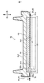
図6は冷蔵室扉6aの分解斜視図、図7は冷蔵室扉6aの縦断面図である。冷蔵室扉6aは、表面に設けられたガラス製の外板6a1と、裏面に設けられた内板6a2と、外板6a1の裏側に配置された真空断熱材50と、発泡断熱材23と、を備えている。真空断熱材50は、外板6a1の裏面に略接触している又は接着等により外板6a1に対する相対移動が抑制されていると、発泡断熱材の充填時の位置ずれを抑制できるため好ましい。
<Application of vacuum insulation to doors>
Next, an application example of the vacuum
6 is an exploded perspective view of the
外板6a1の外側に貼着された両面テープ70は、外板6a1を冷蔵室扉6aの扉枠80に固定している。扉枠は、冷蔵室扉6aの外周部位を形成する樹脂製の枠体である。扉枠80は、外板6a1の右辺部が挿入されて支持される係合溝81aを有する右側の枠部材81と、同様に外板6a1の左辺部、上辺部、下辺部が貼り付けられる両面テープ70が貼着された上側、下側及び左側の枠部材を四角形に連結して形成されている。両面テープ70は、表面及び裏面の両面が貼着可能な細長い帯状の粘着テープである。
The double-
真空断熱材50は冷蔵室扉6aに内設されており、外板6a1の裏面に載置された平板状の部材から成る。真空断熱材50の長さL1(横幅)は、縦断面視して、両面テープ70を貼付するテープ貼付部82aと係合溝81a間との距離L5よりも、長さL3だけ短く形成されている。このため、真空断熱材50は、テープ貼付部82aと係合溝21aとの間に間隔L3を介して、枠部材81,82から中央側に離間されて配置されている。
The vacuum
また、真空断熱材50は、外板6a1側の端部90bの表面側に段差部90aが切欠形成されて、段差部90aと外板6a1との間に隙間Sが形成されている。このため、真空断熱材50は、外板6a1側(表側)の長さL2が、内板6a2側の長さL1よりも小さく形成されている。その結果、発泡断熱材23を充填した際に、発泡断熱材23が隙間Sに入り込んで外板6a1に触れるので、段差部90a及び隙間Sがあることによって、発泡断熱材23と外板6a1とが密着して接着される面積が拡大されている。
Further, in the vacuum
発泡断熱材23は、中央部に真空断熱材50を載置した外板6a1と、外板6a1の外周に取り付けられた扉枠80とで形成された空間に、真空断熱材50を介在させて充填されることによって、空間の内壁面に接着される。このため、発泡断熱材23は、真空断熱材50を覆った状態で外板6a1の裏面に接着されている。
The foam
内板6a2は、冷蔵室扉6aの貯蔵室側に設けられた樹脂製の板部材である。内板6a2は、扉枠20の裏面側の周縁部に固定されている。内板6a2の裏面側の外周部には、冷蔵室扉6aを冷蔵庫本体と密着させて貯蔵室の気密性を確保するためのシール部材(図示省略)が設けられている。
The inner plate 6a2 is a resin plate member provided on the storage chamber side of the
冷蔵室扉6aの作用を組立順に沿って説明する。回動式の冷蔵室扉6aを組み立てる場合は、まず、図6に示すように、4つの枠部材のうち3つそれぞれに両面テープ70を貼り付ける。次に、外板6a1の右端部を枠部材81の係合溝81aに挿入し、外板6a1の上、下、及び左端部を3つの枠部材の両面テープ70に、それぞれ貼り付ける。
The operation of the
続いて、図7に示すように、外板6a1を下側に配置して、その外板6a1の裏面中央部に真空断熱材50を載置して、空間内に発泡断熱材23の材料を充填する。次に、扉枠80の裏面側周縁部に内板6a2を設けて、空間を閉塞する。このようにして冷蔵室扉6aは、組み立てられる。
Subsequently, as shown in FIG. 7, the outer plate 6a1 is disposed on the lower side, the vacuum
このようにして組み立てられた冷蔵室扉6a内の真空断熱材50は、外板6a1に当接している外板6a1側(表面側)の長さL2が、内板6a2側(裏面側)の長さL1よりも小さく形成されている(L1>L2)。真空断熱材50の外板6a1側の表面の端部には、段差部90aが形成されているので、隙間Sが形成されている。このため、発泡断熱材23は、外板6a1の裏面に密着して接着される面積をその段差部90a(隙間S)がある分だけ広げることができるので、発泡断熱材23による外板6a1への接着力を増加させることができる。
The vacuum
このようにすると、接着剤としての機能がある発泡断熱材23は、真空断熱材50を覆った状態で外板6a1に広範囲に亘って接着されるので、特別な固定具及び接着剤を使用せずに又は使用量を抑制して、真空断熱材50を外板6a1にしっかりと固定することができる。その結果、外板6a1は、扉枠80から離脱すること無くしっかりと固定される。
In this case, the foamed
同様にして回動式の冷蔵室扉6bを形成できる。このように形成された回動式の冷蔵室扉6a,6bは、内部の空間の発泡断熱材23の材料を充填し、さらに、発泡断熱材23と外板6a1との間に真空断熱材50が介在されているので、断熱効果を向上させて省エネルギー化を図ることができる。
Similarly, the revolving
1 冷蔵庫 2 冷蔵室 3a 製氷室
3b 上段冷凍室 4 下段冷凍室 5 野菜室
6a 冷蔵室扉 6b 冷蔵室扉 7a 製氷室扉
7b 上段冷凍室扉 8 下段冷凍室扉 9 野菜室扉
10 扉用ヒンジ 11 パッキン
12,14 断熱仕切り 13 仕切り部材
20 箱体 21 外箱 21a 天板
21b 後板 21d 底板 21e 側面
21f 前面 22 内箱 23 断熱材
23a 注入方向 23b 発泡方向 25 注入孔
27 送風機 28 冷却器 30 圧縮機
31 凝縮機 33 発泡ポリスチレン 40 凹部
41 電気部品 42 カバー
50 真空断熱材 51 芯材 52 袋状の応力抑制部
52a 内側応力抑制部 52b 外側応力抑制部
53 外被材
54 シート状の応力抑制部
60 曲がり部
DESCRIPTION OF SYMBOLS 1
12, 14
DESCRIPTION OF
Claims (5)
前記芯材は、繊維水溶液から繊維を取り出してから乾燥させる工程を経て得た繊維シートを複数枚積層して有し、
前記芯材を収納する袋状の応力抑制部を設け、
前記曲がり部について曲率が大きい面の側に、別の応力抑制部を有することを特徴とする真空断熱材。 A vacuum heat insulating material having a core material, a jacket material for storing the core material, and a bent portion,
The core material has a laminate of a plurality of fiber sheets obtained through a process of taking out fibers from an aqueous fiber solution and drying them,
Providing a bag-like stress suppressing portion for storing the core material;
A vacuum heat insulating material having another stress suppressing portion on the side of the surface having a large curvature with respect to the bent portion.
該シート状の応力抑制部を設けた側の面とは反対側の面に向けて、前記外被材を折り曲げた耳部を有することを特徴とする請求項1に記載の真空断熱材。 The another stress suppressing portion is a sheet-like stress suppressing portion,
2. The vacuum heat insulating material according to claim 1, further comprising an ear portion obtained by bending the outer cover material toward a surface opposite to a surface on which the sheet-like stress suppressing portion is provided.
前記扉は、
前記真空断熱材が略接触し、かつ前記真空断熱材の一面側に設けられた外板と、
前記真空断熱材の他面側に設けられた内板と、
発泡断熱材と、を有し、
前記真空断熱材は、
前記外板側の長さを前記内板側の長さより短くして形成した段差部を一面側に有し、
前記発泡断熱材は、
前記真空断熱材の他面側及び前記段差部に位置することを特徴とする機器。 A device comprising a door having the vacuum heat insulating material according to any one of claims 1 to 4,
The door
An outer plate that is substantially in contact with the vacuum heat insulating material and provided on one side of the vacuum heat insulating material;
An inner plate provided on the other surface side of the vacuum heat insulating material;
Foam insulation, and
The vacuum heat insulating material is
A step portion formed by making the length on the outer plate side shorter than the length on the inner plate side on one side,
The foam insulation is
The device is located on the other surface side of the vacuum heat insulating material and the stepped portion.
Priority Applications (1)
| Application Number | Priority Date | Filing Date | Title |
|---|---|---|---|
| JP2015115392A JP2017002949A (en) | 2015-06-08 | 2015-06-08 | Vacuum heat insulation material and equipment using the same |
Applications Claiming Priority (1)
| Application Number | Priority Date | Filing Date | Title |
|---|---|---|---|
| JP2015115392A JP2017002949A (en) | 2015-06-08 | 2015-06-08 | Vacuum heat insulation material and equipment using the same |
Publications (1)
| Publication Number | Publication Date |
|---|---|
| JP2017002949A true JP2017002949A (en) | 2017-01-05 |
Family
ID=57753968
Family Applications (1)
| Application Number | Title | Priority Date | Filing Date |
|---|---|---|---|
| JP2015115392A Withdrawn JP2017002949A (en) | 2015-06-08 | 2015-06-08 | Vacuum heat insulation material and equipment using the same |
Country Status (1)
| Country | Link |
|---|---|
| JP (1) | JP2017002949A (en) |
Cited By (2)
| Publication number | Priority date | Publication date | Assignee | Title |
|---|---|---|---|---|
| CN109813034A (en) * | 2017-11-20 | 2019-05-28 | 东芝生活电器株式会社 | The manufacturing method of vacuum insulation part and vacuum insulation part |
| JP2020016305A (en) * | 2018-07-26 | 2020-01-30 | 大日本印刷株式会社 | Outer packaging material for vacuum heat insulation material, vacuum heat insulation material and article with vacuum heat insulation material |
Citations (11)
| Publication number | Priority date | Publication date | Assignee | Title |
|---|---|---|---|---|
| JPH10205991A (en) * | 1997-01-22 | 1998-08-04 | Sanyo Electric Co Ltd | Thermal insulation box of cooling refrigerator |
| JP2000320958A (en) * | 1999-05-11 | 2000-11-24 | Mitsubishi Electric Corp | Vacuum heat insulating body and heat insulating structural body |
| JP2007009928A (en) * | 2005-06-28 | 2007-01-18 | Hitachi Appliances Inc | Vacuum heat insulating material, its manufacturing method, and refrigerator |
| JP2007056972A (en) * | 2005-08-24 | 2007-03-08 | Hitachi Appliances Inc | Vacuum heat insulating material and refrigerator using the same |
| JP2010096293A (en) * | 2008-10-17 | 2010-04-30 | Mitsubishi Electric Corp | Vacuum heat insulating material |
| JP2011002033A (en) * | 2009-06-18 | 2011-01-06 | Hitachi Appliances Inc | Vacuum heat insulating material, and heat insulating box and refrigerator using the same |
| JP2011149501A (en) * | 2010-01-22 | 2011-08-04 | Hitachi Appliances Inc | Vacuum heat insulating material and refrigerator using the same |
| JP2011196392A (en) * | 2010-03-17 | 2011-10-06 | Mitsubishi Electric Corp | Vacuum heat insulation material and method for producing the same |
| JP2012163138A (en) * | 2011-02-04 | 2012-08-30 | Mitsubishi Electric Corp | Vacuum thermal insulation material, and thermal insulation box |
| JP2013002485A (en) * | 2011-06-14 | 2013-01-07 | Hitachi Appliances Inc | Vacuum thermal insulation material, and refrigerator using the same |
| JP2014051993A (en) * | 2010-10-18 | 2014-03-20 | Mitsubishi Electric Corp | Vacuum heat insulation material and method for manufacturing the same |
-
2015
- 2015-06-08 JP JP2015115392A patent/JP2017002949A/en not_active Withdrawn
Patent Citations (11)
| Publication number | Priority date | Publication date | Assignee | Title |
|---|---|---|---|---|
| JPH10205991A (en) * | 1997-01-22 | 1998-08-04 | Sanyo Electric Co Ltd | Thermal insulation box of cooling refrigerator |
| JP2000320958A (en) * | 1999-05-11 | 2000-11-24 | Mitsubishi Electric Corp | Vacuum heat insulating body and heat insulating structural body |
| JP2007009928A (en) * | 2005-06-28 | 2007-01-18 | Hitachi Appliances Inc | Vacuum heat insulating material, its manufacturing method, and refrigerator |
| JP2007056972A (en) * | 2005-08-24 | 2007-03-08 | Hitachi Appliances Inc | Vacuum heat insulating material and refrigerator using the same |
| JP2010096293A (en) * | 2008-10-17 | 2010-04-30 | Mitsubishi Electric Corp | Vacuum heat insulating material |
| JP2011002033A (en) * | 2009-06-18 | 2011-01-06 | Hitachi Appliances Inc | Vacuum heat insulating material, and heat insulating box and refrigerator using the same |
| JP2011149501A (en) * | 2010-01-22 | 2011-08-04 | Hitachi Appliances Inc | Vacuum heat insulating material and refrigerator using the same |
| JP2011196392A (en) * | 2010-03-17 | 2011-10-06 | Mitsubishi Electric Corp | Vacuum heat insulation material and method for producing the same |
| JP2014051993A (en) * | 2010-10-18 | 2014-03-20 | Mitsubishi Electric Corp | Vacuum heat insulation material and method for manufacturing the same |
| JP2012163138A (en) * | 2011-02-04 | 2012-08-30 | Mitsubishi Electric Corp | Vacuum thermal insulation material, and thermal insulation box |
| JP2013002485A (en) * | 2011-06-14 | 2013-01-07 | Hitachi Appliances Inc | Vacuum thermal insulation material, and refrigerator using the same |
Cited By (2)
| Publication number | Priority date | Publication date | Assignee | Title |
|---|---|---|---|---|
| CN109813034A (en) * | 2017-11-20 | 2019-05-28 | 东芝生活电器株式会社 | The manufacturing method of vacuum insulation part and vacuum insulation part |
| JP2020016305A (en) * | 2018-07-26 | 2020-01-30 | 大日本印刷株式会社 | Outer packaging material for vacuum heat insulation material, vacuum heat insulation material and article with vacuum heat insulation material |
Similar Documents
| Publication | Publication Date | Title |
|---|---|---|
| JP5492685B2 (en) | Vacuum heat insulating material and refrigerator using the same | |
| JP2013088036A (en) | Thermal insulation box, refrigerator, and storage type water heater | |
| JP2009228917A (en) | Refrigerator | |
| JP2013002484A (en) | Vacuum thermal insulation material and refrigerator using the same | |
| JP2016080281A (en) | Heat insulation box body and heat insulation door | |
| JP2011099566A (en) | Vacuum heat insulating panel and refrigerator | |
| JP2011153721A (en) | Refrigerator | |
| JP2012063021A (en) | Vacuum heat insulating material and refrigerator using the same | |
| JP2009024921A (en) | Refrigerator | |
| JP2012225389A (en) | Method of manufacturing vacuum heat insulator, vacuum heat insulator, and refrigerator equipped with the same | |
| JP2017002949A (en) | Vacuum heat insulation material and equipment using the same | |
| JP2013053722A (en) | Vacuum heat insulating material and heat insulating apparatus using the same | |
| JP2001165389A (en) | Insulated box body | |
| JP2013024440A (en) | Refrigerator | |
| JP7139480B2 (en) | refrigerator | |
| WO2014122939A1 (en) | Insulation panel | |
| JP6382596B2 (en) | refrigerator | |
| JP5401422B2 (en) | Vacuum heat insulating material and refrigerator using the same | |
| JP6486079B2 (en) | Method for maintaining heat insulation performance of vacuum insulation panel and method for maintaining heat insulation performance of refrigerator | |
| JP2013002580A (en) | Vacuum thermal insulation material and refrigerator using the same | |
| JP2012229849A (en) | Refrigerator and freezer | |
| JP2012026622A (en) | Vacuum heat insulation material and refrigerator using the same | |
| JP2015001290A (en) | Vacuum heat insulation material and refrigerator | |
| JP2016089962A (en) | Vacuum heat insulation material and refrigerator using vacuum heat insulation material | |
| JP2015200361A (en) | Vacuum heat insulation material and refrigerator using the same |
Legal Events
| Date | Code | Title | Description |
|---|---|---|---|
| A521 | Request for written amendment filed |
Free format text: JAPANESE INTERMEDIATE CODE: A523 Effective date: 20150610 |
|
| RD04 | Notification of resignation of power of attorney |
Free format text: JAPANESE INTERMEDIATE CODE: A7424 Effective date: 20170119 |
|
| RD04 | Notification of resignation of power of attorney |
Free format text: JAPANESE INTERMEDIATE CODE: A7424 Effective date: 20170125 |
|
| A621 | Written request for application examination |
Free format text: JAPANESE INTERMEDIATE CODE: A621 Effective date: 20180213 |
|
| A521 | Request for written amendment filed |
Free format text: JAPANESE INTERMEDIATE CODE: A523 Effective date: 20180214 |
|
| A977 | Report on retrieval |
Free format text: JAPANESE INTERMEDIATE CODE: A971007 Effective date: 20181122 |
|
| A131 | Notification of reasons for refusal |
Free format text: JAPANESE INTERMEDIATE CODE: A131 Effective date: 20190108 |
|
| A521 | Request for written amendment filed |
Free format text: JAPANESE INTERMEDIATE CODE: A523 Effective date: 20190227 |
|
| A131 | Notification of reasons for refusal |
Free format text: JAPANESE INTERMEDIATE CODE: A131 Effective date: 20190604 |
|
| A761 | Written withdrawal of application |
Free format text: JAPANESE INTERMEDIATE CODE: A761 Effective date: 20190717 |