JP2012207570A - バルブタイミング調整装置 - Google Patents
バルブタイミング調整装置 Download PDFInfo
- Publication number
- JP2012207570A JP2012207570A JP2011073212A JP2011073212A JP2012207570A JP 2012207570 A JP2012207570 A JP 2012207570A JP 2011073212 A JP2011073212 A JP 2011073212A JP 2011073212 A JP2011073212 A JP 2011073212A JP 2012207570 A JP2012207570 A JP 2012207570A
- Authority
- JP
- Japan
- Prior art keywords
- valve timing
- sprocket
- sprocket member
- rotational
- radial direction
- Prior art date
- Legal status (The legal status is an assumption and is not a legal conclusion. Google has not performed a legal analysis and makes no representation as to the accuracy of the status listed.)
- Granted
Links
Images


Classifications
-
- F—MECHANICAL ENGINEERING; LIGHTING; HEATING; WEAPONS; BLASTING
- F01—MACHINES OR ENGINES IN GENERAL; ENGINE PLANTS IN GENERAL; STEAM ENGINES
- F01L—CYCLICALLY OPERATING VALVES FOR MACHINES OR ENGINES
- F01L1/00—Valve-gear or valve arrangements, e.g. lift-valve gear
- F01L1/34—Valve-gear or valve arrangements, e.g. lift-valve gear characterised by the provision of means for changing the timing of the valves without changing the duration of opening and without affecting the magnitude of the valve lift
- F01L1/344—Valve-gear or valve arrangements, e.g. lift-valve gear characterised by the provision of means for changing the timing of the valves without changing the duration of opening and without affecting the magnitude of the valve lift changing the angular relationship between crankshaft and camshaft, e.g. using helicoidal gear
- F01L1/3442—Valve-gear or valve arrangements, e.g. lift-valve gear characterised by the provision of means for changing the timing of the valves without changing the duration of opening and without affecting the magnitude of the valve lift changing the angular relationship between crankshaft and camshaft, e.g. using helicoidal gear using hydraulic chambers with variable volume to transmit the rotating force
-
- F—MECHANICAL ENGINEERING; LIGHTING; HEATING; WEAPONS; BLASTING
- F01—MACHINES OR ENGINES IN GENERAL; ENGINE PLANTS IN GENERAL; STEAM ENGINES
- F01L—CYCLICALLY OPERATING VALVES FOR MACHINES OR ENGINES
- F01L1/00—Valve-gear or valve arrangements, e.g. lift-valve gear
- F01L1/02—Valve drive
- F01L1/022—Chain drive
-
- F—MECHANICAL ENGINEERING; LIGHTING; HEATING; WEAPONS; BLASTING
- F01—MACHINES OR ENGINES IN GENERAL; ENGINE PLANTS IN GENERAL; STEAM ENGINES
- F01L—CYCLICALLY OPERATING VALVES FOR MACHINES OR ENGINES
- F01L2303/00—Manufacturing of components used in valve arrangements
Abstract
【解決手段】
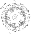
駆動回転体10は、クランク軸との間においてタイミングチェーン3が複数のスプロケット歯132に掛け渡されることにより、カム軸2を駆動するための機関トルクが回転周方向に伝達されるスプロケット部材13、並びにスプロケット部材13と一体に回転する中空状のハウジング15を有する。従動回転体20は、ハウジング15内において回転周方向に区画した作動室30a〜30jに対する作動油の入出により、クランク軸に対するカム軸2の回転位相を変化させる。これら回転体10,20を備える構成においてハウジング15は、同軸上に設けられるカム軸2により回転径方向の内側から軸受される筒状のジャーナル部140と、ジャーナル部140から回転径方向の外側へ離間して設けられ、スプロケット部材13が固定される固定部141とを、有する。
【選択図】図1
Description
内燃機関のクランク軸と連動して回転する駆動回転体であって、クランク軸との間において環状のトルク伝達部材が複数のスプロケット歯に掛け渡されることにより、内燃機関のカム軸を駆動するための機関トルクが回転周方向に伝達されるスプロケット部材、並びにスプロケット部材と一体に回転する中空状のハウジングを有する駆動回転体と、カム軸と連動して回転する従動回転体であって、ハウジング内において回転周方向に区画した作動室に対する作動液の入出により、クランク軸に対するカム軸の回転位相を変化させる従動回転体とを、備え、機関トルクの伝達によりカム軸が開閉する動弁のバルブタイミングを、回転位相の変化により調整するバルブタイミング調整装置において、ハウジングは、同軸上に設けられるカム軸及び従動回転体の少なくとも一方により、回転径方向の内側から軸受される筒状のジャーナル部と、ジャーナル部から回転径方向の外側へ離間して設けられ、スプロケット部材が固定される固定部とを、有することを特徴とする。
図1は、本発明の第一実施形態によるバルブタイミング調整装置1を、車両の内燃機関に適用した例を示している。装置1は、内燃機関においてカム軸2を駆動するための機関トルクをクランク軸(図示しない)から伝達する伝達系に設置され、当該カム軸2が開閉する「動弁」としての吸気弁のバルブタイミングを調整する。具体的に装置1は、クランク軸に対するカム軸2の回転位相を機関位相として変化させることでバルブタイミングを調整する構成として、共通の回転軸線まわりに回転する駆動回転体10及び従動回転体20を、備えている。
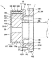
図5に示すように、本発明の第二実施形態において従動回転体2020の回転軸2200は、駆動回転体10の結合部材14のうちジャーナル部140に同軸上に嵌入することで、当該ジャーナル部140を回転径方向の内側から相対回転可能に軸受している。ここで、図5に示すように、回転軸2200のみによりジャーナル部140を軸受してもよいし、図6に変形例を示すように、回転軸2200とカム軸2との共同によりジャーナル部140を軸受してよい。
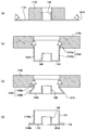
図7に示すように、本発明の第三実施形態において駆動回転体3010のスプロケット部材3013のうち筒部3134は、歯車部131の回転径方向の内側に回転軸方向の全体が重なる状態で、当該歯車部131と同軸上に設けられている。この筒部3134は、第一実施形態で説明した位置決めキー134aを有しておらず、駆動回転体3010の結合部材14のうち固定部141に対して、回転周方向の全域で外嵌されている。こうした外嵌形態により筒部3134には、固定部141が圧入状態で、且つ回転周方向に沿って嵌合している。
以上、本発明の複数の実施形態について説明したが、本発明は、それらの実施形態に限定して解釈されるものではなく、本発明の要旨を逸脱しない範囲内において種々の実施形態及び組み合わせに適用することができる。
Claims (7)
- 内燃機関のクランク軸と連動して回転する駆動回転体であって、前記クランク軸との間において環状のトルク伝達部材が複数のスプロケット歯に掛け渡されることにより、前記内燃機関のカム軸を駆動するための機関トルクが回転周方向に伝達されるスプロケット部材、並びに前記スプロケット部材と一体に回転する中空状のハウジングを有する駆動回転体と、
前記カム軸と連動して回転する従動回転体であって、前記ハウジング内において回転周方向に区画した作動室に対する作動液の入出により、前記クランク軸に対する前記カム軸の回転位相を変化させる従動回転体とを、
備え、前記機関トルクの伝達により前記カム軸が開閉する動弁のバルブタイミングを、前記回転位相の変化により調整するバルブタイミング調整装置において、
前記ハウジングは、
同軸上に設けられる前記カム軸及び前記従動回転体の少なくとも一方により、回転径方向の内側から軸受される筒状のジャーナル部と、
前記ジャーナル部から回転径方向の外側へ離間して設けられ、前記スプロケット部材が固定される固定部とを、
有することを特徴とするバルブタイミング調整装置。 - 前記スプロケット部材は、前記ジャーナル部から回転径方向の外側へ離間して同軸上に設けられる筒部を、有し、
前記固定部は、前記ジャーナル部と同軸上の筒状に形成され、回転周方向に沿って前記筒部と嵌合することにより、前記スプロケット部材と固定されることを特徴とする請求項1に記載のバルブタイミング調整装置。 - 前記筒部は、前記固定部に対して外嵌されることを特徴とする請求項2に記載のバルブタイミング調整装置。
- 前記固定部と前記筒部とは、圧入状態で嵌合することを特徴とする請求項2又は3に記載のバルブタイミング調整装置。
- 前記筒部は、前記スプロケット部材において前記スプロケット歯を形成する歯車部に対して、回転径方向の内側から回転軸方向にずれて設けられることを特徴とする請求項2〜4のいずれか一項に記載のバルブタイミング調整装置。
- 前記筒部は、前記スプロケット部材において前記スプロケット歯を形成する歯車部に対して回転径方向の内側に設けられ、且つ前記固定部に対して回転周方向の全域で嵌合することを特徴とする請求項2〜4のいずれか一項に記載のバルブタイミング調整装置。
- 回転軸方向において前記従動回転体は、前記ハウジングと接触し且つ前記スプロケット部材から離間することを特徴とする請求項1〜6のいずれか一項に記載のバルブタイミング調整装置。
Priority Applications (3)
| Application Number | Priority Date | Filing Date | Title |
|---|---|---|---|
| JP2011073212A JP5360111B2 (ja) | 2011-03-29 | 2011-03-29 | バルブタイミング調整装置 |
| DE102012205028A DE102012205028A1 (de) | 2011-03-29 | 2012-03-28 | Ventilsteuerzeitsteuervorrichtung |
| CN201210088757.1A CN102733880B (zh) | 2011-03-29 | 2012-03-29 | 阀定时控制装置 |
Applications Claiming Priority (1)
| Application Number | Priority Date | Filing Date | Title |
|---|---|---|---|
| JP2011073212A JP5360111B2 (ja) | 2011-03-29 | 2011-03-29 | バルブタイミング調整装置 |
Publications (2)
| Publication Number | Publication Date |
|---|---|
| JP2012207570A true JP2012207570A (ja) | 2012-10-25 |
| JP5360111B2 JP5360111B2 (ja) | 2013-12-04 |
Family
ID=46990085
Family Applications (1)
| Application Number | Title | Priority Date | Filing Date |
|---|---|---|---|
| JP2011073212A Expired - Fee Related JP5360111B2 (ja) | 2011-03-29 | 2011-03-29 | バルブタイミング調整装置 |
Country Status (3)
| Country | Link |
|---|---|
| JP (1) | JP5360111B2 (ja) |
| CN (1) | CN102733880B (ja) |
| DE (1) | DE102012205028A1 (ja) |
Cited By (2)
| Publication number | Priority date | Publication date | Assignee | Title |
|---|---|---|---|---|
| JP2013209977A (ja) * | 2012-03-02 | 2013-10-10 | Aisin Seiki Co Ltd | 弁開閉時期制御装置 |
| JP2013209976A (ja) * | 2012-03-02 | 2013-10-10 | Aisin Seiki Co Ltd | 弁開閉時期制御装置 |
Families Citing this family (3)
| Publication number | Priority date | Publication date | Assignee | Title |
|---|---|---|---|---|
| US8915222B2 (en) * | 2012-03-02 | 2014-12-23 | Aisin Seiki Kabushiki Kaisha | Variable valve timing control apparatus |
| CN105927308A (zh) * | 2016-05-31 | 2016-09-07 | 绵阳富临精工机械股份有限公司 | 一种皮带式凸轮相位器 |
| DE102017122425A1 (de) * | 2017-09-27 | 2019-03-28 | ECO Holding 1 GmbH | Bausatz mit einem Nockenwellenversteller |
Citations (12)
| Publication number | Priority date | Publication date | Assignee | Title |
|---|---|---|---|---|
| JPH08121124A (ja) * | 1994-05-13 | 1996-05-14 | Nippondenso Co Ltd | 内燃機関用バルブタイミング調整装置 |
| JPH1018815A (ja) * | 1996-07-03 | 1998-01-20 | Denso Corp | 内燃機関用バルブタイミング調整装置 |
| JPH112109A (ja) * | 1997-06-13 | 1999-01-06 | Denso Corp | 内燃機関用バルブタイミング調整装置 |
| JP2000045723A (ja) * | 1998-07-31 | 2000-02-15 | Aisin Seiki Co Ltd | 内燃機関の動弁装置 |
| JP2001050019A (ja) * | 1999-08-11 | 2001-02-23 | Unisia Jecs Corp | 内燃機関のバルブタイミング制御装置 |
| JP2002256824A (ja) * | 2001-02-27 | 2002-09-11 | Ntn Corp | エンジンのバルブタイミング調整装置 |
| JP2004239272A (ja) * | 2004-05-26 | 2004-08-26 | Hitachi Unisia Automotive Ltd | 内燃機関のバルブタイミング制御装置 |
| JP2005083363A (ja) * | 2003-09-11 | 2005-03-31 | Denso Corp | バルブタイミング調整装置 |
| JP2005180433A (ja) * | 2003-12-16 | 2005-07-07 | Ina Schaeffler Kg | 内燃機関用の、クランク軸に対するカム軸の回転角度を調節するためのハイドロリック式の装置 |
| JP2005325758A (ja) * | 2004-05-13 | 2005-11-24 | Denso Corp | バルブタイミング調整装置 |
| JP4247624B2 (ja) * | 2004-12-28 | 2009-04-02 | 株式会社デンソー | バルブタイミング調整装置 |
| JP2010174660A (ja) * | 2009-01-27 | 2010-08-12 | Honda Motor Co Ltd | 可変バルブタイミング装置 |
-
2011
- 2011-03-29 JP JP2011073212A patent/JP5360111B2/ja not_active Expired - Fee Related
-
2012
- 2012-03-28 DE DE102012205028A patent/DE102012205028A1/de not_active Withdrawn
- 2012-03-29 CN CN201210088757.1A patent/CN102733880B/zh not_active Expired - Fee Related
Patent Citations (12)
| Publication number | Priority date | Publication date | Assignee | Title |
|---|---|---|---|---|
| JPH08121124A (ja) * | 1994-05-13 | 1996-05-14 | Nippondenso Co Ltd | 内燃機関用バルブタイミング調整装置 |
| JPH1018815A (ja) * | 1996-07-03 | 1998-01-20 | Denso Corp | 内燃機関用バルブタイミング調整装置 |
| JPH112109A (ja) * | 1997-06-13 | 1999-01-06 | Denso Corp | 内燃機関用バルブタイミング調整装置 |
| JP2000045723A (ja) * | 1998-07-31 | 2000-02-15 | Aisin Seiki Co Ltd | 内燃機関の動弁装置 |
| JP2001050019A (ja) * | 1999-08-11 | 2001-02-23 | Unisia Jecs Corp | 内燃機関のバルブタイミング制御装置 |
| JP2002256824A (ja) * | 2001-02-27 | 2002-09-11 | Ntn Corp | エンジンのバルブタイミング調整装置 |
| JP2005083363A (ja) * | 2003-09-11 | 2005-03-31 | Denso Corp | バルブタイミング調整装置 |
| JP2005180433A (ja) * | 2003-12-16 | 2005-07-07 | Ina Schaeffler Kg | 内燃機関用の、クランク軸に対するカム軸の回転角度を調節するためのハイドロリック式の装置 |
| JP2005325758A (ja) * | 2004-05-13 | 2005-11-24 | Denso Corp | バルブタイミング調整装置 |
| JP2004239272A (ja) * | 2004-05-26 | 2004-08-26 | Hitachi Unisia Automotive Ltd | 内燃機関のバルブタイミング制御装置 |
| JP4247624B2 (ja) * | 2004-12-28 | 2009-04-02 | 株式会社デンソー | バルブタイミング調整装置 |
| JP2010174660A (ja) * | 2009-01-27 | 2010-08-12 | Honda Motor Co Ltd | 可変バルブタイミング装置 |
Cited By (3)
| Publication number | Priority date | Publication date | Assignee | Title |
|---|---|---|---|---|
| JP2013209977A (ja) * | 2012-03-02 | 2013-10-10 | Aisin Seiki Co Ltd | 弁開閉時期制御装置 |
| JP2013209976A (ja) * | 2012-03-02 | 2013-10-10 | Aisin Seiki Co Ltd | 弁開閉時期制御装置 |
| JP2017101682A (ja) * | 2012-03-02 | 2017-06-08 | アイシン精機株式会社 | 弁開閉時期制御装置 |
Also Published As
| Publication number | Publication date |
|---|---|
| CN102733880B (zh) | 2014-09-24 |
| JP5360111B2 (ja) | 2013-12-04 |
| CN102733880A (zh) | 2012-10-17 |
| DE102012205028A1 (de) | 2012-10-31 |
Similar Documents
| Publication | Publication Date | Title |
|---|---|---|
| US9422836B2 (en) | Valve timing control apparatus | |
| JP5360111B2 (ja) | バルブタイミング調整装置 | |
| JP5103171B2 (ja) | 油圧式カムシャフトアジャスタの組立方法 | |
| JP6443382B2 (ja) | バルブタイミング調整装置 | |
| WO2012134812A3 (en) | Concentric camshaft phaser torsional drive mechanism | |
| US20120235518A1 (en) | Oscillating Motor Adjuster | |
| JP2007536463A5 (ja) | ||
| US20090199801A1 (en) | Valve timing adjusting apparatus | |
| JP2001173414A (ja) | バルブタイミング調整装置 | |
| JP5494547B2 (ja) | バルブタイミング調整装置 | |
| US8127729B2 (en) | Valve timing control apparatus | |
| JP4539635B2 (ja) | バルブタイミング調整装置 | |
| JP2008215314A (ja) | バルブタイミング調整装置 | |
| JP7198099B2 (ja) | バルブタイミング調整装置 | |
| JP6314816B2 (ja) | バルブタイミング調整装置 | |
| JP2010190144A (ja) | バルブタイミング調整装置及びその製造方法 | |
| JP7131445B2 (ja) | バルブタイミング調整装置 | |
| JP2007263059A (ja) | 弁開閉時期制御装置 | |
| JP4238486B2 (ja) | バルブタイミング調整装置 | |
| JP4217977B2 (ja) | バルブタイミング調整装置 | |
| JP2013019356A (ja) | バルブタイミング調整装置 | |
| JP5381952B2 (ja) | バルブタイミング調整装置 | |
| JP5920096B2 (ja) | バルブタイミング調整装置 | |
| JP5569458B2 (ja) | バルブタイミング調整装置 | |
| JP6167976B2 (ja) | 液圧式バルブタイミング調整装置 |
Legal Events
| Date | Code | Title | Description |
|---|---|---|---|
| A621 | Written request for application examination |
Free format text: JAPANESE INTERMEDIATE CODE: A621 Effective date: 20120713 |
|
| A977 | Report on retrieval |
Free format text: JAPANESE INTERMEDIATE CODE: A971007 Effective date: 20130226 |
|
| A131 | Notification of reasons for refusal |
Free format text: JAPANESE INTERMEDIATE CODE: A131 Effective date: 20130305 |
|
| A521 | Request for written amendment filed |
Free format text: JAPANESE INTERMEDIATE CODE: A523 Effective date: 20130418 |
|
| TRDD | Decision of grant or rejection written | ||
| A01 | Written decision to grant a patent or to grant a registration (utility model) |
Free format text: JAPANESE INTERMEDIATE CODE: A01 Effective date: 20130806 |
|
| A61 | First payment of annual fees (during grant procedure) |
Free format text: JAPANESE INTERMEDIATE CODE: A61 Effective date: 20130819 |
|
| R151 | Written notification of patent or utility model registration |
Ref document number: 5360111 Country of ref document: JP Free format text: JAPANESE INTERMEDIATE CODE: R151 |
|
| R250 | Receipt of annual fees |
Free format text: JAPANESE INTERMEDIATE CODE: R250 |
|
| R250 | Receipt of annual fees |
Free format text: JAPANESE INTERMEDIATE CODE: R250 |
|
| R250 | Receipt of annual fees |
Free format text: JAPANESE INTERMEDIATE CODE: R250 |
|
| R250 | Receipt of annual fees |
Free format text: JAPANESE INTERMEDIATE CODE: R250 |
|
| R250 | Receipt of annual fees |
Free format text: JAPANESE INTERMEDIATE CODE: R250 |
|
| LAPS | Cancellation because of no payment of annual fees |