JP2010059829A - 車両用エンジンン - Google Patents
車両用エンジンン Download PDFInfo
- Publication number
- JP2010059829A JP2010059829A JP2008225192A JP2008225192A JP2010059829A JP 2010059829 A JP2010059829 A JP 2010059829A JP 2008225192 A JP2008225192 A JP 2008225192A JP 2008225192 A JP2008225192 A JP 2008225192A JP 2010059829 A JP2010059829 A JP 2010059829A
- Authority
- JP
- Japan
- Prior art keywords
- cylinder
- water temperature
- temperature sensor
- intake
- engine
- Prior art date
- Legal status (The legal status is an assumption and is not a legal conclusion. Google has not performed a legal analysis and makes no representation as to the accuracy of the status listed.)
- Granted
Links
Images


Classifications
-
- F—MECHANICAL ENGINEERING; LIGHTING; HEATING; WEAPONS; BLASTING
- F02—COMBUSTION ENGINES; HOT-GAS OR COMBUSTION-PRODUCT ENGINE PLANTS
- F02B—INTERNAL-COMBUSTION PISTON ENGINES; COMBUSTION ENGINES IN GENERAL
- F02B61/00—Adaptations of engines for driving vehicles or for driving propellers; Combinations of engines with gearing
- F02B61/02—Adaptations of engines for driving vehicles or for driving propellers; Combinations of engines with gearing for driving cycles
-
- F—MECHANICAL ENGINEERING; LIGHTING; HEATING; WEAPONS; BLASTING
- F02—COMBUSTION ENGINES; HOT-GAS OR COMBUSTION-PRODUCT ENGINE PLANTS
- F02B—INTERNAL-COMBUSTION PISTON ENGINES; COMBUSTION ENGINES IN GENERAL
- F02B77/00—Component parts, details or accessories, not otherwise provided for
- F02B77/08—Safety, indicating, or supervising devices
- F02B77/085—Safety, indicating, or supervising devices with sensors measuring combustion processes, e.g. knocking, pressure, ionization, combustion flame
-
- F—MECHANICAL ENGINEERING; LIGHTING; HEATING; WEAPONS; BLASTING
- F01—MACHINES OR ENGINES IN GENERAL; ENGINE PLANTS IN GENERAL; STEAM ENGINES
- F01P—COOLING OF MACHINES OR ENGINES IN GENERAL; COOLING OF INTERNAL-COMBUSTION ENGINES
- F01P11/00—Component parts, details, or accessories not provided for in, or of interest apart from, groups F01P1/00 - F01P9/00
- F01P11/14—Indicating devices; Other safety devices
- F01P11/16—Indicating devices; Other safety devices concerning coolant temperature
-
- F—MECHANICAL ENGINEERING; LIGHTING; HEATING; WEAPONS; BLASTING
- F01—MACHINES OR ENGINES IN GENERAL; ENGINE PLANTS IN GENERAL; STEAM ENGINES
- F01P—COOLING OF MACHINES OR ENGINES IN GENERAL; COOLING OF INTERNAL-COMBUSTION ENGINES
- F01P2025/00—Measuring
- F01P2025/08—Temperature
-
- F—MECHANICAL ENGINEERING; LIGHTING; HEATING; WEAPONS; BLASTING
- F01—MACHINES OR ENGINES IN GENERAL; ENGINE PLANTS IN GENERAL; STEAM ENGINES
- F01P—COOLING OF MACHINES OR ENGINES IN GENERAL; COOLING OF INTERNAL-COMBUSTION ENGINES
- F01P2025/00—Measuring
- F01P2025/08—Temperature
- F01P2025/33—Cylinder head temperature
-
- F—MECHANICAL ENGINEERING; LIGHTING; HEATING; WEAPONS; BLASTING
- F01—MACHINES OR ENGINES IN GENERAL; ENGINE PLANTS IN GENERAL; STEAM ENGINES
- F01P—COOLING OF MACHINES OR ENGINES IN GENERAL; COOLING OF INTERNAL-COMBUSTION ENGINES
- F01P2050/00—Applications
- F01P2050/16—Motor-cycles
Landscapes
- Engineering & Computer Science (AREA)
- Chemical & Material Sciences (AREA)
- Combustion & Propulsion (AREA)
- Mechanical Engineering (AREA)
- General Engineering & Computer Science (AREA)
- Cylinder Crankcases Of Internal Combustion Engines (AREA)
Abstract
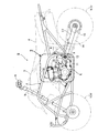
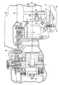
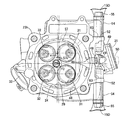
【解決手段】シリンダ23を起立状態にして車体フレームFに搭載され,シリンダ23の頭部23hには,ウォータジャケット46の水温を検出する水温センサ50を取り付けた車両用エンジンEであって,シリンダ23の頭部の一側に,吸気ポート31の上流端開口部40の直下に開口するセンサ取り付け孔47を設け,このセンサ取り付け孔47に水温センサ50を装着し,さらにシリンダ23の頭部23hには,水温センサ50を挟んで相対向する左右一対のハンガボス52,52を形成し,これらハンガボス52,52に,車体フレームFから延出するエンジンハンガブラケット15Dを固着する。
【選択図】 図3
Description
E・・・・・・・エンジン
F・・・・・・・車体フレーム
e・・・・・・・オフセット
15D・・・・・エンジンハンガブラケット(第4エンジンハンガブラケット)
23・・・・・・シリンダ
23h・・・・・シリンダの頭部(シリンダヘッド)
29・・・・・・燃焼室
31・・・・・・吸気ポート
32・・・・・・排気ポート
40・・・・・・吸気筒部
46・・・・・・ウォータジャケット
47・・・・・・センサ取り付け孔(第1センサ取り付け孔)
48・・・・・・取り付け座
79・・・・・・座ぐり
50・・・・・・水温センサ
50a・・・・・締めつけ部
52・・・・・・ハンガボス(第2ハンガボス)
57・・・・・・外接円
57a・・・・・上記外接円の中心
Claims (4)
- シリンダ(23)を起立状態にして車体フレーム(F)に搭載され,前記シリンダ(23)の頭部(23h)には,シリンダ(23)内の燃焼室(29)に開口する吸気ポート(31)及び排気ポート(32)が設けられると共に,シリンダ(23)内のウォータジャケット(46)の水温を検出する水温センサ(50)を取り付けた車両用エンジン(E)であって,
前記シリンダ(23)の頭部の一側に,前記吸気ポート(31)の上流端開口部(40)の直下に開口するセンサ取り付け孔(47)を設け,このセンサ取り付け孔(47)に前記水温センサ(50)を装着し,さらにシリンダ(23)の頭部(23h)には,前記水温センサ(50)を挟んで相対向する左右一対のハンガボス(52,52)を形成し,これらハンガボス(52,52)に,車体フレーム(F)から延出するエンジンハンガブラケット(15D)を固着することを特徴とする車両用エンジン。 - 請求項1記載の車両用エンジンンにおいて,
前記吸気ポート(31)の上流端開口部(40)として,シリンダ(23)の頭部の一側に,端面に前記吸気ポート(31)の上流端を開口させる吸気筒部(40)を突設し,この吸気筒部(40)の下部に,前記センサ取り付け孔(47)に装着される前記水温センサ(50)の締めつけ部(50a)が密着する取り付け座(48)を形成し,この取り付け座(48)の一部が前記吸気筒部(40)の下部に食い込むように,該吸気筒部(40)の下部に切欠き状の座ぐり(49)を削成したことを特徴とする,車両用エンジンン。 - 請求項1記載の車両用エンジンンにおいて,
前記吸気ポート(31)及び排気ポート(32)の前記燃焼室(29)への開口部を,これら開口部の周縁に対する外接円(57)の中心(57a)が前記シリンダ(23)の軸線(Y)より前記水温センサ(50)と反対側にオフセット(e)するように配置したことを特徴とする,車両用エンジンン。 - 請求項2記載の車両用エンジンンにおいて,
前記一対のハンガボス(52,52)を前記吸気筒部(40)を介して一体に連結したことを特徴とする,車両用エンジンン。
Priority Applications (2)
| Application Number | Priority Date | Filing Date | Title |
|---|---|---|---|
| JP2008225192A JP4890519B2 (ja) | 2008-09-02 | 2008-09-02 | 車両用エンジン |
| US12/508,120 US8499736B2 (en) | 2008-09-02 | 2009-07-23 | Engine for vehicle |
Applications Claiming Priority (1)
| Application Number | Priority Date | Filing Date | Title |
|---|---|---|---|
| JP2008225192A JP4890519B2 (ja) | 2008-09-02 | 2008-09-02 | 車両用エンジン |
Publications (2)
| Publication Number | Publication Date |
|---|---|
| JP2010059829A true JP2010059829A (ja) | 2010-03-18 |
| JP4890519B2 JP4890519B2 (ja) | 2012-03-07 |
Family
ID=41723477
Family Applications (1)
| Application Number | Title | Priority Date | Filing Date |
|---|---|---|---|
| JP2008225192A Active JP4890519B2 (ja) | 2008-09-02 | 2008-09-02 | 車両用エンジン |
Country Status (2)
| Country | Link |
|---|---|
| US (1) | US8499736B2 (ja) |
| JP (1) | JP4890519B2 (ja) |
Cited By (3)
| Publication number | Priority date | Publication date | Assignee | Title |
|---|---|---|---|---|
| JP2013177870A (ja) * | 2012-02-29 | 2013-09-09 | Honda Motor Co Ltd | 水冷式内燃機関の支持構造 |
| JP2014118879A (ja) * | 2012-12-17 | 2014-06-30 | Suzuki Motor Corp | エンジンの点火プラグ配置構造 |
| JP2017180328A (ja) * | 2016-03-30 | 2017-10-05 | 本田技研工業株式会社 | 鞍乗り型車両の内燃機関 |
Families Citing this family (1)
| Publication number | Priority date | Publication date | Assignee | Title |
|---|---|---|---|---|
| EP2837788B1 (en) * | 2012-03-16 | 2018-11-28 | Aichi Machine Industry Co., Ltd. | Internal combustion engine with a structure for retaining a temperature sensing device |
Family Cites Families (5)
| Publication number | Priority date | Publication date | Assignee | Title |
|---|---|---|---|---|
| JPH09126249A (ja) * | 1995-10-30 | 1997-05-13 | Fuji Heavy Ind Ltd | 電磁パウダクラッチの冷却機構 |
| US6296073B1 (en) * | 1999-06-23 | 2001-10-02 | Bombardier Inc. | All terrain vehicle with improved motor arrangement |
| JP4108954B2 (ja) | 2001-10-05 | 2008-06-25 | ヤマハ発動機株式会社 | 自動二輪車の燃料系配置構造 |
| JP2005280507A (ja) * | 2004-03-30 | 2005-10-13 | Yamaha Motor Co Ltd | 自動二輪車のエンジン支持装置 |
| JP4871223B2 (ja) * | 2006-09-14 | 2012-02-08 | 本田技研工業株式会社 | ラジエータを備える水冷式内燃機関 |
-
2008
- 2008-09-02 JP JP2008225192A patent/JP4890519B2/ja active Active
-
2009
- 2009-07-23 US US12/508,120 patent/US8499736B2/en active Active
Cited By (3)
| Publication number | Priority date | Publication date | Assignee | Title |
|---|---|---|---|---|
| JP2013177870A (ja) * | 2012-02-29 | 2013-09-09 | Honda Motor Co Ltd | 水冷式内燃機関の支持構造 |
| JP2014118879A (ja) * | 2012-12-17 | 2014-06-30 | Suzuki Motor Corp | エンジンの点火プラグ配置構造 |
| JP2017180328A (ja) * | 2016-03-30 | 2017-10-05 | 本田技研工業株式会社 | 鞍乗り型車両の内燃機関 |
Also Published As
| Publication number | Publication date |
|---|---|
| US20100050961A1 (en) | 2010-03-04 |
| US8499736B2 (en) | 2013-08-06 |
| JP4890519B2 (ja) | 2012-03-07 |
Similar Documents
| Publication | Publication Date | Title |
|---|---|---|
| JP5091062B2 (ja) | 車両用エンジン | |
| US10526982B2 (en) | Internal combustion engine with supercharger for saddle-ride type vehicle | |
| JP4964815B2 (ja) | V型内燃機関の吸気量制御装置 | |
| US7044253B2 (en) | Exhaust pipe structure of vehicle with low floor | |
| US9994286B2 (en) | Straddle type vehicle | |
| JP2010007645A (ja) | 自動二輪車の排気ガスセンサの取付け構造 | |
| JP2011149277A (ja) | 鞍乗型車両 | |
| JP6232960B2 (ja) | 自動二輪車の吸気ダクト装置 | |
| JP4890519B2 (ja) | 車両用エンジン | |
| JP2010014008A (ja) | オフロードビークル | |
| JP4717586B2 (ja) | 燃料噴射式エンジン、及びこれを備える自動二輪車 | |
| EP2332762B1 (en) | Servo motor layout structure of saddle-ride type vehicle | |
| WO2010113677A1 (ja) | 酸素濃度センサの取り付け構造 | |
| JP4287683B2 (ja) | 内燃機関 | |
| JPWO2018029822A1 (ja) | 鞍乗り型車両 | |
| JP2010228737A (ja) | 自動二輪車 | |
| JP2007127039A (ja) | 内燃機関 | |
| JP5227839B2 (ja) | 鞍乗り型車両の吸気装置構造 | |
| JP2011025763A (ja) | 自動二輪車 | |
| JP2010019200A (ja) | エンジンの燃料噴射装置 | |
| JP6062650B2 (ja) | 車両用スロットル装置 | |
| JP2012136996A (ja) | 内燃機関用クランク角検出装置 | |
| JP2010228739A (ja) | 自動二輪車 | |
| JP2018028323A (ja) | ユニットスイングエンジンにおけるノックセンサ取付け構造 | |
| JP2025103057A (ja) | 鞍乗型車両の排気装置 |
Legal Events
| Date | Code | Title | Description |
|---|---|---|---|
| A621 | Written request for application examination |
Free format text: JAPANESE INTERMEDIATE CODE: A621 Effective date: 20101126 |
|
| A977 | Report on retrieval |
Free format text: JAPANESE INTERMEDIATE CODE: A971007 Effective date: 20111109 |
|
| TRDD | Decision of grant or rejection written | ||
| A01 | Written decision to grant a patent or to grant a registration (utility model) |
Free format text: JAPANESE INTERMEDIATE CODE: A01 Effective date: 20111116 |
|
| A01 | Written decision to grant a patent or to grant a registration (utility model) |
Free format text: JAPANESE INTERMEDIATE CODE: A01 |
|
| A61 | First payment of annual fees (during grant procedure) |
Free format text: JAPANESE INTERMEDIATE CODE: A61 Effective date: 20111214 |
|
| R150 | Certificate of patent or registration of utility model |
Ref document number: 4890519 Country of ref document: JP Free format text: JAPANESE INTERMEDIATE CODE: R150 Free format text: JAPANESE INTERMEDIATE CODE: R150 |
|
| FPAY | Renewal fee payment (event date is renewal date of database) |
Free format text: PAYMENT UNTIL: 20141222 Year of fee payment: 3 |
|
| R250 | Receipt of annual fees |
Free format text: JAPANESE INTERMEDIATE CODE: R250 |