JP2010055737A - 光ピックアップ装置、焦点調整方法および光ディスク装置 - Google Patents
光ピックアップ装置、焦点調整方法および光ディスク装置 Download PDFInfo
- Publication number
- JP2010055737A JP2010055737A JP2009163888A JP2009163888A JP2010055737A JP 2010055737 A JP2010055737 A JP 2010055737A JP 2009163888 A JP2009163888 A JP 2009163888A JP 2009163888 A JP2009163888 A JP 2009163888A JP 2010055737 A JP2010055737 A JP 2010055737A
- Authority
- JP
- Japan
- Prior art keywords
- light
- signal
- spherical aberration
- optical
- laser
- Prior art date
- Legal status (The legal status is an assumption and is not a legal conclusion. Google has not performed a legal analysis and makes no representation as to the accuracy of the status listed.)
- Granted
Links
- 230000003287 optical effect Effects 0.000 title claims abstract description 124
- 238000000034 method Methods 0.000 title claims abstract description 27
- 230000004075 alteration Effects 0.000 claims abstract description 177
- 238000001514 detection method Methods 0.000 claims description 67
- 230000004907 flux Effects 0.000 claims description 44
- 201000009310 astigmatism Diseases 0.000 claims description 31
- 230000008859 change Effects 0.000 claims description 30
- 206010010071 Coma Diseases 0.000 claims description 20
- 238000004364 calculation method Methods 0.000 claims description 19
- 238000012937 correction Methods 0.000 claims description 18
- 206010073261 Ovarian theca cell tumour Diseases 0.000 claims description 11
- 208000001644 thecoma Diseases 0.000 claims description 11
- 238000012545 processing Methods 0.000 claims description 7
- 230000004044 response Effects 0.000 claims description 5
- 230000008569 process Effects 0.000 claims description 3
- 238000000926 separation method Methods 0.000 claims description 3
- 239000010410 layer Substances 0.000 description 72
- 238000004088 simulation Methods 0.000 description 21
- 230000009471 action Effects 0.000 description 15
- 238000010586 diagram Methods 0.000 description 15
- 230000010287 polarization Effects 0.000 description 10
- 230000000694 effects Effects 0.000 description 7
- 230000004048 modification Effects 0.000 description 7
- 238000012986 modification Methods 0.000 description 7
- 239000004065 semiconductor Substances 0.000 description 7
- 230000002093 peripheral effect Effects 0.000 description 5
- 230000006866 deterioration Effects 0.000 description 4
- 239000011229 interlayer Substances 0.000 description 3
- 230000001419 dependent effect Effects 0.000 description 2
- 238000013461 design Methods 0.000 description 2
- 238000006073 displacement reaction Methods 0.000 description 2
- 239000004973 liquid crystal related substance Substances 0.000 description 2
- 230000000630 rising effect Effects 0.000 description 2
- 230000003595 spectral effect Effects 0.000 description 2
- 230000002411 adverse Effects 0.000 description 1
- 230000015556 catabolic process Effects 0.000 description 1
- 238000006731 degradation reaction Methods 0.000 description 1
- 230000002542 deteriorative effect Effects 0.000 description 1
- 238000010030 laminating Methods 0.000 description 1
- 230000011218 segmentation Effects 0.000 description 1
Images


Classifications
-
- G—PHYSICS
- G11—INFORMATION STORAGE
- G11B—INFORMATION STORAGE BASED ON RELATIVE MOVEMENT BETWEEN RECORD CARRIER AND TRANSDUCER
- G11B7/00—Recording or reproducing by optical means, e.g. recording using a thermal beam of optical radiation by modifying optical properties or the physical structure, reproducing using an optical beam at lower power by sensing optical properties; Record carriers therefor
- G11B7/12—Heads, e.g. forming of the optical beam spot or modulation of the optical beam
- G11B7/135—Means for guiding the beam from the source to the record carrier or from the record carrier to the detector
- G11B7/1353—Diffractive elements, e.g. holograms or gratings
-
- G—PHYSICS
- G11—INFORMATION STORAGE
- G11B—INFORMATION STORAGE BASED ON RELATIVE MOVEMENT BETWEEN RECORD CARRIER AND TRANSDUCER
- G11B7/00—Recording or reproducing by optical means, e.g. recording using a thermal beam of optical radiation by modifying optical properties or the physical structure, reproducing using an optical beam at lower power by sensing optical properties; Record carriers therefor
- G11B7/08—Disposition or mounting of heads or light sources relatively to record carriers
- G11B7/085—Disposition or mounting of heads or light sources relatively to record carriers with provision for moving the light beam into, or out of, its operative position or across tracks, otherwise than during the transducing operation, e.g. for adjustment or preliminary positioning or track change or selection
- G11B7/08505—Methods for track change, selection or preliminary positioning by moving the head
- G11B7/08511—Methods for track change, selection or preliminary positioning by moving the head with focus pull-in only
-
- G—PHYSICS
- G11—INFORMATION STORAGE
- G11B—INFORMATION STORAGE BASED ON RELATIVE MOVEMENT BETWEEN RECORD CARRIER AND TRANSDUCER
- G11B7/00—Recording or reproducing by optical means, e.g. recording using a thermal beam of optical radiation by modifying optical properties or the physical structure, reproducing using an optical beam at lower power by sensing optical properties; Record carriers therefor
- G11B7/08—Disposition or mounting of heads or light sources relatively to record carriers
- G11B7/09—Disposition or mounting of heads or light sources relatively to record carriers with provision for moving the light beam or focus plane for the purpose of maintaining alignment of the light beam relative to the record carrier during transducing operation, e.g. to compensate for surface irregularities of the latter or for track following
- G11B7/0908—Disposition or mounting of heads or light sources relatively to record carriers with provision for moving the light beam or focus plane for the purpose of maintaining alignment of the light beam relative to the record carrier during transducing operation, e.g. to compensate for surface irregularities of the latter or for track following for focusing only
- G11B7/0909—Disposition or mounting of heads or light sources relatively to record carriers with provision for moving the light beam or focus plane for the purpose of maintaining alignment of the light beam relative to the record carrier during transducing operation, e.g. to compensate for surface irregularities of the latter or for track following for focusing only by astigmatic methods
-
- G—PHYSICS
- G11—INFORMATION STORAGE
- G11B—INFORMATION STORAGE BASED ON RELATIVE MOVEMENT BETWEEN RECORD CARRIER AND TRANSDUCER
- G11B7/00—Recording or reproducing by optical means, e.g. recording using a thermal beam of optical radiation by modifying optical properties or the physical structure, reproducing using an optical beam at lower power by sensing optical properties; Record carriers therefor
- G11B7/08—Disposition or mounting of heads or light sources relatively to record carriers
- G11B7/09—Disposition or mounting of heads or light sources relatively to record carriers with provision for moving the light beam or focus plane for the purpose of maintaining alignment of the light beam relative to the record carrier during transducing operation, e.g. to compensate for surface irregularities of the latter or for track following
- G11B7/0908—Disposition or mounting of heads or light sources relatively to record carriers with provision for moving the light beam or focus plane for the purpose of maintaining alignment of the light beam relative to the record carrier during transducing operation, e.g. to compensate for surface irregularities of the latter or for track following for focusing only
- G11B7/0912—Disposition or mounting of heads or light sources relatively to record carriers with provision for moving the light beam or focus plane for the purpose of maintaining alignment of the light beam relative to the record carrier during transducing operation, e.g. to compensate for surface irregularities of the latter or for track following for focusing only by push-pull method
-
- G—PHYSICS
- G11—INFORMATION STORAGE
- G11B—INFORMATION STORAGE BASED ON RELATIVE MOVEMENT BETWEEN RECORD CARRIER AND TRANSDUCER
- G11B7/00—Recording or reproducing by optical means, e.g. recording using a thermal beam of optical radiation by modifying optical properties or the physical structure, reproducing using an optical beam at lower power by sensing optical properties; Record carriers therefor
- G11B7/08—Disposition or mounting of heads or light sources relatively to record carriers
- G11B7/09—Disposition or mounting of heads or light sources relatively to record carriers with provision for moving the light beam or focus plane for the purpose of maintaining alignment of the light beam relative to the record carrier during transducing operation, e.g. to compensate for surface irregularities of the latter or for track following
- G11B7/0943—Methods and circuits for performing mathematical operations on individual detector segment outputs
-
- G—PHYSICS
- G11—INFORMATION STORAGE
- G11B—INFORMATION STORAGE BASED ON RELATIVE MOVEMENT BETWEEN RECORD CARRIER AND TRANSDUCER
- G11B7/00—Recording or reproducing by optical means, e.g. recording using a thermal beam of optical radiation by modifying optical properties or the physical structure, reproducing using an optical beam at lower power by sensing optical properties; Record carriers therefor
- G11B7/08—Disposition or mounting of heads or light sources relatively to record carriers
- G11B7/09—Disposition or mounting of heads or light sources relatively to record carriers with provision for moving the light beam or focus plane for the purpose of maintaining alignment of the light beam relative to the record carrier during transducing operation, e.g. to compensate for surface irregularities of the latter or for track following
- G11B7/095—Disposition or mounting of heads or light sources relatively to record carriers with provision for moving the light beam or focus plane for the purpose of maintaining alignment of the light beam relative to the record carrier during transducing operation, e.g. to compensate for surface irregularities of the latter or for track following specially adapted for discs, e.g. for compensation of eccentricity or wobble
- G11B7/0956—Disposition or mounting of heads or light sources relatively to record carriers with provision for moving the light beam or focus plane for the purpose of maintaining alignment of the light beam relative to the record carrier during transducing operation, e.g. to compensate for surface irregularities of the latter or for track following specially adapted for discs, e.g. for compensation of eccentricity or wobble to compensate for tilt, skew, warp or inclination of the disc, i.e. maintain the optical axis at right angles to the disc
-
- G—PHYSICS
- G11—INFORMATION STORAGE
- G11B—INFORMATION STORAGE BASED ON RELATIVE MOVEMENT BETWEEN RECORD CARRIER AND TRANSDUCER
- G11B7/00—Recording or reproducing by optical means, e.g. recording using a thermal beam of optical radiation by modifying optical properties or the physical structure, reproducing using an optical beam at lower power by sensing optical properties; Record carriers therefor
- G11B7/12—Heads, e.g. forming of the optical beam spot or modulation of the optical beam
- G11B7/13—Optical detectors therefor
- G11B7/131—Arrangement of detectors in a multiple array
-
- G—PHYSICS
- G11—INFORMATION STORAGE
- G11B—INFORMATION STORAGE BASED ON RELATIVE MOVEMENT BETWEEN RECORD CARRIER AND TRANSDUCER
- G11B7/00—Recording or reproducing by optical means, e.g. recording using a thermal beam of optical radiation by modifying optical properties or the physical structure, reproducing using an optical beam at lower power by sensing optical properties; Record carriers therefor
- G11B7/12—Heads, e.g. forming of the optical beam spot or modulation of the optical beam
- G11B7/13—Optical detectors therefor
- G11B7/133—Shape of individual detector elements
-
- G—PHYSICS
- G11—INFORMATION STORAGE
- G11B—INFORMATION STORAGE BASED ON RELATIVE MOVEMENT BETWEEN RECORD CARRIER AND TRANSDUCER
- G11B7/00—Recording or reproducing by optical means, e.g. recording using a thermal beam of optical radiation by modifying optical properties or the physical structure, reproducing using an optical beam at lower power by sensing optical properties; Record carriers therefor
- G11B7/12—Heads, e.g. forming of the optical beam spot or modulation of the optical beam
- G11B7/135—Means for guiding the beam from the source to the record carrier or from the record carrier to the detector
- G11B7/1381—Non-lens elements for altering the properties of the beam, e.g. knife edges, slits, filters or stops
-
- G—PHYSICS
- G11—INFORMATION STORAGE
- G11B—INFORMATION STORAGE BASED ON RELATIVE MOVEMENT BETWEEN RECORD CARRIER AND TRANSDUCER
- G11B7/00—Recording or reproducing by optical means, e.g. recording using a thermal beam of optical radiation by modifying optical properties or the physical structure, reproducing using an optical beam at lower power by sensing optical properties; Record carriers therefor
- G11B7/12—Heads, e.g. forming of the optical beam spot or modulation of the optical beam
- G11B7/135—Means for guiding the beam from the source to the record carrier or from the record carrier to the detector
- G11B7/1392—Means for controlling the beam wavefront, e.g. for correction of aberration
- G11B7/13925—Means for controlling the beam wavefront, e.g. for correction of aberration active, e.g. controlled by electrical or mechanical means
- G11B7/13927—Means for controlling the beam wavefront, e.g. for correction of aberration active, e.g. controlled by electrical or mechanical means during transducing, e.g. to correct for variation of the spherical aberration due to disc tilt or irregularities in the cover layer thickness
-
- G—PHYSICS
- G11—INFORMATION STORAGE
- G11B—INFORMATION STORAGE BASED ON RELATIVE MOVEMENT BETWEEN RECORD CARRIER AND TRANSDUCER
- G11B7/00—Recording or reproducing by optical means, e.g. recording using a thermal beam of optical radiation by modifying optical properties or the physical structure, reproducing using an optical beam at lower power by sensing optical properties; Record carriers therefor
- G11B2007/0003—Recording, reproducing or erasing systems characterised by the structure or type of the carrier
- G11B2007/0009—Recording, reproducing or erasing systems characterised by the structure or type of the carrier for carriers having data stored in three dimensions, e.g. volume storage
- G11B2007/0013—Recording, reproducing or erasing systems characterised by the structure or type of the carrier for carriers having data stored in three dimensions, e.g. volume storage for carriers having multiple discrete layers
Landscapes
- Physics & Mathematics (AREA)
- Optics & Photonics (AREA)
- Mathematical Physics (AREA)
- Optical Head (AREA)
- Optical Recording Or Reproduction (AREA)
Abstract
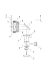
【解決手段】ディスクによって反射されたレーザ光のうち、レーザ光軸の周りに設定された4つの光束領域A〜Dの光束の進行方向を変化させ、光束領域A〜Dの光束を互いに離散させる。光検出器の検出面には、信号光のみが存在する信号光領域が現れる。この領域にセンサパターンを配置する。また、この領域の内側に、球面収差検出用のセンサパターンを配置する。これにより、迷光の影響を除去でき、且つ、球面収差の検出が可能となる。
【選択図】図11
Description
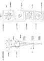
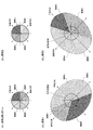
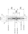
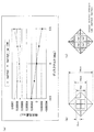
まず、図1ないし図10を参照して、本実施の形態に適用される技術的原理について説明する。
(1)往路倍率:10倍
(2)復路倍率:18倍
(3)角度調整素子16によって付与される分光角度:1.9度
(4)角度調整素子16の分光面と光検出器17の検出面の間の光路長:3mm
(5)角度調整素子16を配さないときの光検出面上におけるスポット径:60μm
(6)角度調整素子16を配したときの光検出面上における各信号光(光束領域A〜Dをそれぞれ通過)の変位距離:100μm
以下、上記原理に基づく実施例について説明する。
光ディスク装置は、より詳細には、以下のように構成され得る。なお、以下には、複数の記録層を有する光ディスクに対して再生を行う光ディスク装置を例示する。
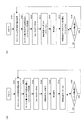
図26(d)のフローチャートでは、再生位置がディスク半径方向に所定量だけ変化する毎に球面収差サーボを行うようにしたが、本変更例では、再生時に常時、球面収差サーボが行われる。
104 レンズアクチュエータ(球面収差補正ユニット)
107 対物レンズ
109 対物レンズアクチュエータ(コマ収差補正ユニット)
110 検出レンズ(非点収差素子)
111 角度調整素子
112 光検出器
P11〜P18 センサ(第1のセンサ部)
Sa1〜Sa4 センサ(第2のセンサ部)
121、122 光検出器
130 角度調整素子
201 信号演算回路(第1の演算回路、第2の演算回路、演算回路)
203 サーボ回路(回路部)
325 ローパスフィルタ
Claims (18)
- レーザ光源と、
前記レーザ光源から出射されたレーザ光を記録媒体上に収束させる対物レンズと、
前記記録媒体によって反射された前記レーザ光に非点収差を導入し、これにより、第1の方向に前記レーザ光が収束することによって生じる第1の焦線位置と、前記第1の方向に垂直な第2の方向に前記レーザ光が収束することによって生じる第2の焦線位置とを前記レーザ光の進行方向に互いに離間させる非点収差素子と、
前記記録媒体によって反射された前記レーザ光のうち、異なる4つの光束領域内の光束の進行方向を互いに異ならせ、これら4つの光束領域内の光束を互いに離散させる角度調整素子と、
前記離散された各光束を受光して検出信号を出力する光検出器と、
前記レーザ光に生じる球面収差を補正する球面収差補正ユニットと、
を備え、
前記角度調整素子は、前記第1の方向と前記第2の方向にそれぞれ平行で且つ互いにクロスする2つの直線の交点を前記レーザ光軸に整合させたとき、前記2つの直線によって作られる一組の対頂角が並ぶ方向に2つの前記光束領域が配置され、他の一組の対頂角が並ぶ方向に残りの2つの前記光束領域が配置されるよう、前記4つの光束領域を設定し、
前記光検出器は、前記4つの光束をそれぞれ受光する位置に配された第1のセンサ部と、球面収差による前記光束の強度分布の変化を検出する第2のセンサ部とを有する、
ことを特徴とする光ピックアップ装置。 - 請求項1に記載の光ピックアップ装置において、
前記4つの光束領域は、前記2つの直線によって前記レーザ光の光束領域を分割することにより設定されている、
ことを特徴とする光ピックアップ装置。 - 請求項1または2に記載の光ピックアップ装置において、
前記角度調整素子は、離散後の各光束が前記光検出器の受光面上において正方形の異なる4つの頂角の位置にそれぞれ導かれるよう、4つの前記光束領域の進行方向を、前記第1および第2の方向に対し45°の方向で、且つ、所定の角度だけ変化させる、
ことを特徴とする光ピックアップ装置。 - 請求項3に記載の光ピックアップ装置において、
前記第2のセンサ部は、前記正方形の互いに対向する2つの辺の並び方向に配された2つのセンサと、残り2つの辺の並び方向に配された2つのセンサとを有する、
ことを特徴とする光ピックアップ装置。 - 請求項4に記載の光ピックアップ装置において、
前記正方形の互いに対向する2つの辺の並び方向に配された2つの前記センサにおける総受光量に対応する検出信号と、残り2つの辺の並び方向に配された2つの前記センサにおける総受光量に対応する検出信号の差分を演算する第1の演算回路を備える、
ことを特徴とする光ピックアップ装置。 - 請求項4または5に記載の光ピックアップ装置において、
前記第2のセンサ部を構成する4つの前記センサの各受光領域は、前記第1のセンサ部に囲まれた領域を、前記正方形の互いに対向する2つの頂点を結ぶ直線と残り2つの頂点を結ぶ直線によって4分割した領域となっている、
ことを特徴とする光ピックアップ装置。 - 請求項6に記載の光ピックアップ装置において、
前記正方形の互いに対向する2つの頂点を結ぶ一つの直線によって4つの前記センサを2つのグループに区分したとき、一方のセンサグループにおける総受光量に対応する検出信号と、他方のセンサグループにおける総受光量に対応する検出信号の差分を演算する第2の演算回路を備える、
ことを特徴とする光ピックアップ装置。 - 照射光の焦点位置を目標面上に位置づける焦点調整方法であって、
前記目標面によって反射された前記照射光に非点収差を導入し、これにより、第1の方向に前記照射光が収束することによって生じる第1の焦線位置と、前記第1の方向に垂直な第2の方向に前記照射光が収束することによって生じる第2の焦線位置とを前記照射光の進行方向に互いに離間させ、
前記目標面によって反射された前記照射光のうち、異なる4つの光束領域内の光束の進行方向を互いに異ならせて、これら4つの光束領域内の光束を互いに離散させ、
前記離散された各光束を光検出器にて受光し、
前記4つの光束領域は、前記第1の方向と前記第2の方向にそれぞれ平行で且つ互いにクロスする2つの直線の交点を前記照射光の光軸に整合させたとき、前記2つの直線によって作られる一組の対頂角が並ぶ方向に2つの前記光束領域が配置され、他の一組の対頂角が並ぶ方向に残りの2つの前記光束領域が配置されるように設定されており、
前記光検出器は、前記4つの光束をそれぞれ受光する位置に配された第1のセンサ部と、球面収差による前記光束の強度分布の変化を検出する第2のセンサ部とを有し、
前記第1のセンサ部から出力された検出信号に対し非点収差法に基づく演算処理を行ってフォーカスエラー信号を生成し、
前記第2のセンサ部から出力された検出信号に基づいて球面収差を表す信号を生成する、
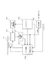
ことを特徴とする焦点調整方法。 - 請求項1に記載の光ピックアップ装置と、
前記光検出器からの信号を演算処理する演算回路と、
前記演算回路からの信号に基づいて前記対物レンズおよび前記球面収差補正ユニットを駆動制御するサーボ回路と、
を備えることを特徴する光ディスク装置。 - 請求項9に記載の光ディスク装置において、
前記角度調整素子は、離散後の各光束が前記光検出器の受光面上において正方形の異なる4つの頂角の位置にそれぞれ導かれるよう、4つの前記光束領域の進行方向を、前記第1および第2の方向に対し45°の方向で、且つ、所定の角度だけ変化させる、
ことを特徴とする光ディスク装置。 - 請求項10に記載の光ディスク装置において、
前記第2のセンサ部は、前記正方形の互いに対向する2つの辺の並び方向に配された2つのセンサと、残り2つの辺の並び方向に配された2つのセンサとを有する、
ことを特徴とする光ディスク装置。 - 請求項11に記載の光ディスク装置において、
前記演算回路は、前記正方形の互いに対向する2つの辺の並び方向に配された2つの前記センサにおける総受光量に対応する検出信号と、残り2つの辺の並び方向に配された2つの前記センサにおける総受光量に対応する検出信号の差分を演算する第1の演算回路を備え、
前記サーボ回路は、前記第1の演算回路による演算結果に基づいて、前記球面収差補正ユニットを制御する、
ことを特徴とする光ディスク装置。 - 請求項11または12に記載の光ディスク装置において、
前記第2のセンサ部を構成する4つの前記センサの各受光領域は、前記第1のセンサ部に囲まれた領域を、前記正方形の互いに対向する2つの頂点を結ぶ直線と残り2つの頂点を結ぶ直線によって4分割した領域となっている、
ことを特徴とする光ディスク装置。 - 請求項13に記載の光ディスク装置において、
前記レーザ光に生じるコマ収差を補正するコマ収差補正ユニットをさらに備え、
前記演算回路は、前記正方形の互いに対向する2つの頂点を結ぶ一つの直線によって4つの前記センサを2つのグループに区分したとき、一方のセンサグループにおける総受光量に対応する検出信号と、他方のセンサグループにおける総受光量に対応する検出信号の差分を演算する第2の演算回路を備え、
前記サーボ回路は、前記第2の演算回路による演算結果に基づいて、前記コマ収差補正ユニットを駆動制御する、
ことを特徴とする光ディスク装置。 - 請求項9ないし14の何れか一項に記載の光ディスク装置において、
前記サーボ回路は、光ディスクに対する再生または記録に並行して、前記球面収差補正ユニットを駆動制御する、
ことを特徴とする光ディスク装置。 - 請求項9ないし14の何れか一項に記載の光ディスク装置において、
前記サーボ回路は、光ディスクに対する前記レーザ光の照射位置が前記光ディスクの径方向に所定量変化する毎に、前記球面収差補正ユニットを駆動制御する、
ことを特徴とする光ディスク装置。 - 請求項9ないし14の何れか一項に記載の光ディスク装置において、
前記演算回路は、前記第2のセンサ部からの出力信号に基づいて前記球面収差に応じた収差信号を生成し、
前記光ディスク装置は、前記収差信号が入力されるローパスフィルタをさらに備え、
前記サーボ回路は、前記ローパスフィルタからの出力に基づいて前記球面収差補正ユニットを制御する、
ことを特徴とする光ディスク装置。 - 請求項17に記載の光ディスク装置において、
前記光ディスクは、積層方向に複数の記録層を有し、
前記光ディスク装置は、前記ローパスフィルタの時定数を変化させるための回路部をさらに備え、
前記レーザ光の照射対象が第1の記録層から第2の記録層に切り替えられるとき、前記サーボ回路の応答速度が高められる、
ことを特徴とする光ディスク装置。
Priority Applications (1)
| Application Number | Priority Date | Filing Date | Title |
|---|---|---|---|
| JP2009163888A JP5173953B2 (ja) | 2008-08-01 | 2009-07-10 | 光ピックアップ装置および光ディスク装置 |
Applications Claiming Priority (3)
| Application Number | Priority Date | Filing Date | Title |
|---|---|---|---|
| JP2008200264 | 2008-08-01 | ||
| JP2008200264 | 2008-08-01 | ||
| JP2009163888A JP5173953B2 (ja) | 2008-08-01 | 2009-07-10 | 光ピックアップ装置および光ディスク装置 |
Publications (2)
| Publication Number | Publication Date |
|---|---|
| JP2010055737A true JP2010055737A (ja) | 2010-03-11 |
| JP5173953B2 JP5173953B2 (ja) | 2013-04-03 |
Family
ID=41608243
Family Applications (1)
| Application Number | Title | Priority Date | Filing Date |
|---|---|---|---|
| JP2009163888A Expired - Fee Related JP5173953B2 (ja) | 2008-08-01 | 2009-07-10 | 光ピックアップ装置および光ディスク装置 |
Country Status (2)
| Country | Link |
|---|---|
| US (1) | US7990835B2 (ja) |
| JP (1) | JP5173953B2 (ja) |
Cited By (1)
| Publication number | Priority date | Publication date | Assignee | Title |
|---|---|---|---|---|
| WO2012114583A1 (ja) * | 2011-02-24 | 2012-08-30 | 三洋電機株式会社 | 光ピックアップ装置 |
Families Citing this family (8)
| Publication number | Priority date | Publication date | Assignee | Title |
|---|---|---|---|---|
| JP4610628B2 (ja) * | 2008-03-04 | 2011-01-12 | 三洋電機株式会社 | 光ピックアップ装置および焦点調整方法 |
| JP4610662B2 (ja) * | 2008-09-29 | 2011-01-12 | 三洋電機株式会社 | 光ピックアップ装置および光ディスク装置 |
| JP2012033230A (ja) * | 2010-07-30 | 2012-02-16 | Sanyo Electric Co Ltd | 光ピックアップ装置 |
| JP2012033231A (ja) * | 2010-07-30 | 2012-02-16 | Sanyo Electric Co Ltd | 光ピックアップ装置 |
| JP5571189B2 (ja) * | 2010-11-24 | 2014-08-13 | 株式会社東芝 | 光ピックアップおよび光ディスク装置 |
| JP2013012277A (ja) * | 2011-06-29 | 2013-01-17 | Sanyo Electric Co Ltd | 光ピックアップ装置 |
| JP2013033582A (ja) * | 2011-06-29 | 2013-02-14 | Sanyo Electric Co Ltd | 光ピックアップ装置および分光素子の位置調整方法 |
| US8755260B2 (en) * | 2011-07-18 | 2014-06-17 | Marvell World Trade Ltd. | Collimator for optical pick-up units |
Citations (4)
| Publication number | Priority date | Publication date | Assignee | Title |
|---|---|---|---|---|
| JP2005044466A (ja) * | 2003-07-25 | 2005-02-17 | Victor Co Of Japan Ltd | 球面収差補正装置 |
| JP2007257803A (ja) * | 2006-03-24 | 2007-10-04 | Sharp Corp | 光ピックアップの制御装置および制御方法、光ディスク装置、光ピックアップ制御プログラム、並びに該プログラムを記録した記録媒体 |
| JP2007335047A (ja) * | 2006-06-19 | 2007-12-27 | Sony Corp | 光ディスク装置、およびピックアップ装置 |
| JP2008171470A (ja) * | 2007-01-09 | 2008-07-24 | Victor Co Of Japan Ltd | 光ピックアップ装置 |
Family Cites Families (8)
| Publication number | Priority date | Publication date | Assignee | Title |
|---|---|---|---|---|
| NL8105579A (nl) * | 1981-12-11 | 1983-07-01 | Philips Nv | Optisch fokusfoutdetektiestelsel. |
| JP3658763B2 (ja) * | 1992-02-07 | 2005-06-08 | ソニー株式会社 | 光磁気記憶装置用光ピックアップ装置 |
| US6967908B2 (en) * | 2000-09-07 | 2005-11-22 | Pioneer Corporation | Optical pickup device with focus error detecting optical element and method for focus error detection |
| JP2002109778A (ja) * | 2000-09-29 | 2002-04-12 | Pioneer Electronic Corp | 光ピックアップ装置 |
| CN100341057C (zh) * | 2002-10-10 | 2007-10-03 | 松下电器产业株式会社 | 光学头及光盘装置 |
| JP4859089B2 (ja) | 2005-03-14 | 2012-01-18 | 株式会社リコー | 抽出光学系、光ピックアップ装置及び光ディスク装置 |
| JP2006260669A (ja) | 2005-03-16 | 2006-09-28 | Ricoh Co Ltd | 光情報記録再生装置及び記録媒体 |
| US20080165655A1 (en) * | 2007-01-09 | 2008-07-10 | Ryo Saitoh | Optical pickup device |
-
2009
- 2009-07-10 JP JP2009163888A patent/JP5173953B2/ja not_active Expired - Fee Related
- 2009-07-30 US US12/512,440 patent/US7990835B2/en not_active Expired - Fee Related
Patent Citations (4)
| Publication number | Priority date | Publication date | Assignee | Title |
|---|---|---|---|---|
| JP2005044466A (ja) * | 2003-07-25 | 2005-02-17 | Victor Co Of Japan Ltd | 球面収差補正装置 |
| JP2007257803A (ja) * | 2006-03-24 | 2007-10-04 | Sharp Corp | 光ピックアップの制御装置および制御方法、光ディスク装置、光ピックアップ制御プログラム、並びに該プログラムを記録した記録媒体 |
| JP2007335047A (ja) * | 2006-06-19 | 2007-12-27 | Sony Corp | 光ディスク装置、およびピックアップ装置 |
| JP2008171470A (ja) * | 2007-01-09 | 2008-07-24 | Victor Co Of Japan Ltd | 光ピックアップ装置 |
Cited By (1)
| Publication number | Priority date | Publication date | Assignee | Title |
|---|---|---|---|---|
| WO2012114583A1 (ja) * | 2011-02-24 | 2012-08-30 | 三洋電機株式会社 | 光ピックアップ装置 |
Also Published As
| Publication number | Publication date |
|---|---|
| JP5173953B2 (ja) | 2013-04-03 |
| US20100027405A1 (en) | 2010-02-04 |
| US7990835B2 (en) | 2011-08-02 |
Similar Documents
| Publication | Publication Date | Title |
|---|---|---|
| JP5173953B2 (ja) | 光ピックアップ装置および光ディスク装置 | |
| US7558162B2 (en) | Optical pick-up head, optical information apparatus, and optical information reproducing method | |
| JP4610662B2 (ja) | 光ピックアップ装置および光ディスク装置 | |
| JP4610628B2 (ja) | 光ピックアップ装置および焦点調整方法 | |
| US20070237040A1 (en) | Optical head and optical disk device | |
| JP5173659B2 (ja) | 光ピックアップ装置および光ディスク装置 | |
| JP5173656B2 (ja) | 光ピックアップ装置 | |
| JPH11259893A (ja) | 光学ヘッド、記録及び/又は再生装置並びに記録及び/又は再生方法、並びに厚み検出方法 | |
| JP2002092932A (ja) | 光ヘッド、受発光素子、及び光記録媒体記録再生装置 | |
| JP4684341B2 (ja) | 光ピックアップ装置、光ディスク装置および焦点調整方法 | |
| JP2011070752A (ja) | 光ピックアップ装置 | |
| JP2011008852A (ja) | 光ピックアップ装置 | |
| JP4722190B2 (ja) | 光ピックアップ装置および光ディスク装置 | |
| JP5227930B2 (ja) | 光ピックアップ装置 | |
| JP4722205B2 (ja) | 光ピックアップ装置および光ディスク装置 | |
| JP5173868B2 (ja) | 光ピックアップ装置および光ディスク装置 | |
| JP3685797B2 (ja) | 光ディスク装置 | |
| JP2006309858A (ja) | 光ディスク装置 | |
| JP2010079983A (ja) | 光ピックアップ装置および光ディスク装置 | |
| JP2010049758A (ja) | 光ピックアップ装置 | |
| JP2006513515A (ja) | 光記録媒体からの読出し及び/又は光記録媒体への書込みのための装置 | |
| JP2005174503A (ja) | 光ピックアップおよび光ディスク装置 | |
| JP2008047198A (ja) | 光ピックアップ装置 | |
| JP2008047199A (ja) | 光ピックアップ装置 | |
| JP2010080005A (ja) | 光ピックアップ装置および光ディスク装置 |
Legal Events
| Date | Code | Title | Description |
|---|---|---|---|
| A621 | Written request for application examination |
Free format text: JAPANESE INTERMEDIATE CODE: A621 Effective date: 20120622 |
|
| A977 | Report on retrieval |
Free format text: JAPANESE INTERMEDIATE CODE: A971007 Effective date: 20121108 |
|
| A131 | Notification of reasons for refusal |
Free format text: JAPANESE INTERMEDIATE CODE: A131 Effective date: 20121113 |
|
| A521 | Written amendment |
Free format text: JAPANESE INTERMEDIATE CODE: A523 Effective date: 20121116 |
|
| TRDD | Decision of grant or rejection written | ||
| A01 | Written decision to grant a patent or to grant a registration (utility model) |
Free format text: JAPANESE INTERMEDIATE CODE: A01 Effective date: 20121204 |
|
| A61 | First payment of annual fees (during grant procedure) |
Free format text: JAPANESE INTERMEDIATE CODE: A61 Effective date: 20121227 |
|
| FPAY | Renewal fee payment (event date is renewal date of database) |
Free format text: PAYMENT UNTIL: 20160111 Year of fee payment: 3 |
|
| LAPS | Cancellation because of no payment of annual fees |